EP4047778A1 - Cc-cp-cv charging of lithium-based batteries - Google Patents
Cc-cp-cv charging of lithium-based batteries Download PDFInfo
- Publication number
- EP4047778A1 EP4047778A1 EP21158602.9A EP21158602A EP4047778A1 EP 4047778 A1 EP4047778 A1 EP 4047778A1 EP 21158602 A EP21158602 A EP 21158602A EP 4047778 A1 EP4047778 A1 EP 4047778A1
- Authority
- EP
- European Patent Office
- Prior art keywords
- cell
- voltage
- charging current
- battery
- charging
- Prior art date
- Legal status (The legal status is an assumption and is not a legal conclusion. Google has not performed a legal analysis and makes no representation as to the accuracy of the status listed.)
- Pending
Links
Images


Classifications
-
- H—ELECTRICITY
- H02—GENERATION; CONVERSION OR DISTRIBUTION OF ELECTRIC POWER
- H02J—ELECTRIC POWER NETWORKS; CIRCUIT ARRANGEMENTS OR SYSTEMS FOR SUPPLYING OR DISTRIBUTING ELECTRIC POWER; SYSTEMS FOR STORING ELECTRIC ENERGY
- H02J7/00—Circuit arrangements for charging or discharging batteries or for supplying loads from batteries
- H02J7/90—Regulation of charging or discharging current or voltage
- H02J7/933—Regulation of charging or discharging current or voltage the cycle being controlled or terminated in response to electric parameters
-
- H—ELECTRICITY
- H01—ELECTRIC ELEMENTS
- H01M—PROCESSES OR MEANS, e.g. BATTERIES, FOR THE DIRECT CONVERSION OF CHEMICAL ENERGY INTO ELECTRICAL ENERGY
- H01M10/00—Secondary cells; Manufacture thereof
- H01M10/42—Methods or arrangements for servicing or maintenance of secondary cells or secondary half-cells
- H01M10/44—Methods for charging or discharging
-
- H—ELECTRICITY
- H01—ELECTRIC ELEMENTS
- H01M—PROCESSES OR MEANS, e.g. BATTERIES, FOR THE DIRECT CONVERSION OF CHEMICAL ENERGY INTO ELECTRICAL ENERGY
- H01M10/00—Secondary cells; Manufacture thereof
- H01M10/42—Methods or arrangements for servicing or maintenance of secondary cells or secondary half-cells
- H01M10/48—Accumulators combined with arrangements for measuring, testing or indicating the condition of cells, e.g. the level or density of the electrolyte
-
- H—ELECTRICITY
- H02—GENERATION; CONVERSION OR DISTRIBUTION OF ELECTRIC POWER
- H02J—ELECTRIC POWER NETWORKS; CIRCUIT ARRANGEMENTS OR SYSTEMS FOR SUPPLYING OR DISTRIBUTING ELECTRIC POWER; SYSTEMS FOR STORING ELECTRIC ENERGY
- H02J7/00—Circuit arrangements for charging or discharging batteries or for supplying loads from batteries
- H02J7/90—Regulation of charging or discharging current or voltage
- H02J7/96—Regulation of charging or discharging current or voltage in response to battery voltage
-
- H—ELECTRICITY
- H01—ELECTRIC ELEMENTS
- H01M—PROCESSES OR MEANS, e.g. BATTERIES, FOR THE DIRECT CONVERSION OF CHEMICAL ENERGY INTO ELECTRICAL ENERGY
- H01M10/00—Secondary cells; Manufacture thereof
- H01M10/05—Accumulators with non-aqueous electrolyte
- H01M10/052—Li-accumulators
- H01M10/0525—Rocking-chair batteries, i.e. batteries with lithium insertion or intercalation in both electrodes; Lithium-ion batteries
Definitions
- the present invention relates to charging of Lithium-based batteries, and in particular to a method of operating a battery charger for a Lithium-based battery, a corresponding battery charger, and an emergency power supply for an LED lighting system comprising a Lithium-based battery and a battery charger.
- rechargeable Lithium-based batteries have grown in popularity owing to high energy density, low self-discharge and absent memory effect.
- Charging of Lithium-based batteries typically involves constant current - constant voltage (CC-CV) algorithms.
- CC-CV constant current - constant voltage
- the electronic components are thus subject to high power ratings and high peak temperatures that shorten their lifetime.
- the object of the present invention is to loosen a worst-case power condition of a battery charger for Lithium-based batteries.
- a method of operating a battery charger is provided.
- the method is for a Lithium-based battery comprising a cell and comprises: connecting the battery to a powered battery charger; responsive to a voltage of the cell being below a threshold voltage , applying a constant charging current to the cell until a charging power is equal to or above a target power; applying a charging current lower than the constant charging current to the cell until the voltage of the cell is equal to or above a maximum charging voltage; and applying the maximum charging voltage to the cell until the charging current is equal to or below a threshold current.
- the applying of the charging current lower than the constant charging current to the cell may comprise: applying a charging current decreasing in dependence of the voltage of the cell.
- the applying of the charging current lower than the constant charging current to the cell may comprise: applying the target power to the cell.
- the method may further comprise responsive to the voltage of the cell being equal to or below a further threshold voltage, triggering the applying of the charging current lower than the constant charging current to the cell.
- the further threshold voltage may comprise 15/18, preferably 16/18, and most preferably 17/18 of the maximum charging voltage.
- the constant charging current may depend on at least one of a minimum rated capacity of the battery, and a production tolerance of the minimum rated capacity.
- the constant charging current may exceed a constant charging current of known CC-CV LFP battery chargers.
- the threshold current may comprise 3/9, preferably 2/9, and most preferably 1/9 of the constant charging current.
- the threshold voltage may comprise 24/27, preferably 22/27, and most preferably 20/27 of a maximum charging voltage of the maximum charging voltage.
- the battery may comprise a number of stages in series each having a number of cells in parallel.
- the target power may depend on the number of stages.
- the charging current may be equal to or below the threshold current within a maximum recharge time defined by relevant standards, e.g. 24 hours.
- the Lithium-based battery may comprise a Lithium ion cell or a Lithium ferro-phosphate cell.
- a battery charger for a Lithium-based battery comprising a cell.
- the battery charger comprises: input terminals connectable to a source of electrical power; output terminals connectable to the battery; a power converter interconnecting the input terminals and the output terminals; and a controller unit.
- the controller unit is configured to measure a voltage of the cell, a charging current and a charging power of the battery.
- the controller unit is configured to, responsive to the voltage of the cell being below a threshold voltage , apply a constant charging current to the cell until the charging power is equal to or above a target power.
- the controller unit is configured to apply a charging current lower than the constant charging current to the cell until the voltage of the cell is equal to or above a maximum charging voltage.
- the controller unit is configured to apply the maximum charging voltage to the cell until the charging current is equal to or below a threshold current.
- controller unit may further be configured to carry out the method of the first aspect or any of its embodiments of operating the battery charger.
- an emergency power supply for an LED lighting system comprises: a Lithium-based battery comprising a cell; and a battery charger of the second aspect or any of its embodiments.
- the present invention provides a method, a battery charger and an emergency power supply implementing a CC-CP-CV charging algorithm which, by applying a substantially constant power (CP), reduces a worst-case charging power in relation to known CC-CV charging algorithms. Accordingly, the electronic components of the battery charger are subjected to lower peak temperatures, may thus be selected in accordance with lower power ratings, and serve for a prolonged lifetime in a safer design.
- the CC-CP-CV charging regime is applicable to Lithium ferro-phosphate as well as other lithium-based batteries such as Lithium Titanate Oxide, Nickel Manganese Cobalt, Lithium Cobalt Oxide.
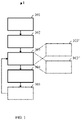
- FIG. 1 illustrates a flow diagram of a method 1 according to a first aspect of the present disclosure
- FIG. 2 illustrates resultant curves of a voltage 5 and a current 6 of an exemplary battery 4 when carrying out the method 1 of FIG. 1 .
- the method 1 is for operating a battery charger 2 for a Lithium-based battery 4 comprising a cell.
- the Lithium-based battery 4 may comprise a Lithium-ion cell or a Lithium ferro-phosphate (LFP) cell.
- the battery 4 may comprise a number S of stages in series each having a number P of cells in parallel.
- the method 1 comprises a step of connecting 101 the battery 4 to a powered battery charger 2, such as the one illustrated in FIG. 3 and explained in more detail below.
- the method 1 further comprises, responsive to the voltage 5, V CELL of the cell being below a threshold voltage 501, V T , a step of applying 102 a constant charging current 601, I CC to the cell until a charging power V CELL ⁇ I CC is equal to or above a target power V T ⁇ I CC .
- This may also be taken from the CC charging phase indicated in FIG. 2 , where the applied constant charging current 601, Icc results in a rising voltage 5, V CELL of the cell until the voltage 5, V CELL of the cell equals the threshold voltage 501, V T , and thus the charging power V CELL ⁇ I CC equals the target power V T ⁇ I CC .
- the threshold voltage 501, V T may comprise 24/27, preferably 22/27, and most preferably 20/27 of a maximum charging voltage 502, V MAX , such as 3,6 V per cell.
- the constant charging current 601, Icc may depend on at least one of a minimum rated capacity of the battery 4, and a production tolerance of the minimum rated capacity.
- V CELL of the cell isn't the nominal / working voltage of 3,2V when charging, the required rated capacity or energy may need to be adjusted to even higher values, such as 5% higher. In any case, CP charging may still result in about 5-7% less peak charging power than CC charging.
- the charging current 6, I CELL may be equal to or below the threshold current 602, I T within a maximum recharge time defined by relevant standards, e.g. 24 hours, responsive to the voltage 5, V CELL of the cell being equal to or below the threshold voltage 501, V T . In other words, it must not take longer than said maximum recharge time such as 24 h to fully recharge the battery 4 of an emergency lighting product when recognizing that recharging is necessary (undershoot of threshold voltage 501, V T ), in accordance with a pertinent standard.
- relevant standards e.g. 24 hours
- the constant charging current 601, I CC may exceed a constant charging current 601, I CC of known CC-CV LFP battery chargers, but without exceeding the target power V T ⁇ I CC . This makes sense because when maintaining the requirement of full recharging within the maximum recharge time of e.g. 24 h, reducing a (maximum) charging power in one phase of a charging procedure requires increasing a charging power in another phase of charging procedure in exchange.
- the method 1 further comprises a step of applying 103 a charging current 6, I CELL lower than the constant charging current 601, I CC to the cell until the voltage 5, V CELL of the cell is equal to or above a maximum charging voltage 502, V MAX .
- This may also be taken from the CP charging phase indicated in FIG. 2 , where the curve of the charging current 6, I CELL decreases from the constant charging current 601, Icc until the voltage 5, V CELL of the cell equals the maximum charging voltage 502, V MAX
- the step of applying 103 of the charging current 6, I CELL lower than the constant charging current 601, I CC to the cell may comprise a step of applying 103' a charging current 6, I CELL decreasing in dependence of the voltage 5, V CELL of the cell in the CP charging phase.
- the step of applying 103, 103' of the charging current 6, I CELL lower than the constant charging current 601, I CC to the cell may comprise a step of applying the target power V T ⁇ I CC to the cell.
- a constant target power V T ⁇ I CC may be applied to the cell in the CP charging phase.
- the method 1 further comprises a step of applying 104 the maximum charging voltage 502, V MAX to the cell until the charging current 6, I CELL is equal to or below a threshold current 602, I T .
- This may also be taken from the CV charging phase indicated in FIG. 2 , where the applied constant maximum charging voltage 502, V MAX results in the charging current 6, I CELL decreasing until it equals the threshold current 602, I T . This should be the case within the maximum recharge time of e.g. 24 h, as already explained.
- the threshold current 602, I T may comprise 3/9, preferably 2/9, and most preferably 1/9 of the constant charging current 601, I CC .
- I CC constant charging current 601, I CC of 450 mA (i.e., per parallel branch of the battery configuration)
- the method 1 may further comprise, responsive to the voltage 5, V CELL of the cell being equal to or below a further threshold voltage 503, V T2 , triggering 105 the applying 103 of the charging current 6, I CELL lower than the constant charging current 601, Icc to the cell.
- V CELL of the cell decreases to the further threshold voltage 503, V T2 , owing to self-discharge of the cell, recharging is initiated by starting the CP charging phase.
- the further threshold voltage 503, V T2 may comprise 15/18, preferably 16/18, and most preferably 17/18 of the maximum charging voltage 502, V MAX .
- FIG. 3 illustrates a battery charger 2 according to a second aspect of the present disclosure.
- the battery charger 2 is for a Lithium-based battery 4 comprising a cell.
- the battery charger 2 comprises input terminals 201 connected to a source of electrical power, such as the AC power grid indicated in FIG. 2 , and output terminals 202 connected to the battery 4.
- a power converter 203, 204 interconnecting the input terminals 201 and the output terminals 202 is also provided.
- the power converter 203, 204 comprises an AC/DC converter 203 such as a flyback converter at a front-end and supplied via the input terminals 201, and may comprise a DC/DC converter 204 such as a buck converter at a back-end and supplied by the AC/DC converter 203.
- the DC/DC converter 204 isn't necessarily required as long as battery current and voltage can be sensed and a battery current can be controlled accordingly.
- the battery 4 is in turn supplied by the DC/DC converter 204 via the output terminals 202.
- a resistor is arranged as one of the many possible implementations for current sensing purposes.
- the battery charger 2 further comprises a controller unit 205, such as a microcontroller.
- the controller unit 205 is configured to measure a voltage 5, V CELL of the cell and/or the battery 4, a charging current 6, I CELL of the cell and/or the battery 4, and thus a charging power of the cell and/or the battery 4.
- the controller unit 205 is further configured to control the charging current 6, I CELL of the cell and/or the battery 4 supplied by the DC/DC converter 204 via the output terminals 202.
- the controller unit 205 is configured, responsive to the voltage 5, V CELL of the cell being below a threshold voltage 501, V T , to apply 102 a constant charging current 601, I CC to the cell until the charging power V CELL ⁇ I CC is equal to or above a target power V T ⁇ I CC .
- the controller unit 205 is further configured to apply 103 a charging current 6, I CELL lower than the constant charging current 601, Icc to the cell until the voltage 5, V CELL of the cell is equal to or above a maximum charging voltage 502, V MAX
- the controller unit 205 is further configured to apply 104 the maximum charging voltage 502, V MAX to the cell until the charging current 6, I CELL is equal to or below a threshold current 602, I T .
- the controller unit 205 may further be configured to carry out the method 1 of the first aspect or any of its embodiments of operating the battery charger 2.
- FIG. 3 further illustrates an emergency power supply 3 according to a third aspect of the present disclosure.
- the emergency power supply 3 is for an LED lighting system and comprises a Lithium-based battery 4 comprising a cell and a battery charger 2 of the second aspect or any of its embodiments.
Landscapes
- Engineering & Computer Science (AREA)
- Power Engineering (AREA)
- Manufacturing & Machinery (AREA)
- Chemical & Material Sciences (AREA)
- Chemical Kinetics & Catalysis (AREA)
- Electrochemistry (AREA)
- General Chemical & Material Sciences (AREA)
- Charge And Discharge Circuits For Batteries Or The Like (AREA)
- Secondary Cells (AREA)
Abstract
Description
- The present invention relates to charging of Lithium-based batteries, and in particular to a method of operating a battery charger for a Lithium-based battery, a corresponding battery charger, and an emergency power supply for an LED lighting system comprising a Lithium-based battery and a battery charger.
- In the context of emergency lighting, rechargeable Lithium-based batteries have grown in popularity owing to high energy density, low self-discharge and absent memory effect.
- Charging of Lithium-based batteries typically involves constant current - constant voltage (CC-CV) algorithms. When adopting the CC-CV approach, the charger electronics and consequently the emergency lighting product must be validated thermally at worst-case power conditions (i.e., at Pmax = Vmax ·Imax ). The electronic components are thus subject to high power ratings and high peak temperatures that shorten their lifetime.
- The object of the present invention is to loosen a worst-case power condition of a battery charger for Lithium-based batteries.
- The invention is defined by the appended independent claims. Preferred embodiments are set forth in the dependent claims and in the following description and drawings.
- According to a first aspect of the present disclosure, a method of operating a battery charger is provided. The method is for a Lithium-based battery comprising a cell and comprises: connecting the battery to a powered battery charger; responsive to a voltage of the cell being below a threshold voltage , applying a constant charging current to the cell until a charging power is equal to or above a target power; applying a charging current lower than the constant charging current to the cell until the voltage of the cell is equal to or above a maximum charging voltage; and applying the maximum charging voltage to the cell until the charging current is equal to or below a threshold current.
- In an implementation of the first aspect, the applying of the charging current lower than the constant charging current to the cell may comprise: applying a charging current decreasing in dependence of the voltage of the cell.
- In an implementation of the first aspect, the applying of the charging current lower than the constant charging current to the cell may comprise: applying the target power to the cell.
- In an implementation of the first aspect, the method may further comprise responsive to the voltage of the cell being equal to or below a further threshold voltage, triggering the applying of the charging current lower than the constant charging current to the cell.
- In an implementation of the first aspect, the further threshold voltage may comprise 15/18, preferably 16/18, and most preferably 17/18 of the maximum charging voltage.
- In an implementation of the first aspect, the constant charging current may depend on at least one of a minimum rated capacity of the battery, and a production tolerance of the minimum rated capacity.
- In an implementation of the first aspect, the constant charging current may exceed a constant charging current of known CC-CV LFP battery chargers.
- In an implementation of the first aspect, the threshold current may comprise 3/9, preferably 2/9, and most preferably 1/9 of the constant charging current.
- In an implementation of the first aspect, the threshold voltage may comprise 24/27, preferably 22/27, and most preferably 20/27 of a maximum charging voltage of the maximum charging voltage.
- In an implementation of the first aspect, the battery may comprise a number of stages in series each having a number of cells in parallel.
- In an implementation of the first aspect, the target power may depend on the number of stages.
- In an implementation of the first aspect, responsive to the voltage of the cell being equal to or below the threshold voltage, the charging current may be equal to or below the threshold current within a maximum recharge time defined by relevant standards, e.g. 24 hours.
- In an implementation of the first aspect, the Lithium-based battery may comprise a Lithium ion cell or a Lithium ferro-phosphate cell.
- According to a second aspect of the present disclosure, a battery charger for a Lithium-based battery comprising a cell is provided. The battery charger comprises: input terminals connectable to a source of electrical power; output terminals connectable to the battery; a power converter interconnecting the input terminals and the output terminals; and a controller unit. The controller unit is configured to measure a voltage of the cell, a charging current and a charging power of the battery. The controller unit is configured to, responsive to the voltage of the cell being below a threshold voltage , apply a constant charging current to the cell until the charging power is equal to or above a target power. The controller unit is configured to apply a charging current lower than the constant charging current to the cell until the voltage of the cell is equal to or above a maximum charging voltage. The controller unit is configured to apply the maximum charging voltage to the cell until the charging current is equal to or below a threshold current.
- In an implementation of the second aspect, the controller unit may further be configured to carry out the method of the first aspect or any of its embodiments of operating the battery charger.
- According to a third aspect of the present disclosure, an emergency power supply for an LED lighting system is provided. The emergency power supply comprises: a Lithium-based battery comprising a cell; and a battery charger of the second aspect or any of its embodiments.
- The present invention provides a method, a battery charger and an emergency power supply implementing a CC-CP-CV charging algorithm which, by applying a substantially constant power (CP), reduces a worst-case charging power in relation to known CC-CV charging algorithms. Accordingly, the electronic components of the battery charger are subjected to lower peak temperatures, may thus be selected in accordance with lower power ratings, and serve for a prolonged lifetime in a safer design. The CC-CP-CV charging regime is applicable to Lithium ferro-phosphate as well as other lithium-based batteries such as Lithium Titanate Oxide, Nickel Manganese Cobalt, Lithium Cobalt Oxide.
- Further aspects, advantages and objects of the invention will become evident for the skilled reader by means of the following detailed description of the embodiments of the invention, when taking into conjunction with the figures of the enclosed drawings.
-
FIG. 1 illustrates a flow diagram of a method according to a first aspect of the present disclosure; -
FIG. 2 illustrates resultant curves of avoltage 5 and a current 6 of anexemplary battery 4 when carrying out the method 1 ofFIG. 1 . -
FIG. 3 illustrates a battery charger according to a second aspect of the present disclosure, and an emergency power supply according to a third aspect of the present disclosure. - The invention will now be described with respect to various embodiments. The features of these embodiments may be combined with each other unless specified otherwise.
-
FIG. 1 illustrates a flow diagram of a method 1 according to a first aspect of the present disclosure, andFIG. 2 illustrates resultant curves of avoltage 5 and a current 6 of anexemplary battery 4 when carrying out the method 1 ofFIG. 1 . - The method 1 is for operating a battery charger 2 for a Lithium-based
battery 4 comprising a cell. - The Lithium-based
battery 4 may comprise a Lithium-ion cell or a Lithium ferro-phosphate (LFP) cell. Thebattery 4 may comprise a number S of stages in series each having a number P of cells in parallel. For example, common battery configurations comprise 2s1p, 2s2p, 3s1p or 3s2p, corresponding to {S=2;P=1}, {S=2;P=2}, {S=3;P=1} or {S=3;P=2}, respectively. - The method 1 comprises a step of connecting 101 the
battery 4 to a powered battery charger 2, such as the one illustrated inFIG. 3 and explained in more detail below. - The method 1 further comprises, responsive to the
voltage 5, VCELL of the cell being below athreshold voltage 501, VT , a step of applying 102 aconstant charging current 601, ICC to the cell until a charging power VCELL ·ICC is equal to or above a target power VT ·ICC. This may also be taken from the CC charging phase indicated inFIG. 2 , where the appliedconstant charging current 601, Icc results in a risingvoltage 5, VCELL of the cell until thevoltage 5, VCELL of the cell equals thethreshold voltage 501, VT, and thus the charging power VCELL ·ICC equals the target power VT ·ICC. - The
threshold voltage 501, VT may comprise 24/27, preferably 22/27, and most preferably 20/27 of amaximum charging voltage 502, VMAX , such as 3,6 V per cell. - For example, in a 2slp battery configuration, the
maximum charging voltage 502, VMAX and thecorresponding threshold voltage 501, VT may amount to 2·3,6 V = 7,2 V and 2·3,6 V·20/27 = 5,33 V. - The
constant charging current 601, Icc may depend on at least one of a minimum rated capacity of thebattery 4, and a production tolerance of the minimum rated capacity. - For example, a minimum rated capacity of a cell of 1,5Ah and a production tolerance (overcapacity) of +20% amounts to a rated capacity of 1,5Ah... 1,5Ah·(1+20%) = 1,5... 1,8Ah. In connection with an exemplary nominal / working voltage of 3,2V per cell a rated energy amounts to (1,5...1,8Ah)·3,2V = 4,8... 5,76Wh. This corresponds to a charging current 6, ICELL of 62,5... 75 mA over a maximum recharge time of 24 h, or a charging power of 0, 20...0,24W over 24 h. As the
average voltage 5, VCELL of the cell isn't the nominal / working voltage of 3,2V when charging, the required rated capacity or energy may need to be adjusted to even higher values, such as 5% higher. In any case, CP charging may still result in about 5-7% less peak charging power than CC charging. - The charging current 6, ICELL may be equal to or below the threshold current 602, IT within a maximum recharge time defined by relevant standards, e.g. 24 hours, responsive to the
voltage 5, VCELL of the cell being equal to or below thethreshold voltage 501, VT. In other words, it must not take longer than said maximum recharge time such as 24 h to fully recharge thebattery 4 of an emergency lighting product when recognizing that recharging is necessary (undershoot ofthreshold voltage 501, VT ), in accordance with a pertinent standard. - The constant charging current 601, ICC may exceed a constant charging current 601, ICC of known CC-CV LFP battery chargers, but without exceeding the target power VT ·ICC. This makes sense because when maintaining the requirement of full recharging within the maximum recharge time of e.g. 24 h, reducing a (maximum) charging power in one phase of a charging procedure requires increasing a charging power in another phase of charging procedure in exchange.
- The target power VT ·ICC may depend on the number S of stages. This makes sense because the
threshold voltage 501, VT itself is proportional to the number S of stages, as already exemplified above: VT = S·3,6 V. - The method 1 further comprises a step of applying 103 a charging current 6, ICELL lower than the constant charging current 601, ICC to the cell until the
voltage 5, VCELL of the cell is equal to or above amaximum charging voltage 502, VMAX. This may also be taken from the CP charging phase indicated inFIG. 2 , where the curve of the charging current 6, ICELL decreases from the constant charging current 601, Icc until thevoltage 5, VCELL of the cell equals themaximum charging voltage 502, VMAX - The step of applying 103 of the charging current 6, ICELL lower than the constant charging current 601, ICC to the cell may comprise a step of applying 103' a charging current 6, ICELL decreasing in dependence of the
voltage 5, VCELL of the cell in the CP charging phase. - The step of applying 103, 103' of the charging current 6, ICELL lower than the constant charging current 601, ICC to the cell may comprise a step of applying the target power VT ·ICC to the cell. In other words, a constant target power VT ·ICC may be applied to the cell in the CP charging phase.
- The method 1 further comprises a step of applying 104 the
maximum charging voltage 502, VMAX to the cell until the charging current 6, ICELL is equal to or below a threshold current 602, IT. This may also be taken from the CV charging phase indicated inFIG. 2 , where the applied constantmaximum charging voltage 502, VMAX results in the charging current 6, ICELL decreasing until it equals the threshold current 602, IT. This should be the case within the maximum recharge time of e.g. 24 h, as already explained. - The threshold current 602, IT may comprise 3/9, preferably 2/9, and most preferably 1/9 of the constant charging current 601, ICC. For example, given a constant charging current 601, ICC of 450 mA (i.e., per parallel branch of the battery configuration), the threshold current 602, IT may amount to 1/9·450 mA = 50 mA.
- The method 1 may further comprise, responsive to the
voltage 5, VCELL of the cell being equal to or below a further threshold voltage 503, VT2, triggering 105 the applying 103 of the charging current 6, ICELL lower than the constant charging current 601, Icc to the cell. In other words, if thevoltage 5, VCELL of the cell decreases to the further threshold voltage 503, VT2, owing to self-discharge of the cell, recharging is initiated by starting the CP charging phase. - The further threshold voltage 503, VT2 may comprise 15/18, preferably 16/18, and most preferably 17/18 of the
maximum charging voltage 502, VMAX . For example, in a 2s1p battery configuration, the further threshold voltage 503, VT2 may amount to 17/18 · VMAX = 17/18·2·3,6 V = 6,8 V. -
FIG. 3 illustrates a battery charger 2 according to a second aspect of the present disclosure. - The battery charger 2 is for a Lithium-based
battery 4 comprising a cell. - The battery charger 2 comprises
input terminals 201 connected to a source of electrical power, such as the AC power grid indicated inFIG. 2 , andoutput terminals 202 connected to thebattery 4. Apower converter input terminals 201 and theoutput terminals 202 is also provided. In the example ofFIG. 3 , thepower converter DC converter 203 such as a flyback converter at a front-end and supplied via theinput terminals 201, and may comprise a DC/DC converter 204 such as a buck converter at a back-end and supplied by the AC/DC converter 203. The DC/DC converter 204 isn't necessarily required as long as battery current and voltage can be sensed and a battery current can be controlled accordingly. Thebattery 4 is in turn supplied by the DC/DC converter 204 via theoutput terminals 202. On a low side of theoutput terminals 202, a resistor is arranged as one of the many possible implementations for current sensing purposes. - With continuing reference to
FIG.3 , the battery charger 2 further comprises acontroller unit 205, such as a microcontroller. - The
controller unit 205 is configured to measure avoltage 5, VCELL of the cell and/or thebattery 4, a charging current 6, ICELL of the cell and/or thebattery 4, and thus a charging power of the cell and/or thebattery 4. - The
controller unit 205 is further configured to control the charging current 6, ICELL of the cell and/or thebattery 4 supplied by the DC/DC converter 204 via theoutput terminals 202. - As such, the
controller unit 205 is configured, responsive to thevoltage 5, VCELL of the cell being below athreshold voltage 501, VT, to apply 102 a constant charging current 601, ICC to the cell until the charging power VCELL ·ICC is equal to or above a target power VT ·ICC. - The
controller unit 205 is further configured to apply 103 a charging current 6, ICELL lower than the constant charging current 601, Icc to the cell until thevoltage 5, VCELL of the cell is equal to or above amaximum charging voltage 502, VMAX - The
controller unit 205 is further configured to apply 104 themaximum charging voltage 502, VMAX to the cell until the charging current 6, ICELL is equal to or below a threshold current 602, IT. - The
controller unit 205 may further be configured to carry out the method 1 of the first aspect or any of its embodiments of operating the battery charger 2. -
FIG. 3 further illustrates an emergency power supply 3 according to a third aspect of the present disclosure. - The emergency power supply 3 is for an LED lighting system and comprises a Lithium-based
battery 4 comprising a cell and a battery charger 2 of the second aspect or any of its embodiments.
Claims (15)
- A method (1) of operating a battery charger (2) for a Lithium-based battery (4) comprising a cell (401),
the method (1) comprisingconnecting (101) the battery (4) to a powered battery charger (2);responsive to a voltage (5, VCELL ) of the cell (401) being below a threshold voltage (501, VT ), applying (102) a constant charging current (601, ICC ) to the cell (401) until a charging power (VCELL ·ICC ) is equal to or above a target power (VT·ICC );applying (103) a charging current (6, ICELL ) lower than the constant charging current (601, ICC ) to the cell (401) until the voltage (5, VCELL ) of the cell (401) is equal to or above a maximum charging voltage (502, VMAX ); andapplying (104) the maximum charging voltage (502, VMAX ) to the cell (401) until the charging current (6, ICELL ) is equal to or below a threshold current (602, IT ). - The method (1) of claim 1,
the applying (103) of the charging current (6, ICELL ) lower than the constant charging current (601, ICC ) to the cell (401) comprising
applying (103') a charging current (6, ICELL ) decreasing in dependence of the voltage (5, VCELL ) of the cell (401). - The method (1) of claim 1 or claim 2,
the applying (103, 103') of the charging current (6, ICELL ) lower than the constant charging current (601, ICC ) to the cell (401) comprising
applying the target power (VT ·ICC ) to the cell (401). - The method (1) of any of the preceding claims, further comprising
responsive to the voltage (5, VCELL ) of the cell (401) being equal to or below a further threshold voltage (503, VT2 ), triggering (105) the applying (103) of the charging current (6, ICELL ) lower than the constant charging current (601, ICC ) to the cell (401). - The method (1) of claim 4,
the further threshold voltage (503, VT2 ) comprising 15/18, preferably 16/18, and most preferably 17/18 of the maximum charging voltage (502, VMAX ). - The method (1) of any of the preceding claims,
the constant charging current (601, ICC ) depending on at least one ofa minimum rated capacity of the battery (4), anda production tolerance of the minimum rated capacity. - The method (1) of claim 6,
the constant charging current (601, ICC ) exceeding a constant charging current of known CC-CV LFP battery chargers. - The method (1) of any of the preceding claims,
the threshold current comprising 3/9, preferably 2/9, and most preferably 1/9 of the constant charging current (601, ICC ). - The method (1) of any of the preceding claims,
the threshold voltage (501, VT ) comprising 24/27, preferably 22/27, and most preferably 20/27 of the maximum charging voltage (502, VMAX ). - The method (1) of any of the preceding claims,the battery (4) comprising a number (S) of stages in series each having a number (P) of cells (401) in parallel, andthe target power (VT ·ICC ) depending on the number (S) of stages.
- The method (1) of any of the preceding claims,
the charging current (6, ICELL ) being equal to or below the threshold current (IT) within a maximum recharge time defined by relevant standards responsive to the voltage (5, VCELL ) of the cell (401) being equal to or below the threshold voltage (501, VT ). - The method (1) of any of the preceding claims,
the Lithium-based battery (4) comprising a Lithium ion cell (401) or a Lithium ferrophosphate (LFP) cell (401). - A battery charger (2) for a Lithium-based battery (4) comprising a cell (401), the battery charger (2) comprisinginput terminals (201)
connectable to a source of electrical power;output terminals (202)
connectable to the battery (4);a power converter (203, 204)
interconnecting the input terminals (201) and the output terminals (202); anda controller unit (205)configured to measure a voltage (5, VCELL ) of the cell (401), a charging current (6, ICELL ) and a charging power of the battery (4);configured to, responsive to the voltage (5, VCELL ) of the cell (401) being below a threshold voltage (501, VT ), apply (102) a constant charging current (601, ICC ) to the cell (401) until the charging power is equal to or above a target power (VT·ICC );configured to apply (103) a charging current (6, ICELL ) lower than the constant charging current (601, ICC ) to the cell (401) until the voltage (5, VCELL ) of the cell (401) is equal to or above a maximum charging voltage (502, VMAX ); andconfigured to apply (104) the maximum charging voltage (502, VMAX ) to the cell (401) until the charging current (6, ICELL ) is equal to or below a threshold current. - The battery charger (2) of claim 13,
the controller unit (205)
further configured to carry out the method (1) of any of the preceding claims of operating the battery charger (2). - An emergency power supply (3) for an LED lighting system, comprisinga Lithium-based battery (4) comprising a cell (401); anda battery charger (2) of claim 13 or claim 14.
Priority Applications (2)
| Application Number | Priority Date | Filing Date | Title |
|---|---|---|---|
| EP21158602.9A EP4047778A1 (en) | 2021-02-23 | 2021-02-23 | Cc-cp-cv charging of lithium-based batteries |
| PCT/EP2022/053328 WO2022179862A1 (en) | 2021-02-23 | 2022-02-11 | Cc-cp-cv charging of lithium-based batteries |
Applications Claiming Priority (1)
| Application Number | Priority Date | Filing Date | Title |
|---|---|---|---|
| EP21158602.9A EP4047778A1 (en) | 2021-02-23 | 2021-02-23 | Cc-cp-cv charging of lithium-based batteries |
Publications (1)
| Publication Number | Publication Date |
|---|---|
| EP4047778A1 true EP4047778A1 (en) | 2022-08-24 |
Family
ID=74701403
Family Applications (1)
| Application Number | Title | Priority Date | Filing Date |
|---|---|---|---|
| EP21158602.9A Pending EP4047778A1 (en) | 2021-02-23 | 2021-02-23 | Cc-cp-cv charging of lithium-based batteries |
Country Status (2)
| Country | Link |
|---|---|
| EP (1) | EP4047778A1 (en) |
| WO (1) | WO2022179862A1 (en) |
Cited By (1)
| Publication number | Priority date | Publication date | Assignee | Title |
|---|---|---|---|---|
| CN115395626A (en) * | 2022-10-27 | 2022-11-25 | 苏州智绿环保科技有限公司 | Fill on cable control connection circuit who fills an organic whole and adaptation circuit thereof |
Citations (4)
| Publication number | Priority date | Publication date | Assignee | Title |
|---|---|---|---|---|
| US6087810A (en) * | 1995-10-24 | 2000-07-11 | Matsushita Electric Industrial Co., Ltd. | Constant current and constant voltage battery charger |
| US20100102778A1 (en) * | 2007-02-19 | 2010-04-29 | Takahisa Otsu | Charging system, charger, and battery pack |
| EP2365605A2 (en) * | 2010-02-26 | 2011-09-14 | Sanyo Electric Co., Ltd. | Charging apparatus, program |
| EP3663781A1 (en) * | 2018-12-06 | 2020-06-10 | Tridonic GmbH & Co. KG | Charge monitor, charger and charge monitoring method based on recharge frequency |
-
2021
- 2021-02-23 EP EP21158602.9A patent/EP4047778A1/en active Pending
-
2022
- 2022-02-11 WO PCT/EP2022/053328 patent/WO2022179862A1/en not_active Ceased
Patent Citations (4)
| Publication number | Priority date | Publication date | Assignee | Title |
|---|---|---|---|---|
| US6087810A (en) * | 1995-10-24 | 2000-07-11 | Matsushita Electric Industrial Co., Ltd. | Constant current and constant voltage battery charger |
| US20100102778A1 (en) * | 2007-02-19 | 2010-04-29 | Takahisa Otsu | Charging system, charger, and battery pack |
| EP2365605A2 (en) * | 2010-02-26 | 2011-09-14 | Sanyo Electric Co., Ltd. | Charging apparatus, program |
| EP3663781A1 (en) * | 2018-12-06 | 2020-06-10 | Tridonic GmbH & Co. KG | Charge monitor, charger and charge monitoring method based on recharge frequency |
Cited By (1)
| Publication number | Priority date | Publication date | Assignee | Title |
|---|---|---|---|---|
| CN115395626A (en) * | 2022-10-27 | 2022-11-25 | 苏州智绿环保科技有限公司 | Fill on cable control connection circuit who fills an organic whole and adaptation circuit thereof |
Also Published As
| Publication number | Publication date |
|---|---|
| WO2022179862A1 (en) | 2022-09-01 |
Similar Documents
| Publication | Publication Date | Title |
|---|---|---|
| CN101345432B (en) | How to charge the battery pack | |
| US8922063B2 (en) | Circuit for rendering energy storage devices parallelable | |
| US8193778B2 (en) | Method of charging a battery array | |
| CN101953016B (en) | Charging method for an assembled cell and an assembled cell system | |
| US7902796B2 (en) | Battery equalization charging method and apparatus | |
| US8294425B2 (en) | Charging apparatus and charge control method | |
| Yu et al. | Balanced discharging for serial battery power modules with boost converters | |
| US20110210701A1 (en) | Battery system | |
| CN106374560A (en) | Rapid charging method of parallel battery pack and related equipment | |
| CN103081282A (en) | Power management system | |
| JP2015202024A (en) | mobile battery | |
| US20230216335A1 (en) | Energy storage system and power supply method thereof | |
| WO2022178839A1 (en) | Energy system, and charging and discharging control method | |
| CN103227487A (en) | Fuel cell/lithium ion battery hybrid power energy management system used for electric bicycle | |
| CN110838746A (en) | A battery parallel circuit and battery parallel device | |
| EP4047778A1 (en) | Cc-cp-cv charging of lithium-based batteries | |
| Maheswaran et al. | Study and implementation of constant current-constant voltage (CC-CV) charger for lithium-Ion (Li-Ion) battery using machine learning (ML) | |
| KR20230068380A (en) | Portable electric vehicle battery charger | |
| JP2001268815A (en) | Charging circuit | |
| US11095133B2 (en) | Simple battery and charger system | |
| JP2002238179A (en) | Rechargeable battery charger and charging method | |
| EP4443695A1 (en) | Method of smart battery control | |
| Siddeshkumar et al. | Advanced Optimized Active Cell Balancing with Efficient Power Electronics Algorithms for Superior Battery Performance in Electric Vehicle | |
| CN110034590A (en) | Power type accumulator battery can be changed isolated form charge equalization unit | |
| US12322993B2 (en) | Battery charger with a plurality of secondary transformer circuits |
Legal Events
| Date | Code | Title | Description |
|---|---|---|---|
| PUAI | Public reference made under article 153(3) epc to a published international application that has entered the european phase |
Free format text: ORIGINAL CODE: 0009012 |
|
| STAA | Information on the status of an ep patent application or granted ep patent |
Free format text: STATUS: THE APPLICATION HAS BEEN PUBLISHED |
|
| AK | Designated contracting states |
Kind code of ref document: A1 Designated state(s): AL AT BE BG CH CY CZ DE DK EE ES FI FR GB GR HR HU IE IS IT LI LT LU LV MC MK MT NL NO PL PT RO RS SE SI SK SM TR |
|
| STAA | Information on the status of an ep patent application or granted ep patent |
Free format text: STATUS: REQUEST FOR EXAMINATION WAS MADE |
|
| 17P | Request for examination filed |
Effective date: 20230109 |
|
| RBV | Designated contracting states (corrected) |
Designated state(s): AL AT BE BG CH CY CZ DE DK EE ES FI FR GB GR HR HU IE IS IT LI LT LU LV MC MK MT NL NO PL PT RO RS SE SI SK SM TR |