EP4047745A1 - Antenna and electronic device - Google Patents
Antenna and electronic device Download PDFInfo
- Publication number
- EP4047745A1 EP4047745A1 EP20881076.2A EP20881076A EP4047745A1 EP 4047745 A1 EP4047745 A1 EP 4047745A1 EP 20881076 A EP20881076 A EP 20881076A EP 4047745 A1 EP4047745 A1 EP 4047745A1
- Authority
- EP
- European Patent Office
- Prior art keywords
- radiator
- antenna
- coupler
- plate body
- radiators
- Prior art date
- Legal status (The legal status is an assumption and is not a legal conclusion. Google has not performed a legal analysis and makes no representation as to the accuracy of the status listed.)
- Granted
Links
Images

Classifications
-
- H—ELECTRICITY
- H01—ELECTRIC ELEMENTS
- H01Q—ANTENNAS, i.e. RADIO AERIALS
- H01Q5/00—Arrangements for simultaneous operation of antennas on two or more different wavebands, e.g. dual-band or multi-band arrangements
- H01Q5/30—Arrangements for providing operation on different wavebands
- H01Q5/378—Combination of fed elements with parasitic elements
- H01Q5/385—Two or more parasitic elements
-
- H—ELECTRICITY
- H01—ELECTRIC ELEMENTS
- H01Q—ANTENNAS, i.e. RADIO AERIALS
- H01Q1/00—Details of, or arrangements associated with, antennas
- H01Q1/36—Structural form of radiating elements, e.g. cone, spiral, umbrella; Particular materials used therewith
- H01Q1/38—Structural form of radiating elements, e.g. cone, spiral, umbrella; Particular materials used therewith formed by a conductive layer on an insulating support
-
- H—ELECTRICITY
- H01—ELECTRIC ELEMENTS
- H01Q—ANTENNAS, i.e. RADIO AERIALS
- H01Q21/00—Antenna arrays or systems
- H01Q21/24—Combinations of antenna units polarised in different directions for transmitting or receiving circularly and elliptically polarised waves or waves linearly polarised in any direction
-
- H—ELECTRICITY
- H01—ELECTRIC ELEMENTS
- H01Q—ANTENNAS, i.e. RADIO AERIALS
- H01Q1/00—Details of, or arrangements associated with, antennas
- H01Q1/50—Structural association of antennas with earthing switches, lead-in devices or lightning protectors
-
- H—ELECTRICITY
- H01—ELECTRIC ELEMENTS
- H01Q—ANTENNAS, i.e. RADIO AERIALS
- H01Q21/00—Antenna arrays or systems
- H01Q21/06—Arrays of individually energised antenna units similarly polarised and spaced apart
- H01Q21/08—Arrays of individually energised antenna units similarly polarised and spaced apart the units being spaced along or adjacent to a rectilinear path
-
- H—ELECTRICITY
- H01—ELECTRIC ELEMENTS
- H01Q—ANTENNAS, i.e. RADIO AERIALS
- H01Q5/00—Arrangements for simultaneous operation of antennas on two or more different wavebands, e.g. dual-band or multi-band arrangements
- H01Q5/40—Imbricated or interleaved structures; Combined or electromagnetically coupled arrangements, e.g. comprising two or more non-connected fed radiating elements
Definitions
- the present invention relates to the field of communications technologies, and in particular, to an antenna and an electronic device.
- Millimeter-wave antennas can provide a higher communication speed, lower latency, more simultaneous connections, and the like, bringing greater convenience to users' life.
- Embodiments of the present invention provide an antenna and an electronic device, to resolve a problem that radiation performance of a millimeter-wave antenna is relatively low.
- an embodiment of the present invention provides an antenna, including a plate body, where the plate body is provided with at least one antenna element, each antenna element includes a groove formed in the plate body, a coupling frame body formed in the plate body, four radiators formed in the plate body, four coupling bodies formed in the plate body, and four electric conductors formed in the plate body, the four radiators and the four couplers are all disposed in a space enclosed by the coupling frame body, the coupling frame body is disposed in the groove, each radiator is provided with a feed point, the different electric conductors penetrate through the groove bottom of the groove and are respectively connected to the feed points on the different radiators, and the four radiators are connected to the four electric conductors in a one-to-one correspondence;
- an embodiment of the present invention provides an electronic device, including the foregoing antenna, where the electronic device further includes a metal frame, and the plate body of the antenna is a portion of the metal frame.
- An antenna provided in the embodiments of the present invention includes a plate body, where the plate body is provided with at least one antenna element, each antenna element includes a groove formed in the plate body, a coupling frame body formed in the plate body, four radiators formed in the plate body, four coupling bodies formed in the plate body, and four electric conductors formed in the plate body, the four radiators and the four couplers are all disposed in a space enclosed by the coupling frame body, the coupling frame body is disposed in the groove, each radiator is provided with a feed point, the different electric conductors penetrate through the groove bottom of the groove and are respectively connected to the feed points on the different radiators, and the four radiators are connected to the four electric conductors in a one-to-one correspondence; the four radiators access two pairs of differential signals; and the plate body, the coupling frame body, the four radiators, and the four couplers are not in contact with one another, an insulating medium is filled between the plate body, the coupling frame body, the four radiators, and the four couple
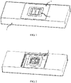
- FIG. 1 to FIG. 3 are all schematic structural diagrams of an antenna according to an embodiment of the present invention.
- the antenna includes a plate body 1, where the plate body 1 is provided with at least one antenna element, and each antenna element includes a groove formed in the plate body 1, a coupling frame body 2 formed in the plate body 1, four radiators 3 formed in the plate body 1, four coupling bodies 4 formed in the plate body 1, and four electric conductors formed in the plate body 1.
- the four radiators 3 and the four couplers 4 are all disposed in a space enclosed by the coupling frame body 2.
- the coupling frame body 2 is disposed in the groove.
- Each radiator 3 is provided with a feed point.
- the different electric conductors penetrate through the groove bottom of the groove and are respectively connected to the feed points on the different radiators.
- the four radiators 3 are connected to the four electric conductors in a one-to-one correspondence.
- the four radiators 3 access two pairs of differential signals.
- the plate body 1, the coupling frame body 2, the four radiators 3, and the four couplers 4 are not in contact with one another, and an insulating medium 5 is filled between the plate body 1, the coupling frame body 2, the four radiators 3, and the four couplers 4.
- the four electric conductors are insulated from the groove bottom of the groove.
- FIG. 1 is a schematic structural diagram of an antenna with a groove being filled with an insulating medium 5
- FIG. 2 is a schematic structural diagram of an antenna with a groove from which an insulating medium 5 is removed.
- the foregoing antenna element may be a millimeter-wave antenna element.
- the foregoing groove may be a rectangular groove.
- the foregoing coupling frame body 2 may be a rectangular frame body.
- the foregoing radiators 3 may be T-shaped.
- the foregoing couplers 4 may be strip-shaped.
- the foregoing four radiators 3 and four couplers 4 may be disposed in layers in the space.
- two radiators 3 and two couplers 4 are disposed in a first layer in the space, and the other two radiators 3 and the other two couplers 4 are disposed in a second layer in the space.
- the four radiators 3 may include a first radiator 31, a second radiator 32, a third radiator 33, and a fourth radiator 34.
- the four couplers 4 may include a first coupler 41, a second coupler 42, a third coupler 43, and a fourth coupler 44.
- the first radiator 31, the second radiator 32, the first coupler 41, and the second coupler 42 may be disposed in the first layer in the space.
- the third radiator 33, the fourth radiator 34, the third coupler 43, and the fourth coupler 44 may be disposed in the second layer in the space.
- the four radiators 3 may radiate low-frequency signals
- the four couplers 4 may radiate high-frequency signals
- the coupling frame body 2 may radiate low-frequency signals.
- the foregoing four radiators access two pairs of differential signals, which can implement a dual polarization feature.
- radiators with radiation frequency bands and a polarization characteristic are constructed, so that an antenna element can implement coverage of dual polarization and two resonant frequencies in a limited space, thereby improving radiation performance of a millimeter-wave antenna.
- the antenna element may be designed to be disposed on a metal frame. Therefore, in a metal main body design, a millimeter-wave antenna may also be designed to be disposed on the metal main body, to be better designed and integrated with another low-frequency antenna.
- the foregoing electronic device may be a mobile phone, a tablet personal computer (Tablet Personal Computer), a laptop computer (Laptop Computer), a personal digital assistant (personal digital assistant, PDA), a mobile Internet device (Mobile Internet Device, MID), a wearable device (Wearable Device), or the like.
- the four radiators 3 include a first radiator 31, a second radiator 32, a third radiator 33, and a fourth radiator 34
- the four couplers 4 include a first coupler 41, a second coupler 42, a third coupler 43, and a fourth coupler 44
- the space enclosed by the coupling frame body includes a first space and a second space that are stacked.
- the first radiator 31, the second radiator 32, the first coupler 41, and the second coupler 42 are all disposed in the first space, the first radiator 31 and the second radiator 32 are symmetrically disposed, the first coupler 41 and the second coupler 42 are symmetrically disposed, and the first radiator 31 and the second radiator 32 are both disposed between the first coupler 41 and the second coupler 42.
- the third radiator 33, the fourth radiator 34, the third coupler 43, and the fourth coupler 44 are all disposed in the second space, the third radiator 33 and the fourth radiator 34 are symmetrically disposed, the third coupler 43 and the fourth coupler 44 are symmetrically disposed, and the third radiator 33 and the fourth radiator 34 are both disposed between the third coupler 43 and the fourth coupler 44.
- FIG. 3 the foregoing first radiator 31, second radiator 32, first coupler 41, and second coupler 42 are all disposed in the foregoing first space, the foregoing first radiator 31 and second radiator 32 are symmetrically disposed, the foregoing first coupler 41 and second coupler 42 are symmetrically disposed, and the foregoing first radiator 31 and second radiator 32 are both disposed between the foregoing first coupler 41 and second coupler 42.
- the foregoing third radiator 33, fourth radiator 34, third coupler 43, and fourth coupler 44 are all disposed in the second space, the foregoing third radiator 33 and fourth radiator 34 are symmetrically disposed, the foregoing third coupler 43 and fourth coupler 44 are symmetrically disposed, and the foregoing third radiator 33 and fourth radiator 34 are both disposed between the foregoing third coupler 43 and fourth coupler 44.
- first space and second space may be understood as two stacked layers in the space.
- directivity and gain in each type of polarization are improved.
- an axis of symmetry between the first radiator and the second radiator is perpendicular to an axis of symmetry between the third radiator and the fourth radiator.
- the axis of symmetry between the foregoing first radiator and second radiator is perpendicular to the axis of symmetry between the foregoing third radiator and fourth radiator, which can make an antenna radiation pattern have higher left-right symmetry.
- a feed signal of the first radiator and a feed signal of the second radiator have same magnitude but opposite phase
- a feed signal of the third radiator and a feed signal of the fourth radiator have same magnitude but opposite phase
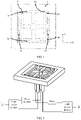
- FIG. 4 is a schematic structural diagram of an antenna according to an embodiment of the present invention.
- a feed signal A and a feed signal B are two polarized signals in dual-polarization.
- Each signal is divided by a 3-db power divider into two equal-amplitude and in-phase signal branches.
- One signal branch of each signal is further subjected to current phase inversion of a 180-degree phase inverter, to obtain two differential and inverse-phase feed branches, which are respectively fed into corresponding ports of an antenna with a 180-degree phase difference.
- the two differential and inverse-phase feed branches, obtained after the processing by the power divider and the phase inverter, of each of the feed signal A and the feed signal B are respectively connected to a low-frequency V-polarization feed radiator (namely, the first radiator 31 and the second radiator 32) and a low-frequency H-polarization feed radiator (namely, the third radiator 33 and the fourth radiator 34) of the antenna by using electric conductors.
- the first coupler 41 and the second coupler 42 are coupled to both the first radiator 31 and the second radiator 32.
- the third coupler 43 and the fourth coupler 44 are coupled to both the third radiator 33 and the fourth radiator 34.
- the first coupler 41 and the second coupler 42 are high-frequency V-polarization
- the first radiator 31 and the second radiator 32 are low-frequency V-polarization
- the third coupler 43 and the fourth coupler 44 are high-frequency H-polarization
- the third radiator 33 and the fourth radiator 34 are low-frequency H-polarization.
- V-polarization and H-polarization are two types of polarization perpendicular to each other, and their polarization directions are defined in the coordinates shown in FIG. 3 .
- a low-frequency V-polarization/H-polarization coupling radiation frame namely, the coupling frame body 2
- a high-frequency V-polarization coupling radiator namely, the first coupler 41 and the second coupler 42
- a high-frequency H-polarization coupling radiator namely, the third coupler 43 and the fourth coupler 44
- the millimeter-wave antenna in the present invention is endowed with features of dual-frequency resonance and dual polarization.
- a step structure is disposed at an opening of the groove.
- a step structure is disposed at an opening of the foregoing groove.
- the step structure may be used for fine tuning of a resonance frequency of the antenna, so that radiation performance of the antenna is higher.
- the plate body is provided with at least two antenna elements, and the at least two antenna elements are arranged along a length direction of the plate body.
- FIG. 5 is a schematic structural diagram of an antenna according to an embodiment of the present invention.
- the antenna is provided with at least two antenna elements.
- the at least two antenna elements are arranged along a length direction of the antenna, which helps form an antenna array.
- the antenna array may be a millimeter-wave antenna array.
- beam forming and beam sweeping may be performed for the antenna array through simultaneous feeding and by adjusting a feed phase difference between sub-antenna elements, thereby improving radiation directivity and gain of the antenna, and improving spatial coverage of radiation.
- a position of each radiator in the antenna element may be adjusted and optimized without changing a general structure of the antenna element, or directions of antenna elements that constitute the array may be collectively adjusted by 90 degrees, and so on.
- openings of grooves of the at least two antenna elements face a same direction.
- openings of grooves of the foregoing at least two antenna elements face a same direction.
- the at least one antenna element is a millimeter-wave antenna element.
- the foregoing at least one antenna element is a millimeter-wave antenna element.
- one surface, away from the groove bottom of the groove, of each of the first radiator, the second radiator, the first coupler, and the second coupler is flush with a plane where an outer side wall of the plate body is located.
- FIG. 1 one surface, away from the groove bottom of the foregoing groove, of each of the foregoing first radiator, second radiator, first coupler, and second coupler is flush with a plane where an outer side wall of the plate body is located.
- the space enclosed by the coupling frame body is a rectangular space.
- the space enclosed by the coupling frame body is a rectangular space.
- each of the four radiators has a T-shaped structure.
- each of the foregoing four radiators has a T-shaped structure.
- An embodiment of the present invention provides an electronic device, including a plate body 1, where the plate body 1 is provided with at least one antenna element, each antenna element includes a groove formed in the plate body 1, a coupling frame body 2 formed in the plate body 1, four radiators 3 formed in the plate body 1, four coupling bodies 4 formed in the plate body 1, and four electric conductors formed in the plate body 1, the four radiators 3 and the four couplers 4 are all disposed in a space enclosed by the coupling frame body 2, the coupling frame body 2 is disposed in the groove, each radiator 3 is provided with a feed point, the different electric conductors penetrate through the groove bottom of the groove and are respectively connected to the feed points on the different radiators, and the four radiators 3 are connected to the four electric conductors in a one-to-one correspondence; the four radiators 3 access two pairs of differential signals; and the plate body 1, the coupling frame body 2, the four radiators 3, and the four couplers 4 are not in contact with one another, an insulating medium 5 is filled between the plate body 1, the coupling
- An embodiment of the present invention further provides an electronic device, including the foregoing antenna, where the electronic device further includes a metal frame, and the plate body of the antenna is a portion of the metal frame.
- the antenna further includes a first antenna, a radiator where at least one antenna element of the antenna is located is a radiator of the first antenna, the radiator is at least a portion of the plate body, and the first antenna is a non-millimeter-wave antenna.
- the foregoing antenna further includes a first antenna, a radiator where at least one antenna element of the antenna is located is a radiator of the first antenna, the radiator is at least a portion of the plate body, and the first antenna is a non-millimeter-wave antenna.
- the at least one antenna element may be disposed on a radiator of a cellular antenna or non-cellular antenna, to share one radiator with the cellular antenna or non-cellular antenna.
Landscapes
- Physics & Mathematics (AREA)
- Electromagnetism (AREA)
- Variable-Direction Aerials And Aerial Arrays (AREA)
- Support Of Aerials (AREA)
Abstract
Description
- This application claims priority to
Chinese Patent Application No. 201911046671.0 filed in China on October 30, 2019 - The present invention relates to the field of communications technologies, and in particular, to an antenna and an electronic device.
- With rapid development of communications technologies, multi-antenna communication has become a mainstream and future development trend of electronic devices. In addition, in this process, millimeter-wave antennas are gradually introduced to the electronic devices. Millimeter-wave antennas can provide a higher communication speed, lower latency, more simultaneous connections, and the like, bringing greater convenience to users' life.
- However, in the prior art, radiation performance of a millimeter-wave antenna is relatively low.
- Embodiments of the present invention provide an antenna and an electronic device, to resolve a problem that radiation performance of a millimeter-wave antenna is relatively low.
- According to a first aspect, an embodiment of the present invention provides an antenna, including a plate body, where the plate body is provided with at least one antenna element, each antenna element includes a groove formed in the plate body, a coupling frame body formed in the plate body, four radiators formed in the plate body, four coupling bodies formed in the plate body, and four electric conductors formed in the plate body, the four radiators and the four couplers are all disposed in a space enclosed by the coupling frame body, the coupling frame body is disposed in the groove, each radiator is provided with a feed point, the different electric conductors penetrate through the groove bottom of the groove and are respectively connected to the feed points on the different radiators, and the four radiators are connected to the four electric conductors in a one-to-one correspondence;
- the four radiators access two pairs of differential signals; and
- the plate body, the coupling frame body, the four radiators, and the four couplers are not in contact with one another, an insulating medium is filled between the plate body, the coupling frame body, the four radiators, and the four couplers, and the four electric conductors are insulated from the groove bottom of the groove.
- According to a second aspect, an embodiment of the present invention provides an electronic device, including the foregoing antenna, where the electronic device further includes a metal frame, and the plate body of the antenna is a portion of the metal frame.
- An antenna provided in the embodiments of the present invention includes a plate body, where the plate body is provided with at least one antenna element, each antenna element includes a groove formed in the plate body, a coupling frame body formed in the plate body, four radiators formed in the plate body, four coupling bodies formed in the plate body, and four electric conductors formed in the plate body, the four radiators and the four couplers are all disposed in a space enclosed by the coupling frame body, the coupling frame body is disposed in the groove, each radiator is provided with a feed point, the different electric conductors penetrate through the groove bottom of the groove and are respectively connected to the feed points on the different radiators, and the four radiators are connected to the four electric conductors in a one-to-one correspondence; the four radiators access two pairs of differential signals; and the plate body, the coupling frame body, the four radiators, and the four couplers are not in contact with one another, an insulating medium is filled between the plate body, the coupling frame body, the four radiators, and the four couplers, and the four electric conductors are insulated from the groove bottom of the groove. The embodiments of the present invention can improve radiation performance of a millimeter-wave antenna.
- To describe the technical solutions in the embodiments of the present invention more clearly, the following briefly describes the accompanying drawings required for describing the embodiments of the present invention. Apparently, the accompanying drawings in the following description show merely some embodiments of the present invention, and a person of ordinary skill in the art may still derive other drawings from these accompanying drawings without creative efforts.
-
FIG. 1 is a first schematic structural diagram of an antenna according to an embodiment of the present invention; -
FIG. 2 is a second schematic structural diagram of an antenna according to an embodiment of the present invention; -
FIG. 3 is a third schematic structural diagram of an antenna according to an embodiment of the present invention; -
FIG. 4 is a fourth schematic structural diagram of an antenna according to an embodiment of the present invention; and -
FIG. 5 is a fifth schematic structural diagram of an antenna according to an embodiment of the present invention. - The following clearly and completely describes the technical solutions in the embodiments of the present invention with reference to the accompanying drawings in the embodiments of the present invention. Apparently, the described embodiments are some but not all of the embodiments of the present invention. All other embodiments obtained by a person of ordinary skill in the art based on the embodiments of the present invention without creative efforts shall fall within the protection scope of the present invention.
-
FIG. 1 to FIG. 3 are all schematic structural diagrams of an antenna according to an embodiment of the present invention. As shown inFIG. 1 to FIG. 3 , the antenna includes aplate body 1, where theplate body 1 is provided with at least one antenna element, and each antenna element includes a groove formed in theplate body 1, acoupling frame body 2 formed in theplate body 1, fourradiators 3 formed in theplate body 1, four coupling bodies 4 formed in theplate body 1, and four electric conductors formed in theplate body 1. The fourradiators 3 and the four couplers 4 are all disposed in a space enclosed by thecoupling frame body 2. Thecoupling frame body 2 is disposed in the groove. Eachradiator 3 is provided with a feed point. The different electric conductors penetrate through the groove bottom of the groove and are respectively connected to the feed points on the different radiators. The fourradiators 3 are connected to the four electric conductors in a one-to-one correspondence. The fourradiators 3 access two pairs of differential signals. Theplate body 1, thecoupling frame body 2, the fourradiators 3, and the four couplers 4 are not in contact with one another, and aninsulating medium 5 is filled between theplate body 1, thecoupling frame body 2, the fourradiators 3, and the four couplers 4. The four electric conductors are insulated from the groove bottom of the groove. - In this embodiment,
FIG. 1 is a schematic structural diagram of an antenna with a groove being filled with aninsulating medium 5, andFIG. 2 is a schematic structural diagram of an antenna with a groove from which aninsulating medium 5 is removed. The foregoing antenna element may be a millimeter-wave antenna element. The foregoing groove may be a rectangular groove. The foregoingcoupling frame body 2 may be a rectangular frame body. Theforegoing radiators 3 may be T-shaped. The foregoing couplers 4 may be strip-shaped. - In this embodiment, the foregoing four
radiators 3 and four couplers 4 may be disposed in layers in the space. For example, tworadiators 3 and two couplers 4 are disposed in a first layer in the space, and the other tworadiators 3 and the other two couplers 4 are disposed in a second layer in the space. - As shown in
FIG. 3 , the fourradiators 3 may include afirst radiator 31, asecond radiator 32, athird radiator 33, and afourth radiator 34. The four couplers 4 may include afirst coupler 41, asecond coupler 42, athird coupler 43, and afourth coupler 44. Thefirst radiator 31, thesecond radiator 32, thefirst coupler 41, and thesecond coupler 42 may be disposed in the first layer in the space. Thethird radiator 33, thefourth radiator 34, thethird coupler 43, and thefourth coupler 44 may be disposed in the second layer in the space. - The four
radiators 3 may radiate low-frequency signals, the four couplers 4 may radiate high-frequency signals, and thecoupling frame body 2 may radiate low-frequency signals. The foregoing four radiators access two pairs of differential signals, which can implement a dual polarization feature. In this way, through reasonable disposing of radiators and couplers in layers, radiators with radiation frequency bands and a polarization characteristic are constructed, so that an antenna element can implement coverage of dual polarization and two resonant frequencies in a limited space, thereby improving radiation performance of a millimeter-wave antenna. In addition, the antenna element may be designed to be disposed on a metal frame. Therefore, in a metal main body design, a millimeter-wave antenna may also be designed to be disposed on the metal main body, to be better designed and integrated with another low-frequency antenna. - In this embodiment, the foregoing electronic device may be a mobile phone, a tablet personal computer (Tablet Personal Computer), a laptop computer (Laptop Computer), a personal digital assistant (personal digital assistant, PDA), a mobile Internet device (Mobile Internet Device, MID), a wearable device (Wearable Device), or the like.
- Optionally, the four
radiators 3 include afirst radiator 31, asecond radiator 32, athird radiator 33, and afourth radiator 34, the four couplers 4 include afirst coupler 41, asecond coupler 42, athird coupler 43, and afourth coupler 44, and the space enclosed by the coupling frame body includes a first space and a second space that are stacked. - The
first radiator 31, thesecond radiator 32, thefirst coupler 41, and thesecond coupler 42 are all disposed in the first space, thefirst radiator 31 and thesecond radiator 32 are symmetrically disposed, thefirst coupler 41 and thesecond coupler 42 are symmetrically disposed, and thefirst radiator 31 and thesecond radiator 32 are both disposed between thefirst coupler 41 and thesecond coupler 42. - The
third radiator 33, thefourth radiator 34, thethird coupler 43, and thefourth coupler 44 are all disposed in the second space, thethird radiator 33 and thefourth radiator 34 are symmetrically disposed, thethird coupler 43 and thefourth coupler 44 are symmetrically disposed, and thethird radiator 33 and thefourth radiator 34 are both disposed between thethird coupler 43 and thefourth coupler 44. - In this implementation, reference may be made to
FIG. 3 to better understand the foregoing structure. As shown inFIG. 3 , the foregoingfirst radiator 31,second radiator 32,first coupler 41, andsecond coupler 42 are all disposed in the foregoing first space, the foregoingfirst radiator 31 andsecond radiator 32 are symmetrically disposed, the foregoingfirst coupler 41 andsecond coupler 42 are symmetrically disposed, and the foregoingfirst radiator 31 andsecond radiator 32 are both disposed between the foregoingfirst coupler 41 andsecond coupler 42. - In this implementation, the foregoing
third radiator 33,fourth radiator 34,third coupler 43, andfourth coupler 44 are all disposed in the second space, the foregoingthird radiator 33 andfourth radiator 34 are symmetrically disposed, the foregoingthird coupler 43 andfourth coupler 44 are symmetrically disposed, and the foregoingthird radiator 33 andfourth radiator 34 are both disposed between the foregoingthird coupler 43 andfourth coupler 44. - It should be noted that, the foregoing first space and second space may be understood as two stacked layers in the space. In this way, through composite construction of a plurality of radiators in each type of polarization, directivity and gain in each type of polarization are improved.
- Optionally, an axis of symmetry between the first radiator and the second radiator is perpendicular to an axis of symmetry between the third radiator and the fourth radiator.
- In this implementation, the axis of symmetry between the foregoing first radiator and second radiator is perpendicular to the axis of symmetry between the foregoing third radiator and fourth radiator, which can make an antenna radiation pattern have higher left-right symmetry.
- Optionally, a feed signal of the first radiator and a feed signal of the second radiator have same magnitude but opposite phase, and a feed signal of the third radiator and a feed signal of the fourth radiator have same magnitude but opposite phase.
- To better understand the foregoing feeding method, reference is made to
FIG. 4 for understanding.FIG. 4 is a schematic structural diagram of an antenna according to an embodiment of the present invention. As shown inFIG. 4 , a feed signal A and a feed signal B are two polarized signals in dual-polarization. Each signal is divided by a 3-db power divider into two equal-amplitude and in-phase signal branches. One signal branch of each signal is further subjected to current phase inversion of a 180-degree phase inverter, to obtain two differential and inverse-phase feed branches, which are respectively fed into corresponding ports of an antenna with a 180-degree phase difference. The two differential and inverse-phase feed branches, obtained after the processing by the power divider and the phase inverter, of each of the feed signal A and the feed signal B are respectively connected to a low-frequency V-polarization feed radiator (namely, thefirst radiator 31 and the second radiator 32) and a low-frequency H-polarization feed radiator (namely, thethird radiator 33 and the fourth radiator 34) of the antenna by using electric conductors. - The
first coupler 41 and thesecond coupler 42 are coupled to both thefirst radiator 31 and thesecond radiator 32. Thethird coupler 43 and thefourth coupler 44 are coupled to both thethird radiator 33 and thefourth radiator 34. Thefirst coupler 41 and thesecond coupler 42 are high-frequency V-polarization, thefirst radiator 31 and thesecond radiator 32 are low-frequency V-polarization, thethird coupler 43 and thefourth coupler 44 are high-frequency H-polarization, and thethird radiator 33 and thefourth radiator 34 are low-frequency H-polarization. - V-polarization and H-polarization are two types of polarization perpendicular to each other, and their polarization directions are defined in the coordinates shown in
FIG. 3 . A low-frequency V-polarization/H-polarization coupling radiation frame (namely, the coupling frame body 2), a high-frequency V-polarization coupling radiator (namely, thefirst coupler 41 and the second coupler 42), and a high-frequency H-polarization coupling radiator (namely, thethird coupler 43 and the fourth coupler 44) generate an electromagnetic induction current through electromagnetic coupling with feed radiators, so that radiation is generated. With such a structure, the millimeter-wave antenna in the present invention is endowed with features of dual-frequency resonance and dual polarization. - In the foregoing feed method, through composite construction of a plurality of radiators in each type of polarization, directivity and gain in each type of polarization are improved. Differential feeding is used, so that an antenna radiation pattern has higher left-right symmetry. Two polarized feed branches are respectively fed into mutually separated feed radiators, so that the antenna has higher polarization purity and port isolation between two types of polarization. The antenna element in the present invention has higher gain. Therefore, array gain can meet requirements of 3GPP even if less array antenna elements are used, which reduces array dimensions compared with an existing design.
- Optionally, a step structure is disposed at an opening of the groove.
- In this implementation, reference may be made to
FIG. 2 for understanding. As shown inFIG. 2 , a step structure is disposed at an opening of the foregoing groove. The step structure may be used for fine tuning of a resonance frequency of the antenna, so that radiation performance of the antenna is higher. - Optionally, the plate body is provided with at least two antenna elements, and the at least two antenna elements are arranged along a length direction of the plate body.
- In this implementation, reference may be made to
FIG. 5 for understanding.FIG. 5 is a schematic structural diagram of an antenna according to an embodiment of the present invention. As shown inFIG. 5 , the antenna is provided with at least two antenna elements. The at least two antenna elements are arranged along a length direction of the antenna, which helps form an antenna array. The antenna array may be a millimeter-wave antenna array. After the antenna array is formed, beam forming and beam sweeping may be performed for the antenna array through simultaneous feeding and by adjusting a feed phase difference between sub-antenna elements, thereby improving radiation directivity and gain of the antenna, and improving spatial coverage of radiation. - Certainly, a position of each radiator in the antenna element may be adjusted and optimized without changing a general structure of the antenna element, or directions of antenna elements that constitute the array may be collectively adjusted by 90 degrees, and so on.
- Optionally, openings of grooves of the at least two antenna elements face a same direction.
- In this implementation, reference may also be made to
FIG. 5 for understanding. As shown inFIG. 5 , openings of grooves of the foregoing at least two antenna elements face a same direction. - Optionally, the at least one antenna element is a millimeter-wave antenna element.
- In this implementation, the foregoing at least one antenna element is a millimeter-wave antenna element.
- Optionally, one surface, away from the groove bottom of the groove, of each of the first radiator, the second radiator, the first coupler, and the second coupler is flush with a plane where an outer side wall of the plate body is located.
- In this implementation, reference may be made to
FIG. 1 for understanding. As shown inFIG. 1 , one surface, away from the groove bottom of the foregoing groove, of each of the foregoing first radiator, second radiator, first coupler, and second coupler is flush with a plane where an outer side wall of the plate body is located. Through such a disposing manner, it can be ensured that the electronic device has a better appearance. - Optionally, the space enclosed by the coupling frame body is a rectangular space.
- In this implementation, the space enclosed by the coupling frame body is a rectangular space.
- Optionally, each of the four radiators has a T-shaped structure.
- In this implementation, each of the foregoing four radiators has a T-shaped structure.
- An embodiment of the present invention provides an electronic device, including a plate body 1, where the plate body 1 is provided with at least one antenna element, each antenna element includes a groove formed in the plate body 1, a coupling frame body 2 formed in the plate body 1, four radiators 3 formed in the plate body 1, four coupling bodies 4 formed in the plate body 1, and four electric conductors formed in the plate body 1, the four radiators 3 and the four couplers 4 are all disposed in a space enclosed by the coupling frame body 2, the coupling frame body 2 is disposed in the groove, each radiator 3 is provided with a feed point, the different electric conductors penetrate through the groove bottom of the groove and are respectively connected to the feed points on the different radiators, and the four radiators 3 are connected to the four electric conductors in a one-to-one correspondence; the four radiators 3 access two pairs of differential signals; and the plate body 1, the coupling frame body 2, the four radiators 3, and the four couplers 4 are not in contact with one another, an insulating medium 5 is filled between the plate body 1, the coupling frame body 2, the four radiators 3, and the four couplers 4, and the four electric conductors are insulated from the groove bottom of the groove. This embodiment of the present invention can improve radiation performance of a millimeter-wave antenna.
- An embodiment of the present invention further provides an electronic device, including the foregoing antenna, where the electronic device further includes a metal frame, and the plate body of the antenna is a portion of the metal frame.
- Optionally, the antenna further includes a first antenna, a radiator where at least one antenna element of the antenna is located is a radiator of the first antenna, the radiator is at least a portion of the plate body, and the first antenna is a non-millimeter-wave antenna.
- In this implementation, the foregoing antenna further includes a first antenna, a radiator where at least one antenna element of the antenna is located is a radiator of the first antenna, the radiator is at least a portion of the plate body, and the first antenna is a non-millimeter-wave antenna. In other words, the at least one antenna element may be disposed on a radiator of a cellular antenna or non-cellular antenna, to share one radiator with the cellular antenna or non-cellular antenna.
- It should be noted that, in this specification, the terms "include", "comprise", or any of their variants are intended to cover a non-exclusive inclusion, so that a process, a method, an article, or an apparatus that includes a series of elements not only includes those elements but also includes other elements that are not expressly listed, or further includes elements inherent to such a process, method, article, or apparatus. An element limited by "includes a ..." does not, without more constraints, preclude the presence of additional identical elements in the process, method, article, or device that includes the element.
- The embodiments of the present invention are described above with reference to the accompanying drawings. However, the present invention is not limited to the foregoing specific implementations. The foregoing specific implementations are merely exemplary, but are not limiting. Under the enlightenment of the present invention, a person of ordinary skill in the art may make many forms without departing from the objective and the scope of the claims of the present invention, and all of which fall within the protection of the present invention.
Claims (13)
- An antenna, characterized by comprising a plate body, wherein the plate body is provided with at least one antenna element, each antenna element comprises a groove formed in the plate body, a coupling frame body formed in the plate body, four radiators formed in the plate body, four coupling bodies formed in the plate body, and four electric conductors formed in the plate body, the four radiators and the four couplers are disposed in a space enclosed by the coupling frame body, the coupling frame body is disposed in the groove, each radiator is provided with a feed point, different electric conductors penetrate through a groove bottom of the groove and are respectively connected to the feed points on different radiators, and the four radiators are connected to the four electric conductors in a one-to-one correspondence;the four radiators access two pairs of differential signals; andthe plate body, the coupling frame body, the four radiators, and the four couplers are not in contact with one another, an insulating medium is filled between the plate body, the coupling frame body, the four radiators, and the four couplers, and the four electric conductors are insulated from the groove bottom of the groove.
- The antenna according to claim 1, characterized in that the four radiators comprise a first radiator, a second radiator, a third radiator, and a fourth radiator, the four couplers comprise a first coupler, a second coupler, a third coupler, and a fourth coupler, and the space enclosed by the coupling frame body comprises a first space and a second space that are stacked;the first radiator, the second radiator, the first coupler, and the second coupler are disposed in the first space, the first radiator and the second radiator are symmetrically disposed, the first coupler and the second coupler are symmetrically disposed, and the first radiator and the second radiator are disposed between the first coupler and the second coupler; andthe third radiator, the fourth radiator, the third coupler, and the fourth coupler are disposed in the second space, the third radiator and the fourth radiator are symmetrically disposed, the third coupler and the fourth coupler are symmetrically disposed, and the third radiator and the fourth radiator are disposed between the third coupler and the fourth coupler.
- The antenna according to claim 2, characterized in that an axis of symmetry between the first radiator and the second radiator is perpendicular to an axis of symmetry between the third radiator and the fourth radiator.
- The antenna according to claim 2, characterized in that a feed signal of the first radiator and a feed signal of the second radiator have same magnitude but opposite phase, and a feed signal of the third radiator and a feed signal of the fourth radiator have same magnitude but opposite phase.
- The antenna according to any one of claims 1 to 4, characterized in that a step structure is disposed at an opening of the groove.
- The antenna according to any one of claims 1 to 4, characterized in that the plate body is provided with at least two antenna elements, and the at least two antenna elements are arranged along a length direction of the plate body.
- The antenna according to claim 6, characterized in that openings of grooves of the at least two antenna elements face a same direction.
- The antenna according to any one of claims 1 to 4, characterized in that the at least one antenna element is a millimeter-wave antenna element.
- The antenna according to any one of claims 2 to 4, characterized in that one surface, facing away from the groove bottom of the groove, of each of the first radiator, the second radiator, the first coupler, and the second coupler is flush with a plane where an outer side wall of the plate body is located.
- The antenna according to claim 1, characterized in that the space enclosed by the coupling frame body is a rectangular space.
- The antenna according to claim 1, characterized in that each of the four radiators is of a T-shaped structure.
- An electronic device, characterized by comprising the antenna according to any one of claims 1 to 11, wherein the electronic device further comprises a metal frame, and the plate body of the antenna is a portion of the metal frame.
- The electronic device according to claim 12, characterized in that the antenna further comprises a first antenna, a radiator where at least one antenna element of the antenna is located is a radiator of the first antenna, the radiator is at least a portion of the plate body, and the first antenna is a non-millimeter-wave antenna.
Applications Claiming Priority (2)
| Application Number | Priority Date | Filing Date | Title |
|---|---|---|---|
| CN201911046671.0A CN110649384B (en) | 2019-10-30 | 2019-10-30 | Antenna and electronic equipment |
| PCT/CN2020/123906 WO2021083123A1 (en) | 2019-10-30 | 2020-10-27 | Antenna and electronic device |
Publications (3)
| Publication Number | Publication Date |
|---|---|
| EP4047745A1 true EP4047745A1 (en) | 2022-08-24 |
| EP4047745A4 EP4047745A4 (en) | 2022-11-23 |
| EP4047745B1 EP4047745B1 (en) | 2026-02-18 |
Family
ID=68995143
Family Applications (1)
| Application Number | Title | Priority Date | Filing Date |
|---|---|---|---|
| EP20881076.2A Active EP4047745B1 (en) | 2019-10-30 | 2020-10-27 | Antenna and electronic device |
Country Status (6)
| Country | Link |
|---|---|
| US (1) | US12074387B2 (en) |
| EP (1) | EP4047745B1 (en) |
| JP (1) | JP7353479B2 (en) |
| KR (1) | KR102666043B1 (en) |
| CN (1) | CN110649384B (en) |
| WO (1) | WO2021083123A1 (en) |
Families Citing this family (2)
| Publication number | Priority date | Publication date | Assignee | Title |
|---|---|---|---|---|
| CN110649384B (en) * | 2019-10-30 | 2021-04-23 | 维沃移动通信有限公司 | Antenna and electronic equipment |
| CN113571898B (en) * | 2021-07-27 | 2024-06-07 | 维沃移动通信有限公司 | Electronic equipment |
Family Cites Families (15)
| Publication number | Priority date | Publication date | Assignee | Title |
|---|---|---|---|---|
| JP2009225030A (en) * | 2008-03-14 | 2009-10-01 | Toshiba Corp | Planar antenna |
| CN104916910B (en) * | 2015-06-12 | 2018-06-22 | 华南理工大学 | Dual-polarized base station antenna based on coupling feed structure |
| EP3168927B1 (en) * | 2015-11-16 | 2022-02-23 | Huawei Technologies Co., Ltd. | Ultra compact ultra broad band dual polarized base station antenna |
| CN106602242B (en) * | 2016-11-25 | 2019-04-09 | 电子科技大学 | A Low Profile High Gain Dual Polarized Antenna |
| US11336015B2 (en) * | 2018-03-28 | 2022-05-17 | Intel Corporation | Antenna boards and communication devices |
| CN109346829B (en) * | 2018-09-28 | 2020-10-02 | 维沃移动通信有限公司 | Terminal equipment |
| CN109713440A (en) * | 2018-12-28 | 2019-05-03 | 瑞声精密制造科技(常州)有限公司 | A kind of antenna element and array antenna |
| CN109742533B (en) * | 2019-02-18 | 2023-11-03 | 华南理工大学 | A differentially fed dual-polarization pattern reconfigurable antenna |
| CN110098465B (en) * | 2019-04-26 | 2021-10-29 | 维沃移动通信有限公司 | A wireless terminal device with a highly integrated antenna design |
| CN110212283B (en) * | 2019-05-22 | 2021-06-08 | 维沃移动通信有限公司 | An antenna unit and terminal equipment |
| US11387557B2 (en) * | 2019-07-10 | 2022-07-12 | Mediatek Inc. | Antenna for multi-broadband and multi-polarization communication |
| CN110649384B (en) * | 2019-10-30 | 2021-04-23 | 维沃移动通信有限公司 | Antenna and electronic equipment |
| US11411321B2 (en) * | 2019-12-05 | 2022-08-09 | Qualcomm Incorporated | Broadband antenna system |
| KR102695146B1 (en) * | 2020-04-02 | 2024-08-13 | 삼성전기주식회사 | Chip antenna |
| CN112909506B (en) * | 2021-01-16 | 2021-10-12 | 深圳市睿德通讯科技有限公司 | Antenna structure and antenna array |
-
2019
- 2019-10-30 CN CN201911046671.0A patent/CN110649384B/en active Active
-
2020
- 2020-10-27 WO PCT/CN2020/123906 patent/WO2021083123A1/en not_active Ceased
- 2020-10-27 EP EP20881076.2A patent/EP4047745B1/en active Active
- 2020-10-27 KR KR1020227016034A patent/KR102666043B1/en active Active
- 2020-10-27 JP JP2022523546A patent/JP7353479B2/en active Active
-
2022
- 2022-04-22 US US17/727,688 patent/US12074387B2/en active Active
Also Published As
| Publication number | Publication date |
|---|---|
| CN110649384B (en) | 2021-04-23 |
| JP7353479B2 (en) | 2023-09-29 |
| WO2021083123A1 (en) | 2021-05-06 |
| CN110649384A (en) | 2020-01-03 |
| JP2022553053A (en) | 2022-12-21 |
| KR20220071980A (en) | 2022-05-31 |
| US20220247079A1 (en) | 2022-08-04 |
| KR102666043B1 (en) | 2024-05-16 |
| EP4047745A4 (en) | 2022-11-23 |
| EP4047745B1 (en) | 2026-02-18 |
| US12074387B2 (en) | 2024-08-27 |
Similar Documents
| Publication | Publication Date | Title |
|---|---|---|
| US11387568B2 (en) | Millimeter-wave antenna array element, array antenna, and communications product | |
| CN108886202B (en) | Wireless communication system including variable polarization phased array antenna | |
| Xia et al. | Millimeter-wave phased array antenna integrated with the industry design in 5G/B5G smartphones | |
| KR102614892B1 (en) | Antenna units and terminal equipment | |
| KR102641158B1 (en) | Dual-band Dual-polarized antenna radiation device | |
| CN111129704B (en) | An antenna unit and electronic equipment | |
| US10044111B2 (en) | Wideband dual-polarized patch antenna | |
| EP4007067B1 (en) | Antenna unit and electronic device | |
| US9184507B2 (en) | Multi-slot common aperture dual polarized omni-directional antenna | |
| WO2022002139A1 (en) | Electronic device | |
| CN110148828B (en) | Antenna unit and electronic device | |
| EP3852194B1 (en) | Terminal device antenna | |
| CN106602242A (en) | Low-profile high-gain dual-polarized antenna | |
| WO2019039004A1 (en) | Leaky wave antenna | |
| US12327928B1 (en) | Multi-frequency base station antenna unit and communication device | |
| EP3975336A1 (en) | Antenna unit and electronic device | |
| CN110911814A (en) | An antenna unit and electronic equipment | |
| US12074387B2 (en) | Antenna and electronic device | |
| US6473040B1 (en) | Patch antenna array with isolated elements | |
| CN117913546B (en) | Broadband/high-isolation/low-cross-polarization dual-polarized antenna array | |
| CN111162379B (en) | Polarization adjustable antenna array based on double-layer patch antenna | |
| CN120530534A (en) | Antennas, antenna devices and antenna equipment | |
| JPH05191132A (en) | Plane antenna | |
| CN120728245A (en) | Microstrip patch antenna, UWB antenna and vehicle | |
| JPH10510110A (en) | Receiving module for extremely high frequency directional electromagnetic field reception |
Legal Events
| Date | Code | Title | Description |
|---|---|---|---|
| STAA | Information on the status of an ep patent application or granted ep patent |
Free format text: STATUS: THE INTERNATIONAL PUBLICATION HAS BEEN MADE |
|
| PUAI | Public reference made under article 153(3) epc to a published international application that has entered the european phase |
Free format text: ORIGINAL CODE: 0009012 |
|
| STAA | Information on the status of an ep patent application or granted ep patent |
Free format text: STATUS: REQUEST FOR EXAMINATION WAS MADE |
|
| 17P | Request for examination filed |
Effective date: 20220516 |
|
| AK | Designated contracting states |
Kind code of ref document: A1 Designated state(s): AL AT BE BG CH CY CZ DE DK EE ES FI FR GB GR HR HU IE IS IT LI LT LU LV MC MK MT NL NO PL PT RO RS SE SI SK SM TR |
|
| A4 | Supplementary search report drawn up and despatched |
Effective date: 20221024 |
|
| RIC1 | Information provided on ipc code assigned before grant |
Ipc: H01Q 5/40 20150101ALN20221018BHEP Ipc: H01Q 21/24 20060101AFI20221018BHEP |
|
| DAV | Request for validation of the european patent (deleted) | ||
| DAX | Request for extension of the european patent (deleted) | ||
| REG | Reference to a national code |
Ref country code: DE Ref legal event code: R079 Free format text: PREVIOUS MAIN CLASS: H01Q0001380000 Ipc: H01Q0021240000 Ref document number: 602020067266 Country of ref document: DE |
|
| GRAP | Despatch of communication of intention to grant a patent |
Free format text: ORIGINAL CODE: EPIDOSNIGR1 |
|
| STAA | Information on the status of an ep patent application or granted ep patent |
Free format text: STATUS: GRANT OF PATENT IS INTENDED |
|
| RIC1 | Information provided on ipc code assigned before grant |
Ipc: H01Q 21/24 20060101AFI20251121BHEP Ipc: H01Q 5/40 20150101ALI20251121BHEP |
|
| INTG | Intention to grant announced |
Effective date: 20251209 |
|
| GRAS | Grant fee paid |
Free format text: ORIGINAL CODE: EPIDOSNIGR3 |
|
| GRAA | (expected) grant |
Free format text: ORIGINAL CODE: 0009210 |
|
| STAA | Information on the status of an ep patent application or granted ep patent |
Free format text: STATUS: THE PATENT HAS BEEN GRANTED |
|
| AK | Designated contracting states |
Kind code of ref document: B1 Designated state(s): AL AT BE BG CH CY CZ DE DK EE ES FI FR GB GR HR HU IE IS IT LI LT LU LV MC MK MT NL NO PL PT RO RS SE SI SK SM TR |
|
| REG | Reference to a national code |
Ref country code: CH Ref legal event code: F10 Free format text: ST27 STATUS EVENT CODE: U-0-0-F10-F00 (AS PROVIDED BY THE NATIONAL OFFICE) Effective date: 20260218 Ref country code: GB Ref legal event code: FG4D |
|
| REG | Reference to a national code |
Ref country code: IE Ref legal event code: FG4D |
|
| REG | Reference to a national code |
Ref country code: DE Ref legal event code: R096 Ref document number: 602020067266 Country of ref document: DE |
|
| REG | Reference to a national code |
Ref country code: NL Ref legal event code: MP Effective date: 20260218 |
|
| PG25 | Lapsed in a contracting state [announced via postgrant information from national office to epo] |
Ref country code: RS Free format text: LAPSE BECAUSE OF FAILURE TO SUBMIT A TRANSLATION OF THE DESCRIPTION OR TO PAY THE FEE WITHIN THE PRESCRIBED TIME-LIMIT Effective date: 20260518 |
|
| PG25 | Lapsed in a contracting state [announced via postgrant information from national office to epo] |
Ref country code: ES Free format text: LAPSE BECAUSE OF FAILURE TO SUBMIT A TRANSLATION OF THE DESCRIPTION OR TO PAY THE FEE WITHIN THE PRESCRIBED TIME-LIMIT Effective date: 20260218 |
|
| PG25 | Lapsed in a contracting state [announced via postgrant information from national office to epo] |
Ref country code: PL Free format text: LAPSE BECAUSE OF FAILURE TO SUBMIT A TRANSLATION OF THE DESCRIPTION OR TO PAY THE FEE WITHIN THE PRESCRIBED TIME-LIMIT Effective date: 20260218 |
|
| PG25 | Lapsed in a contracting state [announced via postgrant information from national office to epo] |
Ref country code: GR Free format text: LAPSE BECAUSE OF FAILURE TO SUBMIT A TRANSLATION OF THE DESCRIPTION OR TO PAY THE FEE WITHIN THE PRESCRIBED TIME-LIMIT Effective date: 20260519 |
|
| REG | Reference to a national code |
Ref country code: LT Ref legal event code: MG9D |
|
| PG25 | Lapsed in a contracting state [announced via postgrant information from national office to epo] |
Ref country code: LT Free format text: LAPSE BECAUSE OF FAILURE TO SUBMIT A TRANSLATION OF THE DESCRIPTION OR TO PAY THE FEE WITHIN THE PRESCRIBED TIME-LIMIT Effective date: 20260218 |
|
| PG25 | Lapsed in a contracting state [announced via postgrant information from national office to epo] |
Ref country code: NO Free format text: LAPSE BECAUSE OF FAILURE TO SUBMIT A TRANSLATION OF THE DESCRIPTION OR TO PAY THE FEE WITHIN THE PRESCRIBED TIME-LIMIT Effective date: 20260518 |
|
| PG25 | Lapsed in a contracting state [announced via postgrant information from national office to epo] |
Ref country code: FI Free format text: LAPSE BECAUSE OF FAILURE TO SUBMIT A TRANSLATION OF THE DESCRIPTION OR TO PAY THE FEE WITHIN THE PRESCRIBED TIME-LIMIT Effective date: 20260218 Ref country code: AT Free format text: LAPSE BECAUSE OF FAILURE TO SUBMIT A TRANSLATION OF THE DESCRIPTION OR TO PAY THE FEE WITHIN THE PRESCRIBED TIME-LIMIT Effective date: 20260218 Ref country code: SE Free format text: LAPSE BECAUSE OF FAILURE TO SUBMIT A TRANSLATION OF THE DESCRIPTION OR TO PAY THE FEE WITHIN THE PRESCRIBED TIME-LIMIT Effective date: 20260218 |
|
| REG | Reference to a national code |
Ref country code: AT Ref legal event code: MK05 Ref document number: 1889242 Country of ref document: AT Kind code of ref document: T Effective date: 20260218 |
|
| PG25 | Lapsed in a contracting state [announced via postgrant information from national office to epo] |
Ref country code: HR Free format text: LAPSE BECAUSE OF FAILURE TO SUBMIT A TRANSLATION OF THE DESCRIPTION OR TO PAY THE FEE WITHIN THE PRESCRIBED TIME-LIMIT Effective date: 20260218 |
|
| PG25 | Lapsed in a contracting state [announced via postgrant information from national office to epo] |
Ref country code: PT Free format text: LAPSE BECAUSE OF FAILURE TO SUBMIT A TRANSLATION OF THE DESCRIPTION OR TO PAY THE FEE WITHIN THE PRESCRIBED TIME-LIMIT Effective date: 20260618 Ref country code: IS Free format text: LAPSE BECAUSE OF FAILURE TO SUBMIT A TRANSLATION OF THE DESCRIPTION OR TO PAY THE FEE WITHIN THE PRESCRIBED TIME-LIMIT Effective date: 20260618 |
|
| PG25 | Lapsed in a contracting state [announced via postgrant information from national office to epo] |
Ref country code: NL Free format text: LAPSE BECAUSE OF FAILURE TO SUBMIT A TRANSLATION OF THE DESCRIPTION OR TO PAY THE FEE WITHIN THE PRESCRIBED TIME-LIMIT Effective date: 20260218 |
|
| PG25 | Lapsed in a contracting state [announced via postgrant information from national office to epo] |
Ref country code: LV Free format text: LAPSE BECAUSE OF FAILURE TO SUBMIT A TRANSLATION OF THE DESCRIPTION OR TO PAY THE FEE WITHIN THE PRESCRIBED TIME-LIMIT Effective date: 20260218 |
|
| PG25 | Lapsed in a contracting state [announced via postgrant information from national office to epo] |
Ref country code: BG Free format text: LAPSE BECAUSE OF FAILURE TO SUBMIT A TRANSLATION OF THE DESCRIPTION OR TO PAY THE FEE WITHIN THE PRESCRIBED TIME-LIMIT Effective date: 20260218 |