EP4047727A1 - Battery pack case comprising hook coupling structure - Google Patents
Battery pack case comprising hook coupling structure Download PDFInfo
- Publication number
- EP4047727A1 EP4047727A1 EP22168629.8A EP22168629A EP4047727A1 EP 4047727 A1 EP4047727 A1 EP 4047727A1 EP 22168629 A EP22168629 A EP 22168629A EP 4047727 A1 EP4047727 A1 EP 4047727A1
- Authority
- EP
- European Patent Office
- Prior art keywords
- hook
- battery pack
- hook part
- locking projection
- case
- Prior art date
- Legal status (The legal status is an assumption and is not a legal conclusion. Google has not performed a legal analysis and makes no representation as to the accuracy of the status listed.)
- Granted
Links
Images




Classifications
-
- H—ELECTRICITY
- H01—ELECTRIC ELEMENTS
- H01M—PROCESSES OR MEANS, e.g. BATTERIES, FOR THE DIRECT CONVERSION OF CHEMICAL ENERGY INTO ELECTRICAL ENERGY
- H01M50/00—Constructional details or processes of manufacture of the non-active parts of electrochemical cells other than fuel cells, e.g. hybrid cells
- H01M50/20—Mountings; Secondary casings or frames; Racks, modules or packs; Suspension devices; Shock absorbers; Transport or carrying devices; Holders
- H01M50/233—Mountings; Secondary casings or frames; Racks, modules or packs; Suspension devices; Shock absorbers; Transport or carrying devices; Holders characterised by physical properties of casings or racks, e.g. dimensions
- H01M50/242—Mountings; Secondary casings or frames; Racks, modules or packs; Suspension devices; Shock absorbers; Transport or carrying devices; Holders characterised by physical properties of casings or racks, e.g. dimensions adapted for protecting batteries against vibrations, collision impact or swelling
-
- H—ELECTRICITY
- H01—ELECTRIC ELEMENTS
- H01M—PROCESSES OR MEANS, e.g. BATTERIES, FOR THE DIRECT CONVERSION OF CHEMICAL ENERGY INTO ELECTRICAL ENERGY
- H01M50/00—Constructional details or processes of manufacture of the non-active parts of electrochemical cells other than fuel cells, e.g. hybrid cells
- H01M50/20—Mountings; Secondary casings or frames; Racks, modules or packs; Suspension devices; Shock absorbers; Transport or carrying devices; Holders
- H01M50/262—Mountings; Secondary casings or frames; Racks, modules or packs; Suspension devices; Shock absorbers; Transport or carrying devices; Holders with fastening means, e.g. locks
- H01M50/264—Mountings; Secondary casings or frames; Racks, modules or packs; Suspension devices; Shock absorbers; Transport or carrying devices; Holders with fastening means, e.g. locks for cells or batteries, e.g. straps, tie rods or peripheral frames
-
- B—PERFORMING OPERATIONS; TRANSPORTING
- B65—CONVEYING; PACKING; STORING; HANDLING THIN OR FILAMENTARY MATERIAL
- B65D—CONTAINERS FOR STORAGE OR TRANSPORT OF ARTICLES OR MATERIALS, e.g. BAGS, BARRELS, BOTTLES, BOXES, CANS, CARTONS, CRATES, DRUMS, JARS, TANKS, HOPPERS, FORWARDING CONTAINERS; ACCESSORIES, CLOSURES, OR FITTINGS THEREFOR; PACKAGING ELEMENTS; PACKAGES
- B65D45/00—Clamping or other pressure-applying devices for securing or retaining closure members
- B65D45/02—Clamping or other pressure-applying devices for securing or retaining closure members for applying axial pressure to engage closure with sealing surface
- B65D45/16—Clips, hooks, or clamps which are removable, or which remain connected either with the closure or with the container when the container is open, e.g. C-shaped
-
- H—ELECTRICITY
- H01—ELECTRIC ELEMENTS
- H01M—PROCESSES OR MEANS, e.g. BATTERIES, FOR THE DIRECT CONVERSION OF CHEMICAL ENERGY INTO ELECTRICAL ENERGY
- H01M50/00—Constructional details or processes of manufacture of the non-active parts of electrochemical cells other than fuel cells, e.g. hybrid cells
- H01M50/20—Mountings; Secondary casings or frames; Racks, modules or packs; Suspension devices; Shock absorbers; Transport or carrying devices; Holders
- H01M50/258—Modular batteries; Casings provided with means for assembling
-
- H—ELECTRICITY
- H01—ELECTRIC ELEMENTS
- H01M—PROCESSES OR MEANS, e.g. BATTERIES, FOR THE DIRECT CONVERSION OF CHEMICAL ENERGY INTO ELECTRICAL ENERGY
- H01M50/00—Constructional details or processes of manufacture of the non-active parts of electrochemical cells other than fuel cells, e.g. hybrid cells
- H01M50/20—Mountings; Secondary casings or frames; Racks, modules or packs; Suspension devices; Shock absorbers; Transport or carrying devices; Holders
- H01M50/262—Mountings; Secondary casings or frames; Racks, modules or packs; Suspension devices; Shock absorbers; Transport or carrying devices; Holders with fastening means, e.g. locks
-
- Y—GENERAL TAGGING OF NEW TECHNOLOGICAL DEVELOPMENTS; GENERAL TAGGING OF CROSS-SECTIONAL TECHNOLOGIES SPANNING OVER SEVERAL SECTIONS OF THE IPC; TECHNICAL SUBJECTS COVERED BY FORMER USPC CROSS-REFERENCE ART COLLECTIONS [XRACs] AND DIGESTS
- Y02—TECHNOLOGIES OR APPLICATIONS FOR MITIGATION OR ADAPTATION AGAINST CLIMATE CHANGE
- Y02E—REDUCTION OF GREENHOUSE GAS [GHG] EMISSIONS, RELATED TO ENERGY GENERATION, TRANSMISSION OR DISTRIBUTION
- Y02E60/00—Enabling technologies; Technologies with a potential or indirect contribution to GHG emissions mitigation
- Y02E60/10—Energy storage using batteries
Definitions
- the hook coupling structure typically provided in accordance with the related art includes a first structure 10 that is formed by injection molding and disposed as a lower component and a second structure 20 that is disposed above the first structure 10 and has a shape corresponding to the first structure 10.
- a locking projection 31 protrudes outward from a predetermined area inside a side wall part, and a support 32 extends upward from the first structure 30 and is spaced a predetermined interval from the locking projection 31.
- a device includes the battery pack case.
- the bent portion of the hook part may have a thickness greater than that of an extension portion of the hook part.
- the battery pack lower case may include: a through-hole 730 formed by punching a predetermined area on the bottom surface of the battery pack lower case so that a predetermined area of the bent portion of the battery pack upper case is disposed to the inside; and a locking projection 740 positioned, while spaced a predetermined height from the through-hole, in a predetermined area that is on a side surface of the battery pack lower case and corresponds to the hook part of the battery pack upper case, wherein the bent portion of the battery pack upper case is locked in the locking projection.
- the first bent surface 111_1 When the thickness of the first bent surface 111_1 is less than that of the upper surface of the protrusion part 121, the end portion of the hook part 111 may not be sufficiently locked in the protrusion part 121. Also, when the thickness of the first bent surface 111_1 is excessively greater by the predetermined range than that of the upper surface of the protrusion part 121, a tight coupling is not established due to a gap between the end portion of the hook part 111 and the protrusion part 121 after the hook coupling. Thus, the first bent surface is provided having an appropriately large thickness.
- the first bent surface 211 is a surface formed by bending once the edge of the upper case 200.
- the first bent surface 211 has a thickness equal to or greater by a predetermined range than that of an upper surface of the protrusion part 320.
Landscapes
- Chemical & Material Sciences (AREA)
- Chemical Kinetics & Catalysis (AREA)
- Electrochemistry (AREA)
- General Chemical & Material Sciences (AREA)
- Engineering & Computer Science (AREA)
- Mechanical Engineering (AREA)
- Battery Mounting, Suspending (AREA)
- Rigid Containers With Two Or More Constituent Elements (AREA)
- Connection Of Plates (AREA)
Abstract
Description
- The present invention relates to a hook coupling structure and a battery pack case using same, and more particularly, to a hook coupling structure in which a structure body having the hook structure body provided therein is utilized, and a battery pack case using the same.
- Various means are used to couple injection-molded products to each other. For example, components are coupled to each other by using screws, or components are coupled to each other by using hooks and locking protrusions that are integrated with the component themselves.
-
FIG. 1 is a side view of a hook coupling structure in accordance with the related art. - Referring to
FIG. 1 , the hook coupling structure typically provided in accordance with the related art includes afirst structure 10 that is formed by injection molding and disposed as a lower component and asecond structure 20 that is disposed above thefirst structure 10 and has a shape corresponding to thefirst structure 10. - The
first structure 10 includes alocking projection 11 that protrudes outward from a predetermined area inside a side wall part, and thesecond structure 20 includes ahook part 21 that includes a body 21_1 and a protrusion part 21_2. The body is disposed at a position corresponding to thelocking projection 11 and extends downward from thesecond structure 20, and the protrusion part extends from the body 21_1 and protrudes toward thelocking projection 11. - Generally, the
hook part 21 is elastically deformable by a predetermined amount. When thelocking projection 11 of thefirst structure 10 and the protrusion part 21_2 of thesecond structure 20 are coupled to each other, the protrusion part 21_2 is locked in thelocking projection 11 to couple thefirst structure 10 and thesecond structure 20, while thehook part 21 is moved back by thelocking projection 11, elastically deformed by a certain amount, then recovered. - However, in the hook coupling structure in accordance with the related art, the
hook part 21 is moved back and separated from thelocking projection 11 when the entire structure is impacted after thefirst structure 10 and thesecond structure 20 are coupled to each other. As a result, thefirst structure 10 and thesecond structure 20 may be disconnected. - To solve the above-described problem, a structure for supporting the hook part is necessary. This will be described in detail in
FIG. 2 . -
FIG. 2 is a side view of another hook coupling structure obtained by improving the hook coupling structure in accordance with the related art. - Referring to
FIG. 2 , another hook coupling structure includes afirst structure 30 that is disposed as a lower component and asecond structure 40 that is disposed above thefirst structure 30 and has a shape corresponding to thefirst structure 30. When applied to a battery pack, the first structure may serve as a lower case, and the second structure may serve as an upper case. - In the
first structure 30, alocking projection 31 protrudes outward from a predetermined area inside a side wall part, and asupport 32 extends upward from thefirst structure 30 and is spaced a predetermined interval from thelocking projection 31. - In the
second structure 40, ahook part 41 includes a body 41_1 that is disposed between thelocking projection 31 and thesupport 32 and extends downward from thesecond structure 40 and a protrusion part 41_2 that extends from the body 41_1 and protrudes toward thelocking projection 31. - The
hook part 41 and thesupport 32 may be elastically deformed by a predetermined amount, and when thefirst structure 30 and thesecond structure 40 are coupled to each other, thehook part 41 is inserted between thelocking projection 31 and thesupport 32. Accordingly, when thehook part 41 is inserted, the protrusion part 41_2 is locked in thelocking projection 31 to couple thefirst structure 30 and thesecond structure 40, while thehook part 41 and thesupport 32 are elastically deformed by a certain amount and then recovered. - As the above-described structure includes the
support 32 unlike the hook coupling structure in accordance with the related art, thefirst structure 30 and thesecond structure 40 may not be disconnected from each other even when the entire structure is impacted after thefirst structure 30 and thesecond structure 40 are coupled to each other. - Recently, reduction in sizes of diverse structure bodies has been a main issue to satisfy various demands of customers. However, since the support 22 is additionally required in the related art, a structure of the hook coupling structure may be complicated, and a space utilization rate may be deteriorated.
- Thus, the development of technology for a hook coupling structure having an increased space utilization rate has been required.
-
-
JP1996-028209B -
JP6301893B - The present invention provides a hook coupling structure for reducing a size of a structure body and a battery pack case using the same.
- In accordance with an exemplary embodiment, a hook coupling structure includes: an
upper structure body 110 including ahook part 111 that extends downward from an edge and has an end portion bent to the inside; and alower structure body 120 including aprotrusion part 121 and coupled to the upper structure body, the protrusion part being lifted upward from an edge and disposed inside thehook part 111, wherein the lower structure body includes alocking projection 130 that is formed, at a position corresponding to an upper portion of thehook part 111 of theupper structure body 110, by protruding an inner surface of the lower structure body outward. - Also, the
hook part 111 is inserted between thelocking projection 130 and theprotrusion part 121 to establish a coupling. - The hook part may have: a first bent surface 111_1 that is a surface formed through bending and is in contact with the
protrusion part 121 of the lower structure body; and a second bent surface 111_2 that is a surface formed through bending and is in contact with thelocking projection 130. - The first bent surface of the hook part may have a thickness greater than or equal to that of the protrusion part.
- The second bent surface of the hook part may have a thickness less than that of the locking projection.
- An insertion-coupling ridge 140 may be defined between the locking projection and the protrusion part of the lower structure body so that a bent portion of the hook part is positioned therein.
- In accordance with an exemplary embodiment, a battery pack case includes: a battery pack
lower case 300 having an insertion-coupling ridge defined in a predetermined area of an edge; and a battery packupper case 200 including ahook part 210 that has an end portion bent at a position corresponding to the insertion-coupling ridge of the battery pack lower case, wherein the insertion-coupling ridge of the lower case and the hook part of the upper case are coupled to each other to establish a hook coupling structure. - The battery pack lower case may include: a
locking projection 310 positioned at a height to be in contact with an upper surface of the hook part and disposed on a plane adjacent to a plane in which the hook part is disposed, the locking projection protruding outward so that the hook part of the battery pack upper case is locked therein; and aprotrusion part 320 positioned at a height to be in contact with a lower surface of the hook part and disposed on a plane identical to a plane in which the hook part is disposed, the protrusion part being lifted upward to support the hook part. - The hook part of the battery pack upper case may have: a
first bent surface 211 that is a surface formed through bending and is in contact with theprotrusion part 320 of the lower structure body; and asecond bent surface 212 that is a surface formed through bending and is in contact with thelocking projection 310. - An insertion-
coupling ridge 330 may be defined between the locking projection and the protrusion part of the battery pack lower case so that the hook part is positioned therein. - In accordance with an exemplary embodiment, a device includes the battery pack case.
- In accordance with another exemplary embodiment, a hook coupling structure includes: an
upper structure body 510 including ahook part 511 that extends from an upper surface and has a protruding end portion; and alower structure body 520 including a through-hole 530 and alocking projection 540, the through-hole formed by punching a predetermined area of a bottom surface so that a predetermined area of the hook part is disposed inside the bottom surface, the locking projection being formed, at a position corresponding to an upper portion of thehook part 511 of theupper structure body 510, by protruding an inner surface of the lower structure body outward. - Also, the predetermined area of the hook part is inserted into the through-hole to establish a coupling.
- The bottom surface may include: a
first bottom part 521 positioned on one side of the through-hole; and asecond bottom part 522 positioned on the other side of the through-hole. - Among the first bottom part and the second bottom part, the bottom part in an area, in which the locking projection is not positioned, may support a predetermined area on a non-protruding side of the hook part.
- An insertion-
coupling ridge 550 may be defined between the locking projection of the lower structure and the through-hole so that a bent portion of the hook part is positioned to the inside thereof. - The bent portion of the hook part may have a thickness greater than that of an extension portion of the hook part.
- The through-hole may have a size greater than or equal to the thickness of the bent portion.
- In accordance with another exemplary embodiment, a battery pack case includes: a battery pack
lower case 700 having an insertion-coupling ridge defined in a predetermined area on a bottom surface; and a battery packupper case 600 including ahook part 610 with abent portion 611 in which an end portion protrudes at a position corresponding to the insertion-coupling ridge of the battery pack lower case. - The insertion-coupling ridge of the lower case and the hook part of the upper case are coupled to each other to establish a hook coupling structure.
- The battery pack lower case may include: a through-
hole 730 formed by punching a predetermined area on the bottom surface of the battery pack lower case so that a predetermined area of the bent portion of the battery pack upper case is disposed to the inside; and alocking projection 740 positioned, while spaced a predetermined height from the through-hole, in a predetermined area that is on a side surface of the battery pack lower case and corresponds to the hook part of the battery pack upper case, wherein the bent portion of the battery pack upper case is locked in the locking projection. - The battery pack lower case may further include: a
side wall part 710 positioned on one side of the through-hole; and abottom part 720 positioned on the other side of the through-hole. - The bottom part may support a predetermined area on a non-protruding side of the bent portion of the hook part.
- The insertion-
coupling ridge 750 may be defined between the locking projection and the bottom surface so that the bent portion of the hook part is positioned between the locking projection and the through-hole of the bottom surface. - In accordance with another exemplary embodiment, a device includes the battery pack case.
- In the hook coupling structure in accordance with the embodiments of the present invention and the battery pack case using the same, a structure body is used instead of the support in accordance with the related art which is separately disposed to prevent the hook from being moved back, and thus the support may be removed to increase the space utilization rate.
-
-
FIG. 1 is a side view of a hook coupling structure in accordance with the related art. -
FIG. 2 is a side view of another hook coupling structure obtained by improving the hook coupling structure in accordance with the related art. -
FIG. 3 is a side view of a hook coupling structure in accordance with an embodiment of the present invention. -
FIG. 4 is an enlarged side view of a hook part in accordance with the embodiment of the present invention. -
FIG. 5 is a side view of the hook coupling structure before a hook part in accordance with the embodiment of the present invention is inserted. -
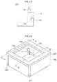
FIG. 6 is a view of an inner structure of a battery pack case in accordance with an embodiment of the present invention. - (a) of
FIG. 7 is a cross-sectional view taken along line A-A' in an area with a hook coupling structure within the battery pack case in accordance with the embodiment of the present invention. - (b) of
FIG. 7 is a cross-sectional view taken along line B-B' in an area without a hook coupling structure within the battery pack case in accordance with the embodiment of the present invention. -
FIG. 8 is a side view of the hook coupling structure in the battery pack case in accordance with the embodiment of the present invention. -
FIG. 9 is a side view of the hook coupling structure before a hook part in the battery pack case in accordance with the embodiment of the present invention is inserted. -
FIG. 10 is an enlarged side view of the hook part in the battery pack case in accordance with the embodiment of the present invention. -
FIG. 11 is a side view of a hook coupling structure in accordance with another embodiment of the present invention. -
FIG. 12 is a side view of the hook coupling structure before a hook part in accordance with another embodiment of the present invention is inserted. -
FIG. 13 is a view of an inner structure of a battery pack case in accordance with another embodiment of the present invention. -
FIG. 14 is a cut side view of a hook coupling structure in the battery pack case in accordance with another embodiment of the present invention. -
FIG. 15 is a cut side view of the hook coupling structure in the battery pack case before a hook part in accordance with another embodiment of the present invention is inserted. - Hereinafter, embodiments of the present invention will be described in detail with reference to the illustrations in the accompanying drawings. However, the present invention is not limited or restricted to the embodiments. Rather, these embodiments are provided so that this disclosure will be thorough and complete, and will fully convey the scope of the present invention to those skilled in the art.
- Although the ordinal numbers such as first and second are used herein to describe various elements, these elements should not be limited by these numbers. The terms are only used to distinguish one component from other components. For example, a first element can be referred to as a second element, and similarly a second element can be referred to as a first element without departing from the scope of the present invention. The terms herein are used only for explaining a specific embodiment while not intended to limit the present invention. The expression of a singular form includes plural forms unless definitely indicating a particular case in terms of the context.
- The terms used in the present invention are selected as general terms currently and widely used in consideration of functions of the present invention, but the terms may vary in accordance with the intention of those skilled in the art, precedents, or new technology in the art. Also, specific terms may be temporarily selected by the applicant, and in this case, the detailed meaning thereof will be described in the detailed description of the invention. Thus, the terms used in the present invention should be defined not as simple terms but based on the meaning of the terms and the overall description of the invention.
- Next, a hook coupling structure in accordance with an embodiment of the present invention will be described.
- In the hook coupling structure in accordance with the embodiment of the present invention, a protrusion is formed by lifting an edge of a lower structure body in which the hook coupling structure is provided, and a hook part is supported by the protrusion so that the hook part is not moved back after locked in a locking projection. Therefore, a space utilization rate of the hook coupling structure may increase.
-
FIG. 3 is a side view of the hook coupling structure in accordance with the embodiment of the present invention. - Referring to
FIG. 3 , ahook coupling structure 100 in accordance with the embodiment of the present invention includes anupper structure body 110 that includes ahook part 111 that extends downward from an edge and has an end portion bent to the inside, alower structure body 120 that includes aprotrusion part 121 lifted upward from an edge and disposed inside thehook part 111, and a lockingprojection 130 in which thehook part 111 of theupper structure body 110 is locked. - Also, the hook part is inserted between the locking
projection 130 and theprotrusion part 121 to establish a coupling. - A configuration of the hook coupling structure will be described below in more detail.
- First, the
upper structure body 110 includes thehook part 111 that extends downward from the edge and has the end portion bent to the inside, and is made of a material elastically deformable by a predetermined amount so as to be easily inserted between the lockingprojection 130 and theprotrusion part 121. - The
hook part 111 will be described in detail with reference toFIG. 4 . -
FIG. 4 is an enlarged side view of the hook part in accordance with the embodiment of the present invention. - Referring to
FIG. 4 , thehook part 111 includes a first bent surface 111_1 that is a surface formed through bending and is in contact with theprotrusion part 121 of the lower structure body and a second bent surface 111_2 that is a surface formed through bending and is in contact with the lockingprojection 130. - Describing in more detail, the first bent surface 111_1 is a surface formed by bending once the edge of the
upper structure body 110. For one example, the first bent surface 111_1 has a thickness equal to or greater by a predetermined range than that of an upper surface of theprotrusion part 121. - When the thickness of the first bent surface 111_1 is less than that of the upper surface of the
protrusion part 121, the end portion of thehook part 111 may not be sufficiently locked in theprotrusion part 121. Also, when the thickness of the first bent surface 111_1 is excessively greater by the predetermined range than that of the upper surface of theprotrusion part 121, a tight coupling is not established due to a gap between the end portion of thehook part 111 and theprotrusion part 121 after the hook coupling. Thus, the first bent surface is provided having an appropriately large thickness. - Also, the second bent surface 111_2 is a surface that is formed by bending once again after the first bent surface 111_1 is formed by bending once. For one example, the second bent surface 111_2 has a thickness equal to that of a lower surface of the locking
projection 130. When the thickness of the second bent surface 111_2 is less than that of the lower surface of the lockingprojection 130, the end portion of thehook part 111 may be separated from the locking projection after the hook coupling due to an impact on an assembly structure. Also, when the thickness of the second bent surface 111_2 is greater than that of the lower surface of the lockingprojection 130, the entire thickness of the hook coupling structure may increase. - Also, the end portion of the
hook part 111 has one side having a parallel shape and the other side having a shape gradually narrowed downward, and thus may be easily inserted between the lockingprojection 130 and theprotrusion part 121. The one side of the end portion of thehook part 111 has the parallel shape so that a force to be supported by theprotrusion part 121 is not dispersed, but the shape of the one side is not limited thereto. - Also, the
lower structure body 120 includes theprotrusion part 121 that is lifted upward from the edge and disposed inside thehook part 111, and a height of the liftedprotrusion part 121 is equal to a length of the end portion of thehook part 111 or greater than that of the end portion of the hook part. When the height of the liftedprotrusion part 121 is less than the length of the end portion of thehook part 111, a supporting force of thehook part 111 is weak, and the coupling may not be maintained. - When comparing structures of the
protrusion part 121 and thehook part 111 with those in accordance with the related art, the hook coupling structure in accordance with the related art as illustrated inFIG. 2 includes thefirst structure 30 that is disposed as the lower component and thesecond structure 40 that is disposed above thefirst structure 30 and has the shape corresponding to thefirst structure 30. - In the
first structure 30, the lockingprojection 31 protrudes outward from the predetermined area inside the side wall part, and thesupport 32 extends upward from thefirst structure 30 and is spaced the predetermined interval from the lockingprojection 31. - Also, in the
second structure 40, thehook part 41 includes the body 41_1 that is disposed between the lockingprojection 31 and thesupport 32 and extends downward from thesecond structure 40 and the protrusion part 41_2 that extends from the body 41_1 and protrudes toward the lockingprojection 31. - However, as a space-saving is required in the above-described hook coupling structure in accordance with the related art, the
support 32 is removed from the hook coupling structure in accordance with the related art so as to improve the space efficiency, and thehook part 111 bent twice and theprotrusion part 121 for supporting thehook part 111 are provided as in the present application. As a result, the space utilization of the hook coupling structure increases. - Also, the locking
projection 130 is formed, at a position corresponding to an upper portion of thehook part 111 of theupper structure body 110, by protruding an inner surface of the lower structure body outward. Thehook part 111 of theupper structure body 110 is locked in the lockingprojection 130. - Also, an insertion-coupling ridge 140 is defined between the locking
projection 130 and theprotrusion part 121 so that thehook part 111 is positioned therein, which will be described in detail with reference toFIG. 5 . -
FIG. 5 is a side view of the hook coupling structure before the hook part in accordance with the embodiment of the present invention is inserted. - Referring to
FIG. 5 , a length of the insertion-coupling ridge 140 from a left corner to a right corner that is in contact with an upper surface of theprotrusion part 121 is equal to a length from the first bent surface 111_1 to the second bent surface 111_2. Therefore, thehook part 111 may be easily inserted into the insertion-coupling ridge 140. - Also, the hook coupling structure in accordance with the embodiment of the present invention is applied to various structure bodies of a case in which hook structure bodies are coupled to each other to create a predetermined space, thereby achieving a further improvement in space efficiency for the structure body when compared to the related art.
- Next, a battery pack case in accordance with an embodiment of the present invention will be described.
- The battery pack case in accordance with the embodiment of the present invention is a battery pack case including the hook coupling structure in accordance with the above-described embodiment. A hook part provided in a battery pack upper case is bent twice to define a predetermined space, and a protrusion lifted from an edge of a battery pack lower case is disposed inside the predetermined space of the hook part. As a result, the hook part may be supported without being moved back.
-
FIG. 6 is a view of an inner structure of the battery pack case in accordance with the embodiment of the present invention. Here,FIG. 6 is a view in which a portion of an upper surface is cut to show the inside where a hook coupling structure is provided, but a structure of a battery pack upper case is typically provided in a shape in which the upper surface is fully covered. - (a) of
FIG. 7 is a cross-sectional view taken along line A-A' in an area with the hook coupling structure within the battery pack case in accordance with the embodiment of the present invention, and (b) ofFIG. 7 is a cross-sectional view taken along line B-B' in an area without the hook coupling structure within the battery pack case in accordance with the embodiment of the present invention. -
FIG. 8 is a side view of the hook coupling structure in the battery pack case in accordance with the embodiment of the present invention. - Referring to
FIGS. 6 to 8 , the battery pack case in accordance with the embodiment of the present invention includes a battery packlower case 300 having an insertion-coupling ridge defined in a predetermined area of an edge and a battery packupper case 200 including ahook part 210 that has an end portion bent at a position corresponding to the insertion-coupling ridge of the battery pack lower case. - Also, the insertion-coupling ridge of the lower case and the hook part of the upper case are coupled to each other to establish the hook coupling structure. Also, a plurality of hook coupling structures may be provided at corners to increase a coupling force between the upper case and the lower case, or a coupling structure may be provided over the entire edges of the case.
- Describing in more detain with reference to
FIGS 6 and7 , the hook coupling structure is provided at each of the corners of the battery packupper case 200, and the hook coupling structure is provided at each of both sides as illustrated in the cross-sectional area taken along line A-A'. In the hook coupling structure, thehook part 210 extends from the battery packupper case 200 over a predetermined range and is coupled to the battery packlower case 300. Unlike the above-described structure, in an area taken along line B-B' in which the hook coupling structure is not provided, the battery packupper case 200 has a height less by a predetermined range than a height in the area of line A-A. This structure with the hook coupling structure and without the hook coupling structure may have a protrusion and recess shape to improve a coupling force for the structure itself. - A configuration of the battery pack case will be described below in more detail.
- The
lower case 300 has an insertion-coupling ridge 330 defined in a predetermined area of an edge, and will be described in detail with reference toFIG. 9 . -
FIG. 9 is a side view of the hook coupling structure before the hook part in the battery pack case in accordance with the embodiment of the present invention is inserted. - Referring to
FIG. 9 , in the battery packlower case 300, the insertion-coupling ridge 330 is defined between the locking projection and a protrusion part of the battery pack lower case so that the hook part is positioned therein. A length of the insertion-coupling ridge 330 from a left corner to a right corner that is in contact with an upper surface of aprotrusion part 320 is equal to a length from a firstbent surface 211 to a secondbent surface 212. Therefore, thehook part 210 may be easily inserted into the insertion-coupling ridge 330. - Also, the battery pack
lower case 300 includes a lockingprojection 310 positioned at a height to be in contact with an upper surface of the hook part and disposed on a plane adjacent to a plane in which the hook part is disposed, the locking projection protruding outward so that the hook part of the battery pack upper case is locked therein, and theprotrusion part 320 positioned at a height to be in contact with a lower surface of the hook part and disposed on a plane identical to a plane in which the hook part is disposed, the protrusion part being lifted upward to support the hook part. - Also, the locking
projection 310 is formed, at a position corresponding to an upper portion of thehook part 111 of theupper structure body 110, by protruding an inner surface of the lower structure body outward. Thehook part 111 of theupper structure body 110 is locked in the lockingprojection 130. - Also, the
lower structure body 300 includes theprotrusion part 320 that is lifted upward from the edge and disposed inside thehook part 211, and a height of the liftedprotrusion part 320 is equal to a length of the end portion of thehook part 210 or greater than that of the end portion of the hook part. When the height of the liftedprotrusion part 320 is less than the length of the end portion of thehook part 210, a supporting force of thehook part 210 is weak, and the coupling may not be maintained. - When comparing structures of the
protrusion part 320 and thehook part 210 with those in accordance with the related art, the hook coupling structure in accordance with the related art as illustrated inFIG. 2 includes thefirst structure 30 that is disposed as the lower component and thesecond structure 40 that is disposed above thefirst structure 30 and has the shape corresponding to thefirst structure 30. - In the
first structure 30, the lockingprojection 31 protrudes outward from the predetermined area inside the side wall part, and thesupport 32 extends upward from thefirst structure 30 and is spaced the predetermined interval from the lockingprojection 31. - Also, in the
second structure 40, thehook part 41 includes the body 41_1 that is disposed between the lockingprojection 31 and thesupport 32 and extends downward from thesecond structure 40 and the protrusion part 41_2 that extends from the body 41_1 and protrudes toward the lockingprojection 31. - However, as a space-saving is required in the above-described hook coupling structure in accordance with the related art, the
support 32 is removed from the hook coupling structure in accordance with the related art so as to improve the space efficiency, and thehook part 211 bent twice and theprotrusion part 320 for supporting thehook part 211 are provided as in the present application. As a result, the space utilization of the hook coupling structure increases. - Also, the battery pack
upper case 200 includes thehook part 210 that has an end portion bent at a position corresponding to the insertion-coupling ridge of the battery pack lower case. Here, thehook part 210 is made of a material elastically deformable by a predetermined amount so as to be easily inserted between the lockingprojection 310 and theprotrusion part 320. - The
hook part 210 includes the firstbent surface 211 that is a surface formed through bending and is in contact with theprotrusion part 320 of the lower structure body and the secondbent surface 212 that is a surface formed through bending and is in contact with the lockingprojection 310, and will be described in more detail with reference toFIG. 9 . -
FIG. 10 is an enlarged side view of the hook part in the battery pack case in accordance with the embodiment of the present invention. - Referring to
FIG. 10 , the firstbent surface 211 is a surface formed by bending once the edge of theupper case 200. For one example, the firstbent surface 211 has a thickness equal to or greater by a predetermined range than that of an upper surface of theprotrusion part 320. - When the thickness of the first
bent surface 211 is less than that of the upper surface of theprotrusion part 320, the end portion of thehook part 210 may not be sufficiently locked in theprotrusion part 320. Also, when the thickness of the firstbent surface 211 is excessively greater by the predetermined range than that of the upper surface of theprotrusion part 320, a tight coupling is not established due to a gap between the end portion of thehook part 210 and theprotrusion part 320 after the hook coupling. Thus, the first bent surface is provided having an appropriately large thickness. - Also, the second
bent surface 212 is a surface that is formed by bending once again after the firstbent surface 211 is formed by bending once. For one example, the secondbent surface 212 has a thickness equal to that of a lower surface of the lockingprojection 310. When the thickness of the secondbent surface 212 is less by a predetermined range than that of the lower surface of the lockingprojection 310, the end portion of thehook part 210 may be separated from the locking projection after the hook coupling due to an impact on an assembly structure. Also, when the thickness of the secondbent surface 212 is greater than that of the lower surface of the lockingprojection 310, the entire thickness of the hook coupling structure may increase. - Also, the end portion of the
hook part 210 has one side having a parallel shape and the other side having a shape gradually narrowed downward, and thus may be easily inserted between the lockingprojection 310 and theprotrusion part 320. The one side of the end portion of thehook part 210 has the parallel shape so that a force to be supported by theprotrusion part 320 is not dispersed, but the shape of the one side is not limited thereto. - Also, the battery pack case in accordance with the embodiment of the present invention increases in space utilization, and thus may have a smaller battery pack case size or be equipped with more battery cells to achieve an enhanced capacity, when compared to the related art. As a result, a device including the above-described battery pack case may have a smaller size than the related art or a further increased capacity than the related art.
- Next, a hook coupling structure in accordance with another embodiment of the present invention will be described.
- In the hook coupling structure in accordance with another embodiment of the present invention, a through-hole is defined in a predetermined area on a bottom surface of a structure body in which the hook coupling structure is provided. A predetermined area of a hook part is disposed within the defined through-hole, and the hook part is supported by the protrusion so that the hook part is not moved back after locked in a locking projection. Therefore, a space utilization rate of the hook coupling structure may increase.
-
FIG. 11 is a side view of a hook coupling structure in accordance with another embodiment of the present invention. -
FIG. 12 is a side view of the hook coupling structure before a hook part in accordance with another embodiment of the present invention is inserted. - Referring to
FIGS. 11 and12 , ahook coupling structure 500 in accordance with another embodiment of the present invention includes anupper structure body 510 including ahook part 511 that extends from an upper surface and has a protruding end portion and alower structure body 520 including a through-hole 530 and a lockingprojection 540. The through-hole is formed by punching a predetermined area of a bottom surface so that a predetermined area of the hook part is disposed inside the bottom surface, and the locking projection is formed, at a position corresponding to an upper portion of thehook part 511 of theupper structure body 510, by protruding an inner surface of the lower structure body outward. - Also, the predetermined area of the
hook part 511 is inserted into the through-hole to establish a coupling. - A configuration of the hook coupling structure will be described below in more detail.
- First, the
hook part 511 extends from theupper structure body 510 and has the protruding end portion. The hook part is made of a material elastically deformable by a predetermined amount so as to be easily inserted between the lockingprojection 540 and the through-hole 530. - Also, the
hook part 511 has one side having a parallel shape and the other side having a shape gradually narrowed downward, and thus may be easily inserted between the lockingprojection 540 and the through-hole 530. The one side of thehook part 511 has the parallel shape so that a force to be supported by the bottom surface is not dispersed, but the shape of the one side is not limited thereto. - The hook part has a thickness greater than an extension portion of the
upper structure body 510, and thus a force to be retained in the lockingprojection 540 may increase. - Also, the
bottom surface 520 is a lower surface of a structure body in which the hook coupling structure is provided, and the bottom surface includes a firstbottom part 521 and a secondbottom part 522. - More particularly, the
bottom surface 520 includes the firstbottom part 521 positioned on one side of the through-hole and the secondbottom part 522 positioned on the other side of the through-hole. - Among the first bottom part and the second bottom part, the bottom part in a direction, in which the locking projection is not positioned, supports a predetermined area on a non-protruding side of the hook part. In
FIG. 11 , the second bottom part supports thehook part 511 so that the hook part is not moved back. - Also, since space utilization increases as a gap between the predetermined area of the hook part 411 and the second
bottom part 522 is small, the predetermined area of the hook part and the second bottom part are disposed with a minimum gap or without a gap. - The hook coupling structure in accordance with the related art as illustrated in
FIG. 2 includes thefirst structure 30 that is disposed as a lower component and thesecond structure 40 that is disposed above thefirst structure 30 and has the shape corresponding to thefirst structure 30. - In the
first structure 30, the lockingprojection 31 protrudes outward from the predetermined area inside the side wall part, and thesupport 32 extends upward from thefirst structure 30 and is spaced the predetermined interval from the lockingprojection 31. - Also, in the
second structure 40, thehook part 41 includes the body 41_1 that is disposed between the lockingprojection 31 and thesupport 32 and extends downward from thesecond structure 40 and the protrusion part 41_2 that extends from the body 41_1 and protrudes toward the lockingprojection 31. - However, as a space-saving is required in the above-described hook coupling structure in accordance with the related art, the
support 32 is removed from the hook coupling structure in accordance with the related art so as to improve the space efficiency, and thehook part 511 is supported by using thebottom surface 520 as in the present application. As a result, the space utilization of the hook coupling structure increases. - Also, the through-
hole 530 is formed by punching a predetermined area of the bottom surface so that a predetermined area of a bent portion is disposed inside the bottom surface, and the through-hole has a size greater than or equal to a thickness of the bent portion. Thus, thehook part 511 may be disposed inside the through-hole 530 having the size greater than or equal to the thickness of thehook part 511. - Also, the locking
projection 540 is positioned, while spaced a predetermined height above from the through-hole, and the bent portion of the hook part is locked therein. A distance between the lockingprojection 540 and the secondbottom part 522 is greater than the thickness of thehook part 511 of the hook part. - Also, an insertion-
coupling ridge 550 is defined between the locking projection and the through-hole of the bottom surface so that the bent portion of the hook part is positioned therein. - Also, the hook coupling structure in accordance with the embodiment of the present invention is applied to various structure bodies of a case in which hook structure bodies are coupled to each other to create a predetermined space, thereby achieving a further improvement in space efficiency for the structure body when compared to the related art.
- Next, a battery pack case in accordance with another embodiment of the present invention will be described.
- The battery pack case in accordance with another embodiment of the present invention is a battery pack case including the hook coupling structure in accordance with the above-described embodiment. A hook part is supported by a bottom surface of a battery pack
lower case 700 so that the support part is not moved back. -
FIG. 13 is a view of an inner structure of the battery pack case in accordance with another embodiment of the present invention. Here,FIG. 13 is a view in which a portion of an upper surface is cut to show the inside where a hook coupling structure is provided, but a structure of a battery pack upper case is typically provided in a shape in which the upper surface is fully covered. - Referring to
FIG. 13 , the battery pack case in accordance with another embodiment of the present invention includes a battery packlower case 700 equipped with the battery module therein and having an insertion-coupling ridge defined in a predetermined area on a bottom surface and a battery packupper case 600 including a hook part that has a bent portion in which an end portion protrudes at a position corresponding to the insertion-coupling ridge of the battery pack lower case. - Also, the insertion-coupling ridge of the lower case and the hook part of the upper case are coupled to each other to establish the hook coupling structure. Also, a plurality of hook coupling structures may be provided to increase a coupling force between the lower case and the upper case.
- A configuration of the battery pack case will be described below in more detail.
- The
lower case 700 is equipped with the battery module therein and has the insertion-coupling ridge 750 defined in the predetermined area on the bottom surface, and will be described in detail with reference toFIG. 14 . -
FIG. 14 is a cut side view of a hook coupling structure in the battery pack case in accordance with another embodiment of the present invention. - Referring to
FIG. 14 , the battery pack lower case includes a through-hole 730 formed by punching a predetermined area on the bottom surface of the battery pack lower case so that a predetermined area of the bent portion of the battery pack upper case is disposed to the inside and a lockingprojection 740 positioned, while spaced a predetermined height from the through-hole, in a predetermined area that is on a side surface of the battery pack lower case and corresponds to the hook part of the battery pack upper case. The bent portion of the battery pack upper case is locked in the locking projection. - Also, the battery pack lower case further includes a
side wall part 710 positioned on one side of the through-hole and abottom part 720 positioned on the other side of the through-hole. Thebottom part 720 supports a predetermined area on a non-protruding side of the bent portion of the hook part. - Also, the through-
hole 730 has a size greater than or equal to a thickness of the bent portion so that thebent portion 611 is disposed to the inside. - The
side wall part 710 and thebottom part 720 have a structure in which the hook coupling structure in accordance with the embodiment is applied to the battery pack case. Thehook part 610 is coupled to the lockingprojection 740 and supported by thebottom part 720 so that the hook part is not moved back. - Also, since space utilization increases as a gap between the predetermined area of the
bent portion 611 and thebottom part 720 is small, the predetermined area of the bent portion and the bottom part are disposed with a minimum gap or without a gap. - Also, the locking
projection 740 protrudes from the side surface of the battery pack lower case to a predetermined area, and has a shape corresponding to thehook part 610. - Also, a hook coupling force increases as the surface area in contact with the
hook part 610 increases. Thus, for one example, the locking projection has a thickness that is equal to a thickness of an extension portion of thehook part 610 in theupper case 600 and sufficient not to cause a reduction in a space utilization rate of the battery pack case. - Also, the battery pack
upper case 600 includes thehook part 610 having thebent portion 611 in which an end portion protrudes at a position corresponding to the insertion-coupling ridge of the battery pack lower case. - The
hook part 610 includes thebent portion 611 that extends from an upper surface of the structure body and has the protruding end portion, and the hook part is made of a material elastically deformable by a predetermined amount so as to be easily inserted between the lockingprojection 740 and the through-hole 730. - Also, the
bent portion 611 has one side having a parallel shape and the other side having a shape gradually narrowed downward, and thus may be easily inserted between the lockingprojection 740 and the through-hole 730. The one side of thehook part 611 has the parallel shape so that a force to be supported by the bottom surface is not dispersed, but the shape of the one side is not limited thereto. - Also, the
bent portion 611 of the hook part has a thickness greater than an extension portion of the hook part, and thus a force to be retained in the lockingprojection 740 may increase. - Also, the insertion-
coupling ridge 750 is defined between the locking projection and the through-hole of the bottom surface so that the bent portion is positioned therein, and will be described in detail with reference toFIG. 15 . -
FIG. 15 is a cut side view of the hook coupling structure in the battery pack case before the hook part in accordance with another embodiment of the present invention is inserted. - Referring to
FIG. 7 , the insertion-coupling ridge 750 is a space which is defined between the lockingprojection 740 and the through-hole 730 and in which thebent portion 611 of the hook part is positioned, and a distance to thebottom part 720 is greater than a diagonal length of thebent portion 611 of the hook part. This configuration enables thebent portion 611 to be easily inserted into the insertion-coupling ridge 750 when theupper case 600 and thelower case 700 are coupled to each other. - Also, the battery pack case in accordance with another embodiment of the present invention increases in space utilization, and thus may have a smaller battery pack case size or be equipped with more battery cells to achieve an enhanced capacity, when compared to the related art. As a result, a device including the above-described battery pack case may have a smaller size than the related art or a further increased capacity than the related art.
- Here, the technical idea of the present invention has been specifically described with reference to the above embodiments, but it should be noted that the foregoing embodiments are provided only for illustration while not limiting the present invention. Also, it will be understood by those skilled in the art that various embodiments can be made within the scope of the appended claims.
Claims (2)
- A battery pack case comprising:a battery pack lower case (700) having an insertion-coupling ridge (750) defined in a predetermined area on a bottom surface; anda battery pack upper case (600) comprising a hook part (610) with a bent portion (611) in which an end portion protrudes at a position corresponding to the insertion-coupling ridge of the battery pack lower case,wherein the insertion-coupling ridge of the lower case and the hook part of the upper case are coupled to each other to establish a hook coupling structure, andwherein the battery pack lower case comprises:a through-hole (730) formed by punching a predetermined area on the bottom surface of the battery pack lower case so that a predetermined area of the bent portion of the battery pack upper case is disposed to the inside; anda locking projection (740) positioned, while spaced a predetermined height from the through-hole, in a predetermined area that is on a side surface of the battery pack lower case and corresponds to the hook part of the battery pack upper case, wherein the bent portion of the battery pack upper case is locked in the locking projection.wherein the battery pack lower case further comprises:a side wall part (710) positioned on one side of the through-hole; anda bottom part (720) positioned on the other side of the through-hole,wherein the bottom part supports a predetermined area on a non-protruding side of the bent portion of the hook part.
- A device comprising the battery pack case of one of claim 1.
Applications Claiming Priority (4)
| Application Number | Priority Date | Filing Date | Title |
|---|---|---|---|
| KR1020180140721A KR102700490B1 (en) | 2018-11-15 | 2018-11-15 | Hook joining structure and battery pack case using the same |
| KR1020180140720A KR102516125B1 (en) | 2018-11-15 | 2018-11-15 | Hook joining structure and battery pack case using the same |
| PCT/KR2019/015286 WO2020101308A1 (en) | 2018-11-15 | 2019-11-11 | Hook coupling structure and battery pack case using same |
| EP19883712.2A EP3766792A4 (en) | 2018-11-15 | 2019-11-11 | HOOK COUPLING STRUCTURE AND BATTERY PACK BOX USING THE SAME |
Related Parent Applications (1)
| Application Number | Title | Priority Date | Filing Date |
|---|---|---|---|
| EP19883712.2A Division EP3766792A4 (en) | 2018-11-15 | 2019-11-11 | HOOK COUPLING STRUCTURE AND BATTERY PACK BOX USING THE SAME |
Publications (2)
| Publication Number | Publication Date |
|---|---|
| EP4047727A1 true EP4047727A1 (en) | 2022-08-24 |
| EP4047727B1 EP4047727B1 (en) | 2025-04-02 |
Family
ID=70730333
Family Applications (2)
| Application Number | Title | Priority Date | Filing Date |
|---|---|---|---|
| EP22168629.8A Active EP4047727B1 (en) | 2018-11-15 | 2019-11-11 | Battery pack case comprising hook coupling structure |
| EP19883712.2A Pending EP3766792A4 (en) | 2018-11-15 | 2019-11-11 | HOOK COUPLING STRUCTURE AND BATTERY PACK BOX USING THE SAME |
Family Applications After (1)
| Application Number | Title | Priority Date | Filing Date |
|---|---|---|---|
| EP19883712.2A Pending EP3766792A4 (en) | 2018-11-15 | 2019-11-11 | HOOK COUPLING STRUCTURE AND BATTERY PACK BOX USING THE SAME |
Country Status (7)
| Country | Link |
|---|---|
| US (1) | US20210159568A1 (en) |
| EP (2) | EP4047727B1 (en) |
| JP (1) | JP7258042B2 (en) |
| CN (1) | CN111936392B (en) |
| ES (1) | ES3026222T3 (en) |
| HU (1) | HUE071119T2 (en) |
| WO (1) | WO2020101308A1 (en) |
Cited By (1)
| Publication number | Priority date | Publication date | Assignee | Title |
|---|---|---|---|---|
| EP4687188A1 (en) * | 2024-07-31 | 2026-02-04 | Samsung Sdi Co., Ltd. | Battery case, battery pack, and method of manufacturing battery case |
Families Citing this family (2)
| Publication number | Priority date | Publication date | Assignee | Title |
|---|---|---|---|---|
| EP4007464A4 (en) * | 2019-08-22 | 2022-08-17 | Bitmain Technologies Inc. | HOUSING ASSEMBLY FOR SERVER AND SERVER COMPRISING IT |
| DE102022107399A1 (en) | 2022-03-29 | 2023-10-05 | Bayerische Motoren Werke Aktiengesellschaft | Drive battery with suspended intermediate floor and motor vehicle with such a drive battery |
Citations (1)
| Publication number | Priority date | Publication date | Assignee | Title |
|---|---|---|---|---|
| EP2207223A1 (en) * | 2009-01-13 | 2010-07-14 | Samsung SDI Co., Ltd. | Battery pack |
Family Cites Families (18)
| Publication number | Priority date | Publication date | Assignee | Title |
|---|---|---|---|---|
| JPS5861826A (en) | 1981-10-09 | 1983-04-13 | Electric Power Dev Co Ltd | Multi-row underwater granulation equipment |
| JPH0828209B2 (en) | 1988-10-17 | 1996-03-21 | 松下電器産業株式会社 | Lead-acid battery pack structure |
| GB9023278D0 (en) * | 1990-10-25 | 1990-12-05 | Lucas Ind Plc | Non-reusable container |
| JPH0684762B2 (en) * | 1992-04-01 | 1994-10-26 | 株式会社川辺金属商会 | Device for connecting plates |
| JP3690022B2 (en) * | 1996-12-05 | 2005-08-31 | オムロン株式会社 | Control device mounting structure |
| US6227913B1 (en) * | 1998-06-22 | 2001-05-08 | Cooper Technologies Company | Fuse bus member and connector assembly |
| JP2002343320A (en) * | 2001-05-10 | 2002-11-29 | Sony Corp | Storage case |
| JP2005064442A (en) * | 2003-07-30 | 2005-03-10 | Orion Denki Kk | Electronic apparatus equipped with cabinet |
| CN101233796B (en) * | 2005-07-27 | 2012-09-05 | 日本电气株式会社 | Electronic device and frame for the electronic device |
| KR100933424B1 (en) * | 2005-11-23 | 2009-12-23 | 주식회사 엘지화학 | Battery Pack Locker Structure in Notebook Computers |
| KR20100076528A (en) * | 2008-12-26 | 2010-07-06 | 권석웅 | Cake fixing device |
| JP2011124085A (en) * | 2009-12-10 | 2011-06-23 | Sanyo Electric Co Ltd | Battery pack |
| JP5480043B2 (en) * | 2010-07-08 | 2014-04-23 | 株式会社東海理化電機製作所 | Portable machine |
| JP2012102814A (en) | 2010-11-10 | 2012-05-31 | Kanto Auto Works Ltd | Retainer and fitting structure using the same |
| JP5398032B2 (en) * | 2011-07-15 | 2014-01-29 | Necインフロンティア株式会社 | Enclosure |
| KR101996421B1 (en) * | 2013-07-04 | 2019-07-04 | 에스케이이노베이션 주식회사 | The battery module |
| WO2015187003A1 (en) * | 2014-06-05 | 2015-12-10 | N.V. Nutricia | Lid structure for container |
| KR20170114606A (en) * | 2016-04-05 | 2017-10-16 | (주)라도 | Air duct assembly of vehicle |
-
2019
- 2019-11-11 CN CN201980023145.4A patent/CN111936392B/en active Active
- 2019-11-11 HU HUE22168629A patent/HUE071119T2/en unknown
- 2019-11-11 EP EP22168629.8A patent/EP4047727B1/en active Active
- 2019-11-11 WO PCT/KR2019/015286 patent/WO2020101308A1/en not_active Ceased
- 2019-11-11 JP JP2020557235A patent/JP7258042B2/en active Active
- 2019-11-11 EP EP19883712.2A patent/EP3766792A4/en active Pending
- 2019-11-11 US US17/058,205 patent/US20210159568A1/en active Pending
- 2019-11-11 ES ES22168629T patent/ES3026222T3/en active Active
Patent Citations (1)
| Publication number | Priority date | Publication date | Assignee | Title |
|---|---|---|---|---|
| EP2207223A1 (en) * | 2009-01-13 | 2010-07-14 | Samsung SDI Co., Ltd. | Battery pack |
Cited By (1)
| Publication number | Priority date | Publication date | Assignee | Title |
|---|---|---|---|---|
| EP4687188A1 (en) * | 2024-07-31 | 2026-02-04 | Samsung Sdi Co., Ltd. | Battery case, battery pack, and method of manufacturing battery case |
Also Published As
| Publication number | Publication date |
|---|---|
| HUE071119T2 (en) | 2025-08-28 |
| WO2020101308A1 (en) | 2020-05-22 |
| EP3766792A4 (en) | 2021-10-13 |
| EP4047727B1 (en) | 2025-04-02 |
| US20210159568A1 (en) | 2021-05-27 |
| EP3766792A1 (en) | 2021-01-20 |
| CN111936392A (en) | 2020-11-13 |
| JP2021519898A (en) | 2021-08-12 |
| CN111936392B (en) | 2023-01-10 |
| ES3026222T3 (en) | 2025-06-10 |
| JP7258042B2 (en) | 2023-04-14 |
Similar Documents
| Publication | Publication Date | Title |
|---|---|---|
| EP4047727B1 (en) | Battery pack case comprising hook coupling structure | |
| EP1150199B1 (en) | Display device and information terminal apparatus | |
| US8270175B2 (en) | Chip card holder for portable electronic device | |
| JP2013064492A (en) | Clip | |
| US9041867B2 (en) | Display casing and cover structure thereof | |
| CN101562239A (en) | Battery cover component and electronic device with battery cover component | |
| KR102700490B1 (en) | Hook joining structure and battery pack case using the same | |
| US12119691B1 (en) | Charger system for portable electronic devices | |
| US20150002996A1 (en) | Keyboard assembly | |
| CN107304514A (en) | A kind of washing machine top case and washing machine | |
| CN210629412U (en) | Photovoltaic modules and their frames | |
| CN206610858U (en) | Attachment structure and mobile terminal | |
| CN108716258A (en) | Tile attachment device, tile connection system and building structure | |
| CN105654857B (en) | A kind of display device | |
| US20120134127A1 (en) | Electronic device with clip card installation assembly | |
| US12206202B2 (en) | Holding frame, plug-in connector and electronic device | |
| US20110290801A1 (en) | Cover latching mechanism | |
| CN207817358U (en) | The package assembly of shell, the shell of display device and shell | |
| US8324514B2 (en) | Mounting device for electronic component and electronic apparatus using the same | |
| EP4131597A1 (en) | Packaging structure and electrochemical device applying the packaging structure | |
| CN107069276B (en) | A kind of connector | |
| CN112909394B (en) | battery pack | |
| KR102516125B1 (en) | Hook joining structure and battery pack case using the same | |
| CN115000674B (en) | Electronic equipment | |
| CN216952266U (en) | Positioning device |
Legal Events
| Date | Code | Title | Description |
|---|---|---|---|
| PUAI | Public reference made under article 153(3) epc to a published international application that has entered the european phase |
Free format text: ORIGINAL CODE: 0009012 |
|
| STAA | Information on the status of an ep patent application or granted ep patent |
Free format text: STATUS: REQUEST FOR EXAMINATION WAS MADE |
|
| 17P | Request for examination filed |
Effective date: 20220415 |
|
| AC | Divisional application: reference to earlier application |
Ref document number: 3766792 Country of ref document: EP Kind code of ref document: P |
|
| AK | Designated contracting states |
Kind code of ref document: A1 Designated state(s): AL AT BE BG CH CY CZ DE DK EE ES FI FR GB GR HR HU IE IS IT LI LT LU LV MC MK MT NL NO PL PT RO RS SE SI SK SM TR |
|
| GRAP | Despatch of communication of intention to grant a patent |
Free format text: ORIGINAL CODE: EPIDOSNIGR1 |
|
| STAA | Information on the status of an ep patent application or granted ep patent |
Free format text: STATUS: GRANT OF PATENT IS INTENDED |
|
| RIC1 | Information provided on ipc code assigned before grant |
Ipc: B65D 45/16 20060101ALI20241210BHEP Ipc: H01M 50/262 20210101ALI20241210BHEP Ipc: H01M 50/242 20210101ALI20241210BHEP Ipc: H01M 50/258 20210101ALI20241210BHEP Ipc: H01M 50/20 20210101AFI20241210BHEP |
|
| INTG | Intention to grant announced |
Effective date: 20250114 |
|
| RIN1 | Information on inventor provided before grant (corrected) |
Inventor name: LEE, YOUNG KYU Inventor name: SON, YOUNG SU Inventor name: JANG, JAE YOUNG Inventor name: KIM, SANG JIN |
|
| GRAS | Grant fee paid |
Free format text: ORIGINAL CODE: EPIDOSNIGR3 |
|
| GRAA | (expected) grant |
Free format text: ORIGINAL CODE: 0009210 |
|
| STAA | Information on the status of an ep patent application or granted ep patent |
Free format text: STATUS: THE PATENT HAS BEEN GRANTED |
|
| P01 | Opt-out of the competence of the unified patent court (upc) registered |
Free format text: CASE NUMBER: APP_6049/2025 Effective date: 20250205 |
|
| AC | Divisional application: reference to earlier application |
Ref document number: 3766792 Country of ref document: EP Kind code of ref document: P |
|
| AK | Designated contracting states |
Kind code of ref document: B1 Designated state(s): AL AT BE BG CH CY CZ DE DK EE ES FI FR GB GR HR HU IE IS IT LI LT LU LV MC MK MT NL NO PL PT RO RS SE SI SK SM TR |
|
| REG | Reference to a national code |
Ref country code: GB Ref legal event code: FG4D |
|
| REG | Reference to a national code |
Ref country code: CH Ref legal event code: EP |
|
| REG | Reference to a national code |
Ref country code: IE Ref legal event code: FG4D |
|
| REG | Reference to a national code |
Ref country code: DE Ref legal event code: R096 Ref document number: 602019068307 Country of ref document: DE |
|
| REG | Reference to a national code |
Ref country code: ES Ref legal event code: FG2A Ref document number: 3026222 Country of ref document: ES Kind code of ref document: T3 Effective date: 20250610 |
|
| REG | Reference to a national code |
Ref country code: NL Ref legal event code: MP Effective date: 20250402 |
|
| REG | Reference to a national code |
Ref country code: HU Ref legal event code: AG4A Ref document number: E071119 Country of ref document: HU |
|
| PG25 | Lapsed in a contracting state [announced via postgrant information from national office to epo] |
Ref country code: NL Free format text: LAPSE BECAUSE OF FAILURE TO SUBMIT A TRANSLATION OF THE DESCRIPTION OR TO PAY THE FEE WITHIN THE PRESCRIBED TIME-LIMIT Effective date: 20250402 |
|
| REG | Reference to a national code |
Ref country code: AT Ref legal event code: MK05 Ref document number: 1782236 Country of ref document: AT Kind code of ref document: T Effective date: 20250402 |
|
| PG25 | Lapsed in a contracting state [announced via postgrant information from national office to epo] |
Ref country code: PT Free format text: LAPSE BECAUSE OF FAILURE TO SUBMIT A TRANSLATION OF THE DESCRIPTION OR TO PAY THE FEE WITHIN THE PRESCRIBED TIME-LIMIT Effective date: 20250804 Ref country code: FI Free format text: LAPSE BECAUSE OF FAILURE TO SUBMIT A TRANSLATION OF THE DESCRIPTION OR TO PAY THE FEE WITHIN THE PRESCRIBED TIME-LIMIT Effective date: 20250402 |
|
| REG | Reference to a national code |
Ref country code: LT Ref legal event code: MG9D |
|
| PG25 | Lapsed in a contracting state [announced via postgrant information from national office to epo] |
Ref country code: NO Free format text: LAPSE BECAUSE OF FAILURE TO SUBMIT A TRANSLATION OF THE DESCRIPTION OR TO PAY THE FEE WITHIN THE PRESCRIBED TIME-LIMIT Effective date: 20250702 Ref country code: GR Free format text: LAPSE BECAUSE OF FAILURE TO SUBMIT A TRANSLATION OF THE DESCRIPTION OR TO PAY THE FEE WITHIN THE PRESCRIBED TIME-LIMIT Effective date: 20250703 |
|
| PG25 | Lapsed in a contracting state [announced via postgrant information from national office to epo] |
Ref country code: PL Free format text: LAPSE BECAUSE OF FAILURE TO SUBMIT A TRANSLATION OF THE DESCRIPTION OR TO PAY THE FEE WITHIN THE PRESCRIBED TIME-LIMIT Effective date: 20250402 |
|
| PG25 | Lapsed in a contracting state [announced via postgrant information from national office to epo] |
Ref country code: BG Free format text: LAPSE BECAUSE OF FAILURE TO SUBMIT A TRANSLATION OF THE DESCRIPTION OR TO PAY THE FEE WITHIN THE PRESCRIBED TIME-LIMIT Effective date: 20250402 |
|
| PG25 | Lapsed in a contracting state [announced via postgrant information from national office to epo] |
Ref country code: HR Free format text: LAPSE BECAUSE OF FAILURE TO SUBMIT A TRANSLATION OF THE DESCRIPTION OR TO PAY THE FEE WITHIN THE PRESCRIBED TIME-LIMIT Effective date: 20250402 |
|
| PG25 | Lapsed in a contracting state [announced via postgrant information from national office to epo] |
Ref country code: AT Free format text: LAPSE BECAUSE OF FAILURE TO SUBMIT A TRANSLATION OF THE DESCRIPTION OR TO PAY THE FEE WITHIN THE PRESCRIBED TIME-LIMIT Effective date: 20250402 |
|
| PG25 | Lapsed in a contracting state [announced via postgrant information from national office to epo] |
Ref country code: RS Free format text: LAPSE BECAUSE OF FAILURE TO SUBMIT A TRANSLATION OF THE DESCRIPTION OR TO PAY THE FEE WITHIN THE PRESCRIBED TIME-LIMIT Effective date: 20250702 |
|
| PG25 | Lapsed in a contracting state [announced via postgrant information from national office to epo] |
Ref country code: IS Free format text: LAPSE BECAUSE OF FAILURE TO SUBMIT A TRANSLATION OF THE DESCRIPTION OR TO PAY THE FEE WITHIN THE PRESCRIBED TIME-LIMIT Effective date: 20250802 |
|
| PG25 | Lapsed in a contracting state [announced via postgrant information from national office to epo] |
Ref country code: LV Free format text: LAPSE BECAUSE OF FAILURE TO SUBMIT A TRANSLATION OF THE DESCRIPTION OR TO PAY THE FEE WITHIN THE PRESCRIBED TIME-LIMIT Effective date: 20250402 |
|
| PGFP | Annual fee paid to national office [announced via postgrant information from national office to epo] |
Ref country code: HU Payment date: 20251127 Year of fee payment: 7 |
|
| REG | Reference to a national code |
Ref country code: DE Ref legal event code: R097 Ref document number: 602019068307 Country of ref document: DE |
|
| PGFP | Annual fee paid to national office [announced via postgrant information from national office to epo] |
Ref country code: DE Payment date: 20251020 Year of fee payment: 7 |
|
| PGFP | Annual fee paid to national office [announced via postgrant information from national office to epo] |
Ref country code: GB Payment date: 20251023 Year of fee payment: 7 |
|
| PG25 | Lapsed in a contracting state [announced via postgrant information from national office to epo] |
Ref country code: SM Free format text: LAPSE BECAUSE OF FAILURE TO SUBMIT A TRANSLATION OF THE DESCRIPTION OR TO PAY THE FEE WITHIN THE PRESCRIBED TIME-LIMIT Effective date: 20250402 Ref country code: DK Free format text: LAPSE BECAUSE OF FAILURE TO SUBMIT A TRANSLATION OF THE DESCRIPTION OR TO PAY THE FEE WITHIN THE PRESCRIBED TIME-LIMIT Effective date: 20250402 |
|
| PGFP | Annual fee paid to national office [announced via postgrant information from national office to epo] |
Ref country code: FR Payment date: 20251021 Year of fee payment: 7 |
|
| PGFP | Annual fee paid to national office [announced via postgrant information from national office to epo] |
Ref country code: BE Payment date: 20251020 Year of fee payment: 7 |
|
| PG25 | Lapsed in a contracting state [announced via postgrant information from national office to epo] |
Ref country code: CZ Free format text: LAPSE BECAUSE OF FAILURE TO SUBMIT A TRANSLATION OF THE DESCRIPTION OR TO PAY THE FEE WITHIN THE PRESCRIBED TIME-LIMIT Effective date: 20250402 |
|
| PG25 | Lapsed in a contracting state [announced via postgrant information from national office to epo] |
Ref country code: EE Free format text: LAPSE BECAUSE OF FAILURE TO SUBMIT A TRANSLATION OF THE DESCRIPTION OR TO PAY THE FEE WITHIN THE PRESCRIBED TIME-LIMIT Effective date: 20250402 |
|
| PG25 | Lapsed in a contracting state [announced via postgrant information from national office to epo] |
Ref country code: SK Free format text: LAPSE BECAUSE OF FAILURE TO SUBMIT A TRANSLATION OF THE DESCRIPTION OR TO PAY THE FEE WITHIN THE PRESCRIBED TIME-LIMIT Effective date: 20250402 |
|
| PG25 | Lapsed in a contracting state [announced via postgrant information from national office to epo] |
Ref country code: IT Free format text: LAPSE BECAUSE OF FAILURE TO SUBMIT A TRANSLATION OF THE DESCRIPTION OR TO PAY THE FEE WITHIN THE PRESCRIBED TIME-LIMIT Effective date: 20250402 |
|
| PGFP | Annual fee paid to national office [announced via postgrant information from national office to epo] |
Ref country code: ES Payment date: 20251215 Year of fee payment: 7 |
|
| PLBE | No opposition filed within time limit |
Free format text: ORIGINAL CODE: 0009261 |
|
| STAA | Information on the status of an ep patent application or granted ep patent |
Free format text: STATUS: NO OPPOSITION FILED WITHIN TIME LIMIT |
|
| PG25 | Lapsed in a contracting state [announced via postgrant information from national office to epo] |
Ref country code: RO Free format text: LAPSE BECAUSE OF FAILURE TO SUBMIT A TRANSLATION OF THE DESCRIPTION OR TO PAY THE FEE WITHIN THE PRESCRIBED TIME-LIMIT Effective date: 20250402 |
|
| REG | Reference to a national code |
Ref country code: CH Ref legal event code: L10 Free format text: ST27 STATUS EVENT CODE: U-0-0-L10-L00 (AS PROVIDED BY THE NATIONAL OFFICE) Effective date: 20260211 |
|
| 26N | No opposition filed |
Effective date: 20260105 |