EP4047684A1 - Negative electrode active material, negative electrode, and secondary battery - Google Patents
Negative electrode active material, negative electrode, and secondary battery Download PDFInfo
- Publication number
- EP4047684A1 EP4047684A1 EP20875725.2A EP20875725A EP4047684A1 EP 4047684 A1 EP4047684 A1 EP 4047684A1 EP 20875725 A EP20875725 A EP 20875725A EP 4047684 A1 EP4047684 A1 EP 4047684A1
- Authority
- EP
- European Patent Office
- Prior art keywords
- negative electrode
- group
- active material
- electrode active
- carbon atoms
- Prior art date
- Legal status (The legal status is an assumption and is not a legal conclusion. Google has not performed a legal analysis and makes no representation as to the accuracy of the status listed.)
- Pending
Links
- 239000007773 negative electrode material Substances 0.000 title abstract description 157
- 229910052751 metal Inorganic materials 0.000 abstract description 129
- 239000002184 metal Substances 0.000 abstract description 126
- 150000004703 alkoxides Chemical class 0.000 abstract description 80
- 239000011162 core material Substances 0.000 abstract description 49
- 229910052799 carbon Inorganic materials 0.000 abstract description 37
- 230000008602 contraction Effects 0.000 abstract description 18
- 230000006866 deterioration Effects 0.000 abstract description 9
- 239000000376 reactant Substances 0.000 abstract description 8
- 230000001747 exhibiting effect Effects 0.000 abstract description 2
- 150000001875 compounds Chemical class 0.000 description 86
- 125000004432 carbon atom Chemical group C* 0.000 description 84
- 125000000217 alkyl group Chemical group 0.000 description 82
- 239000010410 layer Substances 0.000 description 79
- 150000002430 hydrocarbons Chemical group 0.000 description 54
- 125000002496 methyl group Chemical group [H]C([H])([H])* 0.000 description 51
- 125000001931 aliphatic group Chemical group 0.000 description 32
- OKTJSMMVPCPJKN-UHFFFAOYSA-N Carbon Chemical compound [C] OKTJSMMVPCPJKN-UHFFFAOYSA-N 0.000 description 31
- -1 VSi2 Inorganic materials 0.000 description 27
- 125000001495 ethyl group Chemical group [H]C([H])([H])C([H])([H])* 0.000 description 27
- LIVNPJMFVYWSIS-UHFFFAOYSA-N silicon monoxide Chemical compound [Si-]#[O+] LIVNPJMFVYWSIS-UHFFFAOYSA-N 0.000 description 25
- 239000000126 substance Substances 0.000 description 21
- 239000000203 mixture Substances 0.000 description 20
- 125000002947 alkylene group Chemical group 0.000 description 19
- 229910052710 silicon Inorganic materials 0.000 description 18
- 239000002904 solvent Substances 0.000 description 17
- 239000011888 foil Substances 0.000 description 16
- 239000011230 binding agent Substances 0.000 description 15
- 150000001721 carbon Chemical group 0.000 description 15
- 239000000463 material Substances 0.000 description 15
- 239000007774 positive electrode material Substances 0.000 description 15
- PXHVJJICTQNCMI-UHFFFAOYSA-N Nickel Chemical compound [Ni] PXHVJJICTQNCMI-UHFFFAOYSA-N 0.000 description 14
- XUIMIQQOPSSXEZ-UHFFFAOYSA-N Silicon Chemical compound [Si] XUIMIQQOPSSXEZ-UHFFFAOYSA-N 0.000 description 14
- 239000003792 electrolyte Substances 0.000 description 14
- 238000002156 mixing Methods 0.000 description 14
- 239000010703 silicon Substances 0.000 description 14
- 125000001449 isopropyl group Chemical group [H]C([H])([H])C([H])(*)C([H])([H])[H] 0.000 description 13
- 239000003575 carbonaceous material Substances 0.000 description 12
- 229910002804 graphite Inorganic materials 0.000 description 12
- 239000010439 graphite Substances 0.000 description 12
- 229910001416 lithium ion Inorganic materials 0.000 description 12
- 230000014759 maintenance of location Effects 0.000 description 11
- 239000008151 electrolyte solution Substances 0.000 description 10
- 238000000034 method Methods 0.000 description 10
- 239000002245 particle Substances 0.000 description 10
- 239000002210 silicon-based material Substances 0.000 description 10
- 239000002002 slurry Substances 0.000 description 10
- HBBGRARXTFLTSG-UHFFFAOYSA-N Lithium ion Chemical compound [Li+] HBBGRARXTFLTSG-UHFFFAOYSA-N 0.000 description 9
- 125000003545 alkoxy group Chemical group 0.000 description 9
- 229910052782 aluminium Inorganic materials 0.000 description 9
- 239000000470 constituent Substances 0.000 description 9
- 125000002914 sec-butyl group Chemical group [H]C([H])([H])C([H])([H])C([H])(*)C([H])([H])[H] 0.000 description 9
- RYGMFSIKBFXOCR-UHFFFAOYSA-N Copper Chemical compound [Cu] RYGMFSIKBFXOCR-UHFFFAOYSA-N 0.000 description 8
- 229910000676 Si alloy Inorganic materials 0.000 description 8
- XAGFODPZIPBFFR-UHFFFAOYSA-N aluminium Chemical compound [Al] XAGFODPZIPBFFR-UHFFFAOYSA-N 0.000 description 8
- 238000000576 coating method Methods 0.000 description 8
- 238000003756 stirring Methods 0.000 description 8
- 239000002033 PVDF binder Substances 0.000 description 7
- 239000012752 auxiliary agent Substances 0.000 description 7
- 238000006243 chemical reaction Methods 0.000 description 7
- 239000011248 coating agent Substances 0.000 description 7
- 150000002500 ions Chemical class 0.000 description 7
- 229910052759 nickel Inorganic materials 0.000 description 7
- 239000011255 nonaqueous electrolyte Substances 0.000 description 7
- 229920002981 polyvinylidene fluoride Polymers 0.000 description 7
- 239000000047 product Substances 0.000 description 7
- XEEYBQQBJWHFJM-UHFFFAOYSA-N Iron Chemical compound [Fe] XEEYBQQBJWHFJM-UHFFFAOYSA-N 0.000 description 6
- 239000011149 active material Substances 0.000 description 6
- 125000003342 alkenyl group Chemical group 0.000 description 6
- 229910052802 copper Inorganic materials 0.000 description 6
- 239000010949 copper Substances 0.000 description 6
- 239000006185 dispersion Substances 0.000 description 6
- 238000001035 drying Methods 0.000 description 6
- 238000010438 heat treatment Methods 0.000 description 6
- 229910052744 lithium Inorganic materials 0.000 description 6
- 239000010936 titanium Substances 0.000 description 6
- 238000012546 transfer Methods 0.000 description 6
- LFQSCWFLJHTTHZ-UHFFFAOYSA-N Ethanol Chemical compound CCO LFQSCWFLJHTTHZ-UHFFFAOYSA-N 0.000 description 5
- KMTRUDSVKNLOMY-UHFFFAOYSA-N Ethylene carbonate Chemical compound O=C1OCCO1 KMTRUDSVKNLOMY-UHFFFAOYSA-N 0.000 description 5
- 125000004450 alkenylene group Chemical group 0.000 description 5
- 229910045601 alloy Inorganic materials 0.000 description 5
- 239000000956 alloy Substances 0.000 description 5
- 239000006229 carbon black Substances 0.000 description 5
- 235000019241 carbon black Nutrition 0.000 description 5
- 238000005336 cracking Methods 0.000 description 5
- 238000000354 decomposition reaction Methods 0.000 description 5
- LYCAIKOWRPUZTN-UHFFFAOYSA-N ethylene glycol Natural products OCCO LYCAIKOWRPUZTN-UHFFFAOYSA-N 0.000 description 5
- 125000000959 isobutyl group Chemical group [H]C([H])([H])C([H])(C([H])([H])[H])C([H])([H])* 0.000 description 5
- 239000003273 ketjen black Substances 0.000 description 5
- 125000004108 n-butyl group Chemical group [H]C([H])([H])C([H])([H])C([H])([H])C([H])([H])* 0.000 description 5
- 125000004123 n-propyl group Chemical group [H]C([H])([H])C([H])([H])C([H])([H])* 0.000 description 5
- 229920006254 polymer film Polymers 0.000 description 5
- 238000007789 sealing Methods 0.000 description 5
- 125000000999 tert-butyl group Chemical group [H]C([H])([H])C(*)(C([H])([H])[H])C([H])([H])[H] 0.000 description 5
- 229910052719 titanium Inorganic materials 0.000 description 5
- CSCPPACGZOOCGX-UHFFFAOYSA-N Acetone Chemical compound CC(C)=O CSCPPACGZOOCGX-UHFFFAOYSA-N 0.000 description 4
- 229920000049 Carbon (fiber) Polymers 0.000 description 4
- WHXSMMKQMYFTQS-UHFFFAOYSA-N Lithium Chemical compound [Li] WHXSMMKQMYFTQS-UHFFFAOYSA-N 0.000 description 4
- SECXISVLQFMRJM-UHFFFAOYSA-N N-Methylpyrrolidone Chemical compound CN1CCCC1=O SECXISVLQFMRJM-UHFFFAOYSA-N 0.000 description 4
- 239000004698 Polyethylene Substances 0.000 description 4
- 239000004743 Polypropylene Substances 0.000 description 4
- BQCADISMDOOEFD-UHFFFAOYSA-N Silver Chemical compound [Ag] BQCADISMDOOEFD-UHFFFAOYSA-N 0.000 description 4
- 125000003302 alkenyloxy group Chemical group 0.000 description 4
- 239000003125 aqueous solvent Substances 0.000 description 4
- 125000004429 atom Chemical group 0.000 description 4
- 125000000484 butyl group Chemical group [H]C([*])([H])C([H])([H])C([H])([H])C([H])([H])[H] 0.000 description 4
- 239000004917 carbon fiber Substances 0.000 description 4
- 230000000052 comparative effect Effects 0.000 description 4
- 230000000694 effects Effects 0.000 description 4
- 229910010272 inorganic material Inorganic materials 0.000 description 4
- 239000011147 inorganic material Substances 0.000 description 4
- 239000012982 microporous membrane Substances 0.000 description 4
- 125000003136 n-heptyl group Chemical group [H]C([H])([H])C([H])([H])C([H])([H])C([H])([H])C([H])([H])C([H])([H])C([H])([H])* 0.000 description 4
- 125000001280 n-hexyl group Chemical group C(CCCCC)* 0.000 description 4
- 125000000740 n-pentyl group Chemical group [H]C([H])([H])C([H])([H])C([H])([H])C([H])([H])C([H])([H])* 0.000 description 4
- 239000011368 organic material Substances 0.000 description 4
- 229920000573 polyethylene Polymers 0.000 description 4
- 229920000098 polyolefin Polymers 0.000 description 4
- 229920001155 polypropylene Polymers 0.000 description 4
- 238000007086 side reaction Methods 0.000 description 4
- 229910052709 silver Inorganic materials 0.000 description 4
- 239000004332 silver Substances 0.000 description 4
- 229910001220 stainless steel Inorganic materials 0.000 description 4
- 239000010935 stainless steel Substances 0.000 description 4
- 229910052723 transition metal Inorganic materials 0.000 description 4
- 125000005369 trialkoxysilyl group Chemical group 0.000 description 4
- 238000005406 washing Methods 0.000 description 4
- KFZMGEQAYNKOFK-UHFFFAOYSA-N Isopropanol Chemical compound CC(C)O KFZMGEQAYNKOFK-UHFFFAOYSA-N 0.000 description 3
- OKKJLVBELUTLKV-UHFFFAOYSA-N Methanol Chemical compound OC OKKJLVBELUTLKV-UHFFFAOYSA-N 0.000 description 3
- LRHPLDYGYMQRHN-UHFFFAOYSA-N N-Butanol Chemical compound CCCCO LRHPLDYGYMQRHN-UHFFFAOYSA-N 0.000 description 3
- DNIAPMSPPWPWGF-UHFFFAOYSA-N Propylene glycol Chemical compound CC(O)CO DNIAPMSPPWPWGF-UHFFFAOYSA-N 0.000 description 3
- VYPSYNLAJGMNEJ-UHFFFAOYSA-N Silicium dioxide Chemical compound O=[Si]=O VYPSYNLAJGMNEJ-UHFFFAOYSA-N 0.000 description 3
- 239000006230 acetylene black Substances 0.000 description 3
- 125000001204 arachidyl group Chemical group [H]C([*])([H])C([H])([H])C([H])([H])C([H])([H])C([H])([H])C([H])([H])C([H])([H])C([H])([H])C([H])([H])C([H])([H])C([H])([H])C([H])([H])C([H])([H])C([H])([H])C([H])([H])C([H])([H])C([H])([H])C([H])([H])C([H])([H])C([H])([H])[H] 0.000 description 3
- 229910021383 artificial graphite Inorganic materials 0.000 description 3
- BTANRVKWQNVYAZ-UHFFFAOYSA-N butan-2-ol Chemical compound CCC(C)O BTANRVKWQNVYAZ-UHFFFAOYSA-N 0.000 description 3
- 229910021393 carbon nanotube Inorganic materials 0.000 description 3
- 239000002041 carbon nanotube Substances 0.000 description 3
- 150000005678 chain carbonates Chemical class 0.000 description 3
- 239000007795 chemical reaction product Substances 0.000 description 3
- 150000005676 cyclic carbonates Chemical class 0.000 description 3
- MTHSVFCYNBDYFN-UHFFFAOYSA-N diethylene glycol Chemical compound OCCOCCO MTHSVFCYNBDYFN-UHFFFAOYSA-N 0.000 description 3
- 239000002612 dispersion medium Substances 0.000 description 3
- 125000003438 dodecyl group Chemical group [H]C([H])([H])C([H])([H])C([H])([H])C([H])([H])C([H])([H])C([H])([H])C([H])([H])C([H])([H])C([H])([H])C([H])([H])C([H])([H])C([H])([H])* 0.000 description 3
- JBTWLSYIZRCDFO-UHFFFAOYSA-N ethyl methyl carbonate Chemical compound CCOC(=O)OC JBTWLSYIZRCDFO-UHFFFAOYSA-N 0.000 description 3
- 238000011156 evaluation Methods 0.000 description 3
- 238000001914 filtration Methods 0.000 description 3
- 125000004435 hydrogen atom Chemical group [H]* 0.000 description 3
- 229910052742 iron Inorganic materials 0.000 description 3
- 239000005001 laminate film Substances 0.000 description 3
- 238000004519 manufacturing process Methods 0.000 description 3
- 125000002960 margaryl group Chemical group [H]C([*])([H])C([H])([H])C([H])([H])C([H])([H])C([H])([H])C([H])([H])C([H])([H])C([H])([H])C([H])([H])C([H])([H])C([H])([H])C([H])([H])C([H])([H])C([H])([H])C([H])([H])C([H])([H])C([H])([H])[H] 0.000 description 3
- 229910044991 metal oxide Inorganic materials 0.000 description 3
- 150000004706 metal oxides Chemical class 0.000 description 3
- 229910052752 metalloid Inorganic materials 0.000 description 3
- 125000001421 myristyl group Chemical group [H]C([*])([H])C([H])([H])C([H])([H])C([H])([H])C([H])([H])C([H])([H])C([H])([H])C([H])([H])C([H])([H])C([H])([H])C([H])([H])C([H])([H])C([H])([H])C([H])([H])[H] 0.000 description 3
- 125000001196 nonadecyl group Chemical group [H]C([*])([H])C([H])([H])C([H])([H])C([H])([H])C([H])([H])C([H])([H])C([H])([H])C([H])([H])C([H])([H])C([H])([H])C([H])([H])C([H])([H])C([H])([H])C([H])([H])C([H])([H])C([H])([H])C([H])([H])C([H])([H])C([H])([H])[H] 0.000 description 3
- 239000003960 organic solvent Substances 0.000 description 3
- 125000000913 palmityl group Chemical group [H]C([*])([H])C([H])([H])C([H])([H])C([H])([H])C([H])([H])C([H])([H])C([H])([H])C([H])([H])C([H])([H])C([H])([H])C([H])([H])C([H])([H])C([H])([H])C([H])([H])C([H])([H])C([H])([H])[H] 0.000 description 3
- 125000002958 pentadecyl group Chemical group [H]C([*])([H])C([H])([H])C([H])([H])C([H])([H])C([H])([H])C([H])([H])C([H])([H])C([H])([H])C([H])([H])C([H])([H])C([H])([H])C([H])([H])C([H])([H])C([H])([H])C([H])([H])[H] 0.000 description 3
- 229920000642 polymer Polymers 0.000 description 3
- 239000000843 powder Substances 0.000 description 3
- BDERNNFJNOPAEC-UHFFFAOYSA-N propan-1-ol Chemical compound CCCO BDERNNFJNOPAEC-UHFFFAOYSA-N 0.000 description 3
- 239000011347 resin Substances 0.000 description 3
- 229920005989 resin Polymers 0.000 description 3
- 125000004079 stearyl group Chemical group [H]C([*])([H])C([H])([H])C([H])([H])C([H])([H])C([H])([H])C([H])([H])C([H])([H])C([H])([H])C([H])([H])C([H])([H])C([H])([H])C([H])([H])C([H])([H])C([H])([H])C([H])([H])C([H])([H])C([H])([H])C([H])([H])[H] 0.000 description 3
- 238000003860 storage Methods 0.000 description 3
- 125000002889 tridecyl group Chemical group [H]C([*])([H])C([H])([H])C([H])([H])C([H])([H])C([H])([H])C([H])([H])C([H])([H])C([H])([H])C([H])([H])C([H])([H])C([H])([H])C([H])([H])C([H])([H])[H] 0.000 description 3
- 125000002948 undecyl group Chemical group [H]C([*])([H])C([H])([H])C([H])([H])C([H])([H])C([H])([H])C([H])([H])C([H])([H])C([H])([H])C([H])([H])C([H])([H])C([H])([H])[H] 0.000 description 3
- XLYOFNOQVPJJNP-UHFFFAOYSA-N water Substances O XLYOFNOQVPJJNP-UHFFFAOYSA-N 0.000 description 3
- ZZXUZKXVROWEIF-UHFFFAOYSA-N 1,2-butylene carbonate Chemical compound CCC1COC(=O)O1 ZZXUZKXVROWEIF-UHFFFAOYSA-N 0.000 description 2
- VAYTZRYEBVHVLE-UHFFFAOYSA-N 1,3-dioxol-2-one Chemical compound O=C1OC=CO1 VAYTZRYEBVHVLE-UHFFFAOYSA-N 0.000 description 2
- WFRBDWRZVBPBDO-UHFFFAOYSA-N 2-methyl-2-pentanol Chemical compound CCCC(C)(C)O WFRBDWRZVBPBDO-UHFFFAOYSA-N 0.000 description 2
- SBLRHMKNNHXPHG-UHFFFAOYSA-N 4-fluoro-1,3-dioxolan-2-one Chemical compound FC1COC(=O)O1 SBLRHMKNNHXPHG-UHFFFAOYSA-N 0.000 description 2
- OIFBSDVPJOWBCH-UHFFFAOYSA-N Diethyl carbonate Chemical compound CCOC(=O)OCC OIFBSDVPJOWBCH-UHFFFAOYSA-N 0.000 description 2
- 229910032387 LiCoO2 Inorganic materials 0.000 description 2
- 229910001290 LiPF6 Inorganic materials 0.000 description 2
- AMQJEAYHLZJPGS-UHFFFAOYSA-N N-Pentanol Chemical compound CCCCCO AMQJEAYHLZJPGS-UHFFFAOYSA-N 0.000 description 2
- KDLHZDBZIXYQEI-UHFFFAOYSA-N Palladium Chemical compound [Pd] KDLHZDBZIXYQEI-UHFFFAOYSA-N 0.000 description 2
- 229920000265 Polyparaphenylene Polymers 0.000 description 2
- BOTDANWDWHJENH-UHFFFAOYSA-N Tetraethyl orthosilicate Chemical compound CCO[Si](OCC)(OCC)OCC BOTDANWDWHJENH-UHFFFAOYSA-N 0.000 description 2
- ATJFFYVFTNAWJD-UHFFFAOYSA-N Tin Chemical compound [Sn] ATJFFYVFTNAWJD-UHFFFAOYSA-N 0.000 description 2
- HCHKCACWOHOZIP-UHFFFAOYSA-N Zinc Chemical compound [Zn] HCHKCACWOHOZIP-UHFFFAOYSA-N 0.000 description 2
- XLOMVQKBTHCTTD-UHFFFAOYSA-N Zinc monoxide Chemical compound [Zn]=O XLOMVQKBTHCTTD-UHFFFAOYSA-N 0.000 description 2
- 239000000654 additive Substances 0.000 description 2
- SMZOGRDCAXLAAR-UHFFFAOYSA-N aluminium isopropoxide Chemical compound [Al+3].CC(C)[O-].CC(C)[O-].CC(C)[O-] SMZOGRDCAXLAAR-UHFFFAOYSA-N 0.000 description 2
- QGZKDVFQNNGYKY-UHFFFAOYSA-N ammonia Natural products N QGZKDVFQNNGYKY-UHFFFAOYSA-N 0.000 description 2
- 229910052797 bismuth Inorganic materials 0.000 description 2
- JCXGWMGPZLAOME-UHFFFAOYSA-N bismuth atom Chemical compound [Bi] JCXGWMGPZLAOME-UHFFFAOYSA-N 0.000 description 2
- FPCJKVGGYOAWIZ-UHFFFAOYSA-N butan-1-ol;titanium Chemical compound [Ti].CCCCO.CCCCO.CCCCO.CCCCO FPCJKVGGYOAWIZ-UHFFFAOYSA-N 0.000 description 2
- 239000003054 catalyst Substances 0.000 description 2
- 239000006231 channel black Substances 0.000 description 2
- 229910017052 cobalt Inorganic materials 0.000 description 2
- 239000010941 cobalt Substances 0.000 description 2
- GUTLYIVDDKVIGB-UHFFFAOYSA-N cobalt atom Chemical compound [Co] GUTLYIVDDKVIGB-UHFFFAOYSA-N 0.000 description 2
- 239000000571 coke Substances 0.000 description 2
- 239000002131 composite material Substances 0.000 description 2
- 238000006482 condensation reaction Methods 0.000 description 2
- 229920001577 copolymer Polymers 0.000 description 2
- 239000011889 copper foil Substances 0.000 description 2
- 230000018044 dehydration Effects 0.000 description 2
- 238000006297 dehydration reaction Methods 0.000 description 2
- IEJIGPNLZYLLBP-UHFFFAOYSA-N dimethyl carbonate Chemical compound COC(=O)OC IEJIGPNLZYLLBP-UHFFFAOYSA-N 0.000 description 2
- VUPKGFBOKBGHFZ-UHFFFAOYSA-N dipropyl carbonate Chemical compound CCCOC(=O)OCCC VUPKGFBOKBGHFZ-UHFFFAOYSA-N 0.000 description 2
- 238000007599 discharging Methods 0.000 description 2
- 150000002170 ethers Chemical class 0.000 description 2
- 239000006232 furnace black Substances 0.000 description 2
- 229910052732 germanium Inorganic materials 0.000 description 2
- GNPVGFCGXDBREM-UHFFFAOYSA-N germanium atom Chemical compound [Ge] GNPVGFCGXDBREM-UHFFFAOYSA-N 0.000 description 2
- 150000002334 glycols Chemical class 0.000 description 2
- WGCNASOHLSPBMP-UHFFFAOYSA-N hydroxyacetaldehyde Natural products OCC=O WGCNASOHLSPBMP-UHFFFAOYSA-N 0.000 description 2
- 229910052738 indium Inorganic materials 0.000 description 2
- APFVFJFRJDLVQX-UHFFFAOYSA-N indium atom Chemical compound [In] APFVFJFRJDLVQX-UHFFFAOYSA-N 0.000 description 2
- ZXEKIIBDNHEJCQ-UHFFFAOYSA-N isobutanol Chemical compound CC(C)CO ZXEKIIBDNHEJCQ-UHFFFAOYSA-N 0.000 description 2
- 235000015110 jellies Nutrition 0.000 description 2
- 239000008274 jelly Substances 0.000 description 2
- 239000007788 liquid Substances 0.000 description 2
- WPBNNNQJVZRUHP-UHFFFAOYSA-L manganese(2+);methyl n-[[2-(methoxycarbonylcarbamothioylamino)phenyl]carbamothioyl]carbamate;n-[2-(sulfidocarbothioylamino)ethyl]carbamodithioate Chemical compound [Mn+2].[S-]C(=S)NCCNC([S-])=S.COC(=O)NC(=S)NC1=CC=CC=C1NC(=S)NC(=O)OC WPBNNNQJVZRUHP-UHFFFAOYSA-L 0.000 description 2
- 238000005259 measurement Methods 0.000 description 2
- 239000002905 metal composite material Substances 0.000 description 2
- VNWKTOKETHGBQD-UHFFFAOYSA-N methane Chemical compound C VNWKTOKETHGBQD-UHFFFAOYSA-N 0.000 description 2
- 229910021470 non-graphitizable carbon Inorganic materials 0.000 description 2
- 229920000620 organic polymer Polymers 0.000 description 2
- 125000004430 oxygen atom Chemical group O* 0.000 description 2
- JYVLIDXNZAXMDK-UHFFFAOYSA-N pentan-2-ol Chemical compound CCCC(C)O JYVLIDXNZAXMDK-UHFFFAOYSA-N 0.000 description 2
- 230000002093 peripheral effect Effects 0.000 description 2
- BASFCYQUMIYNBI-UHFFFAOYSA-N platinum Chemical compound [Pt] BASFCYQUMIYNBI-UHFFFAOYSA-N 0.000 description 2
- 230000001737 promoting effect Effects 0.000 description 2
- RUOJZAUFBMNUDX-UHFFFAOYSA-N propylene carbonate Chemical compound CC1COC(=O)O1 RUOJZAUFBMNUDX-UHFFFAOYSA-N 0.000 description 2
- 238000004080 punching Methods 0.000 description 2
- 238000005096 rolling process Methods 0.000 description 2
- 150000003839 salts Chemical class 0.000 description 2
- 239000000243 solution Substances 0.000 description 2
- 239000006234 thermal black Substances 0.000 description 2
- 239000002562 thickening agent Substances 0.000 description 2
- 229910052718 tin Inorganic materials 0.000 description 2
- 150000003624 transition metals Chemical class 0.000 description 2
- JCGDCINCKDQXDX-UHFFFAOYSA-N trimethoxy(2-trimethoxysilylethyl)silane Chemical compound CO[Si](OC)(OC)CC[Si](OC)(OC)OC JCGDCINCKDQXDX-UHFFFAOYSA-N 0.000 description 2
- 238000001947 vapour-phase growth Methods 0.000 description 2
- 229910052725 zinc Inorganic materials 0.000 description 2
- 239000011701 zinc Substances 0.000 description 2
- 229910052726 zirconium Inorganic materials 0.000 description 2
- QWOVEJBDMKHZQK-UHFFFAOYSA-N 1,3,5-tris(3-trimethoxysilylpropyl)-1,3,5-triazinane-2,4,6-trione Chemical compound CO[Si](OC)(OC)CCCN1C(=O)N(CCC[Si](OC)(OC)OC)C(=O)N(CCC[Si](OC)(OC)OC)C1=O QWOVEJBDMKHZQK-UHFFFAOYSA-N 0.000 description 1
- GZMAAYIALGURDQ-UHFFFAOYSA-N 2-(2-hexoxyethoxy)ethanol Chemical compound CCCCCCOCCOCCO GZMAAYIALGURDQ-UHFFFAOYSA-N 0.000 description 1
- SBASXUCJHJRPEV-UHFFFAOYSA-N 2-(2-methoxyethoxy)ethanol Chemical compound COCCOCCO SBASXUCJHJRPEV-UHFFFAOYSA-N 0.000 description 1
- XNWFRZJHXBZDAG-UHFFFAOYSA-N 2-METHOXYETHANOL Chemical compound COCCO XNWFRZJHXBZDAG-UHFFFAOYSA-N 0.000 description 1
- POAOYUHQDCAZBD-UHFFFAOYSA-N 2-butoxyethanol Chemical compound CCCCOCCO POAOYUHQDCAZBD-UHFFFAOYSA-N 0.000 description 1
- ZNQVEEAIQZEUHB-UHFFFAOYSA-N 2-ethoxyethanol Chemical compound CCOCCO ZNQVEEAIQZEUHB-UHFFFAOYSA-N 0.000 description 1
- 229940093475 2-ethoxyethanol Drugs 0.000 description 1
- QCAHUFWKIQLBNB-UHFFFAOYSA-N 3-(3-methoxypropoxy)propan-1-ol Chemical compound COCCCOCCCO QCAHUFWKIQLBNB-UHFFFAOYSA-N 0.000 description 1
- VHUUQVKOLVNVRT-UHFFFAOYSA-N Ammonium hydroxide Chemical compound [NH4+].[OH-] VHUUQVKOLVNVRT-UHFFFAOYSA-N 0.000 description 1
- ZOXJGFHDIHLPTG-UHFFFAOYSA-N Boron Chemical compound [B] ZOXJGFHDIHLPTG-UHFFFAOYSA-N 0.000 description 1
- 229910004706 CaSi2 Inorganic materials 0.000 description 1
- BVKZGUZCCUSVTD-UHFFFAOYSA-L Carbonate Chemical compound [O-]C([O-])=O BVKZGUZCCUSVTD-UHFFFAOYSA-L 0.000 description 1
- VYZAMTAEIAYCRO-UHFFFAOYSA-N Chromium Chemical compound [Cr] VYZAMTAEIAYCRO-UHFFFAOYSA-N 0.000 description 1
- 229910021359 Chromium(II) silicide Inorganic materials 0.000 description 1
- 229910018999 CoSi2 Inorganic materials 0.000 description 1
- 229910018139 Cu5Si Inorganic materials 0.000 description 1
- 229910005331 FeSi2 Inorganic materials 0.000 description 1
- GYHNNYVSQQEPJS-UHFFFAOYSA-N Gallium Chemical compound [Ga] GYHNNYVSQQEPJS-UHFFFAOYSA-N 0.000 description 1
- 229910013458 LiC6 Inorganic materials 0.000 description 1
- 229910012573 LiSiO Inorganic materials 0.000 description 1
- FYYHWMGAXLPEAU-UHFFFAOYSA-N Magnesium Chemical compound [Mg] FYYHWMGAXLPEAU-UHFFFAOYSA-N 0.000 description 1
- 229910019752 Mg2Si Inorganic materials 0.000 description 1
- 229910017025 MnSi2 Inorganic materials 0.000 description 1
- 229910020968 MoSi2 Inorganic materials 0.000 description 1
- 229910020044 NbSi2 Inorganic materials 0.000 description 1
- 229910005487 Ni2Si Inorganic materials 0.000 description 1
- 229910012990 NiSi2 Inorganic materials 0.000 description 1
- 239000004952 Polyamide Substances 0.000 description 1
- 239000004962 Polyamide-imide Substances 0.000 description 1
- 239000004642 Polyimide Substances 0.000 description 1
- 229910002790 Si2N2O Inorganic materials 0.000 description 1
- 229910052581 Si3N4 Inorganic materials 0.000 description 1
- 229910003685 SiB4 Inorganic materials 0.000 description 1
- 229910003682 SiB6 Inorganic materials 0.000 description 1
- 229920002125 Sokalan® Polymers 0.000 description 1
- 229910004217 TaSi2 Inorganic materials 0.000 description 1
- 229910008479 TiSi2 Inorganic materials 0.000 description 1
- RTAQQCXQSZGOHL-UHFFFAOYSA-N Titanium Chemical compound [Ti] RTAQQCXQSZGOHL-UHFFFAOYSA-N 0.000 description 1
- 229910008814 WSi2 Inorganic materials 0.000 description 1
- QCWXUUIWCKQGHC-UHFFFAOYSA-N Zirconium Chemical compound [Zr] QCWXUUIWCKQGHC-UHFFFAOYSA-N 0.000 description 1
- 229910007659 ZnSi2 Inorganic materials 0.000 description 1
- 239000002253 acid Substances 0.000 description 1
- 230000000996 additive effect Effects 0.000 description 1
- 239000012790 adhesive layer Substances 0.000 description 1
- 229910021529 ammonia Inorganic materials 0.000 description 1
- 229910003481 amorphous carbon Inorganic materials 0.000 description 1
- 229910052787 antimony Inorganic materials 0.000 description 1
- WATWJIUSRGPENY-UHFFFAOYSA-N antimony atom Chemical compound [Sb] WATWJIUSRGPENY-UHFFFAOYSA-N 0.000 description 1
- QVGXLLKOCUKJST-UHFFFAOYSA-N atomic oxygen Chemical compound [O] QVGXLLKOCUKJST-UHFFFAOYSA-N 0.000 description 1
- DFJQEGUNXWZVAH-UHFFFAOYSA-N bis($l^{2}-silanylidene)titanium Chemical compound [Si]=[Ti]=[Si] DFJQEGUNXWZVAH-UHFFFAOYSA-N 0.000 description 1
- 239000004327 boric acid Substances 0.000 description 1
- 229910052796 boron Inorganic materials 0.000 description 1
- BSDOQSMQCZQLDV-UHFFFAOYSA-N butan-1-olate;zirconium(4+) Chemical compound [Zr+4].CCCC[O-].CCCC[O-].CCCC[O-].CCCC[O-] BSDOQSMQCZQLDV-UHFFFAOYSA-N 0.000 description 1
- 229910052793 cadmium Inorganic materials 0.000 description 1
- BDOSMKKIYDKNTQ-UHFFFAOYSA-N cadmium atom Chemical compound [Cd] BDOSMKKIYDKNTQ-UHFFFAOYSA-N 0.000 description 1
- 239000002388 carbon-based active material Substances 0.000 description 1
- 150000004649 carbonic acid derivatives Chemical class 0.000 description 1
- 229910052804 chromium Inorganic materials 0.000 description 1
- 239000011651 chromium Substances 0.000 description 1
- 239000011247 coating layer Substances 0.000 description 1
- 238000004891 communication Methods 0.000 description 1
- 230000006835 compression Effects 0.000 description 1
- 238000007906 compression Methods 0.000 description 1
- 238000000748 compression moulding Methods 0.000 description 1
- 239000006258 conductive agent Substances 0.000 description 1
- 125000002704 decyl group Chemical group [H]C([H])([H])C([H])([H])C([H])([H])C([H])([H])C([H])([H])C([H])([H])C([H])([H])C([H])([H])C([H])([H])C([H])([H])* 0.000 description 1
- 229940028356 diethylene glycol monobutyl ether Drugs 0.000 description 1
- XXJWXESWEXIICW-UHFFFAOYSA-N diethylene glycol monoethyl ether Chemical compound CCOCCOCCO XXJWXESWEXIICW-UHFFFAOYSA-N 0.000 description 1
- 229940075557 diethylene glycol monoethyl ether Drugs 0.000 description 1
- QHGJSLXSVXVKHZ-UHFFFAOYSA-N dilithium;dioxido(dioxo)manganese Chemical compound [Li+].[Li+].[O-][Mn]([O-])(=O)=O QHGJSLXSVXVKHZ-UHFFFAOYSA-N 0.000 description 1
- JJQZDUKDJDQPMQ-UHFFFAOYSA-N dimethoxy(dimethyl)silane Chemical compound CO[Si](C)(C)OC JJQZDUKDJDQPMQ-UHFFFAOYSA-N 0.000 description 1
- 238000007580 dry-mixing Methods 0.000 description 1
- 230000005611 electricity Effects 0.000 description 1
- 239000011883 electrode binding agent Substances 0.000 description 1
- 239000011808 electrode reactant Substances 0.000 description 1
- 239000000374 eutectic mixture Substances 0.000 description 1
- 230000005496 eutectics Effects 0.000 description 1
- 239000007849 furan resin Substances 0.000 description 1
- 229910052733 gallium Inorganic materials 0.000 description 1
- 239000007789 gas Substances 0.000 description 1
- 239000000499 gel Substances 0.000 description 1
- 239000011521 glass Substances 0.000 description 1
- 239000011809 glassy carbon fiber Substances 0.000 description 1
- 239000008187 granular material Substances 0.000 description 1
- 229910021469 graphitizable carbon Inorganic materials 0.000 description 1
- 229910052735 hafnium Inorganic materials 0.000 description 1
- VBJZVLUMGGDVMO-UHFFFAOYSA-N hafnium atom Chemical compound [Hf] VBJZVLUMGGDVMO-UHFFFAOYSA-N 0.000 description 1
- 229910021385 hard carbon Inorganic materials 0.000 description 1
- 125000003187 heptyl group Chemical group [H]C([*])([H])C([H])([H])C([H])([H])C([H])([H])C([H])([H])C([H])([H])C([H])([H])[H] 0.000 description 1
- 125000004051 hexyl group Chemical group [H]C([H])([H])C([H])([H])C([H])([H])C([H])([H])C([H])([H])C([H])([H])* 0.000 description 1
- 238000009396 hybridization Methods 0.000 description 1
- 239000012535 impurity Substances 0.000 description 1
- 229910003437 indium oxide Inorganic materials 0.000 description 1
- PJXISJQVUVHSOJ-UHFFFAOYSA-N indium(iii) oxide Chemical compound [O-2].[O-2].[O-2].[In+3].[In+3] PJXISJQVUVHSOJ-UHFFFAOYSA-N 0.000 description 1
- 239000010954 inorganic particle Substances 0.000 description 1
- 239000011229 interlayer Substances 0.000 description 1
- 229910000765 intermetallic Inorganic materials 0.000 description 1
- 230000001678 irradiating effect Effects 0.000 description 1
- 229940035429 isobutyl alcohol Drugs 0.000 description 1
- 238000010030 laminating Methods 0.000 description 1
- 229910000625 lithium cobalt oxide Inorganic materials 0.000 description 1
- GELKBWJHTRAYNV-UHFFFAOYSA-K lithium iron phosphate Chemical compound [Li+].[Fe+2].[O-]P([O-])([O-])=O GELKBWJHTRAYNV-UHFFFAOYSA-K 0.000 description 1
- FUJCRWPEOMXPAD-UHFFFAOYSA-N lithium oxide Chemical compound [Li+].[Li+].[O-2] FUJCRWPEOMXPAD-UHFFFAOYSA-N 0.000 description 1
- 229910001947 lithium oxide Inorganic materials 0.000 description 1
- 229910001496 lithium tetrafluoroborate Inorganic materials 0.000 description 1
- BFZPBUKRYWOWDV-UHFFFAOYSA-N lithium;oxido(oxo)cobalt Chemical group [Li+].[O-][Co]=O BFZPBUKRYWOWDV-UHFFFAOYSA-N 0.000 description 1
- 229910052749 magnesium Inorganic materials 0.000 description 1
- 239000011777 magnesium Substances 0.000 description 1
- 239000012528 membrane Substances 0.000 description 1
- 229910021645 metal ion Inorganic materials 0.000 description 1
- 239000007769 metal material Substances 0.000 description 1
- 239000002923 metal particle Substances 0.000 description 1
- 150000002739 metals Chemical class 0.000 description 1
- 229920000609 methyl cellulose Polymers 0.000 description 1
- 239000001923 methylcellulose Substances 0.000 description 1
- 235000010981 methylcellulose Nutrition 0.000 description 1
- 229910003465 moissanite Inorganic materials 0.000 description 1
- 239000000178 monomer Substances 0.000 description 1
- 229910021382 natural graphite Inorganic materials 0.000 description 1
- 239000011331 needle coke Substances 0.000 description 1
- 125000001400 nonyl group Chemical group [H]C([*])([H])C([H])([H])C([H])([H])C([H])([H])C([H])([H])C([H])([H])C([H])([H])C([H])([H])C([H])([H])[H] 0.000 description 1
- 230000000474 nursing effect Effects 0.000 description 1
- 125000002347 octyl group Chemical group [H]C([*])([H])C([H])([H])C([H])([H])C([H])([H])C([H])([H])C([H])([H])C([H])([H])C([H])([H])[H] 0.000 description 1
- 239000005486 organic electrolyte Substances 0.000 description 1
- JCGNDDUYTRNOFT-UHFFFAOYSA-N oxolane-2,4-dione Chemical compound O=C1COC(=O)C1 JCGNDDUYTRNOFT-UHFFFAOYSA-N 0.000 description 1
- 229910052760 oxygen Inorganic materials 0.000 description 1
- 239000001301 oxygen Substances 0.000 description 1
- 239000003002 pH adjusting agent Substances 0.000 description 1
- 229910052763 palladium Inorganic materials 0.000 description 1
- 125000001147 pentyl group Chemical group C(CCCC)* 0.000 description 1
- 239000002006 petroleum coke Substances 0.000 description 1
- 239000012071 phase Substances 0.000 description 1
- 239000005011 phenolic resin Substances 0.000 description 1
- 239000006253 pitch coke Substances 0.000 description 1
- 239000004033 plastic Substances 0.000 description 1
- 229920003023 plastic Polymers 0.000 description 1
- 229910052697 platinum Inorganic materials 0.000 description 1
- 239000004584 polyacrylic acid Substances 0.000 description 1
- 229920002647 polyamide Polymers 0.000 description 1
- 229920002312 polyamide-imide Polymers 0.000 description 1
- 229920000728 polyester Polymers 0.000 description 1
- 229920001721 polyimide Polymers 0.000 description 1
- 229920001343 polytetrafluoroethylene Polymers 0.000 description 1
- 239000004810 polytetrafluoroethylene Substances 0.000 description 1
- 229920002635 polyurethane Polymers 0.000 description 1
- 239000004814 polyurethane Substances 0.000 description 1
- 238000010248 power generation Methods 0.000 description 1
- 238000002360 preparation method Methods 0.000 description 1
- 238000003825 pressing Methods 0.000 description 1
- 239000002296 pyrolytic carbon Substances 0.000 description 1
- 230000002829 reductive effect Effects 0.000 description 1
- 230000002040 relaxant effect Effects 0.000 description 1
- 239000000523 sample Substances 0.000 description 1
- 229910010271 silicon carbide Inorganic materials 0.000 description 1
- 239000000377 silicon dioxide Substances 0.000 description 1
- 229910052814 silicon oxide Inorganic materials 0.000 description 1
- 239000002356 single layer Substances 0.000 description 1
- 229910021384 soft carbon Inorganic materials 0.000 description 1
- 239000007784 solid electrolyte Substances 0.000 description 1
- 239000006104 solid solution Substances 0.000 description 1
- 238000005507 spraying Methods 0.000 description 1
- 239000003381 stabilizer Substances 0.000 description 1
- 229920003048 styrene butadiene rubber Polymers 0.000 description 1
- 239000011135 tin Substances 0.000 description 1
- XOLBLPGZBRYERU-UHFFFAOYSA-N tin dioxide Chemical compound O=[Sn]=O XOLBLPGZBRYERU-UHFFFAOYSA-N 0.000 description 1
- 229910001887 tin oxide Inorganic materials 0.000 description 1
- ZIBGPFATKBEMQZ-UHFFFAOYSA-N triethylene glycol Chemical compound OCCOCCOCCO ZIBGPFATKBEMQZ-UHFFFAOYSA-N 0.000 description 1
- JLGLQAWTXXGVEM-UHFFFAOYSA-N triethylene glycol monomethyl ether Chemical compound COCCOCCOCCO JLGLQAWTXXGVEM-UHFFFAOYSA-N 0.000 description 1
- GFKCWAROGHMSTC-UHFFFAOYSA-N trimethoxy(6-trimethoxysilylhexyl)silane Chemical compound CO[Si](OC)(OC)CCCCCC[Si](OC)(OC)OC GFKCWAROGHMSTC-UHFFFAOYSA-N 0.000 description 1
- 238000001291 vacuum drying Methods 0.000 description 1
- 229910052727 yttrium Inorganic materials 0.000 description 1
- VWQVUPCCIRVNHF-UHFFFAOYSA-N yttrium atom Chemical compound [Y] VWQVUPCCIRVNHF-UHFFFAOYSA-N 0.000 description 1
- 239000011787 zinc oxide Substances 0.000 description 1
Images
Classifications
-
- H—ELECTRICITY
- H01—ELECTRIC ELEMENTS
- H01M—PROCESSES OR MEANS, e.g. BATTERIES, FOR THE DIRECT CONVERSION OF CHEMICAL ENERGY INTO ELECTRICAL ENERGY
- H01M4/00—Electrodes
- H01M4/02—Electrodes composed of, or comprising, active material
- H01M4/36—Selection of substances as active materials, active masses, active liquids
- H01M4/362—Composites
- H01M4/366—Composites as layered products
-
- H—ELECTRICITY
- H01—ELECTRIC ELEMENTS
- H01M—PROCESSES OR MEANS, e.g. BATTERIES, FOR THE DIRECT CONVERSION OF CHEMICAL ENERGY INTO ELECTRICAL ENERGY
- H01M4/00—Electrodes
- H01M4/02—Electrodes composed of, or comprising, active material
- H01M4/36—Selection of substances as active materials, active masses, active liquids
- H01M4/48—Selection of substances as active materials, active masses, active liquids of inorganic oxides or hydroxides
- H01M4/52—Selection of substances as active materials, active masses, active liquids of inorganic oxides or hydroxides of nickel, cobalt or iron
- H01M4/525—Selection of substances as active materials, active masses, active liquids of inorganic oxides or hydroxides of nickel, cobalt or iron of mixed oxides or hydroxides containing iron, cobalt or nickel for inserting or intercalating light metals, e.g. LiNiO2, LiCoO2 or LiCoOxFy
-
- H—ELECTRICITY
- H01—ELECTRIC ELEMENTS
- H01M—PROCESSES OR MEANS, e.g. BATTERIES, FOR THE DIRECT CONVERSION OF CHEMICAL ENERGY INTO ELECTRICAL ENERGY
- H01M4/00—Electrodes
- H01M4/02—Electrodes composed of, or comprising, active material
- H01M4/62—Selection of inactive substances as ingredients for active masses, e.g. binders, fillers
- H01M4/628—Inhibitors, e.g. gassing inhibitors, corrosion inhibitors
-
- H—ELECTRICITY
- H01—ELECTRIC ELEMENTS
- H01M—PROCESSES OR MEANS, e.g. BATTERIES, FOR THE DIRECT CONVERSION OF CHEMICAL ENERGY INTO ELECTRICAL ENERGY
- H01M10/00—Secondary cells; Manufacture thereof
- H01M10/05—Accumulators with non-aqueous electrolyte
- H01M10/052—Li-accumulators
- H01M10/0525—Rocking-chair batteries, i.e. batteries with lithium insertion or intercalation in both electrodes; Lithium-ion batteries
-
- H—ELECTRICITY
- H01—ELECTRIC ELEMENTS
- H01M—PROCESSES OR MEANS, e.g. BATTERIES, FOR THE DIRECT CONVERSION OF CHEMICAL ENERGY INTO ELECTRICAL ENERGY
- H01M4/00—Electrodes
- H01M4/02—Electrodes composed of, or comprising, active material
- H01M4/04—Processes of manufacture in general
- H01M4/0402—Methods of deposition of the material
- H01M4/0404—Methods of deposition of the material by coating on electrode collectors
-
- H—ELECTRICITY
- H01—ELECTRIC ELEMENTS
- H01M—PROCESSES OR MEANS, e.g. BATTERIES, FOR THE DIRECT CONVERSION OF CHEMICAL ENERGY INTO ELECTRICAL ENERGY
- H01M4/00—Electrodes
- H01M4/02—Electrodes composed of, or comprising, active material
- H01M4/13—Electrodes for accumulators with non-aqueous electrolyte, e.g. for lithium-accumulators; Processes of manufacture thereof
-
- H—ELECTRICITY
- H01—ELECTRIC ELEMENTS
- H01M—PROCESSES OR MEANS, e.g. BATTERIES, FOR THE DIRECT CONVERSION OF CHEMICAL ENERGY INTO ELECTRICAL ENERGY
- H01M4/00—Electrodes
- H01M4/02—Electrodes composed of, or comprising, active material
- H01M4/36—Selection of substances as active materials, active masses, active liquids
- H01M4/48—Selection of substances as active materials, active masses, active liquids of inorganic oxides or hydroxides
- H01M4/50—Selection of substances as active materials, active masses, active liquids of inorganic oxides or hydroxides of manganese
- H01M4/505—Selection of substances as active materials, active masses, active liquids of inorganic oxides or hydroxides of manganese of mixed oxides or hydroxides containing manganese for inserting or intercalating light metals, e.g. LiMn2O4 or LiMn2OxFy
-
- H—ELECTRICITY
- H01—ELECTRIC ELEMENTS
- H01M—PROCESSES OR MEANS, e.g. BATTERIES, FOR THE DIRECT CONVERSION OF CHEMICAL ENERGY INTO ELECTRICAL ENERGY
- H01M4/00—Electrodes
- H01M4/02—Electrodes composed of, or comprising, active material
- H01M4/36—Selection of substances as active materials, active masses, active liquids
- H01M4/60—Selection of substances as active materials, active masses, active liquids of organic compounds
-
- H—ELECTRICITY
- H01—ELECTRIC ELEMENTS
- H01M—PROCESSES OR MEANS, e.g. BATTERIES, FOR THE DIRECT CONVERSION OF CHEMICAL ENERGY INTO ELECTRICAL ENERGY
- H01M4/00—Electrodes
- H01M4/02—Electrodes composed of, or comprising, active material
- H01M4/62—Selection of inactive substances as ingredients for active masses, e.g. binders, fillers
-
- H—ELECTRICITY
- H01—ELECTRIC ELEMENTS
- H01M—PROCESSES OR MEANS, e.g. BATTERIES, FOR THE DIRECT CONVERSION OF CHEMICAL ENERGY INTO ELECTRICAL ENERGY
- H01M4/00—Electrodes
- H01M4/02—Electrodes composed of, or comprising, active material
- H01M2004/026—Electrodes composed of, or comprising, active material characterised by the polarity
- H01M2004/027—Negative electrodes
-
- Y—GENERAL TAGGING OF NEW TECHNOLOGICAL DEVELOPMENTS; GENERAL TAGGING OF CROSS-SECTIONAL TECHNOLOGIES SPANNING OVER SEVERAL SECTIONS OF THE IPC; TECHNICAL SUBJECTS COVERED BY FORMER USPC CROSS-REFERENCE ART COLLECTIONS [XRACs] AND DIGESTS
- Y02—TECHNOLOGIES OR APPLICATIONS FOR MITIGATION OR ADAPTATION AGAINST CLIMATE CHANGE
- Y02E—REDUCTION OF GREENHOUSE GAS [GHG] EMISSIONS, RELATED TO ENERGY GENERATION, TRANSMISSION OR DISTRIBUTION
- Y02E60/00—Enabling technologies; Technologies with a potential or indirect contribution to GHG emissions mitigation
- Y02E60/10—Energy storage using batteries
-
- Y—GENERAL TAGGING OF NEW TECHNOLOGICAL DEVELOPMENTS; GENERAL TAGGING OF CROSS-SECTIONAL TECHNOLOGIES SPANNING OVER SEVERAL SECTIONS OF THE IPC; TECHNICAL SUBJECTS COVERED BY FORMER USPC CROSS-REFERENCE ART COLLECTIONS [XRACs] AND DIGESTS
- Y02—TECHNOLOGIES OR APPLICATIONS FOR MITIGATION OR ADAPTATION AGAINST CLIMATE CHANGE
- Y02T—CLIMATE CHANGE MITIGATION TECHNOLOGIES RELATED TO TRANSPORTATION
- Y02T90/00—Enabling technologies or technologies with a potential or indirect contribution to GHG emissions mitigation
- Y02T90/10—Technologies relating to charging of electric vehicles
- Y02T90/16—Information or communication technologies improving the operation of electric vehicles
- Y02T90/167—Systems integrating technologies related to power network operation and communication or information technologies for supporting the interoperability of electric or hybrid vehicles, i.e. smartgrids as interface for battery charging of electric vehicles [EV] or hybrid vehicles [HEV]
-
- Y—GENERAL TAGGING OF NEW TECHNOLOGICAL DEVELOPMENTS; GENERAL TAGGING OF CROSS-SECTIONAL TECHNOLOGIES SPANNING OVER SEVERAL SECTIONS OF THE IPC; TECHNICAL SUBJECTS COVERED BY FORMER USPC CROSS-REFERENCE ART COLLECTIONS [XRACs] AND DIGESTS
- Y04—INFORMATION OR COMMUNICATION TECHNOLOGIES HAVING AN IMPACT ON OTHER TECHNOLOGY AREAS
- Y04S—SYSTEMS INTEGRATING TECHNOLOGIES RELATED TO POWER NETWORK OPERATION, COMMUNICATION OR INFORMATION TECHNOLOGIES FOR IMPROVING THE ELECTRICAL POWER GENERATION, TRANSMISSION, DISTRIBUTION, MANAGEMENT OR USAGE, i.e. SMART GRIDS
- Y04S30/00—Systems supporting specific end-user applications in the sector of transportation
- Y04S30/10—Systems supporting the interoperability of electric or hybrid vehicles
- Y04S30/12—Remote or cooperative charging
Definitions
- the present invention relates to a negative electrode active material, a negative electrode, and a secondary battery.
- a secondary battery generally has a structure in which an electrode assembly (electrode body) and an electrolyte are housed in an exterior body (case), and further includes an external terminal (or an electrode lead) for achieving electrical connection of the secondary battery.
- the electrode assembly has a structure in which a positive electrode and a negative electrode are disposed with a separator interposed therebetween.
- the positive electrode and the negative electrode have a positive electrode layer including a positive electrode active material and a negative electrode layer including a negative electrode active material, respectively.
- ions are brought in an electrolyte due to "the positive electrode active material included in the positive electrode layer" and "the negative electrode active material included in the negative electrode layer", and such ions move between the positive electrode and the negative electrode to transfer electrons, and charge and discharge are thus performed.
- Li-ion secondary batteries using lithium ions as ions have been widely used as power sources for electronic devices because of excellent characteristics of high voltage and high energy density. Recently, miniaturization and high performance of electronic devices have been advanced, and there is an increasing demand for further increase in energy density of Li-ion secondary batteries.
- Li-ion secondary batteries mainly use LiCoO 2 as a positive electrode and graphite as a negative electrode.
- graphite of the negative electrode is excellent in reversibility of charge and discharge, the discharge capacity thereof has already reached a value close to a theoretical value of 372 mAh/g corresponding to the interlayer compound LiC 6 . Therefore, in order to achieve higher energy density, it is necessary to develop a negative electrode material having a discharge capacity larger than that of graphite.
- a negative electrode material in place of graphite a Si-based material has attracted attention as an active material that forms an alloy with Li having a discharge capacity far exceeding that of graphite.
- Metal particles or alloy particles that occlude and release Li have a higher capacity density than graphite that has been conventionally used as a negative electrode active material. For this reason, using these as active materials can increase the capacity of the battery; however, these materials undergo volume expansion when absorbing Li and contract when releasing Li, and therefore there easily occur cracking of the particles themselves and cracking and peeling of a generated solid electrolyte interface film (hereinafter, referred to as "SEI film").
- SEI film solid electrolyte interface film
- the expansion coefficient tends to increase as the metal or alloy has a higher capacity density.
- the Si-based negative electrode material having a high capacity occludes Li
- the Si-based negative electrode material expands up to about 4 times in volume, and thus cracking thereof or breakage of the formed SEI film particularly easily proceeds. For this reason, reductive decomposition of the electrolytic solution is promoted during charge, and cycle characteristics at a practical level are not obtained.
- Patent Documents 1 to 4 there has been disclosed a technique capable of suppressing decomposition of an electrolytic solution by coating a Si-based negative electrode material or the like with a specific metal oxide or metal (for example, Patent Documents 1 to 4).
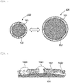
- a conventional negative electrode active material 100 has a negative electrode active material core material 101 and a film 102 formed on the surface of the negative electrode active material core material, and expansion and contraction are repeated by charge and discharge.
- the conventional film 102 does not have sufficient followability (or recoverability) to expansion and contraction, and therefore with the expansion and contraction, physical deterioration such as cracks 1020, pinholes 1021, and peeling 1022 from the negative electrode active material core material 101 easily occurred in the film 102 as shown in FIG. 4 .
- a new negative electrode material surface was generated to promote the decomposition of the electrolytic solution, and thus the cycle characteristics were rapidly deteriorated.
- FIG. 3 is a schematic sectional view of a negative electrode active material for explaining expansion and contraction in a conventional negative electrode active material.
- FIG. 4 is a schematic sectional view showing a surface state of a conventional negative electrode active material.
- An object of the present invention is to provide a negative electrode active material for a battery, exhibiting sufficiently excellent initial charge-discharge efficiency and cycle characteristics by suppressing physical deterioration of a film due to expansion and contraction of a core material.
- the present invention relates to a negative electrode active material for a battery, comprising:
- the negative electrode active material of the present invention can exhibit sufficiently excellent initial charge-discharge efficiency and cycle characteristics by suppressing physical deterioration (for example, cracking, pinholes, and peeling off from the negative electrode active material core material) of the film due to expansion and contraction of the core material.
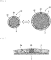
- a negative electrode active material 10 of the present invention has a negative electrode active material core material 1 and a film 2 formed on the surface of the negative electrode active material core material 1, and expansion and contraction may be repeated by charge and discharge.
- FIG. 1 is a schematic sectional view of a negative electrode active material for explaining expansion and contraction in the negative electrode active material of the present invention.
- the negative electrode active material core material 1 is a material that contributes to occlusion and release of ions that transfer electrons by moving between the positive electrode and the negative electrode, and is preferably a material that contributes to occlusion and release of lithium ions from the viewpoint of increasing the battery capacity.
- the negative electrode active material core material is preferably, for example, various silicon-based materials, carbon-based materials, or mixtures thereof. From the viewpoint of further increasing the battery capacity, the negative electrode active material core material is preferably a silicon-based material.
- the silicon-based material is a generic term for materials including silicon (Si) as a constituent element.
- the silicon-based material may be a simple substance of silicon, may be an alloy of silicon, or may be a compound of silicon.
- the silicon-based material may be a material having any one or two or more phases of the above simple substance, alloy, and compound in at least a part thereof.
- the silicon-based material may be crystalline or amorphous. Silicon shall be classified into the category of metals.
- the simple substance of silicon is a simple substance in a general sense. That is, the purity of the simple substance is not necessarily 100%, and the simple substance may include a trace amount of impurities.
- the alloy of silicon may include two or more of metal elements as constituent elements, or may include one or more of metal elements and one or more of metalloid elements as constituent elements.
- the alloy of silicon described above may further include one or more of nonmetallic elements as constituent elements.
- the structure of the alloy of silicon is, for example, a solid solution, a eutectic (eutectic mixture), an intermetallic compound, and a coexisting material of two or more thereof.
- the metal element and the metalloid element included as constituent elements in the alloy of silicon are, for example, any one or two or more of metal elements and metalloid elements capable of forming an alloy with the electrode reactant.
- the alloy of silicon includes, for example, any one or two or more of tin, nickel, copper, iron, cobalt, manganese, zinc, indium, silver, titanium, germanium, bismuth, antimony, and chromium as a constituent element other than silicon.
- the compound of silicon includes, for example, any one or two or more of carbon and oxygen as a constituent element other than silicon.
- the compound of silicon may include, for example, as a constituent element other than silicon, any one or two or more of the series of elements described for the alloy of silicon.
- Examples of the alloy of silicon and the compound of silicon include SiB 4 , SiB 6 , Mg 2 Si, Ni 2 Si, TiSi 2 , MoSi 2 , CoSi 2 , NiSi 2 , CaSi 2 , CrSi 2 , Cu 5 Si, FeSi 2 , MnSi 2 , NbSi 2 , TaSi 2 , VSi 2 , WSi 2 , ZnSi 2 , SiC, Si 3 N 4 , Si 2 N 2 O, SiO v (0 ⁇ v ⁇ 2), SiTi w (0 ⁇ w ⁇ 2), and LiSiO.
- v in SiO v may be 0.2 ⁇ v ⁇ 1.4.
- w in SiTi w may be 0.01 ⁇ v ⁇ 0.5.
- the carbon-based material is a generic term for materials including carbon as a constituent element.
- the type of the carbon-based material is not particularly limited, and examples thereof include graphitizable carbon, non-graphitizable carbon, and graphite (natural graphite, artificial graphite).
- the interplanar spacing of the (002) plane with respect to the non-graphitizable carbon is preferably, for example, 0.37 nm or more, and the interplanar spacing of the (002) plane with respect to the graphite is preferably, for example, 0.34 nm or less.
- examples of the carbon-based material include pyrolytic carbons, cokes, glassy carbon fibers, organic polymer compound fired bodies, activated carbon, and carbon blacks.
- the organic polymer compound fired body is a fired (carbonized) product of a polymer compound, and the polymer compound is, for example, any one or two or more of a phenol resin and a furan resin.
- the carbon-based material may be, for example, low crystalline carbon subjected to a heat treatment at a temperature of about 1000°C or less, or amorphous carbon.
- the carbon-based material may be hard carbon, soft carbon, or diamond-shaped carbon.
- the shape of the carbon-based material is not particularly limited, and is, for example, fibrous, spherical (particulate), and scaly. Of course, carbon-based materials having two or more types of shapes may be mixed.
- the negative electrode active material core material may be a metal oxide including a metal other than silicon.
- a metal oxide include at least one selected from the group consisting of tin oxide, indium oxide, zinc oxide, and lithium oxide.
- the average particle size of the negative electrode active material core material is not particularly limited, and may be, for example, 1 ⁇ m or more and 50 ⁇ m or less, particularly 1 ⁇ m or more and 40 ⁇ m or less.
- the average particle size described herein is the median diameter D50 ( ⁇ m), and the same applies hereinafter.
- the average particle size is preferably 1 ⁇ m or more and 10 ⁇ m or less from the viewpoint of suppressing side reactions of the electrolytic solution and suppressing expansion.
- the average particle size is preferably 5 ⁇ m or more and 40 ⁇ m or less from the viewpoint of suppressing side reactions of the electrolytic solution and suppressing expansion.
- a film 2 is an organic-inorganic hybrid film, and is formed of a composite of an organic component and an inorganic component.
- the film 2 is formed of a reactant including at least a first metal alkoxide and a second metal alkoxide as monomer components. More specifically, the film 2 is not formed by stacking a plurality of layers formed of each of the metal alkoxides; however, has a network structure (single layer structure) formed of a reactant of the metal alkoxide.
- the film 2 is composed of a reactant including at least a first metal alkoxide and a second metal alkoxide, and therefore has high flexibility (recoverability) and high resistance to expansion and contraction of the core material.
- the film 2 can sufficiently follow such expansion and contraction. Therefore, it is considered that physical deterioration of the film 2 due to expansion and contraction of the core material 1 can be sufficiently suppressed, and sufficiently excellent initial charge-discharge efficiency and cycle characteristics can be obtained. Details of the mechanism by which such an effect is obtained in the present invention are not clear; however, are considered to be based on the following mechanism.
- the film 2 is specifically composed of a reactant containing at least a first metal alkoxide and a second metal alkoxide, and therefore, as shown in FIG. 1 , the film 2 includes an inorganic portion 2a and an organic portion 2b.
- the inorganic portion 2a is a portion based on both the first metal alkoxide and the second metal alkoxide
- the organic portion 2b is a portion based on a part of the second metal alkoxide.
- the organic portion 2b has higher flexibility than the inorganic portion 2a, and therefore when a core material 1 expands (refer to the right side in FIG. 1 ) or contracts (refer to the left side in FIG. 1 ), it is possible to sufficiently suppress the physical deterioration of the film 2 by following the expansion and contraction of the core material as illustrated in FIG. 2 .
- the film 2 can be designed as an inorganic material having characteristics (flexibility) of the organic material by hybridization of an organic material and an inorganic material.
- an organic material represented by plastic is light, excellent in processability, and has flexibility and impact resistance. Whereas, the organic material is inferior in heat resistance and material stability to the inorganic material. In contrast, the inorganic material such as silica and glass is excellent in durability and heat resistance; however, is often heavy and vulnerable to impact (brittle, less flexible).
- the film 2 is an organic-inorganic hybrid material, and therefore it is possible to incorporate both of these characteristics. When the film does not include the second metal alkoxide, the film cannot sufficiently follow the expansion and contraction of the core material, thus the physical deterioration of the film is not sufficiently suppressed, and sufficiently excellent initial charge-discharge efficiency and cycle characteristics are not obtained.
- FIG. 2 is a schematic sectional view showing a surface state of the negative electrode active material of the present invention.
- the film 2 typically has an average film thickness of, for example, 0.1 nm or more and 20 nm or less (particularly 0.5 nm or more and 15 nm or less).
- the first metal alkoxide is a metal alkoxide including no metal atom-carbon atom bond in one molecule, and is a metal alkoxide in which all bonds of the metal are bonded to alkoxy groups (-OR 1 ).
- the metal atom-carbon atom bond is a direct covalent bond between a metal atom and a carbon atom.
- the carbon atom constituting the metal atom-carbon atom bond is a carbon atom constituting a monovalent hydrocarbon group (for example, an alkyl group and an alkenyl group) or a carbon atom constituting a divalent hydrocarbon group (for example, an alkylene group).
- the first metal alkoxide has no metal atom-carbon atom bond described above in one molecule. Therefore, the first metal alkoxide constitutes the film 2, and fixes the film 2 to the negative electrode active material core material 1 by relatively strong bonding.
- the first metal alkoxide is specifically a compound represented by the following general formula (1):
- M 1 is a metal atom and is Si, Ti, Al, or Zr, and is preferably Si, Ti, or Al, more preferably Si or Ti, and still more preferably Si, from the viewpoint of further improving the initial charge-discharge efficiency and cycle characteristics of the negative electrode active material.
- x is the valence of M 1 .
- M 1 is Si, Ti or Zr, x is 4.
- M 1 is Al, x is 3.
- Examples of the alkyl group as R 1 include a methyl group, an ethyl group, n-propyl, an isopropyl group, a n-butyl group, an isobutyl group, a sec-butyl group, a tert-butyl group, a n-pentyl group, a n-hexyl group, a n-heptyl group, a n-octyl group, a n-nonyl group, and a n-decyl group.
- all R 1 s may be each independently selected from the above alkyl groups, or all R 1 s may be mutually the same group selected from the above alkyl groups.
- R 2 is an alkyl group having 1 to 10 carbon atoms, and is preferably an alkyl group having 1 to 5 carbon atoms from the viewpoint of further improving the initial charge-discharge efficiency and cycle characteristics of the negative electrode active material.
- Examples of the alkyl group as R 2 include the same alkyl group as the alkyl group as R 1 .
- R 3 is an alkyl group having 1 to 30 carbon atoms, an alkyloxy group having 1 to 30 carbon atoms, or an alkenyloxy group having 1 to 30 carbon atoms, and from the viewpoint of further improving the initial charge-discharge efficiency and cycle characteristics of the negative electrode active material, R 3 is preferably an alkyl group having 1 to 20 carbon atoms (more preferably 1 to 10, still more preferably 1 to 5), an alkyloxy group having 10 to 30 carbon atoms (particularly 14 to 24), or an alkenyloxy group having 10 to 30 carbon atoms (particularly 14 to 24).
- the alkyl group as R 3 include an alkyl group similar to the alkyl group as R 1 , and an undecyl group, a lauryl group, a tridecyl group, a myristyl group, a pentadecyl group, a cetyl group, a heptadecyl group, a stearyl group, a nonadecyl group, and an eicosyl group.
- the alkyloxy group as R 3 include a group represented by the formula: -O-C p H 2p+1 (wherein p is an integer of 1 to 30).
- Examples of the alkyloxy group as R 3 include a group represented by the formula: -O-C q H 2q-1 (wherein q is an integer of 1 to 30).
- two adjacent R 1 s among a plurality of R 1 s may be bonded to each other to form one ring (for example, a 5 to 8 membered ring, particularly a 6 membered ring) together with an oxygen atom to which the two R 1 s are bonded and an M 1 atom to which the oxygen atom is bonded in the case of an alkyl group.
- Examples of one ring formed by bonding two adjacent R 1 s to each other include a 6-membered ring represented by general formula (1X): wherein, R 4 , R 5 , and R 6 are each independently a hydrogen atom or an alkyl group having 1 to 10 carbon atoms, and from the viewpoint of further improving the initial charge-discharge efficiency and cycle characteristics of the negative electrode active material, R 4 , R 5 , and R 6 are preferably a hydrogen atom or an alkyl group having 1 to 5 carbon atoms.
- the total number of carbon atoms of R 4 , R 5 , and R 6 is typically 0 to 12, and is preferably 2 to 8 from the viewpoint of further improving the initial charge-discharge efficiency and cycle characteristics of the negative electrode active material.
- examples of the alkyl group as R 4 , R 5 , and R 6 include the same alkyl group as the alkyl group as R 1 .
- the first metal alkoxide examples include compounds represented by the following general formulas (1A), (1B), (1B'), (1C), and (1D).
- the first metal alkoxide is preferably a compound represented by the general formula (1A), (1B), (1C), or (1D) or a mixture thereof, more preferably a compound represented by the general formula (1A), (1B), or (1C) or a mixture thereof, still more preferably a compound represented by the general formula (1A) or (1B) or a mixture thereof, and particularly preferably a compound represented by the general formula (1A) or a mixture thereof.
- R 1 is each independently the same R 1 as R 1 in the formula (1).
- R 1 is each independently preferably an alkyl group having 1 to 10 carbon atoms, more preferably 1 to 5 carbon atoms, from the viewpoint of further improving the initial charge-discharge efficiency and cycle characteristics of the negative electrode active material.
- R 1 is each independently the same R 1 as R 1 in the formula (1).
- R 2 and R 3 are preferably the following groups, respectively, from the viewpoint of further improving the initial charge-discharge efficiency and the cycle characteristics of the negative electrode active material.
- R 2 is an alkyl group having 1 to 10 carbon atoms, and preferably an alkyl group having 1 to 5 carbon atoms. Examples of the alkyl group as R 2 include the same alkyl group as the alkyl group as R 1 .
- R 3 is an alkyl group having 1 to 30 carbon atoms, and preferably an alkyl group having 1 to 20 (more preferably 1 to 10, still more preferably 1 to 5) carbon atoms.
- alkyl group as R 3 include an alkyl group similar to the alkyl group as R 1 , and an undecyl group, a lauryl group, a tridecyl group, a myristyl group, a pentadecyl group, a cetyl group, a heptadecyl group, a stearyl group, a nonadecyl group, and an eicosyl group.
- Ra 1 , Ra 2 , Ra 3 , Ra 4 , Ra 5 , and Ra 6 each independently represent a hydrogen atom or an alkyl group having 1 to 10 carbon atoms, and from the viewpoint of further improving the initial charge-discharge efficiency and the cycle characteristics of the negative electrode active material, Ra 1 , Ra 2 , Ra 3 , Ra 4 , Ra 5 , and Ra 6 each preferably represent an alkyl group having 1 to 5 carbon atoms.
- Alkyl groups as Ra 1 , Ra 2 , Ra 3 , Ra 4 , Ra 5 , and Ra 6 are the same alkyl groups as R 1 .
- R 1 is each independently the same R 1 as R 1 in the formula (1).
- R 2 and R 3 are preferably the following groups, respectively, from the viewpoint of further improving the initial charge-discharge efficiency and the cycle characteristics of the negative electrode active material.
- R 2 is an alkyl group having 1 to 10 carbon atoms, and preferably an alkyl group having 1 to 5 carbon atoms. Examples of the alkyl group as R 2 include the same alkyl group as the alkyl group as R 1 .
- R 3 is an alkyloxy group having 1 to 30 carbon atoms or an alkenyloxy group having 1 to 30 carbon atoms, and is preferably an alkyloxy group having 10 to 30 (particularly 14 to 24) carbon atoms or an alkenyloxy group having 10 to 30 (particularly 14 to 24) carbon atoms.
- Examples of the alkyloxy group as R 3 include a group represented by the formula: -O-C p H 2p+1 (wherein p is an integer of 1 to 30). Examples of the alkyloxy group as R 3 include a group represented by the formula: -O-C q H 2q-1 (wherein q is an integer of 1 to 30).
- R 1 is each independently the same R 1 as R 1 in the formula (1).
- R 1 is each independently preferably an alkyl group having 1 to 10 carbon atoms, more preferably 1 to 5 carbon atoms, from the viewpoint of further improving the initial charge-discharge efficiency and cycle characteristics of the negative electrode active material.
- a compound (1) represented by the general formula (1) can be obtained as a commercially available product, or can be produced by a known method.
- a compound (1A) can be obtained as commercially available tetraethyl orthosilicate (manufactured by Tokyo Chemical Industry Co., Ltd.).
- a compound (1B) can be obtained as commercially available tetrabutyl orthotitanate (manufactured by Tokyo Chemical Industry Co., Ltd.) and T-50 (manufactured by Nippon Soda Co., Ltd.).
- a compound (1B') can be obtained as commercially available TOG (manufactured by Nippon Soda Co., Ltd.).
- a compound (1C) can be obtained as commercially available aluminum triisopropoxide (manufactured by KANTO CHEMICAL CO., INC.).
- a compound (1D) can be obtained as commercially available zirconium (IV) tetrabutoxide, trade name TBZR (manufactured by Nippon Soda Co., Ltd.) or ZR-181 (manufactured by Nippon Soda Co., Ltd.).
- the content of the first metal alkoxide in the film 2 (that is, the reactant constituting the film) is typically 10% by mass or more and 95% by mass or less with respect to the total amount thereof (for example, the total amount of the first metal alkoxide and the second metal alkoxide), and from the viewpoint of further improving the initial charge-discharge efficiency of the negative electrode active material and the cycle characteristics, the content is preferably 20% by mass or more and 80% by mass or less, and more preferably 25% by mass or more and 75% by mass or less.
- the film may include two or more of the first metal alkoxides, and in this case, the total amount thereof may be within the above range.
- the second metal alkoxide is a metal alkoxide including two or more of (for example, 2 or more and 20 or less, preferably 2 or more and 10 or less, more preferably 2 or more and 5 or less) metal atom-carbon atom bonds in one molecule.
- the carbon atom constituting two or more of metal atom-carbon atom bonds is a carbon atom constituting a monovalent hydrocarbon group (for example, an alkyl group and an alkenyl group) and/or a carbon atom constituting a divalent hydrocarbon group (for example, an alkylene group).
- the carbon atom constituting all of two or more of metal atom-carbon atom bonds is preferably a carbon atom constituting a divalent hydrocarbon group (for example, an alkylene group) from the viewpoint of further improving the initial charge-discharge efficiency and cycle characteristics of the negative electrode active material.
- the metal atom of the second metal alkoxide is silicon.
- the second metal alkoxide includes two or more of such metal atom-carbon atom bonds in one molecule. Therefore, physical deterioration of the film is suppressed.
- the presence of the divalent hydrocarbon group causes the film to stretch and thus follow the core material during expansion of the core material.
- the carbon atom constituting the metal atom-carbon atom bond is a carbon atom constituting a monovalent hydrocarbon group (for example, an alkyl group and an alkenyl group)
- the film follows the core material while the monovalent hydrocarbon group exhibits a stress change relaxing action (for example, cushioning action) during contraction of the core material. It is considered that these results can sufficiently suppress physical deterioration of the film 2, and can provide sufficiently excellent initial charge-discharge efficiency and cycle characteristics.
- the second metal alkoxide is a compound having, in one molecule, two or more trialkoxysilyl groups represented by the following general formula (2): [Chemical Formula 2] -Si(OR 21 ) 3 (2) wherein, R 21 each independently represent an alkyl group having 1 to 10 carbon atoms, preferably an alkyl group having 1 to 5 carbon atoms, and more preferably an alkyl group having 1 to 3 carbon atoms, from the viewpoint of further improving the initial charge-discharge efficiency and cycle characteristics of the negative electrode active material.
- Examples of such an alkyl group include a methyl group, an ethyl group, n-propyl, an isopropyl group, a n-butyl group, an isobutyl group, a sec-butyl group, a tert-butyl group, a n-pentyl group, a n-hexyl group, a n-heptyl group, a n-octyl group, a n-nonyl group, and a n-decyl group.
- all of R 21 s may each independently be selected from the above alkyl groups, or all of R 21 s may be mutually the same group selected from the above alkyl groups.
- the trialkoxysilyl groups of the second metal alkoxide may be each independently selected from the trialkoxysilyl groups of the general formula (2), or may be mutually the same group.
- trialkoxysilyl group represented by the general formula (2) are shown in table below.
- Table 2 Specific examples of group of general formula (2) Group R 21 R 21 R 21 2A-1 Methyl group Methyl group Methyl group 2A-2 Ethyl group Ethyl group Ethyl group 2A-3 Isopropyl group Isopropyl group Isopropyl group 2A-4 Butyl group Butyl group Butyl group
- the second metal alkoxide may be, for example, a compound represented by the following general formula (2A), (2B), (2C), (2E), or (2F) or a mixture thereof.
- the second metal alkoxide is preferably a compound represented by the general formula (2A), (2E), or (2F) or a mixture thereof, and more preferably a compound represented by the general formula (2A), from the viewpoint of further improving the initial charge-discharge efficiency and cycle characteristics of the negative electrode active material.
- the second metal alkoxide may be, for example, a compound represented by the following general formula (2D) or a mixture thereof.
- R 211 and R 212 are each independently the same group as R 21 in the formula (2).
- three R 211 s and three R 212 s are each independently an alkyl group having 1 to 10 carbon atoms, and from the viewpoint of further improving the initial charge-discharge efficiency and cycle characteristics of the negative electrode active material, preferably an alkyl group having 1 to 5 carbon atoms, and more preferably an alkyl group having 1 to 3 carbon atoms.
- Three R 211 s and three R 212 s may be each independently selected from R 21 of the general formula (2), or may be mutually the same groups.
- R 31 is a divalent hydrocarbon group having 1 to 20 carbon atoms, and from the viewpoint of further improving the initial charge-discharge efficiency and cycle characteristics of the negative electrode active material, preferably a divalent hydrocarbon group having 1 to 10 carbon atoms, more preferably a divalent hydrocarbon group having 1 to 8 carbon atoms, and still more preferably a divalent hydrocarbon group having 1 to 5 (particularly 1 to 3) carbon atoms.
- the divalent hydrocarbon group as R 31 may be a divalent saturated aliphatic hydrocarbon group (for example, an alkylene group) or a divalent unsaturated aliphatic hydrocarbon group (for example, an alkenylene group).
- the divalent hydrocarbon group as R 31 is preferably a divalent saturated aliphatic hydrocarbon group (particularly an alkylene group) from the viewpoint of further improving the initial charge-discharge efficiency and cycle characteristics of the negative electrode active material.
- Examples of the divalent saturated aliphatic hydrocarbon group (particularly, an alkylene group) as R 31 include a group represented by -(CH 2 ) p - (wherein p is an integer of 1 to 20, preferably 1 to 10, more preferably 1 to 8, still more preferably 1 to 5 (particularly 1 to 3)).
- R 211 , R 212 , R 213 , and R 214 are the same groups as R 21 in the formula (2).
- three R 211 s, three R 212 s, three R 213 s, and three R 214 s are each independently an alkyl group having 1 to 10 carbon atoms, and from the viewpoint of further improving the initial charge-discharge efficiency and cycle characteristics of the negative electrode active material, preferably an alkyl group having 1 to 5 carbon atoms, and more preferably an alkyl group having 1 to 3 carbon atoms.
- Three R 211 s, three R 212 s, three R 213 s, and three R 214 s may be each independently selected from R 21 of the general formula (2), or may be mutually the same groups.
- R 32 is each independently a divalent hydrocarbon group having 1 to 20 carbon atoms, and from the viewpoint of further improving the initial charge-discharge efficiency and cycle characteristics of the negative electrode active material, preferably a divalent hydrocarbon group having 1 to 10 carbon atoms, and more preferably a divalent hydrocarbon group having 6 to 10 carbon atoms.
- the divalent hydrocarbon group as R 32 may be a divalent saturated aliphatic hydrocarbon group (for example, an alkylene group) or a divalent unsaturated aliphatic hydrocarbon group (for example, an alkenylene group).
- the divalent hydrocarbon group as R 32 is preferably a divalent saturated aliphatic hydrocarbon group (particularly an alkylene group) from the viewpoint of further improving the initial charge-discharge efficiency and cycle characteristics of the negative electrode active material.
- Examples of the divalent saturated aliphatic hydrocarbon group (particularly, an alkylene group) as R 32 include a group represented by - (CH 2 ) q - (wherein q is an integer of 1 to 10, more preferably 6 to 10). All of R 32 s may be each independently selected from the R 32 , or may be mutually the same group.
- R 33 is each independently a monovalent hydrocarbon group having 1 to 10 carbon atoms, and from the viewpoint of further improving the initial charge-discharge efficiency and cycle characteristics of the negative electrode active material, preferably a monovalent hydrocarbon group having 1 to 5 carbon atoms, and more preferably a monovalent hydrocarbon group having 1 to 3 carbon atoms.
- the monovalent hydrocarbon group as R 33 may be a saturated aliphatic hydrocarbon group (for example, an alkyl group) or an unsaturated aliphatic hydrocarbon group (for example, an alkenyl group).
- the monovalent hydrocarbon group as R 33 is preferably a saturated aliphatic hydrocarbon group (particularly an alkyl group) from the viewpoint of further improving the initial charge-discharge efficiency and cycle characteristics of the negative electrode active material.
- Examples of the monovalent saturated aliphatic hydrocarbon group (particularly, alkyl group) as R 33 include a methyl group, an ethyl group, a n-propyl group, an isopropyl group, a n-butyl group, an isobutyl group, a sec-butyl group, a tert-butyl group, a n-pentyl group, a n-hexyl group, a n-heptyl group, a n-octyl group, a n-nonyl group, and a n-decyl group. All of R 33 s may be each independently selected from the R 33 , or may be mutually the same group.
- R 211 and R 212 are the same groups as R 21 in the formula (2).
- three R 211 s and three R 212 s are each independently an alkyl group having 1 to 10 carbon atoms, and from the viewpoint of further improving the initial charge-discharge efficiency and cycle characteristics of the negative electrode active material, preferably an alkyl group having 1 to 5 carbon atoms, and more preferably an alkyl group having 1 to 3 carbon atoms.
- Three R 211 s and three R 212 s may be each independently selected from R 21 of the general formula (2), or may be mutually the same groups.
- R 34 , R 35 , and R 36 are each independently a divalent hydrocarbon group having 1 to 10 carbon atoms, and are preferably a divalent hydrocarbon group having 1 to 5 carbon atoms from the viewpoint of further improving the initial charge-discharge efficiency and cycle characteristics of the negative electrode active material.
- the divalent hydrocarbon group as R 34 , R 35 , and R 36 may be a divalent saturated aliphatic hydrocarbon group (for example, an alkylene group), or may be a divalent unsaturated aliphatic hydrocarbon group (for example, an alkenylene group).
- the divalent hydrocarbon group as R 34 , R 35 , and R 36 is preferably a divalent saturated aliphatic hydrocarbon group (particularly, an alkylene group) from the viewpoint of further improving the initial charge-discharge efficiency and cycle characteristics of the negative electrode active material.
- Examples of the divalent saturated aliphatic hydrocarbon group (particularly, an alkylene group) as R 34 , R 35 , and R 36 include a group represented by -(CH 2 ) r - (wherein r is an integer of 1 to 10, more preferably 1 to 5). All of R 34 , R 35 , and R 36 may be each independently selected from the divalent hydrocarbon group, or may be mutually the same group.
- the total number of carbon atoms of R 34 , R 35 , and R 36 is preferably 3 to 20, and more preferably 6 to 10, from the viewpoint of further improving the initial charge-discharge efficiency and cycle characteristics of the negative electrode active material.
- R 211 and R 212 are each independently the same group as R 21 in the formula (2).
- two R 211 s and two R 212 s are each independently an alkyl group having 1 to 10 carbon atoms, and from the viewpoint of further improving the initial charge-discharge efficiency and cycle characteristics of the negative electrode active material, preferably an alkyl group having 1 to 5 carbon atoms, and more preferably an alkyl group having 1 to 3 carbon atoms.
- Two R 211 s and two R 212 s may be each independently selected from R 21 of the general formula (2), or may be mutually the same groups.
- R 212 and R 213 are the same groups as R 21 in the formula (2).
- three R 212 s and three R 213 s are each independently an alkyl group having 1 to 10 carbon atoms, and from the viewpoint of further improving the initial charge-discharge efficiency and cycle characteristics of the negative electrode active material, preferably an alkyl group having 1 to 5 carbon atoms, and more preferably an alkyl group having 1 to 3 carbon atoms.
- Three R 212 s and three R 213 s may be each independently selected from R 21 of the general formula (2), or may be mutually the same groups.
- R 32 is each independently a divalent hydrocarbon group having 1 to 20 carbon atoms, and from the viewpoint of further improving the initial charge-discharge efficiency and cycle characteristics of the negative electrode active material, preferably a divalent hydrocarbon group having 1 to 10 carbon atoms, and more preferably a divalent hydrocarbon group having 4 to 8 carbon atoms.
- the divalent hydrocarbon group as R 32 may be a divalent saturated aliphatic hydrocarbon group (for example, an alkylene group) or a divalent unsaturated aliphatic hydrocarbon group (for example, an alkenylene group).
- the divalent hydrocarbon group as R 32 is preferably a divalent saturated aliphatic hydrocarbon group (particularly an alkylene group) from the viewpoint of further improving the initial charge-discharge efficiency and cycle characteristics of the negative electrode active material.
- Examples of the divalent saturated aliphatic hydrocarbon group (particularly, an alkylene group) as R 32 include a group represented by - (CH 2 ) q - (wherein q is an integer of 1 to 20, preferably 1 to 10, and more preferably 4 to 8). All of R 32 s may be each independently selected from the R 32 , or may be mutually the same group.
- R 33 is each independently a monovalent hydrocarbon group having 1 to 10 carbon atoms, and from the viewpoint of further improving the initial charge-discharge efficiency and cycle characteristics of the negative electrode active material, preferably a monovalent hydrocarbon group having 1 to 5 carbon atoms, and more preferably a monovalent hydrocarbon group having 1 to 3 carbon atoms.
- the monovalent hydrocarbon group as R 33 may be a saturated aliphatic hydrocarbon group (for example, an alkyl group) or an unsaturated aliphatic hydrocarbon group (for example, an alkenyl group).
- the monovalent hydrocarbon group as R 33 is preferably a saturated aliphatic hydrocarbon group (particularly an alkyl group) from the viewpoint of further improving the initial charge-discharge efficiency and cycle characteristics of the negative electrode active material.
- Examples of the monovalent saturated aliphatic hydrocarbon group (particularly, alkyl group) as R 33 include a methyl group, an ethyl group, a n-propyl group, an isopropyl group, a n-butyl group, an isobutyl group, a sec-butyl group, a tert-butyl group, a n-pentyl group, a n-hexyl group, a n-heptyl group, a n-octyl group, a n-nonyl group, and a n-decyl group. All of R 33 s may be each independently selected from the R 33 , or may be mutually the same group.
- R 34 is each independently a monovalent hydrocarbon group having 1 to 30 carbon atoms, and from the viewpoint of further improving the initial charge-discharge efficiency and cycle characteristics of the negative electrode active material, preferably a monovalent hydrocarbon group having 1 to 10 carbon atoms, and more preferably a monovalent hydrocarbon group having 1 to 5 carbon atoms.
- the monovalent hydrocarbon group as R 34 may be a saturated aliphatic hydrocarbon group (for example, an alkyl group) or an unsaturated aliphatic hydrocarbon group (for example, an alkenyl group).
- the monovalent hydrocarbon group as R 34 is preferably a saturated aliphatic hydrocarbon group (particularly an alkyl group) from the viewpoint of further improving the initial charge-discharge efficiency and cycle characteristics of the negative electrode active material.
- Examples of the monovalent saturated aliphatic hydrocarbon group (particularly, alkyl group) as R 34 include a methyl group, an ethyl group, a n-propyl group, an isopropyl group, a n-butyl group, an isobutyl group, a sec-butyl group, a tert-butyl group, a pentyl group, a hexyl group, a heptyl group, an octyl group, a nonyl group, a decyl group, an undecyl group, a dodecyl group, a tridecyl group, a tetradecyl group, a pentadecyl group, a hexadecyl group, a heptadecyl group, an octadecyl group, a nonadecyl group, and an eicosyl group. All of R 34 s may
- R 212 , R 213 , and R 214 are each independently the same group as R 21 in the formula (2).
- three R 212 s, three R 213 s, and three R 214 s are each independently an alkyl group having 1 to 10 carbon atoms, and from the viewpoint of further improving the initial charge-discharge efficiency and cycle characteristics of the negative electrode active material, preferably an alkyl group having 1 to 5 carbon atoms, and more preferably an alkyl group having 1 to 3 carbon atoms.
- Three R 212 s, three R 213 s, and three R 214 s may be each independently selected from R 21 of the general formula (2), or may be mutually the same groups.
- R 32 is each independently a divalent hydrocarbon group having 1 to 20 carbon atoms, and from the viewpoint of further improving the initial charge-discharge efficiency and cycle characteristics of the negative electrode active material, preferably a divalent hydrocarbon group having 1 to 10 carbon atoms, and more preferably a divalent hydrocarbon group having 1 to 5 carbon atoms.
- the divalent hydrocarbon group as R 32 may be a divalent saturated aliphatic hydrocarbon group (for example, an alkylene group) or a divalent unsaturated aliphatic hydrocarbon group (for example, an alkenylene group).
- the divalent hydrocarbon group as R 32 is preferably a divalent saturated aliphatic hydrocarbon group (particularly an alkylene group) from the viewpoint of further improving the initial charge-discharge efficiency and cycle characteristics of the negative electrode active material.
- Examples of the divalent saturated aliphatic hydrocarbon group (particularly, an alkylene group) as R 32 include a group represented by - (CH 2 ) q - (wherein q is an integer of 1 to 10, more preferably 1 to 5). All of R 32 s may be each independently selected from the R 32 , or may be mutually the same group.
- the compound (2A) represented by the general formula (2A), the compound (2B) represented by the general formula (2B), the compound (2C) represented by the general formula (2C), the compound (2D) represented by the general formula (2D), the compound (2E) represented by the general formula (2E), and the compound (2F) represented by the general formula (2F) can be obtained as commercially available products, or can be produced by a known method.
- the compound (2A) can be obtained as commercially available products, 1,2-bis(trimethoxysilyl)ethane (manufactured by Tokyo Chemical Industry Co., Ltd.) and 1,6-bis(trimethoxysilyl)hexane (manufactured by Tokyo Chemical Industry Co., Ltd.).
- the compound (2C) can be obtained as a commercially available product, X-12-5263HP (manufactured by Shin-Etsu Chemical Co., Ltd.).
- the compound (2D) can be obtained as a commercially available product, dimethyldimethoxysilane (manufactured by Tokyo Chemical Industry Co., Ltd.).
- the compound (2F) can be obtained as a commercially available product, tris[3-(trimethoxysilyl)-propyl]isocyanurate (manufactured by Tokyo Chemical Industry Co., Ltd.).
- the second metal alkoxide may be, for example, a compound represented by general formula (2A), (2B), (2C), (2D), (2E), or (2F), or a mixture thereof.
- the second metal alkoxide is preferably a compound represented by general formula (2A), (2D), (2E), or (2F) or a mixture thereof, and more preferably a compound represented by the general formula (2A) (particularly, R 31 is a divalent hydrocarbon group having 1 to 5 (preferably 1 to 3) carbon atoms; R 211 and R 212 are the same as R 211 and R 212 in the general formula (2A), respectively) or a compound represented by (2D), or a mixture thereof.
- the content of the second metal alkoxide in the film 2 (that is, the reactant constituting the film) is typically 5% by mass or more and 90% by mass or less with respect to the total amount thereof (for example, the total amount of the first metal alkoxide and the second metal alkoxide), and from the viewpoint of further improving the initial charge-discharge efficiency of the negative electrode active material and the cycle characteristics, the content is preferably 20% by mass or more and 80% by mass or less, and more preferably 25% by mass or more and 75% by mass or less.
- the film may include two or more of the second metal alkoxides, and in this case, the total amount thereof may be within the above range.
- the content (that is, the coating amount) of the film 2 in the negative electrode active material 10 is typically 0.20% by mass or more and 4.00% by mass or less with respect to the total amount (that is, the total amount of the negative electrode active material core material and the film) of the negative electrode active material 10, and from the viewpoint of further improving the initial charge-discharge efficiency of the negative electrode active material and the cycle characteristics, preferably 0.30% by mass or more and 3.20% by mass or less, and more preferably 0.30% by mass or more and 1.000% by mass or less.
- calculation was performed on the assumption that a total amount of alkoxide included in the metal alkoxide undergoes dehydration condensation reaction to provide a reaction product having no other structure change.
- the mass of the reaction product obtained by the dehydration condensation reaction of a total amount of alkoxide included in 1 g of 1,2-bis(trimethoxysilyl)ethane is 0.49 g.
- the negative electrode active material of the present invention can be produced by a method including stirring a negative electrode active material core material together with a first metal alkoxide and a second metal alkoxide in an alkaline solvent. After the stirring, specifically, the negative electrode active material core material is separated by filtration, washed, and dried by heating to provide a negative electrode active material that has included a film formed on the surface of the negative electrode active material core material.
- the coating method is not limited to the above method as long as coating can be performed on the active material core material, and may be performed by an application method such as spraying or dry mixing.
- the blending ratio (that is, the ratio of amount used) of the first metal alkoxide and the second metal alkoxide is typically the content ratio of each metal alkoxide in the film as it is, and thus may be a blending ratio according to a desired content ratio.
- the blending amount of the first metal alkoxide is typically 0.1 parts by mass or more and 20 parts by mass or less with respect to 100 parts by mass of the negative electrode active material core material, and from the viewpoint of further improving the initial charge-discharge efficiency and the cycle characteristics of the negative electrode active material, preferably 0.1 parts by mass or more and 10 parts by mass or less, and more preferably 0.5 parts by mass or more and 2.0 parts by mass or less.
- the blending amount of the second metal alkoxide is typically 0.1 parts by mass or more and 10 parts by mass or less with respect to 100 parts by mass of the negative electrode active material core material, and from the viewpoint of further improving the initial charge-discharge efficiency and the cycle characteristics of the negative electrode active material, preferably 0.1 parts by mass or more and 5 parts by mass or less, and more preferably 0.2 parts by mass or more and 1.8 parts by mass or less.
- the total blending amount of the first metal alkoxide and the second metal alkoxide is not particularly limited as long as a film is formed on the surface of the negative electrode active material core material, and is, for example, 0.5 parts by mass or more and 20 parts by mass or less with respect to 100 parts by mass of the negative electrode active material core material, and is preferably 0.5 parts by mass or more and 10 parts by mass or less, more preferably 0.8 parts by mass or more and 3.0 parts by mass or less from the viewpoint of further improving the initial charge-discharge efficiency and the cycle characteristics of the negative electrode active material. Adjusting the total blending amount can control the content (that is, the coating amount) of the film 2 in the negative electrode active material 10 described above. The coating amount increases as the total blending amount increases.
- the solvent is not particularly limited as long as it does not inhibit the reaction of each metal alkoxide of the first metal alkoxide and the second metal alkoxide, and for example, monoalcohols, ethers, glycols, or glycol ethers are preferable.
- the solvent can be monoalcohols such as methanol, ethanol, 1-propanol, 2-propanol, 1-butanol, 2-butanol, iso-butyl alcohol, 1-pentanol, 2-pentanol, and 2-methyl-2 pentanol; ethers such as 2-methoxyethanol, 2-ethoxyethanol, and 2-butoxyethanol; glycols such as ethylene glycol, diethylene glycol, triethylene glycol, and propylene glycol; and glycol ethers such as dipropylene glycol monomethyl ether, diethylene glycol monomethyl ether, diethylene glycol monoethyl ether, diethylene glycol monobutyl ether, triethylene glycol monomethyl ether, and diethylene glycol monohexyl ether.
- monoalcohols such as methanol, ethanol, 1-propanol, 2-propanol, 1-butanol, 2-butanol, iso-butyl alcohol, 1-pentanol, 2-p
- Preferable solvent is monoalcohols.
- water may be included as necessary.
- the above solvent may be used singly or in combination of two or more.
- the solvent may include various additives such as a catalyst, a pH adjusting agent, a stabilizer, and a thickener.
- the additive include an acid compound such as a boric acid compound and a base compound such as an ammonia compound.
- the blending amount of the solvent is not particularly limited as long as each metal alkoxide can be uniformly present on the surface of the negative electrode active material core material, and may be, for example, 20 parts by mass or more and 200 parts by mass or less, and particularly 30 parts by mass or more and 150 parts by mass or less with respect to 100 parts by mass of the negative electrode active material core material.
- the temperature of the mixture during stirring is not particularly limited as long as each metal alkoxide can be uniformly present on the surface of the negative electrode active material core material, and is, for example, 10°C or more and 70°C or less, preferably 15°C or more and 35°C or less.
- the stirring time is also not particularly limited as long as each metal alkoxide can be uniformly present on the surface of the negative electrode active material core material, and is, for example, 10 minutes or more and 5 hours or less, preferably 30 minutes or more and 3 hours or less.
- Washing is performed to remove the remaining catalyst.
- a filtration residue is brought into contact with a washing solvent.
- the washing solvent is not particularly limited, and may be, for example, acetone.
- the solvent used in the washing is removed by heating and drying.
- the heating temperature is typically 15°C or more (particularly, 15°C or more and 250°C or less), and is preferably 15°C or more and 200°C or less from the viewpoint of solvent removal.
- the heating time is typically 30 minutes or more (particularly, 30 minutes or more and 24 hours or less), and is preferably 60 minutes or more and 12 hours or less from the viewpoint of solvent removal.
- the negative electrode of the present invention is composed of at least a negative electrode layer and a negative electrode current collector (foil), and the negative electrode layer includes the above coated negative electrode active material.
- the coated negative electrode active material of the negative electrode layer is composed of, for example, a granular material, and a binder is preferably included in the negative electrode layer for sufficient contact between particles and shape retention.
- the negative electrode layer preferably further includes a conductive auxiliary agent in order to facilitate the transfer of electrons for promoting the battery reaction. As described above, a plurality of components are contained, and therefore the negative electrode layer can also be referred to as a "negative electrode mixture layer".
- the content of the negative electrode active material in the negative electrode layer is typically 50% by mass or more and 95% by mass or less with respect to the total amount of the negative electrode layer, and from the viewpoint of further improving the initial charge-discharge efficiency and cycle characteristics of the negative electrode active material, preferably 70% by mass or more and 95% by mass or less, and more preferably 85% by mass or more and 95% by mass or less.
- the negative electrode layer may include a conventional negative electrode active material together with the coated negative electrode active material.
- the content of the negative electrode active material is the content of all of the negative electrode active materials.
- the conventional negative electrode active material is, for example, a material that contributes to occlusion and release of lithium ions. From such a viewpoint, the conventional negative electrode active material is not particularly limited, and examples thereof include a silicon-based material, a carbon-based material, or a mixture thereof that can constitute the negative electrode active material core material of the coated negative electrode active material.
- the negative electrode layer preferably includes a carbon-based material (particularly, graphite, preferably artificial graphite) as a conventional negative electrode active material together with the coated negative electrode active material, from the viewpoint that the negative electrode layer more hardly expands and contracts during charge and discharge and the electrolytic solution is hardly decomposed while the secondary battery obtains a higher theoretical capacity (in other words, battery capacity).
- a carbon-based material particularly, graphite, preferably artificial graphite
- the mixing ratio of the coated negative electrode active material and the conventional negative electrode active material is typically 1/99 or more and 99/1 or less, and from the viewpoint of further improving the theoretical capacity (in other words, battery capacity) of the secondary battery, the expansion-and-contraction resistance of the negative electrode layer during charge and discharge, and the decomposition resistance of the electrolytic solution, preferably 10/90 or more and 50/50 or less, and more preferably 20/80 or more and 40/60 or less.
- the binder that can be included in the negative electrode layer is not particularly limited, and examples thereof include at least one selected from the group consisting of styrene butadiene rubber, polyacrylic acid and a salt thereof, polyurethane, polyvinylidene fluoride, a polyimide-based resin, a polyaramide-based resin, and a polyamideimide-based resin.
- the binder included in the negative electrode layer is polyvinylidene fluoride.
- the conductive auxiliary agent that can be included in the negative electrode layer is not particularly limited, and examples thereof include at least one selected from carbon black (including scaly carbon) such as thermal black, furnace black, channel black, ketjen black, and acetylene black, carbon fibers such as graphite, carbon nanotube, and vapor phase growth carbon fiber, metal powders such as copper, nickel, aluminum, and silver, and polyphenylene derivatives.
- the negative electrode layer may include a thickener component (for example, methyl cellulose) used in producing the battery.
- the thickness of the negative electrode layer after drying, pressing, and vacuum drying is not particularly limited, and may be, for example, 1 ⁇ m or more and 300 ⁇ m or less, particularly 5 ⁇ m or more and 100 ⁇ m or less.
- the thickness of the negative electrode layer is the thickness inside the secondary battery, and an average value of measured values at optional 50 locations is used.
- the negative electrode current collector is a member that contributes to collecting and supplying electrons generated in the active material due to the battery reaction.
- a current collector may be a sheet-shaped metal member and may have a porous or perforated form.
- the current collector may be a metal foil, a punching metal, a net, or an expanded metal.
- the negative electrode current collector used for the negative electrode is preferably composed of a metal foil including at least one selected from the group consisting of copper, stainless steel, and nickel, and for example, a copper foil may be included.
- the negative electrode layer may be provided on at least one surface of the negative electrode current collector.
- the negative electrode layer may be provided on both surfaces of the negative electrode current collector, or the negative electrode layer may be provided on one surface of the negative electrode current collector. From the viewpoint of further increasing the capacity of a battery (particularly a secondary battery), in a preferable negative electrode, negative electrode layers are provided on both surfaces of a negative electrode current collector.
- the negative electrode can be obtained, for example, by applying a negative electrode current collector with a negative electrode layer slurry prepared by mixing a negative electrode active material and a binder in a dispersion medium, drying the slurry, and then rolling a dried film with a roll press machine or the like.
- a coated negative electrode active material (and a conventional negative electrode active material when desired), a binder, and a dispersion medium (particularly, a non-aqueous solvent) are mixed. Thereafter, the mixture may be stirred.
- the stirring method and stirring conditions are not particularly limited, and for example, a stirring apparatus such as a mixer may be used.
- the type of the non-aqueous solvent is not particularly limited as long as it is any one or two or more among materials not only capable of dispersing the coated negative electrode active material (and the conventional negative electrode active material to be mixed when desired) but also capable of dissolving the binder.
- This non-aqueous solvent is, for example, an organic solvent such as N-methyl-2-pyrrolidone.
- the binder is dissolved by such a non-aqueous solvent, thus preparing a non-aqueous dispersion including the coated negative electrode active material (and the conventional negative electrode active material to be mixed when desired) and the binder.
- the state of this non-aqueous dispersion is not particularly limited, and is, for example, a paste.
- the paste non-aqueous dispersion is a so-called slurry.
- a negative electrode is produced by using the non-aqueous dispersion.
- the non-aqueous dispersion is applied onto both surfaces of the negative electrode current collector, and then the non-aqueous dispersion is dried.
- the negative electrode layer may be compression-molded by using a roll press machine or the like.
- the negative electrode layer may be heated, or compression-molding may be repeated a plurality of times.
- the compression condition and the heating condition are not particularly limited.
- the present invention provides a battery such as a secondary battery and a primary battery.
- a battery such as a secondary battery and a primary battery.
- the term “secondary battery” refers to a battery that can be repeatedly charged and discharged.
- the “secondary battery” is not excessively limited by its name, and can include, for example, a “power storage device”.
- the term “primary battery” refers to a battery capable of only discharging.
- the battery of the present invention is preferably a secondary battery.
- the secondary battery of the present invention includes the negative electrode described above.
- a positive electrode, a separator disposed between the positive electrode and the negative electrode, and an electrolyte are typically enclosed in an exterior body.
- the positive electrode, the negative electrode, and the separator disposed between the positive electrode and the negative electrode constitute an electrode assembly.
- the electrode assembly may have any structure as long as the above negative electrode (particularly, the above coated negative electrode active material) is included. This is because the effect of improving the initial charge-discharge efficiency and the cycle characteristics of the negative electrode active material can be obtained regardless of the structure of the electrode assembly.
- the structure that the electrode assembly can have include a laminated structure (planar laminated structure), a wound structure (jelly roll structure), and a stack-and-folding structure.
- the electrode assembly may have a planar laminated structure in which one or more positive electrodes and one or more negative electrodes are laminated in a planar shape with a separator interposed therebetween.
- the electrode assembly may have a wound structure (jelly roll type) in which a positive electrode, a negative electrode, and a separator disposed between the positive electrode and the negative electrode are wound in a roll shape.
- the electrode assembly may have a so-called stack-and-folding structure in which a positive electrode, a separator, and a negative electrode are laminated on a long film and then folded.
- the positive electrode is composed of at least a positive electrode layer and a positive electrode current collector (foil), and the positive electrode layer may be provided on at least one surface of the positive electrode current collector.
- the positive electrode layer may be provided on both surfaces of the positive electrode current collector, or the positive electrode layer may be provided on one surface of the positive electrode current collector.
- positive electrode layers are provided on both surfaces of a positive electrode current collector.
- the positive electrode layer includes a positive electrode active material.
- the negative electrode active material included in the negative electrode layer and the positive electrode active material included in the positive electrode layer are materials directly involved in the transfer of electrons in the secondary battery, and are main materials of the positive and negative electrodes serving charge and discharge, that is, a battery reaction. More specifically, ions are brought in an electrolyte due to "the positive electrode active material included in the positive electrode layer" and “the negative electrode active material included in the negative electrode layer”, and such ions move between the positive electrode and the negative electrode to transfer electrons, and charge and discharge are thus performed.
- the positive electrode and the negative electrode are preferably electrodes capable of occluding and releasing lithium ions, that is, the positive electrode layer and the negative electrode layer are preferably layers capable of occluding and releasing lithium ions. That is, there is preferable a secondary battery in which lithium ions move between the positive electrode and the negative electrode via the electrolyte to charge and discharge the battery.
- the secondary battery according to the present embodiment corresponds to a so-called "lithium ion battery".
- the positive electrode active material of the positive electrode layer is composed of, for example, a granular body, and preferably includes a binder for sufficient contact between particles and shape retention, and a conductive auxiliary agent may be included in the positive electrode layer in order to facilitate transfer of electrons for promoting a battery reaction.
- a plurality of components are included, and therefore the positive electrode layer can also be referred to as a "positive electrode mixture layer".
- the positive electrode active material is preferably a material that contributes to occlusion and release of lithium ions.
- the positive electrode active material is preferably, for example, a lithium-containing composite oxide.
- the positive electrode active material is preferably a lithium transition metal composite oxide including lithium and at least one transition metal selected from the group consisting of cobalt, nickel, manganese, and iron. That is, in the positive electrode layer of the secondary battery according to the present embodiment, such a lithium transition metal composite oxide is preferably included as a positive electrode active material.
- the positive electrode active material may be lithium cobaltate, lithium nickelate, lithium manganate, lithium iron phosphate, or a material obtained by replacing a part of these transition metals with another metal.
- Such a positive electrode active material may be included as a single species, or two or more species may be included in combination.
- the positive electrode active material included in the positive electrode layer is lithium cobalt oxide.
- the binder that can be included in the positive electrode layer is not particularly limited, and examples thereof include at least one selected from the group consisting of polyvinylidene fluoride, a vinylidene fluoride-hexafluoropropylene copolymer, a vinylidene fluoride-tetrafluoroethylene copolymer, and polytetrafluoroethylene.
- the binder of the positive electrode layer is polyvinylidene fluoride.
- the content of the binder in the positive electrode layer is typically 0.1% by mass or more and 20% by mass or less with respect to the total amount of the positive electrode layer, and from the viewpoint of further improving the initial charge-discharge efficiency of the negative electrode active material and the cycle characteristics, preferably 0.1% by mass or more and 10% by mass or less, and more preferably 0.5% by mass or more and 8% by mass or less.
- the conductive auxiliary agent that can be included in the positive electrode layer is not particularly limited, and examples thereof include at least one selected from carbon black such as thermal black, furnace black, channel black, ketjen black, and acetylene black, carbon fibers such as graphite, carbon nanotube, and vapor phase growth carbon fiber, metal powders such as copper, nickel, aluminum, and silver, and polyphenylene derivatives.
- the conductive auxiliary agent of the positive electrode layer is carbon black (particularly, ketjen black).
- the binder and the conductive auxiliary agent of the positive electrode layer are a combination of polyvinylidene fluoride and carbon black (particularly, ketjen black).
- the content of the conductive auxiliary agent in the positive electrode layer is typically 0.1% by mass or more and 20% by mass or less with respect to the total amount of the positive electrode layer, and from the viewpoint of further improving the initial charge-discharge efficiency of the negative electrode active material and the cycle characteristics, preferably 0.1% by mass or more and 10% by mass or less, and more preferably 0.5% by mass or more and 8% by mass or less.
- the thickness (after drying) of the positive electrode layer is not particularly limited, and may be, for example, 1 ⁇ m or more and 300 ⁇ m or less, particularly 5 ⁇ m or more and 200 ⁇ m or less.
- the thickness of the positive electrode layer is the thickness inside the battery (particularly, the secondary battery), and an average value of measured values at optional 50 locations is used.
- the positive electrode current collector is a member that contributes to collecting and supplying electrons generated in the active material due to the battery reaction.
- a current collector may be a sheet-shaped metal member and may have a porous or perforated form.
- the current collector may be a metal foil, a punching metal, a net, or an expanded metal.
- the positive electrode current collector used for the positive electrode is preferably composed of a metal foil including at least one selected from the group consisting of aluminum, stainless steel, and nickel, and the metal foil may be, for example, an aluminum foil.
- the positive electrode can be obtained, for example, by applying a positive electrode current collector with a positive electrode layer slurry prepared by mixing a positive electrode active material and a binder in a dispersion medium, drying the slurry, and then rolling a dried film with a roll press machine or the like.
- the separator is a member provided from the viewpoint of preventing a short circuit due to contact between the positive and negative electrodes and holding the electrolyte.
- the separator is a member that allows ions to pass while preventing electronic contact between the positive electrode and the negative electrode.
- the separator is a porous or microporous insulating member, and has a membrane form due to the small thickness thereof.
- a microporous membrane composed of polyolefin may be used as the separator.
- the microporous membrane used as the separator may include, for example, only polyethylene (PE) or only polypropylene (PP) as polyolefin.
- the separator may be a laminate composed of a "microporous membrane composed of PE” and a "microporous membrane composed of PP".
- the surface of the separator may be covered with an inorganic particle coating layer and/or an adhesive layer.
- the surface of the separator may have adhesiveness.
- the thickness of the separator is not particularly limited, and may be, for example, 1 ⁇ m or more and 100 ⁇ m or less, particularly 5 ⁇ m or more and 30 ⁇ m or less.
- the thickness of the separator is the thickness inside the secondary battery (particularly, the thickness between the positive electrode and the negative electrode), and the average value of the measured values at optional 50 locations is used.
- the electrolyte assists movement of metal ions released from the electrodes (positive electrode and negative electrode).
- the electrolyte may be a "non-aqueous" electrolyte, such as an organic electrolyte and an organic solvent, or an "aqueous” electrolyte including water.
- the secondary battery of the present invention is preferably a nonaqueous electrolyte secondary battery using an electrolyte including a "nonaqueous" solvent and a solute as an electrolyte.
- the electrolyte may have a form such as a liquid form or a gel form (in the present specification, the "liquid" nonaqueous electrolyte is also referred to as a "nonaqueous electrolyte solution").
- a solvent including at least carbonate is preferable as a specific solvent of the nonaqueous electrolyte.
- Such carbonates may be cyclic carbonates and/or chain carbonates.
- the cyclic carbonates are not particularly limited, and examples thereof include at least one selected from the group consisting of propylene carbonate (PC), ethylene carbonate (EC), butylene carbonate (BC), and vinylene carbonate (VC).
- Examples of the chain carbonates include at least one selected from the group consisting of dimethyl carbonate (DMC), diethyl carbonate (DEC), ethyl methyl carbonate (EMC), and dipropyl carbonate (DPC).
- DMC dimethyl carbonate
- DEC diethyl carbonate
- EMC ethyl methyl carbonate
- DPC dipropyl carbonate
- a combination of cyclic carbonates and chain carbonates is used as the nonaqueous electrolyte, and for example, a mixture of ethylene carbonate and ethyl methyl
- Li salts such as LiPF 6 and LiBF 4 are preferably used as a specific solute of the nonaqueous electrolyte.
- the exterior body is not particularly limited, and may be, for example, a flexible pouch (soft bag) or a hard case (hard case).
- the flexible pouch is typically formed of a laminate film, and sealing is achieved by heat-sealing the peripheral edge portion.
- a film obtained by laminating a metal foil and a polymer film is widely used as the laminate film, and specific examples thereof include a film having a three-layer structure of outer layer polymer film/metal foil/inner layer polymer film.
- the outer layer polymer film is a film for preventing damage to the metal foil from permeation and contact of moisture and the like, and polymers such as polyamide and polyester can be preferably used.
- the metal foil is a foil for preventing permeation of moisture and gas, and a foil such as copper, aluminum, and stainless steel can be preferably used.
- the inner layer polymer film is a film for protecting the metal foil from the electrolyte housed inside and a film for melt-sealing in heat sealing, and polyolefin (for example, polypropylene) or acid-modified polyolefin can be preferably used.
- the thickness of the laminate film is not particularly limited, and is preferably, for example, 1 ⁇ m or more and 1 mm or less.
- the hard case is typically formed of a metal plate, and sealing is achieved by irradiating the peripheral portion with laser.
- a metal material composed of aluminum, nickel, iron, copper, or stainless steel is widely used as the metal plate.
- the thickness of the metal plate is not particularly limited, and is preferably, for example, 1 ⁇ m or more and 1 mm or less.
- a Si-based material (that is, silicon oxide) was prepared as a negative electrode active material core material.
- SiO median diameter: 7 ⁇ m
- SiTi 0.3 median diameter: 3 ⁇ m
- polyvinylidene fluoride 1.00% by mass of acetylene black
- carbon nanotubes 0.05% by mass of carbon nanotubes
- a solvent that is, pure water
- This negative electrode layer slurry was applied onto one surface of a 12 ⁇ m copper foil, dried at 120°C, pressurized to 1.7 g/cc with a hand press machine, and then vacuum-dried to produce a silicon/graphite mixed negative electrode.
- the thickness of the negative electrode layer was 36 ⁇ m.
- a positive electrode active material LiCoO2
- a positive electrode binder polyvinylidene fluoride
- ketjen black positive electrode conductive agent
- organic solvent N-methyl-2-pyrrolidone
- the positive electrode layer was compression-molded by using a hand press machine, and then the positive electrode layer was vacuum-dried.
- a microporous film composed of polyethylene and having a thickness of 25 ⁇ m was used as a separator.
- R 211 s and two R 212 s may be each independently selected from R 21 of the general formula (2), or may be mutually the same groups.
- R 211 s and two R 212 s may be each independently selected from R 21 of the general formula (2), or may be mutually the same groups.
- R 211 s and two R 212 s may be each independently selected from R 21 of the general formula (2), or may be mutually the same groups.
- R 211 s and two R 212 s may be each independently selected from R 21 of the general formula (2), or may be mutually the same groups.
- the secondary battery was charged and discharged for one cycle in an ambient temperature environment (23°C) in order to stabilize the battery state.
- charge was performed at a current of 0.2 C until the voltage reached 4.4 V, and then charge was further performed at a voltage of 4.4 V until the current reached 0.025 C.
- discharge of the 1st cycle discharge was performed at a current of 0.2 C until the voltage reached 2.5 V. Then, the secondary battery was repeatedly charged and discharged until the total number of cycles reached 100 cycles in the same environment, and the discharge capacity was measured.
- R 211 s and two R 212 s may be each independently selected from R 21 of the general formula (2), or may be mutually the same groups.
- R 211 s and two R 212 s may be each independently selected from R 21 of the general formula (2), or may be mutually the same groups.
- R 211 s and two R 212 s may be each independently selected from R 21 of the general formula (2), or may be mutually the same groups.
- R 211 s and two R 212 s may be each independently selected from R 21 of the general formula (2), or may be mutually the same groups.
- R 211 s and two R 212 s may be each independently selected from R 21 of the general formula (2), or may be mutually the same groups.
- R 211 s and two R 212 s may be each independently selected from R 21 of the general formula (2), or may be mutually the same groups.
- R 211 s and two R 212 s may be each independently selected from R 21 of the general formula (2), or may be mutually the same groups.
- R 211 s and two R 212 s may be each independently selected from R 21 of the general formula (2), or may be mutually the same groups.
- the secondary battery was further charged and discharged for 3 cycles while changing the current during discharge in a normal temperature environment (23°C) by using the secondary battery (charged and discharged for 1 cycle) whose battery state was stabilized by the same procedure as in the case of examining the discharge capacity retention ratio (cycle characteristics), and the discharge capacities at the 2nd cycle and the 4th cycle were measured.
- charge of the 2nd to 4th cycles charge was performed at a current of 0.2 C until the voltage reached 4.4 V, and then charge was further performed at a voltage of 4.4 V until the current reached 0.025 C.
- discharge of the 2nd cycle discharge was performed at a current of 0.2 C until the voltage reached 2.5 V.
- the secondary battery according to the present invention can be used in various fields where electric storage is assumed.
- the secondary battery, particularly nonaqueous electrolyte secondary battery, according to the present invention can be used: in the fields of electricity, information, and communication (mobile device fields such as mobile phones, smartphones, smart watches, laptops, digital cameras, activity meters, arm computers, and electronic paper); in home and small industrial applications (for example, the fields of electric tools, golf carts, and home, nursing, and industrial robots); in large industrial applications (for example, the fields of forklift, elevator, and harbor crane); in transportation system fields (for example, the field of hybrid vehicles, electric vehicles, buses, trains, power-assisted bicycles, and electric two-wheeled vehicles); in power system applications (for example, the fields of various types of power generation, road conditioners, smart grids, and household power storage systems); in medical applications (medical equipment fields such as earphone hearing aids); in pharmaceutical applications (for example, the field of dosage management systems); and IoT fields and space and deep sea applications (for example
Landscapes
- Chemical & Material Sciences (AREA)
- Chemical Kinetics & Catalysis (AREA)
- Electrochemistry (AREA)
- General Chemical & Material Sciences (AREA)
- Engineering & Computer Science (AREA)
- Inorganic Chemistry (AREA)
- Manufacturing & Machinery (AREA)
- Composite Materials (AREA)
- Materials Engineering (AREA)
- Battery Electrode And Active Subsutance (AREA)
- Secondary Cells (AREA)
Abstract
Description
- The present invention relates to a negative electrode active material, a negative electrode, and a secondary battery.
- Conventionally, secondary batteries have been used as power sources for various electronic devices. A secondary battery generally has a structure in which an electrode assembly (electrode body) and an electrolyte are housed in an exterior body (case), and further includes an external terminal (or an electrode lead) for achieving electrical connection of the secondary battery. The electrode assembly has a structure in which a positive electrode and a negative electrode are disposed with a separator interposed therebetween.
- The positive electrode and the negative electrode have a positive electrode layer including a positive electrode active material and a negative electrode layer including a negative electrode active material, respectively. In the secondary battery, ions are brought in an electrolyte due to "the positive electrode active material included in the positive electrode layer" and "the negative electrode active material included in the negative electrode layer", and such ions move between the positive electrode and the negative electrode to transfer electrons, and charge and discharge are thus performed. In recent years, Li-ion secondary batteries using lithium ions as ions have been widely used as power sources for electronic devices because of excellent characteristics of high voltage and high energy density. Recently, miniaturization and high performance of electronic devices have been advanced, and there is an increasing demand for further increase in energy density of Li-ion secondary batteries.
- Current Li-ion secondary batteries mainly use LiCoO2 as a positive electrode and graphite as a negative electrode. Although graphite of the negative electrode is excellent in reversibility of charge and discharge, the discharge capacity thereof has already reached a value close to a theoretical value of 372 mAh/g corresponding to the interlayer compound LiC6. Therefore, in order to achieve higher energy density, it is necessary to develop a negative electrode material having a discharge capacity larger than that of graphite. As a negative electrode material in place of graphite, a Si-based material has attracted attention as an active material that forms an alloy with Li having a discharge capacity far exceeding that of graphite. Metal particles or alloy particles that occlude and release Li have a higher capacity density than graphite that has been conventionally used as a negative electrode active material. For this reason, using these as active materials can increase the capacity of the battery; however, these materials undergo volume expansion when absorbing Li and contract when releasing Li, and therefore there easily occur cracking of the particles themselves and cracking and peeling of a generated solid electrolyte interface film (hereinafter, referred to as "SEI film"). The expansion coefficient tends to increase as the metal or alloy has a higher capacity density. When the Si-based negative electrode material having a high capacity occludes Li, the Si-based negative electrode material expands up to about 4 times in volume, and thus cracking thereof or breakage of the formed SEI film particularly easily proceeds. For this reason, reductive decomposition of the electrolytic solution is promoted during charge, and cycle characteristics at a practical level are not obtained.
- Therefore, there has been disclosed a technique capable of suppressing decomposition of an electrolytic solution by coating a Si-based negative electrode material or the like with a specific metal oxide or metal (for example,
Patent Documents 1 to 4). -
- Patent Document 1:
Japanese Patent Application Laid-Open No. 2008-4534 - Patent Document 2: National Publication of International Patent Application No.
2016-507859 - Patent Document 3:
WO 2017/126337 - Patent Document 4:
Japanese Patent Application Laid-Open No. 2004-335334 - The inventors of the present invention have found that the following problems occur. Specifically, as shown in
FIG. 3 , a conventional negative electrodeactive material 100 has a negative electrode activematerial core material 101 and afilm 102 formed on the surface of the negative electrode active material core material, and expansion and contraction are repeated by charge and discharge. In this case, theconventional film 102 does not have sufficient followability (or recoverability) to expansion and contraction, and therefore with the expansion and contraction, physical deterioration such ascracks 1020,pinholes 1021, andpeeling 1022 from the negative electrode activematerial core material 101 easily occurred in thefilm 102 as shown inFIG. 4 . As a result, a new negative electrode material surface was generated to promote the decomposition of the electrolytic solution, and thus the cycle characteristics were rapidly deteriorated. In addition, the further decomposition of the electrolytic solution promoted the cracking of each part of the particles and the side reaction of the electrolytic solution, whereby the side reaction product further increased the particle volume or further deteriorated the charge-discharge efficiency.FIG. 3 is a schematic sectional view of a negative electrode active material for explaining expansion and contraction in a conventional negative electrode active material.FIG. 4 is a schematic sectional view showing a surface state of a conventional negative electrode active material. - An object of the present invention is to provide a negative electrode active material for a battery, exhibiting sufficiently excellent initial charge-discharge efficiency and cycle characteristics by suppressing physical deterioration of a film due to expansion and contraction of a core material.
- The present invention relates to a negative electrode active material for a battery, comprising:
- a negative electrode active material core material; and
- a film formed on a surface of the negative electrode active material core material, wherein
- the film is an organic-inorganic hybrid film composed of a reactant at least including:
- a first metal alkoxide including no metal atom-carbon atom bond in one molecule; and
- a second metal alkoxide including two or more of metal atom-carbon atom bonds in one molecule.
- The negative electrode active material of the present invention can exhibit sufficiently excellent initial charge-discharge efficiency and cycle characteristics by suppressing physical deterioration (for example, cracking, pinholes, and peeling off from the negative electrode active material core material) of the film due to expansion and contraction of the core material.
-
-
FIG. 1 is a schematic sectional view of a negative electrode active material for explaining expansion and contraction in the negative electrode active material of the present invention. -
FIG. 2 is a schematic sectional view showing a surface state of the negative electrode active material of the present invention. -
FIG. 3 is a schematic sectional view of a negative electrode active material for explaining expansion and contraction in a conventional negative electrode active material. -
FIG. 4 is a schematic sectional view showing a surface state of a conventional negative electrode active material. - As shown in
FIG. 1 , a negative electrodeactive material 10 of the present invention has a negative electrode activematerial core material 1 and afilm 2 formed on the surface of the negative electrode activematerial core material 1, and expansion and contraction may be repeated by charge and discharge.FIG. 1 is a schematic sectional view of a negative electrode active material for explaining expansion and contraction in the negative electrode active material of the present invention. - The negative electrode active
material core material 1 is a material that contributes to occlusion and release of ions that transfer electrons by moving between the positive electrode and the negative electrode, and is preferably a material that contributes to occlusion and release of lithium ions from the viewpoint of increasing the battery capacity. From such a viewpoint, the negative electrode active material core material is preferably, for example, various silicon-based materials, carbon-based materials, or mixtures thereof. From the viewpoint of further increasing the battery capacity, the negative electrode active material core material is preferably a silicon-based material. - The silicon-based material is a generic term for materials including silicon (Si) as a constituent element. The silicon-based material may be a simple substance of silicon, may be an alloy of silicon, or may be a compound of silicon. In addition, the silicon-based material may be a material having any one or two or more phases of the above simple substance, alloy, and compound in at least a part thereof. The silicon-based material may be crystalline or amorphous. Silicon shall be classified into the category of metals.
- The simple substance of silicon is a simple substance in a general sense. That is, the purity of the simple substance is not necessarily 100%, and the simple substance may include a trace amount of impurities.
- The alloy of silicon may include two or more of metal elements as constituent elements, or may include one or more of metal elements and one or more of metalloid elements as constituent elements. In addition, the alloy of silicon described above may further include one or more of nonmetallic elements as constituent elements. The structure of the alloy of silicon is, for example, a solid solution, a eutectic (eutectic mixture), an intermetallic compound, and a coexisting material of two or more thereof. The metal element and the metalloid element included as constituent elements in the alloy of silicon are, for example, any one or two or more of metal elements and metalloid elements capable of forming an alloy with the electrode reactant. Specific examples thereof include magnesium, boron, aluminum, gallium, indium, germanium, tin, lead, bismuth, cadmium, silver, zinc, hafnium, zirconium, yttrium, palladium, and platinum. The alloy of silicon includes, for example, any one or two or more of tin, nickel, copper, iron, cobalt, manganese, zinc, indium, silver, titanium, germanium, bismuth, antimony, and chromium as a constituent element other than silicon.
- The compound of silicon includes, for example, any one or two or more of carbon and oxygen as a constituent element other than silicon. The compound of silicon may include, for example, as a constituent element other than silicon, any one or two or more of the series of elements described for the alloy of silicon.
- Examples of the alloy of silicon and the compound of silicon include SiB4, SiB6, Mg2Si, Ni2Si, TiSi2, MoSi2, CoSi2, NiSi2, CaSi2, CrSi2, Cu5Si, FeSi2, MnSi2, NbSi2, TaSi2, VSi2, WSi2, ZnSi2, SiC, Si3N4, Si2N2O, SiOv (0 < v ≤ 2), SiTiw (0 < w ≤ 2), and LiSiO. v in SiOv may be 0.2 < v < 1.4. w in SiTiw may be 0.01 ≤ v ≤ 0.5.
- The carbon-based material is a generic term for materials including carbon as a constituent element. The type of the carbon-based material is not particularly limited, and examples thereof include graphitizable carbon, non-graphitizable carbon, and graphite (natural graphite, artificial graphite). However, the interplanar spacing of the (002) plane with respect to the non-graphitizable carbon is preferably, for example, 0.37 nm or more, and the interplanar spacing of the (002) plane with respect to the graphite is preferably, for example, 0.34 nm or less. More specifically, examples of the carbon-based material include pyrolytic carbons, cokes, glassy carbon fibers, organic polymer compound fired bodies, activated carbon, and carbon blacks. Examples of the cokes include pitch coke, needle coke, or petroleum coke. The organic polymer compound fired body is a fired (carbonized) product of a polymer compound, and the polymer compound is, for example, any one or two or more of a phenol resin and a furan resin. In addition, the carbon-based material may be, for example, low crystalline carbon subjected to a heat treatment at a temperature of about 1000°C or less, or amorphous carbon. The carbon-based material may be hard carbon, soft carbon, or diamond-shaped carbon.
- The shape of the carbon-based material is not particularly limited, and is, for example, fibrous, spherical (particulate), and scaly. Of course, carbon-based materials having two or more types of shapes may be mixed.
- The negative electrode active material core material may be a metal oxide including a metal other than silicon. Examples of such a metal oxide include at least one selected from the group consisting of tin oxide, indium oxide, zinc oxide, and lithium oxide.
- The average particle size of the negative electrode active material core material is not particularly limited, and may be, for example, 1 µm or more and 50 µm or less, particularly 1 µm or more and 40 µm or less. The average particle size described herein is the median diameter D50 (µm), and the same applies hereinafter.
- When the negative electrode active material core material is a silicon-based material, the average particle size (median diameter D50) is preferably 1 µm or more and 10 µm or less from the viewpoint of suppressing side reactions of the electrolytic solution and suppressing expansion.
- When the negative electrode active material core material is a carbon-based material, the average particle size (median diameter D50) is preferably 5 µm or more and 40 µm or less from the viewpoint of suppressing side reactions of the electrolytic solution and suppressing expansion.
- A
film 2 is an organic-inorganic hybrid film, and is formed of a composite of an organic component and an inorganic component. Specifically, thefilm 2 is formed of a reactant including at least a first metal alkoxide and a second metal alkoxide as monomer components. More specifically, thefilm 2 is not formed by stacking a plurality of layers formed of each of the metal alkoxides; however, has a network structure (single layer structure) formed of a reactant of the metal alkoxide. Thefilm 2 is composed of a reactant including at least a first metal alkoxide and a second metal alkoxide, and therefore has high flexibility (recoverability) and high resistance to expansion and contraction of the core material. Specifically, although the negative electrode active material core material repeats expansion and contraction by charge and discharge, thefilm 2 can sufficiently follow such expansion and contraction. Therefore, it is considered that physical deterioration of thefilm 2 due to expansion and contraction of thecore material 1 can be sufficiently suppressed, and sufficiently excellent initial charge-discharge efficiency and cycle characteristics can be obtained. Details of the mechanism by which such an effect is obtained in the present invention are not clear; however, are considered to be based on the following mechanism. Thefilm 2 is specifically composed of a reactant containing at least a first metal alkoxide and a second metal alkoxide, and therefore, as shown inFIG. 1 , thefilm 2 includes aninorganic portion 2a and anorganic portion 2b. Theinorganic portion 2a is a portion based on both the first metal alkoxide and the second metal alkoxide, and theorganic portion 2b is a portion based on a part of the second metal alkoxide. Theorganic portion 2b has higher flexibility than theinorganic portion 2a, and therefore when acore material 1 expands (refer to the right side inFIG. 1 ) or contracts (refer to the left side inFIG. 1 ), it is possible to sufficiently suppress the physical deterioration of thefilm 2 by following the expansion and contraction of the core material as illustrated inFIG. 2 . Thefilm 2 can be designed as an inorganic material having characteristics (flexibility) of the organic material by hybridization of an organic material and an inorganic material. For example, an organic material represented by plastic is light, excellent in processability, and has flexibility and impact resistance. Whereas, the organic material is inferior in heat resistance and material stability to the inorganic material. In contrast, the inorganic material such as silica and glass is excellent in durability and heat resistance; however, is often heavy and vulnerable to impact (brittle, less flexible). In the present invention, thefilm 2 is an organic-inorganic hybrid material, and therefore it is possible to incorporate both of these characteristics. When the film does not include the second metal alkoxide, the film cannot sufficiently follow the expansion and contraction of the core material, thus the physical deterioration of the film is not sufficiently suppressed, and sufficiently excellent initial charge-discharge efficiency and cycle characteristics are not obtained.FIG. 2 is a schematic sectional view showing a surface state of the negative electrode active material of the present invention. - The
film 2 typically has an average film thickness of, for example, 0.1 nm or more and 20 nm or less (particularly 0.5 nm or more and 15 nm or less). - The first metal alkoxide is a metal alkoxide including no metal atom-carbon atom bond in one molecule, and is a metal alkoxide in which all bonds of the metal are bonded to alkoxy groups (-OR1). In the first metal alkoxide, the metal atom-carbon atom bond is a direct covalent bond between a metal atom and a carbon atom. In the first metal alkoxide, the carbon atom constituting the metal atom-carbon atom bond is a carbon atom constituting a monovalent hydrocarbon group (for example, an alkyl group and an alkenyl group) or a carbon atom constituting a divalent hydrocarbon group (for example, an alkylene group). The first metal alkoxide has no metal atom-carbon atom bond described above in one molecule. Therefore, the first metal alkoxide constitutes the
film 2, and fixes thefilm 2 to the negative electrode activematerial core material 1 by relatively strong bonding. - The first metal alkoxide is specifically a compound represented by the following general formula (1):
- [Chemical Formula 1]
M1(OR1)x (1)
wherein, M1 is a metal atom and is Si, Ti, Al, or Zr, and is preferably Si, Ti, or Al, more preferably Si or Ti, and still more preferably Si, from the viewpoint of further improving the initial charge-discharge efficiency and cycle characteristics of the negative electrode active material. - x is the valence of M1. When M1 is Si, Ti or Zr, x is 4. When M1 is Al, x is 3.
- R1 is each independently an alkyl group having 1 to 10 carbon atoms or a group represented by the general formula: -C(R2)=CH-CO-R3 (wherein R2 and R3 are as described below), and is preferably an alkyl group having 1 to 5 carbon atoms from the viewpoint of further improving the initial charge-discharge efficiency and cycle characteristics of the negative electrode active material. Examples of the alkyl group as R1 include a methyl group, an ethyl group, n-propyl, an isopropyl group, a n-butyl group, an isobutyl group, a sec-butyl group, a tert-butyl group, a n-pentyl group, a n-hexyl group, a n-heptyl group, a n-octyl group, a n-nonyl group, and a n-decyl group. For a plurality of R1s according to the number of x, all R1s may be each independently selected from the above alkyl groups, or all R1s may be mutually the same group selected from the above alkyl groups.
- R2 is an alkyl group having 1 to 10 carbon atoms, and is preferably an alkyl group having 1 to 5 carbon atoms from the viewpoint of further improving the initial charge-discharge efficiency and cycle characteristics of the negative electrode active material. Examples of the alkyl group as R2 include the same alkyl group as the alkyl group as R1.
- R3 is an alkyl group having 1 to 30 carbon atoms, an alkyloxy group having 1 to 30 carbon atoms, or an alkenyloxy group having 1 to 30 carbon atoms, and from the viewpoint of further improving the initial charge-discharge efficiency and cycle characteristics of the negative electrode active material, R3 is preferably an alkyl group having 1 to 20 carbon atoms (more preferably 1 to 10, still more preferably 1 to 5), an alkyloxy group having 10 to 30 carbon atoms (particularly 14 to 24), or an alkenyloxy group having 10 to 30 carbon atoms (particularly 14 to 24). Preferable examples of the alkyl group as R3 include an alkyl group similar to the alkyl group as R1, and an undecyl group, a lauryl group, a tridecyl group, a myristyl group, a pentadecyl group, a cetyl group, a heptadecyl group, a stearyl group, a nonadecyl group, and an eicosyl group. Examples of the alkyloxy group as R3 include a group represented by the formula: -O-CpH2p+1 (wherein p is an integer of 1 to 30). Examples of the alkyloxy group as R3 include a group represented by the formula: -O-CqH2q-1 (wherein q is an integer of 1 to 30).
- In the formula (1), two adjacent R1s among a plurality of R1s may be bonded to each other to form one ring (for example, a 5 to 8 membered ring, particularly a 6 membered ring) together with an oxygen atom to which the two R1s are bonded and an M1 atom to which the oxygen atom is bonded in the case of an alkyl group. Examples of one ring formed by bonding two adjacent R1s to each other include a 6-membered ring represented by general formula (1X):

- Examples of the first metal alkoxide include compounds represented by the following general formulas (1A), (1B), (1B'), (1C), and (1D). From the viewpoint of further improving the initial charge-discharge efficiency and cycle characteristics of the negative electrode active material, the first metal alkoxide is preferably a compound represented by the general formula (1A), (1B), (1C), or (1D) or a mixture thereof, more preferably a compound represented by the general formula (1A), (1B), or (1C) or a mixture thereof, still more preferably a compound represented by the general formula (1A) or (1B) or a mixture thereof, and particularly preferably a compound represented by the general formula (1A) or a mixture thereof.
- [Chemical Formula 1A]
Si(OR1)4 (1A)
- In the formula (1A), R1 is each independently the same R1 as R1 in the formula (1). R1 is each independently preferably an alkyl group having 1 to 10 carbon atoms, more preferably 1 to 5 carbon atoms, from the viewpoint of further improving the initial charge-discharge efficiency and cycle characteristics of the negative electrode active material.
- Specific examples of a compound (1A) represented by such a general formula are shown in table below.
[Table 1A] Specific examples of compound (1A) Compound R1 R1 R1 R1 1A-1 Ethyl group Ethyl group Ethyl group Ethyl group 1A-2 Methyl group Methyl group Methyl group Methyl group 1A-3 Butyl group Butyl group Butyl group Butyl group 1A-4 Isopropyl group Isopropyl group Isopropyl group Isopropyl group - [Chemical Formula 1B1]
Ti(OR1)4 (1B)
- In the formula (1B), R1 is each independently the same R1 as R1 in the formula (1). From the viewpoint of further improving the initial charge-discharge efficiency and cycle characteristics of the negative electrode active material, R1 is each independently preferably an alkyl group having 1 to 10 carbon atoms or a group represented by the general formula: -C(R2)=CH-CO-R3 (wherein R2 and R3 are the same as R2 and R3 described in the general formula (1), respectively), and more preferably an alkyl group having 1 to 10 (particularly 1 to 5) carbon atoms.
- In the formula (1B), R2 and R3 are preferably the following groups, respectively, from the viewpoint of further improving the initial charge-discharge efficiency and the cycle characteristics of the negative electrode active material. R2 is an alkyl group having 1 to 10 carbon atoms, and preferably an alkyl group having 1 to 5 carbon atoms. Examples of the alkyl group as R2 include the same alkyl group as the alkyl group as R1. R3 is an alkyl group having 1 to 30 carbon atoms, and preferably an alkyl group having 1 to 20 (more preferably 1 to 10, still more preferably 1 to 5) carbon atoms. Preferable examples of the alkyl group as R3 include an alkyl group similar to the alkyl group as R1, and an undecyl group, a lauryl group, a tridecyl group, a myristyl group, a pentadecyl group, a cetyl group, a heptadecyl group, a stearyl group, a nonadecyl group, and an eicosyl group.
- Specific examples of a compound (1B) represented by such a general formula are shown in table below.
[Table 1B1] Specific examples of compound (1B) Compound R1 R1 R1 R1 1B-1 Butyl group Butyl group Butyl group Butyl group 1B-2 Isopropyl group Isopropyl group Isopropyl group Isopropyl group 1B-3 Ethyl group Ethyl group Ethyl group Ethyl group 1B-4 Methyl group Methyl group Methyl group Methyl group 1B-5 Isopropyl group Isopropyl group -C(CH3)=CH-CO-CH3 -C(CH3)=CH-CO-CH3 1B-6 Isopropyl group Isopropyl group -C(CH3)=CH-CO-C2H5 -C(CH3)=CH-CO-C2H5 1B-7 Butyl group Butyl group -C(CH3)=CH-CO-CH3 -C(CH3)=CH-CO-CH3 1B-8 Butyl group Butyl group -C(CH3)=CH-CO-C2H5 -C(CH3)=CH-CO-C2H5 1B-9 Ethyl group Ethyl group -C(CH3)=CH-CO-CH3 -C(CH3)=CH-CO-CH3 1B-10 Ethyl group Ethyl group -C(CH3)=CH-CO-C2H5 -C(CH3)=CH-CO-C2H5 1B-11 Methyl group Methyl group -C(CH3)=CH-CO-CH3 -C(CH3)=CH-CO-CH3 1B-12 Methyl group Methyl group -C(CH3)=CH-CO-C2H5 -C(CH3)=CH-CO-C2H5 
- In the formula (1B'), Ra1, Ra2, Ra3, Ra4, Ra5, and Ra6 each independently represent a hydrogen atom or an alkyl group having 1 to 10 carbon atoms, and from the viewpoint of further improving the initial charge-discharge efficiency and the cycle characteristics of the negative electrode active material, Ra1, Ra2, Ra3, Ra4, Ra5, and Ra6 each preferably represent an alkyl group having 1 to 5 carbon atoms. Alkyl groups as Ra1, Ra2, Ra3, Ra4, Ra5, and Ra6 are the same alkyl groups as R1.
- Specific examples of a compound (1B') represented by such a general formula are shown in table below.
[Table 1B2] Specific examples of compound (1B') Compound Ra1 Ra2 Ra3 Ra4 Ra5 Ra6 1B'-1 n-propyl group Ethyl group Hydrogen atom n-propyl group Ethyl group Hydrogen atom - [Chemical Formula 1C]
Al(OR1)3 (1C)
- In the formula (1C), R1 is each independently the same R1 as R1 in the formula (1). From the viewpoint of further improving the initial charge-discharge efficiency and cycle characteristics of the negative electrode active material, R1 is each independently preferably an alkyl group having 1 to 10 carbon atoms or a group represented by the general formula: -C(R2)=CH-CO-R3 (wherein R2 and R3 are the same as R2 and R3 described in the general formula (1), respectively), and more preferably an alkyl group having 1 to 10 (particularly 1 to 5) carbon atoms.
- In the formula (1C), R2 and R3 are preferably the following groups, respectively, from the viewpoint of further improving the initial charge-discharge efficiency and the cycle characteristics of the negative electrode active material. R2 is an alkyl group having 1 to 10 carbon atoms, and preferably an alkyl group having 1 to 5 carbon atoms. Examples of the alkyl group as R2 include the same alkyl group as the alkyl group as R1. R3 is an alkyloxy group having 1 to 30 carbon atoms or an alkenyloxy group having 1 to 30 carbon atoms, and is preferably an alkyloxy group having 10 to 30 (particularly 14 to 24) carbon atoms or an alkenyloxy group having 10 to 30 (particularly 14 to 24) carbon atoms. Examples of the alkyloxy group as R3 include a group represented by the formula: -O-CpH2p+1 (wherein p is an integer of 1 to 30). Examples of the alkyloxy group as R3 include a group represented by the formula: -O-CqH2q-1 (wherein q is an integer of 1 to 30).
- Specific examples of a compound (1C) represented by such a general formula are shown in table below.
[Table 1C] Specific examples of compound (1C) Compound R1 R1 R1 1C-1 Isopropyl group Isopropyl group Isopropyl group 1C-2 Sec-butyl group Sec-butyl group Sec-butyl group 1C-3 Ethyl group Ethyl group Ethyl group 1C-4 Methyl group Methyl group Methyl group 1C-5 Isopropyl group Isopropyl group -C(CH3)=CH-CO-C18H35 1C-6 Isopropyl group Isopropyl group -C(CH3)=CH-CO-C18H37 1C-7 Sec-butyl group Sec-butyl group -C(CH3)=CH-CO-C18H35 1C-8 Sec-butyl group Sec-butyl group -C(CH3)=CH-CO-C18H37 1C-9 Ethyl group Ethyl group -C(CH3)=CH-CO-C18H35 1C-10 Ethyl group Ethyl group -C(CH3)=CH-CO-C18H37 1C-11 Methyl group Methyl group -C(CH3)=CH-CO-C18H35 1C-12 Methyl group Methyl group -C(CH3)=CH-CO-C18H37 - [Chemical Formula 1D]
Zr(OR1)4 (1D)
- In the formula (1D), R1 is each independently the same R1 as R1 in the formula (1). R1 is each independently preferably an alkyl group having 1 to 10 carbon atoms, more preferably 1 to 5 carbon atoms, from the viewpoint of further improving the initial charge-discharge efficiency and cycle characteristics of the negative electrode active material.
- Specific examples of a compound (1D) represented by such a general formula are shown in table below.
[Table 1D] Specific examples of compound (1D) Compound R1 R1 R1 R1 1D-1 Isopropyl group Isopropyl group Isopropyl group Isopropyl group 1D-2 Butyl group Butyl group Butyl group Butyl group 1D-3 Ethyl group Ethyl group Ethyl group Ethyl group 1D-4 Methyl group Methyl group Methyl group Methyl group - A compound (1) represented by the general formula (1) can be obtained as a commercially available product, or can be produced by a known method.
- For example, a compound (1A) can be obtained as commercially available tetraethyl orthosilicate (manufactured by Tokyo Chemical Industry Co., Ltd.).
- In addition, for example, a compound (1B) can be obtained as commercially available tetrabutyl orthotitanate (manufactured by Tokyo Chemical Industry Co., Ltd.) and T-50 (manufactured by Nippon Soda Co., Ltd.).
- In addition, for example, a compound (1B') can be obtained as commercially available TOG (manufactured by Nippon Soda Co., Ltd.).
- In addition, for example, a compound (1C) can be obtained as commercially available aluminum triisopropoxide (manufactured by KANTO CHEMICAL CO., INC.).
- In addition, for example, a compound (1D) can be obtained as commercially available zirconium (IV) tetrabutoxide, trade name TBZR (manufactured by Nippon Soda Co., Ltd.) or ZR-181 (manufactured by Nippon Soda Co., Ltd.).
- The content of the first metal alkoxide in the film 2 (that is, the reactant constituting the film) is typically 10% by mass or more and 95% by mass or less with respect to the total amount thereof (for example, the total amount of the first metal alkoxide and the second metal alkoxide), and from the viewpoint of further improving the initial charge-discharge efficiency of the negative electrode active material and the cycle characteristics, the content is preferably 20% by mass or more and 80% by mass or less, and more preferably 25% by mass or more and 75% by mass or less. The film may include two or more of the first metal alkoxides, and in this case, the total amount thereof may be within the above range.
- The second metal alkoxide is a metal alkoxide including two or more of (for example, 2 or more and 20 or less, preferably 2 or more and 10 or less, more preferably 2 or more and 5 or less) metal atom-carbon atom bonds in one molecule. In the second metal alkoxide, the carbon atom constituting two or more of metal atom-carbon atom bonds is a carbon atom constituting a monovalent hydrocarbon group (for example, an alkyl group and an alkenyl group) and/or a carbon atom constituting a divalent hydrocarbon group (for example, an alkylene group). In the second metal alkoxide, the carbon atom constituting all of two or more of metal atom-carbon atom bonds is preferably a carbon atom constituting a divalent hydrocarbon group (for example, an alkylene group) from the viewpoint of further improving the initial charge-discharge efficiency and cycle characteristics of the negative electrode active material. The metal atom of the second metal alkoxide is silicon. The second metal alkoxide includes two or more of such metal atom-carbon atom bonds in one molecule. Therefore, physical deterioration of the film is suppressed. Specifically, for example, in the second metal alkoxide, when the carbon atom constituting the metal atom-carbon atom bond is a carbon atom constituting a divalent hydrocarbon group (for example, an alkylene group), the presence of the divalent hydrocarbon group causes the film to stretch and thus follow the core material during expansion of the core material. In addition, for example, in the second metal alkoxide, when the carbon atom constituting the metal atom-carbon atom bond is a carbon atom constituting a monovalent hydrocarbon group (for example, an alkyl group and an alkenyl group), the film follows the core material while the monovalent hydrocarbon group exhibits a stress change relaxing action (for example, cushioning action) during contraction of the core material. It is considered that these results can sufficiently suppress physical deterioration of the
film 2, and can provide sufficiently excellent initial charge-discharge efficiency and cycle characteristics. - When the carbon atom constituting the metal atom-carbon atom bond in the second metal alkoxide is a carbon atom constituting a divalent hydrocarbon group, the second metal alkoxide is a compound having, in one molecule, two or more trialkoxysilyl groups represented by the following general formula (2):
[Chemical Formula 2]
-Si(OR21)3 (2)
wherein, R21 each independently represent an alkyl group having 1 to 10 carbon atoms, preferably an alkyl group having 1 to 5 carbon atoms, and more preferably an alkyl group having 1 to 3 carbon atoms, from the viewpoint of further improving the initial charge-discharge efficiency and cycle characteristics of the negative electrode active material. Examples of such an alkyl group include a methyl group, an ethyl group, n-propyl, an isopropyl group, a n-butyl group, an isobutyl group, a sec-butyl group, a tert-butyl group, a n-pentyl group, a n-hexyl group, a n-heptyl group, a n-octyl group, a n-nonyl group, and a n-decyl group. For a plurality of R21s, all of R21s may each independently be selected from the above alkyl groups, or all of R21s may be mutually the same group selected from the above alkyl groups. - The trialkoxysilyl groups of the second metal alkoxide may be each independently selected from the trialkoxysilyl groups of the general formula (2), or may be mutually the same group.
- Specific examples of the trialkoxysilyl group represented by the general formula (2) are shown in table below.
[Table 2] Specific examples of group of general formula (2) Group R21 R21 R21 2A-1 Methyl group Methyl group Methyl group 2A-2 Ethyl group Ethyl group Ethyl group 2A-3 Isopropyl group Isopropyl group Isopropyl group 2A-4 Butyl group Butyl group Butyl group - When all carbon atoms constituting two or more of metal atom-carbon atom bonds in the second metal alkoxide are carbon atoms constituting a divalent hydrocarbon group, the second metal alkoxide may be, for example, a compound represented by the following general formula (2A), (2B), (2C), (2E), or (2F) or a mixture thereof. Of these, the second metal alkoxide is preferably a compound represented by the general formula (2A), (2E), or (2F) or a mixture thereof, and more preferably a compound represented by the general formula (2A), from the viewpoint of further improving the initial charge-discharge efficiency and cycle characteristics of the negative electrode active material.
- When all carbon atoms constituting two or more of metal atom-carbon atom bonds in the second metal alkoxide are carbon atoms constituting a monovalent hydrocarbon group, the second metal alkoxide may be, for example, a compound represented by the following general formula (2D) or a mixture thereof.
- [Chemical Formula 2A]
(R211O)3Si-R31-Si(OR212)3 (2A)
- In the formula (2A), R211 and R212 are each independently the same group as R21 in the formula (2). Specifically, three R211s and three R212s are each independently an alkyl group having 1 to 10 carbon atoms, and from the viewpoint of further improving the initial charge-discharge efficiency and cycle characteristics of the negative electrode active material, preferably an alkyl group having 1 to 5 carbon atoms, and more preferably an alkyl group having 1 to 3 carbon atoms. Three R211s and three R212s may be each independently selected from R21 of the general formula (2), or may be mutually the same groups.
- R31 is a divalent hydrocarbon group having 1 to 20 carbon atoms, and from the viewpoint of further improving the initial charge-discharge efficiency and cycle characteristics of the negative electrode active material, preferably a divalent hydrocarbon group having 1 to 10 carbon atoms, more preferably a divalent hydrocarbon group having 1 to 8 carbon atoms, and still more preferably a divalent hydrocarbon group having 1 to 5 (particularly 1 to 3) carbon atoms. The divalent hydrocarbon group as R31 may be a divalent saturated aliphatic hydrocarbon group (for example, an alkylene group) or a divalent unsaturated aliphatic hydrocarbon group (for example, an alkenylene group). The divalent hydrocarbon group as R31 is preferably a divalent saturated aliphatic hydrocarbon group (particularly an alkylene group) from the viewpoint of further improving the initial charge-discharge efficiency and cycle characteristics of the negative electrode active material. Examples of the divalent saturated aliphatic hydrocarbon group (particularly, an alkylene group) as R31 include a group represented by -(CH2)p- (wherein p is an integer of 1 to 20, preferably 1 to 10, more preferably 1 to 8, still more preferably 1 to 5 (particularly 1 to 3)).
- Specific examples of a compound (2A) represented by such a general formula are shown in table below.
[Table 2A] Specific examples of compound (2A) Compound R211 R211 R211 R31 R212 R212 R212 2A-1 Methyl group Methyl group Methyl group -CH2CH2- Methyl group Methyl group Methyl group 2A-2 Methyl group Methyl group Methyl group -CH2CH2CH2CH2CH2CH2- Methyl group Methyl group Methyl group 2A-3 Ethyl group Ethyl group Ethyl group -CH2CH2- Ethyl group Ethyl group Ethyl group 2A-4 Ethyl group Ethyl group Ethyl group -CH2CH2CH2CH2CH2CH2- Ethyl group Ethyl group Ethyl group 
- In the formula (2B), R211, R212, R213, and R214 are the same groups as R21 in the formula (2). Specifically, three R211s, three R212s, three R213s, and three R214s are each independently an alkyl group having 1 to 10 carbon atoms, and from the viewpoint of further improving the initial charge-discharge efficiency and cycle characteristics of the negative electrode active material, preferably an alkyl group having 1 to 5 carbon atoms, and more preferably an alkyl group having 1 to 3 carbon atoms. Three R211s, three R212s, three R213s, and three R214s may be each independently selected from R21 of the general formula (2), or may be mutually the same groups.
- R32 is each independently a divalent hydrocarbon group having 1 to 20 carbon atoms, and from the viewpoint of further improving the initial charge-discharge efficiency and cycle characteristics of the negative electrode active material, preferably a divalent hydrocarbon group having 1 to 10 carbon atoms, and more preferably a divalent hydrocarbon group having 6 to 10 carbon atoms. The divalent hydrocarbon group as R32 may be a divalent saturated aliphatic hydrocarbon group (for example, an alkylene group) or a divalent unsaturated aliphatic hydrocarbon group (for example, an alkenylene group). The divalent hydrocarbon group as R32 is preferably a divalent saturated aliphatic hydrocarbon group (particularly an alkylene group) from the viewpoint of further improving the initial charge-discharge efficiency and cycle characteristics of the negative electrode active material. Examples of the divalent saturated aliphatic hydrocarbon group (particularly, an alkylene group) as R32 include a group represented by - (CH2)q- (wherein q is an integer of 1 to 10, more preferably 6 to 10). All of R32s may be each independently selected from the R32, or may be mutually the same group.
- R33 is each independently a monovalent hydrocarbon group having 1 to 10 carbon atoms, and from the viewpoint of further improving the initial charge-discharge efficiency and cycle characteristics of the negative electrode active material, preferably a monovalent hydrocarbon group having 1 to 5 carbon atoms, and more preferably a monovalent hydrocarbon group having 1 to 3 carbon atoms. The monovalent hydrocarbon group as R33 may be a saturated aliphatic hydrocarbon group (for example, an alkyl group) or an unsaturated aliphatic hydrocarbon group (for example, an alkenyl group). The monovalent hydrocarbon group as R33 is preferably a saturated aliphatic hydrocarbon group (particularly an alkyl group) from the viewpoint of further improving the initial charge-discharge efficiency and cycle characteristics of the negative electrode active material. Examples of the monovalent saturated aliphatic hydrocarbon group (particularly, alkyl group) as R33 include a methyl group, an ethyl group, a n-propyl group, an isopropyl group, a n-butyl group, an isobutyl group, a sec-butyl group, a tert-butyl group, a n-pentyl group, a n-hexyl group, a n-heptyl group, a n-octyl group, a n-nonyl group, and a n-decyl group. All of R33s may be each independently selected from the R33, or may be mutually the same group.
- Specific examples of a compound (2B) represented by such a general formula are shown in table below.
[Table 2B] Specific examples of compound (2B) Compound Three R211s, three R212s, three R213s, three R214s Four R32s Four R33s 2B-1 Methyl group -CH2CH2CH2CH2CH2CH2CH2CH2- Methyl group 2B-2 Ethyl group -CH2CH2CH2CH2CH2CH2CH2CH2- Methyl group - [Chemical Formula 2C]
(R211O)3Si-R34-NH-R35-NH-R36-Si(OR212)3 (2C)
- In the formula (2C), R211 and R212 are the same groups as R21 in the formula (2). Specifically, three R211s and three R212s are each independently an alkyl group having 1 to 10 carbon atoms, and from the viewpoint of further improving the initial charge-discharge efficiency and cycle characteristics of the negative electrode active material, preferably an alkyl group having 1 to 5 carbon atoms, and more preferably an alkyl group having 1 to 3 carbon atoms. Three R211s and three R212s may be each independently selected from R21 of the general formula (2), or may be mutually the same groups.
- R34, R35, and R36 are each independently a divalent hydrocarbon group having 1 to 10 carbon atoms, and are preferably a divalent hydrocarbon group having 1 to 5 carbon atoms from the viewpoint of further improving the initial charge-discharge efficiency and cycle characteristics of the negative electrode active material. The divalent hydrocarbon group as R34, R35, and R36 may be a divalent saturated aliphatic hydrocarbon group (for example, an alkylene group), or may be a divalent unsaturated aliphatic hydrocarbon group (for example, an alkenylene group). The divalent hydrocarbon group as R34, R35, and R36 is preferably a divalent saturated aliphatic hydrocarbon group (particularly, an alkylene group) from the viewpoint of further improving the initial charge-discharge efficiency and cycle characteristics of the negative electrode active material. Examples of the divalent saturated aliphatic hydrocarbon group (particularly, an alkylene group) as R34, R35, and R36 include a group represented by -(CH2)r- (wherein r is an integer of 1 to 10, more preferably 1 to 5). All of R34, R35, and R36 may be each independently selected from the divalent hydrocarbon group, or may be mutually the same group. The total number of carbon atoms of R34, R35, and R36 is preferably 3 to 20, and more preferably 6 to 10, from the viewpoint of further improving the initial charge-discharge efficiency and cycle characteristics of the negative electrode active material.
- Specific examples of a compound (2C) represented by such a general formula are shown in table below.
[Table 2C] Specific examples of compound (2C) Compound Three R211s, three R212s R34 R35 R36 2C-1 Methyl group -CH2CH2CH2- -CH2CH2- -CH2CH2CH2- 2C-2 Ethyl group -CH2CH2CH2- -CH2CH2- -CH2CH2CH2- - [Chemical Formula 2D]
(R211)2-Si(OR212)2 (2D)
- In the formula (2D), R211 and R212 are each independently the same group as R21 in the formula (2). Specifically, two R211s and two R212s are each independently an alkyl group having 1 to 10 carbon atoms, and from the viewpoint of further improving the initial charge-discharge efficiency and cycle characteristics of the negative electrode active material, preferably an alkyl group having 1 to 5 carbon atoms, and more preferably an alkyl group having 1 to 3 carbon atoms. Two R211s and two R212s may be each independently selected from R21 of the general formula (2), or may be mutually the same groups.
- Specific examples of a compound (2D) represented by such a general formula are shown in table below.
[Table 2D] Specific examples of compound (2D) Compound Two R211s two R212s 2D-1 Methyl group Methyl group 2D-2 Methyl group Ethyl group 
- In the formula (2E), R212 and R213 are the same groups as R21 in the formula (2). Specifically, three R212s and three R213s are each independently an alkyl group having 1 to 10 carbon atoms, and from the viewpoint of further improving the initial charge-discharge efficiency and cycle characteristics of the negative electrode active material, preferably an alkyl group having 1 to 5 carbon atoms, and more preferably an alkyl group having 1 to 3 carbon atoms. Three R212s and three R213s may be each independently selected from R21 of the general formula (2), or may be mutually the same groups.
- R32 is each independently a divalent hydrocarbon group having 1 to 20 carbon atoms, and from the viewpoint of further improving the initial charge-discharge efficiency and cycle characteristics of the negative electrode active material, preferably a divalent hydrocarbon group having 1 to 10 carbon atoms, and more preferably a divalent hydrocarbon group having 4 to 8 carbon atoms. The divalent hydrocarbon group as R32 may be a divalent saturated aliphatic hydrocarbon group (for example, an alkylene group) or a divalent unsaturated aliphatic hydrocarbon group (for example, an alkenylene group). The divalent hydrocarbon group as R32 is preferably a divalent saturated aliphatic hydrocarbon group (particularly an alkylene group) from the viewpoint of further improving the initial charge-discharge efficiency and cycle characteristics of the negative electrode active material. Examples of the divalent saturated aliphatic hydrocarbon group (particularly, an alkylene group) as R32 include a group represented by - (CH2)q- (wherein q is an integer of 1 to 20, preferably 1 to 10, and more preferably 4 to 8). All of R32s may be each independently selected from the R32, or may be mutually the same group.
- R33 is each independently a monovalent hydrocarbon group having 1 to 10 carbon atoms, and from the viewpoint of further improving the initial charge-discharge efficiency and cycle characteristics of the negative electrode active material, preferably a monovalent hydrocarbon group having 1 to 5 carbon atoms, and more preferably a monovalent hydrocarbon group having 1 to 3 carbon atoms. The monovalent hydrocarbon group as R33 may be a saturated aliphatic hydrocarbon group (for example, an alkyl group) or an unsaturated aliphatic hydrocarbon group (for example, an alkenyl group). The monovalent hydrocarbon group as R33 is preferably a saturated aliphatic hydrocarbon group (particularly an alkyl group) from the viewpoint of further improving the initial charge-discharge efficiency and cycle characteristics of the negative electrode active material. Examples of the monovalent saturated aliphatic hydrocarbon group (particularly, alkyl group) as R33 include a methyl group, an ethyl group, a n-propyl group, an isopropyl group, a n-butyl group, an isobutyl group, a sec-butyl group, a tert-butyl group, a n-pentyl group, a n-hexyl group, a n-heptyl group, a n-octyl group, a n-nonyl group, and a n-decyl group. All of R33s may be each independently selected from the R33, or may be mutually the same group.
- R34 is each independently a monovalent hydrocarbon group having 1 to 30 carbon atoms, and from the viewpoint of further improving the initial charge-discharge efficiency and cycle characteristics of the negative electrode active material, preferably a monovalent hydrocarbon group having 1 to 10 carbon atoms, and more preferably a monovalent hydrocarbon group having 1 to 5 carbon atoms. The monovalent hydrocarbon group as R34 may be a saturated aliphatic hydrocarbon group (for example, an alkyl group) or an unsaturated aliphatic hydrocarbon group (for example, an alkenyl group). The monovalent hydrocarbon group as R34 is preferably a saturated aliphatic hydrocarbon group (particularly an alkyl group) from the viewpoint of further improving the initial charge-discharge efficiency and cycle characteristics of the negative electrode active material. Examples of the monovalent saturated aliphatic hydrocarbon group (particularly, alkyl group) as R34 include a methyl group, an ethyl group, a n-propyl group, an isopropyl group, a n-butyl group, an isobutyl group, a sec-butyl group, a tert-butyl group, a pentyl group, a hexyl group, a heptyl group, an octyl group, a nonyl group, a decyl group, an undecyl group, a dodecyl group, a tridecyl group, a tetradecyl group, a pentadecyl group, a hexadecyl group, a heptadecyl group, an octadecyl group, a nonadecyl group, and an eicosyl group. All of R34s may be each independently selected from the R34, or may be mutually the same group.
- Specific examples of a compound (2E) represented by such a general formula are shown in table below.
[Table 2E] Specific examples of compound (2E) Compound Three R212s, three R213s Two R32s Four R33s Two R34s 2E-1 Methyl group -CH2CH2CH2CH2CH2CH2- Methyl group Ethyl group 2E-2 Ethyl group -CH2CH2CH2CH2CH2CH2- Methyl group Ethyl group 
- In the formula (2F), R212, R213, and R214 are each independently the same group as R21 in the formula (2). Specifically, three R212s, three R213s, and three R214s are each independently an alkyl group having 1 to 10 carbon atoms, and from the viewpoint of further improving the initial charge-discharge efficiency and cycle characteristics of the negative electrode active material, preferably an alkyl group having 1 to 5 carbon atoms, and more preferably an alkyl group having 1 to 3 carbon atoms. Three R212s, three R213s, and three R214s may be each independently selected from R21 of the general formula (2), or may be mutually the same groups.
- R32 is each independently a divalent hydrocarbon group having 1 to 20 carbon atoms, and from the viewpoint of further improving the initial charge-discharge efficiency and cycle characteristics of the negative electrode active material, preferably a divalent hydrocarbon group having 1 to 10 carbon atoms, and more preferably a divalent hydrocarbon group having 1 to 5 carbon atoms. The divalent hydrocarbon group as R32 may be a divalent saturated aliphatic hydrocarbon group (for example, an alkylene group) or a divalent unsaturated aliphatic hydrocarbon group (for example, an alkenylene group). The divalent hydrocarbon group as R32 is preferably a divalent saturated aliphatic hydrocarbon group (particularly an alkylene group) from the viewpoint of further improving the initial charge-discharge efficiency and cycle characteristics of the negative electrode active material. Examples of the divalent saturated aliphatic hydrocarbon group (particularly, an alkylene group) as R32 include a group represented by - (CH2)q- (wherein q is an integer of 1 to 10, more preferably 1 to 5). All of R32s may be each independently selected from the R32, or may be mutually the same group.
- Specific examples of a compound (2F) represented by such a general formula are shown in table below.
[Table 2F] Specific examples of compound (2F) Compound Three R212s Three R213s Three R214s Three R32s 2F-1 Methyl group Methyl group Methyl group -CH2CH2CH2- 2F-2 Ethyl group Ethyl group Ethyl group -CH2CH2CH2- - The compound (2A) represented by the general formula (2A), the compound (2B) represented by the general formula (2B), the compound (2C) represented by the general formula (2C), the compound (2D) represented by the general formula (2D), the compound (2E) represented by the general formula (2E), and the compound (2F) represented by the general formula (2F) can be obtained as commercially available products, or can be produced by a known method.
- For example, the compound (2A) can be obtained as commercially available products, 1,2-bis(trimethoxysilyl)ethane (manufactured by Tokyo Chemical Industry Co., Ltd.) and 1,6-bis(trimethoxysilyl)hexane (manufactured by Tokyo Chemical Industry Co., Ltd.).
- In addition, for example, the compound (2C) can be obtained as a commercially available product, X-12-5263HP (manufactured by Shin-Etsu Chemical Co., Ltd.).
- In addition, for example, the compound (2D) can be obtained as a commercially available product, dimethyldimethoxysilane (manufactured by Tokyo Chemical Industry Co., Ltd.).
- In addition, for example, the compound (2F) can be obtained as a commercially available product, tris[3-(trimethoxysilyl)-propyl]isocyanurate (manufactured by Tokyo Chemical Industry Co., Ltd.).
- The second metal alkoxide may be, for example, a compound represented by general formula (2A), (2B), (2C), (2D), (2E), or (2F), or a mixture thereof. From the viewpoint of further improving the initial charge-discharge efficiency and cycle characteristics of the negative electrode active material, the second metal alkoxide is preferably a compound represented by general formula (2A), (2D), (2E), or (2F) or a mixture thereof, and more preferably a compound represented by the general formula (2A) (particularly, R31 is a divalent hydrocarbon group having 1 to 5 (preferably 1 to 3) carbon atoms; R211 and R212 are the same as R211 and R212 in the general formula (2A), respectively) or a compound represented by (2D), or a mixture thereof.
- The content of the second metal alkoxide in the film 2 (that is, the reactant constituting the film) is typically 5% by mass or more and 90% by mass or less with respect to the total amount thereof (for example, the total amount of the first metal alkoxide and the second metal alkoxide), and from the viewpoint of further improving the initial charge-discharge efficiency of the negative electrode active material and the cycle characteristics, the content is preferably 20% by mass or more and 80% by mass or less, and more preferably 25% by mass or more and 75% by mass or less. The film may include two or more of the second metal alkoxides, and in this case, the total amount thereof may be within the above range.
- The content (that is, the coating amount) of the
film 2 in the negative electrodeactive material 10 is typically 0.20% by mass or more and 4.00% by mass or less with respect to the total amount (that is, the total amount of the negative electrode active material core material and the film) of the negative electrodeactive material 10, and from the viewpoint of further improving the initial charge-discharge efficiency of the negative electrode active material and the cycle characteristics, preferably 0.30% by mass or more and 3.20% by mass or less, and more preferably 0.30% by mass or more and 1.000% by mass or less. In the calculation of the content, calculation was performed on the assumption that a total amount of alkoxide included in the metal alkoxide undergoes dehydration condensation reaction to provide a reaction product having no other structure change. For example, the mass of the reaction product obtained by the dehydration condensation reaction of a total amount of alkoxide included in 1 g of 1,2-bis(trimethoxysilyl)ethane is 0.49 g. - The negative electrode active material of the present invention can be produced by a method including stirring a negative electrode active material core material together with a first metal alkoxide and a second metal alkoxide in an alkaline solvent. After the stirring, specifically, the negative electrode active material core material is separated by filtration, washed, and dried by heating to provide a negative electrode active material that has included a film formed on the surface of the negative electrode active material core material. The coating method is not limited to the above method as long as coating can be performed on the active material core material, and may be performed by an application method such as spraying or dry mixing.
- The blending ratio (that is, the ratio of amount used) of the first metal alkoxide and the second metal alkoxide is typically the content ratio of each metal alkoxide in the film as it is, and thus may be a blending ratio according to a desired content ratio.
- The blending amount of the first metal alkoxide is typically 0.1 parts by mass or more and 20 parts by mass or less with respect to 100 parts by mass of the negative electrode active material core material, and from the viewpoint of further improving the initial charge-discharge efficiency and the cycle characteristics of the negative electrode active material, preferably 0.1 parts by mass or more and 10 parts by mass or less, and more preferably 0.5 parts by mass or more and 2.0 parts by mass or less.
- The blending amount of the second metal alkoxide is typically 0.1 parts by mass or more and 10 parts by mass or less with respect to 100 parts by mass of the negative electrode active material core material, and from the viewpoint of further improving the initial charge-discharge efficiency and the cycle characteristics of the negative electrode active material, preferably 0.1 parts by mass or more and 5 parts by mass or less, and more preferably 0.2 parts by mass or more and 1.8 parts by mass or less.
- The total blending amount of the first metal alkoxide and the second metal alkoxide is not particularly limited as long as a film is formed on the surface of the negative electrode active material core material, and is, for example, 0.5 parts by mass or more and 20 parts by mass or less with respect to 100 parts by mass of the negative electrode active material core material, and is preferably 0.5 parts by mass or more and 10 parts by mass or less, more preferably 0.8 parts by mass or more and 3.0 parts by mass or less from the viewpoint of further improving the initial charge-discharge efficiency and the cycle characteristics of the negative electrode active material. Adjusting the total blending amount can control the content (that is, the coating amount) of the
film 2 in the negative electrodeactive material 10 described above. The coating amount increases as the total blending amount increases. - The solvent is not particularly limited as long as it does not inhibit the reaction of each metal alkoxide of the first metal alkoxide and the second metal alkoxide, and for example, monoalcohols, ethers, glycols, or glycol ethers are preferable. In a preferable embodiment, the solvent can be monoalcohols such as methanol, ethanol, 1-propanol, 2-propanol, 1-butanol, 2-butanol, iso-butyl alcohol, 1-pentanol, 2-pentanol, and 2-methyl-2 pentanol; ethers such as 2-methoxyethanol, 2-ethoxyethanol, and 2-butoxyethanol; glycols such as ethylene glycol, diethylene glycol, triethylene glycol, and propylene glycol; and glycol ethers such as dipropylene glycol monomethyl ether, diethylene glycol monomethyl ether, diethylene glycol monoethyl ether, diethylene glycol monobutyl ether, triethylene glycol monomethyl ether, and diethylene glycol monohexyl ether. Preferable solvent is monoalcohols. In addition, water may be included as necessary. The above solvent may be used singly or in combination of two or more. The solvent may include various additives such as a catalyst, a pH adjusting agent, a stabilizer, and a thickener. Examples of the additive include an acid compound such as a boric acid compound and a base compound such as an ammonia compound. The blending amount of the solvent is not particularly limited as long as each metal alkoxide can be uniformly present on the surface of the negative electrode active material core material, and may be, for example, 20 parts by mass or more and 200 parts by mass or less, and particularly 30 parts by mass or more and 150 parts by mass or less with respect to 100 parts by mass of the negative electrode active material core material.
- The temperature of the mixture during stirring is not particularly limited as long as each metal alkoxide can be uniformly present on the surface of the negative electrode active material core material, and is, for example, 10°C or more and 70°C or less, preferably 15°C or more and 35°C or less.
- The stirring time is also not particularly limited as long as each metal alkoxide can be uniformly present on the surface of the negative electrode active material core material, and is, for example, 10 minutes or more and 5 hours or less, preferably 30 minutes or more and 3 hours or less.
- Washing is performed to remove the remaining catalyst. For example, a filtration residue is brought into contact with a washing solvent. The washing solvent is not particularly limited, and may be, for example, acetone.
- The solvent used in the washing is removed by heating and drying. The heating temperature is typically 15°C or more (particularly, 15°C or more and 250°C or less), and is preferably 15°C or more and 200°C or less from the viewpoint of solvent removal. The heating time is typically 30 minutes or more (particularly, 30 minutes or more and 24 hours or less), and is preferably 60 minutes or more and 12 hours or less from the viewpoint of solvent removal.
- The negative electrode of the present invention is composed of at least a negative electrode layer and a negative electrode current collector (foil), and the negative electrode layer includes the above coated negative electrode active material. The coated negative electrode active material of the negative electrode layer is composed of, for example, a granular material, and a binder is preferably included in the negative electrode layer for sufficient contact between particles and shape retention. The negative electrode layer preferably further includes a conductive auxiliary agent in order to facilitate the transfer of electrons for promoting the battery reaction. As described above, a plurality of components are contained, and therefore the negative electrode layer can also be referred to as a "negative electrode mixture layer".
- The content of the negative electrode active material in the negative electrode layer is typically 50% by mass or more and 95% by mass or less with respect to the total amount of the negative electrode layer, and from the viewpoint of further improving the initial charge-discharge efficiency and cycle characteristics of the negative electrode active material, preferably 70% by mass or more and 95% by mass or less, and more preferably 85% by mass or more and 95% by mass or less.
- The negative electrode layer may include a conventional negative electrode active material together with the coated negative electrode active material. When the negative electrode layer includes a conventional negative electrode active material together with the coated negative electrode active material, the content of the negative electrode active material is the content of all of the negative electrode active materials. The conventional negative electrode active material is, for example, a material that contributes to occlusion and release of lithium ions. From such a viewpoint, the conventional negative electrode active material is not particularly limited, and examples thereof include a silicon-based material, a carbon-based material, or a mixture thereof that can constitute the negative electrode active material core material of the coated negative electrode active material. The negative electrode layer preferably includes a carbon-based material (particularly, graphite, preferably artificial graphite) as a conventional negative electrode active material together with the coated negative electrode active material, from the viewpoint that the negative electrode layer more hardly expands and contracts during charge and discharge and the electrolytic solution is hardly decomposed while the secondary battery obtains a higher theoretical capacity (in other words, battery capacity). The mixing ratio of the coated negative electrode active material and the conventional negative electrode active material (particularly, carbon-based material) is typically 1/99 or more and 99/1 or less, and from the viewpoint of further improving the theoretical capacity (in other words, battery capacity) of the secondary battery, the expansion-and-contraction resistance of the negative electrode layer during charge and discharge, and the decomposition resistance of the electrolytic solution, preferably 10/90 or more and 50/50 or less, and more preferably 20/80 or more and 40/60 or less.
- The binder that can be included in the negative electrode layer is not particularly limited, and examples thereof include at least one selected from the group consisting of styrene butadiene rubber, polyacrylic acid and a salt thereof, polyurethane, polyvinylidene fluoride, a polyimide-based resin, a polyaramide-based resin, and a polyamideimide-based resin. In a more preferable embodiment, the binder included in the negative electrode layer is polyvinylidene fluoride. The conductive auxiliary agent that can be included in the negative electrode layer is not particularly limited, and examples thereof include at least one selected from carbon black (including scaly carbon) such as thermal black, furnace black, channel black, ketjen black, and acetylene black, carbon fibers such as graphite, carbon nanotube, and vapor phase growth carbon fiber, metal powders such as copper, nickel, aluminum, and silver, and polyphenylene derivatives. The negative electrode layer may include a thickener component (for example, methyl cellulose) used in producing the battery.
- The thickness of the negative electrode layer after drying, pressing, and vacuum drying is not particularly limited, and may be, for example, 1 µm or more and 300 µm or less, particularly 5 µm or more and 100 µm or less. The thickness of the negative electrode layer is the thickness inside the secondary battery, and an average value of measured values at optional 50 locations is used.
- The negative electrode current collector is a member that contributes to collecting and supplying electrons generated in the active material due to the battery reaction. Such a current collector may be a sheet-shaped metal member and may have a porous or perforated form. For example, the current collector may be a metal foil, a punching metal, a net, or an expanded metal. The negative electrode current collector used for the negative electrode is preferably composed of a metal foil including at least one selected from the group consisting of copper, stainless steel, and nickel, and for example, a copper foil may be included.
- In the negative electrode, the negative electrode layer may be provided on at least one surface of the negative electrode current collector. For example, in the negative electrode, the negative electrode layer may be provided on both surfaces of the negative electrode current collector, or the negative electrode layer may be provided on one surface of the negative electrode current collector. From the viewpoint of further increasing the capacity of a battery (particularly a secondary battery), in a preferable negative electrode, negative electrode layers are provided on both surfaces of a negative electrode current collector.
- The negative electrode can be obtained, for example, by applying a negative electrode current collector with a negative electrode layer slurry prepared by mixing a negative electrode active material and a binder in a dispersion medium, drying the slurry, and then rolling a dried film with a roll press machine or the like.
- Preferable embodiments regarding the method of producing the negative electrode are as follows.
- A coated negative electrode active material (and a conventional negative electrode active material when desired), a binder, and a dispersion medium (particularly, a non-aqueous solvent) are mixed. Thereafter, the mixture may be stirred. The stirring method and stirring conditions are not particularly limited, and for example, a stirring apparatus such as a mixer may be used. The type of the non-aqueous solvent is not particularly limited as long as it is any one or two or more among materials not only capable of dispersing the coated negative electrode active material (and the conventional negative electrode active material to be mixed when desired) but also capable of dissolving the binder. This non-aqueous solvent is, for example, an organic solvent such as N-methyl-2-pyrrolidone. The binder is dissolved by such a non-aqueous solvent, thus preparing a non-aqueous dispersion including the coated negative electrode active material (and the conventional negative electrode active material to be mixed when desired) and the binder. The state of this non-aqueous dispersion is not particularly limited, and is, for example, a paste. The paste non-aqueous dispersion is a so-called slurry.
- Then, a negative electrode is produced by using the non-aqueous dispersion. In this case, for example, the non-aqueous dispersion is applied onto both surfaces of the negative electrode current collector, and then the non-aqueous dispersion is dried. This forms a negative electrode layer including a coated negative electrode active material (and a conventional negative electrode active material when desired) and a binder, and thus the negative electrode is completed. Thereafter, the negative electrode layer may be compression-molded by using a roll press machine or the like. In this case, the negative electrode layer may be heated, or compression-molding may be repeated a plurality of times. The compression condition and the heating condition are not particularly limited.
- The present invention provides a battery such as a secondary battery and a primary battery. In the present specification, the term "secondary battery" refers to a battery that can be repeatedly charged and discharged. The "secondary battery" is not excessively limited by its name, and can include, for example, a "power storage device". The term "primary battery" refers to a battery capable of only discharging. The battery of the present invention is preferably a secondary battery.
- The secondary battery of the present invention includes the negative electrode described above. In the secondary battery of the present invention, in addition to the above negative electrode, a positive electrode, a separator disposed between the positive electrode and the negative electrode, and an electrolyte are typically enclosed in an exterior body.
- In the secondary battery of the present invention, the positive electrode, the negative electrode, and the separator disposed between the positive electrode and the negative electrode constitute an electrode assembly. In the secondary battery of the present invention, the electrode assembly may have any structure as long as the above negative electrode (particularly, the above coated negative electrode active material) is included. This is because the effect of improving the initial charge-discharge efficiency and the cycle characteristics of the negative electrode active material can be obtained regardless of the structure of the electrode assembly. Examples of the structure that the electrode assembly can have include a laminated structure (planar laminated structure), a wound structure (jelly roll structure), and a stack-and-folding structure. Specifically, for example, the electrode assembly may have a planar laminated structure in which one or more positive electrodes and one or more negative electrodes are laminated in a planar shape with a separator interposed therebetween. In addition, for example, the electrode assembly may have a wound structure (jelly roll type) in which a positive electrode, a negative electrode, and a separator disposed between the positive electrode and the negative electrode are wound in a roll shape. In addition, for example, the electrode assembly may have a so-called stack-and-folding structure in which a positive electrode, a separator, and a negative electrode are laminated on a long film and then folded.
- The positive electrode is composed of at least a positive electrode layer and a positive electrode current collector (foil), and the positive electrode layer may be provided on at least one surface of the positive electrode current collector. For example, in the positive electrode, the positive electrode layer may be provided on both surfaces of the positive electrode current collector, or the positive electrode layer may be provided on one surface of the positive electrode current collector. From the viewpoint of further increasing the capacity of the secondary battery, in a preferable positive electrode, positive electrode layers are provided on both surfaces of a positive electrode current collector.
- The positive electrode layer includes a positive electrode active material. The negative electrode active material included in the negative electrode layer and the positive electrode active material included in the positive electrode layer are materials directly involved in the transfer of electrons in the secondary battery, and are main materials of the positive and negative electrodes serving charge and discharge, that is, a battery reaction. More specifically, ions are brought in an electrolyte due to "the positive electrode active material included in the positive electrode layer" and "the negative electrode active material included in the negative electrode layer", and such ions move between the positive electrode and the negative electrode to transfer electrons, and charge and discharge are thus performed. The positive electrode and the negative electrode are preferably electrodes capable of occluding and releasing lithium ions, that is, the positive electrode layer and the negative electrode layer are preferably layers capable of occluding and releasing lithium ions. That is, there is preferable a secondary battery in which lithium ions move between the positive electrode and the negative electrode via the electrolyte to charge and discharge the battery. When lithium ions are involved in charging and discharging, the secondary battery according to the present embodiment corresponds to a so-called "lithium ion battery".
- The positive electrode active material of the positive electrode layer is composed of, for example, a granular body, and preferably includes a binder for sufficient contact between particles and shape retention, and a conductive auxiliary agent may be included in the positive electrode layer in order to facilitate transfer of electrons for promoting a battery reaction. As described above, a plurality of components are included, and therefore the positive electrode layer can also be referred to as a "positive electrode mixture layer".
- The positive electrode active material is preferably a material that contributes to occlusion and release of lithium ions. From such a viewpoint, the positive electrode active material is preferably, for example, a lithium-containing composite oxide. More specifically, the positive electrode active material is preferably a lithium transition metal composite oxide including lithium and at least one transition metal selected from the group consisting of cobalt, nickel, manganese, and iron. That is, in the positive electrode layer of the secondary battery according to the present embodiment, such a lithium transition metal composite oxide is preferably included as a positive electrode active material. For example, the positive electrode active material may be lithium cobaltate, lithium nickelate, lithium manganate, lithium iron phosphate, or a material obtained by replacing a part of these transition metals with another metal. Such a positive electrode active material may be included as a single species, or two or more species may be included in combination. In a more preferable embodiment, the positive electrode active material included in the positive electrode layer is lithium cobalt oxide.
- The binder that can be included in the positive electrode layer is not particularly limited, and examples thereof include at least one selected from the group consisting of polyvinylidene fluoride, a vinylidene fluoride-hexafluoropropylene copolymer, a vinylidene fluoride-tetrafluoroethylene copolymer, and polytetrafluoroethylene. In a more preferable embodiment, the binder of the positive electrode layer is polyvinylidene fluoride.
- The content of the binder in the positive electrode layer is typically 0.1% by mass or more and 20% by mass or less with respect to the total amount of the positive electrode layer, and from the viewpoint of further improving the initial charge-discharge efficiency of the negative electrode active material and the cycle characteristics, preferably 0.1% by mass or more and 10% by mass or less, and more preferably 0.5% by mass or more and 8% by mass or less.
- The conductive auxiliary agent that can be included in the positive electrode layer is not particularly limited, and examples thereof include at least one selected from carbon black such as thermal black, furnace black, channel black, ketjen black, and acetylene black, carbon fibers such as graphite, carbon nanotube, and vapor phase growth carbon fiber, metal powders such as copper, nickel, aluminum, and silver, and polyphenylene derivatives. In a more preferable embodiment, the conductive auxiliary agent of the positive electrode layer is carbon black (particularly, ketjen black).
- In a more preferable embodiment, the binder and the conductive auxiliary agent of the positive electrode layer are a combination of polyvinylidene fluoride and carbon black (particularly, ketjen black).
- The content of the conductive auxiliary agent in the positive electrode layer is typically 0.1% by mass or more and 20% by mass or less with respect to the total amount of the positive electrode layer, and from the viewpoint of further improving the initial charge-discharge efficiency of the negative electrode active material and the cycle characteristics, preferably 0.1% by mass or more and 10% by mass or less, and more preferably 0.5% by mass or more and 8% by mass or less.
- The thickness (after drying) of the positive electrode layer is not particularly limited, and may be, for example, 1 µm or more and 300 µm or less, particularly 5 µm or more and 200 µm or less. The thickness of the positive electrode layer is the thickness inside the battery (particularly, the secondary battery), and an average value of measured values at optional 50 locations is used.
- The positive electrode current collector is a member that contributes to collecting and supplying electrons generated in the active material due to the battery reaction. Such a current collector may be a sheet-shaped metal member and may have a porous or perforated form. For example, the current collector may be a metal foil, a punching metal, a net, or an expanded metal. The positive electrode current collector used for the positive electrode is preferably composed of a metal foil including at least one selected from the group consisting of aluminum, stainless steel, and nickel, and the metal foil may be, for example, an aluminum foil.
- The positive electrode can be obtained, for example, by applying a positive electrode current collector with a positive electrode layer slurry prepared by mixing a positive electrode active material and a binder in a dispersion medium, drying the slurry, and then rolling a dried film with a roll press machine or the like.
- The separator is a member provided from the viewpoint of preventing a short circuit due to contact between the positive and negative electrodes and holding the electrolyte. In other words, the separator is a member that allows ions to pass while preventing electronic contact between the positive electrode and the negative electrode. Preferably, the separator is a porous or microporous insulating member, and has a membrane form due to the small thickness thereof. For example merely, a microporous membrane composed of polyolefin may be used as the separator. In this regard, the microporous membrane used as the separator may include, for example, only polyethylene (PE) or only polypropylene (PP) as polyolefin. Furthermore, the separator may be a laminate composed of a "microporous membrane composed of PE" and a "microporous membrane composed of PP". The surface of the separator may be covered with an inorganic particle coating layer and/or an adhesive layer. The surface of the separator may have adhesiveness.
- The thickness of the separator is not particularly limited, and may be, for example, 1 µm or more and 100 µm or less, particularly 5 µm or more and 30 µm or less. The thickness of the separator is the thickness inside the secondary battery (particularly, the thickness between the positive electrode and the negative electrode), and the average value of the measured values at optional 50 locations is used.
- The electrolyte assists movement of metal ions released from the electrodes (positive electrode and negative electrode). The electrolyte may be a "non-aqueous" electrolyte, such as an organic electrolyte and an organic solvent, or an "aqueous" electrolyte including water. The secondary battery of the present invention is preferably a nonaqueous electrolyte secondary battery using an electrolyte including a "nonaqueous" solvent and a solute as an electrolyte. The electrolyte may have a form such as a liquid form or a gel form (in the present specification, the "liquid" nonaqueous electrolyte is also referred to as a "nonaqueous electrolyte solution").
- A solvent including at least carbonate is preferable as a specific solvent of the nonaqueous electrolyte. Such carbonates may be cyclic carbonates and/or chain carbonates. The cyclic carbonates are not particularly limited, and examples thereof include at least one selected from the group consisting of propylene carbonate (PC), ethylene carbonate (EC), butylene carbonate (BC), and vinylene carbonate (VC). Examples of the chain carbonates include at least one selected from the group consisting of dimethyl carbonate (DMC), diethyl carbonate (DEC), ethyl methyl carbonate (EMC), and dipropyl carbonate (DPC). In a preferable embodiment of the present invention, a combination of cyclic carbonates and chain carbonates is used as the nonaqueous electrolyte, and for example, a mixture of ethylene carbonate and ethyl methyl carbonate is used.
- For example, Li salts such as LiPF6 and LiBF4 are preferably used as a specific solute of the nonaqueous electrolyte.
- The exterior body is not particularly limited, and may be, for example, a flexible pouch (soft bag) or a hard case (hard case).
- When the exterior body is a flexible pouch, the flexible pouch is typically formed of a laminate film, and sealing is achieved by heat-sealing the peripheral edge portion. A film obtained by laminating a metal foil and a polymer film is widely used as the laminate film, and specific examples thereof include a film having a three-layer structure of outer layer polymer film/metal foil/inner layer polymer film. The outer layer polymer film is a film for preventing damage to the metal foil from permeation and contact of moisture and the like, and polymers such as polyamide and polyester can be preferably used. The metal foil is a foil for preventing permeation of moisture and gas, and a foil such as copper, aluminum, and stainless steel can be preferably used. The inner layer polymer film is a film for protecting the metal foil from the electrolyte housed inside and a film for melt-sealing in heat sealing, and polyolefin (for example, polypropylene) or acid-modified polyolefin can be preferably used. The thickness of the laminate film is not particularly limited, and is preferably, for example, 1 µm or more and 1 mm or less.
- When the exterior body is a hard case, the hard case is typically formed of a metal plate, and sealing is achieved by irradiating the peripheral portion with laser. A metal material composed of aluminum, nickel, iron, copper, or stainless steel is widely used as the metal plate. The thickness of the metal plate is not particularly limited, and is preferably, for example, 1 µm or more and 1 mm or less.
- A Si-based material (that is, silicon oxide) was prepared as a negative electrode active material core material.
- Specifically, SiO (median diameter: 7 µm) and SiTi0.3 (median diameter: 3 µm) were used.
- The following compounds were prepared as the first metal alkoxide.
- tetraethoxysilane (corresponding to the compound (1A-1))
- tetrabutoxytitanium (corresponding to the compound (1B-1))
- triisopropoxyaluminum (corresponding to the compound (1C-1))
- The following compounds were prepared as the second metal alkoxide.
- the compound (2A-1)
- the compound (2A-2)
- the compound (2D-1)
- the compound (2E-1)
- the compound (2F-1)
- There was prepared 70 g of ethanol in which 10.0 g of 28% by mass of aqueous ammonia was dissolved. 60 g of SiO was added to this solution. Then, the first metal alkoxide and the second metal alkoxide were added so that the amount used with respect to 100 parts by mass of the added SiO was the ratio in Table 3. Thereafter, stirring was performed at room temperature (20°C) for 120 minutes. The reaction solution was separated by filtration, washed with acetone, and the coated powder was dried at 80°C for 120 minutes to be formed into a film (thickness: 3 nm) on the surface of SiO. Thus, there was completed the preparation of SiO coated with the organic-inorganic hybrid film (negative electrode active material).
- The negative electrode was produced as follows. 28.79% by mass of the negative electrode active material, 67.16% by mass of a carbon-based active material (artificial graphite, median diameter D50 = 13 µm), 3.00% by mass of polyvinylidene fluoride, 1.00% by mass of acetylene black, 0.05% by mass of carbon nanotubes, and a solvent (that is, pure water) were mixed, and then the mixture was kneaded and stirred by using a rotation-revolution mixer to provide a negative electrode layer slurry. This negative electrode layer slurry was applied onto one surface of a 12 µm copper foil, dried at 120°C, pressurized to 1.7 g/cc with a hand press machine, and then vacuum-dried to produce a silicon/graphite mixed negative electrode. The thickness of the negative electrode layer was 36 µm.
- The positive electrode was produced as follows. 98 parts by mass of a positive electrode active material (LiCoO2), 1 part by mass of a positive electrode binder (polyvinylidene fluoride), 1 part by mass of a positive electrode conductive agent (ketjen black), and an organic solvent (N-methyl-2-pyrrolidone) were mixed, and then the mixture was stirred (kneaded) by using a rotation-revolution mixer to provide a paste positive electrode layer slurry. Then, the positive electrode layer slurry was applied onto one surface of a positive electrode current collector (15 µm thick aluminum foil) by using a coating apparatus, and then the positive electrode layer slurry was dried (drying temperature = 120°C) to form a positive electrode layer. Finally, the positive electrode layer was compression-molded by using a hand press machine, and then the positive electrode layer was vacuum-dried. In this case, the volume density of the positive electrode layer was set to 3.7 g/cc (= 3.7 g/cm3).
- A microporous film composed of polyethylene and having a thickness of 25 µm was used as a separator. A 2016 size coin cell was produced by using an electrolytic solution in which LiPF6 was dissolved at a concentration of 1 mol/kg in a solvent having a mass ratio of ethylene carbonate (EC)/dimethyl carbonate (DMC)/fluoroethylene carbonate (FEC) = 32/65/3.
- Using a coin cell, 100 cycles of charge and discharge were performed under the following conditions.
- Two R211s and two R212s may be each independently selected from R21 of the general formula (2), or may be mutually the same groups.
- Two R211s and two R212s may be each independently selected from R21 of the general formula (2), or may be mutually the same groups.
- Two R211s and two R212s may be each independently selected from R21 of the general formula (2), or may be mutually the same groups.
- Two R211s and two R212s may be each independently selected from R21 of the general formula (2), or may be mutually the same groups.
- Specifically, the secondary battery was charged and discharged for one cycle in an ambient temperature environment (23°C) in order to stabilize the battery state. In charge of the 1st cycle, charge was performed at a current of 0.2 C until the voltage reached 4.4 V, and then charge was further performed at a voltage of 4.4 V until the current reached 0.025 C. In discharge of the 1st cycle, discharge was performed at a current of 0.2 C until the voltage reached 2.5 V. Then, the secondary battery was repeatedly charged and discharged until the total number of cycles reached 100 cycles in the same environment, and the discharge capacity was measured. In charge after the 2nd cycle, charge was performed at a current of 0.5 C until the voltage reached 4.4 V, and then charge was further performed at a voltage of 4.4 V until the current reached 0.025 C. In discharge after the 2nd cycle, discharge was performed at a current of 0.5 C until the voltage reached 2.5 V. "0.2 C" is a current value at which discharge of the battery capacity (theoretical capacity) is completed in 5 hours. "0.025 C" is a current value at which discharge of the battery capacity is completed in 40 hours. "0.5 C" is a current value at which discharge of the battery capacity is completed in 2 hours. Finally, the discharge capacity retention ratio was determined and evaluated by substituting the discharge capacity in discharge at the 2nd cycle and the discharge capacity in discharge at the 100th cycle into the following formula.
-
- ⊙⊙: 93% or more (best);
- ⊙: 90% or more and less than 93% (excellent);
- ○: 85% or more and less than 90% (good); and
- ×: less than 85% (problematic).
- Using a coin cell, charge and discharge were performed under the following conditions.
- Two R211s and two R212s may be each independently selected from R21 of the general formula (2), or may be mutually the same groups.
- Two R211s and two R212s may be each independently selected from R21 of the general formula (2), or may be mutually the same groups.
- Two R211s and two R212s may be each independently selected from R21 of the general formula (2), or may be mutually the same groups.
- Two R211s and two R212s may be each independently selected from R21 of the general formula (2), or may be mutually the same groups.
- Two R211s and two R212s may be each independently selected from R21 of the general formula (2), or may be mutually the same groups.
- Two R211s and two R212s may be each independently selected from R21 of the general formula (2), or may be mutually the same groups.
- Two R211s and two R212s may be each independently selected from R21 of the general formula (2), or may be mutually the same groups.
- Two R211s and two R212s may be each independently selected from R21 of the general formula (2), or may be mutually the same groups.
- Specifically, the secondary battery was further charged and discharged for 3 cycles while changing the current during discharge in a normal temperature environment (23°C) by using the secondary battery (charged and discharged for 1 cycle) whose battery state was stabilized by the same procedure as in the case of examining the discharge capacity retention ratio (cycle characteristics), and the discharge capacities at the 2nd cycle and the 4th cycle were measured. In charge of the 2nd to 4th cycles, charge was performed at a current of 0.2 C until the voltage reached 4.4 V, and then charge was further performed at a voltage of 4.4 V until the current reached 0.025 C. In discharge of the 2nd cycle, discharge was performed at a current of 0.2 C until the voltage reached 2.5 V. In discharge of the 3rd cycle, discharge was performed at a current of 0.5 C until the voltage reached 2.5 V. In discharge of the 4th cycle, discharge was performed at a current of 2 C until the voltage reached 2.5 V. From this measurement result, the discharge load retention ratio was obtained and evaluated based on the following formula. "2 C" is a current value at which discharge of the battery capacity is completed in 0.5 hours.
-
- ⊙⊙: 90% or more (best);
- ⊙: 85% or more and less than 90% (excellent);
- ○: 80% or more and less than 85% (good); and
- ×: less than 80% (problematic).
- Production of a battery and evaluation of battery characteristics were performed in the same manner as in Example 1, except that in the production of the negative electrode active material, the types and blending amounts of the first metal alkoxide and the second metal alkoxide were changed as shown in Table 3.
[Table 3] Type of active material Blending account (parts by mass) (1) Hybrid film Battery evaluation First metal alkoxide type/amount x Second metal alkoxide type/amount y Composition x/y (2) Coating amount (% by mass) (3) 100 cycle discharge capacity retention ratio [%] 2C discharge load retention ratio [%] c 2A-2 2F-1 2D-1 2E-1 Comparative Example 1 SiO 1A-1 1.5 - - - - - 100/0 0.43 84X 84○ Comparative Example 2 SiO 1A-1 7.0 - - - - - 100/0 1.63 78× 65× Example 1 SiO 1A-1 1.05 0.45 - - - - 70/30 0.52 93⊙⊙ 93⊙⊙ Example 2 SiO 1A-1 4.9 2.1 - - - - 70/30 2.39 92⊙ 81○ Example 3 SiO 1A-1 1.4 - 0.6 - - - 70/30 0.75 93⊙⊙ 87 Example 4 SiO 1A-1 6.3 - 0.7 - - - 90/10 2.18 91⊙ 800 Example 5 SiO 1A-1 1. 05 - - 0.45 - - 70/30 0.60 93⊙⊙ 85⊙ Example 6 SiO 1A-1 1.4 - - - 0.6 - 70/30 0.77 94⊙⊙ 92⊙⊙ Example 7 SiO 1A-1 4.9 - - - 2.1 - 70/30 2.64 92⊙ 81○ Example 8 SiO 1A-1 1. 05 - - - - 0.45 70/30 0.66 91⊙ 90⊙⊙ Example 9 SiO 1A-1 4.9 - - - - 2.1 70/30 3.01 92⊙ 82○ Example 10 SiO 1A-1 0.7 0.3 - - - - 70/30 0.35 93⊙⊙ 90⊙⊙ Example 11 SiO 1A-1 1.35 0.15 - - - - 90/10 0.46 93⊙⊙ 87⊙ Example 12 SiO 1A-1 0.45 1. 05 - - - - 30/70 0.64 93⊙⊙ 90⊙⊙ Example 13 SiO 1A-1 0.7 - - - 0.3 - 70/30 0.39 93⊙⊙ 90⊙⊙ Example 14 SiO 1A-1 1.35 - - - 0.15 - 90/10 0.48 93⊙⊙ 87⊙ Example 15 SiO 1A-1 0.75 - - - 0.75 - 50/50 0.68 94⊙⊙ 90⊙⊙ Example 16 SiO 1A-1 0.45 - - - 1. 05 - 30/70 0.77 93⊙⊙ 91⊙⊙ Example 17 SiO 1B-1 1.4 - - - 0.9 - 61/39 0.95 94⊙⊙ 91⊙⊙ Example 18 SiO C-1 1.4 0.9 - - - - 61/39 0.84 92⊙ 88⊙ Comparative Example 3 SiTi0.3 1A-1 1.5 - - - - - 100/0 0.43 81× 88⊙ Example 19 SiTi0.3 1A-1 0.75 - - - 0.75 - 50/50 0.68 93⊙⊙ 94⊙⊙ Example 20 SiTi0.3 1B-1 1.4 - - - 0.9 - 61/39 0. 95 93⊙⊙ 95⊙⊙ "-" means that blending amount is 0 parts by mass.
"*" means no measurement
(1) value with respect to 100 parts by mass of negative electrode active material core material
(2) ratio (% by mass) at x + y = 100
(3) ratio with respect to coated negative electrode active material - The secondary battery according to the present invention can be used in various fields where electric storage is assumed. For example merely, the secondary battery, particularly nonaqueous electrolyte secondary battery, according to the present invention can be used: in the fields of electricity, information, and communication (mobile device fields such as mobile phones, smartphones, smart watches, laptops, digital cameras, activity meters, arm computers, and electronic paper); in home and small industrial applications (for example, the fields of electric tools, golf carts, and home, nursing, and industrial robots); in large industrial applications (for example, the fields of forklift, elevator, and harbor crane); in transportation system fields (for example, the field of hybrid vehicles, electric vehicles, buses, trains, power-assisted bicycles, and electric two-wheeled vehicles); in power system applications (for example, the fields of various types of power generation, road conditioners, smart grids, and household power storage systems); in medical applications (medical equipment fields such as earphone hearing aids); in pharmaceutical applications (for example, the field of dosage management systems); and IoT fields and space and deep sea applications (for example, the fields of a space probe and a submersible).
-
- 1: Negative electrode active material core material
- 2: Organic-inorganic hybrid film
- 10: Negative electrode active material


Claims (13)
- A negative electrode active material for a battery, comprising:a negative electrode active material core material; anda film formed on a surface of the negative electrode active material core material, whereinthe film is an organic-inorganic hybrid film including a reactant at least including:a first metal alkoxide including no metal atom-carbon atom bond in one molecule; anda second metal alkoxide including two or more of metal atom-carbon atom bonds in one molecule.
- The negative electrode active material according to claim 1, wherein the first metal alkoxide is a compound represented by a following general formula (1):
[Chemical Formula 1]
M1(OR1)x (1)
wherein, M1 is Si, Ti, Al, or Zr;x is the valence of M1 and is an integer of 3 or 4;R1 each independently represents an alkyl group having 1 to 10 carbon atoms or -C(R2)=CH-CO-R3 wherein R2 is an alkyl group having 1 to 10 carbon atoms, and R3 is an alkyl group having 1 to 30 carbon atoms, an alkyloxy group having 1 to 30 carbon atoms, or an alkenyloxy group having 1 to 30 carbon atoms; andtwo adjacent R1s among R1s may be bonded to each other in the case of the alkyl group to form one ring together with an oxygen atom to which the two R1s are bonded and an M1 atom to which the oxygen atom is bonded. - Two R211s and two R212s may be each independently selected from R21 of the general formula (2), or may be mutually the same groups.
- The negative electrode active material according to any one of claims 1 to 3, wherein the second metal alkoxide is a compound represented by a following general formula (2A), (2B), (2C), (2D), (2E), or (2F), or a mixture of these compounds:
[Chemical Formula 2A]
(R211O)3Si-R31-Si(OR212)3 (2A)
wherein R211 and R212 are each independently an alkyl group having 1 to 10 carbon atoms;
R31 is a divalent hydrocarbon group having 1 to 20 carbon atoms;
 R32 is each independently a divalent hydrocarbon group having 1 to 20 carbon atoms;R33 is each independently a monovalent hydrocarbon group having 1 to 10 carbon atoms;[Chemical Formula 2C]
(R211O)3Si-R34-NH-R35-NH-R36-Si(OR212)3 (2C)
wherein R211 and R212 are each independently an alkyl group having 1 to 10 carbon atoms;
R34, R35, and R36 are each independently a divalent hydrocarbon group having 1 to 10 carbon atoms;
[Chemical Formula 2D]
(R211)2-Si(OR212)2 (2D)
wherein R211 and R212 are each independently an alkyl group having 1 to 10 carbon atoms;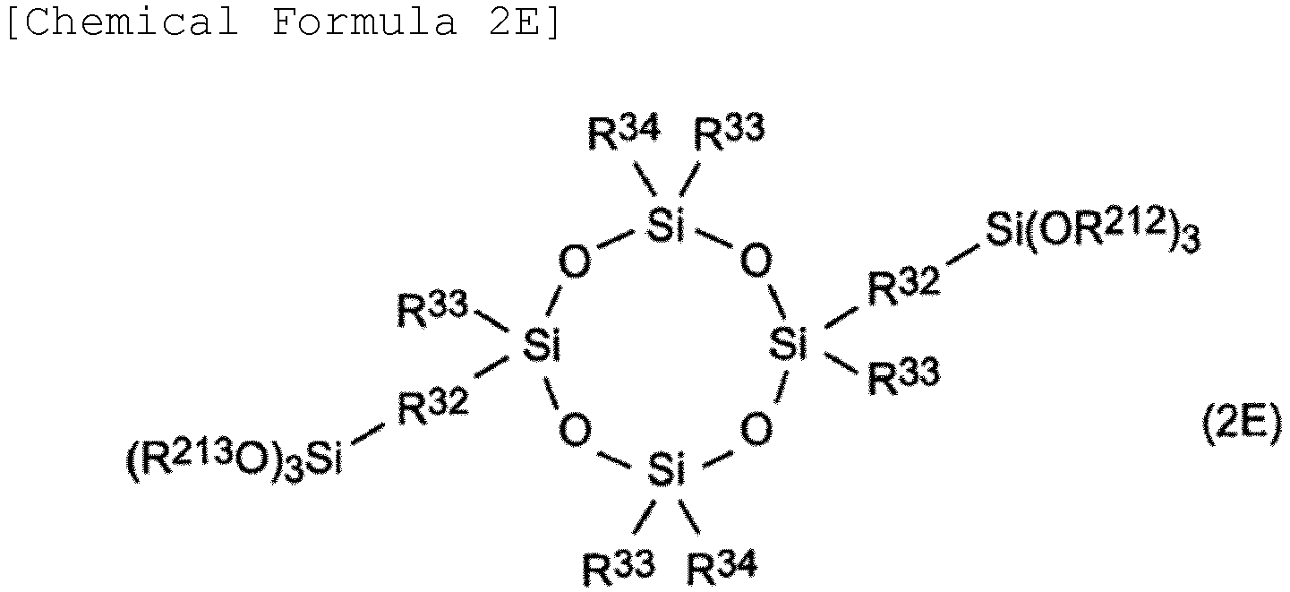 R32 is each independently a divalent hydrocarbon group having 1 to 20 carbon atoms;R33 is each independently a monovalent hydrocarbon group having 1 to 10 carbon atoms;and R34 is each independently a monovalent hydrocarbon group having 1 to 30 carbon atoms;
 wherein R212, R213, and R214 are each independently an alkyl group having 1 to 10 carbon atoms; andR32 is each independently a divalent hydrocarbon group having 1 to 20 carbon atoms.
 - The negative electrode active material according to any one of claims 1 to 4, wherein the film comprises 10% by mass or more and 95% by mass or less of the first metal alkoxide and 5% by mass or more and 90% by mass or less of the second metal alkoxide with respect to a total amount of the film.
- The negative electrode active material according to any one of claims 1 to 5, wherein a content of the film is 0.20% by mass or more and 4.00% by mass or less with respect to a total amount of the negative electrode active material.
- The negative electrode active material according to any one of claims 1 to 6, wherein the negative electrode active material core material comprises at least Si.
- The negative electrode active material according to any one of claims 1 to 7, wherein the battery is a lithium ion secondary battery.
- A negative electrode, comprising:a negative electrode layer including the negative electrode active material according to any one of claims 1 to 8; anda negative electrode current collector.
- A secondary battery, comprising:the negative electrode according to claim 9;a positive electrode;a separator disposed between the positive electrode and the negative electrode; andan electrolyte that are enclosed in an exterior body.
- The secondary battery according to claim 10, wherein the electrolyte is a nonaqueous electrolyte.
- The secondary battery according to claim 10 or 11, wherein the positive electrode and the negative electrode are electrodes capable of occluding and releasing lithium ions.
- A method of producing the negative electrode active material according to any one of claims 1 to 8, the method comprising stirring a negative electrode active material core material together with a first metal alkoxide and a second metal alkoxide in an alkaline solvent.
Applications Claiming Priority (2)
| Application Number | Priority Date | Filing Date | Title |
|---|---|---|---|
| JP2019191389 | 2019-10-18 | ||
| PCT/JP2020/039113 WO2021075554A1 (en) | 2019-10-18 | 2020-10-16 | Negative electrode active material, negative electrode, and secondary battery |
Publications (2)
| Publication Number | Publication Date |
|---|---|
| EP4047684A1 true EP4047684A1 (en) | 2022-08-24 |
| EP4047684A4 EP4047684A4 (en) | 2024-01-03 |
Family
ID=75538120
Family Applications (1)
| Application Number | Title | Priority Date | Filing Date |
|---|---|---|---|
| EP20875725.2A Pending EP4047684A4 (en) | 2019-10-18 | 2020-10-16 | Negative electrode active material, negative electrode, and secondary battery |
Country Status (5)
| Country | Link |
|---|---|
| US (1) | US20220246930A1 (en) |
| EP (1) | EP4047684A4 (en) |
| JP (1) | JP7435617B2 (en) |
| CN (1) | CN114503311B (en) |
| WO (1) | WO2021075554A1 (en) |
Families Citing this family (1)
| Publication number | Priority date | Publication date | Assignee | Title |
|---|---|---|---|---|
| CA3208448A1 (en) * | 2023-08-04 | 2025-06-19 | Hydro-Quebec | Hydrogen sulfide trapping compounds, compositions containing them, and their uses |
Family Cites Families (19)
| Publication number | Priority date | Publication date | Assignee | Title |
|---|---|---|---|---|
| JP3588885B2 (en) * | 1995-12-21 | 2004-11-17 | ソニー株式会社 | Non-aqueous electrolyte battery |
| JP2004335334A (en) | 2003-05-09 | 2004-11-25 | Mitsubishi Materials Corp | Negative electrode material for non-aqueous electrolyte secondary battery, method for producing the same, and non-aqueous electrolyte secondary battery using the same |
| JP4840663B2 (en) | 2006-05-23 | 2011-12-21 | ソニー株式会社 | Negative electrode and battery |
| JP5113393B2 (en) * | 2007-01-22 | 2013-01-09 | パナソニック株式会社 | Negative electrode active material for all solid-state polymer battery, method for producing the same, and all solid-state polymer battery |
| JP4541432B2 (en) * | 2008-07-04 | 2010-09-08 | シャープ株式会社 | Lithium secondary battery |
| CA2638410A1 (en) * | 2008-07-28 | 2010-01-28 | Hydro-Quebec | Composite electrode material |
| JP5536364B2 (en) * | 2009-05-25 | 2014-07-02 | シャープ株式会社 | Negative electrode material for lithium secondary battery and method for producing the same |
| DE102009036945B4 (en) * | 2009-06-30 | 2012-10-11 | Fraunhofer-Gesellschaft zur Förderung der angewandten Forschung e.V. | Particles produced therewith with an organically modified (hetero) silicic acid polycondensate-containing particle containing a metallic core suitable for hydrogen storage, batteries produced therewith and methods for their production using the particles |
| CN101736368B (en) * | 2010-01-13 | 2011-07-20 | 北京科技大学 | Noble metal ceramic composite coating inert anode for aluminum electrolysis and preparation method thereof |
| JP2012169249A (en) | 2011-01-28 | 2012-09-06 | Sanyo Electric Co Ltd | Cathode for nonaqueous electrolyte secondary battery, method for manufacturing the same, and nonaqueous electrolyte secondary battery |
| WO2013014742A1 (en) * | 2011-07-25 | 2013-01-31 | トヨタ自動車株式会社 | Nonaqueous electrolyte secondary battery |
| US20140315086A1 (en) * | 2011-12-14 | 2014-10-23 | Stijn Put | Positively Charged Silicon for Lithium-Ion Batteries |
| CN103700837A (en) * | 2013-12-19 | 2014-04-02 | 湖南兴瑞新材料研究发展有限公司 | Lithium manganate cathode material and preparation method thereof |
| CN105098163B (en) * | 2014-05-16 | 2017-09-29 | 微宏动力系统(湖州)有限公司 | A kind of preparation method of cladded type electrode material |
| CN103996835A (en) * | 2014-06-14 | 2014-08-20 | 哈尔滨工业大学 | Silicon-base negative material with silane coupling agent cladding layer structure as well as preparation method and application of material |
| WO2016007859A1 (en) | 2014-07-11 | 2016-01-14 | Kleermail Corporation | Methods, apparatuses, and systems for facilitating management and/or automation of direct mail campaigns and other bulk/high volume mailings |
| CN108463909B (en) | 2016-01-22 | 2021-03-23 | 杰富意化学株式会社 | Negative electrode material for Li ion secondary battery, method for producing the same, negative electrode for Li ion secondary battery, and Li ion secondary battery |
| JP2017183101A (en) * | 2016-03-30 | 2017-10-05 | 三洋化成工業株式会社 | Coated active material for lithium ion battery and method for manufacturing the same |
| DE102016224032A1 (en) * | 2016-12-02 | 2018-06-07 | Robert Bosch Gmbh | Anode active material particles with artificial SEI layer by means of graft-from-polymerization |
-
2020
- 2020-10-16 JP JP2021552469A patent/JP7435617B2/en active Active
- 2020-10-16 EP EP20875725.2A patent/EP4047684A4/en active Pending
- 2020-10-16 CN CN202080069099.4A patent/CN114503311B/en active Active
- 2020-10-16 WO PCT/JP2020/039113 patent/WO2021075554A1/en not_active Ceased
-
2022
- 2022-04-14 US US17/720,878 patent/US20220246930A1/en active Pending
Also Published As
| Publication number | Publication date |
|---|---|
| WO2021075554A1 (en) | 2021-04-22 |
| JPWO2021075554A1 (en) | 2021-04-22 |
| CN114503311B (en) | 2024-03-01 |
| JP7435617B2 (en) | 2024-02-21 |
| EP4047684A4 (en) | 2024-01-03 |
| CN114503311A (en) | 2022-05-13 |
| US20220246930A1 (en) | 2022-08-04 |
Similar Documents
| Publication | Publication Date | Title |
|---|---|---|
| EP3113273B1 (en) | Lithium ion secondary battery | |
| KR101829528B1 (en) | Electrode, nonaqueous electrolyte battery and battery pack | |
| KR20160110380A (en) | Negative electrode material for nonaqueous electrolyte secondary batteries and method for producing negative electrode active material particles | |
| KR20210130780A (en) | Secondary battery and device including secondary battery | |
| EP2819234B1 (en) | Electrolyte for secondary battery and lithium secondary battery including same | |
| EP2822082B1 (en) | Electrolyte for secondary battery and lithium secondary battery including same | |
| KR102033746B1 (en) | Case for Secondary Battery Comprising Inner Sealant Layer Including Nanaporous Material and Lithium Secondary Battery Comprising the Same | |
| KR20160025052A (en) | Cathode active material for secondary battery and secondary battery comprising the same | |
| US20220158186A1 (en) | Positive electrode active material, positive electrode, and secondary battery | |
| KR20190088217A (en) | Lithium secondary battery | |
| US20240186494A1 (en) | Positive electrode for non-aqueous electrolyte secondary battery and non-aqueous electrolyte secondary battery | |
| EP2983235A1 (en) | Nonaqueous electrolyte secondary battery | |
| EP3859859B1 (en) | Electrolyte for lithium ion secondary battery and lithium ion secondary battery | |
| US20220246930A1 (en) | Negative electrode active material, negative electrode, and secondary battery | |
| KR20240061891A (en) | Lithium secondary battery | |
| KR101515361B1 (en) | Cathode Active Material and Lithium Secondary Battery Comprising The Same | |
| EP4564455A2 (en) | Anode for lithium secondary battery and lithium secondary battery including the same | |
| JP7800652B2 (en) | secondary battery | |
| KR101527539B1 (en) | Cathode Active Material and Lithium Secondary Battery Comprising The Same | |
| WO2023048179A1 (en) | Secondary battery and manufacturing method therefor | |
| WO2023058557A1 (en) | Secondary battery and method for producing same | |
| KR101595328B1 (en) | Anode Electrodes for Secondary Battery and Lithium Secondary Battery Containing The Same | |
| JP5043290B2 (en) | Cathode active material for nonaqueous electrolyte secondary battery, method for producing the same, and nonaqueous electrolyte secondary battery using the same | |
| JP7752656B2 (en) | Nonaqueous electrolyte secondary battery and method of manufacturing the same | |
| JP7765219B2 (en) | Positive electrode for non-aqueous electrolyte secondary battery and non-aqueous electrolyte secondary battery |
Legal Events
| Date | Code | Title | Description |
|---|---|---|---|
| STAA | Information on the status of an ep patent application or granted ep patent |
Free format text: STATUS: THE INTERNATIONAL PUBLICATION HAS BEEN MADE |
|
| PUAI | Public reference made under article 153(3) epc to a published international application that has entered the european phase |
Free format text: ORIGINAL CODE: 0009012 |
|
| STAA | Information on the status of an ep patent application or granted ep patent |
Free format text: STATUS: REQUEST FOR EXAMINATION WAS MADE |
|
| 17P | Request for examination filed |
Effective date: 20220328 |
|
| AK | Designated contracting states |
Kind code of ref document: A1 Designated state(s): AL AT BE BG CH CY CZ DE DK EE ES FI FR GB GR HR HU IE IS IT LI LT LU LV MC MK MT NL NO PL PT RO RS SE SI SK SM TR |
|
| DAV | Request for validation of the european patent (deleted) | ||
| DAX | Request for extension of the european patent (deleted) | ||
| A4 | Supplementary search report drawn up and despatched |
Effective date: 20231205 |
|
| RIC1 | Information provided on ipc code assigned before grant |
Ipc: H01M 4/485 20100101ALI20231129BHEP Ipc: H01M 4/36 20060101AFI20231129BHEP |