EP4047451A1 - Locking input/output module - Google Patents
Locking input/output module Download PDFInfo
- Publication number
- EP4047451A1 EP4047451A1 EP22154272.3A EP22154272A EP4047451A1 EP 4047451 A1 EP4047451 A1 EP 4047451A1 EP 22154272 A EP22154272 A EP 22154272A EP 4047451 A1 EP4047451 A1 EP 4047451A1
- Authority
- EP
- European Patent Office
- Prior art keywords
- actuator
- circuit board
- module
- locking
- support
- Prior art date
- Legal status (The legal status is an assumption and is not a legal conclusion. Google has not performed a legal analysis and makes no representation as to the accuracy of the status listed.)
- Granted
Links
Images




Classifications
-
- G—PHYSICS
- G06—COMPUTING OR CALCULATING; COUNTING
- G06F—ELECTRIC DIGITAL DATA PROCESSING
- G06F1/00—Details not covered by groups G06F3/00 - G06F13/00 and G06F21/00
- G06F1/16—Constructional details or arrangements
- G06F1/18—Packaging or power distribution
- G06F1/183—Internal mounting support structures, e.g. for supporting printed circuit boards
- G06F1/185—Mounting of expansion boards
- G06F1/186—Securing of expansion boards in correspondence to slots provided at the computer enclosure
-
- H—ELECTRICITY
- H05—ELECTRIC TECHNIQUES NOT OTHERWISE PROVIDED FOR
- H05K—PRINTED CIRCUITS; CASINGS OR CONSTRUCTIONAL DETAILS OF ELECTRIC APPARATUS; MANUFACTURE OF ASSEMBLAGES OF ELECTRICAL COMPONENTS
- H05K1/00—Printed circuits
- H05K1/02—Details
- H05K1/14—Structural association of two or more printed circuits
-
- G—PHYSICS
- G05—CONTROLLING; REGULATING
- G05B—CONTROL OR REGULATING SYSTEMS IN GENERAL; FUNCTIONAL ELEMENTS OF SUCH SYSTEMS; MONITORING OR TESTING ARRANGEMENTS FOR SUCH SYSTEMS OR ELEMENTS
- G05B19/00—Program-control systems
- G05B19/02—Program-control systems electric
- G05B19/04—Program control other than numerical control, i.e. in sequence controllers or logic controllers
- G05B19/042—Program control other than numerical control, i.e. in sequence controllers or logic controllers using digital processors
- G05B19/0423—Input/output
-
- H—ELECTRICITY
- H05—ELECTRIC TECHNIQUES NOT OTHERWISE PROVIDED FOR
- H05K—PRINTED CIRCUITS; CASINGS OR CONSTRUCTIONAL DETAILS OF ELECTRIC APPARATUS; MANUFACTURE OF ASSEMBLAGES OF ELECTRICAL COMPONENTS
- H05K5/00—Casings, cabinets or drawers for electric apparatus
- H05K5/02—Details
- H05K5/0217—Mechanical details of casings
- H05K5/0221—Locks; Latches
-
- H—ELECTRICITY
- H05—ELECTRIC TECHNIQUES NOT OTHERWISE PROVIDED FOR
- H05K—PRINTED CIRCUITS; CASINGS OR CONSTRUCTIONAL DETAILS OF ELECTRIC APPARATUS; MANUFACTURE OF ASSEMBLAGES OF ELECTRICAL COMPONENTS
- H05K5/00—Casings, cabinets or drawers for electric apparatus
- H05K5/02—Details
- H05K5/0256—Details of interchangeable modules or receptacles therefor, e.g. cartridge mechanisms
- H05K5/026—Details of interchangeable modules or receptacles therefor, e.g. cartridge mechanisms having standardized interfaces
-
- H—ELECTRICITY
- H05—ELECTRIC TECHNIQUES NOT OTHERWISE PROVIDED FOR
- H05K—PRINTED CIRCUITS; CASINGS OR CONSTRUCTIONAL DETAILS OF ELECTRIC APPARATUS; MANUFACTURE OF ASSEMBLAGES OF ELECTRICAL COMPONENTS
- H05K7/00—Constructional details common to different types of electric apparatus
- H05K7/14—Mounting supporting structure in casing or on frame or rack
- H05K7/1462—Mounting supporting structure in casing or on frame or rack for programmable logic controllers [PLC] for automation or industrial process control
- H05K7/1474—Mounting of modules, e.g. on a base or rail or wall
-
- H—ELECTRICITY
- H05—ELECTRIC TECHNIQUES NOT OTHERWISE PROVIDED FOR
- H05K—PRINTED CIRCUITS; CASINGS OR CONSTRUCTIONAL DETAILS OF ELECTRIC APPARATUS; MANUFACTURE OF ASSEMBLAGES OF ELECTRICAL COMPONENTS
- H05K2201/00—Indexing scheme relating to printed circuits covered by H05K1/00
- H05K2201/10—Details of components or other objects attached to or integrated in a printed circuit board
- H05K2201/10431—Details of mounted components
- H05K2201/10507—Involving several components
- H05K2201/1053—Mounted components directly electrically connected to each other, i.e. not via the PCB
Definitions
- inventions disclosed herein relate to the field of automation control systems, such as those used in industrial and commercial settings. More particularly, embodiments of the present invention relate to techniques for providing, accessing, configuring, operating, or interfacing with input/output (I/O) devices that are configured for coupling and interaction with an automation controller.
- I/O input/output
- Automation controllers arc special purpose computers used for controlling industrial automation and the like. Under the direction of stored programs, a processor of the automation controller examines a series of inputs (e.g., electrical input signals to the automation controller) reflecting the status of a controlled process and changes outputs (e.g., electrical output signals from the automation controller) based on analysis and logic for affecting control of the controlled process.
- the stored control programs may be continuously executed in a series of execution cycles, executed periodically, or executed based on events.
- the inputs received by the automation controller from the controlled process and the outputs transmitted by the automation controller to the controlled process arc normally passed through one or more I/O devices, which are components of an automation control system that serve as an electrical interface between the automation controller and the controlled process.
- Traditional I/O devices typically include a base configured to couple the I/O device with a bus bar, communication bus, or the like, a terminal block for communicatively coupling the I/O device with field devices, and an I/O module that includes circuitry for performing communication functions and/or logic operations.
- the I/O module may be coupled to the base by pushing the module toward the base. Friction or a simple locking mechanism between parts of the I/O module and the base may help prevent the I/O module from disengaging from the base.
- locking toggle mechanisms have been employed to secure an I/O module to a base. In other arrangements, screws or other fasteners are used to secure an I/O module to a base.
- the I/O module may be removed from the base by pulling the I/O module away from the base.
- an I/O system comprises an I/O base having a first connector component, an I/O module selectively attachable to the I/O base and having a second connector component adapted to mate with the first connector component, and a locking actuator assembly for securing the I/O module to the I/O base.
- the locking actuator assembly includes an actuator supported for axial and rotational movement by the I/O module, the actuator movable from an unlocked position having a first end of the actuator extending from a housing of the I/O module to a locked position wherein a second end of the actuator extends from the housing, the second end of the actuator including at least one flange adapted to pass through a corresponding slot/opening in a surface of the I/O base such that when the actuator is rotated the at least one flange restricts withdrawal of the actuator from the slot/opening in the I/O base.
- the second connector component can be supported by a circuit board within the housing, and the actuator can be supported by a bracket secured to the circuit board adjacent the second connector component.
- the bracket can include a support having first and second ends secured to the circuit board at outboard locations of the circuit board such that a major portion of a width of the circuit board is bridged by the support.
- the support can include a cylindrical portion between its first and second ends through which the actuator extends.
- the assembly can further include a cap secured to the support, the cylindrical portion of the support and the cap defining a cavity in which at least one radially extending guide flange of the actuator is received.
- the cap and the cylindrical portion can define at least one slot in which the at least one guide flange is received, the at least one slot delimiting axial and rotational movement of the actuator.
- the at least one slot can be L-shape, having a first portion of the L-shape extending axially and a second portion of the L-shape extending circumferentially.
- a biasing element can be interposed between the at least one guide flange and the cylindrical portion of the support, the biasing element urging the actuator axially towards to unlocked position.
- the first end of the actuator can extend from a first exterior side of the housing of the I/O device when in the unlocked position, and wherein the second end of the actuator extends from a second exterior side of the housing opposite the first exterior side when in the locked position.
- the support can be secured to the circuit board adjacent the second exterior side of the housing.
- the circuit board can support a first connector component adapted to mate with a second connector component of the associated second device, and the actuator can be supported by a bracket secured to the circuit board adjacent the connector component.
- the actuator can be supported by the support at a location between first and second ends of the support, the first and second ends of the support being secured to the circuit board at outboard locations thereof such that a major portion of a width of the circuit board is bridged by the support.
- a cylindrical portion of the bracket and a cap secured to the bracket define a cavity in which a radially extending guide flange of the actuator is received.
- the cap and the cylindrical portion define at least one slot in which the at least one radially extending guide flange is received, the at least one slot delimiting axial and rotational movement of the actuator.
- the at least one slot can be L-shape having a first portion of the L-shape extending axially and a second portion of the L-shape extending circumferentially.
- a biasing element can be interposed between the at least one guide flange and the cylindrical portion of the support, the biasing element urging the actuator axially towards to unlocked position.
- the bracket can be secured to the circuit board adjacent an edge thereof, and the actuator can be coextensive with the circuit board in a direction perpendicular to the bracket.
- a method of securing a first device of an I/O system to a second device of an I/O system comprises coupling the first device to the second device, and locking the first device to the second device with a locking actuator assembly.
- the locking actuator assembly includes an actuator supported for axial and rotational movement by a circuit board of the first device, the actuator movable from an unlocked position to a locked position upon axial depression and rotation of a first end of the actuator, wherein a second end of the actuator includes at least one flange adapted to pass through a corresponding slot in a surface of the second device such that when the actuator is rotated the at least one flange restricts withdrawal of the actuator from the slot/opening in the surface of the second device.
- Locking the first device to the second device can include depressing and rotating the first end of the actuator from an external side of the first device opposite the second device.
- FIGURE 1 is a diagrammatical representation of a control and monitoring system adapted to interface with networked components and configuration equipment in accordance with embodiments of the present techniques.
- a full description of the system is set forth in commonly-assigned U.S. Pat. No 9,059,539, issue on June 16, 2015 , which is hereby incorporated herein by reference in its entirety.
- control and monitoring system is generally indicated by reference numeral 10.
- control and monitoring system 10 is illustrated as including a human machine interface (HMI) 12 and an automation controller or control/monitoring device 14 adapted to interface with components of a process 16.
- HMI human machine interface
- automation controller or control/monitoring device 14 adapted to interface with components of a process 16.
- the illustrated process 16 includes sensors 18 and actuators 20.
- the sensors 18 can include any number of devices adapted to provide information regarding process conditions.
- the actuators 20 can include any number of devices adapted to perform a mechanical action in response to a signal from a controller (e.g., an automation controller).
- the sensors 18 and actuators 20 can be utilized to operate process equipment. Indeed, they can be utilized within process loops that are monitored and controlled by the control/monitoring device 14 and/or the HMI 12. Such a process loop can be activated based on process inputs (e.g., input from a sensor 18) or direct operator input received through the HMI 12.
- the sensors 18 and actuators 20 are in communication with the control/monitoring device 14 and may be assigned a particular address in the control/monitoring device 14 that is accessible by the HMI 12. As illustrated, the sensors 18 and actuators 20 can communicate with the control/monitoring device 14 via one or more I/O devices 22 coupled to the control/monitoring device 14. The I/O devices 22 can transfer input and output signals between the control/monitoring device 14 and the controlled process 16. The I/O devices 22 can be integrated with the control/monitoring device 14, or can be added or removed via expansion slots, bays or other suitable mechanisms. For example, additional I/O devices 22 can be added to add functionality to the control/monitoring device 14.
- the I/O devices 22 can include input modules that receive signals from input devices such as photo-sensors and proximity switches, output modules that use output signals to energize relays or to start motors, and bidirectional I/O modules, such as motion control modules which can direct motion devices and receive position or speed feedback.
- the I/O devices 22 can convert between AC and DC analog signals used by devices on a controlled machine or process and DC logic signals used by the control/monitoring device 14.
- FIGURE 2 is a perspective view of a plurality of I/O devices 22 connected to an I/O adapter 24 in accordance with embodiments of the present techniques.
- the I/O adapter 24 is configured to provide system power to the I/O modules 22, as well as to enable conversion between the communications protocols of the I/O devices 22 and the control/monitoring device 14.
- the I/O adapter 24 and the plurality of I/O devices 22 are mounted to a DIN rail 26, which is an industry standard support rail for mounting control equipment in racks and cabinets.
- the plurality of I/O devices 22 are electrically coupled in series along the DIN rail 26 such that field power and system information and power may be communicated between the I/O devices 22, and back through the I/O adapter 24 to the control/monitoring device 14.
- Each of the I/O devices 22 includes a base 28 for physically and communicatively connecting the I/O device 22 to the DIN rail 26, the I/O adapter 24 and/or adjacent I/O devices 22, a terminal block 30, and one or more I/O modules 32.
- the terminal block 30 may be used to electrically connect the I/O device 22 to field devices, such as the sensors 18 and actuators 20 illustrated in FIGURE 1 . In certain arrangements, the terminal block 30 can be removable from the base 28.
- the I/O modules 32 may include I/O control circuitry and/or logic.
- the I/O modules 32 receive input signals from the field devices, deliver output signals to the field devices, perform general and/or specific local functionality on the inputs and/or outputs, communicate the inputs and/or outputs to the control/monitoring device 14 and/or the other I/O devices 22, and so forth.
- an exemplary I/O system is illustrated and identified generally by reference numeral 10'.
- the I/O system 10' generally includes many of the same components, features and functionality of the I/O system 10 shown and described in connection with FIGURES 1 and 2 .
- These components include, generally, an I/O base 24' mountable to a DIN rail (not shown) and having a base circuit board 38 with a plurality of connectors C1, a plurality of I/O devices 22' each including an I/O module 32' mounted to the base 24' and a terminal block 30'.
- Each I/O module 32' includes a connector C2 adapted for mating with a respective connector C1 of the I/O base 24'.
- each I/O module 32' includes a locking actuator assembly 40 for securing the I/O module 32' to the base 24'.
- the locking actuator assembly 40 generally includes a spring-loaded actuator 42 supported for rotational and reciprocating movement within a housing 44 of the I/O module 32' by a collar C and a bracket 46.
- Collar C in the illustrated embodiment is supported in an LED circuit board 50 of the I/O module 32'.
- Bracket 46 is secured to a main circuit board 52 of the I/O module 32' adjacent connector component C2 of the I/O module 32'.
- the actuator 40 is movable from a first, unlocked position, shown in FIGURE 4 to a second, locked position shown in FIGURE 5 .
- a first end 60 of the actuator 42 includes a slot 62 for engagement with a tool, such as a screwdriver, for depressing and rotating the actuator 42. It will be appreciated that other arrangements for facilitating depression and rotation of the actuator 42 can be employed without departing from the scope of the present disclosure, such as hex or torx arrangements, knobs etc.
- An opposite end 66 of the actuator 42 includes radially outwardly extending flanges F giving the actuator 42 a T-shape cross-section. The end 66 of the actuator 42 protrudes beyond the housing 44 when the actuator 42 is in the locked position, as best seen in FIGURE 5 .
- the locking actuator assembly 40 is shown isolated from the housing 44 of the I/O module 32'.
- the collar C is received in a slot in the LED circuit board 50 and supports the actuator 42 for rotational and reciprocating movement at a location adjacent the first end 60 of the actuator 42.
- the bracket 46 includes a longitudinally extending support 70 secured to the main circuit board 52 with fasteners 72. such as pins, screws, adhesive etc., at outboard locations of the main circuit board 42 immediately adjacent a lower terminal edge of the circuit board 52.
- the bracket 46 is not attached to the circuit board 52 between the fasteners 72 thereby maintaining a major portion of the circuit board 52 available for surface mount components and the like.
- the bracket 46 spans a majot portion of the circuit board 52 between the fasteners 72.
- the bracket 46 includes a barrel portion 76 through which the second end 66 of the actuator 42 extends.
- the barrel portion 76 includes opposite axially extending arms A that extend from the support 70 and a cylindrical portion 78 extending from the arms A.
- the actuator 42 includes radially extending flanges 82.
- the radially extending flanges 82 extend in opposite radial directions and are received in respective L-shape slots 92 formed by portions of the arms A, the cylindrical portion 78 and a cap 94 that is secured to the bracket support 70.
- the L-shape slots 92 have an axially extending portion AE and a circumferentially extending portion CE.
- the axially extending portion corresponds to the base horizontal portion of the L-shape while the circumferentially extending portion corresponds to the vertical portion of the L-shape.
- Flanges 82 of the actuator 42 are captured between the barrel portion 76 of the bracket 46 and the cap 94, and a biasing element in the form of a coil spring S (see FIGURE 3B ) biases the actuator 42 upwardly towards the unlocked position.
- the spring S is received in the cylindrical portion 78 of the barrel portion 76 and urges the flanges 82 of the actuator 42 upwardly.
- the flanges 82 being received in the L-shape slots 92 of the bracket 46, restrict both reciprocating and rotational movement of the actuator 42.
- the actuator 42 is shown depressed against the biasing force of the spring S. Further depression of the actuator 42 is restricted by the flanges 82 impinging on a circumferential end wall of the cylindrical portion 78 of the barrel portion 76. Counterclockwise rotation of the actuator 42 is also restricted by the flanges 82 impinging on the arms A.
- the actuator 42 is free to travel upwardly in FIGURE 7 to an undepressed position, corresponding to an unlocked position, limited by impingement of the flanges 82 on a circumferential end face of the cap 94, and free to rotate clockwise to the left in FIGURE 7 to a locked position.
- the flanges 82 are trapped in the circumferentially extending portion CE of the slots 92 and thereby the actuator 42 is restricted from axial movement.
- the I/O module 32' can be secured to the base 24' after engagement of the connector component C2 of the I/O module 32' with the connector component C1 of the base 24' by depressing end 60 of the actuator and then rotating the actuator clockwise 90 degrees.
- the flanges F of the end 62 of the actuator are aligned with a correspondingly-shaped opening O in the circuit board 38 of the base 24'.
- the flanges F of the end 66 of the actuator 42 pass through the opening O to a position below the circuit board 38. Rotation of the actuator 42 ninety degrees results in the flanges F no longer being aligned with the opening O in the circuit board 38. Accordingly, as the spring urges the actuator 42 upwardly, the flanges F engage an opposite side of the circuit board 38 surrounding the opening O.
- the spring force of the spring S holds the I/O module 32' and, more directly, the circuit board 52 of the I/O module 32', against the circuit board 38 base 24'.
- springs having various spring constants can be employed to apply a wide range of holding forces.
- the spring S can be omitted.
- the spring-loaded actuator is desirable for accommodating tolerance stack-up in the various components of the I/O system and/or the locking actuator assembly 40.
- the locking actuator assembly 40 of the present disclosure locates the interlocking features (e.g., flanges F and opening O) in close proximity to the connector components C1 and C2 of the I/O module 32' and base 24'. This results in a more compact force path between the interlocked components.
- the actuator 42 engages the circuit board 38 of the base 24' in close proximity to the attachment points/fasteners 72 of the support 46 to the main circuit board 52. As such, a major portion of the actuator 42 is not under load in the locked position, the forces instead being transferred from the flanges F to the flanges 82 through spring S to barrel portion 78 and to the main circuit board 52 via the support 46.
- the actuator 42 remains conveniently accessible from an outer surface of the I/O module 32', and also provides a visual indication of the status (e.g., locked or unlocked) of the locking actuator assembly (e.g., the actuator end 60 is proud of the housing 46 when unlocked, and flush with the housing 46 when locked).
- the circuit boards 38 and 52 in close proximity to the connector pair achieves a more reliable connection between the connector pairs, and eliminates any tolerance stack-up that would result from interlocking, for example, the housings of an I/O module and I/O base.
- the L-shape slots 92 limit the travel of the actuator 42 axially and rotationally.
- actuator point of failure can be designed into the actuator 42 for situations where excessive force is applied to the actuator 42.
- Such points of failure include, but are not limited to. the screwdriver slot 62. the flanges 82, and/or the shaft of the actuator 42.
- FIGURES 9 and 10 another exemplary embodiment of an I/O in accordance with the present disclosure is illustrated and identified generally by reference numeral 32 ⁇ .
- two locking actuator assemblies 40" arc provided at opposite corners of the I/O module 24".
- the locking actuator assemblies 40" are similar to the locking actuator assembly 40 of FIGURES 3-8 , with the exception that the support 46 is omitted in the locking actuators 40". Instead, the locking actuator assemblies 40" are mounted directly to the main circuit board 52" via bracket B ⁇ .
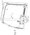
- FIG 11 illustrates another exemplary embodiment of an I/O module 32′′′ in accordance with the present disclosure.
- a locking actuator assembly 40′′′ is fixed directly to a main circuit board 52′′′ via bracket B′′′.
- locking actuator assemblies 40" and 40′′′ are the same as locking actuator assembly 40 described in detail above except for the structure attaching them to the circuit boards.
Landscapes
- Engineering & Computer Science (AREA)
- Microelectronics & Electronic Packaging (AREA)
- Physics & Mathematics (AREA)
- General Physics & Mathematics (AREA)
- Automation & Control Theory (AREA)
- Computer Hardware Design (AREA)
- General Engineering & Computer Science (AREA)
- Theoretical Computer Science (AREA)
- Power Engineering (AREA)
- Human Computer Interaction (AREA)
- Details Of Connecting Devices For Male And Female Coupling (AREA)
- Mounting Of Printed Circuit Boards And The Like (AREA)
Abstract
Description
- The subject matter disclosed herein relates to the field of automation control systems, such as those used in industrial and commercial settings. More particularly, embodiments of the present invention relate to techniques for providing, accessing, configuring, operating, or interfacing with input/output (I/O) devices that are configured for coupling and interaction with an automation controller.
- Automation controllers arc special purpose computers used for controlling industrial automation and the like. Under the direction of stored programs, a processor of the automation controller examines a series of inputs (e.g., electrical input signals to the automation controller) reflecting the status of a controlled process and changes outputs (e.g., electrical output signals from the automation controller) based on analysis and logic for affecting control of the controlled process. The stored control programs may be continuously executed in a series of execution cycles, executed periodically, or executed based on events. The inputs received by the automation controller from the controlled process and the outputs transmitted by the automation controller to the controlled process arc normally passed through one or more I/O devices, which are components of an automation control system that serve as an electrical interface between the automation controller and the controlled process.
- Traditional I/O devices typically include a base configured to couple the I/O device with a bus bar, communication bus, or the like, a terminal block for communicatively coupling the I/O device with field devices, and an I/O module that includes circuitry for performing communication functions and/or logic operations. In traditional automation control systems, the I/O module may be coupled to the base by pushing the module toward the base. Friction or a simple locking mechanism between parts of the I/O module and the base may help prevent the I/O module from disengaging from the base. In the past, locking toggle mechanisms have been employed to secure an I/O module to a base. In other arrangements, screws or other fasteners are used to secure an I/O module to a base. The I/O module may be removed from the base by pulling the I/O module away from the base.
- It is now recognized that it is desirable to provide more efficient and effective techniques for coupling, locking, and uncoupling I/O modules from bases of I/O devices. In accordance with one aspect of the present disclosure, an I/O system comprises an I/O base having a first connector component, an I/O module selectively attachable to the I/O base and having a second connector component adapted to mate with the first connector component, and a locking actuator assembly for securing the I/O module to the I/O base. The locking actuator assembly includes an actuator supported for axial and rotational movement by the I/O module, the actuator movable from an unlocked position having a first end of the actuator extending from a housing of the I/O module to a locked position wherein a second end of the actuator extends from the housing, the second end of the actuator including at least one flange adapted to pass through a corresponding slot/opening in a surface of the I/O base such that when the actuator is rotated the at least one flange restricts withdrawal of the actuator from the slot/opening in the I/O base.
- The second connector component can be supported by a circuit board within the housing, and the actuator can be supported by a bracket secured to the circuit board adjacent the second connector component. The bracket can include a support having first and second ends secured to the circuit board at outboard locations of the circuit board such that a major portion of a width of the circuit board is bridged by the support. The support can include a cylindrical portion between its first and second ends through which the actuator extends. The assembly can further include a cap secured to the support, the cylindrical portion of the support and the cap defining a cavity in which at least one radially extending guide flange of the actuator is received. The cap and the cylindrical portion can define at least one slot in which the at least one guide flange is received, the at least one slot delimiting axial and rotational movement of the actuator. The at least one slot can be L-shape, having a first portion of the L-shape extending axially and a second portion of the L-shape extending circumferentially. A biasing element can be interposed between the at least one guide flange and the cylindrical portion of the support, the biasing element urging the actuator axially towards to unlocked position. The first end of the actuator can extend from a first exterior side of the housing of the I/O device when in the unlocked position, and wherein the second end of the actuator extends from a second exterior side of the housing opposite the first exterior side when in the locked position. The support can be secured to the circuit board adjacent the second exterior side of the housing.
- In accordance with another aspect, a locking actuator assembly for selectively securing together associated first and second devices of an associated I/O system comprises a locking actuator assembly including an actuator supported for axial and rotational movement by a circuit board of the associated first device, the actuator movable from an unlocked position to a locked position upon axial depression and rotation of a first end of the actuator, wherein a second end of the actuator includes at least one flange adapted to pass through a corresponding slot/opening in a surface of the associated second device such that when the actuator is rotated the at least one flange restricts withdrawal of the actuator from the slot/opening in the surface of the associated second device.
- The circuit board can support a first connector component adapted to mate with a second connector component of the associated second device, and the actuator can be supported by a bracket secured to the circuit board adjacent the connector component. The actuator can be supported by the support at a location between first and second ends of the support, the first and second ends of the support being secured to the circuit board at outboard locations thereof such that a major portion of a width of the circuit board is bridged by the support. A cylindrical portion of the bracket and a cap secured to the bracket define a cavity in which a radially extending guide flange of the actuator is received. The cap and the cylindrical portion define at least one slot in which the at least one radially extending guide flange is received, the at least one slot delimiting axial and rotational movement of the actuator. The at least one slot can be L-shape having a first portion of the L-shape extending axially and a second portion of the L-shape extending circumferentially. A biasing element can be interposed between the at least one guide flange and the cylindrical portion of the support, the biasing element urging the actuator axially towards to unlocked position. The bracket can be secured to the circuit board adjacent an edge thereof, and the actuator can be coextensive with the circuit board in a direction perpendicular to the bracket.
- In accordance with another aspect, a method of securing a first device of an I/O system to a second device of an I/O system comprises coupling the first device to the second device, and locking the first device to the second device with a locking actuator assembly. The locking actuator assembly includes an actuator supported for axial and rotational movement by a circuit board of the first device, the actuator movable from an unlocked position to a locked position upon axial depression and rotation of a first end of the actuator, wherein a second end of the actuator includes at least one flange adapted to pass through a corresponding slot in a surface of the second device such that when the actuator is rotated the at least one flange restricts withdrawal of the actuator from the slot/opening in the surface of the second device. Locking the first device to the second device can include depressing and rotating the first end of the actuator from an external side of the first device opposite the second device.
-
-
FIGURE 1 is a diagrammatical representation of an exemplary control and monitoring system adapted to interface with networked components and configuration equipment; -
FIGURE 2 is a perspective view of a plurality of I/O devices connected to an I/O adapter; -
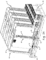
FIGURE 3A is a perspective cross-sectional view of a plurality of I/O modules connected to an I/O base; -
FIGURE 3B is an enlarged perspective view of a locking actuator assembly of an I/O module in a locked configuration; -
FIGURE 4 is a cutaway view of an exemplary I/O module with a locking actuator assembly in an unlocked state; -
FIGURE 5 is a cutaway view of an exemplary I/O module with a locking actuator assembly in a locked state; -
FIGURE 6 is a perspective view of a circuit board of an exemplary I/O module including a locking actuator assembly; -
FIGURE 7 is a perspective view of an exemplary locking actuator assembly in accordance with the present disclosure; -
FIGURE 8 is a perspective view of an actuator of a locking actuator assembly in accordance with the present disclosure; -
FIGURE 9 is a cutaway perspective view of an exemplary I/O module having first and second locking actuator assemblies in accordance with the present disclosure; -
FIGURE 10 is another cutaway perspective view of the I/O module ofFIGURE 9 ; and -
FIGURE 11 is a cutaway perspective view of another exemplary I/O module having a locking actuator assembly in accordance with the present disclosure. -
FIGURE 1 is a diagrammatical representation of a control and monitoring system adapted to interface with networked components and configuration equipment in accordance with embodiments of the present techniques. A full description of the system is set forth in commonly-assignedU.S. Pat. No 9,059,539, issue on June 16, 2015 - The control and monitoring system is generally indicated by
reference numeral 10. Specifically, the control andmonitoring system 10 is illustrated as including a human machine interface (HMI) 12 and an automation controller or control/monitoring device 14 adapted to interface with components of aprocess 16. - The illustrated
process 16 includessensors 18 andactuators 20. Thesensors 18 can include any number of devices adapted to provide information regarding process conditions. Theactuators 20 can include any number of devices adapted to perform a mechanical action in response to a signal from a controller (e.g., an automation controller). Thesensors 18 andactuators 20 can be utilized to operate process equipment. Indeed, they can be utilized within process loops that are monitored and controlled by the control/monitoring device 14 and/or theHMI 12. Such a process loop can be activated based on process inputs (e.g., input from a sensor 18) or direct operator input received through theHMI 12. - As illustrated, the
sensors 18 andactuators 20 are in communication with the control/monitoring device 14 and may be assigned a particular address in the control/monitoring device 14 that is accessible by theHMI 12. As illustrated, thesensors 18 andactuators 20 can communicate with the control/monitoring device 14 via one or more I/O devices 22 coupled to the control/monitoring device 14. The I/O devices 22 can transfer input and output signals between the control/monitoring device 14 and the controlledprocess 16. The I/O devices 22 can be integrated with the control/monitoring device 14, or can be added or removed via expansion slots, bays or other suitable mechanisms. For example, additional I/O devices 22 can be added to add functionality to the control/monitoring device 14. - The I/
O devices 22 can include input modules that receive signals from input devices such as photo-sensors and proximity switches, output modules that use output signals to energize relays or to start motors, and bidirectional I/O modules, such as motion control modules which can direct motion devices and receive position or speed feedback. In some arrangements, the I/O devices 22 can convert between AC and DC analog signals used by devices on a controlled machine or process and DC logic signals used by the control/monitoring device 14. -
FIGURE 2 is a perspective view of a plurality of I/O devices 22 connected to an I/O adapter 24 in accordance with embodiments of the present techniques. The I/O adapter 24 is configured to provide system power to the I/O modules 22, as well as to enable conversion between the communications protocols of the I/O devices 22 and the control/monitoring device 14. As illustrated, the I/O adapter 24 and the plurality of I/O devices 22 are mounted to aDIN rail 26, which is an industry standard support rail for mounting control equipment in racks and cabinets. The plurality of I/O devices 22 are electrically coupled in series along theDIN rail 26 such that field power and system information and power may be communicated between the I/O devices 22, and back through the I/O adapter 24 to the control/monitoring device 14. - Each of the I/
O devices 22 includes abase 28 for physically and communicatively connecting the I/O device 22 to theDIN rail 26, the I/O adapter 24 and/or adjacent I/O devices 22, aterminal block 30, and one or more I/O modules 32. Theterminal block 30 may be used to electrically connect the I/O device 22 to field devices, such as thesensors 18 andactuators 20 illustrated inFIGURE 1 . In certain arrangements, theterminal block 30 can be removable from thebase 28. The I/O modules 32 may include I/O control circuitry and/or logic. In general, the I/O modules 32 receive input signals from the field devices, deliver output signals to the field devices, perform general and/or specific local functionality on the inputs and/or outputs, communicate the inputs and/or outputs to the control/monitoring device 14 and/or the other I/O devices 22, and so forth. - With reference to
FIGURE 3A and3B , an exemplary I/O system is illustrated and identified generally by reference numeral 10'. It should be appreciated that the I/O system 10' generally includes many of the same components, features and functionality of the I/O system 10 shown and described in connection withFIGURES 1 and2 . These components include, generally, an I/O base 24' mountable to a DIN rail (not shown) and having abase circuit board 38 with a plurality of connectors C1, a plurality of I/O devices 22' each including an I/O module 32' mounted to the base 24' and a terminal block 30'. Each I/O module 32' includes a connector C2 adapted for mating with a respective connector C1 of the I/O base 24'. - In accordance with the present disclosure, each I/O module 32' includes a locking
actuator assembly 40 for securing the I/O module 32' to the base 24'. With additional reference toFIGURES 4 and 5 , the lockingactuator assembly 40 generally includes a spring-loadedactuator 42 supported for rotational and reciprocating movement within ahousing 44 of the I/O module 32' by a collar C and abracket 46. Collar C in the illustrated embodiment is supported in anLED circuit board 50 of the I/O module 32'.Bracket 46 is secured to amain circuit board 52 of the I/O module 32' adjacent connector component C2 of the I/O module 32'. Theactuator 40 is movable from a first, unlocked position, shown inFIGURE 4 to a second, locked position shown inFIGURE 5 . - A
first end 60 of theactuator 42 includes aslot 62 for engagement with a tool, such as a screwdriver, for depressing and rotating theactuator 42. It will be appreciated that other arrangements for facilitating depression and rotation of theactuator 42 can be employed without departing from the scope of the present disclosure, such as hex or torx arrangements, knobs etc. Anopposite end 66 of theactuator 42 includes radially outwardly extending flanges F giving the actuator 42 a T-shape cross-section. Theend 66 of theactuator 42 protrudes beyond thehousing 44 when theactuator 42 is in the locked position, as best seen inFIGURE 5 . - Turning to
FIGURE 6 , the lockingactuator assembly 40 is shown isolated from thehousing 44 of the I/O module 32'. The collar C is received in a slot in theLED circuit board 50 and supports theactuator 42 for rotational and reciprocating movement at a location adjacent thefirst end 60 of theactuator 42. Thebracket 46 includes alongitudinally extending support 70 secured to themain circuit board 52 withfasteners 72. such as pins, screws, adhesive etc., at outboard locations of themain circuit board 42 immediately adjacent a lower terminal edge of thecircuit board 52. In the illustrated embodiment, thebracket 46 is not attached to thecircuit board 52 between thefasteners 72 thereby maintaining a major portion of thecircuit board 52 available for surface mount components and the like. Thebracket 46 spans a majot portion of thecircuit board 52 between thefasteners 72. - With additional reference to
FIGURES 7 and 8 . thebracket 46 includes abarrel portion 76 through which thesecond end 66 of theactuator 42 extends. Thebarrel portion 76 includes opposite axially extending arms A that extend from thesupport 70 and acylindrical portion 78 extending from the arms A. - As best seen in
FIGURE 8 , theactuator 42 includes radially extendingflanges 82. Theradially extending flanges 82 extend in opposite radial directions and are received in respective L-shape slots 92 formed by portions of the arms A, thecylindrical portion 78 and acap 94 that is secured to thebracket support 70. The L-shape slots 92 have an axially extending portion AE and a circumferentially extending portion CE. In the illustrated embodiment, the axially extending portion corresponds to the base horizontal portion of the L-shape while the circumferentially extending portion corresponds to the vertical portion of the L-shape. -
Flanges 82 of theactuator 42 are captured between thebarrel portion 76 of thebracket 46 and thecap 94, and a biasing element in the form of a coil spring S (seeFIGURE 3B ) biases theactuator 42 upwardly towards the unlocked position. The spring S is received in thecylindrical portion 78 of thebarrel portion 76 and urges theflanges 82 of theactuator 42 upwardly. - It should be appreciated that the
flanges 82, being received in the L-shape slots 92 of thebracket 46, restrict both reciprocating and rotational movement of theactuator 42. InFIGURE 7 , theactuator 42 is shown depressed against the biasing force of the spring S. Further depression of theactuator 42 is restricted by theflanges 82 impinging on a circumferential end wall of thecylindrical portion 78 of thebarrel portion 76. Counterclockwise rotation of theactuator 42 is also restricted by theflanges 82 impinging on the arms A. From the position illustrated inFIGURE 7 , theactuator 42 is free to travel upwardly inFIGURE 7 to an undepressed position, corresponding to an unlocked position, limited by impingement of theflanges 82 on a circumferential end face of thecap 94, and free to rotate clockwise to the left inFIGURE 7 to a locked position. When rotated to the locked position, theflanges 82 are trapped in the circumferentially extending portion CE of theslots 92 and thereby theactuator 42 is restricted from axial movement. - It will now be appreciated that the I/O module 32' can be secured to the base 24' after engagement of the connector component C2 of the I/O module 32' with the connector component C1 of the base 24' by depressing
end 60 of the actuator and then rotating the actuator clockwise 90 degrees. - Returning to
FIGURE 3B , when theactuator 42 is in the unlocked position, the flanges F of theend 62 of the actuator are aligned with a correspondingly-shaped opening O in thecircuit board 38 of the base 24'. When theactuator 42 is depressed, the flanges F of theend 66 of theactuator 42 pass through the opening O to a position below thecircuit board 38. Rotation of the actuator 42 ninety degrees results in the flanges F no longer being aligned with the opening O in thecircuit board 38. Accordingly, as the spring urges theactuator 42 upwardly, the flanges F engage an opposite side of thecircuit board 38 surrounding the opening O. Thus, the spring force of the spring S holds the I/O module 32' and, more directly, thecircuit board 52 of the I/O module 32', against thecircuit board 38 base 24'. - It should be appreciated that springs having various spring constants can be employed to apply a wide range of holding forces. In some embodiments, the spring S can be omitted. In many applications, however, the spring-loaded actuator is desirable for accommodating tolerance stack-up in the various components of the I/O system and/or the locking
actuator assembly 40. - It should also be appreciated that the locking
actuator assembly 40 of the present disclosure locates the interlocking features (e.g., flanges F and opening O) in close proximity to the connector components C1 and C2 of the I/O module 32' and base 24'. This results in a more compact force path between the interlocked components. For example, theactuator 42 engages thecircuit board 38 of the base 24' in close proximity to the attachment points/fasteners 72 of thesupport 46 to themain circuit board 52. As such, a major portion of theactuator 42 is not under load in the locked position, the forces instead being transferred from the flanges F to theflanges 82 through spring S tobarrel portion 78 and to themain circuit board 52 via thesupport 46. However, theactuator 42 remains conveniently accessible from an outer surface of the I/O module 32', and also provides a visual indication of the status (e.g., locked or unlocked) of the locking actuator assembly (e.g., theactuator end 60 is proud of thehousing 46 when unlocked, and flush with thehousing 46 when locked). Interlocking thecircuit boards - As shown best in
FIGURE 8 . the L-shape slots 92 limit the travel of theactuator 42 axially and rotationally. As such, actuator point of failure can be designed into theactuator 42 for situations where excessive force is applied to theactuator 42. Such points of failure include, but are not limited to. thescrewdriver slot 62. theflanges 82, and/or the shaft of theactuator 42. - Turning to
FIGURES 9 and 10 , another exemplary embodiment of an I/O in accordance with the present disclosure is illustrated and identified generally by reference numeral 32ʺ. In this embodiment, two lockingactuator assemblies 40" arc provided at opposite corners of the I/O module 24". The lockingactuator assemblies 40" are similar to the lockingactuator assembly 40 ofFIGURES 3-8 , with the exception that thesupport 46 is omitted in the lockingactuators 40". Instead, the lockingactuator assemblies 40" are mounted directly to themain circuit board 52" via bracket Bʺ. -
Figure 11 illustrates another exemplary embodiment of an I/O module 32‴ in accordance with the present disclosure. In this example, a lockingactuator assembly 40‴ is fixed directly to amain circuit board 52‴ via bracket B‴. - It should be appreciated that the form and function of the locking
actuator assemblies 40" and 40‴ are the same as lockingactuator assembly 40 described in detail above except for the structure attaching them to the circuit boards. - In the preceding specification, various embodiments have been described with reference to the accompanying drawings. It will, however, be evident that various modifications and changes may be made thereto, and additional embodiments may be implemented, without departing from the broader scope of the invention as set forth in the claims that follow. The specification and drawings are accordingly to be regarded in an illustrative rather than restrictive sense.
-
- Embodiment 1: An I/O system comprising:
- an I/O base having a first connector component;
- an I/O module selectively attachable to the I/O base and having a second connector component adapted to mate with the first connector component; and
- a locking actuator assembly for securing the I/O module to the I/O base;
- wherein the locking actuator assembly includes an actuator supported for axial and rotational movement by the I/O module, the actuator movable from an unlocked position having a first end of the actuator extending from a housing of the I/O module to a locked position wherein a second end of the actuator extends from the housing, the second end of the actuator including at least one flange adapted to engage a a corresponding surface of the I/O base when the actuator is rotated such that the at least one flange restricts withdrawal separations of the I/O module from the I/O base.
- Embodiment 2: The I/O system of embodiment 1, wherein the I/O base includes a base circuit board supporting the first connector component and wherein the I/O module includes a circuit board supporting the second connector component, wherein the actuator is supported by a bracket secured to the circuit board of the I/O module adjacent the second connector component.
- Embodiment 3. The I/O system of embodiment 2, wherein the bracket includes a support having first and second ends secured to the circuit board of the I/O module at outboard locations of the circuit board such that a major portion of a width of the circuit board is bridged by the support.
- Embodiment 4: The I/O system of embodiment 3, wherein the support includes a cylindrical portion between its first and second ends through which the actuator extends.
- Embodiment 5: The I/O system of embodiment 4, further comprising a cap secured to the support, the cylindrical portion of the support and the cap defining a cavity in which at least one radially extending guide flange of the actuator is received.
- Embodiment 6: The I/O system of embodiment 5, wherein the cap and the cylindrical portion define at least one slot in which the at least one guide flange is received, the at least one slot delimiting axial and rotational movement of the actuator.
- Embodiment 7: The I/O system of embodiment 6, wherein the at least one slot is L-shape, having a first portion of the L-shape extending axially and a second portion of the L-shape extending circumferentially.
- Embodiment 8: The I/O system of embodiment 6, further comprising a biasing element interposed between the at least one guide flange and the cylindrical portion of the support, the biasing element urging the actuator axially towards to unlocked position.
- Embodiment 9: The I/O system of embodiment 6, wherein the first end of the actuator extends from a first exterior side of the housing of the I/O device when in the unlocked position, and wherein the second end of the actuator extends from a second exterior side of the housing opposite the first exterior side when in the locked position.
- Embodiment 10: The I/O system of embodiment 9, wherein the support is secured to the circuit board of the I/O module adjacent the second exterior side of the housing.
- Embodiment 11: A locking actuator assembly for selectively securing together associated first and second devices of an associated I/O system comprising:
a locking actuator assembly including an actuator supported for axial and rotational movement by a circuit board of the associated first device, the actuator movable from an unlocked position to a locked position upon axial depression and rotation of a first end of the actuator, wherein a second end of the actuator includes at least one flange adapted engage a corresponding surface of the associated second device such that when the actuator is rotated the at least one flange restricts separation of the associated first and second devices. - Embodiment 12: The locking actuator assembly of embodiment 11, wherein the circuit board supports a connector component adapted to mate with a connector component of the associated second device, and the actuator is supported by a bracket secured to the circuit board adjacent the connector component.
- Embodiment 13: The locking actuator assembly of
embodiment 12, wherein the actuator is supported by the support at a location between first and second ends of the support, the first and second ends of the support being secured to the circuit board at outboard locations thereof such that a major portion of a width of the circuit board is bridged by the support. - Embodiment 14: The locking actuator assembly of embodiment 13, wherein a cylindrical portion of the bracket and a cap secured to the bracket define a cavity in which a radially extending guide flange of the actuator is received.
- Embodiment 15: The locking actuator assembly of
embodiment 14, wherein the cap and the cylindrical portion define at least one slot in which the at least one radially extending guide flange is received, the at least one slot delimiting axial and rotational movement of the actuator. - Embodiment 16: The locking actuator assembly of embodiment 15, wherein the at least one slot is L-shape having a first portion of the L-shape extending axially and a second portion of the L-shape extending circumferentially.
- Embodiment 17: The locking actuator assembly of embodiment 15, further comprising a biasing element interposed between the at least one guide flange and the cylindrical portion of the support, the biasing element urging the actuator axially towards to unlocked position.
- Embodiment 18: The locking actuator assembly of
embodiment 10, wherein the bracket is secured to the circuit board adjacent an edge thereof, and wherein the actuator is coextensive with the circuit board in a direction perpendicular to the bracket. - Embodiment 19: A method of securing a first device of an I/O system to a second device of an I/O system comprising:
- mechanically and electrically coupling the first device to the second device; and
- locking the first device to the second device with a locking actuator assembly;
- wherein the locking actuator assembly includes an actuator supported for axial and rotational movement by a circuit board of the first device, the actuator movable from an unlocked position to a locked position upon axial depression and rotation of a first end of the actuator, wherein a second end of the actuator includes at least one flange engage a corresponding surface of the second device such that when the actuator is rotated the at least one flange restricts separation of the first device from the second device.
- Embodiment 20: The method of embodiment 19, wherein locking the first device to the second device includes depressing and rotating the first end of the actuator from an external side of the first device opposite the second device.
Claims (15)
- An I/O system comprising:an I/O base having a first connector component;an I/O module selectively attachable to the I/O base and having a second connector component adapted to mate with the first connector component; anda locking actuator assembly for securing the I/O module to the I/O base;wherein the locking actuator assembly includes an actuator supported for axial and rotational movement by the I/O module, the actuator movable from an unlocked position having a first end of the actuator extending from a housing of the I/O module to a locked position wherein a second end of the actuator extends from the housing, the second end of the actuator including at least one flange adapted to engage a a corresponding surface of the I/O base when the actuator is rotated such that the at least one flange restricts withdrawal separations of the I/O module from the I/O base.
- The I/O system of claim 1, wherein the I/O base includes a base circuit board supporting the first connector component and wherein the I/O module includes a circuit board supporting the second connector component, wherein the actuator is supported by a bracket secured to the circuit board of the I/O module adjacent the second connector component.
- The I/O system of claim 2, wherein the bracket includes a support having first and second ends secured to the circuit board of the I/O module at outboard locations of the circuit board such that a major portion of a width of the circuit board is bridged by the support.
- The I/O system of claim 3, wherein the support includes a cylindrical portion between its first and second ends through which the actuator extends.
- The I/O system of claim 4, further comprising a cap secured to the support, the cylindrical portion of the support and the cap defining a cavity in which at least one radially extending guide flange of the actuator is received.
- The I/O system of claim 5, wherein the cap and the cylindrical portion define at least one slot in which the at least one guide flange is received, the at least one slot delimiting axial and rotational movement of the actuator.
- The I/O system of claim 6, wherein the at least one slot is L-shape, having a first portion of the L-shape extending axially and a second portion of the L-shape extending circumferentially, and/or
further comprising a biasing element interposed between the at least one guide flange and the cylindrical portion of the support, the biasing element urging the actuator axially towards to unlocked position. - The I/O system of claim 6 or 7, wherein the first end of the actuator extends from a first exterior side of the housing of the I/O device when in the unlocked position, and wherein the second end of the actuator extends from a second exterior side of the housing opposite the first exterior side when in the locked position; and/or
wherein the support is secured to the circuit board of the I/O module adjacent the second exterior side of the housing. - A locking actuator assembly for selectively securing together associated first and second devices of an associated I/O system comprising:
a locking actuator assembly including an actuator supported for axial and rotational movement by a circuit board of the associated first device, the actuator movable from an unlocked position to a locked position upon axial depression and rotation of a first end of the actuator, wherein a second end of the actuator includes at least one flange adapted engage a corresponding surface of the associated second device such that when the actuator is rotated the at least one flange restricts separation of the associated first and second devices. - The locking actuator assembly of claim 8 or 9, wherein the circuit board supports a connector component adapted to mate with a connector component of the associated second device, and the actuator is supported by a bracket secured to the circuit board adjacent the connector component.
- The locking actuator assembly of claim 10, wherein the actuator is supported by the support at a location between first and second ends of the support, the first and second ends of the support being secured to the circuit board at outboard locations thereof such that a major portion of a width of the circuit board is bridged by the support.
- The locking actuator assembly of claim 11, wherein a cylindrical portion of the bracket and a cap secured to the bracket define a cavity in which a radially extending guide flange of the actuator is received; and/orwherein the cap and the cylindrical portion define at least one slot in which the at least one radially extending guide flange is received, the at least one slot delimiting axial and rotational movement of the actuator; and/orwherein the at least one slot is L-shape having a first portion of the L-shape extending axially and a second portion of the L-shape extending circumferentially; and/orfurther comprising a biasing element interposed between the at least one guide flange and the cylindrical portion of the support, the biasing element urging the actuator axially towards to unlocked position.
- The locking actuator assembly of claims 8 to 12, wherein the bracket is secured to the circuit board adjacent an edge thereof, and wherein the actuator is coextensive with the circuit board in a direction perpendicular to the bracket.
- A method of securing a first device of an I/O system to a second device of an I/O system comprising:mechanically and electrically coupling the first device to the second device; andlocking the first device to the second device with a locking actuator assembly;wherein the locking actuator assembly includes an actuator supported for axial and rotational movement by a circuit board of the first device, the actuator movable from an unlocked position to a locked position upon axial depression and rotation of a first end of the actuator, wherein a second end of the actuator includes at least one flange engage a corresponding surface of the second device such that when the actuator is rotated the at least one flange restricts separation of the first device from the second device.
- The method of claim 14, wherein locking the first device to the second device includes depressing and rotating the first end of the actuator from an external side of the first device opposite the second device.
Applications Claiming Priority (1)
| Application Number | Priority Date | Filing Date | Title |
|---|---|---|---|
| US17/179,995 US11758661B2 (en) | 2021-02-19 | 2021-02-19 | Locking input/output module |
Publications (2)
| Publication Number | Publication Date |
|---|---|
| EP4047451A1 true EP4047451A1 (en) | 2022-08-24 |
| EP4047451B1 EP4047451B1 (en) | 2025-06-11 |
Family
ID=80119132
Family Applications (1)
| Application Number | Title | Priority Date | Filing Date |
|---|---|---|---|
| EP22154272.3A Active EP4047451B1 (en) | 2021-02-19 | 2022-01-31 | Locking input/output module |
Country Status (3)
| Country | Link |
|---|---|
| US (1) | US11758661B2 (en) |
| EP (1) | EP4047451B1 (en) |
| CN (1) | CN114967523A (en) |
Families Citing this family (3)
| Publication number | Priority date | Publication date | Assignee | Title |
|---|---|---|---|---|
| USD1022910S1 (en) * | 2021-11-19 | 2024-04-16 | Beckhoff Automation Gmbh | Baseplate of a modular equipment for distribution of electric power and data signals |
| JP1742265S (en) * | 2021-11-19 | 2023-04-18 | Power distribution equipment | |
| US12232285B2 (en) * | 2023-02-21 | 2025-02-18 | Quanta Computer Inc. | Mounting assembly with nested brackets |
Citations (4)
| Publication number | Priority date | Publication date | Assignee | Title |
|---|---|---|---|---|
| US6208527B1 (en) * | 1998-06-16 | 2001-03-27 | Intel Corporation | Retention mechanism assembly for processor cartridges with captured screw fasteners |
| US20070108877A1 (en) * | 2005-11-11 | 2007-05-17 | Herberto Bergmann | Common structure and door for multiple door electrical enclosure latching systems |
| US20140064837A1 (en) * | 2012-09-05 | 2014-03-06 | Hanwit Precision Industries Ltd. | Panel member locking device |
| US9059539B2 (en) | 2010-08-20 | 2015-06-16 | Rockwell Automation Technologies, Inc. | Systems and methods for coupling input/output devices |
Family Cites Families (7)
| Publication number | Priority date | Publication date | Assignee | Title |
|---|---|---|---|---|
| US6425770B1 (en) | 2000-04-14 | 2002-07-30 | Rockwell Automation Technologies, Inc. | Input/output device having removable module |
| US9325110B2 (en) | 2014-02-27 | 2016-04-26 | Rockwell Automation Technologies, Inc. | Input/output module |
| US9362685B2 (en) | 2014-03-21 | 2016-06-07 | Rockwell Automation Asia Pacific Business Center Pte Ltd. | Control system components with key |
| US9485879B2 (en) | 2015-03-06 | 2016-11-01 | Rockwell Automation Technologies, Inc. | Single action DIN rail latch |
| US10420232B2 (en) * | 2016-04-21 | 2019-09-17 | Raycap, Surge Protective Devices, Ltd. | DIN rail device mount assemblies, systems and methods including locking mechanisms |
| US10483663B2 (en) | 2017-11-09 | 2019-11-19 | Rockwell Automation Asia Pacific Business Center Pte. Ltd. | Terminal block with retention features for a removable I/O module |
| US10986748B1 (en) | 2019-09-26 | 2021-04-20 | Rockwell Automation Technologies, Inc. | Input/output system |
-
2021
- 2021-02-19 US US17/179,995 patent/US11758661B2/en active Active
-
2022
- 2022-01-31 EP EP22154272.3A patent/EP4047451B1/en active Active
- 2022-02-18 CN CN202210153340.2A patent/CN114967523A/en active Pending
Patent Citations (4)
| Publication number | Priority date | Publication date | Assignee | Title |
|---|---|---|---|---|
| US6208527B1 (en) * | 1998-06-16 | 2001-03-27 | Intel Corporation | Retention mechanism assembly for processor cartridges with captured screw fasteners |
| US20070108877A1 (en) * | 2005-11-11 | 2007-05-17 | Herberto Bergmann | Common structure and door for multiple door electrical enclosure latching systems |
| US9059539B2 (en) | 2010-08-20 | 2015-06-16 | Rockwell Automation Technologies, Inc. | Systems and methods for coupling input/output devices |
| US20140064837A1 (en) * | 2012-09-05 | 2014-03-06 | Hanwit Precision Industries Ltd. | Panel member locking device |
Also Published As
| Publication number | Publication date |
|---|---|
| US11758661B2 (en) | 2023-09-12 |
| US20220272841A1 (en) | 2022-08-25 |
| EP4047451B1 (en) | 2025-06-11 |
| CN114967523A (en) | 2022-08-30 |
Similar Documents
| Publication | Publication Date | Title |
|---|---|---|
| US11758661B2 (en) | Locking input/output module | |
| EP2434851B1 (en) | Systems and methods for coupling input/output devices | |
| EP2913896B1 (en) | Input/output device | |
| EP3104237B1 (en) | Slice i/o - field power bus breaker | |
| EP2887783B1 (en) | Slice-IO housing with side ventilation | |
| EP3751972B1 (en) | Isolated power smart terminal block | |
| WO1995024297A1 (en) | Control device for industrial robots | |
| US9459595B2 (en) | System and method for coupling an automation controller and scaleable module | |
| US9935416B2 (en) | Method for operating a connector module assembly | |
| US7342194B2 (en) | Dual function reset operator for an electrical device | |
| US8752269B2 (en) | System and method for connecting an automation controller and a programmable module | |
| EP4064806A1 (en) | Electrical component coupling/decoupling sensor arrangement | |
| US8625261B2 (en) | Interlocking system for connecting a programmable logic controller and a power supply | |
| US20150270652A1 (en) | Control system components with key | |
| US12237793B2 (en) | Device and method for operating a drive system | |
| EP1826789B1 (en) | Switching device and a system comprising the same | |
| KR102702702B1 (en) | Robotic system and corresponding method for mating server backplane connectors | |
| CN102595843B (en) | For the interlock system of fixed printed circuit board | |
| JP5402126B2 (en) | Industrial machinery | |
| Series | Advanced |
Legal Events
| Date | Code | Title | Description |
|---|---|---|---|
| PUAI | Public reference made under article 153(3) epc to a published international application that has entered the european phase |
Free format text: ORIGINAL CODE: 0009012 |
|
| STAA | Information on the status of an ep patent application or granted ep patent |
Free format text: STATUS: THE APPLICATION HAS BEEN PUBLISHED |
|
| AK | Designated contracting states |
Kind code of ref document: A1 Designated state(s): AL AT BE BG CH CY CZ DE DK EE ES FI FR GB GR HR HU IE IS IT LI LT LU LV MC MK MT NL NO PL PT RO RS SE SI SK SM TR |
|
| STAA | Information on the status of an ep patent application or granted ep patent |
Free format text: STATUS: REQUEST FOR EXAMINATION WAS MADE |
|
| 17P | Request for examination filed |
Effective date: 20221202 |
|
| RBV | Designated contracting states (corrected) |
Designated state(s): AL AT BE BG CH CY CZ DE DK EE ES FI FR GB GR HR HU IE IS IT LI LT LU LV MC MK MT NL NO PL PT RO RS SE SI SK SM TR |
|
| GRAP | Despatch of communication of intention to grant a patent |
Free format text: ORIGINAL CODE: EPIDOSNIGR1 |
|
| STAA | Information on the status of an ep patent application or granted ep patent |
Free format text: STATUS: GRANT OF PATENT IS INTENDED |
|
| INTG | Intention to grant announced |
Effective date: 20250124 |
|
| GRAS | Grant fee paid |
Free format text: ORIGINAL CODE: EPIDOSNIGR3 |
|
| GRAA | (expected) grant |
Free format text: ORIGINAL CODE: 0009210 |
|
| STAA | Information on the status of an ep patent application or granted ep patent |
Free format text: STATUS: THE PATENT HAS BEEN GRANTED |
|
| AK | Designated contracting states |
Kind code of ref document: B1 Designated state(s): AL AT BE BG CH CY CZ DE DK EE ES FI FR GB GR HR HU IE IS IT LI LT LU LV MC MK MT NL NO PL PT RO RS SE SI SK SM TR |
|
| REG | Reference to a national code |
Ref country code: GB Ref legal event code: FG4D |
|
| REG | Reference to a national code |
Ref country code: CH Ref legal event code: EP |
|
| REG | Reference to a national code |
Ref country code: DE Ref legal event code: R096 Ref document number: 602022015691 Country of ref document: DE |
|
| REG | Reference to a national code |
Ref country code: IE Ref legal event code: FG4D |
|
| PG25 | Lapsed in a contracting state [announced via postgrant information from national office to epo] |
Ref country code: FI Free format text: LAPSE BECAUSE OF FAILURE TO SUBMIT A TRANSLATION OF THE DESCRIPTION OR TO PAY THE FEE WITHIN THE PRESCRIBED TIME-LIMIT Effective date: 20250611 Ref country code: ES Free format text: LAPSE BECAUSE OF FAILURE TO SUBMIT A TRANSLATION OF THE DESCRIPTION OR TO PAY THE FEE WITHIN THE PRESCRIBED TIME-LIMIT Effective date: 20250611 |
|
| REG | Reference to a national code |
Ref country code: LT Ref legal event code: MG9D |
|
| PG25 | Lapsed in a contracting state [announced via postgrant information from national office to epo] |
Ref country code: GR Free format text: LAPSE BECAUSE OF FAILURE TO SUBMIT A TRANSLATION OF THE DESCRIPTION OR TO PAY THE FEE WITHIN THE PRESCRIBED TIME-LIMIT Effective date: 20250912 Ref country code: NO Free format text: LAPSE BECAUSE OF FAILURE TO SUBMIT A TRANSLATION OF THE DESCRIPTION OR TO PAY THE FEE WITHIN THE PRESCRIBED TIME-LIMIT Effective date: 20250911 |
|
| REG | Reference to a national code |
Ref country code: NL Ref legal event code: MP Effective date: 20250611 |
|
| PG25 | Lapsed in a contracting state [announced via postgrant information from national office to epo] |
Ref country code: BG Free format text: LAPSE BECAUSE OF FAILURE TO SUBMIT A TRANSLATION OF THE DESCRIPTION OR TO PAY THE FEE WITHIN THE PRESCRIBED TIME-LIMIT Effective date: 20250611 |
|
| PG25 | Lapsed in a contracting state [announced via postgrant information from national office to epo] |
Ref country code: HR Free format text: LAPSE BECAUSE OF FAILURE TO SUBMIT A TRANSLATION OF THE DESCRIPTION OR TO PAY THE FEE WITHIN THE PRESCRIBED TIME-LIMIT Effective date: 20250611 |
|
| PG25 | Lapsed in a contracting state [announced via postgrant information from national office to epo] |
Ref country code: RS Free format text: LAPSE BECAUSE OF FAILURE TO SUBMIT A TRANSLATION OF THE DESCRIPTION OR TO PAY THE FEE WITHIN THE PRESCRIBED TIME-LIMIT Effective date: 20250911 |
|
| PG25 | Lapsed in a contracting state [announced via postgrant information from national office to epo] |
Ref country code: LV Free format text: LAPSE BECAUSE OF FAILURE TO SUBMIT A TRANSLATION OF THE DESCRIPTION OR TO PAY THE FEE WITHIN THE PRESCRIBED TIME-LIMIT Effective date: 20250611 |
|
| PG25 | Lapsed in a contracting state [announced via postgrant information from national office to epo] |
Ref country code: NL Free format text: LAPSE BECAUSE OF FAILURE TO SUBMIT A TRANSLATION OF THE DESCRIPTION OR TO PAY THE FEE WITHIN THE PRESCRIBED TIME-LIMIT Effective date: 20250611 |
|
| PG25 | Lapsed in a contracting state [announced via postgrant information from national office to epo] |
Ref country code: PT Free format text: LAPSE BECAUSE OF FAILURE TO SUBMIT A TRANSLATION OF THE DESCRIPTION OR TO PAY THE FEE WITHIN THE PRESCRIBED TIME-LIMIT Effective date: 20251013 |
|
| REG | Reference to a national code |
Ref country code: AT Ref legal event code: MK05 Ref document number: 1802778 Country of ref document: AT Kind code of ref document: T Effective date: 20250611 |
|
| PG25 | Lapsed in a contracting state [announced via postgrant information from national office to epo] |
Ref country code: IS Free format text: LAPSE BECAUSE OF FAILURE TO SUBMIT A TRANSLATION OF THE DESCRIPTION OR TO PAY THE FEE WITHIN THE PRESCRIBED TIME-LIMIT Effective date: 20251011 |
|
| PGFP | Annual fee paid to national office [announced via postgrant information from national office to epo] |
Ref country code: GB Payment date: 20251220 Year of fee payment: 5 |
|
| PG25 | Lapsed in a contracting state [announced via postgrant information from national office to epo] |
Ref country code: AT Free format text: LAPSE BECAUSE OF FAILURE TO SUBMIT A TRANSLATION OF THE DESCRIPTION OR TO PAY THE FEE WITHIN THE PRESCRIBED TIME-LIMIT Effective date: 20250611 Ref country code: SM Free format text: LAPSE BECAUSE OF FAILURE TO SUBMIT A TRANSLATION OF THE DESCRIPTION OR TO PAY THE FEE WITHIN THE PRESCRIBED TIME-LIMIT Effective date: 20250611 |
|
| PGFP | Annual fee paid to national office [announced via postgrant information from national office to epo] |
Ref country code: FR Payment date: 20251218 Year of fee payment: 5 |
|
| PG25 | Lapsed in a contracting state [announced via postgrant information from national office to epo] |
Ref country code: CZ Free format text: LAPSE BECAUSE OF FAILURE TO SUBMIT A TRANSLATION OF THE DESCRIPTION OR TO PAY THE FEE WITHIN THE PRESCRIBED TIME-LIMIT Effective date: 20250611 |
|
| PG25 | Lapsed in a contracting state [announced via postgrant information from national office to epo] |
Ref country code: PL Free format text: LAPSE BECAUSE OF FAILURE TO SUBMIT A TRANSLATION OF THE DESCRIPTION OR TO PAY THE FEE WITHIN THE PRESCRIBED TIME-LIMIT Effective date: 20250611 |
|
| PG25 | Lapsed in a contracting state [announced via postgrant information from national office to epo] |
Ref country code: EE Free format text: LAPSE BECAUSE OF FAILURE TO SUBMIT A TRANSLATION OF THE DESCRIPTION OR TO PAY THE FEE WITHIN THE PRESCRIBED TIME-LIMIT Effective date: 20250611 |
|
| PG25 | Lapsed in a contracting state [announced via postgrant information from national office to epo] |
Ref country code: SK Free format text: LAPSE BECAUSE OF FAILURE TO SUBMIT A TRANSLATION OF THE DESCRIPTION OR TO PAY THE FEE WITHIN THE PRESCRIBED TIME-LIMIT Effective date: 20250611 |
|
| REG | Reference to a national code |
Ref country code: DE Ref legal event code: R097 Ref document number: 602022015691 Country of ref document: DE |
|
| PG25 | Lapsed in a contracting state [announced via postgrant information from national office to epo] |
Ref country code: DK Free format text: LAPSE BECAUSE OF FAILURE TO SUBMIT A TRANSLATION OF THE DESCRIPTION OR TO PAY THE FEE WITHIN THE PRESCRIBED TIME-LIMIT Effective date: 20250611 |
|
| PGFP | Annual fee paid to national office [announced via postgrant information from national office to epo] |
Ref country code: DE Payment date: 20251217 Year of fee payment: 5 |
|
| PG25 | Lapsed in a contracting state [announced via postgrant information from national office to epo] |
Ref country code: IT Free format text: LAPSE BECAUSE OF FAILURE TO SUBMIT A TRANSLATION OF THE DESCRIPTION OR TO PAY THE FEE WITHIN THE PRESCRIBED TIME-LIMIT Effective date: 20250611 |
|
| PLBE | No opposition filed within time limit |
Free format text: ORIGINAL CODE: 0009261 |
|
| STAA | Information on the status of an ep patent application or granted ep patent |
Free format text: STATUS: NO OPPOSITION FILED WITHIN TIME LIMIT |
|
| REG | Reference to a national code |
Ref country code: CH Ref legal event code: L10 Free format text: ST27 STATUS EVENT CODE: U-0-0-L10-L00 (AS PROVIDED BY THE NATIONAL OFFICE) Effective date: 20260423 |