EP4047374A1 - Apparatus, systems, and methods for managing common mode pneumatic events - Google Patents
Apparatus, systems, and methods for managing common mode pneumatic events Download PDFInfo
- Publication number
- EP4047374A1 EP4047374A1 EP22151733.7A EP22151733A EP4047374A1 EP 4047374 A1 EP4047374 A1 EP 4047374A1 EP 22151733 A EP22151733 A EP 22151733A EP 4047374 A1 EP4047374 A1 EP 4047374A1
- Authority
- EP
- European Patent Office
- Prior art keywords
- latch
- pressure signal
- pressure
- signal
- common mode
- Prior art date
- Legal status (The legal status is an assumption and is not a legal conclusion. Google has not performed a legal analysis and makes no representation as to the accuracy of the status listed.)
- Granted
Links
Images




Classifications
-
- G—PHYSICS
- G01—MEASURING; TESTING
- G01P—MEASURING LINEAR OR ANGULAR SPEED, ACCELERATION, DECELERATION, OR SHOCK; INDICATING PRESENCE, ABSENCE, OR DIRECTION, OF MOVEMENT
- G01P5/00—Measuring speed of fluids, e.g. of air stream; Measuring speed of bodies relative to fluids, e.g. of ship, of aircraft
- G01P5/14—Measuring speed of fluids, e.g. of air stream; Measuring speed of bodies relative to fluids, e.g. of ship, of aircraft by measuring differences of pressure in the fluid
- G01P5/16—Measuring speed of fluids, e.g. of air stream; Measuring speed of bodies relative to fluids, e.g. of ship, of aircraft by measuring differences of pressure in the fluid using Pitot tubes, e.g. Machmeter
-
- B—PERFORMING OPERATIONS; TRANSPORTING
- B64—AIRCRAFT; AVIATION; COSMONAUTICS
- B64C—AEROPLANES; HELICOPTERS
- B64C13/00—Control systems or transmitting systems for actuating flying-control surfaces, lift-increasing flaps, air brakes, or spoilers
- B64C13/24—Transmitting means
- B64C13/38—Transmitting means with power amplification
- B64C13/50—Transmitting means with power amplification using electrical energy
- B64C13/503—Fly-by-Wire
-
- G—PHYSICS
- G01—MEASURING; TESTING
- G01P—MEASURING LINEAR OR ANGULAR SPEED, ACCELERATION, DECELERATION, OR SHOCK; INDICATING PRESENCE, ABSENCE, OR DIRECTION, OF MOVEMENT
- G01P21/00—Testing or calibrating of apparatus or devices covered by the preceding groups
- G01P21/02—Testing or calibrating of apparatus or devices covered by the preceding groups of speedometers
- G01P21/025—Testing or calibrating of apparatus or devices covered by the preceding groups of speedometers for measuring speed of fluids; for measuring speed of bodies relative to fluids
-
- B—PERFORMING OPERATIONS; TRANSPORTING
- B64—AIRCRAFT; AVIATION; COSMONAUTICS
- B64D—EQUIPMENT FOR FITTING IN OR TO AIRCRAFT; FLIGHT SUITS; PARACHUTES; ARRANGEMENT OR MOUNTING OF POWER PLANTS OR PROPULSION TRANSMISSIONS IN AIRCRAFT
- B64D43/00—Arrangements or adaptations of instruments
- B64D43/02—Arrangements or adaptations of instruments for indicating aircraft speed or stalling conditions
-
- G—PHYSICS
- G01—MEASURING; TESTING
- G01P—MEASURING LINEAR OR ANGULAR SPEED, ACCELERATION, DECELERATION, OR SHOCK; INDICATING PRESENCE, ABSENCE, OR DIRECTION, OF MOVEMENT
- G01P13/00—Indicating or recording presence, absence, or direction, of movement
- G01P13/02—Indicating direction only, e.g. by weather vane
- G01P13/025—Indicating direction only, e.g. by weather vane indicating air data, i.e. flight variables of an aircraft, e.g. angle of attack, side slip, shear, yaw
Definitions
- This disclosure relates generally to flight control systems, and, more particularly, to apparatus, systems and methods for managing common mode pneumatic events.
- An aircraft includes pitot tubes (also known in some instances as pitot probes) that output pressure sensor data during flight. Data from the pitot tubes is used to determine metrics for the aircraft such as speed.
- An example system includes a common mode pneumatic event detector to detect a common mode pneumatic event at pitot tubes of an aircraft, a latch, a relay switch in communication with the latch, and a latch controller to set the latch in a first state to cause the latch to output a first latch signal, the relay switch to output a first pressure signal in response to the first latch signal, the first pressure signal based on pressure data from the pitot tubes, and set the latch in a second state to cause the latch to output a second latch signal based on the detection of the common mode pneumatic event.
- the relay switch is to output a second pressure signal in response to the second latch signal.
- the second pressure signal includes estimated pressure data.
- An example method includes causing a relay switch to output a first pressure signal, the first pressure signal indicative of a pressure measured at one or more pitot tubes of an aircraft, detecting a common mode pneumatic event at the pitot tubes of the aircraft based on the pressure measured at the one or more pitot tubes, and causing the relay switch from outputting the first pressure signal to outputting a second pressure signal in response to the detection of the common mode pneumatic event.
- the second pressure signal is indicative of an estimated pressure.
- the second pressure signal is to be used to determine one or more airspeed parameters of the aircraft.
- Another example system an air data reference function controller to generate a pitot tube pressure signal based on pressure signals output by pitot tubes of an aircraft, the air data reference function controller including a relay, a synthetic signal pressure signal generator to generate an estimated pressure signal, a calculator, and a common mode pneumatic event detector in communication with the relay.
- the common mode pneumatic event detector is to generate a first instruction to cause the air data reference function controller to output the pitot tube pressure signal to the calculator, detect a common mode pneumatic event at the pitot tubes, and generate a second instruction to cause the air data reference function controller to output the estimated pressure signal to the calculator in response to the detection of the common mode pneumatic event.
- the estimated pressure signal is to replace pitot tube pressure signal.
- the calculator is to determine an airspeed of the aircraft based on the one of (a) the pitot tube pressure signal or (b) the estimated pressure signal.
- An example non-transitory computer readable medium includes instructions that, when executed by at least one processor, cause the at least one processor to cause a relay switch to output a first pressure signal, the first pressure signal indicative of a pressure measured at one or more pitot tubes of an aircraft, detect a common mode pneumatic event at the pitot tubes of the aircraft based on the pressure measured at the one or more pitot tubes, and cause the relay switch from outputting the first pressure signal to outputting a second pressure signal in response to the detection of the common mode pneumatic event.
- the second pressure signal is indicative of an estimated pressure.
- the second pressure signal is to be used to determine one or more airspeed parameters of the aircraft.
- descriptors such as “first,” “second,” “third,” etc. are used herein without imputing or otherwise indicating any meaning of priority, physical order, arrangement in a list, and/or ordering in any way, but are merely used as labels and/or arbitrary names to distinguish elements for ease of understanding the disclosed examples.
- the descriptor "first” may be used to refer to an element in the detailed description, while the same element may be referred to in a claim with a different descriptor such as "second” or “third.” In such instances, it should be understood that such descriptors are used merely for identifying those elements distinctly that might, for example, otherwise share a same name.
- An aircraft includes pitot tubes that output pressure data during flight. Data from the pitot tubes is used to determine metrics for the aircraft such as speed. The pressure readings from the individual pitot tubes can be averaged or used to select a midpoint value from the individual signals to obtain a total pressure measurement. The total pressure measurement is used to determine aircraft speed.
- the pitot tubes can become blocked due to ice, debris (e.g., volcanic ash), insects, bird strikes, etc.
- a common mode pneumatic event occurs when a majority of the pitot tubes are blocked or otherwise not operating correctly at the same time or substantially the same time (e.g., within a time frame of milliseconds to seconds).
- the total pressure measurement and, thus, the airspeed values calculated therefrom are inaccurate.
- the calculated airspeed can indicate that the aircraft is rapidly losing speed or stalling.
- a pilot may respond with overaggressive maneuvers of the aircraft, such as a pushover maneuver.
- common mode pneumatic events at the pitot tubes are resolved over time.
- icing events at the pitot tubes can be resolved via heat, which enables the pitot tube pressure readings and the aircraft speeds calculated therefrom to return to accurate values.
- a synthetic or estimated pressure signal can be used instead of the pressure signals from the pitot tubes, as disclosed in U.S. Patent Application No. 15/620,224 and U.S. Patent Application No. 16/213,406 .
- the synthetic pressure data can be used instead of the pressure data measured at the pitot tubes to determine airspeeds until the pitot tube readings return to normal.
- a flight control system of the aircraft in response to detection of a common mode pneumatic event by a common mode monitor of an aircraft, can operate in an extended normal mode for a predefined period of time in which (e.g., a time delay during which) estimated pressure values in the synthetic signal are used to calculate airspeeds instead of the measured pressure values from the pitot tubes.
- the pilot does not detect a significant change in airspeed data.
- the common mode pneumatic event is suppressed for a period of time by use of the synthetic signal data.
- systems of the aircraft such as the flight control system, an autopilot control system, and an autothrottle control system operate using metrics generated based on the estimated pressures.
- the common mode pneumatic event continues to be detected after the time delay, the actual pitot tube pressure data is used to calculate airspeeds, which can alert the pilot to ongoing or recurring blockage events at the pitot tubes.
- Examples may include a common mode pneumatic event (CMPE) detector to identify common mode pneumatic events at pitot tubes (also known in some instances as pitot probes) of an air vehicle and to dynamically respond to the occurrence of such events (i.e., ice blockage) as well as the resolution of such events (e.g., melting of the ice).
- CMPE common mode pneumatic event
- the CMPE detector may control a latch to cause output of one of (a) signal data including total pressure measured by the pitot tubes or (b) synthetic signal data including estimated total pressure. Examples may implement multiple criteria for determining if the synthetic signal should be output instead of the total pressure measured by the signal data generated at the pitot tubes.
- Metrics or parameters such as airspeeds of the aircraft may be determined using the selected signal data (e.g., the actual total pressures measured at the pitot tubes or the estimated total pressures of the synthetic signal). Examples may limit a number of times that the latch is set to cause the synthetic signal to be output. This limit accounts for recovery of the blockage events at the pitot tubes and promotes a return to the use of the actual measured data provided by the pitot tubes. The limit on the number of times the latch can be set to output the synthetic signal also prevents a flight control system from failing to alert a pilot of ongoing or recurring problems at the pitot tubes that require attention.
- the CMPE detector augments the detection of common mode pneumatic events at the pitot tubes by a common mode monitor of the aircraft by dynamically responding to the occurrence of or the resolution of the common mode pneumatic events and corresponding use of the synthetic pressure signal.
- FIG. 1 illustrates an example aircraft 100 in which the examples disclosed herein may be implemented.
- the aircraft 100 includes stabilizers 102 and wings 104 coupled to a fuselage 106.
- the wings 104 of the aircraft 100 have control surfaces 108 located along the leading and/or trailing edges of the wings 104.
- the control surfaces 108 may be displaced or adjusted (e.g., angled, etc.) to provide lift during takeoff, landing and/or flight maneuvers.
- the control surfaces 108 include, for instance, leading edge flaps, leading edge slats, upper spoilers (e.g., flight spoilers, ground spoilers, upper surface spoilers, etc.), and trailing edge flaps (e.g., rotatable flaps).
- the stabilizers 102 include a rudder 110.
- the aircraft 100 includes a nacelle 111 coupled to each wing 104.
- Each nacelle 111 houses an engine 113.
- the aircraft 100 of FIG. 1 may include a plurality of sensors to collect data during flight of the aircraft 100.
- the aircraft 100 may include a plurality of pitot tubes 112 including a first pitot tube 114 and a second pitot tube 116 on a first side 118 of the fuselage 106 and a third pitot tube (not shown) on a second side 120 of the aircraft 100.
- the pitot tubes 112 are disposed at a nose 122 of the aircraft 100.
- the pitot tubes 112 can be located at other locations on the aircraft 100.
- the aircraft 100 can include additional or fewer pitot tubes than shown in FIG. 1 .
- the aircraft 100 includes static ports 124 located on each side 118, 120 of the aircraft 100 between the pitot tubes 112 and the wings 104.
- the aircraft 100 can include additional static ports 124 than shown in FIG. 1
- Example aircraft such as the aircraft 100 of FIG. 1 , may include angle of attack sensors 126. Although only one angle of attack sensor 126 is shown in FIG. 1 , the aircraft 100 can include additional angle of attack sensors 126 (e.g., additional sensors located on the second side 120 of the fuselage 106).
- Example aircraft 100 may include engine pressure and/or fan speed sensors (not shown) disposed at the engines 113. Also, example aircraft 100 can include additional sensors such as temperature sensors (e.g., engine air temperature probes) and inertial data sensors (e.g., accelerometers, gyroscopes), and/or sensors to measure deflection of the control surface(s) 108 of the aircraft 100.
- additional sensors such as temperature sensors (e.g., engine air temperature probes) and inertial data sensors (e.g., accelerometers, gyroscopes), and/or sensors to measure deflection of the control surface(s) 108 of the aircraft 100.
- FIG. 2 is a block diagram of an example common mode pneumatic event (CMPE) control system 200 for detecting common mode pneumatic events, or blockages of pitot tubes of an aircraft (e.g., blockages at a majority of the pitot tubes).
- CMPE common mode pneumatic event
- the example CMPE control system 200 of FIG. 2 can be implemented at the example aircraft 100 of FIG. 1 to address common mode pneumatic events at the pitot tubes 112 of the aircraft 100.
- CMPE control systems like the CMPE control system 200 of FIG. 2 include a CMPE detector 202 that is implemented by a flight control system 204 of the aircraft 100 of FIG. 1 .
- the flight control system 204 is implemented by one or more processors (e.g., flight control computers).
- Some example CMPE control systems 200 include a common mode monitor 206, an air data reference function (ADRF) controller 208, and a calculator 210.
- the common mode monitor 206, the ADRF controller 208, and the calculator 210 can be implemented by avionics (e.g., processor(s), electronics) of the aircraft 100.
- avionics e.g., processor(s), electronics
- Some example ADRF controllers 208 include a pitot source selector 211.
- the pitot source selector 211 may receive signal data representative of pressures detected at the respective pitot tubes 112 of the aircraft 100 of FIG. 1 .
- the pitot source selector 211 receives first pressure signal data 212 from a first pitot tube of the aircraft 100 of FIG. 1 (e.g., the first pitot tube 114), second pressure signal data 214 from a second pitot tube of the aircraft 100 (e.g., the second pitot tube 116), and third pressure signal data 216 from a third pitot tube of the aircraft 100.
- the pitot tube pressure data 212, 214, 216 can be stored in a database 218.
- the pitot source selector 211 includes the database 218.
- the database 218 is located external to the pitot source selector 211 in a location accessible to the pitot source selector 211, as shown in FIG. 2 .
- the pitot source selector 211 analyzes the signal data 212, 214, 216 from the pitot tubes 112 to generate a voted pitot tube signal 220.
- the voted pitot tube signal 220 represents measured total pressure P tot(m) calculated from the pitot tube signal data 212, 214, 216.
- the pitot source selector 211 averages the pressure values associated with the signal data 212, 214, 216 to generate the total pressure value P tot(m) .
- the pitot source selector 211 selects one of the pitot tube signals 212, 214, 216 to represent the total pressure value P tot(m) based on, for instance, a mid-value select approach.
- the ADRF controller 208 calculates a measured dynamic pressure Q bar(m) based on the total pressure value P tot(m) from the pitot tubes 112 and a static pressure P s measured at the static ports 124 of the aircraft 100.
- the measured dynamic pressure can be a voted signal based on at least one of the signals 212, 214, 216 from the pitot tubes 112.
- the ADRF controller 208 outputs a voted dynamic pressure signal 221 (e.g., raw dynamic pressure data) for access by the CMPE detector 202.
- Some examples like the example CMPE control system 200 of FIG. 2 include a synthetic pressure signal generator 222.
- the synthetic pressure signal generator 222 can be implemented by the flight control system 204.
- the synthetic pressure signal generator 222 may generate a synthetic total pressure signal 224 and an estimated dynamic pressure signal, or synthetic dynamic pressure signal 225.
- the synthetic pressure signal generator 222 may generate the synthetic dynamic pressure signal 225 using the operating parameter data 226 and a lift coefficient and/or a draft coefficient of the aircraft 100, as disclosed in U.S. Patent Application No. 16/213,406 and U.S. Patent Application No. 15/620,224 .
- the operating parameter data 226 can include data from sensors such as the angle of attack sensors 126, inertial data sensors, engine fan speed or engine pressure ratio, and/or control surface sensors of the aircraft 100 (e.g., sensors to measure deflection of the control surfaces).
- the estimated dynamic pressure represented by the synthetic dynamic pressure signal 225 is referred to as Q bar(e) .
- the CMPE detector 202 uses the synthetic dynamic pressure signal 225 when evaluating whether the synthetic total pressure signal 224 should be output instead of the voted pitot tube signal 220.
- the synthetic pressure signal generator 222 generates the synthetic total pressure signal 224 based on static pressure P s measured at the static ports 124 of the aircraft 100 and the estimated dynamic pressure data 225.
- Some examples including the example CMPE control system 200 of FIG. 2 include a synthetic angle of attack (AoA) estimator 228.
- the synthetic AoA estimator 228 can be implemented by the flight control system 204.
- the synthetic AoA estimator 228 provides means for generating an estimated angle of attack ⁇ est using sensor data other than the data collected by the angle of attack sensors 126 of the aircraft 100 of FIG. 1 .
- the synthetic AoA estimator 228 calculates the estimated angle of attack ⁇ est based on the total pressure P tot(m) as determined by the pitot tubes 112 as disclosed in U.S. Application No. 16/213,406 .
- Estimated angle of attack ⁇ est data 230 can be stored in a database 232 that is in a location accessible to the synthetic AoA estimator 228, as shown in FIG. 2 .
- the databases 218, 232 are the same database.
- the CMPE detector 202 of FIG. 2 provides means for detecting if a common mode pneumatic event has occurred (e.g., a majority of the pitot tubes 112 are blocked).
- the CMPE detector 202 accesses the signal data 212, 214, 216 from the individual pitot tubes 112; the voted dynamic pressure signal 221 generated by the ADRF controller 208; the synthetic dynamic pressure signal 225 generated by the synthetic pressure signal generator 222; and the estimated angle of attack data 230 generated by the synthetic AoA estimator 228.
- the CMPE detector 202 also accesses dynamic pressure data 248 calculated by the calculator 210 (which may be based on the voted pitot tube signal 220 or the synthetic total pressure signal 224, as discussed herein).
- the signal data 212, 214, 216, 220, 221, 224, 230, 248 can be received by the CMPE detector 202 and stored in the database 232.
- Some examples including the example CMPE detector 202 of FIG. 2 includes a signal monitor 234.
- the signal monitor 234 calculates a rate of change of each of the pressure signals 212, 214, 216 from the respective pitot tubes 112 over time.
- the signal monitor 234 analyzes the individual rates of change of the pressure signals 212, 214, 216 to identify if a rapid drop in pressure readings has occurred at any of the pitot tubes 112.
- the signal monitor 234 compares the rates of change of the respective pressure signals 212, 214, 216 to rate of change threshold data 236 stored in the database 232.
- the rate of change threshold data 236 can be defined by user inputs.
- the signal monitor 234 determines that a common mode pneumatic event may have occurred.
- the signal monitor 234 uses the rates of change of the pressure signals 212, 214, 216 to detect asynchronous rapid drops in pressure measurements between the individual pitot tubes 112. For example, if a pressure drop in the first pressure signal data 212 from the first pitot tube 114 detected at a first time exceeds the rate of change threshold, the signal monitor 234 detects a potential blockage event at the first pitot tube 114.
- the signal monitor 234 detects a drop in the second pressure signal data 214 from the second pitot tube 116 at a second time after the first time (e.g., seconds later) that exceeds the rate of change threshold, the signal monitor 234 detects a potential blockage event at the second pitot tube 116.
- the signal monitor 234 determines that a common mode pneumatic event has occurred at the pitot tubes 112.
- the signal monitor 234 also determines a rate of change of the measured dynamic pressure Q bar(m) (the voted dynamic pressure signal 221) over time and a rate of change of the estimated angle of attack data 230 over time.
- the signal analyzer compares the rates of change of the voted dynamic pressure signal 221 to corresponding predefined rate of change threshold data 236 for the measured dynamic pressure.
- the signal monitor 234 compares the rate of change of the estimated angle of attack data 230 to the corresponding predefined rate of change threshold data 236 for the estimated angle of attack data 230.
- the signal monitor 234 performs a comparative analysis of the respective rates of change of the voted dynamic pressure signal 221 and the angle of attack data 230. For instance, if the signal monitor 234 identifies (a) a drop in the measured dynamic pressure Q bar(m) that exceeds the corresponding rate of change threshold and (b) an increase in a rate of change of the estimated angle of attack data 230 that exceeds a corresponding rate of change threshold for the angle of attack data 230, then the signal monitor 234 determines that a common mode pneumatic event has occurred.
- Such a relationship between the rates of change of the voted dynamic pressure signal data 221 and the angle of attack data 230 can indicate synchronous rapid drops in pressure at a majority of the pitot tubes 112 (e.g., the first, second, and third pitot tubes 112 are blocked at the same time).
- Some example CMPE detectors including the example CMPE detector 202 of FIG. 2 include a latch controller 237.
- the latch controller 237 provides means for controlling a state of a latch 238 (e.g., an electronic logic circuit).
- the latch controller 237 may determine a state of the latch 238 in response to the detection of the common mode pneumatic event by the signal monitor 234. As disclosed herein ( FIGS.
- the latch controller 237 executes latch control logic or rules 240 to determine whether the latch 238 should be set to a first state in which the latch 238 outputs a first latch signal 244 indicative of an absence of a common mode pneumatic event or a second state in which the latch 238 outputs a second latch signal 245 indicative of a presence of a common mode pneumatic event.
- the state of the latch 238 and the corresponding signals 244, 245 determine whether the ADRF controller 208 outputs the voted pitot tube signal 220 or the synthetic total pressure signal 224 for use in determining metrics such as airspeed.
- the latch control rules 240 define criteria for setting the latch 238 in the first state or the second state. As disclosed herein ( FIG. 3 ), the latch control rules 240 define a time limit or duration of time during which the synthetic total pressure signal 224 is to be output. The latch control rules 240 also define a number of times that the latch 238 can be set in the second state to cause the synthetic total pressure signal 224 to be output. The latch control rules 240 can be defined based on user input(s) and stored in the database 232.
- Some example ADRF controllers including the example ADRF controller 208 of FIG. 2 include a relay switch 242 in communication with the latch 238.
- the synthetic total pressure signal 224 may be transmitted to the relay switch 242.
- the relay switch 242 receives the voted pitot tube signal 220 from the pitot source selector 211.
- the relay switch 242 outputs the voted pitot tube signal 220 in response to the first latch signal 244 from the latch 238 indicating that the latch 238 is in the first state, or the state indicating that no common mode pneumatic event has been detected (e.g., common mode pneumatic event detection is false).
- the calculator 210 of FIG. 2 uses the measured total pressure from the voted pitot tube signal data 220 to calculate parameters such as airspeed of the aircraft 100.
- the relay switch 242 outputs the synthetic total pressure signal 224 in response to the second latch signal 245 from the latch 238 indicating that the latch 238 is in the second state, or the state indicating that a common mode pneumatic event has been detected (e.g., common mode pneumatic event detection is true).
- the calculator 210 of FIG. 2 uses the synthetic total pressure signal data 224 (e.g., estimated total pressure) to calculate metrics such as airspeed.
- the signal monitor 234 has detected a common mode pneumatic event at the pitot tubes 112
- the effect of the common mode pneumatic event on the airspeed metrics is suppressed for a period of time by use of the synthetic total pressure signal data 224 instead of the pitot-tube generated signal data 220.
- the latch controller 237 executes the latch control rules 240 to determine if the latch 238 should be reset to cause the relay switch 242 to output the voted pitot tube signal 220 (i.e., return the latch 238 to the first state).
- the CMPE detector 202 includes a timer 239. As disclosed herein ( FIG.
- the latch 238 is reset to the first state to cause the voted pitot tube signal 220 to be output instead of the synthetic total pressure signal 224 based on one or more rules, such as a time limit for the latch 238 to be in the second state, and/or changes in pressure readings at the pitot tubes 112 indicating that the common mode pneumatic event has been resolved.
- the voted pitot tube signal 220 i.e., measured total pressure
- the synthetic dynamic pressure signal 225 are also transmitted to the common mode monitor 206 of the aircraft 100.
- the common mode monitor 206 calculates dynamic pressure based on the static pressure P s measured at the static ports 124 and the Mach number in signal 248 (where signal 248 includes metrics generated by the calculator 210).
- the common mode monitor 206 compares the calculated dynamic pressure to the synthetic dynamic pressure to determine if a common mode failure has occurred, which is indicative of a blockage event at the pitot tubes 112 due to icing, debris, a bird strike, etc.
- the common mode monitor 206 determines a difference between the dynamic pressure calculated by the common mode monitor 206 based on the static pressure P s measured at the static ports 124 and the Mach number in signal 248 and the estimated dynamic pressure Q bar(e) of the synthetic dynamic pressure signal 225. If the differences between the calculated dynamic pressure and the estimated or synthetic dynamic pressure exceeds a threshold pressure difference value for a threshold period of time, the common mode monitor 206 determines that a CMPE has occurred.
- the threshold pressure difference value can define certain percentage level difference between the calculated dynamic pressure and the estimated dynamic pressure (e.g., up to an allowable percentage difference).
- the threshold time period can include, for instance, a few seconds to a few minutes.
- the threshold pressure difference value and the threshold period of time can be defined by user input(s) and stored in the database 218 or the database 232.
- the common mode monitor 206 also receives the latch signals 244, 245 from the latch 238 indicating a state of the latch 238 and, thus, the selected signal data output by the relay switch 242 (i.e., the voted pitot tube signal 220 or the synthetic total pressure signal 224).
- the common mode monitor 206 generates an operational mode signal 246 based on the state of the latch 238 and the detection of the common mode pneumatic event by the common mode monitor 206.
- the operational mode signal 246 indicates whether the aircraft 100 should operate in (a) a normal operation mode in which no common mode pneumatic event has been detected; (b) an extended normal operation mode in which a common mode pneumatic event has been detected but the latch 238 is set to cause the relay switch 242 to output the synthetic total pressure signal 224 for a period of time, thereby temporarily suppressing the common mode pneumatic event; or (c) a secondary operation mode in which a common mode pneumatic event has been detected but is no longer suppressed by the output of the synthetic total pressure signal 224 because, for instance, the time limit for outputting the synthetic total pressure signal 224 has expired and the voted pitot tube signal 220 is output by the relay switch 242.
- the operational mode signal 246 is transmitted to one or more systems of the aircraft 100, such as an autoflight control system 250 and/or an autothrottle control system 252 to instruct the systems 250, 252 with respect to the operational modes.
- the CMPE detector 202 augments the analysis performed by the common mode monitor 206 in detecting common mode pneumatic events by enabling the aircraft 100 to operate in the extended normal mode for a period of time to accommodate potential resolution of the common mode pneumatic event before alerting the pilot.
- the calculator 210 of the CMPE detector 202 of FIG. 2 uses the measured total pressure data of the voted pitot tube signal 220 or the estimated total pressure data of the synthetic total pressure signal 224 to calculate airspeed metrics 248 such as an Mach number, a calibrated airspeed of the aircraft 100, and a true airspeed of the aircraft 100.
- the calculator 210 also calculates dynamic pressure based on static pressure data and one of the measured total pressure (i.e., the voted pitot tube signal 220) or the synthetic total pressure (i.e., the synthetic total pressure signal 224) that is output based on the state of the latch 238.
- the metrics 248 can be transmitted to, for instance, the autoflight control system 250 and/or the autothrottle control system 252 of the aircraft 100.
- the metrics 248 are output for viewing by a pilot of the aircraft 100 via one or more display user interface(s) 254.
- the airspeed metrics 248 are used by the flight control system 204 and/or other flight control systems of the aircraft 100 to determine primary control laws 256 for the aircraft 100.
- the dynamic pressure calculated by the calculator 210 based on the measured or estimated total pressure is provided to the CMPE detector 202 as feedback when determining a state of the latch 238.
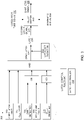
- FIG. 3 is a block diagram 300 illustrating the example latch control logic or rules 240 that are executed by the latch controller 237 of the example CMPE detector 202 of FIG. 2 to determine a state of the latch 238.
- the latch controller 237 executes the latch control rules 240 to determine if the latch 238 should be set to cause the relay switch 242 of the ADRF controller 208 of FIG. 2 to output the synthetic total pressure signal 224 instead of the voted pitot tube signal 220 in response to the detection of a common mode pneumatic event at the pitot tubes 112 of the aircraft 100 of FIG. 1 .
- the latch 238 is considered in the first state when the first latch signal 244 is output by the latch 238, which causes the relay switch 242 to output the voted pitot tube signal 220.
- the latch control rules 240 define a CMPE latch limit 302, or a number of times that the latch 238 can be set to cause the relay switch 242 to output the synthetic total pressure signal 224 in response to the second latch signal 245 from the latch 238.
- the rules 240 limit the number of times that the synthetic total pressure signal 224 is used instead of the voted pitot tube signal 220 to prevent overuse of the synthetic total pressure signal 224 from masking recurring problems at the pitot tubes 112 of the aircraft 100 of FIG. 1 , such as icing or blockage due to debris.
- the CMPE latch limit 302 is set to a predefined maximum limit of occurrences or events (i.e., the latch 238 can be set a threshold number of times during flight to cause the synthetic total pressure signal 224 to be used instead of the voted pitot tube signal 220).
- the CMPE latch limit 302 can be defined based on user inputs and stored in the database 232.
- the latch control rule(s) 240 include a validity check with respect to the estimated dynamic pressure Q bar(e) , or a Q bar(e) valid rule 304.
- a validity or accuracy of the dynamic estimated pressure Q bar(e) i.e., the synthetic dynamic pressure signal 225
- the Q bar(e) valid rule 304 defines expected pressure values for the dynamic estimated pressure Q bar(e) based on, for example, reference or calibration data.
- the latch control rules 240 includes rules to confirm that the signal monitor 234 of the CMPE detector 202 has detected a common mode pneumatic event.
- the example rules 240 include a CMPE detector rule 306.
- the CMPE detector rule 306 is met when the signal monitor 234 identifies a common mode pneumatic event based on the rate of change of the voted dynamic pressure signal 221 and the rate of change of the estimated angle of attack data 230.
- the comparison of the rates of change of the voted dynamic pressure signal 221 and the estimated angle of attack data 230 can indicate that a majority of the pitot tubes 112 are concurrently blocked (e.g., two or more of the pitot tubes are blocked by ice at the same time).
- the example latch control rules 240 include a pitot tube fault rule 308.
- the pitot tube fault rule 308 is met when the signal monitor 234 detects asynchronous drops in pressure measurements at two or more of the pitot tubes 112 based on analysis of the individual rates of change of the pressures signals 212, 214, 216 from the pitot tubes 112, as discussed in connection with FIG. 2 .
- pitot tube fault rule 308 includes logic defining that two or more pitot tubes are to experience a rapid drop in pressure to set the latch 238 to output the synthetic total pressure signal 224. For instance, if one pitot tube out of three pitot tubes is inoperative, the logic can define that the two remaining tubes should experience a rapid drop for a CMPE to be detected. In other examples, if one pitot tube out of two pitot tubes is inoperative, the logic can define that the other remaining tube should experience a rapid drop for a CMPE to be detected. Such logic prevents, for instance, a single inoperative tube (or a number of inoperative tubes that are less than a majority) from interfering with the analysis performed by the CMPE detector 202 because the aircraft may still operate with one pitot tube out of service.
- the CMPE detector rule 306 and the pitot tube fault rule 308 are assigned time limits for which the values of the rules 306, 308 will remain true when executed by the latch controller 237. Such time limits prevent the rules 306, 308 from interfering with decisions by the latch controller 237 to set the latch 238 to output the synthetic total pressure signal 224 or to reset the latch 238 to the first state after the latch 238 is set to the second state (i.e., the state that causes the relay switch 242 to output the synthetic signal). For example, if the CMPE detector rule 306 were always true, then then the latch controller 237 could be prevented from resetting the latch 238.
- the pitot tube fault rule 308 may remain true for a period of time to enable asynchronous pitot tube blockages to be detected. For instance, if a blockage occurs a first pitot tube, the pitot tube fault rule 308 for the first pitot tube will be true for, for instance, x seconds. If y seconds later, a blockage occurs at a second pitot tube, the pitot tube fault rule 308 for the second pitot tube will be true. Because two of the pitot tubes are blocked, the latch controller 237 sets the latch to output the synthetic total pressure signal 224 (i.e., assuming the other latch control rules 240 are satisfied).
- the time limits associated with the rules 306, 308 provide for increased accuracy in determining the state of the latch.
- the latch control rule(s) 240 include an estimated dynamic pressure Q bar(e) inhibited rule 310.
- the Q bar(e) inhibited rule 310 specifies that if the difference between the estimated dynamic pressure Q bar(e) (i.e., the synthetic dynamic pressure signal 225) and the dynamic pressure calculated by the calculator 210 (e.g., signal 248) is greater than a predefined threshold, use of the synthetic total pressure signal 224 is prohibited.
- the calculator 210 calculates the dynamic pressure based on static pressure and the total pressure associated with the one of the voted pitot tube signal 220 or the synthetic total pressure signal 224 (i.e., depending on the state of the latch 238).
- the Q bar(e) inhibited rule 310 specifies that the synthetic total pressure signal 224 should not be used even if the other latch control rules 302, 304, 306, 308 are met.
- the estimated dynamic pressure Q bar(e) value and the dynamic pressure value analyzed by the latch controller 237 when executing the Q bar(e) inhibited rule 310 are associated with a lag filter (e.g., an n second lag).
- the pressure values that are compared by the latch controller 237 when executing the rule 310 are values obtained before the common mode pneumatic event occurs at the pitot tubes 112 and the measured dynamic pressure Q bar(m) is affected by the event.
- the latch controller 237 executes the rules 302, 304, 306, 308, 310 to determine if the latch 238 should be set to the second state such that the second latch signal 245 transmitted by the latch 238 causes the relay switch 242 to output the synthetic total pressure signal 224 instead of the voted pitot tube signal 220.
- the rules 302, 304, 306, 308, 310 to determine if the latch 238 should be set to the second state such that the second latch signal 245 transmitted by the latch 238 causes the relay switch 242 to output the synthetic total pressure signal 224 instead of the voted pitot tube signal 220.
- the latch controller 237 determines that (a) the CMPE latch limit has not been met (rule 302); (b) the estimated dynamic pressure Q bar(e) is valid (rule 304); (c) one of the CMPE detect rule 306 or the pitot tube fault rule 308 has been satisfied, thereby indicating the occurrence of a common mode pneumatic event; and (d) use of the estimated dynamic pressure Q bar(e) is not prohibited (rule 310), then the latch controller 237 determines that the latch 238 should be set to cause the relay switch 242 to output the synthetic total pressure signal 224.
- the latch controller 237 determines that the latch 238 should not be set to enable the synthetic total pressure signal 224 to be output at the relay switch 242. For instance, the latch controller 237 may determine that the CMPE latch limit 302 has been reached such that the latch 238 has been set to the second state the maximum number of times allowed by the limit. In this and some other examples, the latch 238 remains in the first state and the voted pitot tube signal 220 is output by the relay switch 242. Thus, when the latch limit 302 is reached, the synthetic total pressure signal 224 is no longer used to suppress a common mode pneumatic event at the pitot tubes 112.
- the latch controller 237 maintains the latch 238 in the first state and the voted pitot tube signal 220 is output by the relay switch 242.
- the pilot can be alerted (e.g., via the display user interface(s) 254 of FIG. 2 ) to changes in airspeeds calculated from the measured dynamic pressures Q bar(m) of the voted pitot tube signal 220 and take actions to address the cause of the inaccurate reading(s) at the pitot tubes 112.
- an operational mode of a flight control system is changed (e.g., from a normal operational mode to a secondary operational mode).
- the latch controller 237 sets the latch 238 in the second state to cause the synthetic total pressure signal 224 to be output at the relay switch 242 in response to the second latch signal 245, the latch 238 remains in the second state for a predefined amount of time corresponding to a time during which the synthetic total pressure signal 224 is to be output at the relay switch 242.
- the timer 239 of the CMPE detector 202 monitors the time for which the latch 238 is in the second state. When the timer 239 determines that the time period has expired, the latch controller 237 resets the latch 238 to the first state to cause the voted pitot tube signal 220 to be output at the relay switch 242.
- the latch control rules 240 include a latch set duration rule 312.
- the latch set duration rule 312 defines a maximum amount of time that the latch 238 can remain in the second state (e.g., n seconds).
- the duration can be defined based on an expected time for a pitot tube to recover from an icing or other blockage event at the pitot tube such that the pressure represented by the voted pitot tube signal 220 can be considered accurate again.
- the latch set duration rule 312 can be defined based on an expected time for the ice at the pitot tube to be melted by the heater and the sensor readings to return to accurate readings.
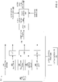
- FIG. 4 is a block diagram 400 illustrating the example latch control logic or rules 240 that are executed by the latch controller 237 of the example CMPE detector 202 of FIG. 2 to determine if the latch 238 should be reset such that the first latch signal 244 is output by the latch 238 to cause the relay switch 242 to switch from outputting the synthetic total pressure signal 224 to outputting the voted pitot tube signal 220. Put another away, the latch 238 returns from the second state to the first state when the latch 238 is reset.
- the latch 238 is set to cause the relay switch 242 to output the synthetic total pressure signal 224 for a period of time (e.g., n seconds) defined by the latch set duration rule 312 as discussed in FIG. 3 .
- the time limit for which the latch 238 is set in the second state corresponds to a time for which the relay switch 242 outputs the synthetic total pressure signal 224.
- the latch control rules 240 include a CMPE latch expiration rule 402.
- the CMPE latch expiration rule 402 states that if the time limit for which the latch 238 is to be set has expired, the latch 238 should be reset.
- the latch 238 is reset (i.e., returned to the first state) by the latch controller 237 prior to expiration of the time limit defined by the latch set duration rule 312 ( FIG. 3 ).
- the latch controller 237 applies the Q bar(e) valid rule 304 to the synthetic dynamic pressure signal 225 as the data is generated by the synthetic pressure signal generator 222 over time.
- the latch controller 237 determines that the estimated dynamic pressure Q bar(e) associated with the synthetic dynamic pressure signal 225 does not satisfy the Q bar(e) valid rule 304 after the latch 238 has been set to the second state (e.g., n seconds after the latch 238 has been set to the second state).
- the latch controller 237 determines that the latch 238 should be reset because the synthetic dynamic pressure signal 225 is no longer accurate.
- the time delay 401 associated with suppression of the common mode pneumatic event via the use of the synthetic total pressure signal 224 ends.
- the latch 238 is reset if the difference between the measured dynamic pressure Q bar(m) (i.e., the voted dynamic pressure signal 221) and the estimated dynamic pressure Q bar(e) (i.e., the synthetic dynamic pressure signal 225) falls within a predefined threshold, thereby indicating that the common mode pneumatic event at the pitot tubes 112 ( FIG. 1 ) has been resolved before expiration of the latch time limit 402.
- the example latch control rules 240 include a Q bar(e) error reset rule 404 defining the threshold pressure difference between the measured dynamic pressure Q bar(m) and the estimated dynamic pressure Q bar(e) such that, when the threshold is satisfied, the measured dynamic pressure Q bar(m) can be considered an accurate pressure measurement.
- the Q bar(e) error reset rule 404 can indicate that if the difference between the measured dynamic pressure Q bar(m) and the estimated dynamic pressure Q bar(e) is less than a predefined percent, then the latch 238 should be reset.
- the latch controller 237 determines that the difference between the measured dynamic pressure Q bar(m) and the estimated dynamic pressure Q bar(e) is within the threshold defined by the Q bar(e) error reset rule 404, the latch controller 237 determines that the latch 238 should be reset to the first state.
- the time delay 401 associated with suppression of the common mode pneumatic event via the use of the synthetic total pressure signal 224 ends and the voted pitot tube signal 220 is output at the relay switch 242.
- the latch control rules 240 define a CMPE detection delay value 406 that defines a time after which the latch controller 237 can execute the Q bar(e) error reset rule 404 (e.g., x seconds).
- the CMPE detection delay value 406 accounts for a delay between a time at which the common mode pneumatic event is detected by the signal monitor 234 of the CMPE detector 202 and the time that the latch controller 237 instructs the latch 238 to be set to the second state in response to the detection of the common mode pneumatic event.
- the latch controller 237 executes the Q bar(e) error reset rule 404 using the measured dynamic pressure Q bar(m) values that are generated after the time defined by CMPE detection delay value 406.
- the latch controller 237 determines if the measured dynamic pressure Q bar(m) values are within the threshold defined by the Q bar(e) error reset rule 404. If the measured dynamic pressure Q bar(m) values satisfy the Q bar(e) error reset rule 404, the latch controller 237 determines that the pitot tubes 112 have recovered from the common mode pneumatic event and the data output by the pitot tubes 112 can be considered accurate.
- the latch controller 237 determines that the latch 238 should be reset if the CMPE latch limit rule 302 indicates that further attempts to set the latch 238 to cause the synthetic total pressure signal 224 to be output are no longer permitted. Put another way, the latch controller 237 determines that the latch 238 should be reset if the latch 238 has been set a number of times exceeding the limit 302 (e.g., n times). In this and some other examples, the CMPE latch limit 302 serves as an additional check to prevent the latch 238 from being erroneously set and, thus, the synthetic total pressure signal 224 from being output, even if other criteria for setting the latch 238 as discussed in connection with FIG. 3 have been met.
- the latch controller 237 determines that a common mode pneumatic event has been detected (rule 306 of FIG. 3 ) but the CMPE latch limit 302 no longer permits the latch 238 to be set to the second state, then the latch controller 237 instructs the latch 238 to be reset (e.g., so as not to hide or mask recurring common mode pneumatic events).
- examples disclosed herein provide for multiple criteria for controlling the state of the latch 238 and, in particular, for controlling when the latch 238 should be set to enable the synthetic total pressure signal 224 to be output by the relay switch 242 or when the latch 238 should be reset to cause the relay switch 242 to return to outputting the voted pitot tube signal 220.
- the multiple criteria checks provide for increased confidence levels with respect to decision by the CMPE detector 202 as to whether the voted pitot tube signal 220 or the synthetic total pressure signal 224 should be used.
- the latch control rules 240 account for recovery of the pitot tubes 112 from the common mode pneumatic event so that the measured dynamic pressure Q bar(m) from the pitot tubes 112 serves as a primary indicator of conditions at the aircraft.
- CMPE detector 202 While an example manner of implementing the CMPE detector 202 is illustrated in FIG. 2 , one or more of the elements, processes and/or devices illustrated in FIG. 2 may be combined, divided, re-arranged, omitted, eliminated and/or implemented in any other way. Further, the example database 232, the signal monitor 234, the example latch controller 237, the example latch 238, the example timer 239, and/or, more generally, the example CMPE detector 202 of FIG. 2 may be implemented by hardware, software, firmware and/or any combination of hardware, software and/or firmware.
- any of the example database 232, the signal monitor 234, the example latch controller 237, the example latch 238, the example timer 239, and/or, more generally, the example CMPE detector 202 could be implemented by one or more analog or digital circuit(s), logic circuits, programmable processor(s), programmable controller(s), graphics processing unit(s) (GPU(s)), digital signal processor(s) (DSP(s)), application specific integrated circuit(s) (ASIC(s)), programmable logic device(s) (PLD(s)) and/or field programmable logic device(s) (FPLD(s)).
- At least one of the example database 232, the signal monitor 234, the example latch controller 237, the example latch 238, and/or the example timer 239 is/are hereby expressly defined to include a non-transitory computer readable storage device or storage disk such as a memory, a digital versatile disk (DVD), a compact disk (CD), a Blu-ray disk, etc. including the software and/or firmware.
- the example CMPE detector 202 of FIG. 2 may include one or more elements, processes and/or devices in addition to, or instead of, those illustrated in FIG. 2 , and/or may include more than one of any or all of the illustrated elements, processes and devices.
- the phrase "in communication,” including variations thereof, encompasses direct communication and/or indirect communication through one or more intermediary components, and does not require direct physical (e.g., wired) communication and/or constant communication, but rather additionally includes selective communication at periodic intervals, scheduled intervals, aperiodic intervals, and/or one-time events.
- FIG. 5 A flowchart representative of example hardware logic, machine readable instructions, hardware implemented state machines, and/or any combination thereof for implementing the CMPE detector 202 of FIG. 2 is shown in FIG. 5 .
- the machine readable instructions may be one or more executable programs or portion(s) of an executable program for execution by a computer processor and/or processor circuitry, such as the processor 612 shown in the example processor platform 600 discussed below in connection with FIG. 6 .
- the program may be embodied in software stored on a non-transitory computer readable storage medium such as a CD-ROM, a floppy disk, a hard drive, a DVD, a Blu-ray disk, or a memory associated with the processor 612, but the entire program and/or parts thereof could alternatively be executed by a device other than the processor 612 and/or embodied in firmware or dedicated hardware.
- a non-transitory computer readable storage medium such as a CD-ROM, a floppy disk, a hard drive, a DVD, a Blu-ray disk, or a memory associated with the processor 612
- the entire program and/or parts thereof could alternatively be executed by a device other than the processor 612 and/or embodied in firmware or dedicated hardware.
- the example program is described with reference to the flowchart illustrated in FIG. 5 , many other methods of implementing the example latch controller 237 may alternatively be used. For example, the order of execution of the blocks may be changed, and/or some of the blocks described
- any or all of the blocks may be implemented by one or more hardware circuits (e.g., discrete and/or integrated analog and/or digital circuitry, an FPGA, an ASIC, a comparator, an operational-amplifier (op-amp), a logic circuit, etc.) structured to perform the corresponding operation without executing software or firmware.
- the processor circuitry may be distributed in different network locations and/or local to one or more devices (e.g., a multi-core processor in a single machine, multiple processors distributed across a server rack, etc).
- the machine readable instructions described herein may be stored in one or more of a compressed format, an encrypted format, a fragmented format, a compiled format, an executable format, a packaged format, etc.
- Machine readable instructions as described herein may be stored as data or a data structure (e.g., portions of instructions, code, representations of code, etc.) that may be utilized to create, manufacture, and/or produce machine executable instructions.
- the machine readable instructions may be fragmented and stored on one or more storage devices and/or computing devices (e.g., servers) located at the same or different locations of a network or collection of networks (e.g., in the cloud, in edge devices, etc.).
- the machine readable instructions may require one or more of installation, modification, adaptation, updating, combining, supplementing, configuring, decryption, decompression, unpacking, distribution, reassignment, compilation, etc. in order to make them directly readable, interpretable, and/or executable by a computing device and/or other machine.
- the machine readable instructions may be stored in multiple parts, which are individually compressed, encrypted, and stored on separate computing devices, wherein the parts when decrypted, decompressed, and combined form a set of executable instructions that implement one or more functions that may together form a program such as that described herein.
- machine readable instructions may be stored in a state in which they may be read by processor circuitry, but require addition of a library (e.g., a dynamic link library (DLL)), a software development kit (SDK), an application programming interface (API), etc. in order to execute the instructions on a particular computing device or other device.
- a library e.g., a dynamic link library (DLL)
- SDK software development kit
- API application programming interface
- the machine readable instructions may need to be configured (e.g., settings stored, data input, network addresses recorded, etc.) before the machine readable instructions and/or the corresponding program(s) can be executed in whole or in part.
- machine readable media may include machine readable instructions and/or program(s) regardless of the particular format or state of the machine readable instructions and/or program(s) when stored or otherwise at rest or in transit.
- the machine readable instructions described herein can be represented by any past, present, or future instruction language, scripting language, programming language, etc.
- the machine readable instructions may be represented using any of the following languages: C, C++, Java, C#, Perl, Python, JavaScript, HyperText Markup Language (HTML), Structured Query Language (SQL), Swift, etc.
- the example processes of FIG. 5 may be implemented using executable instructions (e.g., computer and/or machine readable instructions) stored on a non-transitory computer and/or machine readable medium such as a hard disk drive, a flash memory, a read-only memory, a compact disk, a digital versatile disk, a cache, a random-access memory and/or any other storage device or storage disk in which information is stored for any duration (e.g., for extended time periods, permanently, for brief instances, for temporarily buffering, and/or for caching of the information).
- a non-transitory computer readable medium is expressly defined to include any type of computer readable storage device and/or storage disk and to exclude propagating signals and to exclude transmission media.
- A, B, and/or C refers to any combination or subset of A, B, C such as (1) A alone, (2) B alone, (3) C alone, (4) A with B, (5) A with C, (6) B with C, and (7) A with B and with C.
- the phrase "at least one of A and B" is intended to refer to implementations including any of (1) at least one A, (2) at least one B, and (3) at least one A and at least one B.
- the phrase "at least one of A or B" is intended to refer to implementations including any of (1) at least one A, (2) at least one B, and (3) at least one A and at least one B.
- the phrase "at least one of A and B" is intended to refer to implementations including any of (1) at least one A, (2) at least one B, and (3) at least one A and at least one B.
- the phrase "at least one of A or B" is intended to refer to implementations including any of (1) at least one A, (2) at least one B, and (3) at least one A and at least one B.
- FIG. 5 is a flowchart of example instructions 500 that can be executed by the CMPE detector 202 of FIG. 2 (e.g., the signal monitor 234, the latch controller 237) to control output of a measured total pressure signal (e.g., the voted pitot tube signal 220) or an estimated total pressure signal (e.g., the synthetic total pressure signal 224) for use in determining airspeed metrics of an aircraft (e.g., the aircraft 100 of FIG. 1 ).
- the example instructions 500 begin with the latch 238 in a first state, or a state in which the first latch signal 244 is output by the latch 238 to cause the relay switch 242 of the ADRF controller 208 to output the voted pitot tube signal 220 (block 502).
- the latch 238 remains in the first state until the signal monitor 234 of the CMPE detector 202 detects a common mode pneumatic event at the pitot tubes 112 of the aircraft 100 (e.g., when a majority of the pitot tubes 112 are blocked) (block 504).
- the signal monitor 234 can identify a common mode pneumatic event based on the rate of change of the voted dynamic pressure signal 221 and the rate of change of the estimated angle of attack data 230.
- the latch controller 237 determines that the CMPE detector rule 306 of the latch control rules 240 is satisfied.
- the signal monitor 234 detects the common mode pneumatic event based on analysis of the individual rates of change of the pressures signals 212, 214, 216 from the pitot tubes 112. In such examples, the latch controller 237 determines that the pitot tube fault rule 308 of the latch control rules 240 is satisfied.
- the latch controller 237 performs a series of checks to confirm that the latch 238 should be set in the second state to cause the synthetic total pressure signal 224 to be output at the relay switch 242. For instance, the latch controller 237 confirms that the limit for setting the latch 238 in the second state has not been reached (block 506).
- the latch control rules 240 include CMPE latch limit 302 that defines the number of times that the latch 238 can be set to cause the relay switch 242 to output the synthetic total pressure signal 224 in response to the second latch signal 245 from the latch 238. In the example of FIG. 5 , if the CMPE latch limit 302 has been reached, the latch controller 237 maintains the latch 238 in the first state.
- the latch controller 237 confirms a validity or accuracy of the dynamic estimated pressure Q bar(e) generated by the synthetic pressure signal generator 222 based on the Q bar(e) valid rule 304 and reference estimated pressure data (block 508).
- the latch controller 237 confirms that use of the synthetic total pressure signal 224 is not prohibited based on the Q bar(e) inhibited rule 310, which indicates that if the difference between the estimated dynamic pressure Q bar(e) and the dynamic pressure calculated by the calculator 210 (e.g., signal 248) is greater than a predefined threshold, use of the synthetic total pressure signal 224 is prohibited (block 510).
- latch controller 237 maintains the latch 238 in the first state. If the rules 302, 304, 308, 310 in blocks 504-508 are satisfied, the latch controller 237 sets the latch 238 in the second state (block 512). In the second state, the second latch signal 245 is output by the latch 238 to cause the relay switch 242 to output the synthetic total pressure signal 224.
- the latch controller 237 of FIG. 2 also determines when the latch 238 should be reset to enable the relay switch 242 to switch or return to outputting the voted pitot tube signal 220.
- the latch set duration rule 312 defines a maximum amount of time for which the latch 238 is to remain in the second state.
- the latch set duration rule 312 corresponds to a maximum amount of time that the synthetic total pressure signal 224 is to be output to prevent the synthetic total pressure signal 224 from hiding ongoing blockage problems at the pitot tubes 112. If the timer 239 of the CMPE detector 202, determines that the latch set time limit has expired, the latch controller 237 resets the latch 238 to the first state (blocks 514, 520).
- the latch controller 237 performs other checks to determine if the latch 238 should be reset to the first state.
- the latch controller 237 applies the Q bar(e) valid rule 304 to the synthetic dynamic pressure signal 225 as the data is generated by the synthetic pressure signal generator 222 over time to determine if there are any changes in the validity of the synthetic dynamic pressure signal 225 that would warrant resetting the latch 238 to cause output of the synthetic total pressure signal 224 to end (blocks 516, 520).
- the latch controller 237 executes the Q bar(e) error reset rule 404 to determine difference between the measured dynamic pressure Q bar(m) (i.e., the voted dynamic pressure signal 221) associated with the voted pitot tube signal 220 and the estimated dynamic pressure Q bar(e) of the synthetic total pressure signal 224 falls within a predefined threshold, thereby indicating that the common mode pneumatic event at the pitot tubes 112 has been resolved before expiration of the latch time limit. If the voted pitot tube signal 220 has recovered, the latch controller 237 resets the latch 238 (blocks 518, 520).
- the example instructions 500 continue to monitor for common mode pneumatic events at the pitot tubes during flight (block 522, 524). The example instructions 500 end when the aircraft has landed (block 526).
- FIG. 6 is a block diagram of an example processor platform 600 structured to execute the instructions of FIG. 5 to implement the CMPE detector 202 of FIG.5 .
- the processor platform 600 can be, for example, a server, a personal computer, a workstation, a self-learning machine (e.g., a neural network), a mobile device (e.g., a cell phone, a smart phone, a tablet such as an iPad TM ), a personal digital assistant (PDA), an Internet appliance, or any other type of computing device.
- a self-learning machine e.g., a neural network
- a mobile device e.g., a cell phone, a smart phone, a tablet such as an iPad TM
- PDA personal digital assistant
- the processor platform 600 of the illustrated example includes a processor 612.
- the processor 612 of the illustrated example is hardware.
- the processor 612 can be implemented by one or more integrated circuits, logic circuits, microprocessors, GPUs, DSPs, or controllers from any desired family or manufacturer.
- the hardware processor may be a semiconductor based (e.g., silicon based) device.
- the processor implements the example signal monitor 234, the example latch controller 237, the example latch 238, and the example timer 239.
- the processor 612 of the illustrated example includes a local memory 613 (e.g., a cache).
- the processor 612 of the illustrated example is in communication with a main memory including a volatile memory 614 and a non-volatile memory 616 via a bus 618.
- the volatile memory 614 may be implemented by Synchronous Dynamic Random Access Memory (SDRAM), Dynamic Random Access Memory (DRAM), RAMBUS ® Dynamic Random Access Memory (RDRAM ® ) and/or any other type of random access memory device.
- the non-volatile memory 616 may be implemented by flash memory and/or any other desired type of memory device. Access to the main memory 614, 616 is controlled by a memory controller.
- the processor platform 600 of the illustrated example also includes an interface circuit 620.
- the interface circuit 620 may be implemented by any type of interface standard, such as an Ethernet interface, a universal serial bus (USB), a Bluetooth ® interface, a near field communication (NFC) interface, and/or a PCI express interface.
- one or more input devices 622 are connected to the interface circuit 620.
- the input device(s) 622 permit(s) a user to enter data and/or commands into the processor 612.
- the input device(s) can be implemented by, for example, an audio sensor, a microphone, a camera (still or video), a keyboard, a button, a mouse, a touchscreen, a track-pad, a trackball, isopoint and/or a voice recognition system.
- one or more output devices 624 are also connected to the interface circuit 620.
- the output devices 624 can be implemented, for example, by display devices (e.g., a light emitting diode (LED), an organic light emitting diode (OLED), a liquid crystal display (LCD), a cathode ray tube display (CRT), an in-place switching (IPS) display, a touchscreen, etc.), a tactile output device, a printer and/or speaker.
- the interface circuit 620 thus, may include a graphics driver card, a graphics driver chip and/or a graphics driver processor.
- the interface circuit 620 of some examples including the illustrated example also include a communication device such as a transmitter, a receiver, a transceiver, a modem, a residential gateway, a wireless access point, and/or a network interface to facilitate exchange of data with external machines (e.g., computing devices of any kind) via a network 626.
- the communication can be via, for example, an Ethernet connection, a digital subscriber line (DSL) connection, a telephone line connection, a coaxial cable system, a satellite system, a line-of-site wireless system, a cellular telephone system, etc.
- DSL digital subscriber line
- the processor platform 600 of some examples including the illustrated example also include one or more mass storage devices 628 for storing software and/or data.
- mass storage devices 628 include floppy disk drives, hard drive disks, compact disk drives, Blu-ray disk drives, redundant array of independent disks (RAID) systems, and digital versatile disk (DVD) drives.
- Machine executable instructions 632 may be stored in the mass storage device 628, in the volatile memory 614, in the non-volatile memory 616, and/or on a removable non-transitory computer readable storage medium such as a CD or DVD.
- CMPE common mode pneumatic event detector
- CMPE detector provides for detection of common mode pneumatic events to augment the detection of the common mode pneumatic events by a common mode monitor of the aircraft.
- the example CMPE detector selectively transmits a signal to a relay switch to cause the relay switch to output one of a pressure signal generated by the pitot tubes or an estimated pressure signal.
- the estimated pressure signal can be used instead of the actual pressure signal to provide consistent airspeed data to a pilot while blockage events such as icing at the pitot tubes that caused the common mode pneumatic event are resolved.
- the example CMPE detector disclosed herein executes multiple rules or logic to confirm that the actual pressure signal should be temporarily replaced with the estimated pressure signal and to determine when use of the actual pressure signal should resume. Examples disclosed herein dynamically respond to changes in conditions at the pitot tubes to control the output of the actual pressure signal or the estimated pressure signal.
- Example 1 includes a system including a common mode pneumatic event detector to detect a common mode pneumatic event at pitot tubes of an aircraft, a latch, a relay switch in communication with the latch, and a latch controller to set the latch in a first state to cause the latch to output a first latch signal, the relay switch to output a first pressure signal in response to the first latch signal, the first pressure signal based on pressure data from the pitot tubes, and set the latch in a second state to cause the latch to output a second latch signal based on the detection of the common mode pneumatic event.
- the relay switch is to output a second pressure signal in response to the second latch signal.
- the second pressure signal includes estimated pressure data.
- Example 2 includes the system of example 1, wherein the common mode pneumatic event detector is to detect the common mode pneumatic event based on a respective rate of change of the pressure data associated with the pitot tubes.
- Example 3 includes the system of example 2, wherein the pressure data is based on signals from at least three pitot tubes.
- Example 4 includes the system of any of examples 1-3, wherein the common mode pneumatic event detector is to detect the common mode pneumatic event based on a rate of change of estimated angle of attack data, the estimated angle of attack data based on the pressure data from the pitot tubes.
- Example 5 includes the system of any of examples 1-4, wherein the latch controller to determine a limit for a number of times in which the latch is to be set in the second state and refrain from setting the latch in the second state when the limit has been satisfied .
- Example 6 includes the system of any of examples 1-5, wherein the latch controller is to determine a differential between the second pressure signal and the first pressure signal, perform a comparison of the differential to a pressure difference threshold, and set the latch in the first state if the differential satisfies the pressure difference threshold.
- Example 7 includes the system of any of examples 1-6, further including a timer to determine a time limit for which the latch is in the second state, the latch controller to set the latch in the first state based on the time limit.
- Example 8 includes the system of example 7, wherein the relay switch is to output the second pressure signal for a duration of time corresponding to the time limit.
- Example 9 includes the system of any of examples 1-8, further including a calculator to calculate a parameter of the aircraft based on the first pressure signal when the latch is in the first state and calculate the parameter of the aircraft based on the second pressure signal when the latch is in the second state, the parameter including one or more of airspeed, dynamic pressure, or a mach number.
- Example 10 includes the system of any of examples 1-9, further including a common mode monitor to determine an operational mode of a flight control system of the aircraft based on the latch being in the first state or the second state.
- Example 11 includes a method including causing a relay switch to output a first pressure signal, the first pressure signal indicative of a pressure measured at one or more pitot tubes of an aircraft, detecting a common mode pneumatic event at the pitot tubes of the aircraft based on the pressure measured at the one or more pitot tubes, and causing the relay switch from outputting the first pressure signal to outputting a second pressure signal in response to the detection of the common mode pneumatic event.
- the second pressure signal is indicative of an estimated pressure.
- the second pressure signal is to be used to determine one or more airspeed parameters of the aircraft.
- Example 12 includes the method of example 11, further including causing the relay switch to switch from outputting the second pressure signal to outputting the first pressure signal after a predefined period of time.
- Example 13 includes the method of example 11 or 12, further including determining a pressure difference between the first pressure signal to the second pressure signal, performing a comparison of the pressure difference to a threshold, and causing the relay switch to switch from outputting the second pressure signal to outputting the first pressure signal based on the comparison.
- Example 14 includes the method of any of examples 11-13, further including causing at least one processor to validate the second pressure signal based on reference estimated pressure data.
- Example 15 includes a system including an air data reference function controller to generate a pitot tube pressure signal based on pressure signals output by pitot tubes of an aircraft, the air data reference function controller including a relay, a synthetic signal pressure signal generator to generate an estimated pressure signal, a calculator, and a common mode pneumatic event detector in communication with the relay.
- the common mode pneumatic event detector is to generate a first instruction to cause the air data reference function controller to output the pitot tube pressure signal to the calculator, detect a common mode pneumatic event at the pitot tubes, and generate a second instruction to cause the air data reference function controller to output the estimated pressure signal to the calculator in response to the detection of the common mode pneumatic event.
- the estimated pressure signal is to replace pitot tube pressure signal.
- the calculator is to determine an airspeed of the aircraft based on the one of (a) the pitot tube pressure signal or (b) the estimated pressure signal.
- Example 16 includes the system of example 15, wherein the common mode pneumatic event detector is to generate a third instruction to cause the air data reference function controller to output the pitot tube pressure signal to the calculator, the pitot tube pressure signal to replace the estimated pressure signal.
- Example 17 includes the system of example 16, wherein the common mode pneumatic event detector is to detect an expiration of a time limit for which the air data reference function controller is to output the estimated pressure signal, the common mode pneumatic event detector to generate the third instruction in response to the expiration of the time limit.
- Example 18 includes the system of examples 15 or 16, wherein the common mode pneumatic event detector includes a latch, the first instruction based on a first signal generated by the latch when the latch is in a first state and the second instruction based on a second signal generated by the latch when the latch is in a second state.
- the common mode pneumatic event detector includes a latch, the first instruction based on a first signal generated by the latch when the latch is in a first state and the second instruction based on a second signal generated by the latch when the latch is in a second state.
- Example 19 includes the system of example 18, wherein the common mode pneumatic event detector is to change a state of the latch from the first state to the second state in response to the detection of the common mode pneumatic event.
- Example 20 includes the system of any of examples 15-19, wherein the common mode pneumatic event detector is to generate a third instruction to cause the air data reference function controller to output the pitot tube pressure signal to the calculator, the pitot tube pressure signal to replace the estimated pressure signal, determine that a difference between the estimated pressure signal and the pitot tube pressure signal exceeds a threshold, and maintain the third instruction to cause the air data reference function controller to output the pitot tube pressure signal in response to the difference exceeding the threshold.
- the common mode pneumatic event detector is to generate a third instruction to cause the air data reference function controller to output the pitot tube pressure signal to the calculator, the pitot tube pressure signal to replace the estimated pressure signal, determine that a difference between the estimated pressure signal and the pitot tube pressure signal exceeds a threshold, and maintain the third instruction to cause the air data reference function controller to output the pitot tube pressure signal in response to the difference exceeding the threshold.
- Example 21 includes the system of any of examples 15-20, wherein the common mode pneumatic event detector is to generate a third instruction to cause the air data reference function controller to output the pitot tube pressure signal to the calculator, the pitot tube pressure signal to replace the estimated pressure signal, determine that a difference between the estimated pressure signal and the pitot tube pressure signal exceeds a threshold, and maintain the third instruction to provide for the air data reference function controller to output the pitot tube pressure signal in response to the difference exceeding the threshold.
- the common mode pneumatic event detector is to generate a third instruction to cause the air data reference function controller to output the pitot tube pressure signal to the calculator, the pitot tube pressure signal to replace the estimated pressure signal, determine that a difference between the estimated pressure signal and the pitot tube pressure signal exceeds a threshold, and maintain the third instruction to provide for the air data reference function controller to output the pitot tube pressure signal in response to the difference exceeding the threshold.
- Example 22 includes the system of any of examples 15-21, wherein the pitot tube pressure signal includes total pressure data.
- Example 23 includes a non-transitory computer readable medium comprising instructions that, when executed by at least one processor, cause the at least one processor to cause a relay switch to output a first pressure signal, the first pressure signal indicative of a pressure measured at one or more pitot tubes of an aircraft; detect a common mode pneumatic event at the pitot tubes of the aircraft based on the pressure measured at the one or more pitot tubes; and cause the relay switch from outputting the first pressure signal to outputting a second pressure signal in response to the detection of the common mode pneumatic event.
- the second pressure signal is indicative of an estimated pressure.
- the second pressure signal is to be used to determine one or more airspeed parameters of the aircraft.
- Example 24 includes the non-transitory computer readable medium of example 23, wherein the instructions, when executed, cause the at least one processor to cause the relay switch to switch from outputting the second pressure signal to outputting the first pressure signal after a predefined period of time.
- Example 25 includes the non-transitory computer readable medium of example 23 or 24, wherein the instructions, when executed, cause the at least one processor to determine a pressure difference between the first pressure signal and the second pressure signal; and perform a comparison of the pressure difference to a threshold; and cause the relay switch to switch from outputting the second pressure signal to outputting the first pressure signal based on the comparison.
- Example 26 includes the non-transitory computer readable medium of any of examples 23-255, wherein the instructions, when executed, cause the at least one processor to validate the second pressure signal based on reference estimated pressure data.
- Example 27 includes an aircraft that comprises the system of example 9 or example 10 in combination with example 9, and the aircraft further comprises: an air data reference function controller configured to generate a pitot tube pressure signal based on pressure signals output by the pitot tubes of the aircraft, the air data reference function controller including the relay switch; and a synthetic signal pressure signal generator configured to generate an estimated pressure signal; wherein: the common mode pneumatic event detector is in communication with the relay switch; and the common mode pneumatic event detector is configured to: generate a first instruction to cause the air data reference function controller to output the pitot tube pressure signal to the calculator; detect a common mode pneumatic event at the pitot tubes; and generate a second instruction to cause the air data reference function controller to output the estimated pressure signal to the calculator in response to the detection of the common mode pneumatic event, the estimated pressure signal to replace pitot tube pressure signal, the calculator to determine an airspeed of the aircraft based on the one of (a) the pitot tube pressure signal or (b) the estimated pressure signal.
- the common mode pneumatic event detector is in communication with
- Example 28 includes the system of example 27, wherein the common mode pneumatic event detector is to generate a third instruction to cause the air data reference function controller to output the pitot tube pressure signal to the calculator, the pitot tube pressure signal to replace the estimated pressure signal.
- Example 29 includes the system of example 28, wherein the common mode pneumatic event detector is to detect an expiration of a time limit for which the air data reference function controller is to output the estimated pressure signal, the common mode pneumatic event detector to generate the third instruction in response to the expiration of the time limit.
- Example 30 includes the system of examples 27 or 29, wherein the common mode pneumatic event detector includes a latch, the first instruction based on a first signal generated by the latch when the latch is in a first state and the second instruction based on a second signal generated by the latch when the latch is in a second state.
- the common mode pneumatic event detector includes a latch, the first instruction based on a first signal generated by the latch when the latch is in a first state and the second instruction based on a second signal generated by the latch when the latch is in a second state.
- Example 31 includes the system of example 30, wherein the common mode pneumatic event detector is to change a state of the latch from the first state to the second state in response to the detection of the common mode pneumatic event.
- Example 32 includes the system of any of examples 27-31, wherein the common mode pneumatic event detector is to generate a third instruction to cause the air data reference function controller to output the pitot tube pressure signal to the calculator, the pitot tube pressure signal to replace the estimated pressure signal, determine that a difference between the estimated pressure signal and the pitot tube pressure signal exceeds a threshold, and maintain the third instruction to cause the air data reference function controller to output the pitot tube pressure signal in response to the difference exceeding the threshold.
- the common mode pneumatic event detector is to generate a third instruction to cause the air data reference function controller to output the pitot tube pressure signal to the calculator, the pitot tube pressure signal to replace the estimated pressure signal, determine that a difference between the estimated pressure signal and the pitot tube pressure signal exceeds a threshold, and maintain the third instruction to cause the air data reference function controller to output the pitot tube pressure signal in response to the difference exceeding the threshold.
- Example 33 includes the system of any of examples 27-32, wherein the common mode pneumatic event detector is to generate a third instruction to cause the air data reference function controller to output the pitot tube pressure signal to the calculator, the pitot tube pressure signal to replace the estimated pressure signal, determine that a difference between the estimated pressure signal and the pitot tube pressure signal exceeds a threshold, and maintain the third instruction to provide for the air data reference function controller to output the pitot tube pressure signal in response to the difference exceeding the threshold.
- the common mode pneumatic event detector is to generate a third instruction to cause the air data reference function controller to output the pitot tube pressure signal to the calculator, the pitot tube pressure signal to replace the estimated pressure signal, determine that a difference between the estimated pressure signal and the pitot tube pressure signal exceeds a threshold, and maintain the third instruction to provide for the air data reference function controller to output the pitot tube pressure signal in response to the difference exceeding the threshold.
- Example 34 includes the system of any of examples 27-33, wherein the pitot tube pressure signal includes total pressure data.
Landscapes
- Engineering & Computer Science (AREA)
- Aviation & Aerospace Engineering (AREA)
- Physics & Mathematics (AREA)
- General Physics & Mathematics (AREA)
- Automation & Control Theory (AREA)
- Measuring Fluid Pressure (AREA)
- Traffic Control Systems (AREA)
Abstract
Description
- This disclosure relates generally to flight control systems, and, more particularly, to apparatus, systems and methods for managing common mode pneumatic events.
- An aircraft includes pitot tubes (also known in some instances as pitot probes) that output pressure sensor data during flight. Data from the pitot tubes is used to determine metrics for the aircraft such as speed.
- An example system includes a common mode pneumatic event detector to detect a common mode pneumatic event at pitot tubes of an aircraft, a latch, a relay switch in communication with the latch, and a latch controller to set the latch in a first state to cause the latch to output a first latch signal, the relay switch to output a first pressure signal in response to the first latch signal, the first pressure signal based on pressure data from the pitot tubes, and set the latch in a second state to cause the latch to output a second latch signal based on the detection of the common mode pneumatic event. The relay switch is to output a second pressure signal in response to the second latch signal. The second pressure signal includes estimated pressure data.
- An example method includes causing a relay switch to output a first pressure signal, the first pressure signal indicative of a pressure measured at one or more pitot tubes of an aircraft, detecting a common mode pneumatic event at the pitot tubes of the aircraft based on the pressure measured at the one or more pitot tubes, and causing the relay switch from outputting the first pressure signal to outputting a second pressure signal in response to the detection of the common mode pneumatic event. The second pressure signal is indicative of an estimated pressure. The second pressure signal is to be used to determine one or more airspeed parameters of the aircraft.
- Another example system an air data reference function controller to generate a pitot tube pressure signal based on pressure signals output by pitot tubes of an aircraft, the air data reference function controller including a relay, a synthetic signal pressure signal generator to generate an estimated pressure signal, a calculator, and a common mode pneumatic event detector in communication with the relay. The common mode pneumatic event detector is to generate a first instruction to cause the air data reference function controller to output the pitot tube pressure signal to the calculator, detect a common mode pneumatic event at the pitot tubes, and generate a second instruction to cause the air data reference function controller to output the estimated pressure signal to the calculator in response to the detection of the common mode pneumatic event. The estimated pressure signal is to replace pitot tube pressure signal. The calculator is to determine an airspeed of the aircraft based on the one of (a) the pitot tube pressure signal or (b) the estimated pressure signal.
- An example non-transitory computer readable medium includes instructions that, when executed by at least one processor, cause the at least one processor to cause a relay switch to output a first pressure signal, the first pressure signal indicative of a pressure measured at one or more pitot tubes of an aircraft, detect a common mode pneumatic event at the pitot tubes of the aircraft based on the pressure measured at the one or more pitot tubes, and cause the relay switch from outputting the first pressure signal to outputting a second pressure signal in response to the detection of the common mode pneumatic event. The second pressure signal is indicative of an estimated pressure. The second pressure signal is to be used to determine one or more airspeed parameters of the aircraft.
-
-
FIG. 1 illustrates an example air vehicle in which examples disclosed herein may be implemented. -
FIG. 2 is block diagram of an example common mode pneumatic event control system including an example implementation of a common mode pneumatic event detector for detecting a common mode pneumatic event at pitot tubes of the example air vehicle ofFIG. 1 . -
FIG. 3 is a block diagram of example control rules that are implemented by the example common mode pneumatic event detector ofFIG. 2 to cause a synthetic pressure signal to be output. -
FIG. 4 is a block diagram of example control rules that are implemented by the example common mode pneumatic event detector ofFIG. 2 to cause a pressure signal generated by the pitot tubes of the air vehicle ofFIG. 1 to be output. -
FIG. 5 is a flowchart representative of machine readable instructions which may be executed to implement the example common mode pneumatic event detector ofFIG. 2 . -
FIG. 6 is a block diagram of an example processing platform structured to execute the instructions ofFIG. 5 to implement the example common mode pneumatic event detector ofFIG. 2 . - The figures are not to scale. Instead, the thickness of the layers or regions may be enlarged in the drawings. In general, the same reference numbers will be used throughout the drawing(s) and accompanying written description to refer to the same or like parts.
- Unless specifically stated otherwise, descriptors such as "first," "second," "third," etc. are used herein without imputing or otherwise indicating any meaning of priority, physical order, arrangement in a list, and/or ordering in any way, but are merely used as labels and/or arbitrary names to distinguish elements for ease of understanding the disclosed examples. In some examples, the descriptor "first" may be used to refer to an element in the detailed description, while the same element may be referred to in a claim with a different descriptor such as "second" or "third." In such instances, it should be understood that such descriptors are used merely for identifying those elements distinctly that might, for example, otherwise share a same name.
- An aircraft includes pitot tubes that output pressure data during flight. Data from the pitot tubes is used to determine metrics for the aircraft such as speed. The pressure readings from the individual pitot tubes can be averaged or used to select a midpoint value from the individual signals to obtain a total pressure measurement. The total pressure measurement is used to determine aircraft speed.
- During flight, the pitot tubes can become blocked due to ice, debris (e.g., volcanic ash), insects, bird strikes, etc. A common mode pneumatic event occurs when a majority of the pitot tubes are blocked or otherwise not operating correctly at the same time or substantially the same time (e.g., within a time frame of milliseconds to seconds). As a result of the blocked pitot tubes, the total pressure measurement and, thus, the airspeed values calculated therefrom, are inaccurate. For instance, when the total pressure measurement is low due to blocked pitot tubes, the calculated airspeed can indicate that the aircraft is rapidly losing speed or stalling. In response to such erroneous data, a pilot may respond with overaggressive maneuvers of the aircraft, such as a pushover maneuver.
- In some instances, common mode pneumatic events at the pitot tubes are resolved over time. For instance, icing events at the pitot tubes can be resolved via heat, which enables the pitot tube pressure readings and the aircraft speeds calculated therefrom to return to accurate values. To prevent unwarranted alerts to the pilot that could prompt the pilot to take unnecessary actions while blockage events at the pitot tubes are being resolved, a synthetic or estimated pressure signal can be used instead of the pressure signals from the pitot tubes, as disclosed in
U.S. Patent Application No. 15/620,224 andU.S. Patent Application No. 16/213,406 . The synthetic pressure data can be used instead of the pressure data measured at the pitot tubes to determine airspeeds until the pitot tube readings return to normal. - For instance, in response to detection of a common mode pneumatic event by a common mode monitor of an aircraft, a flight control system of the aircraft can operate in an extended normal mode for a predefined period of time in which (e.g., a time delay during which) estimated pressure values in the synthetic signal are used to calculate airspeeds instead of the measured pressure values from the pitot tubes. Thus, the pilot does not detect a significant change in airspeed data. Rather, the common mode pneumatic event is suppressed for a period of time by use of the synthetic signal data. During this period of time, systems of the aircraft such as the flight control system, an autopilot control system, and an autothrottle control system operate using metrics generated based on the estimated pressures. However, if the common mode pneumatic event continues to be detected after the time delay, the actual pitot tube pressure data is used to calculate airspeeds, which can alert the pilot to ongoing or recurring blockage events at the pitot tubes.
- Disclosed herein are example systems and methods that provide a flight control system architecture to manage common mode pneumatic events. Examples may include a common mode pneumatic event (CMPE) detector to identify common mode pneumatic events at pitot tubes (also known in some instances as pitot probes) of an air vehicle and to dynamically respond to the occurrence of such events (i.e., ice blockage) as well as the resolution of such events (e.g., melting of the ice). The CMPE detector may control a latch to cause output of one of (a) signal data including total pressure measured by the pitot tubes or (b) synthetic signal data including estimated total pressure. Examples may implement multiple criteria for determining if the synthetic signal should be output instead of the total pressure measured by the signal data generated at the pitot tubes.
- Metrics or parameters such as airspeeds of the aircraft may be determined using the selected signal data (e.g., the actual total pressures measured at the pitot tubes or the estimated total pressures of the synthetic signal). Examples may limit a number of times that the latch is set to cause the synthetic signal to be output. This limit accounts for recovery of the blockage events at the pitot tubes and promotes a return to the use of the actual measured data provided by the pitot tubes. The limit on the number of times the latch can be set to output the synthetic signal also prevents a flight control system from failing to alert a pilot of ongoing or recurring problems at the pitot tubes that require attention. In some examples, the CMPE detector augments the detection of common mode pneumatic events at the pitot tubes by a common mode monitor of the aircraft by dynamically responding to the occurrence of or the resolution of the common mode pneumatic events and corresponding use of the synthetic pressure signal.
-
FIG. 1 illustrates anexample aircraft 100 in which the examples disclosed herein may be implemented. Theaircraft 100 includesstabilizers 102 andwings 104 coupled to afuselage 106. Thewings 104 of theaircraft 100 havecontrol surfaces 108 located along the leading and/or trailing edges of thewings 104. Thecontrol surfaces 108 may be displaced or adjusted (e.g., angled, etc.) to provide lift during takeoff, landing and/or flight maneuvers. Thecontrol surfaces 108 include, for instance, leading edge flaps, leading edge slats, upper spoilers (e.g., flight spoilers, ground spoilers, upper surface spoilers, etc.), and trailing edge flaps (e.g., rotatable flaps). In this and other examples, thestabilizers 102 include arudder 110. - The
aircraft 100 includes anacelle 111 coupled to eachwing 104. Eachnacelle 111 houses anengine 113. - The
aircraft 100 ofFIG. 1 may include a plurality of sensors to collect data during flight of theaircraft 100. Theaircraft 100 may include a plurality ofpitot tubes 112 including afirst pitot tube 114 and asecond pitot tube 116 on afirst side 118 of thefuselage 106 and a third pitot tube (not shown) on asecond side 120 of theaircraft 100. In some examples including the example ofFIG. 1 , thepitot tubes 112 are disposed at anose 122 of theaircraft 100. However, thepitot tubes 112 can be located at other locations on theaircraft 100. Theaircraft 100 can include additional or fewer pitot tubes than shown inFIG. 1 . - The
aircraft 100 includesstatic ports 124 located on eachside aircraft 100 between thepitot tubes 112 and thewings 104. Theaircraft 100 can include additionalstatic ports 124 than shown inFIG. 1 - Example aircraft such as the
aircraft 100 ofFIG. 1 , may include angle ofattack sensors 126. Although only one angle ofattack sensor 126 is shown inFIG. 1 , theaircraft 100 can include additional angle of attack sensors 126 (e.g., additional sensors located on thesecond side 120 of the fuselage 106). -
Example aircraft 100 may include engine pressure and/or fan speed sensors (not shown) disposed at theengines 113. Also,example aircraft 100 can include additional sensors such as temperature sensors (e.g., engine air temperature probes) and inertial data sensors (e.g., accelerometers, gyroscopes), and/or sensors to measure deflection of the control surface(s) 108 of theaircraft 100. -
FIG. 2 is a block diagram of an example common mode pneumatic event (CMPE)control system 200 for detecting common mode pneumatic events, or blockages of pitot tubes of an aircraft (e.g., blockages at a majority of the pitot tubes). The exampleCMPE control system 200 ofFIG. 2 can be implemented at theexample aircraft 100 ofFIG. 1 to address common mode pneumatic events at thepitot tubes 112 of theaircraft 100. - Some example CMPE control systems like the
CMPE control system 200 ofFIG. 2 include aCMPE detector 202 that is implemented by aflight control system 204 of theaircraft 100 ofFIG. 1 . Theflight control system 204 is implemented by one or more processors (e.g., flight control computers). Some exampleCMPE control systems 200 include acommon mode monitor 206, an air data reference function (ADRF)controller 208, and acalculator 210. Thecommon mode monitor 206, theADRF controller 208, and thecalculator 210 can be implemented by avionics (e.g., processor(s), electronics) of theaircraft 100. - Some
example ADRF controllers 208 include apitot source selector 211. Thepitot source selector 211 may receive signal data representative of pressures detected at therespective pitot tubes 112 of theaircraft 100 ofFIG. 1 . For instance, thepitot source selector 211 receives first pressure signal data 212 from a first pitot tube of theaircraft 100 ofFIG. 1 (e.g., the first pitot tube 114), second pressure signal data 214 from a second pitot tube of the aircraft 100 (e.g., the second pitot tube 116), and third pressure signal data 216 from a third pitot tube of theaircraft 100. The pitot tube pressure data 212, 214, 216 can be stored in adatabase 218. In some examples, thepitot source selector 211 includes thedatabase 218. In other examples, thedatabase 218 is located external to thepitot source selector 211 in a location accessible to thepitot source selector 211, as shown inFIG. 2 . - The
pitot source selector 211 analyzes the signal data 212, 214, 216 from thepitot tubes 112 to generate a votedpitot tube signal 220. The votedpitot tube signal 220 represents measured total pressure Ptot(m) calculated from the pitot tube signal data 212, 214, 216. In some examples, thepitot source selector 211 averages the pressure values associated with the signal data 212, 214, 216 to generate the total pressure value Ptot(m). In other examples, thepitot source selector 211 selects one of the pitot tube signals 212, 214, 216 to represent the total pressure value Ptot(m) based on, for instance, a mid-value select approach. - In some examples, including the example of
FIG. 2 , theADRF controller 208 calculates a measured dynamic pressure Qbar(m) based on the total pressure value Ptot(m) from thepitot tubes 112 and a static pressure Ps measured at thestatic ports 124 of theaircraft 100. The measured dynamic pressure can be a voted signal based on at least one of the signals 212, 214, 216 from thepitot tubes 112. TheADRF controller 208 outputs a voted dynamic pressure signal 221 (e.g., raw dynamic pressure data) for access by theCMPE detector 202. - Some examples like the example
CMPE control system 200 ofFIG. 2 include a syntheticpressure signal generator 222. The syntheticpressure signal generator 222 can be implemented by theflight control system 204. The syntheticpressure signal generator 222 may generate a synthetictotal pressure signal 224 and an estimated dynamic pressure signal, or syntheticdynamic pressure signal 225. The syntheticpressure signal generator 222 may generate the syntheticdynamic pressure signal 225 using the operatingparameter data 226 and a lift coefficient and/or a draft coefficient of theaircraft 100, as disclosed inU.S. Patent Application No. 16/213,406 andU.S. Patent Application No. 15/620,224 . The operatingparameter data 226 can include data from sensors such as the angle ofattack sensors 126, inertial data sensors, engine fan speed or engine pressure ratio, and/or control surface sensors of the aircraft 100 (e.g., sensors to measure deflection of the control surfaces). In some examples, the estimated dynamic pressure represented by the syntheticdynamic pressure signal 225 is referred to as Qbar(e). As disclosed herein, theCMPE detector 202 uses the syntheticdynamic pressure signal 225 when evaluating whether the synthetictotal pressure signal 224 should be output instead of the votedpitot tube signal 220. The syntheticpressure signal generator 222 generates the synthetictotal pressure signal 224 based on static pressure Ps measured at thestatic ports 124 of theaircraft 100 and the estimateddynamic pressure data 225. - Some examples including the example
CMPE control system 200 ofFIG. 2 include a synthetic angle of attack (AoA)estimator 228. Thesynthetic AoA estimator 228 can be implemented by theflight control system 204. Thesynthetic AoA estimator 228 provides means for generating an estimated angle of attack α est using sensor data other than the data collected by the angle ofattack sensors 126 of theaircraft 100 ofFIG. 1 . For example, thesynthetic AoA estimator 228 calculates the estimated angle of attack α est based on the total pressure Ptot(m) as determined by thepitot tubes 112 as disclosed inU.S. Application No. 16/213,406 . Estimated angle of attack α est data 230 can be stored in adatabase 232 that is in a location accessible to thesynthetic AoA estimator 228, as shown inFIG. 2 . In some examples, thedatabases - The
CMPE detector 202 ofFIG. 2 provides means for detecting if a common mode pneumatic event has occurred (e.g., a majority of thepitot tubes 112 are blocked). In some examples including the example ofFIG. 2 , theCMPE detector 202 accesses the signal data 212, 214, 216 from theindividual pitot tubes 112; the voteddynamic pressure signal 221 generated by theADRF controller 208; the syntheticdynamic pressure signal 225 generated by the syntheticpressure signal generator 222; and the estimated angle ofattack data 230 generated by thesynthetic AoA estimator 228. As disclosed herein, theCMPE detector 202 also accessesdynamic pressure data 248 calculated by the calculator 210 (which may be based on the votedpitot tube signal 220 or the synthetictotal pressure signal 224, as discussed herein). Thesignal data CMPE detector 202 and stored in thedatabase 232. - Some examples including the
example CMPE detector 202 ofFIG. 2 includes asignal monitor 234. The signal monitor 234 calculates a rate of change of each of the pressure signals 212, 214, 216 from therespective pitot tubes 112 over time. The signal monitor 234 analyzes the individual rates of change of the pressure signals 212, 214, 216 to identify if a rapid drop in pressure readings has occurred at any of thepitot tubes 112. In particular, thesignal monitor 234 compares the rates of change of the respective pressure signals 212, 214, 216 to rate ofchange threshold data 236 stored in thedatabase 232. The rate ofchange threshold data 236 can be defined by user inputs. - If any of the rates of change of the pitot tubes exceeds the corresponding rate of change threshold, the
signal monitor 234 determines that a common mode pneumatic event may have occurred. In particular, the signal monitor 234 uses the rates of change of the pressure signals 212, 214, 216 to detect asynchronous rapid drops in pressure measurements between theindividual pitot tubes 112. For example, if a pressure drop in the first pressure signal data 212 from thefirst pitot tube 114 detected at a first time exceeds the rate of change threshold, thesignal monitor 234 detects a potential blockage event at thefirst pitot tube 114. If thesignal monitor 234 detects a drop in the second pressure signal data 214 from thesecond pitot tube 116 at a second time after the first time (e.g., seconds later) that exceeds the rate of change threshold, thesignal monitor 234 detects a potential blockage event at thesecond pitot tube 116. In some examples including the example ofFIG. 2 , if thesignal monitor 234 detects the asynchronous rapid drops in pressure measurements at a majority of the pitot tubes 112 (e.g., two of three of the pitot tubes are blocked, with the first blockage occurring at a first time and the second blockage occurring within a threshold time thereafter), thesignal monitor 234 determines that a common mode pneumatic event has occurred at thepitot tubes 112. - The signal monitor 234 also determines a rate of change of the measured dynamic pressure Qbar(m) (the voted dynamic pressure signal 221) over time and a rate of change of the estimated angle of
attack data 230 over time. The signal analyzer compares the rates of change of the voteddynamic pressure signal 221 to corresponding predefined rate ofchange threshold data 236 for the measured dynamic pressure. The signal monitor 234 compares the rate of change of the estimated angle ofattack data 230 to the corresponding predefined rate ofchange threshold data 236 for the estimated angle ofattack data 230. - In some examples including the example of
FIG. 2 , thesignal monitor 234 performs a comparative analysis of the respective rates of change of the voteddynamic pressure signal 221 and the angle ofattack data 230. For instance, if thesignal monitor 234 identifies (a) a drop in the measured dynamic pressure Qbar(m) that exceeds the corresponding rate of change threshold and (b) an increase in a rate of change of the estimated angle ofattack data 230 that exceeds a corresponding rate of change threshold for the angle ofattack data 230, then thesignal monitor 234 determines that a common mode pneumatic event has occurred. Such a relationship between the rates of change of the voted dynamicpressure signal data 221 and the angle ofattack data 230 can indicate synchronous rapid drops in pressure at a majority of the pitot tubes 112 (e.g., the first, second, andthird pitot tubes 112 are blocked at the same time). - Some example CMPE detectors including the
example CMPE detector 202 ofFIG. 2 include alatch controller 237. Thelatch controller 237 provides means for controlling a state of a latch 238 (e.g., an electronic logic circuit). Thelatch controller 237 may determine a state of thelatch 238 in response to the detection of the common mode pneumatic event by thesignal monitor 234. As disclosed herein (FIGS. 3 and4 ), thelatch controller 237 executes latch control logic orrules 240 to determine whether thelatch 238 should be set to a first state in which thelatch 238 outputs afirst latch signal 244 indicative of an absence of a common mode pneumatic event or a second state in which thelatch 238 outputs asecond latch signal 245 indicative of a presence of a common mode pneumatic event. In some examples, the state of thelatch 238 and the correspondingsignals ADRF controller 208 outputs the votedpitot tube signal 220 or the synthetictotal pressure signal 224 for use in determining metrics such as airspeed. - The
latch control rules 240 define criteria for setting thelatch 238 in the first state or the second state. As disclosed herein (FIG. 3 ), thelatch control rules 240 define a time limit or duration of time during which the synthetictotal pressure signal 224 is to be output. Thelatch control rules 240 also define a number of times that thelatch 238 can be set in the second state to cause the synthetictotal pressure signal 224 to be output. Thelatch control rules 240 can be defined based on user input(s) and stored in thedatabase 232. - Some example ADRF controllers including the
example ADRF controller 208 ofFIG. 2 include arelay switch 242 in communication with thelatch 238. The synthetictotal pressure signal 224 may be transmitted to therelay switch 242. Also, therelay switch 242 receives the votedpitot tube signal 220 from thepitot source selector 211. In some examples, therelay switch 242 outputs the votedpitot tube signal 220 in response to thefirst latch signal 244 from thelatch 238 indicating that thelatch 238 is in the first state, or the state indicating that no common mode pneumatic event has been detected (e.g., common mode pneumatic event detection is false). In such examples, thecalculator 210 ofFIG. 2 uses the measured total pressure from the voted pitottube signal data 220 to calculate parameters such as airspeed of theaircraft 100. - The
relay switch 242 outputs the synthetictotal pressure signal 224 in response to the second latch signal 245 from thelatch 238 indicating that thelatch 238 is in the second state, or the state indicating that a common mode pneumatic event has been detected (e.g., common mode pneumatic event detection is true). As a result, thecalculator 210 ofFIG. 2 uses the synthetic total pressure signal data 224 (e.g., estimated total pressure) to calculate metrics such as airspeed. Thus, although thesignal monitor 234 has detected a common mode pneumatic event at thepitot tubes 112, the effect of the common mode pneumatic event on the airspeed metrics (e.g., a sudden drop in airspeed) is suppressed for a period of time by use of the synthetic totalpressure signal data 224 instead of the pitot-tube generatedsignal data 220. - In instances in which the
latch 238 is set to cause therelay switch 242 to output the synthetic total pressure signal 224 (i.e., thelatch 238 is in the second state), thelatch controller 237 executes thelatch control rules 240 to determine if thelatch 238 should be reset to cause therelay switch 242 to output the voted pitot tube signal 220 (i.e., return thelatch 238 to the first state). TheCMPE detector 202 includes atimer 239. As disclosed herein (FIG. 4 ), thelatch 238 is reset to the first state to cause the votedpitot tube signal 220 to be output instead of the synthetictotal pressure signal 224 based on one or more rules, such as a time limit for thelatch 238 to be in the second state, and/or changes in pressure readings at thepitot tubes 112 indicating that the common mode pneumatic event has been resolved. - In some examples including the example of
FIG. 2 , the voted pitot tube signal 220 (i.e., measured total pressure) and the syntheticdynamic pressure signal 225 are also transmitted to thecommon mode monitor 206 of theaircraft 100. Thecommon mode monitor 206 calculates dynamic pressure based on the static pressure Ps measured at thestatic ports 124 and the Mach number in signal 248 (wheresignal 248 includes metrics generated by the calculator 210). Thecommon mode monitor 206 compares the calculated dynamic pressure to the synthetic dynamic pressure to determine if a common mode failure has occurred, which is indicative of a blockage event at thepitot tubes 112 due to icing, debris, a bird strike, etc. In some examples, thecommon mode monitor 206 determines a difference between the dynamic pressure calculated by thecommon mode monitor 206 based on the static pressure Ps measured at thestatic ports 124 and the Mach number insignal 248 and the estimated dynamic pressure Qbar(e) of the syntheticdynamic pressure signal 225. If the differences between the calculated dynamic pressure and the estimated or synthetic dynamic pressure exceeds a threshold pressure difference value for a threshold period of time, thecommon mode monitor 206 determines that a CMPE has occurred. The threshold pressure difference value can define certain percentage level difference between the calculated dynamic pressure and the estimated dynamic pressure (e.g., up to an allowable percentage difference). The threshold time period can include, for instance, a few seconds to a few minutes. The threshold pressure difference value and the threshold period of time can be defined by user input(s) and stored in thedatabase 218 or thedatabase 232. - The
common mode monitor 206 also receives the latch signals 244, 245 from thelatch 238 indicating a state of thelatch 238 and, thus, the selected signal data output by the relay switch 242 (i.e., the votedpitot tube signal 220 or the synthetic total pressure signal 224). Thecommon mode monitor 206 generates anoperational mode signal 246 based on the state of thelatch 238 and the detection of the common mode pneumatic event by thecommon mode monitor 206. - The
operational mode signal 246 indicates whether theaircraft 100 should operate in (a) a normal operation mode in which no common mode pneumatic event has been detected; (b) an extended normal operation mode in which a common mode pneumatic event has been detected but thelatch 238 is set to cause therelay switch 242 to output the synthetictotal pressure signal 224 for a period of time, thereby temporarily suppressing the common mode pneumatic event; or (c) a secondary operation mode in which a common mode pneumatic event has been detected but is no longer suppressed by the output of the synthetictotal pressure signal 224 because, for instance, the time limit for outputting the synthetictotal pressure signal 224 has expired and the votedpitot tube signal 220 is output by therelay switch 242. Theoperational mode signal 246 is transmitted to one or more systems of theaircraft 100, such as anautoflight control system 250 and/or anautothrottle control system 252 to instruct thesystems CMPE detector 202 augments the analysis performed by thecommon mode monitor 206 in detecting common mode pneumatic events by enabling theaircraft 100 to operate in the extended normal mode for a period of time to accommodate potential resolution of the common mode pneumatic event before alerting the pilot. - As discussed herein, the
calculator 210 of theCMPE detector 202 ofFIG. 2 uses the measured total pressure data of the votedpitot tube signal 220 or the estimated total pressure data of the synthetictotal pressure signal 224 to calculateairspeed metrics 248 such as an Mach number, a calibrated airspeed of theaircraft 100, and a true airspeed of theaircraft 100. Thecalculator 210 also calculates dynamic pressure based on static pressure data and one of the measured total pressure (i.e., the voted pitot tube signal 220) or the synthetic total pressure (i.e., the synthetic total pressure signal 224) that is output based on the state of thelatch 238. Themetrics 248 can be transmitted to, for instance, theautoflight control system 250 and/or theautothrottle control system 252 of theaircraft 100. In some examples, themetrics 248 are output for viewing by a pilot of theaircraft 100 via one or more display user interface(s) 254. In some examples, theairspeed metrics 248 are used by theflight control system 204 and/or other flight control systems of theaircraft 100 to determineprimary control laws 256 for theaircraft 100. In some examples including the example ofFIG. 2 , the dynamic pressure calculated by thecalculator 210 based on the measured or estimated total pressure is provided to theCMPE detector 202 as feedback when determining a state of thelatch 238. -
FIG. 3 is a block diagram 300 illustrating the example latch control logic orrules 240 that are executed by thelatch controller 237 of theexample CMPE detector 202 ofFIG. 2 to determine a state of thelatch 238. In particular, thelatch controller 237 executes thelatch control rules 240 to determine if thelatch 238 should be set to cause therelay switch 242 of theADRF controller 208 ofFIG. 2 to output the synthetictotal pressure signal 224 instead of the votedpitot tube signal 220 in response to the detection of a common mode pneumatic event at thepitot tubes 112 of theaircraft 100 ofFIG. 1 . In some examples including the example ofFIG. 3 , thelatch 238 is considered in the first state when thefirst latch signal 244 is output by thelatch 238, which causes therelay switch 242 to output the votedpitot tube signal 220. - The
latch control rules 240 define aCMPE latch limit 302, or a number of times that thelatch 238 can be set to cause therelay switch 242 to output the synthetictotal pressure signal 224 in response to the second latch signal 245 from thelatch 238. In some examples, therules 240 limit the number of times that the synthetictotal pressure signal 224 is used instead of the votedpitot tube signal 220 to prevent overuse of the synthetic total pressure signal 224 from masking recurring problems at thepitot tubes 112 of theaircraft 100 ofFIG. 1 , such as icing or blockage due to debris. In some examples, theCMPE latch limit 302 is set to a predefined maximum limit of occurrences or events (i.e., thelatch 238 can be set a threshold number of times during flight to cause the synthetictotal pressure signal 224 to be used instead of the voted pitot tube signal 220). TheCMPE latch limit 302 can be defined based on user inputs and stored in thedatabase 232. - The latch control rule(s) 240 include a validity check with respect to the estimated dynamic pressure Qbar(e), or a Qbar(e)
valid rule 304. In some examples, a validity or accuracy of the dynamic estimated pressure Qbar(e) (i.e., the synthetic dynamic pressure signal 225) determined by the syntheticpressure signal generator 222 ofFIG. 2 can be affected by, for instance, inaccuracies in the data collected by the angle ofattack sensors 126 and/or engine pressure sensors of theaircraft 100 ofFIG. 1 . The Qbar(e)valid rule 304 defines expected pressure values for the dynamic estimated pressure Qbar(e) based on, for example, reference or calibration data. - The
latch control rules 240 includes rules to confirm that the signal monitor 234 of theCMPE detector 202 has detected a common mode pneumatic event. The example rules 240 include aCMPE detector rule 306. TheCMPE detector rule 306 is met when thesignal monitor 234 identifies a common mode pneumatic event based on the rate of change of the voteddynamic pressure signal 221 and the rate of change of the estimated angle ofattack data 230. As disclosed herein, the comparison of the rates of change of the voteddynamic pressure signal 221 and the estimated angle ofattack data 230 can indicate that a majority of thepitot tubes 112 are concurrently blocked (e.g., two or more of the pitot tubes are blocked by ice at the same time). - The example
latch control rules 240 include a pitottube fault rule 308. The pitottube fault rule 308 is met when thesignal monitor 234 detects asynchronous drops in pressure measurements at two or more of thepitot tubes 112 based on analysis of the individual rates of change of the pressures signals 212, 214, 216 from thepitot tubes 112, as discussed in connection withFIG. 2 . - In some examples, pitot
tube fault rule 308 includes logic defining that two or more pitot tubes are to experience a rapid drop in pressure to set thelatch 238 to output the synthetictotal pressure signal 224. For instance, if one pitot tube out of three pitot tubes is inoperative, the logic can define that the two remaining tubes should experience a rapid drop for a CMPE to be detected. In other examples, if one pitot tube out of two pitot tubes is inoperative, the logic can define that the other remaining tube should experience a rapid drop for a CMPE to be detected. Such logic prevents, for instance, a single inoperative tube (or a number of inoperative tubes that are less than a majority) from interfering with the analysis performed by theCMPE detector 202 because the aircraft may still operate with one pitot tube out of service. - In some examples, the
CMPE detector rule 306 and the pitottube fault rule 308 are assigned time limits for which the values of therules latch controller 237. Such time limits prevent therules latch controller 237 to set thelatch 238 to output the synthetictotal pressure signal 224 or to reset thelatch 238 to the first state after thelatch 238 is set to the second state (i.e., the state that causes therelay switch 242 to output the synthetic signal). For example, if theCMPE detector rule 306 were always true, then then thelatch controller 237 could be prevented from resetting thelatch 238. - As another example, the pitot
tube fault rule 308 may remain true for a period of time to enable asynchronous pitot tube blockages to be detected. For instance, if a blockage occurs a first pitot tube, the pitottube fault rule 308 for the first pitot tube will be true for, for instance, x seconds. If y seconds later, a blockage occurs at a second pitot tube, the pitottube fault rule 308 for the second pitot tube will be true. Because two of the pitot tubes are blocked, thelatch controller 237 sets the latch to output the synthetic total pressure signal 224 (i.e., assuming the otherlatch control rules 240 are satisfied). In this and some other examples, if the pitottube fault rule 308 for the first pitot tube was not held at a true value for the period of time of x seconds, then the blockages at the first and second pitot tubes would have to occur at the same time for thelatch controller 237 to set thelatch 238. Thus, the time limits associated with therules - The latch control rule(s) 240 include an estimated dynamic pressure Qbar(e) inhibited
rule 310. The Qbar(e) inhibitedrule 310 specifies that if the difference between the estimated dynamic pressure Qbar(e) (i.e., the synthetic dynamic pressure signal 225) and the dynamic pressure calculated by the calculator 210 (e.g., signal 248) is greater than a predefined threshold, use of the synthetictotal pressure signal 224 is prohibited. As noted above, thecalculator 210 calculates the dynamic pressure based on static pressure and the total pressure associated with the one of the votedpitot tube signal 220 or the synthetic total pressure signal 224 (i.e., depending on the state of the latch 238). For instance, if there is more than a predefined percent difference between the estimated dynamic pressure Qbar(e) and the dynamic pressure calculated by thecalculator 210, the Qbar(e) inhibitedrule 310 specifies that the synthetictotal pressure signal 224 should not be used even if the otherlatch control rules latch controller 237 when executing the Qbar(e) inhibitedrule 310 are associated with a lag filter (e.g., an n second lag). As a result of the lag filter, the pressure values that are compared by thelatch controller 237 when executing therule 310 are values obtained before the common mode pneumatic event occurs at thepitot tubes 112 and the measured dynamic pressure Qbar(m) is affected by the event. - In some examples including the example of
FIG. 3 , thelatch controller 237 executes therules latch 238 should be set to the second state such that thesecond latch signal 245 transmitted by thelatch 238 causes therelay switch 242 to output the synthetictotal pressure signal 224 instead of the votedpitot tube signal 220. InFIG. 3 , if thelatch controller 237 determines that (a) the CMPE latch limit has not been met (rule 302); (b) the estimated dynamic pressure Qbar(e) is valid (rule 304); (c) one of the CMPE detectrule 306 or the pitottube fault rule 308 has been satisfied, thereby indicating the occurrence of a common mode pneumatic event; and (d) use of the estimated dynamic pressure Qbar(e) is not prohibited (rule 310), then thelatch controller 237 determines that thelatch 238 should be set to cause therelay switch 242 to output the synthetictotal pressure signal 224. - In some examples including the example of
FIG. 3 , if any of the conditions defined by therules latch controller 237 determines that thelatch 238 should not be set to enable the synthetictotal pressure signal 224 to be output at therelay switch 242. For instance, thelatch controller 237 may determine that theCMPE latch limit 302 has been reached such that thelatch 238 has been set to the second state the maximum number of times allowed by the limit. In this and some other examples, thelatch 238 remains in the first state and the votedpitot tube signal 220 is output by therelay switch 242. Thus, when thelatch limit 302 is reached, the synthetictotal pressure signal 224 is no longer used to suppress a common mode pneumatic event at thepitot tubes 112. If a common mode pneumatic event is detected after theCMPE latch limit 302 is exceeded, thelatch controller 237 maintains thelatch 238 in the first state and the votedpitot tube signal 220 is output by therelay switch 242. In such instances, the pilot can be alerted (e.g., via the display user interface(s) 254 ofFIG. 2 ) to changes in airspeeds calculated from the measured dynamic pressures Qbar(m) of the votedpitot tube signal 220 and take actions to address the cause of the inaccurate reading(s) at thepitot tubes 112. Also, in examples in which thecommon mode monitor 206 detects the CMPE, an operational mode of a flight control system is changed (e.g., from a normal operational mode to a secondary operational mode). - In examples in which the
latch controller 237 sets thelatch 238 in the second state to cause the synthetictotal pressure signal 224 to be output at therelay switch 242 in response to thesecond latch signal 245, thelatch 238 remains in the second state for a predefined amount of time corresponding to a time during which the synthetictotal pressure signal 224 is to be output at therelay switch 242. Thetimer 239 of theCMPE detector 202 monitors the time for which thelatch 238 is in the second state. When thetimer 239 determines that the time period has expired, thelatch controller 237 resets thelatch 238 to the first state to cause the votedpitot tube signal 220 to be output at therelay switch 242. Thelatch control rules 240 include a latch setduration rule 312. The latchset duration rule 312 defines a maximum amount of time that thelatch 238 can remain in the second state (e.g., n seconds). The duration can be defined based on an expected time for a pitot tube to recover from an icing or other blockage event at the pitot tube such that the pressure represented by the votedpitot tube signal 220 can be considered accurate again. For instance, the latch setduration rule 312 can be defined based on an expected time for the ice at the pitot tube to be melted by the heater and the sensor readings to return to accurate readings. -
FIG. 4 is a block diagram 400 illustrating the example latch control logic orrules 240 that are executed by thelatch controller 237 of theexample CMPE detector 202 ofFIG. 2 to determine if thelatch 238 should be reset such that thefirst latch signal 244 is output by thelatch 238 to cause therelay switch 242 to switch from outputting the synthetictotal pressure signal 224 to outputting the votedpitot tube signal 220. Put another away, thelatch 238 returns from the second state to the first state when thelatch 238 is reset. - As disclosed herein, the
latch 238 is set to cause therelay switch 242 to output the synthetictotal pressure signal 224 for a period of time (e.g., n seconds) defined by the latch setduration rule 312 as discussed inFIG. 3 . Put another way, the time limit for which thelatch 238 is set in the second state corresponds to a time for which therelay switch 242 outputs the synthetictotal pressure signal 224. Thus, in some examples including the example ofFIG. 4 , a time delay during which the common mode pneumatic event is suppressed is true (rule 401). Thelatch control rules 240 include a CMPElatch expiration rule 402. The CMPElatch expiration rule 402 states that if the time limit for which thelatch 238 is to be set has expired, thelatch 238 should be reset. - In some examples, the
latch 238 is reset (i.e., returned to the first state) by thelatch controller 237 prior to expiration of the time limit defined by the latch set duration rule 312 (FIG. 3 ). For example, thelatch controller 237 applies the Qbar(e)valid rule 304 to the syntheticdynamic pressure signal 225 as the data is generated by the syntheticpressure signal generator 222 over time. In some examples, thelatch controller 237 determines that the estimated dynamic pressure Qbar(e) associated with the syntheticdynamic pressure signal 225 does not satisfy the Qbar(e)valid rule 304 after thelatch 238 has been set to the second state (e.g., n seconds after thelatch 238 has been set to the second state). In such examples, thelatch controller 237 determines that thelatch 238 should be reset because the syntheticdynamic pressure signal 225 is no longer accurate. As a result, thetime delay 401 associated with suppression of the common mode pneumatic event via the use of the synthetictotal pressure signal 224 ends. - In some examples, the
latch 238 is reset if the difference between the measured dynamic pressure Qbar(m) (i.e., the voted dynamic pressure signal 221) and the estimated dynamic pressure Qbar(e) (i.e., the synthetic dynamic pressure signal 225) falls within a predefined threshold, thereby indicating that the common mode pneumatic event at the pitot tubes 112 (FIG. 1 ) has been resolved before expiration of thelatch time limit 402. The examplelatch control rules 240 include a Qbar(e)error reset rule 404 defining the threshold pressure difference between the measured dynamic pressure Qbar(m) and the estimated dynamic pressure Qbar(e) such that, when the threshold is satisfied, the measured dynamic pressure Qbar(m) can be considered an accurate pressure measurement. For instance, the Qbar(e)error reset rule 404 can indicate that if the difference between the measured dynamic pressure Qbar(m) and the estimated dynamic pressure Qbar(e) is less than a predefined percent, then thelatch 238 should be reset. Thus, if thelatch controller 237 determines that the difference between the measured dynamic pressure Qbar(m) and the estimated dynamic pressure Qbar(e) is within the threshold defined by the Qbar(e)error reset rule 404, thelatch controller 237 determines that thelatch 238 should be reset to the first state. In such examples, thetime delay 401 associated with suppression of the common mode pneumatic event via the use of the synthetictotal pressure signal 224 ends and the votedpitot tube signal 220 is output at therelay switch 242. - In some examples including the example of
FIG. 4 , thelatch control rules 240 define a CMPEdetection delay value 406 that defines a time after which thelatch controller 237 can execute the Qbar(e) error reset rule 404 (e.g., x seconds). The CMPEdetection delay value 406 accounts for a delay between a time at which the common mode pneumatic event is detected by the signal monitor 234 of theCMPE detector 202 and the time that thelatch controller 237 instructs thelatch 238 to be set to the second state in response to the detection of the common mode pneumatic event. After the time associated with the CMPEdetection delay value 406 has passed, thelatch controller 237 executes the Qbar(e)error reset rule 404 using the measured dynamic pressure Qbar(m) values that are generated after the time defined by CMPEdetection delay value 406. Thelatch controller 237 determines if the measured dynamic pressure Qbar(m) values are within the threshold defined by the Qbar(e)error reset rule 404. If the measured dynamic pressure Qbar(m) values satisfy the Qbar(e)error reset rule 404, thelatch controller 237 determines that thepitot tubes 112 have recovered from the common mode pneumatic event and the data output by thepitot tubes 112 can be considered accurate. - In some examples, the
latch controller 237 determines that thelatch 238 should be reset if the CMPElatch limit rule 302 indicates that further attempts to set thelatch 238 to cause the synthetictotal pressure signal 224 to be output are no longer permitted. Put another way, thelatch controller 237 determines that thelatch 238 should be reset if thelatch 238 has been set a number of times exceeding the limit 302 (e.g., n times). In this and some other examples, theCMPE latch limit 302 serves as an additional check to prevent thelatch 238 from being erroneously set and, thus, the synthetic total pressure signal 224 from being output, even if other criteria for setting thelatch 238 as discussed in connection withFIG. 3 have been met. For example, if thelatch controller 237 determines that a common mode pneumatic event has been detected (rule 306 ofFIG. 3 ) but theCMPE latch limit 302 no longer permits thelatch 238 to be set to the second state, then thelatch controller 237 instructs thelatch 238 to be reset (e.g., so as not to hide or mask recurring common mode pneumatic events). - Thus, examples disclosed herein provide for multiple criteria for controlling the state of the
latch 238 and, in particular, for controlling when thelatch 238 should be set to enable the synthetictotal pressure signal 224 to be output by therelay switch 242 or when thelatch 238 should be reset to cause therelay switch 242 to return to outputting the votedpitot tube signal 220. The multiple criteria checks provide for increased confidence levels with respect to decision by theCMPE detector 202 as to whether the votedpitot tube signal 220 or the synthetictotal pressure signal 224 should be used. Further, thelatch control rules 240 account for recovery of thepitot tubes 112 from the common mode pneumatic event so that the measured dynamic pressure Qbar(m) from thepitot tubes 112 serves as a primary indicator of conditions at the aircraft. - While an example manner of implementing the
CMPE detector 202 is illustrated inFIG. 2 , one or more of the elements, processes and/or devices illustrated inFIG. 2 may be combined, divided, re-arranged, omitted, eliminated and/or implemented in any other way. Further, theexample database 232, thesignal monitor 234, theexample latch controller 237, theexample latch 238, theexample timer 239, and/or, more generally, theexample CMPE detector 202 ofFIG. 2 may be implemented by hardware, software, firmware and/or any combination of hardware, software and/or firmware. Thus, for example, any of theexample database 232, thesignal monitor 234, theexample latch controller 237, theexample latch 238, theexample timer 239, and/or, more generally, theexample CMPE detector 202 could be implemented by one or more analog or digital circuit(s), logic circuits, programmable processor(s), programmable controller(s), graphics processing unit(s) (GPU(s)), digital signal processor(s) (DSP(s)), application specific integrated circuit(s) (ASIC(s)), programmable logic device(s) (PLD(s)) and/or field programmable logic device(s) (FPLD(s)). When reading any of the apparatus or system claims of this patent to cover a purely software and/or firmware implementation, at least one of theexample database 232, thesignal monitor 234, theexample latch controller 237, theexample latch 238, and/or theexample timer 239 is/are hereby expressly defined to include a non-transitory computer readable storage device or storage disk such as a memory, a digital versatile disk (DVD), a compact disk (CD), a Blu-ray disk, etc. including the software and/or firmware. Further still, theexample CMPE detector 202 ofFIG. 2 may include one or more elements, processes and/or devices in addition to, or instead of, those illustrated inFIG. 2 , and/or may include more than one of any or all of the illustrated elements, processes and devices. As used herein, the phrase "in communication," including variations thereof, encompasses direct communication and/or indirect communication through one or more intermediary components, and does not require direct physical (e.g., wired) communication and/or constant communication, but rather additionally includes selective communication at periodic intervals, scheduled intervals, aperiodic intervals, and/or one-time events. - A flowchart representative of example hardware logic, machine readable instructions, hardware implemented state machines, and/or any combination thereof for implementing the
CMPE detector 202 ofFIG. 2 is shown inFIG. 5 . The machine readable instructions may be one or more executable programs or portion(s) of an executable program for execution by a computer processor and/or processor circuitry, such as theprocessor 612 shown in theexample processor platform 600 discussed below in connection withFIG. 6 . The program may be embodied in software stored on a non-transitory computer readable storage medium such as a CD-ROM, a floppy disk, a hard drive, a DVD, a Blu-ray disk, or a memory associated with theprocessor 612, but the entire program and/or parts thereof could alternatively be executed by a device other than theprocessor 612 and/or embodied in firmware or dedicated hardware. Further, although the example program is described with reference to the flowchart illustrated inFIG. 5 , many other methods of implementing theexample latch controller 237 may alternatively be used. For example, the order of execution of the blocks may be changed, and/or some of the blocks described may be changed, eliminated, or combined. Additionally or alternatively, any or all of the blocks may be implemented by one or more hardware circuits (e.g., discrete and/or integrated analog and/or digital circuitry, an FPGA, an ASIC, a comparator, an operational-amplifier (op-amp), a logic circuit, etc.) structured to perform the corresponding operation without executing software or firmware. The processor circuitry may be distributed in different network locations and/or local to one or more devices (e.g., a multi-core processor in a single machine, multiple processors distributed across a server rack, etc). - The machine readable instructions described herein may be stored in one or more of a compressed format, an encrypted format, a fragmented format, a compiled format, an executable format, a packaged format, etc. Machine readable instructions as described herein may be stored as data or a data structure (e.g., portions of instructions, code, representations of code, etc.) that may be utilized to create, manufacture, and/or produce machine executable instructions. For example, the machine readable instructions may be fragmented and stored on one or more storage devices and/or computing devices (e.g., servers) located at the same or different locations of a network or collection of networks (e.g., in the cloud, in edge devices, etc.). The machine readable instructions may require one or more of installation, modification, adaptation, updating, combining, supplementing, configuring, decryption, decompression, unpacking, distribution, reassignment, compilation, etc. in order to make them directly readable, interpretable, and/or executable by a computing device and/or other machine. In some examples, the machine readable instructions may be stored in multiple parts, which are individually compressed, encrypted, and stored on separate computing devices, wherein the parts when decrypted, decompressed, and combined form a set of executable instructions that implement one or more functions that may together form a program such as that described herein.
- In other examples, the machine readable instructions may be stored in a state in which they may be read by processor circuitry, but require addition of a library (e.g., a dynamic link library (DLL)), a software development kit (SDK), an application programming interface (API), etc. in order to execute the instructions on a particular computing device or other device. In other examples, the machine readable instructions may need to be configured (e.g., settings stored, data input, network addresses recorded, etc.) before the machine readable instructions and/or the corresponding program(s) can be executed in whole or in part. Thus, machine readable media, as used herein, may include machine readable instructions and/or program(s) regardless of the particular format or state of the machine readable instructions and/or program(s) when stored or otherwise at rest or in transit.
- The machine readable instructions described herein can be represented by any past, present, or future instruction language, scripting language, programming language, etc. For example, the machine readable instructions may be represented using any of the following languages: C, C++, Java, C#, Perl, Python, JavaScript, HyperText Markup Language (HTML), Structured Query Language (SQL), Swift, etc.
- As mentioned above, the example processes of
FIG. 5 may be implemented using executable instructions (e.g., computer and/or machine readable instructions) stored on a non-transitory computer and/or machine readable medium such as a hard disk drive, a flash memory, a read-only memory, a compact disk, a digital versatile disk, a cache, a random-access memory and/or any other storage device or storage disk in which information is stored for any duration (e.g., for extended time periods, permanently, for brief instances, for temporarily buffering, and/or for caching of the information). As used herein, the term non-transitory computer readable medium is expressly defined to include any type of computer readable storage device and/or storage disk and to exclude propagating signals and to exclude transmission media. - "Including" and "comprising" (and all forms and tenses thereof) are used herein to be open ended terms. Thus, whenever a claim employs any form of "include" or "comprise" (e.g., comprises, includes, comprising, including, having, etc.) as a preamble or within a claim recitation of any kind, it is to be understood that additional elements, terms, etc. may be present without falling outside the scope of the corresponding claim or recitation. As used herein, when the phrase "at least" is used as the transition term in, for example, a preamble of a claim, it is open-ended in the same manner as the term "comprising" and "including" are open ended. The term "and/or" when used, for example, in a form such as A, B, and/or C refers to any combination or subset of A, B, C such as (1) A alone, (2) B alone, (3) C alone, (4) A with B, (5) A with C, (6) B with C, and (7) A with B and with C. As used herein in the context of describing structures, components, items, objects and/or things, the phrase "at least one of A and B" is intended to refer to implementations including any of (1) at least one A, (2) at least one B, and (3) at least one A and at least one B. Similarly, as used herein in the context of describing structures, components, items, objects and/or things, the phrase "at least one of A or B" is intended to refer to implementations including any of (1) at least one A, (2) at least one B, and (3) at least one A and at least one B. As used herein in the context of describing the performance or execution of processes, instructions, actions, activities and/or steps, the phrase "at least one of A and B" is intended to refer to implementations including any of (1) at least one A, (2) at least one B, and (3) at least one A and at least one B. Similarly, as used herein in the context of describing the performance or execution of processes, instructions, actions, activities and/or steps, the phrase "at least one of A or B" is intended to refer to implementations including any of (1) at least one A, (2) at least one B, and (3) at least one A and at least one B.
- As used herein, singular references (e.g., "a", "an", "first", "second", etc.) do not exclude a plurality. The term "a" or "an" entity, as used herein, refers to one or more of that entity. The terms "a" (or "an"), "one or more", and "at least one" can be used interchangeably herein. Furthermore, although individually listed, a plurality of means, elements or method actions may be implemented by, e.g., a single unit or processor. Additionally, although individual features may be included in different examples or claims, these may possibly be combined, and the inclusion in different examples or claims does not imply that a combination of features is not feasible and/or advantageous.
-
FIG. 5 is a flowchart ofexample instructions 500 that can be executed by theCMPE detector 202 ofFIG. 2 (e.g., thesignal monitor 234, the latch controller 237) to control output of a measured total pressure signal (e.g., the voted pitot tube signal 220) or an estimated total pressure signal (e.g., the synthetic total pressure signal 224) for use in determining airspeed metrics of an aircraft (e.g., theaircraft 100 ofFIG. 1 ). Theexample instructions 500 begin with thelatch 238 in a first state, or a state in which thefirst latch signal 244 is output by thelatch 238 to cause therelay switch 242 of theADRF controller 208 to output the voted pitot tube signal 220 (block 502). - In the example of
FIG. 5 , thelatch 238 remains in the first state until the signal monitor 234 of theCMPE detector 202 detects a common mode pneumatic event at thepitot tubes 112 of the aircraft 100 (e.g., when a majority of thepitot tubes 112 are blocked) (block 504). The signal monitor 234 can identify a common mode pneumatic event based on the rate of change of the voteddynamic pressure signal 221 and the rate of change of the estimated angle ofattack data 230. In such examples, thelatch controller 237 determines that theCMPE detector rule 306 of thelatch control rules 240 is satisfied. In other examples, thesignal monitor 234 detects the common mode pneumatic event based on analysis of the individual rates of change of the pressures signals 212, 214, 216 from thepitot tubes 112. In such examples, thelatch controller 237 determines that the pitottube fault rule 308 of thelatch control rules 240 is satisfied. - In examples in which a common mode pneumatic event is detected, the
latch controller 237 performs a series of checks to confirm that thelatch 238 should be set in the second state to cause the synthetictotal pressure signal 224 to be output at therelay switch 242. For instance, thelatch controller 237 confirms that the limit for setting thelatch 238 in the second state has not been reached (block 506). Thelatch control rules 240 includeCMPE latch limit 302 that defines the number of times that thelatch 238 can be set to cause therelay switch 242 to output the synthetictotal pressure signal 224 in response to the second latch signal 245 from thelatch 238. In the example ofFIG. 5 , if theCMPE latch limit 302 has been reached, thelatch controller 237 maintains thelatch 238 in the first state. - The
latch controller 237 confirms a validity or accuracy of the dynamic estimated pressure Qbar(e) generated by the syntheticpressure signal generator 222 based on the Qbar(e)valid rule 304 and reference estimated pressure data (block 508). Thelatch controller 237 confirms that use of the synthetictotal pressure signal 224 is not prohibited based on the Qbar(e) inhibitedrule 310, which indicates that if the difference between the estimated dynamic pressure Qbar(e) and the dynamic pressure calculated by the calculator 210 (e.g., signal 248) is greater than a predefined threshold, use of the synthetictotal pressure signal 224 is prohibited (block 510). - In the example of
FIG. 5 , if any of thelatch control rules latch controller 237 maintains thelatch 238 in the first state. If therules latch controller 237 sets thelatch 238 in the second state (block 512). In the second state, thesecond latch signal 245 is output by thelatch 238 to cause therelay switch 242 to output the synthetictotal pressure signal 224. - The
latch controller 237 ofFIG. 2 also determines when thelatch 238 should be reset to enable therelay switch 242 to switch or return to outputting the votedpitot tube signal 220. In the example ofFIG. 5 , the latch setduration rule 312 defines a maximum amount of time for which thelatch 238 is to remain in the second state. The latchset duration rule 312 corresponds to a maximum amount of time that the synthetictotal pressure signal 224 is to be output to prevent the synthetic total pressure signal 224 from hiding ongoing blockage problems at thepitot tubes 112. If thetimer 239 of theCMPE detector 202, determines that the latch set time limit has expired, thelatch controller 237 resets thelatch 238 to the first state (blocks 514, 520). - If the duration for which the
latch 238 can be set in the second state has not yet expired, thelatch controller 237 performs other checks to determine if thelatch 238 should be reset to the first state. Thelatch controller 237 applies the Qbar(e)valid rule 304 to the syntheticdynamic pressure signal 225 as the data is generated by the syntheticpressure signal generator 222 over time to determine if there are any changes in the validity of the syntheticdynamic pressure signal 225 that would warrant resetting thelatch 238 to cause output of the synthetictotal pressure signal 224 to end (blocks 516, 520). - The
latch controller 237 executes the Qbar(e)error reset rule 404 to determine difference between the measured dynamic pressure Qbar(m) (i.e., the voted dynamic pressure signal 221) associated with the votedpitot tube signal 220 and the estimated dynamic pressure Qbar(e) of the synthetictotal pressure signal 224 falls within a predefined threshold, thereby indicating that the common mode pneumatic event at thepitot tubes 112 has been resolved before expiration of the latch time limit. If the votedpitot tube signal 220 has recovered, thelatch controller 237 resets the latch 238 (blocks 518, 520). - The
example instructions 500 continue to monitor for common mode pneumatic events at the pitot tubes during flight (block 522, 524). Theexample instructions 500 end when the aircraft has landed (block 526). -
FIG. 6 is a block diagram of anexample processor platform 600 structured to execute the instructions ofFIG. 5 to implement theCMPE detector 202 ofFIG.5 . Theprocessor platform 600 can be, for example, a server, a personal computer, a workstation, a self-learning machine (e.g., a neural network), a mobile device (e.g., a cell phone, a smart phone, a tablet such as an iPad™), a personal digital assistant (PDA), an Internet appliance, or any other type of computing device. - The
processor platform 600 of the illustrated example includes aprocessor 612. Theprocessor 612 of the illustrated example is hardware. For example, theprocessor 612 can be implemented by one or more integrated circuits, logic circuits, microprocessors, GPUs, DSPs, or controllers from any desired family or manufacturer. The hardware processor may be a semiconductor based (e.g., silicon based) device. In this example, the processor implements theexample signal monitor 234, theexample latch controller 237, theexample latch 238, and theexample timer 239. - The
processor 612 of the illustrated example includes a local memory 613 (e.g., a cache). Theprocessor 612 of the illustrated example is in communication with a main memory including avolatile memory 614 and anon-volatile memory 616 via abus 618. Thevolatile memory 614 may be implemented by Synchronous Dynamic Random Access Memory (SDRAM), Dynamic Random Access Memory (DRAM), RAMBUS® Dynamic Random Access Memory (RDRAM®) and/or any other type of random access memory device. Thenon-volatile memory 616 may be implemented by flash memory and/or any other desired type of memory device. Access to themain memory - The
processor platform 600 of the illustrated example also includes aninterface circuit 620. Theinterface circuit 620 may be implemented by any type of interface standard, such as an Ethernet interface, a universal serial bus (USB), a Bluetooth® interface, a near field communication (NFC) interface, and/or a PCI express interface. - In some examples including the illustrated example, one or
more input devices 622 are connected to theinterface circuit 620. The input device(s) 622 permit(s) a user to enter data and/or commands into theprocessor 612. The input device(s) can be implemented by, for example, an audio sensor, a microphone, a camera (still or video), a keyboard, a button, a mouse, a touchscreen, a track-pad, a trackball, isopoint and/or a voice recognition system. - In some examples including the illustrated example, one or
more output devices 624 are also connected to theinterface circuit 620. Theoutput devices 624 can be implemented, for example, by display devices (e.g., a light emitting diode (LED), an organic light emitting diode (OLED), a liquid crystal display (LCD), a cathode ray tube display (CRT), an in-place switching (IPS) display, a touchscreen, etc.), a tactile output device, a printer and/or speaker. Theinterface circuit 620, thus, may include a graphics driver card, a graphics driver chip and/or a graphics driver processor. - The
interface circuit 620 of some examples including the illustrated example also include a communication device such as a transmitter, a receiver, a transceiver, a modem, a residential gateway, a wireless access point, and/or a network interface to facilitate exchange of data with external machines (e.g., computing devices of any kind) via anetwork 626. The communication can be via, for example, an Ethernet connection, a digital subscriber line (DSL) connection, a telephone line connection, a coaxial cable system, a satellite system, a line-of-site wireless system, a cellular telephone system, etc. - The
processor platform 600 of some examples including the illustrated example also include one or moremass storage devices 628 for storing software and/or data. Examples of suchmass storage devices 628 include floppy disk drives, hard drive disks, compact disk drives, Blu-ray disk drives, redundant array of independent disks (RAID) systems, and digital versatile disk (DVD) drives. - Machine
executable instructions 632 may be stored in themass storage device 628, in thevolatile memory 614, in thenon-volatile memory 616, and/or on a removable non-transitory computer readable storage medium such as a CD or DVD. - From the foregoing, it will be appreciated that example methods, apparatus and articles of manufacture have been disclosed that provide for a flight control system architecture to detect and manage common mode pneumatic events at pitot tubes of an aircraft. In examples disclosed herein, a common mode pneumatic event (CMPE) detector provides for detection of common mode pneumatic events to augment the detection of the common mode pneumatic events by a common mode monitor of the aircraft. In response to detection of a common mode pneumatic event, the example CMPE detector selectively transmits a signal to a relay switch to cause the relay switch to output one of a pressure signal generated by the pitot tubes or an estimated pressure signal. In examples in which the common mode pneumatic event is detected, the estimated pressure signal can be used instead of the actual pressure signal to provide consistent airspeed data to a pilot while blockage events such as icing at the pitot tubes that caused the common mode pneumatic event are resolved. The example CMPE detector disclosed herein executes multiple rules or logic to confirm that the actual pressure signal should be temporarily replaced with the estimated pressure signal and to determine when use of the actual pressure signal should resume. Examples disclosed herein dynamically respond to changes in conditions at the pitot tubes to control the output of the actual pressure signal or the estimated pressure signal.
- Example 1 includes a system including a common mode pneumatic event detector to detect a common mode pneumatic event at pitot tubes of an aircraft, a latch, a relay switch in communication with the latch, and a latch controller to set the latch in a first state to cause the latch to output a first latch signal, the relay switch to output a first pressure signal in response to the first latch signal, the first pressure signal based on pressure data from the pitot tubes, and set the latch in a second state to cause the latch to output a second latch signal based on the detection of the common mode pneumatic event. The relay switch is to output a second pressure signal in response to the second latch signal. The second pressure signal includes estimated pressure data.
- Example 2 includes the system of example 1, wherein the common mode pneumatic event detector is to detect the common mode pneumatic event based on a respective rate of change of the pressure data associated with the pitot tubes.
- Example 3 includes the system of example 2, wherein the pressure data is based on signals from at least three pitot tubes.
- Example 4 includes the system of any of examples 1-3, wherein the common mode pneumatic event detector is to detect the common mode pneumatic event based on a rate of change of estimated angle of attack data, the estimated angle of attack data based on the pressure data from the pitot tubes.
- Example 5 includes the system of any of examples 1-4, wherein the latch controller to determine a limit for a number of times in which the latch is to be set in the second state and refrain from setting the latch in the second state when the limit has been satisfied .
- Example 6 includes the system of any of examples 1-5, wherein the latch controller is to determine a differential between the second pressure signal and the first pressure signal, perform a comparison of the differential to a pressure difference threshold, and set the latch in the first state if the differential satisfies the pressure difference threshold.
- Example 7 includes the system of any of examples 1-6, further including a timer to determine a time limit for which the latch is in the second state, the latch controller to set the latch in the first state based on the time limit.
- Example 8 includes the system of example 7, wherein the relay switch is to output the second pressure signal for a duration of time corresponding to the time limit.
- Example 9 includes the system of any of examples 1-8, further including a calculator to calculate a parameter of the aircraft based on the first pressure signal when the latch is in the first state and calculate the parameter of the aircraft based on the second pressure signal when the latch is in the second state, the parameter including one or more of airspeed, dynamic pressure, or a mach number.
- Example 10 includes the system of any of examples 1-9, further including a common mode monitor to determine an operational mode of a flight control system of the aircraft based on the latch being in the first state or the second state.
- Example 11 includes a method including causing a relay switch to output a first pressure signal, the first pressure signal indicative of a pressure measured at one or more pitot tubes of an aircraft, detecting a common mode pneumatic event at the pitot tubes of the aircraft based on the pressure measured at the one or more pitot tubes, and causing the relay switch from outputting the first pressure signal to outputting a second pressure signal in response to the detection of the common mode pneumatic event. The second pressure signal is indicative of an estimated pressure. The second pressure signal is to be used to determine one or more airspeed parameters of the aircraft.
- Example 12 includes the method of example 11, further including causing the relay switch to switch from outputting the second pressure signal to outputting the first pressure signal after a predefined period of time.
- Example 13 includes the method of example 11 or 12, further including determining a pressure difference between the first pressure signal to the second pressure signal, performing a comparison of the pressure difference to a threshold, and causing the relay switch to switch from outputting the second pressure signal to outputting the first pressure signal based on the comparison.
- Example 14 includes the method of any of examples 11-13, further including causing at least one processor to validate the second pressure signal based on reference estimated pressure data.
- Example 15 includes a system including an air data reference function controller to generate a pitot tube pressure signal based on pressure signals output by pitot tubes of an aircraft, the air data reference function controller including a relay, a synthetic signal pressure signal generator to generate an estimated pressure signal, a calculator, and a common mode pneumatic event detector in communication with the relay. The common mode pneumatic event detector is to generate a first instruction to cause the air data reference function controller to output the pitot tube pressure signal to the calculator, detect a common mode pneumatic event at the pitot tubes, and generate a second instruction to cause the air data reference function controller to output the estimated pressure signal to the calculator in response to the detection of the common mode pneumatic event. The estimated pressure signal is to replace pitot tube pressure signal. The calculator is to determine an airspeed of the aircraft based on the one of (a) the pitot tube pressure signal or (b) the estimated pressure signal.
- Example 16 includes the system of example 15, wherein the common mode pneumatic event detector is to generate a third instruction to cause the air data reference function controller to output the pitot tube pressure signal to the calculator, the pitot tube pressure signal to replace the estimated pressure signal.
- Example 17 includes the system of example 16, wherein the common mode pneumatic event detector is to detect an expiration of a time limit for which the air data reference function controller is to output the estimated pressure signal, the common mode pneumatic event detector to generate the third instruction in response to the expiration of the time limit.
- Example 18 includes the system of examples 15 or 16, wherein the common mode pneumatic event detector includes a latch, the first instruction based on a first signal generated by the latch when the latch is in a first state and the second instruction based on a second signal generated by the latch when the latch is in a second state.
- Example 19 includes the system of example 18, wherein the common mode pneumatic event detector is to change a state of the latch from the first state to the second state in response to the detection of the common mode pneumatic event.
- Example 20 includes the system of any of examples 15-19, wherein the common mode pneumatic event detector is to generate a third instruction to cause the air data reference function controller to output the pitot tube pressure signal to the calculator, the pitot tube pressure signal to replace the estimated pressure signal, determine that a difference between the estimated pressure signal and the pitot tube pressure signal exceeds a threshold, and maintain the third instruction to cause the air data reference function controller to output the pitot tube pressure signal in response to the difference exceeding the threshold.
- Example 21 includes the system of any of examples 15-20, wherein the common mode pneumatic event detector is to generate a third instruction to cause the air data reference function controller to output the pitot tube pressure signal to the calculator, the pitot tube pressure signal to replace the estimated pressure signal, determine that a difference between the estimated pressure signal and the pitot tube pressure signal exceeds a threshold, and maintain the third instruction to provide for the air data reference function controller to output the pitot tube pressure signal in response to the difference exceeding the threshold.
- Example 22 includes the system of any of examples 15-21, wherein the pitot tube pressure signal includes total pressure data.
- Example 23 includes a non-transitory computer readable medium comprising instructions that, when executed by at least one processor, cause the at least one processor to cause a relay switch to output a first pressure signal, the first pressure signal indicative of a pressure measured at one or more pitot tubes of an aircraft; detect a common mode pneumatic event at the pitot tubes of the aircraft based on the pressure measured at the one or more pitot tubes; and cause the relay switch from outputting the first pressure signal to outputting a second pressure signal in response to the detection of the common mode pneumatic event. The second pressure signal is indicative of an estimated pressure. The second pressure signal is to be used to determine one or more airspeed parameters of the aircraft.
- Example 24 includes the non-transitory computer readable medium of example 23, wherein the instructions, when executed, cause the at least one processor to cause the relay switch to switch from outputting the second pressure signal to outputting the first pressure signal after a predefined period of time.
- Example 25 includes the non-transitory computer readable medium of example 23 or 24, wherein the instructions, when executed, cause the at least one processor to determine a pressure difference between the first pressure signal and the second pressure signal; and perform a comparison of the pressure difference to a threshold; and cause the relay switch to switch from outputting the second pressure signal to outputting the first pressure signal based on the comparison.
- Example 26 includes the non-transitory computer readable medium of any of examples 23-255, wherein the instructions, when executed, cause the at least one processor to validate the second pressure signal based on reference estimated pressure data.
- Example 27 includes an aircraft that comprises the system of example 9 or example 10 in combination with example 9, and the aircraft further comprises: an air data reference function controller configured to generate a pitot tube pressure signal based on pressure signals output by the pitot tubes of the aircraft, the air data reference function controller including the relay switch; and a synthetic signal pressure signal generator configured to generate an estimated pressure signal; wherein: the common mode pneumatic event detector is in communication with the relay switch; and the common mode pneumatic event detector is configured to: generate a first instruction to cause the air data reference function controller to output the pitot tube pressure signal to the calculator; detect a common mode pneumatic event at the pitot tubes; and generate a second instruction to cause the air data reference function controller to output the estimated pressure signal to the calculator in response to the detection of the common mode pneumatic event, the estimated pressure signal to replace pitot tube pressure signal, the calculator to determine an airspeed of the aircraft based on the one of (a) the pitot tube pressure signal or (b) the estimated pressure signal.
- Example 28 includes the system of example 27, wherein the common mode pneumatic event detector is to generate a third instruction to cause the air data reference function controller to output the pitot tube pressure signal to the calculator, the pitot tube pressure signal to replace the estimated pressure signal.
- Example 29 includes the system of example 28, wherein the common mode pneumatic event detector is to detect an expiration of a time limit for which the air data reference function controller is to output the estimated pressure signal, the common mode pneumatic event detector to generate the third instruction in response to the expiration of the time limit.
- Example 30 includes the system of examples 27 or 29, wherein the common mode pneumatic event detector includes a latch, the first instruction based on a first signal generated by the latch when the latch is in a first state and the second instruction based on a second signal generated by the latch when the latch is in a second state.
- Example 31 includes the system of example 30, wherein the common mode pneumatic event detector is to change a state of the latch from the first state to the second state in response to the detection of the common mode pneumatic event.
- Example 32 includes the system of any of examples 27-31, wherein the common mode pneumatic event detector is to generate a third instruction to cause the air data reference function controller to output the pitot tube pressure signal to the calculator, the pitot tube pressure signal to replace the estimated pressure signal, determine that a difference between the estimated pressure signal and the pitot tube pressure signal exceeds a threshold, and maintain the third instruction to cause the air data reference function controller to output the pitot tube pressure signal in response to the difference exceeding the threshold.
- Example 33 includes the system of any of examples 27-32, wherein the common mode pneumatic event detector is to generate a third instruction to cause the air data reference function controller to output the pitot tube pressure signal to the calculator, the pitot tube pressure signal to replace the estimated pressure signal, determine that a difference between the estimated pressure signal and the pitot tube pressure signal exceeds a threshold, and maintain the third instruction to provide for the air data reference function controller to output the pitot tube pressure signal in response to the difference exceeding the threshold.
- Example 34 includes the system of any of examples 27-33, wherein the pitot tube pressure signal includes total pressure data.
- Although certain example methods, apparatus and articles of manufacture have been disclosed herein, the scope of coverage of this patent is not limited thereto. On the contrary, this patent covers all methods, apparatus and articles of manufacture fairly falling within the scope of the claims of this patent.
Claims (15)
- A system (200) comprising:a common mode pneumatic event detector (202) configured to detect a common mode pneumatic event at pitot tubes (112, 114, 116) of an aircraft (100);a latch (238);a relay switch (242) in communication with the latch (238); anda latch controller (237) configured to:set the latch (238) in a first state to cause the latch (238) to output a first latch signal, the relay switch (242) configured to output a first pressure signal in response to the first latch signal, the first pressure signal based on pressure data from the pitot tubes (112, 114, 116); andset the latch (238) in a second state to cause the latch (238) to output a second latch signal based on the detection of the common mode pneumatic event, the relay switch (242) configured to output a second pressure signal in response to the second latch signal, the second pressure signal including estimated pressure data.
- The system (200) of claim 1, wherein the common mode pneumatic event detector (202) is configured to detect the common mode pneumatic event based on a respective rate of change of the pressure data associated with the pitot tubes (112, 114, 116) and/or based on a rate of change of estimated angle of attack data, the estimated angle of attack data based on the pressure data from the pitot tubes (112, 114, 116).
- The system (200) of claim 1 or 2, wherein the pressure data is based on signals from at least three pitot tubes (112, 114, 116).
- The system (200) of any of claims 1 to 3, wherein the latch controller (237) is configured to:determine a limit for a number of times in which the latch (238) is to be set in the second state, and refrain from setting the latch (238) in the second state when the limit has been satisfied; and/ordetermine a differential between the second pressure signal and the first pressure signal, perform a comparison of the differential to a pressure difference threshold, and set the latch (238) in the first state if the differential satisfies the pressure difference threshold.
- The system (200) of any of claims 1 to 4, further including a timer (239) configured to determine a time limit for which the latch (238) is in the second state, the latch controller (237) to set the latch (238) in the first state based on the time limit.
- The system (200) of any of claims 1 to 5, wherein the relay switch (242) is configured to output the second pressure signal for a duration of time corresponding to the time limit.
- The system (200) of any of claims 1 to 6, further including a common mode monitor (206) configured to determine an operational mode of a flight control system (204) of the aircraft (100) based on the latch (238) being in the first state or the second state.
- The system (200) of any of claims 1 to 7, further including a calculator (210) configured to:calculate a parameter of the aircraft (100) based on the first pressure signal when the latch (238) is in the first state; andcalculate the parameter of the aircraft (100) based on the second pressure signal when the latch (238) is in the second state, the parameter including one or more of airspeed, dynamic pressure, or a mach number.
- An aircraft (100) comprising:the system (200) of claim 8;an air data reference function controller (208) configured to generate a pitot tube pressure signal based on pressure signals output by the pitot tubes (112, 114, 116) of the aircraft, the air data reference function controller including the relay switch (242); anda synthetic signal pressure signal generator (222) configured to generate an estimated pressure signal;wherein:the common mode pneumatic event detector (202) is in communication with the relay switch (242); andthe common mode pneumatic event detector (202) is configured to:generate a first instruction to cause the air data reference function controller to output the pitot tube pressure signal to the calculator;detect a common mode pneumatic event at the pitot tubes (112, 114, 116); andgenerate a second instruction to cause the air data reference function controller to output the estimated pressure signal to the calculator in response to the detection of the common mode pneumatic event, the estimated pressure signal to replace pitot tube pressure signal, the calculator to determine an airspeed of the aircraft (100) based on the one of (a) the pitot tube pressure signal or (b) the estimated pressure signal.
- A method comprising:causing a relay switch (242) to output a first pressure signal, the first pressure signal indicative of a pressure measured at one or more pitot tubes (112, 114, 116) of an aircraft (100);detecting a common mode pneumatic event at the pitot tubes (112, 114, 116) of the aircraft (100) based on the pressure measured at the one or more pitot tubes (112, 114, 116); andcausing the relay switch (242) from outputting the first pressure signal to outputting a second pressure signal in response to the detection of the common mode pneumatic event, the second pressure signal indicative of an estimated pressure, the second pressure signal to be used to determine one or more airspeed parameters of the aircraft (100).
- The method of claim 10, further including causing the relay switch (242) to switch from outputting the second pressure signal to outputting the first pressure signal after a predefined period of time.
- The method of claim 10 or 11, further including:determining a pressure difference between the first pressure signal to the second pressure signal;performing a comparison of the pressure difference to a threshold; andcausing the relay switch (242) to switch from outputting the second pressure signal to outputting the first pressure signal based on the comparison.
- The method of any of claims 10 to 12, further including causing at least one processor (612) to validate the second pressure signal based on reference estimated pressure data.
- A computer program comprising computer program instructions that, when executed by a computer processor, cause the computer processor to perform the method of any of claims 10 to 13.
- A computer program product having stored thereon the computer program of claim 14.
Applications Claiming Priority (1)
| Application Number | Priority Date | Filing Date | Title |
|---|---|---|---|
| US202163150922P | 2021-02-18 | 2021-02-18 |
Publications (2)
| Publication Number | Publication Date |
|---|---|
| EP4047374A1 true EP4047374A1 (en) | 2022-08-24 |
| EP4047374B1 EP4047374B1 (en) | 2024-07-10 |
Family
ID=79687028
Family Applications (1)
| Application Number | Title | Priority Date | Filing Date |
|---|---|---|---|
| EP22151733.7A Active EP4047374B1 (en) | 2021-02-18 | 2022-01-17 | Apparatus, systems, and methods for managing common mode pneumatic events |
Country Status (5)
| Country | Link |
|---|---|
| US (1) | US11834195B2 (en) |
| EP (1) | EP4047374B1 (en) |
| JP (1) | JP2022126603A (en) |
| CN (1) | CN114966098A (en) |
| CA (1) | CA3143784C (en) |
Families Citing this family (1)
| Publication number | Priority date | Publication date | Assignee | Title |
|---|---|---|---|---|
| US12618863B2 (en) * | 2024-02-20 | 2026-05-05 | Rosemount Aerospace Inc. | Algorithm for independent detection of probe blockages |
Citations (4)
| Publication number | Priority date | Publication date | Assignee | Title |
|---|---|---|---|---|
| US20100100260A1 (en) * | 2008-10-21 | 2010-04-22 | Mcintyre Melville Duncan Walter | Alternative method to determine the air mass state of an aircraft and to validate and augment the primary method |
| US20200180789A1 (en) * | 2018-12-07 | 2020-06-11 | The Boeing Company | Flight control system for determining estimated dynamic pressure based on lift and drag coefficients |
| US20200183423A1 (en) * | 2018-12-07 | 2020-06-11 | The Boeing Company | Flight control system for determining a common mode pneumatic fault |
| US20200309810A1 (en) * | 2017-10-11 | 2020-10-01 | Embraer S.A. | Neural network system whose training is based on a combination of model and flight information for estimation of aircraft air data |
Family Cites Families (6)
| Publication number | Priority date | Publication date | Assignee | Title |
|---|---|---|---|---|
| US6414282B1 (en) * | 2000-11-01 | 2002-07-02 | Rosemount Aerospace Inc. | Active heater control circuit and method used for aerospace probes |
| US10006928B1 (en) * | 2016-03-31 | 2018-06-26 | Textron Innovations Inc. | Airspeed determination for aircraft |
| US10605822B2 (en) * | 2017-06-12 | 2020-03-31 | The Boeing Company | System for estimating airspeed of an aircraft based on a weather buffer model |
| US10768201B2 (en) | 2017-06-12 | 2020-09-08 | The Boeing Company | System for estimating airspeed of an aircraft based on a drag model |
| US11035877B2 (en) * | 2018-09-12 | 2021-06-15 | Bell Helicopter Textron Inc. | Pitot-static system blockage detector |
| US11029706B2 (en) * | 2018-12-07 | 2021-06-08 | The Boeing Company | Flight control system for determining a fault based on error between a measured and an estimated angle of attack |
-
2021
- 2021-12-22 CA CA3143784A patent/CA3143784C/en active Active
-
2022
- 2022-01-17 EP EP22151733.7A patent/EP4047374B1/en active Active
- 2022-01-18 US US17/578,100 patent/US11834195B2/en active Active
- 2022-02-16 CN CN202210143182.2A patent/CN114966098A/en active Pending
- 2022-02-16 JP JP2022021937A patent/JP2022126603A/en active Pending
Patent Citations (4)
| Publication number | Priority date | Publication date | Assignee | Title |
|---|---|---|---|---|
| US20100100260A1 (en) * | 2008-10-21 | 2010-04-22 | Mcintyre Melville Duncan Walter | Alternative method to determine the air mass state of an aircraft and to validate and augment the primary method |
| US20200309810A1 (en) * | 2017-10-11 | 2020-10-01 | Embraer S.A. | Neural network system whose training is based on a combination of model and flight information for estimation of aircraft air data |
| US20200180789A1 (en) * | 2018-12-07 | 2020-06-11 | The Boeing Company | Flight control system for determining estimated dynamic pressure based on lift and drag coefficients |
| US20200183423A1 (en) * | 2018-12-07 | 2020-06-11 | The Boeing Company | Flight control system for determining a common mode pneumatic fault |
Also Published As
| Publication number | Publication date |
|---|---|
| JP2022126603A (en) | 2022-08-30 |
| US11834195B2 (en) | 2023-12-05 |
| CA3143784C (en) | 2025-09-09 |
| CA3143784A1 (en) | 2022-08-18 |
| US20220258877A1 (en) | 2022-08-18 |
| CN114966098A (en) | 2022-08-30 |
| EP4047374B1 (en) | 2024-07-10 |
Similar Documents
| Publication | Publication Date | Title |
|---|---|---|
| RU2688564C2 (en) | Systems and methods of detecting failures when determining spatial position based on air signals and aircraft control settings | |
| EP2453245B1 (en) | System and method for detecting blocked Pitot-Static Ports | |
| US11747360B2 (en) | Neural network system whose training is based on a combination of model and flight information for estimation of aircraft air data | |
| US8761970B2 (en) | Alternative method to determine the air mass state of an aircraft and to validate and augment the primary method | |
| US8606543B2 (en) | Method to detect angle sensor performance degradation through dither monitoring | |
| CN105716623B (en) | System and method for attitude error detection | |
| CN114089383B (en) | Fault detection, containment, isolation and response architecture for positioning, navigation and timing (PNT) systems | |
| US11662362B2 (en) | Pitot-static system blockage detector | |
| US20200180789A1 (en) | Flight control system for determining estimated dynamic pressure based on lift and drag coefficients | |
| US20170261406A1 (en) | Physical component fault diagnostics | |
| US12265161B2 (en) | System and methods for fault detection in Kalman filter estimation | |
| EP4047374B1 (en) | Apparatus, systems, and methods for managing common mode pneumatic events | |
| EP4575518A1 (en) | Performance-based air data reasoner with dissimilar sensors | |
| US8892382B2 (en) | Systems and methods for condition-based power plant sensor calibration | |
| US11815608B2 (en) | Vector air data dynamic constraining and self-checking systems and methods | |
| CN120874604B (en) | Artificial Intelligence-Based Fault Diagnosis and Prediction System for Avionics Equipment |
Legal Events
| Date | Code | Title | Description |
|---|---|---|---|
| PUAI | Public reference made under article 153(3) epc to a published international application that has entered the european phase |
Free format text: ORIGINAL CODE: 0009012 |
|
| STAA | Information on the status of an ep patent application or granted ep patent |
Free format text: STATUS: THE APPLICATION HAS BEEN PUBLISHED |
|
| AK | Designated contracting states |
Kind code of ref document: A1 Designated state(s): AL AT BE BG CH CY CZ DE DK EE ES FI FR GB GR HR HU IE IS IT LI LT LU LV MC MK MT NL NO PL PT RO RS SE SI SK SM TR |
|
| STAA | Information on the status of an ep patent application or granted ep patent |
Free format text: STATUS: REQUEST FOR EXAMINATION WAS MADE |
|
| 17P | Request for examination filed |
Effective date: 20230208 |
|
| RBV | Designated contracting states (corrected) |
Designated state(s): AL AT BE BG CH CY CZ DE DK EE ES FI FR GB GR HR HU IE IS IT LI LT LU LV MC MK MT NL NO PL PT RO RS SE SI SK SM TR |
|
| RAP3 | Party data changed (applicant data changed or rights of an application transferred) |
Owner name: THE BOEING COMPANY |
|
| GRAP | Despatch of communication of intention to grant a patent |
Free format text: ORIGINAL CODE: EPIDOSNIGR1 |
|
| STAA | Information on the status of an ep patent application or granted ep patent |
Free format text: STATUS: GRANT OF PATENT IS INTENDED |
|
| RIC1 | Information provided on ipc code assigned before grant |
Ipc: B64D 43/02 20060101ALN20240201BHEP Ipc: G01P 13/02 20060101ALN20240201BHEP Ipc: G01P 21/02 20060101ALI20240201BHEP Ipc: G01P 5/16 20060101AFI20240201BHEP |
|
| INTG | Intention to grant announced |
Effective date: 20240214 |
|
| P01 | Opt-out of the competence of the unified patent court (upc) registered |
Effective date: 20240301 |
|
| GRAS | Grant fee paid |
Free format text: ORIGINAL CODE: EPIDOSNIGR3 |
|
| GRAA | (expected) grant |
Free format text: ORIGINAL CODE: 0009210 |
|
| STAA | Information on the status of an ep patent application or granted ep patent |
Free format text: STATUS: THE PATENT HAS BEEN GRANTED |
|
| AK | Designated contracting states |
Kind code of ref document: B1 Designated state(s): AL AT BE BG CH CY CZ DE DK EE ES FI FR GB GR HR HU IE IS IT LI LT LU LV MC MK MT NL NO PL PT RO RS SE SI SK SM TR |
|
| REG | Reference to a national code |
Ref country code: CH Ref legal event code: EP |
|
| REG | Reference to a national code |
Ref country code: DE Ref legal event code: R096 Ref document number: 602022004370 Country of ref document: DE |
|
| REG | Reference to a national code |
Ref country code: LT Ref legal event code: MG9D |
|
| REG | Reference to a national code |
Ref country code: NL Ref legal event code: MP Effective date: 20240710 |
|
| PG25 | Lapsed in a contracting state [announced via postgrant information from national office to epo] |
Ref country code: PT Free format text: LAPSE BECAUSE OF FAILURE TO SUBMIT A TRANSLATION OF THE DESCRIPTION OR TO PAY THE FEE WITHIN THE PRESCRIBED TIME-LIMIT Effective date: 20241111 |
|
| REG | Reference to a national code |
Ref country code: AT Ref legal event code: MK05 Ref document number: 1702480 Country of ref document: AT Kind code of ref document: T Effective date: 20240710 |
|
| PG25 | Lapsed in a contracting state [announced via postgrant information from national office to epo] |
Ref country code: NL Free format text: LAPSE BECAUSE OF FAILURE TO SUBMIT A TRANSLATION OF THE DESCRIPTION OR TO PAY THE FEE WITHIN THE PRESCRIBED TIME-LIMIT Effective date: 20240710 |
|
| PG25 | Lapsed in a contracting state [announced via postgrant information from national office to epo] |
Ref country code: PT Free format text: LAPSE BECAUSE OF FAILURE TO SUBMIT A TRANSLATION OF THE DESCRIPTION OR TO PAY THE FEE WITHIN THE PRESCRIBED TIME-LIMIT Effective date: 20241111 Ref country code: NL Free format text: LAPSE BECAUSE OF FAILURE TO SUBMIT A TRANSLATION OF THE DESCRIPTION OR TO PAY THE FEE WITHIN THE PRESCRIBED TIME-LIMIT Effective date: 20240710 |
|
| PG25 | Lapsed in a contracting state [announced via postgrant information from national office to epo] |
Ref country code: NO Free format text: LAPSE BECAUSE OF FAILURE TO SUBMIT A TRANSLATION OF THE DESCRIPTION OR TO PAY THE FEE WITHIN THE PRESCRIBED TIME-LIMIT Effective date: 20241010 |
|
| PG25 | Lapsed in a contracting state [announced via postgrant information from national office to epo] |
Ref country code: GR Free format text: LAPSE BECAUSE OF FAILURE TO SUBMIT A TRANSLATION OF THE DESCRIPTION OR TO PAY THE FEE WITHIN THE PRESCRIBED TIME-LIMIT Effective date: 20241011 Ref country code: PL Free format text: LAPSE BECAUSE OF FAILURE TO SUBMIT A TRANSLATION OF THE DESCRIPTION OR TO PAY THE FEE WITHIN THE PRESCRIBED TIME-LIMIT Effective date: 20240710 Ref country code: FI Free format text: LAPSE BECAUSE OF FAILURE TO SUBMIT A TRANSLATION OF THE DESCRIPTION OR TO PAY THE FEE WITHIN THE PRESCRIBED TIME-LIMIT Effective date: 20240710 |
|
| PG25 | Lapsed in a contracting state [announced via postgrant information from national office to epo] |
Ref country code: BG Free format text: LAPSE BECAUSE OF FAILURE TO SUBMIT A TRANSLATION OF THE DESCRIPTION OR TO PAY THE FEE WITHIN THE PRESCRIBED TIME-LIMIT Effective date: 20240710 |
|
| PG25 | Lapsed in a contracting state [announced via postgrant information from national office to epo] |
Ref country code: LV Free format text: LAPSE BECAUSE OF FAILURE TO SUBMIT A TRANSLATION OF THE DESCRIPTION OR TO PAY THE FEE WITHIN THE PRESCRIBED TIME-LIMIT Effective date: 20240710 |
|
| PG25 | Lapsed in a contracting state [announced via postgrant information from national office to epo] |
Ref country code: IS Free format text: LAPSE BECAUSE OF FAILURE TO SUBMIT A TRANSLATION OF THE DESCRIPTION OR TO PAY THE FEE WITHIN THE PRESCRIBED TIME-LIMIT Effective date: 20241110 Ref country code: AT Free format text: LAPSE BECAUSE OF FAILURE TO SUBMIT A TRANSLATION OF THE DESCRIPTION OR TO PAY THE FEE WITHIN THE PRESCRIBED TIME-LIMIT Effective date: 20240710 |
|
| PG25 | Lapsed in a contracting state [announced via postgrant information from national office to epo] |
Ref country code: HR Free format text: LAPSE BECAUSE OF FAILURE TO SUBMIT A TRANSLATION OF THE DESCRIPTION OR TO PAY THE FEE WITHIN THE PRESCRIBED TIME-LIMIT Effective date: 20240710 |
|
| PG25 | Lapsed in a contracting state [announced via postgrant information from national office to epo] |
Ref country code: ES Free format text: LAPSE BECAUSE OF FAILURE TO SUBMIT A TRANSLATION OF THE DESCRIPTION OR TO PAY THE FEE WITHIN THE PRESCRIBED TIME-LIMIT Effective date: 20240710 Ref country code: RS Free format text: LAPSE BECAUSE OF FAILURE TO SUBMIT A TRANSLATION OF THE DESCRIPTION OR TO PAY THE FEE WITHIN THE PRESCRIBED TIME-LIMIT Effective date: 20241010 |
|
| PG25 | Lapsed in a contracting state [announced via postgrant information from national office to epo] |
Ref country code: RS Free format text: LAPSE BECAUSE OF FAILURE TO SUBMIT A TRANSLATION OF THE DESCRIPTION OR TO PAY THE FEE WITHIN THE PRESCRIBED TIME-LIMIT Effective date: 20241010 Ref country code: PL Free format text: LAPSE BECAUSE OF FAILURE TO SUBMIT A TRANSLATION OF THE DESCRIPTION OR TO PAY THE FEE WITHIN THE PRESCRIBED TIME-LIMIT Effective date: 20240710 Ref country code: NO Free format text: LAPSE BECAUSE OF FAILURE TO SUBMIT A TRANSLATION OF THE DESCRIPTION OR TO PAY THE FEE WITHIN THE PRESCRIBED TIME-LIMIT Effective date: 20241010 Ref country code: LV Free format text: LAPSE BECAUSE OF FAILURE TO SUBMIT A TRANSLATION OF THE DESCRIPTION OR TO PAY THE FEE WITHIN THE PRESCRIBED TIME-LIMIT Effective date: 20240710 Ref country code: IS Free format text: LAPSE BECAUSE OF FAILURE TO SUBMIT A TRANSLATION OF THE DESCRIPTION OR TO PAY THE FEE WITHIN THE PRESCRIBED TIME-LIMIT Effective date: 20241110 Ref country code: HR Free format text: LAPSE BECAUSE OF FAILURE TO SUBMIT A TRANSLATION OF THE DESCRIPTION OR TO PAY THE FEE WITHIN THE PRESCRIBED TIME-LIMIT Effective date: 20240710 Ref country code: GR Free format text: LAPSE BECAUSE OF FAILURE TO SUBMIT A TRANSLATION OF THE DESCRIPTION OR TO PAY THE FEE WITHIN THE PRESCRIBED TIME-LIMIT Effective date: 20241011 Ref country code: FI Free format text: LAPSE BECAUSE OF FAILURE TO SUBMIT A TRANSLATION OF THE DESCRIPTION OR TO PAY THE FEE WITHIN THE PRESCRIBED TIME-LIMIT Effective date: 20240710 Ref country code: ES Free format text: LAPSE BECAUSE OF FAILURE TO SUBMIT A TRANSLATION OF THE DESCRIPTION OR TO PAY THE FEE WITHIN THE PRESCRIBED TIME-LIMIT Effective date: 20240710 Ref country code: BG Free format text: LAPSE BECAUSE OF FAILURE TO SUBMIT A TRANSLATION OF THE DESCRIPTION OR TO PAY THE FEE WITHIN THE PRESCRIBED TIME-LIMIT Effective date: 20240710 Ref country code: AT Free format text: LAPSE BECAUSE OF FAILURE TO SUBMIT A TRANSLATION OF THE DESCRIPTION OR TO PAY THE FEE WITHIN THE PRESCRIBED TIME-LIMIT Effective date: 20240710 |
|
| REG | Reference to a national code |
Ref country code: DE Ref legal event code: R097 Ref document number: 602022004370 Country of ref document: DE |
|
| PG25 | Lapsed in a contracting state [announced via postgrant information from national office to epo] |
Ref country code: SM Free format text: LAPSE BECAUSE OF FAILURE TO SUBMIT A TRANSLATION OF THE DESCRIPTION OR TO PAY THE FEE WITHIN THE PRESCRIBED TIME-LIMIT Effective date: 20240710 Ref country code: DK Free format text: LAPSE BECAUSE OF FAILURE TO SUBMIT A TRANSLATION OF THE DESCRIPTION OR TO PAY THE FEE WITHIN THE PRESCRIBED TIME-LIMIT Effective date: 20240710 Ref country code: RO Free format text: LAPSE BECAUSE OF FAILURE TO SUBMIT A TRANSLATION OF THE DESCRIPTION OR TO PAY THE FEE WITHIN THE PRESCRIBED TIME-LIMIT Effective date: 20240710 |
|
| PG25 | Lapsed in a contracting state [announced via postgrant information from national office to epo] |
Ref country code: EE Free format text: LAPSE BECAUSE OF FAILURE TO SUBMIT A TRANSLATION OF THE DESCRIPTION OR TO PAY THE FEE WITHIN THE PRESCRIBED TIME-LIMIT Effective date: 20240710 |
|
| PG25 | Lapsed in a contracting state [announced via postgrant information from national office to epo] |
Ref country code: CZ Free format text: LAPSE BECAUSE OF FAILURE TO SUBMIT A TRANSLATION OF THE DESCRIPTION OR TO PAY THE FEE WITHIN THE PRESCRIBED TIME-LIMIT Effective date: 20240710 |
|
| PG25 | Lapsed in a contracting state [announced via postgrant information from national office to epo] |
Ref country code: SK Free format text: LAPSE BECAUSE OF FAILURE TO SUBMIT A TRANSLATION OF THE DESCRIPTION OR TO PAY THE FEE WITHIN THE PRESCRIBED TIME-LIMIT Effective date: 20240710 Ref country code: IT Free format text: LAPSE BECAUSE OF FAILURE TO SUBMIT A TRANSLATION OF THE DESCRIPTION OR TO PAY THE FEE WITHIN THE PRESCRIBED TIME-LIMIT Effective date: 20240710 |
|
| PLBE | No opposition filed within time limit |
Free format text: ORIGINAL CODE: 0009261 |
|
| STAA | Information on the status of an ep patent application or granted ep patent |
Free format text: STATUS: NO OPPOSITION FILED WITHIN TIME LIMIT |
|
| 26N | No opposition filed |
Effective date: 20250411 |
|
| REG | Reference to a national code |
Ref country code: CH Ref legal event code: PL |
|
| PG25 | Lapsed in a contracting state [announced via postgrant information from national office to epo] |
Ref country code: SE Free format text: LAPSE BECAUSE OF FAILURE TO SUBMIT A TRANSLATION OF THE DESCRIPTION OR TO PAY THE FEE WITHIN THE PRESCRIBED TIME-LIMIT Effective date: 20240710 |
|
| PG25 | Lapsed in a contracting state [announced via postgrant information from national office to epo] |
Ref country code: LU Free format text: LAPSE BECAUSE OF NON-PAYMENT OF DUE FEES Effective date: 20250117 Ref country code: MC Free format text: LAPSE BECAUSE OF FAILURE TO SUBMIT A TRANSLATION OF THE DESCRIPTION OR TO PAY THE FEE WITHIN THE PRESCRIBED TIME-LIMIT Effective date: 20240710 |
|
| PG25 | Lapsed in a contracting state [announced via postgrant information from national office to epo] |
Ref country code: BE Free format text: LAPSE BECAUSE OF NON-PAYMENT OF DUE FEES Effective date: 20250131 |
|
| PG25 | Lapsed in a contracting state [announced via postgrant information from national office to epo] |
Ref country code: CH Free format text: LAPSE BECAUSE OF NON-PAYMENT OF DUE FEES Effective date: 20250131 |
|
| REG | Reference to a national code |
Ref country code: BE Ref legal event code: MM Effective date: 20250131 |
|
| PG25 | Lapsed in a contracting state [announced via postgrant information from national office to epo] |
Ref country code: IE Free format text: LAPSE BECAUSE OF NON-PAYMENT OF DUE FEES Effective date: 20250117 |
|
| PGFP | Annual fee paid to national office [announced via postgrant information from national office to epo] |
Ref country code: GB Payment date: 20260127 Year of fee payment: 5 |
|
| PGFP | Annual fee paid to national office [announced via postgrant information from national office to epo] |
Ref country code: DE Payment date: 20260128 Year of fee payment: 5 |
|
| PGFP | Annual fee paid to national office [announced via postgrant information from national office to epo] |
Ref country code: FR Payment date: 20260126 Year of fee payment: 5 |