EP4047264A1 - Optics clocking for luminaries - Google Patents
Optics clocking for luminaries Download PDFInfo
- Publication number
- EP4047264A1 EP4047264A1 EP22157547.5A EP22157547A EP4047264A1 EP 4047264 A1 EP4047264 A1 EP 4047264A1 EP 22157547 A EP22157547 A EP 22157547A EP 4047264 A1 EP4047264 A1 EP 4047264A1
- Authority
- EP
- European Patent Office
- Prior art keywords
- retainer ring
- optics
- baseplate
- light
- heat sink
- Prior art date
- Legal status (The legal status is an assumption and is not a legal conclusion. Google has not performed a legal analysis and makes no representation as to the accuracy of the status listed.)
- Granted
Links
Images





Classifications
-
- F—MECHANICAL ENGINEERING; LIGHTING; HEATING; WEAPONS; BLASTING
- F21—LIGHTING
- F21V—FUNCTIONAL FEATURES OR DETAILS OF LIGHTING DEVICES OR SYSTEMS THEREOF; STRUCTURAL COMBINATIONS OF LIGHTING DEVICES WITH OTHER ARTICLES, NOT OTHERWISE PROVIDED FOR
- F21V29/00—Protecting lighting devices from thermal damage; Cooling or heating arrangements specially adapted for lighting devices or systems
- F21V29/50—Cooling arrangements
- F21V29/70—Cooling arrangements characterised by passive heat-dissipating elements, e.g. heat-sinks
- F21V29/74—Cooling arrangements characterised by passive heat-dissipating elements, e.g. heat-sinks with fins or blades
-
- F—MECHANICAL ENGINEERING; LIGHTING; HEATING; WEAPONS; BLASTING
- F21—LIGHTING
- F21S—NON-PORTABLE LIGHTING DEVICES; SYSTEMS THEREOF; VEHICLE LIGHTING DEVICES SPECIALLY ADAPTED FOR VEHICLE EXTERIORS
- F21S2/00—Systems of lighting devices, not provided for in main groups F21S4/00 - F21S10/00 or F21S19/00, e.g. of modular construction
-
- F—MECHANICAL ENGINEERING; LIGHTING; HEATING; WEAPONS; BLASTING
- F21—LIGHTING
- F21V—FUNCTIONAL FEATURES OR DETAILS OF LIGHTING DEVICES OR SYSTEMS THEREOF; STRUCTURAL COMBINATIONS OF LIGHTING DEVICES WITH OTHER ARTICLES, NOT OTHERWISE PROVIDED FOR
- F21V14/00—Controlling the distribution of the light emitted by adjustment of elements
- F21V14/02—Controlling the distribution of the light emitted by adjustment of elements by movement of light sources
-
- F—MECHANICAL ENGINEERING; LIGHTING; HEATING; WEAPONS; BLASTING
- F21—LIGHTING
- F21V—FUNCTIONAL FEATURES OR DETAILS OF LIGHTING DEVICES OR SYSTEMS THEREOF; STRUCTURAL COMBINATIONS OF LIGHTING DEVICES WITH OTHER ARTICLES, NOT OTHERWISE PROVIDED FOR
- F21V14/00—Controlling the distribution of the light emitted by adjustment of elements
- F21V14/06—Controlling the distribution of the light emitted by adjustment of elements by movement of refractors
-
- F—MECHANICAL ENGINEERING; LIGHTING; HEATING; WEAPONS; BLASTING
- F21—LIGHTING
- F21V—FUNCTIONAL FEATURES OR DETAILS OF LIGHTING DEVICES OR SYSTEMS THEREOF; STRUCTURAL COMBINATIONS OF LIGHTING DEVICES WITH OTHER ARTICLES, NOT OTHERWISE PROVIDED FOR
- F21V17/00—Fastening of component parts of lighting devices, e.g. shades, globes, refractors, reflectors, filters, screens, grids or protective cages
- F21V17/02—Fastening of component parts of lighting devices, e.g. shades, globes, refractors, reflectors, filters, screens, grids or protective cages with provision for adjustment
-
- F—MECHANICAL ENGINEERING; LIGHTING; HEATING; WEAPONS; BLASTING
- F21—LIGHTING
- F21V—FUNCTIONAL FEATURES OR DETAILS OF LIGHTING DEVICES OR SYSTEMS THEREOF; STRUCTURAL COMBINATIONS OF LIGHTING DEVICES WITH OTHER ARTICLES, NOT OTHERWISE PROVIDED FOR
- F21V29/00—Protecting lighting devices from thermal damage; Cooling or heating arrangements specially adapted for lighting devices or systems
- F21V29/50—Cooling arrangements
- F21V29/70—Cooling arrangements characterised by passive heat-dissipating elements, e.g. heat-sinks
- F21V29/74—Cooling arrangements characterised by passive heat-dissipating elements, e.g. heat-sinks with fins or blades
- F21V29/77—Cooling arrangements characterised by passive heat-dissipating elements, e.g. heat-sinks with fins or blades with essentially identical diverging planar fins or blades, e.g. with fan-like or star-like cross-section
- F21V29/773—Cooling arrangements characterised by passive heat-dissipating elements, e.g. heat-sinks with fins or blades with essentially identical diverging planar fins or blades, e.g. with fan-like or star-like cross-section the planes containing the fins or blades having the direction of the light emitting axis
-
- F—MECHANICAL ENGINEERING; LIGHTING; HEATING; WEAPONS; BLASTING
- F21—LIGHTING
- F21V—FUNCTIONAL FEATURES OR DETAILS OF LIGHTING DEVICES OR SYSTEMS THEREOF; STRUCTURAL COMBINATIONS OF LIGHTING DEVICES WITH OTHER ARTICLES, NOT OTHERWISE PROVIDED FOR
- F21V29/00—Protecting lighting devices from thermal damage; Cooling or heating arrangements specially adapted for lighting devices or systems
- F21V29/85—Protecting lighting devices from thermal damage; Cooling or heating arrangements specially adapted for lighting devices or systems characterised by the material
-
- F—MECHANICAL ENGINEERING; LIGHTING; HEATING; WEAPONS; BLASTING
- F21—LIGHTING
- F21V—FUNCTIONAL FEATURES OR DETAILS OF LIGHTING DEVICES OR SYSTEMS THEREOF; STRUCTURAL COMBINATIONS OF LIGHTING DEVICES WITH OTHER ARTICLES, NOT OTHERWISE PROVIDED FOR
- F21V5/00—Refractors for light sources
- F21V5/04—Refractors for light sources of lens shape
-
- F—MECHANICAL ENGINEERING; LIGHTING; HEATING; WEAPONS; BLASTING
- F21—LIGHTING
- F21V—FUNCTIONAL FEATURES OR DETAILS OF LIGHTING DEVICES OR SYSTEMS THEREOF; STRUCTURAL COMBINATIONS OF LIGHTING DEVICES WITH OTHER ARTICLES, NOT OTHERWISE PROVIDED FOR
- F21V5/00—Refractors for light sources
- F21V5/04—Refractors for light sources of lens shape
- F21V5/048—Refractors for light sources of lens shape the lens being a simple lens adapted to cooperate with a point-like source for emitting mainly in one direction and having an axis coincident with the main light transmission direction, e.g. convergent or divergent lenses, plano-concave or plano-convex lenses
-
- F—MECHANICAL ENGINEERING; LIGHTING; HEATING; WEAPONS; BLASTING
- F21—LIGHTING
- F21W—INDEXING SCHEME ASSOCIATED WITH SUBCLASSES F21K, F21L, F21S and F21V, RELATING TO USES OR APPLICATIONS OF LIGHTING DEVICES OR SYSTEMS
- F21W2131/00—Use or application of lighting devices or systems not provided for in codes F21W2102/00-F21W2121/00
- F21W2131/10—Outdoor lighting
-
- F—MECHANICAL ENGINEERING; LIGHTING; HEATING; WEAPONS; BLASTING
- F21—LIGHTING
- F21Y—INDEXING SCHEME ASSOCIATED WITH SUBCLASSES F21K, F21L, F21S and F21V, RELATING TO THE FORM OR THE KIND OF THE LIGHT SOURCES OR OF THE COLOUR OF THE LIGHT EMITTED
- F21Y2105/00—Planar light sources
- F21Y2105/10—Planar light sources comprising a two-dimensional [2D] array of point-like light-generating elements
- F21Y2105/14—Planar light sources comprising a two-dimensional [2D] array of point-like light-generating elements characterised by the overall shape of the two-dimensional [2D] array
- F21Y2105/18—Planar light sources comprising a two-dimensional [2D] array of point-like light-generating elements characterised by the overall shape of the two-dimensional [2D] array annular; polygonal other than square or rectangular, e.g. for spotlights or for generating an axially symmetrical light beam
-
- F—MECHANICAL ENGINEERING; LIGHTING; HEATING; WEAPONS; BLASTING
- F21—LIGHTING
- F21Y—INDEXING SCHEME ASSOCIATED WITH SUBCLASSES F21K, F21L, F21S and F21V, RELATING TO THE FORM OR THE KIND OF THE LIGHT SOURCES OR OF THE COLOUR OF THE LIGHT EMITTED
- F21Y2115/00—Light-generating elements of semiconductor light sources
- F21Y2115/10—Light-emitting diodes [LED]
Definitions
- the present disclosure relates generally to light emitting diode (LED) lighting systems, and more specifically, to LED luminaries.
- LED light emitting diode
- LED Light Emitting Diode
- Luminaries feature custom optics designed to maximize light distribution and intensity while providing flexibility for retrofits or new installations throughout a site.
- LED luminaires Light emitted from LED luminaires can be distributed in predetermined orientations and patterns for an illuminated area. Luminaries may have three optical options designed to maximize light distribution and intensity.
- the pattern of the illuminated area by LED luminaries is established by the Illumination Engineering Society of North American (IESNA).
- IESNA Type I provides an optic pattern that is a long and rectangular light distribution that can be ideal for hallways, walkways, loading docks, catwalks, etc.
- IESNA Type-III provides an optic pattern that has a three-way light distribution and is ideal for narrow crosswalks, passages with wall mounted fixture, tunnels with wall mount, etc.
- IESNA Type-V provides an optic pattern that is a regular circular distribution pattern ideal for high/low bay indoor and outdoor ceilings, pendants, large buildings, warehouses, etc.
- IESNA Type-I and IESNA Type-III optic patterns can be adjusted in the field as desired.
- the present disclosure relates generally to a "clocking" mechanism that give customers the flexibility to adjust light output distribution for luminaires to a desired level or orientation so that a given light distribution pattern effectively illuminates a desired location.
- the "clocking" mechanism gives the flexibility to adjust a position of a retainer ring of a LED system with respect to a mounting module that includes a heat sink adapter housing.
- FIGS. 1-2 illustrate an example light system 100.
- the light system 100 includes a driver compartment 102, a heat sink adapter housing 104 (e.g., housing), and a LED system 106 (e.g., light engine).
- the driver compartment 102 is configured to house a driver assembly (not shown) that can include a power supply and enable operation thereof.
- the light system 100 can be mounted to a ceiling, a wall, or other structure via a mounting bracket (not shown) secured to the driver compartment 102.
- the light system 100 includes a front side configured to face away from a wall or ceiling to which the light system 100 mounts, and a back side configured to face toward the wall or ceiling to which the light system 100 mounts.
- the heat sink adapter housing 104 can be coupled to the driver compartment 102 to be fixed thereto.
- the heat sink adapter housing 104 includes a plurality of parallel-oriented fins 108 that are integrally formed with a base 110 to ensure good thermal conductivity. Any heat generated by the LED system 106 can be drawn into the heat sink adapter housing 104 to dissipate the heat. That is, the heat sink adapter housing 104 acts as a heat spreader (thermally conductive) to distribute heat and to provide a relatively large surface area for allowing heat to be transferred to the surrounding air.
- the heat sink adapter housing 104 may be made of aluminum, brass, copper, polymer steel, or any other material that is thermally conductive.
- the base 110 of the heat sink adapter housing 104 has a front surface 112 that provides a mounting platform 114 for the LED system 106.
- the LED system 106 can be removably mounted to the front surface 112 of the heat sink adapter housing 104 by one or more fasteners 116 (see FIG. 11 ).
- the LED system 106 can include a baseplate 118, a retainer ring 120, and a LED sub-assembly 122.
- the LED sub-assembly 122 can include a printed circuit board assembly (PCBA) 124 and optics 126.
- the optics 126 can include one or more light emitting diodes (LEDs) 128 coupled to a substrate 130.
- the PCBA 124 can provide the necessary electrical connections to the optics 126 and other electrical components of the light system 100.
- the baseplate 118 includes an outer surface 132 that may be covered by a thermal pad 134. Adhesive on the thermal pad 134 glues the thermal pad 134 to the outside surface 132 of the baseplate 118.
- the optics 126 and the PCBA 124 can be fastened together to the baseplate 118 with a plurality of screws 136 to fix the optics 126 relative within the LED system 106.
- a first gasket 138 may be disposed in a groove 140 in the outer surface 132 of the baseplate 118.
- the first gasket 138 may be pressed into the groove 140 to create an environmental seal with a back side of an outer flange 145 of a protective lens 146 when the retainer ring 120 is attached to the baseplate 118.
- the retainer ring 120 can be attached to the baseplate 118 via one or more screws 144 with a second gasket 142 located between the retainer ring 120 and a front side of the outer flange 145 of the lens 146.
- the first and second gaskets 138, 142 can provide a seal as shown in FIG. 3A that provides suitable ingress protection against solids and liquids (i.e., intrusion of dust, dirt, accidental contact, and water) into a compartment defined by the protective lens 146.
- the LED system 106 may also include the lens 146 having an outer flange disposed (e.g., clamped) between the baseplate 118 and the retainer ring 120.
- the lens 146 may at least partially surround the optics 126 and the PCBA 124 and enclose them on the baseplate 118.
- the lens 146 may be made of any at least partially transparent or translucent material, including glass and hard plastics, so as to enable light to be emitted from the light system 100.
- the lens 146 may also provide a protective barrier for the optics 126 and shield the optics 126 from moisture or inclement weather.
- the retainer ring 120 is configured to secure together all the components of the LED system 106.
- the one or more screws 144 mount the retainer ring 120 to the baseplate 118 to form the LED system 106 as a fixed unit.
- the optics 126 can emit light so that the light system 100 can illuminate a required or desired area.
- the light emitted from the optics 126 can be distributed in predetermined orientations and patterns for the desired illuminated area. That is, the light system 100 may be configured for a specific light distribution profile to project a predetermined pattern of light onto a surface (e.g., a walkway, roadway).
- IESNA Type I beam pattern has a long and rectangular pattern that is used when the light system 100 is placed near the center of a pathway and provides lighting for narrower paths or roadways.
- IESNA Type III beam pattern has a bent pattern that is used when the light system 100 is placed towards one side of a pathway and provides lighting that projects more outward.
- IESNA Type V beam pattern has a regular circular pattern that is used for large buildings, warehouses, processing mills, and industrial plants.
- FIGS. 5-7 show the example IESNA Type I, III, V optics 126a-c that can be used in the light system 100.
- the retainer ring 120 includes four equally spaced mounting regions 148 around an outer periphery 150 of the retainer ring 120.
- the retainer ring 120 can rotate about a central axis X of the light system 100.
- the mounting regions 148 can allow adjustable rotation of the retainer ring 120 by at least 180 degrees to change the light distribution illumination direction of the light system 100.
- the retainer ring 120 can be rotated between 45 degrees and 300 degrees to change the light distribution of the light system 100.
- the mounting regions 148 of the retainer ring 120 can be used to attach the LED system 106 to the front surface 112 of the heat sink adapter housing 104 via the one or more screws 116.
- the screws 116 may be fitted into screw holes 152 (e.g., internally threaded holes, openings, see FIGS. 5-7 ) on the front surface 112 of the heat sink adapter housing 104.
- the retainer ring 120 may be shaped and sized to engage a cavity 154 (see FIG. 3 ) defined in the heat sink adapter housing 104 when the LED system 106 is attached thereto.
- the mounting regions 148 can each include a plurality of discrete openings 156, although alternatives are possible.
- the plurality of discrete openings 156 are spaced apart equally in an arcuate array and are located near the outer periphery 150 of the retainer ring 120.
- the mounting regions 148 can each include a slot opening 154 (see FIG. 15 ).
- the mounting regions 148 are diametrically positioned about the retainer ring 120 and are identical to each other. Thus, only one mounting region 148 will be described in detail or referred to.
- Each of the mounting regions 148 can correspond to a circumferential flange segment 149.
- the circumferential flange segments 149 can be separated by projections 151.
- the plurality of discrete openings 156 are not internally threaded and are slightly oversized with respect to the shanks of the fasteners 116.
- the front surface 112 of the heat sink adapter housing 104 defines at least four screw holes 152 that are equally spaced about the heat sink adapter housing 104.
- the screw holes 152 can each be aligned with a corresponding one of the plurality of parallel-oriented fins 108 of the heat sink adapter housing 104.
- the four screw holes 152 can be defined in a respective one of the plurality of parallel-oriented fins 108.
- each screw hole 152 corresponds to one of the mounting regions 148.
- mounting regions 148 are shown on the retainer ring 120 and the screw holes 152 are defined by the heat sink adapter housing 104, the reverse could be provided. That is, the mounting regions 148 can be defined by the heat sink adapter housing 104 and the screw holes 152 can be defined by the retainer ring 120.
- one of the plurality of discrete openings 156 of the retainer ring 120 can be respectively aligned with one of the screw holes 152 of the heat sink adapter housing 104.
- one of the fasteners 116 can be inserted axially through one of the plurality of discrete openings 156 and threaded into the screw holes 152 of the heat sink adapter housing 104. This engagement prevents any movement of the LED system 106 relative to the heat sink adapter housing 104.
- clocking mechanisms can be provided to give a customer flexibility to adjust the light distribution to provide illumination in a desired direction, orientation, or level.
- the retainer ring 120 may be configured to alter or otherwise modify the light emitted by the optics 126.
- the LED system 106 may be rotated relative to the heat sink adapter housing 104. The amount of rotation needed to achieve a desired light distribution can be determined by using the retainer ring 120. Rotating the retainer ring 120 also rotates the baseplate 118, the PCBA 124, and the optics 126 of the LED system 106. Because the optics 126 can rotate with the retainer ring 120, the illumination direction of the light emitting pattern of the light system 100 can be adjusted.
- the fasteners 116 are first completely removed from a respective one of the plurality of discrete openings 156 of the retainer ring 120 and the screw hole 152 of the heat sink adapter housing 104. This allows the LED system 106 to be removed from the heat sink adapter housing 104 to allow the LED system 106 to be rotated relative to the heat sink adapter housing 104 to adjust the clock face position and thus the direction of illumination of the light system 100.
- the plurality of discrete openings 156 of the retainer ring 120 allow the LED system 106 to be moved in discrete increments to achieve a desired light distribution in the field that can yield optimal performance.
- the plurality of discrete openings 156 of the retainer ring 120 can be rotated in a clockwise or counterclockwise direction relative to the screw hole 152 of the heat sink adapter housing 104 to change the light distribution illumination direction by increments of the plurality of discrete openings 156. That is, the direction in which light distribution of the light system 100 shines can be adjusted as the retainer ring 120 of the LED system 106 is rotated such that a different one of the plurality of discrete openings 156 of the retainer ring 120 can be aligned to the screw hole 152 of the heat sink adapter housing 104.
- the plurality of discrete openings 156 may be spaced no more than 10 degrees apart with respect to the central axis X of the light system 100. In certain examples, the plurality of discrete openings 156 may be spaced no more than 9 degrees apart with respect to the central axis X of the light system 100. In certain examples, the plurality of discrete openings 156 may be spaced no more than 8 degrees apart with respect to the central axis X of the light system 100. As such, the light distribution illumination direction can be change by relatively small increments (e.g., increments less than or equal to about 10, 9, or 8 degrees).
- the fasteners 116 can be reinserted through the selected one of the plurality of openings 156 of the retainer ring 120 and threaded into the screw hole 152 of the heat sink adapter housing 104.
- This process of "clocking" allows for easy adjustment of luminaires in the field without having to remove the one or more screws 144 that seal the LED system 106.
- the screws 144 keep the LED system 106 fastened and sealed such that the LED system 106 is not loosened or broken open to give risk to any ingress protection.
- an alternative LED system 106a is depicted in accordance with the principles of the present disclosure. To the extent that the embodiments are similar, the description will not be repeated and will instead be directed to the primary differences. Specifically, the LED system 106a differs in how the retainer ring 120a mounts to the baseplate 118a.
- adhesive tape 158 can be used to secure the retainer ring 120a and the baseplate 118a together. As such, there is a reduction in parts as the screws 144 are replaced by the adhesive tape 158.
- the adhesive tape 158 can be a double-sided adhesive film. In certain examples, the adhesive tape 158 can have a tensile load capacity of 30 to 40 Newtons (N). In certain examples, the adhesive tape 158 preferably has a tensile strength of about 300N to about 350N.
- the LED system 106a differs from the LED system 106 shown in FIG. 3 in that the mounting regions 148a of the retainer ring 120a include the slot openings 154 versus discrete openings, although it will be appreciated that the discrete openings described above can be used.
- the fastener 116a can be inserted through the slot opening 154 of the retainer ring 120a and into the screw hole 152 of the heat sink adapter housing 104a to attach the LED system 106a to the heat sink adapter housing 104a.
- the slot openings 154 defined in the retainer ring 120a allow the LED system 106a to be "clocked” in a desired direction relative to the heat sink adapter housing 104a by loosening, but not removing, the fastener 116a positioned within the slot openings 154 of the retainer ring 120a.
- the fastener 116a can be backed out of the slot opening 154 so that 1 ⁇ 4 inch to 1 ⁇ 2 inch of thread is showing to allow the LED system 106a to be rotated relative to the heat sink adapter housing 104a up to about 60 degrees to change the light distribution.
- the "clocking" direction can include at least about 45 degrees of adjustability.
- the fasteners 116a can be completely removed from the slot openings 154 if an adjustment needs to be made that is beyond about 60 degrees.
- the LED system 106a can then be adjusted to any desired position.
- the fasteners 116a can then be reinserted through the slot openings 154 of the retainer ring 120a and into the screw hole 152 of the heat sink adapter housing 104a and tightened therein to again secure the LED system 106a to the heat sink adapter housing 104a.
Landscapes
- Engineering & Computer Science (AREA)
- General Engineering & Computer Science (AREA)
- Arrangement Of Elements, Cooling, Sealing, Or The Like Of Lighting Devices (AREA)
- Fastening Of Light Sources Or Lamp Holders (AREA)
Abstract
Description
- The present disclosure relates generally to light emitting diode (LED) lighting systems, and more specifically, to LED luminaries.
- Light Emitting Diode (LED) can provide instant illumination with no warm-up required. LED luminaires are engineered to provided maintenance-free operation while delivering long life and high lumen performance. Luminaries feature custom optics designed to maximize light distribution and intensity while providing flexibility for retrofits or new installations throughout a site.
- Light emitted from LED luminaires can be distributed in predetermined orientations and patterns for an illuminated area. Luminaries may have three optical options designed to maximize light distribution and intensity. The pattern of the illuminated area by LED luminaries is established by the Illumination Engineering Society of North American (IESNA). IESNA Type I provides an optic pattern that is a long and rectangular light distribution that can be ideal for hallways, walkways, loading docks, catwalks, etc. IESNA Type-III provides an optic pattern that has a three-way light distribution and is ideal for narrow crosswalks, passages with wall mounted fixture, tunnels with wall mount, etc. IESNA Type-V provides an optic pattern that is a regular circular distribution pattern ideal for high/low bay indoor and outdoor ceilings, pendants, large buildings, warehouses, etc.
- Light distribution from luminaries may be offset or incorrectly positioned with respect to a road, sidewalk, etc. As such, IESNA Type-I and IESNA Type-III optic patterns can be adjusted in the field as desired.
- There is a need for improved flexibility when adjusting light beam outputs of luminaries.
- The present disclosure relates generally to a "clocking" mechanism that give customers the flexibility to adjust light output distribution for luminaires to a desired level or orientation so that a given light distribution pattern effectively illuminates a desired location. The "clocking" mechanism gives the flexibility to adjust a position of a retainer ring of a LED system with respect to a mounting module that includes a heat sink adapter housing.
- These and other features and advantages will be apparent from a reading of the following detailed description and a review of the associated drawings. It is to be understood that both the foregoing general description and the following detailed description are exemplary and explanatory only and are not restrictive of the broad concepts upon which the embodiments disclosed herein are based.
- The accompanying drawings, which are incorporated in and constitute a part of the description, illustrate several aspects of the present disclosure. A brief description of the drawings is as follows:
-
FIG. 1 illustrates a side view of a light system in accordance with principles of the present disclosure; -
FIG. 2 illustrates a cross-sectional side view of the light system ofFIG. 1 ; -
FIG. 3 illustrates an exploded view of a LED system of the light system ofFIG. 1 ; -
FIG. 3A illustrates a partial cross-sectional view ofFIG. 2 ; -
FIG. 4 illustrates a schematic view of three example light distribution optic patterns for the light system in accordance with the principles of the present disclosure; -
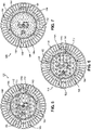
FIG. 5 illustrates a front plan view of the light system ofFIG. 1 depicting an LED configuration adapted for generating a Type I optic pattern; -
FIG. 6 illustrates a front plan view of the light system ofFIG. 1 depicting an LED configuration adapted for generating a Type III optic pattern; -
FIG. 7 illustrates a front plan view of the light system ofFIG. 1 depicting an LED configuration adapted for generating a Type V optic pattern; -
FIG. 8 illustrates a front plan view of a retainer ring of the LED system shown inFIG. 3 ; -
FIG. 9 illustrates a back plan view of the retainer ring ofFIG. 8 ; -
FIG. 10 illustrates a cross-sectional view of the retainer ring ofFIG. 8 ; -
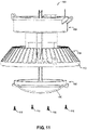
FIG. 11 illustrates a partial exploded view of the light system ofFIG. 1 showing the LED system exploded from a heat sink adapter housing; -
FIG. 12 illustrates a partial enlarged front view of the heat sink adapter housing prior to mounting the LED system thereon; -
FIG. 13 illustrates an exploded view of an alternative LED system in accordance with the principles of the present disclosure; -
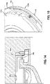
FIG. 14 illustrates a cross-sectional view of the LED system ofFIG. 13 ; and -
FIG. 15 illustrates a partial view showing a retainer ring and baseplate of the LED system ofFIG. 13 . - Reference will now be made in detail to the exemplary aspects of the present disclosure that are illustrated in the accompanying drawings. Wherever possible, the same reference numbers will be used throughout the drawings to refer to the same or like structure.
-
FIGS. 1-2 illustrate anexample light system 100. Thelight system 100 includes adriver compartment 102, a heat sink adapter housing 104 (e.g., housing), and a LED system 106 (e.g., light engine). Thedriver compartment 102 is configured to house a driver assembly (not shown) that can include a power supply and enable operation thereof. In certain examples, thelight system 100 can be mounted to a ceiling, a wall, or other structure via a mounting bracket (not shown) secured to thedriver compartment 102. It will be appreciated that thelight system 100 includes a front side configured to face away from a wall or ceiling to which thelight system 100 mounts, and a back side configured to face toward the wall or ceiling to which thelight system 100 mounts. - The heat
sink adapter housing 104 can be coupled to thedriver compartment 102 to be fixed thereto. The heatsink adapter housing 104 includes a plurality of parallel-oriented fins 108 that are integrally formed with abase 110 to ensure good thermal conductivity. Any heat generated by theLED system 106 can be drawn into the heatsink adapter housing 104 to dissipate the heat. That is, the heatsink adapter housing 104 acts as a heat spreader (thermally conductive) to distribute heat and to provide a relatively large surface area for allowing heat to be transferred to the surrounding air. The heatsink adapter housing 104 may be made of aluminum, brass, copper, polymer steel, or any other material that is thermally conductive. Thebase 110 of the heatsink adapter housing 104 has afront surface 112 that provides amounting platform 114 for theLED system 106. TheLED system 106 can be removably mounted to thefront surface 112 of the heatsink adapter housing 104 by one or more fasteners 116 (seeFIG. 11 ). - Turning to
FIG. 3 , an exploded view of theLED system 106 is shown. TheLED system 106 can include abaseplate 118, aretainer ring 120, and aLED sub-assembly 122. TheLED sub-assembly 122 can include a printed circuit board assembly (PCBA) 124 and optics 126. The optics 126 can include one or more light emitting diodes (LEDs) 128 coupled to asubstrate 130. The PCBA 124 can provide the necessary electrical connections to the optics 126 and other electrical components of thelight system 100. - The
baseplate 118 includes anouter surface 132 that may be covered by athermal pad 134. Adhesive on thethermal pad 134 glues thethermal pad 134 to theoutside surface 132 of thebaseplate 118. The optics 126 and the PCBA 124 can be fastened together to thebaseplate 118 with a plurality ofscrews 136 to fix the optics 126 relative within theLED system 106. - A
first gasket 138 may be disposed in agroove 140 in theouter surface 132 of thebaseplate 118. Thefirst gasket 138 may be pressed into thegroove 140 to create an environmental seal with a back side of anouter flange 145 of aprotective lens 146 when theretainer ring 120 is attached to thebaseplate 118. Theretainer ring 120 can be attached to thebaseplate 118 via one ormore screws 144 with asecond gasket 142 located between theretainer ring 120 and a front side of theouter flange 145 of thelens 146. The first andsecond gaskets FIG. 3A that provides suitable ingress protection against solids and liquids (i.e., intrusion of dust, dirt, accidental contact, and water) into a compartment defined by theprotective lens 146. - As indicated above, the
LED system 106 may also include thelens 146 having an outer flange disposed (e.g., clamped) between thebaseplate 118 and theretainer ring 120. Thelens 146 may at least partially surround the optics 126 and thePCBA 124 and enclose them on thebaseplate 118. Thelens 146 may be made of any at least partially transparent or translucent material, including glass and hard plastics, so as to enable light to be emitted from thelight system 100. Thelens 146 may also provide a protective barrier for the optics 126 and shield the optics 126 from moisture or inclement weather. Theretainer ring 120 is configured to secure together all the components of theLED system 106. The one ormore screws 144 mount theretainer ring 120 to thebaseplate 118 to form theLED system 106 as a fixed unit. - In operation, the optics 126 can emit light so that the
light system 100 can illuminate a required or desired area. The light emitted from the optics 126 can be distributed in predetermined orientations and patterns for the desired illuminated area. That is, thelight system 100 may be configured for a specific light distribution profile to project a predetermined pattern of light onto a surface (e.g., a walkway, roadway). - Referring to
FIG.4 , one classification system that is used to describe the pattern of the illuminated area by thelight system 100 is established by the Illumination Engineering Society of North American (IESNA). IESNA Type I beam pattern has a long and rectangular pattern that is used when thelight system 100 is placed near the center of a pathway and provides lighting for narrower paths or roadways. IESNA Type III beam pattern has a bent pattern that is used when thelight system 100 is placed towards one side of a pathway and provides lighting that projects more outward. IESNA Type V beam pattern has a regular circular pattern that is used for large buildings, warehouses, processing mills, and industrial plants.FIGS. 5-7 show the example IESNA Type I, III,V optics 126a-c that can be used in thelight system 100. - Referring to
FIGS. 8-10 , illustrates multiple views of theretainer ring 120. Theretainer ring 120 includes four equally spaced mountingregions 148 around anouter periphery 150 of theretainer ring 120. Theretainer ring 120 can rotate about a central axis X of thelight system 100. The mountingregions 148 can allow adjustable rotation of theretainer ring 120 by at least 180 degrees to change the light distribution illumination direction of thelight system 100. In certain examples, theretainer ring 120 can be rotated between 45 degrees and 300 degrees to change the light distribution of thelight system 100. - The mounting
regions 148 of theretainer ring 120 can be used to attach theLED system 106 to thefront surface 112 of the heatsink adapter housing 104 via the one ormore screws 116. Thescrews 116 may be fitted into screw holes 152 (e.g., internally threaded holes, openings, seeFIGS. 5-7 ) on thefront surface 112 of the heatsink adapter housing 104. In certain examples, theretainer ring 120 may be shaped and sized to engage a cavity 154 (seeFIG. 3 ) defined in the heatsink adapter housing 104 when theLED system 106 is attached thereto. - The mounting
regions 148 can each include a plurality ofdiscrete openings 156, although alternatives are possible. The plurality ofdiscrete openings 156 are spaced apart equally in an arcuate array and are located near theouter periphery 150 of theretainer ring 120. In certain examples, the mountingregions 148 can each include a slot opening 154 (seeFIG. 15 ). The mountingregions 148 are diametrically positioned about theretainer ring 120 and are identical to each other. Thus, only one mountingregion 148 will be described in detail or referred to. Each of the mountingregions 148 can correspond to acircumferential flange segment 149. Thecircumferential flange segments 149 can be separated byprojections 151. In one example, the plurality ofdiscrete openings 156 are not internally threaded and are slightly oversized with respect to the shanks of thefasteners 116. - The
front surface 112 of the heatsink adapter housing 104 defines at least fourscrew holes 152 that are equally spaced about the heatsink adapter housing 104. The screw holes 152 can each be aligned with a corresponding one of the plurality of parallel-orientedfins 108 of the heatsink adapter housing 104. For example, the fourscrew holes 152 can be defined in a respective one of the plurality of parallel-orientedfins 108. In certain examples, eachscrew hole 152 corresponds to one of the mountingregions 148. - In certain examples, there are at least six
openings 156 per mountinglocation 148 for each of the screw holes 152 of the heatsink adapter housing 104. In certain examples, there are at least sevenopenings 156 per mountinglocation 148 for each of the screw holes 152 of the heatsink adapter housing 104. In certain examples, there are at least eightopenings 156 at each mountinglocation 148 for each of the screw holes 152 of the heatsink adapter housing 104. In certain examples, there are at least nineopenings 156 at each mountinglocation 148 for each of the screw holes 152 of the heatsink adapter housing 104. In certain examples, there are at least tenopenings 156 at each mountinglocation 148 for each of the screw holes 152 of the heatsink adapter housing 104. - Although the mounting
regions 148 are shown on theretainer ring 120 and the screw holes 152 are defined by the heatsink adapter housing 104, the reverse could be provided. That is, the mountingregions 148 can be defined by the heatsink adapter housing 104 and the screw holes 152 can be defined by theretainer ring 120. - Referring to
FIG. 12 , when theLED system 106 is mounted to the heatsink adapter housing 104, one of the plurality ofdiscrete openings 156 of theretainer ring 120 can be respectively aligned with one of the screw holes 152 of the heatsink adapter housing 104. To secure theLED system 106 to the heatsink adapter housing 104, one of thefasteners 116 can be inserted axially through one of the plurality ofdiscrete openings 156 and threaded into the screw holes 152 of the heatsink adapter housing 104. This engagement prevents any movement of theLED system 106 relative to the heatsink adapter housing 104. - Because luminaires are generally placed alongside walkways or conveyer locations where light distribution may not be fully utilized with respect to a road, "clocking" mechanisms can be provided to give a customer flexibility to adjust the light distribution to provide illumination in a desired direction, orientation, or level.
- The
retainer ring 120 may be configured to alter or otherwise modify the light emitted by the optics 126. When a customer desires to "clock" a luminaire or adjust the lighting path or pattern of the optics 126 of thelight system 100, theLED system 106 may be rotated relative to the heatsink adapter housing 104. The amount of rotation needed to achieve a desired light distribution can be determined by using theretainer ring 120. Rotating theretainer ring 120 also rotates thebaseplate 118, thePCBA 124, and the optics 126 of theLED system 106. Because the optics 126 can rotate with theretainer ring 120, the illumination direction of the light emitting pattern of thelight system 100 can be adjusted. - To adjust the illumination direction of the
light system 100, thefasteners 116 are first completely removed from a respective one of the plurality ofdiscrete openings 156 of theretainer ring 120 and thescrew hole 152 of the heatsink adapter housing 104. This allows theLED system 106 to be removed from the heatsink adapter housing 104 to allow theLED system 106 to be rotated relative to the heatsink adapter housing 104 to adjust the clock face position and thus the direction of illumination of thelight system 100. The plurality ofdiscrete openings 156 of theretainer ring 120 allow theLED system 106 to be moved in discrete increments to achieve a desired light distribution in the field that can yield optimal performance. For example, the plurality ofdiscrete openings 156 of theretainer ring 120 can be rotated in a clockwise or counterclockwise direction relative to thescrew hole 152 of the heatsink adapter housing 104 to change the light distribution illumination direction by increments of the plurality ofdiscrete openings 156. That is, the direction in which light distribution of thelight system 100 shines can be adjusted as theretainer ring 120 of theLED system 106 is rotated such that a different one of the plurality ofdiscrete openings 156 of theretainer ring 120 can be aligned to thescrew hole 152 of the heatsink adapter housing 104. - Turning again to
FIG. 8 , the plurality ofdiscrete openings 156 may be spaced no more than 10 degrees apart with respect to the central axis X of thelight system 100. In certain examples, the plurality ofdiscrete openings 156 may be spaced no more than 9 degrees apart with respect to the central axis X of thelight system 100. In certain examples, the plurality ofdiscrete openings 156 may be spaced no more than 8 degrees apart with respect to the central axis X of thelight system 100. As such, the light distribution illumination direction can be change by relatively small increments (e.g., increments less than or equal to about 10, 9, or 8 degrees). - After the desired adjustment is made, the
fasteners 116 can be reinserted through the selected one of the plurality ofopenings 156 of theretainer ring 120 and threaded into thescrew hole 152 of the heatsink adapter housing 104. This process of "clocking" allows for easy adjustment of luminaires in the field without having to remove the one ormore screws 144 that seal theLED system 106. Thescrews 144 keep theLED system 106 fastened and sealed such that theLED system 106 is not loosened or broken open to give risk to any ingress protection. - Referring to
FIGS. 13-15 , analternative LED system 106a is depicted in accordance with the principles of the present disclosure. To the extent that the embodiments are similar, the description will not be repeated and will instead be directed to the primary differences. Specifically, theLED system 106a differs in how theretainer ring 120a mounts to thebaseplate 118a. For example,adhesive tape 158 can be used to secure theretainer ring 120a and thebaseplate 118a together. As such, there is a reduction in parts as thescrews 144 are replaced by theadhesive tape 158. Theadhesive tape 158 can be a double-sided adhesive film. In certain examples, theadhesive tape 158 can have a tensile load capacity of 30 to 40 Newtons (N). In certain examples, theadhesive tape 158 preferably has a tensile strength of about 300N to about 350N. - In addition, the
LED system 106a differs from theLED system 106 shown inFIG. 3 in that the mountingregions 148a of theretainer ring 120a include theslot openings 154 versus discrete openings, although it will be appreciated that the discrete openings described above can be used. The fastener 116a can be inserted through the slot opening 154 of theretainer ring 120a and into thescrew hole 152 of the heat sink adapter housing 104a to attach theLED system 106a to the heat sink adapter housing 104a. - The
slot openings 154 defined in theretainer ring 120a allow theLED system 106a to be "clocked" in a desired direction relative to the heat sink adapter housing 104a by loosening, but not removing, the fastener 116a positioned within theslot openings 154 of theretainer ring 120a. The fastener 116a can be backed out of theslot opening 154 so that ¼ inch to ½ inch of thread is showing to allow theLED system 106a to be rotated relative to the heat sink adapter housing 104a up to about 60 degrees to change the light distribution. In certain examples, the "clocking" direction can include at least about 45 degrees of adjustability. - In certain examples, the fasteners 116a can be completely removed from the
slot openings 154 if an adjustment needs to be made that is beyond about 60 degrees. TheLED system 106a can then be adjusted to any desired position. After the light distribution adjustment is complete, the fasteners 116a can then be reinserted through theslot openings 154 of theretainer ring 120a and into thescrew hole 152 of the heat sink adapter housing 104a and tightened therein to again secure theLED system 106a to the heat sink adapter housing 104a. -
-
Aspect 1. A light system comprising:- a driver compartment assembly;
- a heat sink adapter housing fixed to the driver compartment assembly, the heat sink adapter housing defining a plurality of openings that are each internally threaded;
- a light engine adapted to be removably attached to the heat sink adapter housing, the light engine including:
- a baseplate;
- optics coupled to the baseplate;
- a retainer ring removably mounted to the baseplate, the retainer ring including a plurality of mounting regions circumferentially positioned thereabout, wherein the plurality of mounting regions each include a plurality of discrete openings spaced apart equally in an arcuate array, each of the plurality of mounting regions corresponding to a circumferential flange segment of the retainer ring, the circumferential flange segments of the retainer ring being separated by projections, the plurality of discrete openings being defined through the circumferential flange segments, respectively; and
- a lens having an outer flange disposed between the baseplate and the retainer ring, the lens at least partially surrounding the optics to enclose the optics on the baseplate;
- wherein the retainer ring is rotatable relative to the heat sink adapter in discrete increments via the plurality of discrete openings, the plurality of discrete openings of the plurality of mounting regions each respectively corresponding to one of the plurality of openings of the heat sink adapter, wherein the optics rotate with the retainer ring to change the light distribution illumination direction emitted by the optics.
-
Aspect 2. The light system ofaspect 1, wherein the optics includes one or more light emitting diodes coupled to a substrate. -
Aspect 3. The light system ofaspect 1, wherein the plurality of discrete openings are spaced no more than 8 degrees apart with respect to a central axis of the light system. - Aspect 4. The light system of
aspect 1, wherein the plurality of discrete openings are spaced no more than 10 degrees apart with respect to a central axis of the light system. -
Aspect 5. The light system ofaspect 1, wherein the optics include an IESNA Type I beam pattern. -
Aspect 6. The light system ofaspect 1, wherein the optics include an IESNA Type III beam pattern. - Aspect 7. The light system of
aspect 1, wherein the plurality of mounting regions allow adjustable rotation of the retainer ring by at least 180 degrees to change the light distribution illumination direction of the optics. - Aspect 8. The light system of
aspect 1, wherein the plurality of discrete openings include at least eight discrete openings in the mounting region. - Aspect 9. A light engine comprising:
- a baseplate;
- optics coupled to the baseplate;
- a retainer ring being adhesively attached to the baseplate;
- a heat sink adapter housing removably mounted to the retainer ring; and
- a lens having an outer flange disposed between the baseplate and the retainer ring, the lens at least partially surrounding the optics to enclose the optics on the baseplate;
- wherein the retainer ring and the optics are configured to rotate together relative to the heat sink adapter housing to change the light distribution illumination direction emitted by the optics.
-
Aspect 10. The light engine of aspect 9, wherein the retainer ring includes four separate mounting regions circumferentially positioned thereabout, each of the four separate mounting regions corresponding to a circumferential flange segment of the retainer ring, the circumferential flange segments of the retainer ring being separated by projections. - Aspect 11. The light engine of
aspect 10, wherein the four separate mounting regions each include at least five discrete openings. - Aspect 12. The light engine of
aspect 10, wherein the four separate mounting regions each include at least eight discrete openings. - Aspect 13. The light engine of aspect 9, wherein the optics includes one or more light emitting diodes coupled to a substrate.
- Aspect 14. The light engine of
aspect 10, wherein the four separate mounting regions each include a slot opening. - Aspect 15. A light system defining a central axis, the light system comprising:
- a driver compartment assembly;
- a heat sink adapter housing fixed to the driver compartment;
- a light engine adapted to be removably attached to the heat sink adapter housing, the light engine including:
- a baseplate;
- optics coupled to the baseplate;
- a retainer ring removably mounted to the baseplate;
- a lens having an outer flange disposed between the baseplate and the retainer ring, the lens at least partially surrounding the optics to enclose the optics on the baseplate;
- at least one mounting region having at least eight discrete openings separated by no more than 10 degrees with respect to the central axis, the at least one mounting region being defined by one of the retainer ring and the heat sink adapter housing; and
- at least one opening defined by the other one of the retainer ring and the heat sink adapter housing, the at least one opening being internally threaded and corresponding to the at least one mounting region;
- wherein the retainer ring is rotatable relative to the heat sink adapter housing about the central axis, the retainer ring being rotatable in discrete increments via the at least eight discrete openings, the at least eight discrete openings of the at least one mounting region corresponding with the at least one opening, wherein the optics rotate with the retainer ring to change the light distribution illumination direction emitted by the optics.
- Aspect 16. The light system of aspect 15, wherein the retainer ring is adhesively mounted to the baseplate.
- Aspect 17. The light system of aspect 15, wherein the retainer ring is secured to the baseplate via fasteners.
- Aspect 18. The light system of aspect 15, wherein the optics includes one or more light emitting diodes coupled to a substrate.
- Aspect 19. The light system of aspect 15, wherein the light engine includes four mounting regions that each correspond to a circumferential flange segment.
- Aspect 20. The light system of aspect 19, wherein the circumferential flange segments are separated by projections.
- Various modifications and alterations of this disclosure will become apparent to those skilled in the art without departing from the scope and spirit of this disclosure, and it should be understood that the inventive scope of this disclosure is not to be unduly limited to the illustrative embodiments set forth herein.
Claims (15)
- A light system comprising:a driver compartment assembly;a heat sink adapter housing fixed to the driver compartment assembly, the heat sink adapter housing defining a plurality of openings that are each internally threaded;a light engine adapted to be removably attached to the heat sink adapter housing, the light engine including:a baseplate;optics coupled to the baseplate;a retainer ring removably mounted to the baseplate, the retainer ring including a plurality of mounting regions circumferentially positioned thereabout, wherein the plurality of mounting regions each include a plurality of discrete openings spaced apart equally in an arcuate array, each of the plurality of mounting regions corresponding to a circumferential flange segment of the retainer ring, the circumferential flange segments of the retainer ring being separated by projections, the plurality of discrete openings being defined through the circumferential flange segments, respectively; anda lens having an outer flange disposed between the baseplate and the retainer ring, the lens at least partially surrounding the optics to enclose the optics on the baseplate;wherein the retainer ring is rotatable relative to the heat sink adapter in discrete increments via the plurality of discrete openings, the plurality of discrete openings of the plurality of mounting regions each respectively corresponding to one of the plurality of openings of the heat sink adapter, wherein the optics rotate with the retainer ring to change the light distribution illumination direction emitted by the optics.
- The light system of claim 1, wherein the optics includes one or more light emitting diodes coupled to a substrate.
- The light system of claim 1, wherein the plurality of discrete openings are spaced no more than 8 degrees apart or 10 degrees apart with respect to a central axis of the light system.
- The light system of claim 1, wherein the optics include an IESNA Type I beam pattern or an IESNA Type III beam pattern.
- The light system of claim 1, wherein the plurality of mounting regions allow adjustable rotation of the retainer ring by at least 180 degrees to change the light distribution illumination direction of the optics.
- The light system of claim 1, wherein the plurality of discrete openings include at least eight discrete openings in the mounting region.
- A light engine comprising:a baseplate;optics coupled to the baseplate;a retainer ring being adhesively attached to the baseplate;a heat sink adapter housing removably mounted to the retainer ring; anda lens having an outer flange disposed between the baseplate and the retainer ring, the lens at least partially surrounding the optics to enclose the optics on the baseplate;wherein the retainer ring and the optics are configured to rotate together relative to the heat sink adapter housing to change the light distribution illumination direction emitted by the optics.
- The light engine of claim 7, wherein the retainer ring includes four separate mounting regions circumferentially positioned thereabout, each of the four separate mounting regions corresponding to a circumferential flange segment of the retainer ring, the circumferential flange segments of the retainer ring being separated by projections.
- The light engine of claim 8, wherein the four separate mounting regions each include at least five discrete openings.
- The light engine of claim 7, wherein the optics includes one or more light emitting diodes coupled to a substrate.
- The light engine of claim 8, wherein the four separate mounting regions each include a slot opening.
- A light system defining a central axis, the light system comprising:a driver compartment assembly;a heat sink adapter housing fixed to the driver compartment;a light engine adapted to be removably attached to the heat sink adapter housing, the light engine including:a baseplate;optics coupled to the baseplate;a retainer ring removably mounted to the baseplate;a lens having an outer flange disposed between the baseplate and the retainer ring, the lens at least partially surrounding the optics to enclose the optics on the baseplate;at least one mounting region having at least eight discrete openings separated by no more than 10 degrees with respect to a central axis, the at least one mounting region being defined by one of the retainer ring and the heat sink adapter housing; andat least one opening defined by the other one of the retainer ring and the heat sink adapter housing, the at least one opening being internally threaded and corresponding to the at least one mounting region;wherein the retainer ring is rotatable relative to the heat sink adapter housing about the central axis, the retainer ring being rotatable in discrete increments via the at least eight discrete openings, the at least eight discrete openings of the at least one mounting region corresponding with the at least one opening, wherein the optics rotate with the retainer ring to change the light distribution illumination direction emitted by the optics.
- The light system of claim 12, wherein the retainer ring is secured to the baseplate via fasteners or adhesive.
- The light system of claim 12, wherein the optics includes one or more light emitting diodes coupled to a substrate.
- The light system of claim 12, wherein the light engine includes four mounting regions that each correspond to a circumferential flange segment and wherein the circumferential flange segments are separated by projections.
Applications Claiming Priority (1)
| Application Number | Priority Date | Filing Date | Title |
|---|---|---|---|
| IN202111006819 | 2021-02-18 |
Publications (2)
| Publication Number | Publication Date |
|---|---|
| EP4047264A1 true EP4047264A1 (en) | 2022-08-24 |
| EP4047264B1 EP4047264B1 (en) | 2025-07-02 |
Family
ID=80775217
Family Applications (1)
| Application Number | Title | Priority Date | Filing Date |
|---|---|---|---|
| EP22157547.5A Active EP4047264B1 (en) | 2021-02-18 | 2022-02-18 | Optics clocking for luminaries |
Country Status (5)
| Country | Link |
|---|---|
| US (1) | US11898735B2 (en) |
| EP (1) | EP4047264B1 (en) |
| CN (1) | CN114963046B (en) |
| CA (1) | CA3149334A1 (en) |
| MX (1) | MX2022002036A (en) |
Citations (4)
| Publication number | Priority date | Publication date | Assignee | Title |
|---|---|---|---|---|
| US20070109813A1 (en) * | 2005-11-15 | 2007-05-17 | American Tack & Hardware Co., Inc. | Directionally controllable night light |
| US20160084481A1 (en) * | 2014-09-24 | 2016-03-24 | Hubbell Incorporated | Rotatable single piece optical array |
| US20170205050A1 (en) * | 2016-01-19 | 2017-07-20 | Hubbell Incorporated | Light fixture with pivotable optic |
| IT201900003265A1 (en) * | 2019-03-06 | 2020-09-06 | Iguzzini Illuminazione | MODULAR STRUCTURE LIGHTING APPLIANCE |
Family Cites Families (19)
| Publication number | Priority date | Publication date | Assignee | Title |
|---|---|---|---|---|
| JP4070625B2 (en) * | 2003-02-07 | 2008-04-02 | 日本放送協会 | Light emitting diode floodlight device |
| JP4207931B2 (en) * | 2005-07-25 | 2009-01-14 | パナソニック電工株式会社 | lighting equipment |
| JP2007149552A (en) * | 2005-11-29 | 2007-06-14 | Harison Toshiba Lighting Corp | Lighting device |
| CA2630477C (en) * | 2007-05-04 | 2010-12-14 | Abl Ip Holding Llc | Adjustable light distribution system |
| DE102009006420A1 (en) * | 2009-01-28 | 2010-12-09 | Osram Gesellschaft mit beschränkter Haftung | LED lamp, socket and method for operating an LED lamp |
| CN102168831B (en) | 2011-03-22 | 2014-04-02 | 王剑波 | Low-position acute angle road illuminating lamp and illuminating and installation method thereof |
| CN102141223A (en) | 2011-04-26 | 2011-08-03 | 雍徽 | High-power LED (Light Emitting Diode) light source assembled street lamp and tunnel lamp |
| CN202109351U (en) | 2011-05-12 | 2012-01-11 | 兆光科技有限公司 | LED street light with level and angle adjustment |
| US9234645B2 (en) * | 2011-07-06 | 2016-01-12 | Lg Innotek Co., Ltd. | Lighting device having adjustable reflector |
| CN104421897B (en) * | 2013-09-06 | 2020-09-04 | 深圳市海洋王照明工程有限公司 | Lamp set |
| CN205174189U (en) * | 2015-11-24 | 2016-04-20 | 广州市佛达信号设备有限公司 | LED (light emitting diode) signal lamp |
| CN205664212U (en) * | 2016-06-02 | 2016-10-26 | 佛山熙元照明科技有限公司 | Can dismantle free rotation LED lamps and lanterns |
| KR101801181B1 (en) * | 2017-06-29 | 2017-11-27 | 디비라이텍 주식회사 | Lighting device with variable light distribution |
| JP3216147U (en) * | 2018-02-26 | 2018-05-17 | シク オ,ギル | Outdoor light with a choice of light irradiation direction |
| CN208936113U (en) * | 2018-09-03 | 2019-06-04 | 上海亚明照明有限公司 | A kind of mounting structure of the multi-direction adjusting of lamps and lanterns |
| CN208919852U (en) * | 2018-10-25 | 2019-05-31 | 深圳市六勤照明科技有限公司 | A kind of bright dress lamp facilitating installation |
| WO2020102996A1 (en) * | 2018-11-20 | 2020-05-28 | 厦门三安光电有限公司 | Adjustable-focus illumination apparatus |
| US11236887B2 (en) * | 2019-01-25 | 2022-02-01 | Eaton Intelligent Power Limited | Optical structures for light emitting diodes (LEDs) |
| CN211176493U (en) * | 2020-01-22 | 2020-08-04 | 伊顿智能动力有限公司 | Explosion-proof lamp |
-
2022
- 2022-02-17 US US17/674,311 patent/US11898735B2/en active Active
- 2022-02-17 CA CA3149334A patent/CA3149334A1/en active Pending
- 2022-02-17 MX MX2022002036A patent/MX2022002036A/en unknown
- 2022-02-18 EP EP22157547.5A patent/EP4047264B1/en active Active
- 2022-02-18 CN CN202210150140.1A patent/CN114963046B/en active Active
Patent Citations (4)
| Publication number | Priority date | Publication date | Assignee | Title |
|---|---|---|---|---|
| US20070109813A1 (en) * | 2005-11-15 | 2007-05-17 | American Tack & Hardware Co., Inc. | Directionally controllable night light |
| US20160084481A1 (en) * | 2014-09-24 | 2016-03-24 | Hubbell Incorporated | Rotatable single piece optical array |
| US20170205050A1 (en) * | 2016-01-19 | 2017-07-20 | Hubbell Incorporated | Light fixture with pivotable optic |
| IT201900003265A1 (en) * | 2019-03-06 | 2020-09-06 | Iguzzini Illuminazione | MODULAR STRUCTURE LIGHTING APPLIANCE |
Also Published As
| Publication number | Publication date |
|---|---|
| US11898735B2 (en) | 2024-02-13 |
| CN114963046B (en) | 2025-06-10 |
| CA3149334A1 (en) | 2022-08-18 |
| US20220260242A1 (en) | 2022-08-18 |
| MX2022002036A (en) | 2022-08-19 |
| CN114963046A (en) | 2022-08-30 |
| EP4047264B1 (en) | 2025-07-02 |
Similar Documents
| Publication | Publication Date | Title |
|---|---|---|
| US10460634B2 (en) | LED light assembly with transparent substrate having array of lenses for projecting light to illuminate an area | |
| US7237924B2 (en) | LED signal lamp | |
| US7997768B2 (en) | LED lamp | |
| US9016896B1 (en) | Obstruction lighting system | |
| US9068738B2 (en) | Structure for protecting LED light source from moisture | |
| US8870413B2 (en) | Optical panel for LED light source | |
| JP2011014316A (en) | Lighting device | |
| EP4047264B1 (en) | Optics clocking for luminaries |
Legal Events
| Date | Code | Title | Description |
|---|---|---|---|
| PUAI | Public reference made under article 153(3) epc to a published international application that has entered the european phase |
Free format text: ORIGINAL CODE: 0009012 |
|
| STAA | Information on the status of an ep patent application or granted ep patent |
Free format text: STATUS: THE APPLICATION HAS BEEN PUBLISHED |
|
| AK | Designated contracting states |
Kind code of ref document: A1 Designated state(s): AL AT BE BG CH CY CZ DE DK EE ES FI FR GB GR HR HU IE IS IT LI LT LU LV MC MK MT NL NO PL PT RO RS SE SI SK SM TR |
|
| STAA | Information on the status of an ep patent application or granted ep patent |
Free format text: STATUS: REQUEST FOR EXAMINATION WAS MADE |
|
| 17P | Request for examination filed |
Effective date: 20230221 |
|
| RBV | Designated contracting states (corrected) |
Designated state(s): AL AT BE BG CH CY CZ DE DK EE ES FI FR GB GR HR HU IE IS IT LI LT LU LV MC MK MT NL NO PL PT RO RS SE SI SK SM TR |
|
| P01 | Opt-out of the competence of the unified patent court (upc) registered |
Effective date: 20230521 |
|
| GRAP | Despatch of communication of intention to grant a patent |
Free format text: ORIGINAL CODE: EPIDOSNIGR1 |
|
| STAA | Information on the status of an ep patent application or granted ep patent |
Free format text: STATUS: GRANT OF PATENT IS INTENDED |
|
| RIC1 | Information provided on ipc code assigned before grant |
Ipc: F21Y 115/10 20160101ALN20240927BHEP Ipc: F21Y 105/18 20160101ALN20240927BHEP Ipc: F21W 131/10 20060101ALN20240927BHEP Ipc: F21V 29/77 20150101ALI20240927BHEP Ipc: F21V 14/02 20060101AFI20240927BHEP |
|
| INTG | Intention to grant announced |
Effective date: 20241018 |
|
| GRAJ | Information related to disapproval of communication of intention to grant by the applicant or resumption of examination proceedings by the epo deleted |
Free format text: ORIGINAL CODE: EPIDOSDIGR1 |
|
| STAA | Information on the status of an ep patent application or granted ep patent |
Free format text: STATUS: REQUEST FOR EXAMINATION WAS MADE |
|
| GRAP | Despatch of communication of intention to grant a patent |
Free format text: ORIGINAL CODE: EPIDOSNIGR1 |
|
| STAA | Information on the status of an ep patent application or granted ep patent |
Free format text: STATUS: GRANT OF PATENT IS INTENDED |
|
| INTC | Intention to grant announced (deleted) | ||
| RIC1 | Information provided on ipc code assigned before grant |
Ipc: F21Y 115/10 20160101ALN20250122BHEP Ipc: F21Y 105/18 20160101ALN20250122BHEP Ipc: F21W 131/10 20060101ALN20250122BHEP Ipc: F21V 29/77 20150101ALI20250122BHEP Ipc: F21V 14/02 20060101AFI20250122BHEP |
|
| INTG | Intention to grant announced |
Effective date: 20250131 |
|
| GRAS | Grant fee paid |
Free format text: ORIGINAL CODE: EPIDOSNIGR3 |
|
| GRAA | (expected) grant |
Free format text: ORIGINAL CODE: 0009210 |
|
| STAA | Information on the status of an ep patent application or granted ep patent |
Free format text: STATUS: THE PATENT HAS BEEN GRANTED |
|
| AK | Designated contracting states |
Kind code of ref document: B1 Designated state(s): AL AT BE BG CH CY CZ DE DK EE ES FI FR GB GR HR HU IE IS IT LI LT LU LV MC MK MT NL NO PL PT RO RS SE SI SK SM TR |
|
| REG | Reference to a national code |
Ref country code: GB Ref legal event code: FG4D |
|
| REG | Reference to a national code |
Ref country code: CH Ref legal event code: EP |
|
| REG | Reference to a national code |
Ref country code: DE Ref legal event code: R096 Ref document number: 602022016659 Country of ref document: DE |
|
| REG | Reference to a national code |
Ref country code: IE Ref legal event code: FG4D |
|
| REG | Reference to a national code |
Ref country code: NL Ref legal event code: FP |
|
| PG25 | Lapsed in a contracting state [announced via postgrant information from national office to epo] |
Ref country code: PT Free format text: LAPSE BECAUSE OF FAILURE TO SUBMIT A TRANSLATION OF THE DESCRIPTION OR TO PAY THE FEE WITHIN THE PRESCRIBED TIME-LIMIT Effective date: 20251103 |
|
| REG | Reference to a national code |
Ref country code: AT Ref legal event code: MK05 Ref document number: 1809589 Country of ref document: AT Kind code of ref document: T Effective date: 20250702 |
|
| PG25 | Lapsed in a contracting state [announced via postgrant information from national office to epo] |
Ref country code: IS Free format text: LAPSE BECAUSE OF FAILURE TO SUBMIT A TRANSLATION OF THE DESCRIPTION OR TO PAY THE FEE WITHIN THE PRESCRIBED TIME-LIMIT Effective date: 20251102 |
|
| PG25 | Lapsed in a contracting state [announced via postgrant information from national office to epo] |
Ref country code: NO Free format text: LAPSE BECAUSE OF FAILURE TO SUBMIT A TRANSLATION OF THE DESCRIPTION OR TO PAY THE FEE WITHIN THE PRESCRIBED TIME-LIMIT Effective date: 20251002 |
|
| REG | Reference to a national code |
Ref country code: LT Ref legal event code: MG9D |
|
| PG25 | Lapsed in a contracting state [announced via postgrant information from national office to epo] |
Ref country code: AT Free format text: LAPSE BECAUSE OF FAILURE TO SUBMIT A TRANSLATION OF THE DESCRIPTION OR TO PAY THE FEE WITHIN THE PRESCRIBED TIME-LIMIT Effective date: 20250702 |
|
| PG25 | Lapsed in a contracting state [announced via postgrant information from national office to epo] |
Ref country code: FI Free format text: LAPSE BECAUSE OF FAILURE TO SUBMIT A TRANSLATION OF THE DESCRIPTION OR TO PAY THE FEE WITHIN THE PRESCRIBED TIME-LIMIT Effective date: 20250702 |
|
| PG25 | Lapsed in a contracting state [announced via postgrant information from national office to epo] |
Ref country code: HR Free format text: LAPSE BECAUSE OF FAILURE TO SUBMIT A TRANSLATION OF THE DESCRIPTION OR TO PAY THE FEE WITHIN THE PRESCRIBED TIME-LIMIT Effective date: 20250702 |
|
| PG25 | Lapsed in a contracting state [announced via postgrant information from national office to epo] |
Ref country code: GR Free format text: LAPSE BECAUSE OF FAILURE TO SUBMIT A TRANSLATION OF THE DESCRIPTION OR TO PAY THE FEE WITHIN THE PRESCRIBED TIME-LIMIT Effective date: 20251003 |
|
| PG25 | Lapsed in a contracting state [announced via postgrant information from national office to epo] |
Ref country code: SE Free format text: LAPSE BECAUSE OF FAILURE TO SUBMIT A TRANSLATION OF THE DESCRIPTION OR TO PAY THE FEE WITHIN THE PRESCRIBED TIME-LIMIT Effective date: 20250702 Ref country code: CZ Free format text: LAPSE BECAUSE OF FAILURE TO SUBMIT A TRANSLATION OF THE DESCRIPTION OR TO PAY THE FEE WITHIN THE PRESCRIBED TIME-LIMIT Effective date: 20250702 |
|
| PG25 | Lapsed in a contracting state [announced via postgrant information from national office to epo] |
Ref country code: LV Free format text: LAPSE BECAUSE OF FAILURE TO SUBMIT A TRANSLATION OF THE DESCRIPTION OR TO PAY THE FEE WITHIN THE PRESCRIBED TIME-LIMIT Effective date: 20250702 |
|
| PG25 | Lapsed in a contracting state [announced via postgrant information from national office to epo] |
Ref country code: BG Free format text: LAPSE BECAUSE OF FAILURE TO SUBMIT A TRANSLATION OF THE DESCRIPTION OR TO PAY THE FEE WITHIN THE PRESCRIBED TIME-LIMIT Effective date: 20250702 Ref country code: PL Free format text: LAPSE BECAUSE OF FAILURE TO SUBMIT A TRANSLATION OF THE DESCRIPTION OR TO PAY THE FEE WITHIN THE PRESCRIBED TIME-LIMIT Effective date: 20250702 |
|
| PG25 | Lapsed in a contracting state [announced via postgrant information from national office to epo] |
Ref country code: RS Free format text: LAPSE BECAUSE OF FAILURE TO SUBMIT A TRANSLATION OF THE DESCRIPTION OR TO PAY THE FEE WITHIN THE PRESCRIBED TIME-LIMIT Effective date: 20251002 |
|
| PG25 | Lapsed in a contracting state [announced via postgrant information from national office to epo] |
Ref country code: ES Free format text: LAPSE BECAUSE OF FAILURE TO SUBMIT A TRANSLATION OF THE DESCRIPTION OR TO PAY THE FEE WITHIN THE PRESCRIBED TIME-LIMIT Effective date: 20250702 |
|
| PGFP | Annual fee paid to national office [announced via postgrant information from national office to epo] |
Ref country code: NL Payment date: 20260121 Year of fee payment: 5 |
|
| PG25 | Lapsed in a contracting state [announced via postgrant information from national office to epo] |
Ref country code: SM Free format text: LAPSE BECAUSE OF FAILURE TO SUBMIT A TRANSLATION OF THE DESCRIPTION OR TO PAY THE FEE WITHIN THE PRESCRIBED TIME-LIMIT Effective date: 20250702 |
|
| PGFP | Annual fee paid to national office [announced via postgrant information from national office to epo] |
Ref country code: GB Payment date: 20260121 Year of fee payment: 5 |
|
| PG25 | Lapsed in a contracting state [announced via postgrant information from national office to epo] |
Ref country code: DK Free format text: LAPSE BECAUSE OF FAILURE TO SUBMIT A TRANSLATION OF THE DESCRIPTION OR TO PAY THE FEE WITHIN THE PRESCRIBED TIME-LIMIT Effective date: 20250702 |
|
| PGFP | Annual fee paid to national office [announced via postgrant information from national office to epo] |
Ref country code: DE Payment date: 20260121 Year of fee payment: 5 |
|
| PGFP | Annual fee paid to national office [announced via postgrant information from national office to epo] |
Ref country code: IT Payment date: 20260121 Year of fee payment: 5 |
|
| PGFP | Annual fee paid to national office [announced via postgrant information from national office to epo] |
Ref country code: FR Payment date: 20260121 Year of fee payment: 5 |
|
| PG25 | Lapsed in a contracting state [announced via postgrant information from national office to epo] |
Ref country code: EE Free format text: LAPSE BECAUSE OF FAILURE TO SUBMIT A TRANSLATION OF THE DESCRIPTION OR TO PAY THE FEE WITHIN THE PRESCRIBED TIME-LIMIT Effective date: 20250702 Ref country code: SK Free format text: LAPSE BECAUSE OF FAILURE TO SUBMIT A TRANSLATION OF THE DESCRIPTION OR TO PAY THE FEE WITHIN THE PRESCRIBED TIME-LIMIT Effective date: 20250702 |
|
| PLBE | No opposition filed within time limit |
Free format text: ORIGINAL CODE: 0009261 |
|
| STAA | Information on the status of an ep patent application or granted ep patent |
Free format text: STATUS: NO OPPOSITION FILED WITHIN TIME LIMIT |