EP4047215A1 - Fan speed regulation system and method - Google Patents
Fan speed regulation system and method Download PDFInfo
- Publication number
- EP4047215A1 EP4047215A1 EP20879057.6A EP20879057A EP4047215A1 EP 4047215 A1 EP4047215 A1 EP 4047215A1 EP 20879057 A EP20879057 A EP 20879057A EP 4047215 A1 EP4047215 A1 EP 4047215A1
- Authority
- EP
- European Patent Office
- Prior art keywords
- fan
- rotational speed
- temperature information
- speed regulation
- board
- Prior art date
- Legal status (The legal status is an assumption and is not a legal conclusion. Google has not performed a legal analysis and makes no representation as to the accuracy of the status listed.)
- Granted
Links
Images




Classifications
-
- F—MECHANICAL ENGINEERING; LIGHTING; HEATING; WEAPONS; BLASTING
- F04—POSITIVE - DISPLACEMENT MACHINES FOR LIQUIDS; PUMPS FOR LIQUIDS OR ELASTIC FLUIDS
- F04D—NON-POSITIVE-DISPLACEMENT PUMPS
- F04D25/00—Pumping installations or systems
- F04D25/16—Combinations of two or more pumps ; Producing two or more separate gas flows
- F04D25/166—Combinations of two or more pumps ; Producing two or more separate gas flows using fans
-
- F—MECHANICAL ENGINEERING; LIGHTING; HEATING; WEAPONS; BLASTING
- F04—POSITIVE - DISPLACEMENT MACHINES FOR LIQUIDS; PUMPS FOR LIQUIDS OR ELASTIC FLUIDS
- F04D—NON-POSITIVE-DISPLACEMENT PUMPS
- F04D27/00—Control, e.g. regulation, of pumps, pumping installations or pumping systems specially adapted for elastic fluids
- F04D27/001—Testing thereof; Determination or simulation of flow characteristics; Stall or surge detection, e.g. condition monitoring
-
- F—MECHANICAL ENGINEERING; LIGHTING; HEATING; WEAPONS; BLASTING
- F04—POSITIVE - DISPLACEMENT MACHINES FOR LIQUIDS; PUMPS FOR LIQUIDS OR ELASTIC FLUIDS
- F04D—NON-POSITIVE-DISPLACEMENT PUMPS
- F04D27/00—Control, e.g. regulation, of pumps, pumping installations or pumping systems specially adapted for elastic fluids
- F04D27/004—Control, e.g. regulation, of pumps, pumping installations or pumping systems specially adapted for elastic fluids by varying driving speed
-
- F—MECHANICAL ENGINEERING; LIGHTING; HEATING; WEAPONS; BLASTING
- F04—POSITIVE - DISPLACEMENT MACHINES FOR LIQUIDS; PUMPS FOR LIQUIDS OR ELASTIC FLUIDS
- F04D—NON-POSITIVE-DISPLACEMENT PUMPS
- F04D27/00—Control, e.g. regulation, of pumps, pumping installations or pumping systems specially adapted for elastic fluids
- F04D27/008—Stop safety or alarm devices, e.g. stop-and-go control; Disposition of check-valves
-
- G—PHYSICS
- G06—COMPUTING OR CALCULATING; COUNTING
- G06F—ELECTRIC DIGITAL DATA PROCESSING
- G06F1/00—Details not covered by groups G06F3/00 - G06F13/00 and G06F21/00
- G06F1/16—Constructional details or arrangements
- G06F1/20—Cooling means
-
- G—PHYSICS
- G06—COMPUTING OR CALCULATING; COUNTING
- G06F—ELECTRIC DIGITAL DATA PROCESSING
- G06F1/00—Details not covered by groups G06F3/00 - G06F13/00 and G06F21/00
- G06F1/16—Constructional details or arrangements
- G06F1/20—Cooling means
- G06F1/206—Cooling means comprising thermal management
-
- G—PHYSICS
- G06—COMPUTING OR CALCULATING; COUNTING
- G06F—ELECTRIC DIGITAL DATA PROCESSING
- G06F1/00—Details not covered by groups G06F3/00 - G06F13/00 and G06F21/00
- G06F1/26—Power supply means, e.g. regulation thereof
- G06F1/32—Means for saving power
- G06F1/3203—Power management, i.e. event-based initiation of a power-saving mode
- G06F1/3234—Power saving characterised by the action undertaken
- G06F1/325—Power saving in peripheral device
-
- F—MECHANICAL ENGINEERING; LIGHTING; HEATING; WEAPONS; BLASTING
- F05—INDEXING SCHEMES RELATING TO ENGINES OR PUMPS IN VARIOUS SUBCLASSES OF CLASSES F01-F04
- F05D—INDEXING SCHEME FOR ASPECTS RELATING TO NON-POSITIVE-DISPLACEMENT MACHINES OR ENGINES, GAS-TURBINES OR JET-PROPULSION PLANTS
- F05D2270/00—Control
- F05D2270/30—Control parameters, e.g. input parameters
- F05D2270/303—Temperature
-
- F—MECHANICAL ENGINEERING; LIGHTING; HEATING; WEAPONS; BLASTING
- F05—INDEXING SCHEMES RELATING TO ENGINES OR PUMPS IN VARIOUS SUBCLASSES OF CLASSES F01-F04
- F05D—INDEXING SCHEME FOR ASPECTS RELATING TO NON-POSITIVE-DISPLACEMENT MACHINES OR ENGINES, GAS-TURBINES OR JET-PROPULSION PLANTS
- F05D2270/00—Control
- F05D2270/70—Type of control algorithm
- F05D2270/706—Type of control algorithm proportional-integral-differential
-
- F—MECHANICAL ENGINEERING; LIGHTING; HEATING; WEAPONS; BLASTING
- F05—INDEXING SCHEMES RELATING TO ENGINES OR PUMPS IN VARIOUS SUBCLASSES OF CLASSES F01-F04
- F05D—INDEXING SCHEME FOR ASPECTS RELATING TO NON-POSITIVE-DISPLACEMENT MACHINES OR ENGINES, GAS-TURBINES OR JET-PROPULSION PLANTS
- F05D2270/00—Control
- F05D2270/80—Devices generating input signals, e.g. transducers, sensors, cameras or strain gauges
Definitions
- the present disclosure relates to the field of system heat dissipation technologies for network devices, and in particular to a fan speed regulation system and method.
- a heat dissipation method with zonal speed regulation is mainly adopted.
- a monitoring board acquires the environmental temperature and chip temperature of a line card inside a network device to perform overall speed regulation on fans in corresponding zones in combination with overall environmental temperature.
- An existing heat dissipation method with zonal speed regulation has the following drawbacks: Fans in different zones result in a great deal of control, and as a result, the rotational speed regulation of the fans is not smooth enough; the output power of most of the fans is useless, causing a waste of energy and generating loud noise; and since the monitoring board is required to perform overall control on the fans, if monitoring lines fail, the speed of the fans can no longer be regulated normally.
- the present disclosure provides a fan speed regulation system and method, so as to meet the requirements of network devices on heat dissipation, power consumption and noise.
- an embodiment of the present disclosure provides a fan speed regulation system applied to a network device, including a monitoring board, a signal backplane, at least one temperature sensor array, at least one fan integration board, and at least one fan array.
- the monitoring board, the temperature sensor array, and the fan integration board are communicatively connected to the signal backplane, and the fan integration board is communicatively connected to the fan array.
- the monitoring board or the fan integration board is configured to calculate a rotational speed of the fan array according to temperature information and a preset speed regulation mode and generate corresponding rotational speed control information.
- the rotational speed control information includes a target rotational speed of each fan and a corresponding relationship between a fan and a temperature sensor subarray.
- the signal backplane is configured to transmit information.
- the temperature sensor array is configured to acquire temperature information of single boards in a network device.
- the fan integration board is further configured to regulate the rotational speed of each fan in the fan array according to the rotational speed control information.
- the fan array is configured to dissipate the heat of the network device.
- an embodiment of the present disclosure provides a fan speed regulation method applied to a fan speed regulation system in a network device, including: acquiring, by a temperature sensor array, temperature information of single boards in a network device; obtaining, by a monitoring board or a fan integration board, the temperature information through a signal backplane; calculating, by the monitoring board or the fan integration board, a rotational speed of a fan array according to the temperature information and a preset speed regulation mode, and generating corresponding rotational speed control information, the rotational speed control information including a target rotational speed of each fan and a corresponding relationship between a fan and a temperature sensor subarray; and regulating, by the fan integration board, the rotational speed of each fan in the fan array according to the rotational speed control information.
- an embodiment of the present disclosure provides a network device, including the fan speed regulation system according to the first aspect.
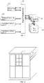
- FIG. 1 is a schematic structural diagram of a fan speed regulation system according to the present disclosure.
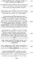
- FIG. 2 is a schematic diagram of a partial architecture of a network device according to the present disclosure. As shown in FIG. 2 , the fan speed regulation system may be integrated in any type of network device, such as a switch device.
- the fan speed regulation system includes a monitoring board 10, a signal backplane 20, at least one temperature sensor array 30, at least one fan integration board 40, and at least one fan array 50.
- the monitoring board 10, the temperature sensor array 30, and the fan integration board 40 are communicatively connected to the signal backplane 20.
- the fan integration board 40 is communicatively connected to the fan array 50.
- the monitoring board 10 or the fan integration board 40 is configured to: calculate a rotational speed of the fan array 50 according to temperature information and a preset speed regulation mode, and generate corresponding rotational speed control information, the rotational speed control information including a target rotational speed of each fan and a corresponding relationship between a fan and a temperature sensor subarray.
- the signal backplane 20 is configured to transmit information.
- the temperature sensor array 30 is configured to acquire temperature information of single boards in a network device.
- the fan integration board 40 is further configured to regulate a rotational speed of each fan in the fan array 50 according to the rotational speed control information.
- the fan array 50 is configured to dissipate heat of the network device.
- the monitoring board 10 is a fan control and management module in the network device, and is mainly configured to: calculate the rotational speed of the fan array 50 according to the temperature information acquired by the temperature sensor array 30 and the preset speed regulation mode, and generate corresponding rotational speed control information.
- the preset speed regulation mode includes, but not limited to, an automatic independent speed regulation mode, an offline independent speed regulation mode, an automatic zonal speed regulation mode or a manual speed regulation mode.
- the monitoring board 10 is required to sequentially obtain temperature information at positions on a single board from the temperature sensor array 30 and a corresponding relationship of specific positions of fans in the fan array 50, so as to dynamically regulate a rotational speed of a fan at a corresponding position, and fans at other unrelated positions are regulated down to an appropriate speed by a speed regulation policy.
- the fan integration board 40 automatically recognizes a corresponding relationship between a fan and the temperature sensor array 30 according to slot information, and directly obtains information about a corresponding temperature sensor to automatically regulate a rotational speed according to the corresponding relationship, regardless of information about other temperature sensors.
- the monitoring board 10 may further monitor electromechanical information (such as voltage or power consumption) of single boards in the network device, and may further carry out functions such as issuing fan control and power-on and -off control.
- the monitoring board 10 may communicate with a master control board in the network device to transmit the electromechanical information.
- the monitoring board 10 may be a dedicated single board or may be a small system possessing the same processing function or part of functional modules in the master control board, which is not limited by the embodiments of the present disclosure.
- the signal backplane 20 is a transmission medium for communication signals, and may be configured to transmit information.
- the signal backplane 20 may be a circuit board, a connector, or a signal transmission medium such as an optical fiber or a network cable.
- the specific structure of the signal backplane is not limited by the embodiments of the present disclosure.
- the signal backplane 20 may transmit electromechanical information between the monitoring board 10 and other single boards, and may further transmit control information between the monitoring board 10 and the fan integration board 40.
- the signal backplane 20 may also obtain a corresponding relationship between a fan and a single board, through different insertion positions on the signal backplane 20.
- the temperature sensor array 30 is a temperature acquisition apparatus on a single board, and may utilize a plurality of temperature sensors to acquire temperature information of different positions and different chips of the single board.
- the temperature sensor array 30 may be a dedicated temperature sensor chip or may be a chip with a temperature measurement function, which is not limited by the embodiments of the present disclosure.
- each single board is provided with a plurality of temperature sensors, forming a plurality of temperature sensor subarrays.
- the temperature sensor subarrays transmit data to the monitoring board 10 or the fan integration board 40 through a data bus.
- the fan array 50 may be a fan group composed of a plurality of fans, and is configured to dissipate the heat of the network device by air suction or air draft.
- the fan array 50 may be a multi-rotor fan formed by putting together a plurality of independent fans, and the number of the fans may be determined by the density of temperature sensors and the volume of each fan.
- the monitoring board 10 may obtain temperature information acquired by all the temperature sensor arrays 30 through the signal backplane 20 and calculate, through the obtained temperature information, a rotational speed that is supposed to be configured for each fan, so as to generate corresponding rotational speed control information and issue the rotational speed control information to the fan integration board 40 through the signal backplane 20, so that the fan integration board 40 can control and drive a rotational speed of the fans according to the received rotational speed control information.
- a separate small control system arranged on the fan integration board 40 can independently obtain the temperature information acquired by the temperature sensor array 30, so as to generate corresponding rotational speed control information and control and drive a rotational speed of the fans, and thus the rotational speed of the fans can be independently controlled and regulated without the monitoring board 10.
- the fan speed regulation system in the present disclosure is configurable to allow the monitoring board, the fan integration board, and the temperature sensor array to cooperate with one another to implement automatic speed regulation on the fan array. Fine-grained monitoring is achieved by the high-density temperature sensor arrays and fan arrays, and the range of action of each fan is controlled at a low level, thereby increasing the efficiency of fan control and reducing the noise level of the fans. Because the number of the fans is large and the range of action of each fan is small, when a single fan fails, the influence on the fan speed regulation system is minimal, and the neighboring fans can also make up for the loss of air volume by the malfunctioning fan.
- the fan speed regulation system can also be automatically switched to the fan integration board to perform temperature detection and fan control, so that the influence caused the failure of part of the devices is minimized, improving the overall reliability.
- the temperature sensor array in the fan speed regulation system acquires temperature information of single boards in the network device
- the monitoring board or the fan integration board calculates the rotational speed of the fan array according to the acquired temperature information and the preset speed regulation mode and generates corresponding rotational speed control information
- the fan integration board regulates a rotational speed of each fan in the fan array according to the rotational speed control information.
- the preset speed regulation mode may adopt the automatic independent speed regulation mode.
- FIG. 4 is a schematic diagram of a hardware topology of a fan speed regulation system according to the present disclosure.
- the monitoring board 10 may set a current speed regulation mode to the automatic independent speed regulation mode and send information about the current speed regulation mode to the fan integration board 40.
- the fan integration board 40 receives the information about the current speed regulation mode and then enters a slave mode. Then, the monitoring board 10 obtains the temperature information through a communication bus of the signal backplane 20, classifies the temperature information, and sets target temperature information of each fan in the fan array 50 according to a classification result.
- the temperature information may include a real-time temperature of a chip and an environmental temperature near the chip.
- the target temperature information of each fan in the fan array 50 may include the corresponding relationship between a fan and a temperature sensor subarray and a target temperature of each fan.
- the monitoring board 10 may calculate the target rotational speed of each fan according to the target temperature information and actual temperature information, then generate rotational speed control information according to the target rotational speed of each fan, and send the rotational speed control information to the fan integration board 40 through the signal backplane 20.
- the monitoring board 10 may determine the corresponding relationship between a fan and a temperature sensor subarray, select available temperatures from the temperature information, and calculate a reference temperature according to the available temperatures.
- the available temperatures include short-term environmental temperature and short-term incoming and outgoing air temperatures.
- the reference temperature is a standard difference between the short-term environmental temperature and the short-term incoming and outgoing air temperatures. Then, the monitoring board 10 sets the target temperature of each fan according to the reference temperature and target noise, and sets target temperature information of each fan in the fan array 50 according to the target temperature of each fan and the corresponding relationship.
- the monitoring board 10 may adopt the target temperature information as an input variable and the actual temperature information as an output variable to calculate a difference between the target temperature information and the actual temperature information as a deviation, and calculate the target rotational speed of each fan according to the preset speed regulation mode, the input variable, the output variable, and the deviation.
- the fan integration board 40 is further configured to: acquire a fedback rotational speed of each fan, and feed back the fedback rotational speed to the monitoring board 10.
- the monitoring board 10 is configured to: determine an operating status of the fan speed regulation system according to the fedback rotational speed of each fan, and give an alarm when determining that the operating status of the fan speed regulation system is an abnormal status.
- the preset speed regulation mode may be the automatic independent speed regulation mode.
- FIG. 5 is a schematic diagram of a hardware topology of a fan speed regulation system according to the present disclosure.
- the monitoring board 10 may set a current speed regulation mode to the automatic independent speed regulation mode, and send information about the current speed regulation mode to the fan integration board 40.
- the fan integration board 40 receives the information about the current speed regulation mode and then enters a master mode, or the fan integration board 40 directly enters a master mode when determining that the number of times of failing to detect the monitoring board 10 exceeds a preset threshold.
- the fan integration board 40 obtains the temperature information through an independent communication bus of the signal backplane 20, classifies the temperature information, and sets target temperature information of each fan in the fan array 50 according to a classification result.
- the temperature information includes a real-time temperature of a chip and an environmental temperature near the chip, and the target temperature information of each fan in the fan array 50 includes the corresponding relationship between a fan and a temperature sensor subarray and a target temperature of each fan.
- the fan integration board 40 may calculate the target rotational speed of each fan according to the target temperature information and actual temperature information, and then generate rotational speed control information according to the target rotational speed of each fan.
- the fan integration board 40 may determine the corresponding relationship between a fan and a temperature sensor subarray, select available temperatures from the temperature information, and calculate a reference temperature according to the available temperatures.
- the available temperatures include short-term environmental temperature and short-term incoming and outgoing air temperatures. Then, the fan integration board 40 sets the target temperature of each fan according to the reference temperature and target noise, and sets target temperature information of each fan in the fan array 50 according to the target temperature of each fan and the corresponding relationship.
- the fan integration board 40 may adopt the target temperature information as an input variable and the actual temperature information as an output variable to calculate a difference between the target temperature information and the actual temperature information as a deviation, and calculate the target rotational speed of each fan according to the preset speed regulation mode, the input variable, the output variable, and the deviation.
- the fan integration board 40 is further configured to: acquire a fedback rotational speed of each fan to determine an operating status of the fan speed regulation system according to the fedback rotational speed of each fan, and give an alarm in a set alarm mode when determining that the operating status of the fan speed regulation system is an abnormal status.
- FIG. 6 is a schematic flowchart of a fan speed regulation method according to the present disclosure. The method is applicable to a case in which speed regulation is performed on a fan for heat dissipation in a network device.
- a noise reduction method according to the present disclosure includes steps S 110 to S140.
- a temperature sensor array acquires temperature information of single boards in a network device.
- a monitoring board or a fan integration board obtains the temperature information through a signal backplane.
- the monitoring board or the fan integration board calculates a rotational speed of a fan array according to the temperature information and a preset speed regulation mode and generates corresponding rotational speed control information.
- the rotational speed control information may include a target rotational speed of each fan and a corresponding relationship between a fan and a temperature sensor subarray.
- the preset speed regulation mode may be a policy adopted to perform speed regulation on fans.
- the preset speed regulation mode includes, but not limited to, an automatic independent speed regulation mode, an offline independent speed regulation mode, an automatic zonal speed regulation mode or a manual speed regulation mode.
- the fan integration board regulates a rotational speed of each fan in the fan array according to the rotational speed control information.
- the monitoring board may obtain temperature information acquired by all temperature sensor arrays through the signal backplane and calculate, through the obtained temperature information, a rotational speed that is supposed to be configured for each fan, so as to generate corresponding rotational speed control information and issue the rotational speed control information to the fan integration board through the signal backplane, so that the fan integration board can control a rotational speed of a driving fan according to the received rotational speed control information.
- a separate small control system arranged on the fan integration board may independently obtain the temperature information acquired by the temperature sensor array, so as to generate corresponding rotational speed control information and control a rotational speed of a driving fan, and thus the rotational speed of the fan can be independently controlled and regulated without the monitoring board.
- the fan speed regulation system in the present disclosure is configurable to allow the monitoring board, the fan integration board, and the temperature sensor array to cooperate with one another to implement automatic speed regulation on the fan array. Fine-grained monitoring is achieved by the high-density temperature sensor arrays and fan arrays, and the range of action of each fan is controlled at a low level, thereby increasing the efficiency of fan control and reducing the noise level of the fans. Because the number of the fans is large and the range of action of each fan is small, when a single fan fails, the influence on the fan speed regulation system is minimal, and the neighboring fans can also make up for the loss of air volume by the malfunctioning fan.
- the fan speed regulation system can also be automatically switched to the fan integration board to perform temperature detection and fan control, so that the influence caused the failure of part of the devices is minimized, improving the overall reliability.
- the temperature sensor array in the fan speed regulation system acquires temperature information of single boards in the network device
- the monitoring board or the fan integration board calculates the rotational speed of the fan array according to the acquired temperature information and the preset speed regulation mode and generates corresponding rotational speed control information
- the fan integration board regulates a rotational speed of each fan in the fan array according to the rotational speed control information.
- the preset speed regulation mode may include the automatic independent speed regulation mode, and the temperature information includes a real-time temperature of a chip and an environmental temperature near the chip.
- the calculating, by the monitoring board or the fan integration board, a rotational speed of a fan array according to the temperature information and a preset speed regulation mode and generating corresponding rotational speed control information may include: obtaining, by the monitoring board, the temperature information through a communication bus of the signal backplane, classifying the temperature information, and setting target temperature information of each fan in the fan array according to a classification result; calculating, by the monitoring board, the rotational speed of each fan according to the target temperature information and actual temperature information; and generating, by the monitoring board, the rotational speed control information according to the target rotational speed of each fan, and sending the rotational speed control information to the fan integration board through the signal backplane.
- the target temperature information of each fan in the fan array includes the corresponding relationship between a fan and a temperature sensor subarray and a target temperature of each fan.
- the target temperature may be a temperature to be reached after heat dissipation by a fan.
- the actual temperature information is a temperature acquired by the temperature sensor array.
- the target rotational speed is a rotational speed to which a fan needs to be regulated.
- the classifying the temperature information and setting target temperature information of each fan in the fan array according to a classification result may include: determining, by the monitoring board, the corresponding relationship between a fan and a temperature sensor subarray; selecting, by the monitoring board, available temperatures from the temperature information, and calculating a reference temperature according to the available temperatures, the available temperatures including short-term environmental temperature and short-term incoming and outgoing air temperatures and the reference temperature being a standard difference between the short-term environmental temperature and the short-term incoming and outgoing air temperatures; and setting, by the monitoring board, the target temperature of each fan according to the reference temperature and target noise, and setting the target temperature information of each fan in the fan array according to the target temperature of each fan and the corresponding relationship.
- the available temperatures may be some temperatures that are included in the temperature information and can be adopted to calculate the target temperature.
- the available temperatures may include short-term environmental temperature and short-term incoming and outgoing air temperatures.
- the reference temperature may be temperature information adopted to calculate the target temperature. Specifically, a standard difference between the environmental temperature and the short-term incoming and outgoing air temperatures may be adopted as the reference temperature.
- the target noise may be noise to be generated by a fan after speed regulation is performed on the fan.
- the calculating, by the monitoring board, the rotational speed of each fan according to the target temperature information and actual temperature information may include: adopting, by the monitoring board, the target temperature information as an input variable and the actual temperature information as an output variable to calculate a difference between the target temperature information and the actual temperature information as a deviation; and calculating, by the monitoring board, the target rotational speed of each fan according to the preset speed regulation mode, the input variable, the output variable, and the deviation.
- the preset speed regulation mode may be a speed regulation mode set according to an actual requirement, such as a proportional-integral-derivative (PID) tuning mode.
- PID proportional-integral-derivative
- the specific content of the preset speed regulation mode is not limited by the present disclosure.
- the method may include: setting, by the monitoring board, a current speed regulation mode to the automatic independent speed regulation mode, and sending information about the current speed regulation mode to the fan integration board; and receiving, by the fan integration board, the information about the current speed regulation mode and then entering a slave mode.
- the method may further include: acquiring, by the fan integration board, a fedback rotational speed of each fan, and feeding back the fedback rotational speed to the monitoring board; and determining, by the monitoring board, an operating status of the system according to the fedback rotational speed of each fan, and giving an alarm when determining that the operating status of the system is an abnormal status.
- FIG. 7 is a schematic flowchart of a fan speed regulation method according to the present disclosure.
- the fan speed regulation method may include steps S210 to S280.
- a temperature sensor array utilizes a bus of a signal backplane to report acquired temperature data to the monitoring board, and the monitoring board issues an instruction to a fan integration board through a bus.
- the monitoring board obtains temperatures at different positions on each single board from a temperature sensor array on the single board through a communication bus of a signal backplane.
- the monitoring board classifies the received temperatures, distinguishes between a temperature sensor subarray and a fan according to slot numbers, determines a corresponding relationship between a fan and a temperature sensor subarray, each fan in each fan array corresponding to a temperature sensor subarray, then selects a standard difference between short-term environmental temperature and short-term incoming and outgoing air temperatures according to acquired temperatures as a reference temperature, and sets a target temperature according to the reference temperature in combination with target noise of a fan.
- the monitoring board adopts the target temperature as an input variable, an actual temperature as an output variable and a difference between the target temperature and the actual temperature as a deviation to obtain an appropriate coefficient through PID tuning, so as to calculate a target rotational speed of each fan, and sends the target rotational speed to the fan integration board.
- the fan integration board receives the target rotational speed of each fan, and regulates the corresponding fan to the target rotational speed.
- the fan integration board acquires a fedback rotational speed of the fan, and feeds back the fedback rotational speed of the fan to the monitoring board.
- the monitoring board determines, according to the fedback rotational speed, whether the fan operates normally, i.e., determining whether the fedback rotational speed of the fan reaches the target rotational speed, and if the fan operates abnormally, the monitoring board gives an alarm to a master control board of a network device.
- the aforementioned fan speed regulation method may be performed repeatedly. After a plurality of cycles, an approximating speed regulation result may be obtained for a rotational speed of a fan, and the overall fan speed regulation tends to become stable, reaching an optimal state of normal operation.
- the monitoring board may be utilized to obtain all acquired information (such as a temperature and a rotational speed of a fan) at any time, facilitating monitoring. As can be seen, the monitoring board may obtain in real time a temperature acquired by the temperature sensor array and the fedback rotational speed of the fan fed back by the fan integration board to implement real-time closed-loop control and regulation of a rotational speed of a fan.
- the preset speed regulation mode includes an offline independent speed regulation mode.
- Temperature information may include a real-time temperature of a chip and an environmental temperature near the chip.
- the calculating, by the monitoring board or the fan integration board, a rotational speed of a fan array according to the temperature information and a preset speed regulation mode and generating corresponding rotational speed control information may include: obtaining, by the fan integration board, the temperature information through an independent communication bus of the signal backplane, classifying the temperature information, and setting target temperature information of each fan in the fan array according to a classification result, the target temperature information of each fan in the fan array including the corresponding relationship between a fan and a temperature sensor subarray and a target temperature of each fan; calculating, by the fan integration board, the rotational speed of each fan according to the target temperature information and actual temperature information; and generating, by the fan integration board, the rotational speed control information according to the target rotational speed of each fan.
- the classifying the temperature information and setting target temperature information of each fan in the fan array according to a classification result may include: determining, by the fan integration board, the corresponding relationship between a fan and a temperature sensor subarray; selecting, by the fan integration board, available temperatures from the temperature information, and calculating a reference temperature according to the available temperatures, the available temperatures including short-term environmental temperature and short-term incoming and outgoing air temperatures; and setting, by the fan integration board, the target temperature of each fan according to the reference temperature and target noise, and setting the target temperature information of each fan in the fan array according to the target temperature of each fan and the corresponding relationship.
- the calculating, by the fan integration board, the rotational speed of each fan according to the target temperature information and actual temperature information may include: adopting, by the fan integration board, the target temperature information as an input variable and the actual temperature information as an output variable to calculate a difference between the target temperature information and the actual temperature information as a deviation; and calculating, by the fan integration board, the target rotational speed of each fan according to the preset speed regulation mode, the input variable, the output variable, and the deviation.
- the method may include: setting, by the monitoring board, a current speed regulation mode to the offline independent speed regulation mode, and sending information about the current speed regulation mode to the fan integration board; and receiving, by the fan integration board, the information about the current speed regulation mode and then entering a master mode; or directly entering, by the fan integration board, a master mode when determining that the number of times of failing to detect the monitoring board exceeds a preset threshold.
- the method may include: acquiring, by the fan integration board, a fedback rotational speed of each fan; and determining, by the fan integration board, an operating status of the system according to the fedback rotational speed of each fan, and giving an alarm in a set alarm mode when determining that the operating status of the system is an abnormal status.
- the preset threshold may be a value set according to an actual requirement, such as 3, 5 or 10.
- the specific value of the preset threshold is not limited by the present disclosure.
- the set alarm mode may be an alarm mode adopted according to an actual requirement, such as giving an alarm through an indicator light or an alarm.
- the specific type of the set alarm mode is also not limited by the present disclosure.
- FIG. 8 is a schematic flowchart of a fan speed regulation method according to the present disclosure.
- the fan speed regulation method may include steps S310 to S370.
- a monitoring board sets an overall speed regulation policy as an offline independent speed regulation mode or the monitoring board is not in place.
- a subarray of a temperature sensor array is connected to a fan integration board through a bus of a signal backplane.
- the fan integration board may obtain temperature information through the bus.
- a fan integration board receives a speed regulation mode and then enters a master mode, or a fan integration board enters a master mode after the monitoring board fails to be detected for multiple times.
- a monitoring function module of the fan integration board may be activated, starting to independently perform speed regulation on a fan.
- the fan integration board obtains temperatures at corresponding positions on a corresponding single board from a temperature sensor array on the single board through an independent communication bus of a signal backplane.
- the temperatures at different positions on the single board may include a real-time temperature of each chip and an environmental temperature near the chip.
- the fan integration board classifies the received temperatures, distinguishes between a temperature sensor subarray and a fan according to slot numbers, determines a corresponding relationship between a fan and a temperature sensor subarray, each fan in each fan array corresponding to a temperature sensor subarray, then selects a standard difference between short-term environmental temperature and short-term incoming and outgoing air temperatures according to acquired temperatures as a reference temperature, and sets a target temperature according to the reference temperature in combination with target noise of a fan.
- the fan integration board controls each fan according to the calculated target rotational speed of the corresponding fan to regulate a rotational speed.
- the aforementioned fan speed regulation method may be performed repeatedly. After a plurality of cycles, an approximating speed regulation result may be obtained for a rotational speed of a fan, and the overall fan speed regulation tends to become stable, reaching an optimal state of normal operation. If the monitoring board is online, the monitoring board may be utilized to access every fan integration board to obtain status information about temperature, fans, alarm, etc.
- FIG. 9 is a schematic structural diagram of a network device according to the present disclosure.
- the network device in the present disclosure may further include: one or more processors 21 and a storage apparatus 22. While one or more processors 21 may be provided in the network device, a processor 21 is taken as an example in FIG. 9 .
- the storage apparatus 22 is configured to store one or more programs. The one or more programs are executed by the one or more processors 21.
- the processor 21 and the storage apparatus 22 in the network device may be connected through a bus or in manners. Bus connection is taken as an example in FIG. 9 .
- the storage apparatus 22 serves as a computer-readable storage medium, and may be configured to store software programs, computer-executable programs, and modules.
- the storage apparatus 22 may include a program storage area and a data storage area.
- the program storage area may store an operating system and an application required by at least one function.
- the data storage area may store data created according to the use of a device and the like.
- the storage apparatus 22 may include a high-speed random access memory (RAM), and may further include a non-volatile storage, such as at least one magnetic disk storage device or flash storage device or other non-volatile solid state storage devices.
- the storage apparatus 22 may further include memories disposed remotely relative to the processor 21. These remote memories may be connected to the network device through a network.
- An example of the aforementioned network includes, but not limited to, the Internet, an intranet, a local area network, a mobile communication network, and a combination thereof.
- the network device in the present disclosure may further include a fan speed regulation system.
- the fan speed regulation system includes a monitoring board, a signal backplane, at least one temperature sensor array, at least one fan integration board, and at least one fan array.
- the monitoring board, the temperature sensor array, and the fan integration board are communicatively connected to the signal backplane.
- the fan integration board is communicatively connected to the fan array.
- the monitoring board or the fan integration board is configured to: calculate a rotational speed of the fan array according to temperature information and a preset speed regulation mode, and generate corresponding rotational speed control information, the rotational speed control information including a target rotational speed of each fan and a corresponding relationship between a fan and a temperature sensor subarray.
- the signal backplane is configured to transmit information.
- the temperature sensor array is configured to acquire temperature information of single boards in a network device.
- the fan integration board is further configured to regulate a rotational speed of each fan in the fan array according to the rotational speed control information.
- the fan array is configured to dissipate the heat of the network device.
- the temperature sensor array in the fan speed regulation system is utilized to acquire temperature information of single boards in the network device
- the monitoring board or the fan integration board calculates the rotational speed of the fan array according to the acquired temperature information and the preset speed regulation mode and generates corresponding rotational speed control information
- the fan integration board regulates a rotational speed of each fan in the fan array according to the rotational speed control information.
- user terminal covers any appropriate type of wireless user device such as a mobile phone, a portable data processing apparatus, a portable web browser or an on-board mobile station.
- the block diagram of any logic flow in the accompanying drawings of the present disclosure may represent program steps, interconnected logic circuits, modules and functions, or a combination of program steps and logic circuits, modules, and functions.
- the computer program may be stored in a memory.
- the memory may be of any type suitable for the local technical environment and may be implemented using any appropriate data storage technology, for example, but not limited to, a read-only memory (ROM), a RAM, an optical memory device and system (a digital versatile disc (DVD) or a compact disc read-only memory (CD-ROM)), or the like.
- the computer-readable medium may include a non-transitory storage medium.
- the data processor may be of any type suitable for a local technology environment, for example, but not limited to, a general-purpose computer, a special-purpose computer, a microprocessor, a digital signal processor (DSP), an application-specific integrated circuit (ASIC), a programmable logic device (field programmable gate array, FGPA), and a processor based on a multi-core processor architecture.
- a general-purpose computer for example, but not limited to, a general-purpose computer, a special-purpose computer, a microprocessor, a digital signal processor (DSP), an application-specific integrated circuit (ASIC), a programmable logic device (field programmable gate array, FGPA), and a processor based on a multi-core processor architecture.
- DSP digital signal processor
- ASIC application-specific integrated circuit
- FGPA programmable logic device
Landscapes
- Engineering & Computer Science (AREA)
- General Engineering & Computer Science (AREA)
- Theoretical Computer Science (AREA)
- Mechanical Engineering (AREA)
- Physics & Mathematics (AREA)
- General Physics & Mathematics (AREA)
- Human Computer Interaction (AREA)
- Cooling Or The Like Of Electrical Apparatus (AREA)
Abstract
Description
- This application is filed on the basis of the
Chinese patent application No. 201911013555.9 filed on October 23, 2019 - The present disclosure relates to the field of system heat dissipation technologies for network devices, and in particular to a fan speed regulation system and method.
- As network throughput keeps increasing, service cards of high-capacity network devices (such as switch devices) have increasingly high power consumption and also have an increasing demand for heat dissipation. At present, most network devices mainly adopt a fan cooling method, using a fan or a fan array to dissipate heat through a specific air outlet duct.
- Currently, when a fan array is used for heat dissipation, a heat dissipation method with zonal speed regulation is mainly adopted. Specifically, a monitoring board acquires the environmental temperature and chip temperature of a line card inside a network device to perform overall speed regulation on fans in corresponding zones in combination with overall environmental temperature. An existing heat dissipation method with zonal speed regulation has the following drawbacks: Fans in different zones result in a great deal of control, and as a result, the rotational speed regulation of the fans is not smooth enough; the output power of most of the fans is useless, causing a waste of energy and generating loud noise; and since the monitoring board is required to perform overall control on the fans, if monitoring lines fail, the speed of the fans can no longer be regulated normally.
- The present disclosure provides a fan speed regulation system and method, so as to meet the requirements of network devices on heat dissipation, power consumption and noise.
- According to a first aspect, an embodiment of the present disclosure provides a fan speed regulation system applied to a network device, including a monitoring board, a signal backplane, at least one temperature sensor array, at least one fan integration board, and at least one fan array. The monitoring board, the temperature sensor array, and the fan integration board are communicatively connected to the signal backplane, and the fan integration board is communicatively connected to the fan array. The monitoring board or the fan integration board is configured to calculate a rotational speed of the fan array according to temperature information and a preset speed regulation mode and generate corresponding rotational speed control information. The rotational speed control information includes a target rotational speed of each fan and a corresponding relationship between a fan and a temperature sensor subarray. The signal backplane is configured to transmit information. The temperature sensor array is configured to acquire temperature information of single boards in a network device. The fan integration board is further configured to regulate the rotational speed of each fan in the fan array according to the rotational speed control information. The fan array is configured to dissipate the heat of the network device.
- According to a second aspect, an embodiment of the present disclosure provides a fan speed regulation method applied to a fan speed regulation system in a network device, including: acquiring, by a temperature sensor array, temperature information of single boards in a network device; obtaining, by a monitoring board or a fan integration board, the temperature information through a signal backplane; calculating, by the monitoring board or the fan integration board, a rotational speed of a fan array according to the temperature information and a preset speed regulation mode, and generating corresponding rotational speed control information, the rotational speed control information including a target rotational speed of each fan and a corresponding relationship between a fan and a temperature sensor subarray; and regulating, by the fan integration board, the rotational speed of each fan in the fan array according to the rotational speed control information.
- According to a third aspect, an embodiment of the present disclosure provides a network device, including the fan speed regulation system according to the first aspect.
- The above embodiments and other aspects of the present disclosure and the implementations thereof will be further described in brief description of drawings, detailed description and claims.
-
-
FIG. 1 is a schematic structural diagram of a fan speed regulation system according to the present disclosure; -
FIG. 2 is a schematic diagram of a partial architecture of a network device according to the present disclosure; -
FIG. 3 is a schematic effect diagram of a corresponding relationship of a fan according to the present disclosure; -
FIG. 4 is a schematic diagram of a hardware topology of a fan speed regulation system according to the present disclosure; -
FIG. 5 is a schematic diagram of a hardware topology of a fan speed regulation system according to the present disclosure; -
FIG. 6 is a schematic flowchart of a fan speed regulation method according to the present disclosure; -
FIG. 7 is a schematic flowchart of a fan speed regulation method according to the present disclosure; -
FIG. 8 is a schematic flowchart of a fan speed regulation method according to the present disclosure; and -
FIG. 9 is a schematic structural diagram of a network device according to the present disclosure. - In order to make the objectives, technical solutions and advantages of the present disclosure clearer, the embodiments of the present disclosure will be described in detail hereinafter with reference to the accompanying drawings. It should be noted that the embodiments in the present disclosure and the features in the embodiments may be arbitrarily combined with one another without causing any conflict.
- In an exemplary implementation, the present disclosure provides a fan speed regulation system.
FIG. 1 is a schematic structural diagram of a fan speed regulation system according to the present disclosure.FIG. 2 is a schematic diagram of a partial architecture of a network device according to the present disclosure. As shown inFIG. 2 , the fan speed regulation system may be integrated in any type of network device, such as a switch device. - Correspondingly, as shown in
FIG. 1 and FIG. 2 , the fan speed regulation system according to the present disclosure includes amonitoring board 10, asignal backplane 20, at least onetemperature sensor array 30, at least onefan integration board 40, and at least onefan array 50. Themonitoring board 10, thetemperature sensor array 30, and thefan integration board 40 are communicatively connected to thesignal backplane 20. Thefan integration board 40 is communicatively connected to thefan array 50. Themonitoring board 10 or thefan integration board 40 is configured to: calculate a rotational speed of thefan array 50 according to temperature information and a preset speed regulation mode, and generate corresponding rotational speed control information, the rotational speed control information including a target rotational speed of each fan and a corresponding relationship between a fan and a temperature sensor subarray. Thesignal backplane 20 is configured to transmit information. Thetemperature sensor array 30 is configured to acquire temperature information of single boards in a network device. Thefan integration board 40 is further configured to regulate a rotational speed of each fan in thefan array 50 according to the rotational speed control information. Thefan array 50 is configured to dissipate heat of the network device. - The
monitoring board 10 is a fan control and management module in the network device, and is mainly configured to: calculate the rotational speed of thefan array 50 according to the temperature information acquired by thetemperature sensor array 30 and the preset speed regulation mode, and generate corresponding rotational speed control information. Optionally, the preset speed regulation mode includes, but not limited to, an automatic independent speed regulation mode, an offline independent speed regulation mode, an automatic zonal speed regulation mode or a manual speed regulation mode. In the automatic independent speed regulation mode, themonitoring board 10 is required to sequentially obtain temperature information at positions on a single board from thetemperature sensor array 30 and a corresponding relationship of specific positions of fans in thefan array 50, so as to dynamically regulate a rotational speed of a fan at a corresponding position, and fans at other unrelated positions are regulated down to an appropriate speed by a speed regulation policy. In the offline independent speed regulation mode, when themonitoring board 10 is not in place or after themonitoring board 10 is configured to the offline independent speed regulation mode, thefan integration board 40 automatically recognizes a corresponding relationship between a fan and thetemperature sensor array 30 according to slot information, and directly obtains information about a corresponding temperature sensor to automatically regulate a rotational speed according to the corresponding relationship, regardless of information about other temperature sensors. In the automatic zonal speed regulation mode and the manual speed regulation mode as conventional control modes, only a maximum temperature and an environmental temperature need to be selected from the temperature information obtained by thetemperature sensor array 30, and overall control is performed on the speed regulation of all fans in a zonal manner. In addition, themonitoring board 10 may further monitor electromechanical information (such as voltage or power consumption) of single boards in the network device, and may further carry out functions such as issuing fan control and power-on and -off control. Themonitoring board 10 may communicate with a master control board in the network device to transmit the electromechanical information. Themonitoring board 10 may be a dedicated single board or may be a small system possessing the same processing function or part of functional modules in the master control board, which is not limited by the embodiments of the present disclosure. - The
signal backplane 20 is a transmission medium for communication signals, and may be configured to transmit information. Thesignal backplane 20 may be a circuit board, a connector, or a signal transmission medium such as an optical fiber or a network cable. The specific structure of the signal backplane is not limited by the embodiments of the present disclosure. Specifically, thesignal backplane 20 may transmit electromechanical information between themonitoring board 10 and other single boards, and may further transmit control information between themonitoring board 10 and thefan integration board 40. In addition, thesignal backplane 20 may also obtain a corresponding relationship between a fan and a single board, through different insertion positions on thesignal backplane 20. - The
temperature sensor array 30 is a temperature acquisition apparatus on a single board, and may utilize a plurality of temperature sensors to acquire temperature information of different positions and different chips of the single board. Thetemperature sensor array 30 may be a dedicated temperature sensor chip or may be a chip with a temperature measurement function, which is not limited by the embodiments of the present disclosure. Generally, in the network device, each single board is provided with a plurality of temperature sensors, forming a plurality of temperature sensor subarrays. The temperature sensor subarrays transmit data to themonitoring board 10 or thefan integration board 40 through a data bus. - The
fan integration board 40 is a controller for a rotational speed of fans in thefan array 50, and may receive rotational speed control information transmitted by the monitoringboard 10 to regulate the rotational speed of each fan in thefan array 50, or may independently monitor a temperature of a single board to generate rotational speed control information, so as to regulate the rotational speed of each fan in thefan array 50. The rotational speed control information may be instruction information for controlling thefan array 50 to regulate the rotational speed of each fan, and may specifically include, but not limited to, a target rotational speed of each fan and the corresponding relationship between a fan and a temperature sensor subarray. Thefan integration board 40 may be a self-contained board or may be a part of a single board including a driver part, which is not limited by the embodiments of the present disclosure. - The
fan array 50 may be a fan group composed of a plurality of fans, and is configured to dissipate the heat of the network device by air suction or air draft. Thefan array 50 may be a multi-rotor fan formed by putting together a plurality of independent fans, and the number of the fans may be determined by the density of temperature sensors and the volume of each fan. -
FIG. 3 is a schematic effect diagram of a corresponding relationship of a fan according to the present disclosure. As shown inFIG. 3 , structurally, asingle fan 60 may correspond to atemperature sensor subarray 310, or a plurality ofsingle fans 60 correspond to atemperature sensor subarray 310. Afan integration board 40 may simultaneously control a plurality of fans. Afan integration board 40 may correspond to a plurality oftemperature sensor subarrays 310. - In the present disclosure, as shown in
FIG. 1 , the monitoringboard 10 may obtain temperature information acquired by all thetemperature sensor arrays 30 through thesignal backplane 20 and calculate, through the obtained temperature information, a rotational speed that is supposed to be configured for each fan, so as to generate corresponding rotational speed control information and issue the rotational speed control information to thefan integration board 40 through thesignal backplane 20, so that thefan integration board 40 can control and drive a rotational speed of the fans according to the received rotational speed control information. A separate small control system arranged on thefan integration board 40 can independently obtain the temperature information acquired by thetemperature sensor array 30, so as to generate corresponding rotational speed control information and control and drive a rotational speed of the fans, and thus the rotational speed of the fans can be independently controlled and regulated without the monitoringboard 10. - To sum up, the fan speed regulation system in the present disclosure is configurable to allow the monitoring board, the fan integration board, and the temperature sensor array to cooperate with one another to implement automatic speed regulation on the fan array. Fine-grained monitoring is achieved by the high-density temperature sensor arrays and fan arrays, and the range of action of each fan is controlled at a low level, thereby increasing the efficiency of fan control and reducing the noise level of the fans. Because the number of the fans is large and the range of action of each fan is small, when a single fan fails, the influence on the fan speed regulation system is minimal, and the neighboring fans can also make up for the loss of air volume by the malfunctioning fan. In addition, when the network device is in an abnormal status, for example, when a temperature sensor or the monitoring board fails, the fan speed regulation system can also be automatically switched to the fan integration board to perform temperature detection and fan control, so that the influence caused the failure of part of the devices is minimized, improving the overall reliability.
- In the embodiments of the present disclosure, the temperature sensor array in the fan speed regulation system acquires temperature information of single boards in the network device, the monitoring board or the fan integration board calculates the rotational speed of the fan array according to the acquired temperature information and the preset speed regulation mode and generates corresponding rotational speed control information, and the fan integration board regulates a rotational speed of each fan in the fan array according to the rotational speed control information. Thus, the problems such as low effectiveness and reliability, existing in conventional heat dissipation systems for network devices are resolved, fine fan speed control and redundant backup are achieved, the efficiency of fan control is improved, a noise level is reduced, and thus the higher requirements of network devices on heat dissipation, power consumption and noise are met.
- Based on the above embodiment, a variant embodiment of the above embodiment is provided, and it should be noted that for brief description, only the differences from the above embodiment are described in the variant embodiment.
- In an example, the preset speed regulation mode may adopt the automatic independent speed regulation mode.
FIG. 4 is a schematic diagram of a hardware topology of a fan speed regulation system according to the present disclosure. As shown inFIG. 4 , the monitoringboard 10 may set a current speed regulation mode to the automatic independent speed regulation mode and send information about the current speed regulation mode to thefan integration board 40. Thefan integration board 40 receives the information about the current speed regulation mode and then enters a slave mode. Then, the monitoringboard 10 obtains the temperature information through a communication bus of thesignal backplane 20, classifies the temperature information, and sets target temperature information of each fan in thefan array 50 according to a classification result. The temperature information may include a real-time temperature of a chip and an environmental temperature near the chip. The target temperature information of each fan in thefan array 50 may include the corresponding relationship between a fan and a temperature sensor subarray and a target temperature of each fan. The monitoringboard 10 may calculate the target rotational speed of each fan according to the target temperature information and actual temperature information, then generate rotational speed control information according to the target rotational speed of each fan, and send the rotational speed control information to thefan integration board 40 through thesignal backplane 20. - In an example, as shown in
FIG. 4 , when the preset speed regulation mode is the automatic independent speed regulation mode, the monitoringboard 10 may determine the corresponding relationship between a fan and a temperature sensor subarray, select available temperatures from the temperature information, and calculate a reference temperature according to the available temperatures. The available temperatures include short-term environmental temperature and short-term incoming and outgoing air temperatures. The reference temperature is a standard difference between the short-term environmental temperature and the short-term incoming and outgoing air temperatures. Then, the monitoringboard 10 sets the target temperature of each fan according to the reference temperature and target noise, and sets target temperature information of each fan in thefan array 50 according to the target temperature of each fan and the corresponding relationship. - In an example, as shown in
FIG. 4 , when the preset speed regulation mode is the automatic independent speed regulation mode, the monitoringboard 10 may adopt the target temperature information as an input variable and the actual temperature information as an output variable to calculate a difference between the target temperature information and the actual temperature information as a deviation, and calculate the target rotational speed of each fan according to the preset speed regulation mode, the input variable, the output variable, and the deviation. - In an example, as shown in
FIG. 4 , when the preset speed regulation mode is the automatic independent speed regulation mode, after the rotational speed of each fan in thefan array 50 is regulated according to the rotational speed control information, thefan integration board 40 is further configured to: acquire a fedback rotational speed of each fan, and feed back the fedback rotational speed to themonitoring board 10. The monitoringboard 10 is configured to: determine an operating status of the fan speed regulation system according to the fedback rotational speed of each fan, and give an alarm when determining that the operating status of the fan speed regulation system is an abnormal status. - In an example, the preset speed regulation mode may be the automatic independent speed regulation mode.
FIG. 5 is a schematic diagram of a hardware topology of a fan speed regulation system according to the present disclosure. As shown inFIG. 5 , the monitoringboard 10 may set a current speed regulation mode to the automatic independent speed regulation mode, and send information about the current speed regulation mode to thefan integration board 40. Thefan integration board 40 receives the information about the current speed regulation mode and then enters a master mode, or thefan integration board 40 directly enters a master mode when determining that the number of times of failing to detect the monitoringboard 10 exceeds a preset threshold. Then, thefan integration board 40 obtains the temperature information through an independent communication bus of thesignal backplane 20, classifies the temperature information, and sets target temperature information of each fan in thefan array 50 according to a classification result. The temperature information includes a real-time temperature of a chip and an environmental temperature near the chip, and the target temperature information of each fan in thefan array 50 includes the corresponding relationship between a fan and a temperature sensor subarray and a target temperature of each fan. Thefan integration board 40 may calculate the target rotational speed of each fan according to the target temperature information and actual temperature information, and then generate rotational speed control information according to the target rotational speed of each fan. - In an example, as shown in
FIG. 5 , when the preset speed regulation mode is the offline independent speed regulation mode, thefan integration board 40 may determine the corresponding relationship between a fan and a temperature sensor subarray, select available temperatures from the temperature information, and calculate a reference temperature according to the available temperatures. The available temperatures include short-term environmental temperature and short-term incoming and outgoing air temperatures. Then, thefan integration board 40 sets the target temperature of each fan according to the reference temperature and target noise, and sets target temperature information of each fan in thefan array 50 according to the target temperature of each fan and the corresponding relationship. - In an example, as shown in
FIG. 5 , when the preset speed regulation mode is the offline independent speed regulation mode, thefan integration board 40 may adopt the target temperature information as an input variable and the actual temperature information as an output variable to calculate a difference between the target temperature information and the actual temperature information as a deviation, and calculate the target rotational speed of each fan according to the preset speed regulation mode, the input variable, the output variable, and the deviation. - In an example, as shown in
FIG. 5 , when the preset speed regulation mode is the offline independent speed regulation mode, after the rotational speed of each fan in thefan array 50 is regulated according to the rotational speed control information, thefan integration board 40 is further configured to: acquire a fedback rotational speed of each fan to determine an operating status of the fan speed regulation system according to the fedback rotational speed of each fan, and give an alarm in a set alarm mode when determining that the operating status of the fan speed regulation system is an abnormal status. - In an exemplary implementation,
FIG. 6 is a schematic flowchart of a fan speed regulation method according to the present disclosure. The method is applicable to a case in which speed regulation is performed on a fan for heat dissipation in a network device. Correspondingly, as shown inFIG. 6 , a noise reduction method according to the present disclosure includes steps S 110 to S140. - At S 110, a temperature sensor array acquires temperature information of single boards in a network device.
- At S120, a monitoring board or a fan integration board obtains the temperature information through a signal backplane.
- At S 130, the monitoring board or the fan integration board calculates a rotational speed of a fan array according to the temperature information and a preset speed regulation mode and generates corresponding rotational speed control information.
- The rotational speed control information may include a target rotational speed of each fan and a corresponding relationship between a fan and a temperature sensor subarray. The preset speed regulation mode may be a policy adopted to perform speed regulation on fans. Optionally, the preset speed regulation mode includes, but not limited to, an automatic independent speed regulation mode, an offline independent speed regulation mode, an automatic zonal speed regulation mode or a manual speed regulation mode.
- At S 140, the fan integration board regulates a rotational speed of each fan in the fan array according to the rotational speed control information.
- In the present disclosure, the monitoring board may obtain temperature information acquired by all temperature sensor arrays through the signal backplane and calculate, through the obtained temperature information, a rotational speed that is supposed to be configured for each fan, so as to generate corresponding rotational speed control information and issue the rotational speed control information to the fan integration board through the signal backplane, so that the fan integration board can control a rotational speed of a driving fan according to the received rotational speed control information. A separate small control system arranged on the fan integration board may independently obtain the temperature information acquired by the temperature sensor array, so as to generate corresponding rotational speed control information and control a rotational speed of a driving fan, and thus the rotational speed of the fan can be independently controlled and regulated without the monitoring board.
- To sum up, the fan speed regulation system in the present disclosure is configurable to allow the monitoring board, the fan integration board, and the temperature sensor array to cooperate with one another to implement automatic speed regulation on the fan array. Fine-grained monitoring is achieved by the high-density temperature sensor arrays and fan arrays, and the range of action of each fan is controlled at a low level, thereby increasing the efficiency of fan control and reducing the noise level of the fans. Because the number of the fans is large and the range of action of each fan is small, when a single fan fails, the influence on the fan speed regulation system is minimal, and the neighboring fans can also make up for the loss of air volume by the malfunctioning fan. In addition, when the network device is in an abnormal status, for example, when a temperature sensor or the monitoring board fails, the fan speed regulation system can also be automatically switched to the fan integration board to perform temperature detection and fan control, so that the influence caused the failure of part of the devices is minimized, improving the overall reliability.
- In the embodiments of the present disclosure, the temperature sensor array in the fan speed regulation system acquires temperature information of single boards in the network device, the monitoring board or the fan integration board calculates the rotational speed of the fan array according to the acquired temperature information and the preset speed regulation mode and generates corresponding rotational speed control information, and the fan integration board regulates a rotational speed of each fan in the fan array according to the rotational speed control information. Thus, the problems such as low effectiveness and reliability, existing in conventional heat dissipation systems for network devices are resolved, fine fan speed control and redundant backup are achieved, the efficiency of fan control is improved, a noise level is reduced, and thus the higher requirements of network devices on heat dissipation, power consumption and noise are met.
- Based on the above embodiment, a variant embodiment of the above embodiment is provided, and it should be noted that for brief description, only the differences from the above embodiment are described in the variant embodiment.
- In an example, the preset speed regulation mode may include the automatic independent speed regulation mode, and the temperature information includes a real-time temperature of a chip and an environmental temperature near the chip. The calculating, by the monitoring board or the fan integration board, a rotational speed of a fan array according to the temperature information and a preset speed regulation mode and generating corresponding rotational speed control information may include: obtaining, by the monitoring board, the temperature information through a communication bus of the signal backplane, classifying the temperature information, and setting target temperature information of each fan in the fan array according to a classification result; calculating, by the monitoring board, the rotational speed of each fan according to the target temperature information and actual temperature information; and generating, by the monitoring board, the rotational speed control information according to the target rotational speed of each fan, and sending the rotational speed control information to the fan integration board through the signal backplane.
- The target temperature information of each fan in the fan array includes the corresponding relationship between a fan and a temperature sensor subarray and a target temperature of each fan. The target temperature may be a temperature to be reached after heat dissipation by a fan. The actual temperature information is a temperature acquired by the temperature sensor array. The target rotational speed is a rotational speed to which a fan needs to be regulated.
- In an example, the classifying the temperature information and setting target temperature information of each fan in the fan array according to a classification result may include: determining, by the monitoring board, the corresponding relationship between a fan and a temperature sensor subarray; selecting, by the monitoring board, available temperatures from the temperature information, and calculating a reference temperature according to the available temperatures, the available temperatures including short-term environmental temperature and short-term incoming and outgoing air temperatures and the reference temperature being a standard difference between the short-term environmental temperature and the short-term incoming and outgoing air temperatures; and setting, by the monitoring board, the target temperature of each fan according to the reference temperature and target noise, and setting the target temperature information of each fan in the fan array according to the target temperature of each fan and the corresponding relationship.
- The available temperatures may be some temperatures that are included in the temperature information and can be adopted to calculate the target temperature. In some examples, the available temperatures may include short-term environmental temperature and short-term incoming and outgoing air temperatures. The reference temperature may be temperature information adopted to calculate the target temperature. Specifically, a standard difference between the environmental temperature and the short-term incoming and outgoing air temperatures may be adopted as the reference temperature. The target noise may be noise to be generated by a fan after speed regulation is performed on the fan.
- In an example, the calculating, by the monitoring board, the rotational speed of each fan according to the target temperature information and actual temperature information may include: adopting, by the monitoring board, the target temperature information as an input variable and the actual temperature information as an output variable to calculate a difference between the target temperature information and the actual temperature information as a deviation; and calculating, by the monitoring board, the target rotational speed of each fan according to the preset speed regulation mode, the input variable, the output variable, and the deviation.
- The preset speed regulation mode may be a speed regulation mode set according to an actual requirement, such as a proportional-integral-derivative (PID) tuning mode. The specific content of the preset speed regulation mode is not limited by the present disclosure.
- In an example, before the acquiring, by a temperature sensor array, temperature information of single boards in a network device, the method may include: setting, by the monitoring board, a current speed regulation mode to the automatic independent speed regulation mode, and sending information about the current speed regulation mode to the fan integration board; and receiving, by the fan integration board, the information about the current speed regulation mode and then entering a slave mode. After the regulating, by the fan integration board, a rotational speed of each fan in the fan array according to the rotational speed control information, the method may further include: acquiring, by the fan integration board, a fedback rotational speed of each fan, and feeding back the fedback rotational speed to the monitoring board; and determining, by the monitoring board, an operating status of the system according to the fedback rotational speed of each fan, and giving an alarm when determining that the operating status of the system is an abnormal status.
-
FIG. 7 is a schematic flowchart of a fan speed regulation method according to the present disclosure. In a specific example, as shown inFIG. 7 , when a preset speed regulation mode is an automatic independent speed regulation mode, the fan speed regulation method may include steps S210 to S280. - At S210, a monitoring board sets an overall speed regulation policy as an automatic independent speed regulation mode.
- When a fan speed regulation system adopts the automatic independent speed regulation mode, a temperature sensor array utilizes a bus of a signal backplane to report acquired temperature data to the monitoring board, and the monitoring board issues an instruction to a fan integration board through a bus.
- At S220, a fan integration board receives a speed regulation mode and then enters a slave mode, serving as an ordinary fan speed regulation board and waiting for a fan speed regulation instruction.
- At S230, the monitoring board obtains temperatures at different positions on each single board from a temperature sensor array on the single board through a communication bus of a signal backplane.
- The temperatures at different positions on the single board may include a real-time temperature of each chip and an environmental temperature near the chip.
- At S240, the monitoring board classifies the received temperatures, distinguishes between a temperature sensor subarray and a fan according to slot numbers, determines a corresponding relationship between a fan and a temperature sensor subarray, each fan in each fan array corresponding to a temperature sensor subarray, then selects a standard difference between short-term environmental temperature and short-term incoming and outgoing air temperatures according to acquired temperatures as a reference temperature, and sets a target temperature according to the reference temperature in combination with target noise of a fan.
- At S250, the monitoring board adopts the target temperature as an input variable, an actual temperature as an output variable and a difference between the target temperature and the actual temperature as a deviation to obtain an appropriate coefficient through PID tuning, so as to calculate a target rotational speed of each fan, and sends the target rotational speed to the fan integration board.
- At S260, the fan integration board receives the target rotational speed of each fan, and regulates the corresponding fan to the target rotational speed.
- At S270, the fan integration board acquires a fedback rotational speed of the fan, and feeds back the fedback rotational speed of the fan to the monitoring board.
- At S280, the monitoring board determines, according to the fedback rotational speed, whether the fan operates normally, i.e., determining whether the fedback rotational speed of the fan reaches the target rotational speed, and if the fan operates abnormally, the monitoring board gives an alarm to a master control board of a network device.
- It should be noted that the aforementioned fan speed regulation method may be performed repeatedly. After a plurality of cycles, an approximating speed regulation result may be obtained for a rotational speed of a fan, and the overall fan speed regulation tends to become stable, reaching an optimal state of normal operation. Meanwhile, the monitoring board may be utilized to obtain all acquired information (such as a temperature and a rotational speed of a fan) at any time, facilitating monitoring. As can be seen, the monitoring board may obtain in real time a temperature acquired by the temperature sensor array and the fedback rotational speed of the fan fed back by the fan integration board to implement real-time closed-loop control and regulation of a rotational speed of a fan.
- In an example, the preset speed regulation mode includes an offline independent speed regulation mode. Temperature information may include a real-time temperature of a chip and an environmental temperature near the chip. The calculating, by the monitoring board or the fan integration board, a rotational speed of a fan array according to the temperature information and a preset speed regulation mode and generating corresponding rotational speed control information may include: obtaining, by the fan integration board, the temperature information through an independent communication bus of the signal backplane, classifying the temperature information, and setting target temperature information of each fan in the fan array according to a classification result, the target temperature information of each fan in the fan array including the corresponding relationship between a fan and a temperature sensor subarray and a target temperature of each fan; calculating, by the fan integration board, the rotational speed of each fan according to the target temperature information and actual temperature information; and generating, by the fan integration board, the rotational speed control information according to the target rotational speed of each fan.
- In an example, the classifying the temperature information and setting target temperature information of each fan in the fan array according to a classification result may include: determining, by the fan integration board, the corresponding relationship between a fan and a temperature sensor subarray; selecting, by the fan integration board, available temperatures from the temperature information, and calculating a reference temperature according to the available temperatures, the available temperatures including short-term environmental temperature and short-term incoming and outgoing air temperatures; and setting, by the fan integration board, the target temperature of each fan according to the reference temperature and target noise, and setting the target temperature information of each fan in the fan array according to the target temperature of each fan and the corresponding relationship.
- In an example, the calculating, by the fan integration board, the rotational speed of each fan according to the target temperature information and actual temperature information may include: adopting, by the fan integration board, the target temperature information as an input variable and the actual temperature information as an output variable to calculate a difference between the target temperature information and the actual temperature information as a deviation; and calculating, by the fan integration board, the target rotational speed of each fan according to the preset speed regulation mode, the input variable, the output variable, and the deviation.
- In an example, before the acquiring, by a temperature sensor array, temperature information of single boards in a network device, the method may include: setting, by the monitoring board, a current speed regulation mode to the offline independent speed regulation mode, and sending information about the current speed regulation mode to the fan integration board; and receiving, by the fan integration board, the information about the current speed regulation mode and then entering a master mode; or directly entering, by the fan integration board, a master mode when determining that the number of times of failing to detect the monitoring board exceeds a preset threshold. After the regulating, by the fan integration board, a rotational speed of each fan in the fan array according to the rotational speed control information, the method may include: acquiring, by the fan integration board, a fedback rotational speed of each fan; and determining, by the fan integration board, an operating status of the system according to the fedback rotational speed of each fan, and giving an alarm in a set alarm mode when determining that the operating status of the system is an abnormal status.
- The preset threshold may be a value set according to an actual requirement, such as 3, 5 or 10. The specific value of the preset threshold is not limited by the present disclosure. The set alarm mode may be an alarm mode adopted according to an actual requirement, such as giving an alarm through an indicator light or an alarm. The specific type of the set alarm mode is also not limited by the present disclosure.
-
FIG. 8 is a schematic flowchart of a fan speed regulation method according to the present disclosure. In a specific example, as shown inFIG. 8 , when a preset speed regulation mode is an offline independent speed regulation mode, the fan speed regulation method may include steps S310 to S370. - At S310, a monitoring board sets an overall speed regulation policy as an offline independent speed regulation mode or the monitoring board is not in place.
- When the fan speed regulation system adopts the offline independent speed regulation mode, a subarray of a temperature sensor array is connected to a fan integration board through a bus of a signal backplane. The fan integration board may obtain temperature information through the bus.
- At S320, a fan integration board receives a speed regulation mode and then enters a master mode, or a fan integration board enters a master mode after the monitoring board fails to be detected for multiple times.
- When the fan integration board is in the master mode, a monitoring function module of the fan integration board may be activated, starting to independently perform speed regulation on a fan.
- At S330, the fan integration board obtains temperatures at corresponding positions on a corresponding single board from a temperature sensor array on the single board through an independent communication bus of a signal backplane.
- The temperatures at different positions on the single board may include a real-time temperature of each chip and an environmental temperature near the chip.
- At S340, the fan integration board classifies the received temperatures, distinguishes between a temperature sensor subarray and a fan according to slot numbers, determines a corresponding relationship between a fan and a temperature sensor subarray, each fan in each fan array corresponding to a temperature sensor subarray, then selects a standard difference between short-term environmental temperature and short-term incoming and outgoing air temperatures according to acquired temperatures as a reference temperature, and sets a target temperature according to the reference temperature in combination with target noise of a fan.
- At S350, the fan integration board adopts the target temperature as an input variable, an actual temperature as an output variable and a difference between the target temperature and the actual temperature as a deviation to obtain an appropriate coefficient through PID tuning, so as to calculate a target rotational speed of each fan, and sends the target rotational speed to the fan integration board.
- At S360, the fan integration board controls each fan according to the calculated target rotational speed of the corresponding fan to regulate a rotational speed.
- At S370, the fan integration board acquires a fedback rotational speed of the fan to determine whether the fedback rotational speed of the fan is normal, i.e., determining whether the fedback rotational speed of the fan reaches the target rotational speed, and if the fedback rotational speed is abnormal, the fan integration board gives an alarm in a set alarm mode such as an indicator light.
- It should be noted that the aforementioned fan speed regulation method may be performed repeatedly. After a plurality of cycles, an approximating speed regulation result may be obtained for a rotational speed of a fan, and the overall fan speed regulation tends to become stable, reaching an optimal state of normal operation. If the monitoring board is online, the monitoring board may be utilized to access every fan integration board to obtain status information about temperature, fans, alarm, etc.
-
FIG. 9 is a schematic structural diagram of a network device according to the present disclosure. As shown inFIG. 9 , the network device in the present disclosure may further include:
one ormore processors 21 and astorage apparatus 22. While one ormore processors 21 may be provided in the network device, aprocessor 21 is taken as an example inFIG. 9 . Thestorage apparatus 22 is configured to store one or more programs. The one or more programs are executed by the one ormore processors 21. - The
processor 21 and thestorage apparatus 22 in the network device may be connected through a bus or in manners. Bus connection is taken as an example inFIG. 9 . - The
storage apparatus 22 serves as a computer-readable storage medium, and may be configured to store software programs, computer-executable programs, and modules. Thestorage apparatus 22 may include a program storage area and a data storage area. The program storage area may store an operating system and an application required by at least one function. The data storage area may store data created according to the use of a device and the like. Moreover, thestorage apparatus 22 may include a high-speed random access memory (RAM), and may further include a non-volatile storage, such as at least one magnetic disk storage device or flash storage device or other non-volatile solid state storage devices. In some examples, thestorage apparatus 22 may further include memories disposed remotely relative to theprocessor 21. These remote memories may be connected to the network device through a network. An example of the aforementioned network includes, but not limited to, the Internet, an intranet, a local area network, a mobile communication network, and a combination thereof. - In addition to the aforementioned components, the network device in the present disclosure may further include a fan speed regulation system. The fan speed regulation system includes a monitoring board, a signal backplane, at least one temperature sensor array, at least one fan integration board, and at least one fan array. The monitoring board, the temperature sensor array, and the fan integration board are communicatively connected to the signal backplane. The fan integration board is communicatively connected to the fan array. The monitoring board or the fan integration board is configured to: calculate a rotational speed of the fan array according to temperature information and a preset speed regulation mode, and generate corresponding rotational speed control information, the rotational speed control information including a target rotational speed of each fan and a corresponding relationship between a fan and a temperature sensor subarray. The signal backplane is configured to transmit information. The temperature sensor array is configured to acquire temperature information of single boards in a network device. The fan integration board is further configured to regulate a rotational speed of each fan in the fan array according to the rotational speed control information. The fan array is configured to dissipate the heat of the network device.
- In the embodiments of the present disclosure, the temperature sensor array in the fan speed regulation system is utilized to acquire temperature information of single boards in the network device, the monitoring board or the fan integration board calculates the rotational speed of the fan array according to the acquired temperature information and the preset speed regulation mode and generates corresponding rotational speed control information, and the fan integration board regulates a rotational speed of each fan in the fan array according to the rotational speed control information. Thus, the problems such as low effectiveness and reliability, existing in conventional heat dissipation systems for network devices are resolved, fine fan speed control and redundant backup are achieved, the efficiency of fan control is improved, a noise level is reduced, and thus the higher requirements of network devices on heat dissipation, power consumption and noise are met.
- The above is merely exemplary embodiments of the present disclosure rather than is intended to limit the scope of protection of the present disclosure.
- Those skilled in the art should understand that the term "user terminal" covers any appropriate type of wireless user device such as a mobile phone, a portable data processing apparatus, a portable web browser or an on-board mobile station.
- Generally, the various embodiments in the present disclosure may be implemented in hardware or a dedicated circuit, software, logic or any combination thereof. For example, some aspects may be implemented in hardware, while other aspects may be implemented in firmware or software executed by a controller, a microprocessor or other processing apparatuses, although the present disclosure is not limited thereto.
- The embodiments of the present disclosure may be implemented by a data processor of a mobile device executing computer program instructions, e.g., in a processor entity, or by hardware or a combination of software and hardware. The computer program instructions may be assembly instructions, instruction set architecture (ISA) instructions, machine instructions, machine-related instructions, microcode, firmware instructions, state setting data, or source or object code written by any combination of one or more programming languages.
- The block diagram of any logic flow in the accompanying drawings of the present disclosure may represent program steps, interconnected logic circuits, modules and functions, or a combination of program steps and logic circuits, modules, and functions. The computer program may be stored in a memory. The memory may be of any type suitable for the local technical environment and may be implemented using any appropriate data storage technology, for example, but not limited to, a read-only memory (ROM), a RAM, an optical memory device and system (a digital versatile disc (DVD) or a compact disc read-only memory (CD-ROM)), or the like. The computer-readable medium may include a non-transitory storage medium. The data processor may be of any type suitable for a local technology environment, for example, but not limited to, a general-purpose computer, a special-purpose computer, a microprocessor, a digital signal processor (DSP), an application-specific integrated circuit (ASIC), a programmable logic device (field programmable gate array, FGPA), and a processor based on a multi-core processor architecture.
- By way of exemplary and non-limitative examples, a detailed description of exemplary embodiments of the present disclosure has been provided above. However, when considered in conjunction with the accompanying drawings and claims, a variety of modifications and adaptations to the above embodiments will be apparent to those skilled in the art without departing from the scope of the present invention. Accordingly, the appropriate scope of the present invention will be determined in accordance with the claims.
Claims (21)
- A fan speed regulation system, configured in a network device, and comprising a monitoring board, a signal backplane, at least one temperature sensor array, at least one fan integration board, and at least one fan array, the monitoring board, the temperature sensor array and the fan integration board being communicatively connected to the signal backplane, and the fan integration board being communicatively connected to the fan array; wherein:the monitoring board or the fan integration board is configured to calculate a rotational speed of the fan array according to temperature information and a preset speed regulation mode, and generate corresponding rotational speed control information, wherein the rotational speed control information comprises a target rotational speed of each fan and a corresponding relationship between a fan and a temperature sensor subarray;the signal backplane is configured to transmit information;the temperature sensor array is configured to acquire temperature information of single boards in a network device;the fan integration board is further configured to regulate a rotational speed of each fan in the fan array according to the rotational speed control information; andthe fan array is configured to dissipate heat of the network device.
- The system of claim 1, wherein the preset speed regulation mode comprises an automatic independent speed regulation mode, an offline independent speed regulation mode, an automatic zonal speed regulation mode or a manual speed regulation mode.
- The system of claim 2, wherein the preset speed regulation mode comprises the automatic independent speed regulation mode, and the temperature information comprises a real-time temperature of a chip and an environmental temperature near the chip;the monitoring board is configured to set a current speed regulation mode as the automatic independent speed regulation mode, and send information about the current speed regulation mode to the fan integration board;the fan integration board is configured to receive the information about the current speed regulation mode to enter a slave mode; andthe monitoring board is configured to: obtain the temperature information through a communication bus of the signal backplane, classify the temperature information, and set target temperature information of each fan in the fan array according to a classification result, wherein the target temperature information of each fan in the fan array comprises the corresponding relationship between a fan and a temperature sensor subarray and a target temperature of each fan; calculate the rotational speed of each fan according to the target temperature information and actual temperature information; and generate the rotational speed control information according to the target rotational speed of each fan, and send the rotational speed control information to the fan integration board through the signal backplane.
- The system of claim 3, wherein the monitoring board is configured to:determine the corresponding relationship between a fan and a temperature sensor subarray, select available temperatures from the temperature information, and calculate a reference temperature according to the available temperatures,wherein the available temperatures comprise short-term environmental temperature and short-term incoming and outgoing air temperatures, and the reference temperature is a standard difference between the short-term environmental temperature and the short-term incoming and outgoing air temperatures; and set the target temperature of each fan according to the reference temperature and target noise, and set the target temperature information of each fan in the fan array according to the target temperature of each fan and the corresponding relationship.
- The system of claim 3, wherein the monitoring board is configured to:
adopt the target temperature information as an input variable and the actual temperature information as an output variable to calculate a difference between the target temperature information and the actual temperature information as a deviation; and calculate the target rotational speed of each fan according to the preset speed regulation mode, the input variable, the output variable, and the deviation. - The system of claim 1, wherein after the rotational speed of each fan in the fan array is regulated according to the rotational speed control information, the fan integration board is further configured to: acquire a fedback rotational speed of each fan, and feed back the fedback rotational speed to the monitoring board; and
the monitoring board is configured to: determine an operating status of the system according to the fedback rotational speed of each fan, and give an alarm in response to determining that the operating status of the system is an abnormal status. - The system of claim 2, wherein the preset speed regulation mode comprises the offline independent speed regulation mode, and the temperature information comprises a real-time temperature of a chip and an environmental temperature near the chip;the monitoring board is configured to: set a current speed regulation mode as the offline independent speed regulation mode, and send information about the current speed regulation mode to the fan integration board;the fan integration board is configured to receive the information about the current speed regulation mode and then enter a master mode; orthe fan integration board is configured to directly enter a master mode in response to determining that the number of times of failing to detect the monitoring board exceeds a preset threshold; andthe fan integration board is configured to: obtain the temperature information through an independent communication bus of the signal backplane, classify the temperature information, and set target temperature information of each fan in the fan array according to a classification result, wherein the target temperature information of each fan in the fan array comprises the corresponding relationship between a fan and a temperature sensor subarray and a target temperature of each fan; calculate the rotational speed of each fan according to the target temperature information and actual temperature information; and generate the rotational speed control information according to the target rotational speed of each fan.
- The system of claim 7, wherein the fan integration board is configured to: determine the corresponding relationship between a fan and a temperature sensor subarray, select available temperatures from the temperature information, and calculate a reference temperature according to the available temperatures, wherein the available temperatures comprise short-term environmental temperature and short-term incoming and outgoing air temperatures; and set the target temperature of each fan according to the reference temperature and target noise, and set the target temperature information of each fan in the fan array according to the target temperature of each fan and the corresponding relationshi p.
- The system of claim 7, wherein the fan integration board is configured to adopt the target temperature information as an input variable and the actual temperature information as an output variable to calculate a difference between the target temperature information and the actual temperature information as a deviation; and calculate the target rotational speed of each fan according to the preset speed regulation mode, the input variable, the output variable, and the deviation.
- The system of claim 1, wherein after the rotational speed of each fan in the fan array is regulated according to the rotational speed control information, the fan integration board is further configured to: acquire a fedback rotational speed of each fan; and determine an operating status of the fan speed regulation system according to the fedback rotational speed of each fan, and give an alarm in a set alarm mode in response to determining that the operating status of the system is an abnormal status.
- A fan speed regulation method, applied to a fan speed regulation system in a network device, and comprising:acquiring, by a temperature sensor array, temperature information of single boards in a network device;obtaining, by a monitoring board or a fan integration board, the temperature information through a signal backplane;calculating, by the monitoring board or the fan integration board, a rotational speed of a fan array according to the temperature information and a preset speed regulation mode, and generating corresponding rotational speed control information, wherein the rotational speed control information comprises a target rotational speed of each fan and a corresponding relationship between a fan and a temperature sensor subarray; andregulating, by the fan integration board, a rotational speed of each fan in the fan array according to the rotational speed control information.
- The method of claim 11, wherein the preset speed regulation mode comprises an automatic independent speed regulation mode, an offline independent speed regulation mode, an automatic zonal speed regulation mode or a manual speed regulation mode.
- The method of claim 12, wherein the preset speed regulation mode comprises the automatic independent speed regulation mode, and the temperature information comprises a real-time temperature of a chip and an environmental temperature near the chip;
the calculating, by the monitoring board or the fan integration board, a rotational speed of a fan array according to the temperature information and a preset speed regulation mode and generating corresponding rotational speed control information comprises:obtaining, by the monitoring board, the temperature information through a communication bus of the signal backplane, classifying the temperature information, and setting target temperature information of each fan in the fan array according to a classification result, wherein the target temperature information of each fan in the fan array comprises the corresponding relationship between a fan and a temperature sensor subarray and a target temperature of each fan;calculating, by the monitoring board, the rotational speed of each fan according to the target temperature information and actual temperature information; andgenerating, by the monitoring board, the rotational speed control information according to the target rotational speed of each fan, and sending the rotational speed control information to the fan integration board through the signal backplane. - The method of claim 13, wherein the classifying the temperature information, and setting target temperature information of each fan in the fan array according to a classification result comprises:determining, by the monitoring board, the corresponding relationship between a fan and a temperature sensor subarray;selecting, by the monitoring board, available temperatures from the temperature information, and calculating a reference temperature according to the available temperatures, wherein the available temperatures comprise short-term environmental temperature and short-term incoming and outgoing air temperatures, and the reference temperature is a standard difference between the short-term environmental temperature and the short-term incoming and outgoing air temperatures; andsetting, by the monitoring board, the target temperature of each fan according to the reference temperature and target noise, and setting the target temperature information of each fan in the fan array according to the target temperature of each fan and the corresponding relationship.
- The method of claim 13, wherein the calculating, by the monitoring board, the rotational speed of each fan according to the target temperature information and actual temperature information comprises:adopting, by the monitoring board, the target temperature information as an input variable and the actual temperature information as an output variable to calculate a difference between the target temperature information and the actual temperature information as a deviation; andcalculating, by the monitoring board, the target rotational speed of each fan according to the preset speed regulation mode, the input variable, the output variable, and the deviation.
- The method of claim 11, wherein before the acquiring, by a temperature sensor array, temperature information of single boards in a network device, the method comprises:setting, by the monitoring board, a current speed regulation mode as the automatic independent speed regulation mode, and sending information about the current speed regulation mode to the fan integration board; andreceiving, by the fan integration board, the information about the current speed regulation mode to enter a slave mode; andafter the regulating, by the fan integration board, a rotational speed of each fan in the fan array according to the rotational speed control information, the method further comprises:acquiring, by the fan integration board, a fedback rotational speed of each fan, and feeding back the fedback rotational speed to the monitoring board; anddetermining, by the monitoring board, an operating status of the system according to the fedback rotational speed of each fan, and giving an alarm in response to determining that the operating status of the system is an abnormal status.
- The method of claim 12, wherein the preset speed regulation mode comprises the offline independent speed regulation mode, and the temperature information comprises a real-time temperature of a chip and an environmental temperature near the chip;
the calculating, by the monitoring board or the fan integration board, a rotational speed of a fan array according to the temperature information and a preset speed regulation mode and generating corresponding rotational speed control information comprises:obtaining, by the fan integration board, the temperature information through an independent communication bus of the signal backplane, classifying the temperature information, and setting target temperature information of each fan in the fan array according to a classification result, wherein the target temperature information of each fan in the fan array comprises the corresponding relationship between a fan and a temperature sensor subarray and a target temperature of each fan;calculating, by the fan integration board, the rotational speed of each fan according to the target temperature information and actual temperature information; andgenerating, by the fan integration board, the rotational speed control information according to the target rotational speed of each fan. - The method of claim 17, wherein the classifying the temperature information, and setting target temperature information of each fan in the fan array according to a classification result comprises:determining, by the fan integration board, the corresponding relationship between a fan and a temperature sensor subarray;selecting, by the fan integration board, available temperatures from the temperature information, and calculating a reference temperature according to the available temperatures, wherein the available temperatures comprise short-term environmental temperature and short-term incoming and outgoing air temperatures; andsetting, by the fan integration board, the target temperature of each fan according to the reference temperature and target noise, and setting the target temperature information of each fan in the fan array according to the target temperature of each fan and the corresponding relationship.
- The method of claim 17, wherein the calculating, by the fan integration board, the rotational speed of each fan according to the target temperature information and actual temperature information comprises:adopting, by the fan integration board, the target temperature information as an input variable and the actual temperature information as an output variable to calculate a difference between the target temperature information and the actual temperature information as a deviation; andcalculating, by the fan integration board, the target rotational speed of each fan according to the preset speed regulation mode, the input variable, the output variable, and the deviation.
- The method of claim 11, wherein before the acquiring, by a temperature sensor array, temperature information of single boards in a network device, the method comprises:setting, by the monitoring board, a current speed regulation mode as the offline independent speed regulation mode, and sending information about the current speed regulation mode to the fan integration board;receiving, by the fan integration board, the information about the current speed regulation mode and then entering a master mode; ordirectly entering, by the fan integration board, a master mode in response to determining that the number of times of failing to detect the monitoring board exceeds a preset threshold;after the regulating, by the fan integration board, a rotational speed of each fan in the fan array according to the rotational speed control information, the method comprises:acquiring, by the fan integration board, a fedback rotational speed of each fan; anddetermining, by the fan integration board, an operating status of the fan speed regulation system according to the fedback rotational speed of each fan, and giving an alarm in a set alarm mode in response to determining that the operating status of the system is an abnormal status.
- A network device, comprising the fan speed regulation system of any one of claims 1 to 10.
Applications Claiming Priority (2)
| Application Number | Priority Date | Filing Date | Title |
|---|---|---|---|
| CN201911013555.9A CN112696373B (en) | 2019-10-23 | 2019-10-23 | A fan speed regulating system and method |
| PCT/CN2020/112610 WO2021077902A1 (en) | 2019-10-23 | 2020-08-31 | Fan speed regulation system and method |
Publications (3)
| Publication Number | Publication Date |
|---|---|
| EP4047215A1 true EP4047215A1 (en) | 2022-08-24 |
| EP4047215A4 EP4047215A4 (en) | 2022-12-21 |
| EP4047215B1 EP4047215B1 (en) | 2024-10-16 |
Family
ID=75505231
Family Applications (1)
| Application Number | Title | Priority Date | Filing Date |
|---|---|---|---|
| EP20879057.6A Active EP4047215B1 (en) | 2019-10-23 | 2020-08-31 | Fan speed regulation system and method |
Country Status (3)
| Country | Link |
|---|---|
| EP (1) | EP4047215B1 (en) |
| CN (1) | CN112696373B (en) |
| WO (1) | WO2021077902A1 (en) |
Families Citing this family (10)
| Publication number | Priority date | Publication date | Assignee | Title |
|---|---|---|---|---|
| US11753983B2 (en) * | 2020-08-19 | 2023-09-12 | Komatsu America Corp. | Multi-fan cooling system |
| CN113719463A (en) * | 2021-07-20 | 2021-11-30 | 深圳市风云实业有限公司 | Heat dissipation system of rack equipment and abnormity identification method thereof |
| CN113671828B (en) * | 2021-07-22 | 2024-02-20 | 浙江中烟工业有限责任公司 | A formation control method and system for dust removal fan clusters |
| CN113847095B (en) * | 2021-09-29 | 2022-12-13 | 山东大学 | A high-gas tunnel gas emission source survey device and its control method |
| CN114552786A (en) * | 2022-02-25 | 2022-05-27 | 国网山东省电力公司滨州供电公司 | Transformer substation capacitor chamber heat dissipation system and method |
| CN114706462B (en) * | 2022-03-25 | 2024-03-19 | 云尖信息技术有限公司 | Multi-node BMC fan control method, system, computer equipment and storage medium |
| CN114860048A (en) * | 2022-05-25 | 2022-08-05 | 四川华旭智研科技有限公司 | Method for reducing noise of electronic equipment by zone temperature control |
| CN115263792A (en) * | 2022-06-30 | 2022-11-01 | 成都市联洲国际技术有限公司 | Method, device and equipment for controlling fan operation and storage medium |
| CN115559926A (en) * | 2022-11-03 | 2023-01-03 | 扬州万方科技股份有限公司 | System and method for automatically adjusting VPX case fan based on big data |
| CN119934066B (en) * | 2025-04-10 | 2025-07-22 | 华雁智能科技(集团)股份有限公司 | Fan control method and device, electronic equipment and storage medium |
Family Cites Families (17)
| Publication number | Priority date | Publication date | Assignee | Title |
|---|---|---|---|---|
| CN100511071C (en) * | 2007-01-30 | 2009-07-08 | 中兴通讯股份有限公司 | Apparatus and method for rotation speed of temperature control fan |
| CN101871465B (en) * | 2009-04-24 | 2012-05-09 | 大唐移动通信设备有限公司 | Control device and method for ATCA system cooling fan |
| CN103382944A (en) * | 2012-05-02 | 2013-11-06 | 鸿富锦精密工业(深圳)有限公司 | Fan control method |
| CN202711093U (en) * | 2012-05-23 | 2013-01-30 | 燕山大学 | Intelligent temperature controller applied to computer or server |
| CN102767530B (en) * | 2012-07-12 | 2015-04-15 | 杭州华三通信技术有限公司 | Fan speed regulation method and device of distributed network equipment |
| CN203308752U (en) * | 2012-12-27 | 2013-11-27 | 汉柏科技有限公司 | Computer case environment control system based on heat distribution control |
| CN103075360B (en) * | 2013-01-30 | 2016-12-28 | 中兴通讯股份有限公司 | The control method of a kind of frame fan and device |
| GB2518659A (en) * | 2013-09-27 | 2015-04-01 | Alifabs Cabinets & Ancillaries Ltd | Fan Controller |
| CN104572399B (en) * | 2015-02-03 | 2019-02-05 | 联想(北京)有限公司 | A kind of temprature control method and electronic equipment |
| US11041500B2 (en) * | 2015-09-22 | 2021-06-22 | International Business Machines Corporation | Parallel-series hybrid fan cooling apparatus and optimization |
| JP6464979B2 (en) * | 2015-10-05 | 2019-02-06 | 富士通株式会社 | Rotation control method, rotation control program, and information processing apparatus |
| CN106211715B (en) * | 2016-08-12 | 2018-08-07 | 锐捷网络股份有限公司 | A kind of control method for fan and device |
| CN208607606U (en) * | 2018-08-24 | 2019-03-15 | 贵州浪潮英信科技有限公司 | A kind of server fan radiating system |
| CN109445545A (en) * | 2018-09-13 | 2019-03-08 | 华东计算技术研究所(中国电子科技集团公司第三十二研究所) | System fan control method, system and computer readable storage medium |
| WO2020062238A1 (en) * | 2018-09-30 | 2020-04-02 | 北京比特大陆科技有限公司 | Fan rotational speed adjustment method, apparatus and device, storage medium and program product |
| CN109611367B (en) * | 2018-12-11 | 2020-09-15 | 英业达科技有限公司 | Fan control system and server based on CPLD |
| CN109958646B (en) * | 2019-03-20 | 2020-12-18 | 浪潮商用机器有限公司 | Fan control method and system |
-
2019
- 2019-10-23 CN CN201911013555.9A patent/CN112696373B/en active Active
-
2020
- 2020-08-31 WO PCT/CN2020/112610 patent/WO2021077902A1/en not_active Ceased
- 2020-08-31 EP EP20879057.6A patent/EP4047215B1/en active Active
Also Published As
| Publication number | Publication date |
|---|---|
| EP4047215B1 (en) | 2024-10-16 |
| CN112696373A (en) | 2021-04-23 |
| EP4047215A4 (en) | 2022-12-21 |
| WO2021077902A1 (en) | 2021-04-29 |
| CN112696373B (en) | 2023-09-26 |
Similar Documents
| Publication | Publication Date | Title |
|---|---|---|
| EP4047215B1 (en) | Fan speed regulation system and method | |
| CN104182017B (en) | Intelligent heat radiation control system and method for server | |
| US11438189B2 (en) | Environmental control for HVAC system | |
| US8321057B2 (en) | Infrastructure for adaptive environmental control for equipment in a bounded area | |
| EP3086511B1 (en) | Data transmission and reception system | |
| US20050046362A1 (en) | Fan control system | |
| US20080281475A1 (en) | Fan control scheme | |
| WO2009128216A1 (en) | Motor device, motor drive system provided with motor devices, and integrated circuit device | |
| WO2011116258A1 (en) | Power over ethernet prioritization system and method for surveillance cameras | |
| US20150067374A1 (en) | Electronic device, control method of electronic device, and image forming apparatus | |
| US9014870B2 (en) | Container system, cabinet, and heat dissipation method for container system | |
| CN113865055A (en) | Computer room temperature control method and equipment | |
| US20180115273A1 (en) | Method for controlling a fan module of a server rack and controller unit for implementing the same | |
| US10317959B2 (en) | Server device, server control method, and program | |
| CN119847295A (en) | Hard disk backboard, server, hard disk control method and device | |
| KR100978268B1 (en) | High-Speed Redundant Data Copy Boards in Distributed Control Systems | |
| CN115929604B (en) | A method, device, storage medium and equipment for controlling an electric oil pump of a vehicle | |
| JP7271236B2 (en) | Control device, air conditioner, control method and program | |
| CN109798997B (en) | Air conditioning system, method and device for detecting compressor overcurrent by utilizing temperature sensing bag | |
| CN121091766B (en) | Control methods, devices, energy storage systems and related products for energy storage thermal management systems | |
| JP7378942B2 (en) | Control device, air conditioner, control method and program | |
| JP7790884B2 (en) | Error Warning Module | |
| JP2004185877A (en) | Lighting control system | |
| CN114625225A (en) | Fan box, server system and method for adjusting rotating speed of fan box | |
| CN120686960A (en) | A heat dissipation system and control method |
Legal Events
| Date | Code | Title | Description |
|---|---|---|---|
| STAA | Information on the status of an ep patent application or granted ep patent |
Free format text: STATUS: THE INTERNATIONAL PUBLICATION HAS BEEN MADE |
|
| PUAI | Public reference made under article 153(3) epc to a published international application that has entered the european phase |
Free format text: ORIGINAL CODE: 0009012 |
|
| STAA | Information on the status of an ep patent application or granted ep patent |
Free format text: STATUS: REQUEST FOR EXAMINATION WAS MADE |
|
| 17P | Request for examination filed |
Effective date: 20220519 |
|
| AK | Designated contracting states |
Kind code of ref document: A1 Designated state(s): AL AT BE BG CH CY CZ DE DK EE ES FI FR GB GR HR HU IE IS IT LI LT LU LV MC MK MT NL NO PL PT RO RS SE SI SK SM TR |
|
| A4 | Supplementary search report drawn up and despatched |
Effective date: 20221121 |
|
| RIC1 | Information provided on ipc code assigned before grant |
Ipc: F04D 25/16 20060101ALI20221115BHEP Ipc: G06F 1/20 20060101ALI20221115BHEP Ipc: G05D 23/20 20060101ALI20221115BHEP Ipc: F04D 27/00 20060101AFI20221115BHEP |
|
| DAV | Request for validation of the european patent (deleted) | ||
| DAX | Request for extension of the european patent (deleted) | ||
| GRAP | Despatch of communication of intention to grant a patent |
Free format text: ORIGINAL CODE: EPIDOSNIGR1 |
|
| STAA | Information on the status of an ep patent application or granted ep patent |
Free format text: STATUS: GRANT OF PATENT IS INTENDED |
|
| INTG | Intention to grant announced |
Effective date: 20240729 |
|
| GRAS | Grant fee paid |
Free format text: ORIGINAL CODE: EPIDOSNIGR3 |
|
| GRAA | (expected) grant |
Free format text: ORIGINAL CODE: 0009210 |
|
| STAA | Information on the status of an ep patent application or granted ep patent |
Free format text: STATUS: THE PATENT HAS BEEN GRANTED |
|
| AK | Designated contracting states |
Kind code of ref document: B1 Designated state(s): AL AT BE BG CH CY CZ DE DK EE ES FI FR GB GR HR HU IE IS IT LI LT LU LV MC MK MT NL NO PL PT RO RS SE SI SK SM TR |
|
| REG | Reference to a national code |
Ref country code: GB Ref legal event code: FG4D |
|
| REG | Reference to a national code |
Ref country code: DE Ref legal event code: R096 Ref document number: 602020039714 Country of ref document: DE Ref country code: CH Ref legal event code: EP |
|
| REG | Reference to a national code |
Ref country code: IE Ref legal event code: FG4D |
|
| REG | Reference to a national code |
Ref country code: LT Ref legal event code: MG9D |
|
| REG | Reference to a national code |
Ref country code: NL Ref legal event code: MP Effective date: 20241016 |
|
| REG | Reference to a national code |
Ref country code: AT Ref legal event code: MK05 Ref document number: 1733108 Country of ref document: AT Kind code of ref document: T Effective date: 20241016 |
|
| PG25 | Lapsed in a contracting state [announced via postgrant information from national office to epo] |
Ref country code: NL Free format text: LAPSE BECAUSE OF FAILURE TO SUBMIT A TRANSLATION OF THE DESCRIPTION OR TO PAY THE FEE WITHIN THE PRESCRIBED TIME-LIMIT Effective date: 20241016 |
|
| PG25 | Lapsed in a contracting state [announced via postgrant information from national office to epo] |
Ref country code: NL Free format text: LAPSE BECAUSE OF FAILURE TO SUBMIT A TRANSLATION OF THE DESCRIPTION OR TO PAY THE FEE WITHIN THE PRESCRIBED TIME-LIMIT Effective date: 20241016 |
|
| PG25 | Lapsed in a contracting state [announced via postgrant information from national office to epo] |
Ref country code: PT Free format text: LAPSE BECAUSE OF FAILURE TO SUBMIT A TRANSLATION OF THE DESCRIPTION OR TO PAY THE FEE WITHIN THE PRESCRIBED TIME-LIMIT Effective date: 20250217 Ref country code: IS Free format text: LAPSE BECAUSE OF FAILURE TO SUBMIT A TRANSLATION OF THE DESCRIPTION OR TO PAY THE FEE WITHIN THE PRESCRIBED TIME-LIMIT Effective date: 20250216 Ref country code: HR Free format text: LAPSE BECAUSE OF FAILURE TO SUBMIT A TRANSLATION OF THE DESCRIPTION OR TO PAY THE FEE WITHIN THE PRESCRIBED TIME-LIMIT Effective date: 20241016 |
|
| PG25 | Lapsed in a contracting state [announced via postgrant information from national office to epo] |
Ref country code: FI Free format text: LAPSE BECAUSE OF FAILURE TO SUBMIT A TRANSLATION OF THE DESCRIPTION OR TO PAY THE FEE WITHIN THE PRESCRIBED TIME-LIMIT Effective date: 20241016 |
|
| PG25 | Lapsed in a contracting state [announced via postgrant information from national office to epo] |
Ref country code: BG Free format text: LAPSE BECAUSE OF FAILURE TO SUBMIT A TRANSLATION OF THE DESCRIPTION OR TO PAY THE FEE WITHIN THE PRESCRIBED TIME-LIMIT Effective date: 20241016 |
|
| PG25 | Lapsed in a contracting state [announced via postgrant information from national office to epo] |
Ref country code: ES Free format text: LAPSE BECAUSE OF FAILURE TO SUBMIT A TRANSLATION OF THE DESCRIPTION OR TO PAY THE FEE WITHIN THE PRESCRIBED TIME-LIMIT Effective date: 20241016 |
|
| PG25 | Lapsed in a contracting state [announced via postgrant information from national office to epo] |
Ref country code: NO Free format text: LAPSE BECAUSE OF FAILURE TO SUBMIT A TRANSLATION OF THE DESCRIPTION OR TO PAY THE FEE WITHIN THE PRESCRIBED TIME-LIMIT Effective date: 20250116 |
|
| PG25 | Lapsed in a contracting state [announced via postgrant information from national office to epo] |
Ref country code: GR Free format text: LAPSE BECAUSE OF FAILURE TO SUBMIT A TRANSLATION OF THE DESCRIPTION OR TO PAY THE FEE WITHIN THE PRESCRIBED TIME-LIMIT Effective date: 20250117 Ref country code: AT Free format text: LAPSE BECAUSE OF FAILURE TO SUBMIT A TRANSLATION OF THE DESCRIPTION OR TO PAY THE FEE WITHIN THE PRESCRIBED TIME-LIMIT Effective date: 20241016 Ref country code: LV Free format text: LAPSE BECAUSE OF FAILURE TO SUBMIT A TRANSLATION OF THE DESCRIPTION OR TO PAY THE FEE WITHIN THE PRESCRIBED TIME-LIMIT Effective date: 20241016 |
|
| PG25 | Lapsed in a contracting state [announced via postgrant information from national office to epo] |
Ref country code: PL Free format text: LAPSE BECAUSE OF FAILURE TO SUBMIT A TRANSLATION OF THE DESCRIPTION OR TO PAY THE FEE WITHIN THE PRESCRIBED TIME-LIMIT Effective date: 20241016 |
|
| PG25 | Lapsed in a contracting state [announced via postgrant information from national office to epo] |
Ref country code: RS Free format text: LAPSE BECAUSE OF FAILURE TO SUBMIT A TRANSLATION OF THE DESCRIPTION OR TO PAY THE FEE WITHIN THE PRESCRIBED TIME-LIMIT Effective date: 20250116 |
|
| PG25 | Lapsed in a contracting state [announced via postgrant information from national office to epo] |
Ref country code: SM Free format text: LAPSE BECAUSE OF FAILURE TO SUBMIT A TRANSLATION OF THE DESCRIPTION OR TO PAY THE FEE WITHIN THE PRESCRIBED TIME-LIMIT Effective date: 20241016 |
|
| PG25 | Lapsed in a contracting state [announced via postgrant information from national office to epo] |
Ref country code: DK Free format text: LAPSE BECAUSE OF FAILURE TO SUBMIT A TRANSLATION OF THE DESCRIPTION OR TO PAY THE FEE WITHIN THE PRESCRIBED TIME-LIMIT Effective date: 20241016 |
|
| REG | Reference to a national code |
Ref country code: DE Ref legal event code: R097 Ref document number: 602020039714 Country of ref document: DE |
|
| PG25 | Lapsed in a contracting state [announced via postgrant information from national office to epo] |
Ref country code: EE Free format text: LAPSE BECAUSE OF FAILURE TO SUBMIT A TRANSLATION OF THE DESCRIPTION OR TO PAY THE FEE WITHIN THE PRESCRIBED TIME-LIMIT Effective date: 20241016 |
|
| PG25 | Lapsed in a contracting state [announced via postgrant information from national office to epo] |
Ref country code: RO Free format text: LAPSE BECAUSE OF FAILURE TO SUBMIT A TRANSLATION OF THE DESCRIPTION OR TO PAY THE FEE WITHIN THE PRESCRIBED TIME-LIMIT Effective date: 20241016 |
|
| PG25 | Lapsed in a contracting state [announced via postgrant information from national office to epo] |
Ref country code: SK Free format text: LAPSE BECAUSE OF FAILURE TO SUBMIT A TRANSLATION OF THE DESCRIPTION OR TO PAY THE FEE WITHIN THE PRESCRIBED TIME-LIMIT Effective date: 20241016 |
|
| PG25 | Lapsed in a contracting state [announced via postgrant information from national office to epo] |
Ref country code: CZ Free format text: LAPSE BECAUSE OF FAILURE TO SUBMIT A TRANSLATION OF THE DESCRIPTION OR TO PAY THE FEE WITHIN THE PRESCRIBED TIME-LIMIT Effective date: 20241016 |
|
| PG25 | Lapsed in a contracting state [announced via postgrant information from national office to epo] |
Ref country code: IT Free format text: LAPSE BECAUSE OF FAILURE TO SUBMIT A TRANSLATION OF THE DESCRIPTION OR TO PAY THE FEE WITHIN THE PRESCRIBED TIME-LIMIT Effective date: 20241016 |
|
| PLBE | No opposition filed within time limit |
Free format text: ORIGINAL CODE: 0009261 |
|
| STAA | Information on the status of an ep patent application or granted ep patent |
Free format text: STATUS: NO OPPOSITION FILED WITHIN TIME LIMIT |
|
| PG25 | Lapsed in a contracting state [announced via postgrant information from national office to epo] |
Ref country code: SE Free format text: LAPSE BECAUSE OF FAILURE TO SUBMIT A TRANSLATION OF THE DESCRIPTION OR TO PAY THE FEE WITHIN THE PRESCRIBED TIME-LIMIT Effective date: 20241016 |
|
| 26N | No opposition filed |
Effective date: 20250717 |
|
| PGFP | Annual fee paid to national office [announced via postgrant information from national office to epo] |
Ref country code: DE Payment date: 20250820 Year of fee payment: 6 |
|
| PGFP | Annual fee paid to national office [announced via postgrant information from national office to epo] |
Ref country code: GB Payment date: 20250820 Year of fee payment: 6 |
|
| PGFP | Annual fee paid to national office [announced via postgrant information from national office to epo] |
Ref country code: FR Payment date: 20250828 Year of fee payment: 6 |
|
| REG | Reference to a national code |
Ref country code: CH Ref legal event code: H13 Free format text: ST27 STATUS EVENT CODE: U-0-0-H10-H13 (AS PROVIDED BY THE NATIONAL OFFICE) Effective date: 20260324 |
|
| PG25 | Lapsed in a contracting state [announced via postgrant information from national office to epo] |
Ref country code: MC Free format text: LAPSE BECAUSE OF FAILURE TO SUBMIT A TRANSLATION OF THE DESCRIPTION OR TO PAY THE FEE WITHIN THE PRESCRIBED TIME-LIMIT Effective date: 20241016 |
|
| PG25 | Lapsed in a contracting state [announced via postgrant information from national office to epo] |
Ref country code: LU Free format text: LAPSE BECAUSE OF NON-PAYMENT OF DUE FEES Effective date: 20250831 |
|
| PG25 | Lapsed in a contracting state [announced via postgrant information from national office to epo] |
Ref country code: CH Free format text: LAPSE BECAUSE OF NON-PAYMENT OF DUE FEES Effective date: 20250831 |