EP4047209B1 - Compressor and refrigeration apparatus - Google Patents
Compressor and refrigeration apparatus Download PDFInfo
- Publication number
- EP4047209B1 EP4047209B1 EP20958533.0A EP20958533A EP4047209B1 EP 4047209 B1 EP4047209 B1 EP 4047209B1 EP 20958533 A EP20958533 A EP 20958533A EP 4047209 B1 EP4047209 B1 EP 4047209B1
- Authority
- EP
- European Patent Office
- Prior art keywords
- exhaust
- compressor
- cylinder
- communicated
- housing
- Prior art date
- Legal status (The legal status is an assumption and is not a legal conclusion. Google has not performed a legal analysis and makes no representation as to the accuracy of the status listed.)
- Active
Links
Images




Classifications
-
- F—MECHANICAL ENGINEERING; LIGHTING; HEATING; WEAPONS; BLASTING
- F25—REFRIGERATION OR COOLING; COMBINED HEATING AND REFRIGERATION SYSTEMS; HEAT PUMP SYSTEMS; MANUFACTURE OR STORAGE OF ICE; LIQUEFACTION SOLIDIFICATION OF GASES
- F25B—REFRIGERATION MACHINES, PLANTS OR SYSTEMS; COMBINED HEATING AND REFRIGERATION SYSTEMS; HEAT PUMP SYSTEMS
- F25B1/00—Compression machines, plants or systems with non-reversible cycle
- F25B1/04—Compression machines, plants or systems with non-reversible cycle with compressor of rotary type
-
- F—MECHANICAL ENGINEERING; LIGHTING; HEATING; WEAPONS; BLASTING
- F01—MACHINES OR ENGINES IN GENERAL; ENGINE PLANTS IN GENERAL; STEAM ENGINES
- F01C—ROTARY-PISTON OR OSCILLATING-PISTON MACHINES OR ENGINES
- F01C21/00—Component parts, details or accessories not provided for in groups F01C1/00 - F01C20/00
- F01C21/10—Outer members for co-operation with rotary pistons; Casings
- F01C21/104—Stators; Members defining the outer boundaries of the working chamber
- F01C21/108—Stators; Members defining the outer boundaries of the working chamber with an axial surface, e.g. side plates
-
- F—MECHANICAL ENGINEERING; LIGHTING; HEATING; WEAPONS; BLASTING
- F04—POSITIVE - DISPLACEMENT MACHINES FOR LIQUIDS; PUMPS FOR LIQUIDS OR ELASTIC FLUIDS
- F04C—ROTARY-PISTON, OR OSCILLATING-PISTON, POSITIVE-DISPLACEMENT MACHINES FOR LIQUIDS; ROTARY-PISTON, OR OSCILLATING-PISTON, POSITIVE-DISPLACEMENT PUMPS
- F04C18/00—Rotary-piston pumps specially adapted for elastic fluids
- F04C18/30—Rotary-piston pumps specially adapted for elastic fluids having the characteristics covered by two or more of groups F04C18/02, F04C18/08, F04C18/22, F04C18/24, F04C18/48, or having the characteristics covered by one of these groups together with some other type of movement between co-operating members
- F04C18/34—Rotary-piston pumps specially adapted for elastic fluids having the characteristics covered by two or more of groups F04C18/02, F04C18/08, F04C18/22, F04C18/24, F04C18/48, or having the characteristics covered by one of these groups together with some other type of movement between co-operating members having the movement defined in group F04C18/08 or F04C18/22 and relative reciprocation between the co-operating members
- F04C18/356—Rotary-piston pumps specially adapted for elastic fluids having the characteristics covered by two or more of groups F04C18/02, F04C18/08, F04C18/22, F04C18/24, F04C18/48, or having the characteristics covered by one of these groups together with some other type of movement between co-operating members having the movement defined in group F04C18/08 or F04C18/22 and relative reciprocation between the co-operating members with vanes reciprocating with respect to the outer member
-
- F—MECHANICAL ENGINEERING; LIGHTING; HEATING; WEAPONS; BLASTING
- F04—POSITIVE - DISPLACEMENT MACHINES FOR LIQUIDS; PUMPS FOR LIQUIDS OR ELASTIC FLUIDS
- F04C—ROTARY-PISTON, OR OSCILLATING-PISTON, POSITIVE-DISPLACEMENT MACHINES FOR LIQUIDS; ROTARY-PISTON, OR OSCILLATING-PISTON, POSITIVE-DISPLACEMENT PUMPS
- F04C23/00—Combinations of two or more pumps, each being of rotary-piston or oscillating-piston type, specially adapted for elastic fluids; Pumping installations specially adapted for elastic fluids; Multi-stage pumps specially adapted for elastic fluids
- F04C23/001—Combinations of two or more pumps, each being of rotary-piston or oscillating-piston type, specially adapted for elastic fluids; Pumping installations specially adapted for elastic fluids; Multi-stage pumps specially adapted for elastic fluids of similar working principle
-
- F—MECHANICAL ENGINEERING; LIGHTING; HEATING; WEAPONS; BLASTING
- F04—POSITIVE - DISPLACEMENT MACHINES FOR LIQUIDS; PUMPS FOR LIQUIDS OR ELASTIC FLUIDS
- F04C—ROTARY-PISTON, OR OSCILLATING-PISTON, POSITIVE-DISPLACEMENT MACHINES FOR LIQUIDS; ROTARY-PISTON, OR OSCILLATING-PISTON, POSITIVE-DISPLACEMENT PUMPS
- F04C23/00—Combinations of two or more pumps, each being of rotary-piston or oscillating-piston type, specially adapted for elastic fluids; Pumping installations specially adapted for elastic fluids; Multi-stage pumps specially adapted for elastic fluids
- F04C23/008—Hermetic pumps
-
- F—MECHANICAL ENGINEERING; LIGHTING; HEATING; WEAPONS; BLASTING
- F04—POSITIVE - DISPLACEMENT MACHINES FOR LIQUIDS; PUMPS FOR LIQUIDS OR ELASTIC FLUIDS
- F04C—ROTARY-PISTON, OR OSCILLATING-PISTON, POSITIVE-DISPLACEMENT MACHINES FOR LIQUIDS; ROTARY-PISTON, OR OSCILLATING-PISTON, POSITIVE-DISPLACEMENT PUMPS
- F04C29/00—Component parts, details or accessories of pumps or pumping installations, not provided for in groups F04C18/00 - F04C28/00
- F04C29/12—Arrangements for admission or discharge of the working fluid, e.g. constructional features of the inlet or outlet
-
- F—MECHANICAL ENGINEERING; LIGHTING; HEATING; WEAPONS; BLASTING
- F25—REFRIGERATION OR COOLING; COMBINED HEATING AND REFRIGERATION SYSTEMS; HEAT PUMP SYSTEMS; MANUFACTURE OR STORAGE OF ICE; LIQUEFACTION SOLIDIFICATION OF GASES
- F25B—REFRIGERATION MACHINES, PLANTS OR SYSTEMS; COMBINED HEATING AND REFRIGERATION SYSTEMS; HEAT PUMP SYSTEMS
- F25B31/00—Compressor arrangements
- F25B31/02—Compressor arrangements of motor-compressor units
- F25B31/026—Compressor arrangements of motor-compressor units with compressor of rotary type
-
- F—MECHANICAL ENGINEERING; LIGHTING; HEATING; WEAPONS; BLASTING
- F04—POSITIVE - DISPLACEMENT MACHINES FOR LIQUIDS; PUMPS FOR LIQUIDS OR ELASTIC FLUIDS
- F04C—ROTARY-PISTON, OR OSCILLATING-PISTON, POSITIVE-DISPLACEMENT MACHINES FOR LIQUIDS; ROTARY-PISTON, OR OSCILLATING-PISTON, POSITIVE-DISPLACEMENT PUMPS
- F04C2240/00—Components
- F04C2240/30—Casings or housings
-
- F—MECHANICAL ENGINEERING; LIGHTING; HEATING; WEAPONS; BLASTING
- F25—REFRIGERATION OR COOLING; COMBINED HEATING AND REFRIGERATION SYSTEMS; HEAT PUMP SYSTEMS; MANUFACTURE OR STORAGE OF ICE; LIQUEFACTION SOLIDIFICATION OF GASES
- F25B—REFRIGERATION MACHINES, PLANTS OR SYSTEMS; COMBINED HEATING AND REFRIGERATION SYSTEMS; HEAT PUMP SYSTEMS
- F25B2400/00—Component parts or details not otherwise provided for in this subclass
- F25B2400/06—Several compression cycles arranged in parallel
-
- F—MECHANICAL ENGINEERING; LIGHTING; HEATING; WEAPONS; BLASTING
- F25—REFRIGERATION OR COOLING; COMBINED HEATING AND REFRIGERATION SYSTEMS; HEAT PUMP SYSTEMS; MANUFACTURE OR STORAGE OF ICE; LIQUEFACTION SOLIDIFICATION OF GASES
- F25B—REFRIGERATION MACHINES, PLANTS OR SYSTEMS; COMBINED HEATING AND REFRIGERATION SYSTEMS; HEAT PUMP SYSTEMS
- F25B2400/00—Component parts or details not otherwise provided for in this subclass
- F25B2400/07—Details of compressors or related parts
- F25B2400/074—Details of compressors or related parts with multiple cylinders
Definitions
- the embodiment of the present invention relates to the field of compressors, in particular to a compressor and a refrigeration device.
- a rolling rotor double-cylinder compressor in the related art refers to a compression assembly containing two cylinders arranged on a crankshaft axial direction, and both cylinders can achieve intake, compression and exhaust processes of the refrigerant, the two cylinders of the double-cylinder compressor exhaust gas out of the housing through different exhaust passages, thereby realizing double exhaust pressure which can effectively save space and energy consumption which was originally achieved by the two compressors.
- CN110863987A relates generally to a dual-cylinder compressor comprising a housing, wherein the housing is provided with a first gas outlet port and a second gas outlet port; a first cylinder provided in the housing and comprising a first working chamber; a second cylinder provided in the housing and comprising a second working chamber, the second working chamber being communicated with the second gas outlet port via an inner chamber of the housing; the first working chamber being communicated with the first gas outlet port via an exhaust passage located within the housing being not communicated with the inner chamber of the housing.
- CN109595251A relates generally to a compressor with a bearing unit, wherein the bearing unit comprises a bearing and an exhaust separation plate.
- CN103821716B relates generally to a two-stage rotary compressor and a refrigeration circulating device provided with the two-stage rotary compressor.
- a first aspect of the embodiment of the present invention provides a compressor.
- a second aspect of the embodiment of the present invention provides a refrigeration device.
- a compressor comprising: a housing, wherein the housing is provided with a first gas outlet port and a second gas outlet port, a first bearing is provided in the housing, and a first cylinder is provided in the housing.
- the first cylinder comprises a first working chamber, and a second cylinder is provided in the housing, wherein the second cylinder comprises a second working chamber connected to the second gas outlet port via an inner chamber of the housing, a first separator is located between the first bearing and the first cylinder, and a first exhaust port is provided on a first separator, the first exhaust port is communicated with the first working chamber, an exhaust passage is located in the housing, the first exhaust port is communicated with the first gas outlet port via the exhaust passage, and the exhaust passage and the inner chamber of the housing are not communicated with each other; wherein an exhaust pressure of the first working chamber is greater than the exhaust pressure of the second working chamber.
- a side of the first separator facing the first cylinder is provided with a first exhaust port, and the first exhaust port is communicated with the first working chamber, that is, the first working chamber exhausts through the first exhaust port when compressing and exhausting the air.
- the compressor further comprises an exhaust passage
- the housing is provided with a first gas outlet port, wherein one end of the exhaust passage is communicated with the first exhaust port, and the other end of the exhaust passage is communicated with the first gas outlet port, and the exhaust passage and the inner chamber of the housing are not communicated with each other, that is to say, the exhaust passage through which the first working chamber flows during exhaust is not communicated with the inner chamber of the housing, but directly exhausts gas out of the compressor housing via the first gas outlet port of the housing.
- sealing performance in the exhaust process of the first working chamber is effectively improved, that is to say, leakage of the inner chamber of the first working chamber to the housing during exhaustion is reduced, so that the pressure of the gas exhausted from the first working chamber can be increased, so that the actual displacement from the first working chamber can be closer to theoretically designed displacement, thereby increasing the energy efficiency of the compressor.
- the compressor comprises a second cylinder, and in particular, the second cylinder comprises a second working chamber connected to a second gas outlet port via an inner chamber of the housing, wherein the second cylinder and the first cylinder are distributed on an axial direction of the housing, and the two cylinders independently compress the air, facilitating dual-pressure exhaustion of the compressor.
- both the first cylinder and the second cylinder can achieve intake, compression and exhaust processes of a refrigerant, and this arrangement avoids the problem of high cost caused by arranging multiple compressors to achieve the double exhaustion function in the related art, and one compressor in the present invention can achieve the functions achieved by two compressors in the related art, reducing the processing cost and occupied space of the compressor, and facilitating the installation process of the compressor.
- the exhaust pressure of the first working chamber is greater than the exhaust pressure of the second working chamber, i.e., it is defined that the exhaust pressures of the first cylinder and the second cylinder are different.
- Different exhaust pressure can make the time when the refrigerant reaches the predetermined temperature and the energy required to be different, and it can be understood that first cylinder and second cylinder achieve different exhaust pressure according to different usage requirements of the compressor.
- a condenser corresponding to the first cylinder and the second cylinder can achieve the condensing function efficiently, avoid the waste of energy, make full use of the advantages of a double-cylinder compressor, and significantly improve the energy efficiency of the compressor.
- the first separator defined in the present invention is provided between the first bearing and the first cylinder, but the first bearing and the first cylinder are not specifically defined as the upper bearing and the upper cylinder in the double-cylinder compressor.
- the first bearing can be an upper bearing located on an axial direction of the compressor housing
- the first cylinder can be a lower bearing and a lower cylinder located on the compressor axial direction of the housing, that is, the first separator may be located between the upper bearing and the upper cylinder, or may be located between the lower bearing and the lower cylinder, and when the first separator is located between the upper bearing and the upper cylinder, a first gas outlet port is connected to the working chamber in the upper cylinder via an exhaust passage and a first exhaust port, similarly, if the first separator is located in the lower bearing and the lower cylinder, the first gas outlet port is communicated with the working chamber in the lower cylinder via the exhaust passage and the first exhaust port, so that the corresponding working chamber can be sealed by adding the first separator,
- the compressor further comprises a first piston and a second piston
- the first cylinder is formed with a first accommodating chamber
- the first piston is eccentrically arranged in the first accommodating chamber
- the second cylinder is also machined with a second accommodating chamber
- the second piston is eccentrically placed in the second accommodating chamber
- the first piston can reciprocate within first accommodating chamber, so that the first piston achieves intake, compression of air and exhaust processes by changing the volume of the first working chamber
- the second piston can reciprocate within the second accommodating chamber, so that the second piston achieves intake, compression of air and exhaust process by changing the volume of the second working chamber
- double exhaust function is achieved by providing two cylinders and two pistons, the first cylinder and the second cylinder can achieve intake, compression and exhaust process of the refrigerant; this arrangement avoids the problem of high cost caused by arranging a plurality of compressors to achieve double exhaust function in the related art, and one compressor in the present invention can achieve the functions which can be achieved by two compressors in the related art, reducing the processing cost and reducing the occupied
- the exhaust passage comprises a first exhaust passage and a second exhaust passage, wherein the first exhaust passage is provided on a first bearing, the first exhaust passage is communicated with a first gas outlet port, the second exhaust passage is provided on a first separator, one end of the second exhaust passage is communicated with the first exhaust passage, and the other end of the second exhaust passage is communicated with the first exhaust port.
- the exhaust passage includes the first exhaust passage and the second exhaust passage, wherein since the exhaust passage is not communicated with the inner chamber of the housing, that is, neither the first exhaust passage nor the second exhaust passage is communicated with the inner chamber of the housing, it is guaranteed that the first working chamber communicated with the exhaust passage can exhaust separately from the first gas outlet port.
- the first exhaust passage is provided on the first bearing
- the second exhaust passage is provided on the first separator
- the second exhaust passage is provided on one side of the first separator close to the first bearing
- the second exhaust passage is communicated with the first exhaust port
- one end of the first exhaust passage communicated with the second exhaust passage is provided on one side of the first bearing close to the first separator
- the first exhaust passage extends inside the first bearing along a radial direction to an end of the first bearing, and is communicated with the first gas outlet port through the end of the first bearing.
- first exhaust passage and second exhaust passage By placing the first exhaust passage and second exhaust passage on the first bearing and first separator and combining the same to form a sealed chamber, the sealing effect of the exhaust passage is improved, leakage of the first working chamber to the inner chamber of the housing during exhaustion is further prevented, and the compressor energy efficiency is improved.
- the length originally required by the exhaust passage is shortened, the leakage into the housing chamber when the first working chamber exhausts air, the exhaust pressure of the first working chamber is improved, and there is no need to additionally provide the exhaust passage in the location of the first cylinder away from the sliding vane slot, thereby effectively reducing the damage to the first cylinder, ensuring the rigidity of the first cylinder, thereby improving the use reliability of the compressor.
- a shaft hole is provided on a first bearing
- a first exhaust passage comprises a first side wall near one side of the shaft hole, and the minimum distance between a first side wall and a sidewall of the shaft hole is L1, wherein L1 ⁇ 0.5mm.
- the first exhaust passage has a first side wall on the side of the shaft hole near the first bearing, and the minimum distance between the first side wall and the shaft hole sidewall is greater than or equal to 0.5 mm, that is, by defining the minimum distance between the first side wall and the shaft hole sidewall, i.e., defining a providing location of the first exhaust passage relative to the shaft hole, if the distance of the first side wall and the shaft hole sidewall is too small, the risk of leakage of the exhaust passage to the housing chamber is increased during exhaustion of the first working chamber. Therefore, the location of the first exhaust passage with respect to the shaft hole of the first bearing is defined so that the sealing performance of the first exhaust passage can be guaranteed, the leakage of the first working chamber during the exhaustion is further prevented, and the energy efficiency of the compressor is improved.
- a shaft hole is provided on the first separator, the second exhaust passage comprises a second side wall near one side of the shaft hole, and the minimum distance between the second side wall and the sidewall of the shaft hole is L2, wherein L2 ⁇ 0.5 mm.
- the second exhaust passage has a second side wall on the side of the shaft hole near the first separator, and the minimum distance between the second side wall and the shaft hole sidewall of the first separator is greater than or equal to 0.5 mm, that is, by defining the minimum distance between the second side wall and the shaft hole sidewall of the first separator, i.e., defining the providing location of the second exhaust passage relative to the shaft hole of the first separator, if the distance between second side wall and shaft hole sidewall is too small, the risk of leakage of the exhaust passage to the housing chamber is increased during exhaustion of the first working chamber. Therefore, the location of the second exhaust passage with respect to the shaft hole of the first separator is defined so that the sealing performance of the second exhaust passage can be guaranteed, the leakage of the first working chamber during exhaustion is further prevented, and the energy efficiency of the compressor is improved.
- a thickness of the first separator is Hl
- a depth of the second exhaust passage along an axial direction of the housing is D1
- a height of the first exhaust port along the axial direction of the housing is h1 wherein the thickness Hl of the first separator, the depth Dl of the second exhaust passage, and the height h1 of the first exhaust port satisfy H1-D1 > 5 * (D1-h1).
- the relationship between the thickness of the first separator, the depth of the second exhaust passage along the axial direction of the housing and the height of the first exhaust port along the axial direction of the housing is defined so as to satisfy H1-D1 > 5 * (D1-h1), that is to say, the height of the first exhaust port with respect to the first separator and the depth provided for the second exhaust passage on the first separator are defined, and specifically, if the second exhaust passage is too deep, the structural strength of the first separator is reduced and the service stability of the compressor is reduced, and if the second exhaust passage is too shallow, the effective flow area of the exhaust passage cannot be guaranteed.
- the first exhaust port along the axial direction of the housing is too high, the depth of a section where the second exhaust passage is connected to the first exhaust port is small, and the flow area of the gas cannot be guaranteed; if the first exhaust port is too low on an axial direction of the housing, the second exhaust passage is in communication with the first exhaust passage and the first exhaust port at the same time, and the passage required to be provided is relatively deep, thereby reducing the structural strength of the first separator.
- the relationship between the depth along the axial direction of the housing of the second exhaust passage and the height along the axial direction of the housing of the first exhaust port is defined, that is to say, the machining process of the first separator is defined so as to ensure the planarity of the first separator sealing surface, further preventing leakage of the first working chamber to the inner chamber of the housing while improving the service stability of the compressor, and improving the energy efficiency of the compressor.
- a thickness of the first bearing is H2
- a depth of the first exhaust passage along the axial direction of the housing is D2
- a height of the first exhaust port on an axial direction of the housing is h1 wherein the thickness H2 of the first bearing, the depth D2 of the first exhaust passage, and the height h1 of the first exhaust port satisfy H2-D2 > 5 * (D2-h1).
- the relationship between the thickness of the first bearing, the depth of the first exhaust passage along the axial direction of the housing and the height of the first exhaust port along the axial direction of the housing is defined so as to satisfy H2-D2 > 5 * (D2-h1), that is to say, the depth provided for the second exhaust passage on the first bearing is defined, that is to say, the effective flow area of the sealed exhaust passage communicating with the first working chamber is defined; specifically, if the first exhaust passage is too deep, the structural strength of the first bearing will be reduced and the service stability of the compressor will be reduced, and if the first exhaust passage is too shallow, therefore, the effective flow area of the exhaust passage cannot be guaranteed, and therefore, the relationship between the thickness of the first bearing, the depth of the first exhaust passage along the axial direction of the housing and the height of the first exhaust port along the axial direction of the housing is defined, that is, the machining process of the first bearing is defined, so that the flatness of the sealing surface of the first bearing is guaranteed, and at the same time of improving the service stability of the compressor
- the maximum cross-sectional area of the first exhaust port is Sl and the minimum cross-sectional area of the exhaust passage is S2, wherein Sl and S2 satisfy S 1 S 2 ⁇ 0.6 .
- the value range of the ratio of the maximum cross-sectional area of the first exhaust port to the minimum cross-sectional area of the exhaust passage is further defined, specifically, the ratio of the maximum cross-sectional area of the first exhaust port to the minimum cross-sectional area of the exhaust passage is greater than or equal to 0.6, so that the flow area of the exhaust passage can be guaranteed.
- a line is connected between a center point of the first exhaust port and a center point of the first separator, the line extending as a first face in the axial direction of the housing;
- a side of the exhaust passage close to the first gas outlet port comprises a second exhaust port, the second exhaust port is in communication with the first gas outlet port and the first exhaust port respectively, a center line of the second exhaust port is able to pass through the center of the first bearing, and the center line extends in the axial direction of the housing as a second face; an angle ⁇ is formed between the first face and the second face, wherein the angle ⁇ satisfies 140° ⁇ 330°
- a range of values of the included angle between the center line of the exhaust passage and the first exhaust port in the radial direction of the first separator is defined.
- the central point of the first exhaust port is connected to the axial center of the first separator
- a side of the exhaust passage close to the first gas outlet port has a second exhaust port
- the center line of the second exhaust port can pass through the center of the first bearing
- the connection line and the center line of the second exhaust port respectively extend along the axial direction of the housing to form a first face and a second face, wherein the first face and the second face form an angle ⁇ in the extending direction, and the angle ⁇ satisfies 140 ° ⁇ ⁇ ⁇ 330 °, so that tooling interference in the assembly process between compressor parts can be reduced, facilitating the manufacture of the compressor, and improving the assembly efficiency.
- the compressor further comprises: a second bearing spaced from the first bearing, wherein the first cylinder and the second cylinder are located between the first bearing and the second bearing.
- the compressor further comprises a second bearing, wherein the second bearing and the first bearing are spaced apart on an axial direction of the housing, and the first cylinder and the second cylinder are arranged between the first bearing and the second bearing, and specifically, the first bearing can provide support for a crankshaft, and the second bearing can provide support for the first cylinder, the second cylinder, and improve installation stability of the first cylinder and the second cylinder.
- the compressor further comprises: a second separator located between the first cylinder and the second cylinder; the first bearing and the second separator abut against the first cylinder and the second bearing and the second separator abut against the second cylinder.
- the compressor further comprises a second separator, and in particular, the second separator is provided between the first cylinder and the second cylinder, and the first cylinder and the second cylinder are further provided between the first bearing and the second bearing, so that the first bearing and the second separator block the first accommodating chamber of the first cylinder therebetween, and the second bearing and the second separator block the second accommodating chamber of the second cylinder therebetween.
- the compressor further comprises a first sliding vane assembly and a second sliding vane assembly, wherein the first cylinder comprises a first sliding vane slot and the second cylinder comprises a second sliding vane slot, the first sliding vane assembly is provided in the first sliding vane slot, the second sliding vane assembly is provided in the second sliding vane slot, the first sliding vane assembly, an outer peripheral surface of the first piston and an inner surface of the first cylinder form a first working chamber, the second sliding vane assembly, an outer peripheral surface of the piston and an inner surface of the second cylinder form a second working chamber; the first piston movement can change the volume of the first working chamber to compress the air, and the second piston movement can change the volume of the second working chamber to compress the air.
- the compressor further comprises: a second gas outlet port provided on the housing; a third exhaust port communicated with the second working chamber, a third exhaust port communicated with the second gas outlet port via the inner chamber from the housing; an gas outlet passage, via which a third exhaust port is connected to the inner chamber of the housing; the gas outlet passage is not communicated with the exhaust passage.
- the compressor also includes a second gas outlet port, specifically, the second gas outlet port is provided at the top of the housing, the third exhaust port is communicated with the second working chamber, wherein the second working chamber is communicated from the third exhaust port to the inner chamber of the housing via the gas outlet passage and exhausts gas out of the housing from the second gas outlet port. That is, the gas in the second working chamber is exhausted through the third exhaust outlet, diffused into the inner chamber of the housing, and then exhausted through the second gas outlet port. Since the exhaust pressure of the second cylinder is smaller than the exhaust pressure of the first cylinder, the gas pressure in the inner chamber of the housing is relatively low, which facilitates the oil return of the compressor and is beneficial to ensure the reliability of the compressor operation.
- the compressor further comprises: the housing is provided with an intake port, and the compressor further comprises a first intake passage and a second intake passage, wherein the first working chamber is communicated with the intake port via the first intake passage, and the second working chamber is communicated with the intake port via the second intake passage. Furthermore, the first intake passage is communicated with the second intake passage.
- an intake port may be placed on the housing such that both the first working chamber and the second working chamber communicate with an intake port.
- the first working chamber is communicated to the intake port via the first intake passage
- the second working chamber is communicated to the intake port via the second intake passage
- the first intake passage and the second intake passage are optionally communicated to each other, so as to reduce the total length of the intake passage, avoid affecting rigidity due to excessive processing of components such as a cylinder and a bearing, and reduce production costs.
- the compressor further comprises: the housing is provided with two intake ports, and the compressor further comprises a first intake passage and a second intake passage, wherein the first working chamber is communicated with one intake port via the first intake passage, the second working chamber is communicated with the other intake port via the second intake passage, and the first intake passage and the second intake passage are not communicated with each other.
- first intake passage is provided on the first cylinder or the first bearing or the second separator and the second intake passage is provided on the second cylinder or the second bearing or the second separator.
- a refrigeration device comprising: a compressor as provided in any of the above-mentioned embodiments, thus providing all the advantageous technical effects of the compressor, which will not be described in detail herein.
- the refrigeration device further comprises: a first condenser in communication with a first gas outlet port of the compressor; a first throttle element in communication with the first condenser; a first evaporator in communication with the first throttle element; a first reservoir communicating a first intake passage of the first evaporator and the compressor; a second condenser in communication with a second gas outlet port of the compressor; a second throttle element in communication with the second condenser; a second evaporator in communication with the second throttle element; a second reservoir in communication with the second evaporator and a second intake passage of the compressor.
- the compressor and the first condenser, the first throttle element, the first evaporator and the first reservoir form a first group of refrigeration systems
- the compressor and the second condenser, the second throttle element, the second evaporator and the second reservoir form a second group of refrigeration systems, wherein the two groups of the refrigeration systems are independent from each other, that is to say, the refrigeration multiple exhaust functions achieved by multiple compressors in the related art by one compressor, reduces the processing cost of the refrigeration device, also reduces the occupied space of the refrigeration device, and improves the convenience of installing the internal components of the refrigeration device.
- the refrigeration device can have a double condensation temperature and a double evaporation temperature, which is beneficial to achieve the cascade utilization of energy and improve the energy efficiency of the refrigeration device.
- the energy efficiency of the refrigeration device is further improved.
- the refrigeration device further comprises: a third condenser in communication with the first gas outlet port of the compressor; a third throttle element in communication with the third condenser; a third evaporator in communication with the third throttle element; a third reservoir communicating a first intake passage and a second intake passage of the third evaporator and the compressor; a fourth condenser in communication with the second gas outlet port of the compressor; a fourth throttle element in communication with the fourth condenser; a fourth evaporator in communication with the fourth throttle element; the third reservoir also communicates the first intake passage and the second intake passage of the fourth evaporator and the compressor.
- the compressor and the third condenser, the third throttle element, the third evaporator, and the third reservoir form a third group of refrigeration systems
- the compressor and the fourth condenser, the fourth throttle element, the fourth evaporator, and the third reservoir form a fourth group of refrigeration systems, wherein the two groups of refrigeration systems are independent from each other, that is, the refrigeration device realizes multiple exhaust functions achieved by multiple compressors in the related art by one compressor, reduces the processing cost of the refrigeration device, also reduces the occupied space of the refrigeration device, and improves the convenience of installing the internal components of the refrigeration device.
- the first intake passage and the second intake passage communicate with the third reservoir, so that the provision of one reservoir can satisfy the intake functions of the first cylinder and the second cylinder, reduce the number of components in the refrigeration device, further reduce the processing cost of the refrigeration device, effectively reduce the volume of the refrigeration device, and improve the convenience of installation of the refrigeration device. Furthermore, since the exhaust pressure of the first cylinder and the second cylinder are different, so that the exhaust pressure reaching the third condenser and the fourth condenser are different, the refrigeration device can be provided with double condensing temperature and double evaporating temperature, which is beneficial to achieve the cascade utilization of energy and improve the energy efficiency of the refrigeration device. Especially in the case where the displacement of the first cylinder and the second cylinder are different so that the amounts of the refrigerant condensed by the third condenser and the fourth condenser are also different, the energy efficiency of the refrigeration device is further improved.
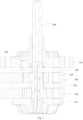
- an embodiment of the first aspect of the present invention provides a compressor 100, comprising a housing 110, wherein a first gas outlet port 112 and a second gas outlet port 114 are provided on the housing 110, a first bearing 120 is provided in the housing 110, a first cylinder 140 is provided in the housing 110, the first cylinder 140 comprises a first working chamber, and a second cylinder 150 is provided in the housing 110, wherein the second cylinder 150 comprises a second working chamber, and the second working chamber is communicated to the second gas outlet port 114 via an inner chamber of the housing 110, a first separator 160 is located between the first bearing 120 and the first cylinder 140, a first exhaust port 180 is provided on the first separator 160, the first exhaust port 180 communicates with the first working chamber, an exhaust passage 190 is located in the housing 110, the first exhaust port 180 communicates with the first gas outlet port 112 via the exhaust passage 190, and the exhaust passage 190 does not communicate with the inner chamber of the housing 110, where
- the compressor 100 provided by the embodiment of the present invention comprises a housing 110, a first bearing 120, a first cylinder 140 and a first separator 160, wherein the first separator 160 is arranged between the first bearing 120 and the first cylinder 140, specifically, the first cylinder 140 comprises a first working chamber, and the compression of the gas is achieved by a volume change of the first working chamber.
- a side of the first separator 160 facing the first cylinder 140 is provided with a first exhaust port 180 which is communicated with the first working chamber, that is, the first working chamber exhausts gas through the first exhaust port 180 when compressing and exhausting the air.
- the compressor 100 further comprises an exhaust passage 190, and the housing 110 is provided with a first gas outlet port 112, wherein one end of the exhaust passage 190 is communicated with the first exhaust port 180, and the other end of the exhaust passage 190 is communicated with the first gas outlet port 112, and the exhaust passage 190 and the inner chamber of the housing 110 are not communicated with each other, that is to say, the exhaust passage 190 through which the first working chamber flows during exhaustion is not communicated with the inner chamber of the housing 110, but directly exhausts gas out of the housing 110 of the compressor 100 through the first gas outlet port 112 of the housing 110.
- the sealing performance in the exhaust process of the first working chamber is effectively increased, that is to say, leakage of the first working chamber into the inner chamber of the housing 110 upon exhaustion is reduced, so that the pressure of the gas exhausted from the first working chamber can be increased, such that the actual displacement from the first working chamber can be closer to theoretically designed displacement, thereby improving the energy efficiency of the compressor 100.
- the compressor 100 further comprises a second cylinder 150, and in particular, the second cylinder 150 comprises a second working chamber, wherein the second cylinder 150 and the first cylinder 140 are distributed on an axial direction of the housing 110, and two cylinders compress the gas independently, so as to facilitate dual-pressure exhaustion of the compressor 100.
- both the first cylinder 140 and the second cylinder 150 can achieve intake, compression and exhaust processes of the refrigerant, and this arrangement avoids the problem of high cost caused by providing multiple compressors 100 to implement the double exhaust function in the related art, and one compressor 100 in the present invention can achieve the functions that can be implemented by two compressors 100 in the related art, reducing the machining cost, reducing the occupied space of the compressor 100, and facilitating the installation process of the compressor 100.
- the exhaust pressure of the first working chamber is greater than the exhaust pressure of the second working chamber, that is to say, it is defined that the exhaust pressure of the first cylinder 140 and the second cylinder 150 are different.
- Different exhaust pressure can make the time when the refrigerant reaches the predetermined temperature and the energy required to be different, and it can be understood that the first cylinder 140 and the second cylinder 150 achieve different exhaust pressure according to different usage requirements of the compressor 100.
- the condenser corresponding to the first cylinder 140 and the second cylinder 150 can achieve the condensation function efficiently, avoid wasting energy, make full use of the dual exhaust advantages of the double-cylinder compressor 100, and significantly improve the energy efficiency of the compressor 100.
- the compressor 100 also comprises a first piston and a second piston, the first cylinder 140 is processed and formed with the first accommodating chamber, and the first piston is eccentrically arranged in the first accommodating chamber, the second cylinder 150 is also machined with a second accommodating chamber, the second piston is eccentrically positioned within the second accommodating chamber, and the first piston can reciprocate within the first accommodating chamber, so that the first piston achieves intake, compression of air and exhaust processes by changing a volume of the first working chamber, and the second piston can reciprocate within the second accommodating chamber, so that the second piston achieves intake, compression of air and exhaust processes by changing the volume of the second working chamber, the double exhaust function is achieved by providing two cylinders and two pistons, the first cylinder 140 and the second cylinder 150 both are able to achieve intake, compression and exhaust processes of the refrigerant; this arrangement avoids the problem of high cost caused by arranging multiple compressors 100 to achieve double exhaust function in the related art; one compressor 100 in the present invention can achieve the functions which can be achieved by two compressors 100 in the related art, reducing
- the first separator 160 defined in the present invention is provided between the first bearing 120 and the first cylinder 140, but the first bearing 120 and the first cylinder 140 are not specifically defined as an upper bearing and an upper cylinder in the double-cylinder compressor 100.
- the first bearing 120 can be an upper bearing located on an axial direction of the compressor 100 housing 110
- the first cylinder 140 can be a lower bearing and a lower cylinder located on the axial direction of the compressor 100 housing 110
- the first separator 160 may be located between the upper bearing and the upper cylinder, or may be located between the lower bearing and the lower cylinder
- the first gas outlet port 112 is communicated with the first exhaust port 180 via an exhaust passage 190 to the working chamber in the upper cylinder
- the first separator 160 is located in the lower bearing and the lower cylinder
- the first gas outlet port 112 is communicated with the first exhaust port 180 via the exhaust passage 190 to the working chamber in the lower cylinder, so that the corresponding working chamber can be sealed by adding the first separator 160, reduce the leakage to the inner chamber of the housing 110 when the working chamber is exhausted air, achieving an increase in the energy efficiency of the compressor 100.
- a first separator 160 is provided between a second bearing 130 and a second cylinder 150, and a first exhaust port 180 is provided on a side of the first separator 160 facing the second cylinder 150.
- the first exhaust port 180 is communicated with the second working chamber, and a second exhaust passage 194 is provided on a side of the first separator 160 facing the second bearing 130; a side of the second bearing 130 facing the first separator is provided with a first exhaust passage 192, and one end of the first exhaust passage 192 is communicated with a second exhaust passage 194; the other end of the first exhaust passage 192 is provided inside the second bearing 130 and extends along the radial direction of the second bearing 130 until the end of the second bearing 130 is communicated with a first gas outlet port 112, so that the second working chamber exhausts gas from the first exhaust port 180 to the housing via the second exhaust passage 194, the first exhaust passage 192, and the first gas outlet port 112.
- the first working chamber then diffuses from the third exhaust port, through an outlet passage 210, to the inner cavity of the housing, and exhausts gas to the housing through the second gas outlet port 114 at the top.
- the exhaust process of the second working chamber can be sealed to prevent leakage to the inner chamber of the housing when the second working chamber exhausts air, thereby increasing the pressure of the gas exhausted from the second working chamber, allowing the actual displacement from the second working chamber can be closer to theoretically designed displacement, thereby increasing the energy efficiency of the compressor 100.
- the exhaust passage 190 comprises a first exhaust passage 192 and a second exhaust passage 194, wherein the first exhaust passage 192 is provided on the first bearing 120, the first exhaust passage 192 is communicated with the first gas outlet port 112, and the second exhaust passage 194 is provided on the first separator 160, one end of the second exhaust passage 194 is communicated with the first exhaust passage 192 and the other end of the second exhaust passage 194 is communicated with the first exhaust port 180.
- the exhaust passage 190 comprises the first exhaust passage 192 and the second exhaust passage 194, wherein since the exhaust passage 190 is not communicated with the inner chamber of the housing 110, that is, neither the first exhaust passage 192 nor the second exhaust passage 194 is communicated with the inner chamber of the housing 110, it is guaranteed that the first working chamber communicated with the exhaust passage 190 can be separately exhausted from the first gas outlet port 112.
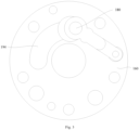
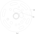
- the first exhaust passage 192 is arranged on the first bearing 120, and the second exhaust passage 194 is arranged on the first separator 160, wherein the second exhaust passage 194 is arranged on one side of the first separator 160 near the first bearing 120; the second exhaust passage 194 is communicated with the first exhaust port 180, and one end of the first exhaust passage 192 communicated with the second exhaust passage 194 is provided on one side of the first bearing 120 close to the first separator 160; and the first exhaust passage 192 extends inside the first bearing 120 along the radial direction to the end of the first bearing 120, and is communicated with the first gas outlet port 112 through the end of the first bearing 120.
- first exhaust passage 192 and second exhaust passage 194 By placing the first exhaust passage 192 and second exhaust passage 194 on the first bearing 120 and first separator 160 and combining the same into a sealed chamber, the sealing effect of the exhaust passage 190 is improved, further preventing leakage of the first working chamber to the inner chamber of the housing 110 during exhaustion, increasing energy efficiency of the compressor 100.
- the exhaust passage 190 on the first separator 160 and the first bearing 120 and communicating the same with the first cylinder 140, the length originally required by the exhaust passage 190 is shortened, the leakage to the inner chamber of the housing 110 when the first working chamber is exhausted is further reduced, the exhaust pressure of the first working chamber is improved, and it is unnecessary to additionally provide exhaust passage 190 in the location of the first cylinder 140 away from the sliding vane slot, thereby effectively reducing the damage to the first cylinder 140, ensuring the rigidity of the first cylinder 140, and thus improving the use reliability of the compressor 100.
- a second exhaust passage is provided on a side of the first separator 160 facing the first bearing 120, and the second exhaust passage is communicated with the first exhaust port 180, a first exhaust passage is provided on a side of the first bearing 120 facing the first separator 160, the first exhaust passage and the second exhaust passage together form a sealed chamber, and a third exhaust passage is also provided inside the first bearing 120; the third exhaust passage is communicated with the sealed chamber, so that the sealed cavity formed by the first exhaust passage and the second exhaust passage and the third exhaust passage together constitute an exhaust passage which is not in communication with the inner cavity of the housing, and the exhaust passage is in communication with the first working chamber, so that when the first working chamber intakes, compresses and exhausts air, the first exhaust port 180 is communicated to the first gas outlet port 112 via the exhaust passage, and is directly exhausted out of the housing 110 of the compressor 100 through the first gas outlet port 112 of the housing 110.
- the first bearing 120 is provided with a shaft hole
- the first exhaust passage 192 comprises a first side wall near one side of the shaft hole
- the minimum distance between the first side wall and the side wall of the shaft hole is L1, wherein L1 ⁇ 0.5 mm.
- the first exhaust passage 192 has a first side wall on the side of the shaft hole adjacent the first bearing 120, the minimum distance between the first side wall and the shaft hole side wall being greater than or equal to 0.5 mm, i.e., by defining the minimum distance between the first side wall and the shaft hole side wall, i.e., defining the position of the first exhaust passage 192 relative to the shaft hole, if the distance between the first side wall and the shaft hole side wall is too small, there is an increased risk that the exhaust passage 190 will go to the inner cavity of the housing 110 during exhaustion of the first working chamber.
- the location of the first exhaust passage 192 with respect to the shaft hole of the first bearing 120 is defined, so that the sealing performance of the first exhaust passage 192 can be guaranteed, the leakage of the first working chamber during exhaustion can be further prevented, and the energy efficiency of the compressor 100 can be improved.
- a shaft hole is provided on the first separator 160
- the second exhaust passage 194 comprises a second side wall near one side of the shaft hole, and the minimum distance between the second side wall and the sidewall of the shaft hole is L2, wherein L2 ⁇ 0.5 mm.
- the second exhaust passage 194 has a second side wall on the side of the shaft hole near the first separator 160, the minimum distance between the second side wall and the shaft hole sidewall of the first separator 160 is greater than or equal to 0.5 mm, that is to say, by defining the minimum distance between the second side wall and the shaft hole sidewall of the first separator 160, that is to say, the location where the second exhaust passage 194 is located relative to the shaft hole of the first separator 160 is defined, if the second between the second side wall and the side wall of the shaft hole is too small, there is an increased risk of leakage of the exhaust passage 190 into the interior of the housing 110 during exhaustion of the first working chamber.
- the location of the second exhaust passage 194 with respect to the shaft hole of the first separator 160 is defined such that the sealing performance of the second exhaust passage 194 can be secured, further preventing leakage of the first working chamber during exhaustion, and improving the energy efficiency of the compressor 100.
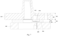
- the relationship between a thickness of the first separator 160, a depth of the second exhaust passage 194 and a height of the first exhaust port 180 is defined; as shown in figure 7 , further, the thickness of the first separator 160 is H1; the depth of the second exhaust passage 194 along an axial direction of the housing 110 is D1, and the height of the first exhaust port 180 along an axial direction of the housing 110 is h1, wherein the thickness H1 of the first separator 160, the depth D1 of the second exhaust passage 194 and the height h1 of the first exhaust port 180 satisfy H1-D1 > 5 * (D1-h1).
- the relationship between the thickness of the first separator 160, the depth of the second exhaust passage 194 along the axial direction of the housing 110, and the height of the first exhaust port 180 along the axial direction of the housing 110 is defined so as to satisfy H1-D1 > 5 * (D1-h1), that is to say, the height of the first exhaust port 180 relative to the first separator 160 and the depth of the second exhaust passage 194 provided on the first separator 160 are defined.
- the second exhaust passage 194 is too deep, the structural strength of the first separator 160 will be reduced, and the service stability of the compressor 100 will be reduced.
- the second exhaust passage 194 is too shallow, the effective flow area of the exhaust passage 190 cannot be guaranteed; at the same time, if the height of the first exhaust port 180 in the axial direction of the housing 110 is too high, the depth of a section of the second exhaust passage 194 communicating with the first exhaust port 180 is shallow, and then the flow area of the gas cannot be guaranteed; if the height of the first exhaust port 180 in the axial direction of the housing 110 is too low, the second exhaust passage 194 communicates with the first exhaust passage 192 and the first exhaust port 180 at the same time; the depth of the channel required to be provided is relatively deep, thereby reducing the structural strength of the first separator 160; therefore, the relationship between the thickness of the first separator 160, the depth of the second exhaust channel 194 in the axial direction of the housing 110 and the height of the first exhaust port 180 along the axial direction of the housing 110 is defined, that is, the machining process of the first separator 160 is defined, thereby ensuring the flatness of the sealing surface of the first separator 160, and at the same
- the relationship between a thickness of the first bearing 120, a depth of the first exhaust passage 192 and the height of the first exhaust port 180 is defined, and as shown in Fig. 7 , further, the thickness of the first bearing 120 is H2, and the depth of the first exhaust passage 192 along the axial direction of the housing 110 is D2, wherein the thickness H2 of the first bearing 120, the depth D2 of the first exhaust passage 192 and the height h1 of the first exhaust port 180 satisfy H2-D2 > 5 * (D2-h1).
- the relationship between the thickness of the first bearing 120, the depth of the first exhaust passage 192 along the axial direction of the housing 110, and the height of the first exhaust port 180 along the axial direction of the housing 110 is defined so as to satisfy H2-D2 > 5 * (D2-h1), that is to say, the depth of the second exhaust passage 194 provided on the first bearing 120 is defined, that is, the effective flow area of the sealed exhaust passage 190 communicating with the first working chamber is defined, specifically, if the first exhaust passage 192 is too deep, the structural strength of the first bearing 120 would be reduced and the service stability of the compressor 100 would be reduced; if the first exhaust passage 192 is too shallow, the effective flow area of the exhaust passage 190 would not be guaranteed; therefore, the relationship between the thickness of the first bearing 120, the depth of the first exhaust passage 192 in the axial direction of the housing 110 and the height of the first exhaust port 180 along the axial direction of the housing 110 is defined, that is, the machining process of the first bearing 120 is defined, thereby ensuring the flatness
- the maximum cross-sectional area of the first exhaust port 180 is Sl and the minimum cross-sectional area of the exhaust passage 190 is S2, wherein Sl and S2 satisfy S 1 S 2 ⁇ 0.6 .
- a range of values of the ratio of the maximum cross-sectional area of the first exhaust port 180 to the minimum cross-sectional area of the exhaust passage 190 is further defined, specifically, the ratio of the maximum cross-sectional area of the first exhaust port 180 to the minimum cross-sectional area of the exhaust passage 190 is greater than or equal to 0.6, so that the flow area of the exhaust passage 190 can be guaranteed.
- a connection line between the center point of the first exhaust port 180 and the center point of the first separator 160 extends as a first face in the axial direction of the housing 110;
- a side of the exhaust passage 190 close to the first gas outlet port 112 comprises a second exhaust port, the second exhaust port is in communicated with the first gas outlet port 112 and the first exhaust port 180 respectively, the center line of the second exhaust port is able to pass through the center of the first bearing 120, and the center line extends in the axial direction of the housing 110 as a second face; an angle ⁇ is formed between the first face and the second face, wherein the angle ⁇ satisfies 140° ⁇ 330°.
- a range of values of included angle between the centerline of the exhaust passage 190 and the first exhaust port 180 along the radial direction of the first separator 160 is defined.
- the center point of the first exhaust port 180 is connected to the axis of the first separator 160, and the side of the exhaust passage 190 near the first gas outlet port 112 has the second exhaust port, the centerline of the second exhaust port can pass through the center of the first bearing 120, and the connecting line and the centerline of the second exhaust port respectively extend along the axial direction of the housing 110 as a first face and a second face, wherein the first face and the second face form an angle ⁇ on the extended direction, and the angle ⁇ satisfies 140° ⁇ 330°, which can reduce the tooling interference during the assembly process between the components and parts of the compressor 100, facilitate the manufacture of the compressor 100 and improve the assembly efficiency.
- the compressor 100 further comprises: a second bearing 130 spaced apart from the first bearing 120, and the first cylinder 140 and the second cylinder 150 are located between the first bearing 120 and the second bearing 130.
- the compressor 100 further comprises a second bearing 130, wherein the second bearing 130 and the first bearing 120 are spaced apart on an axial direction of the housing 110, and the first cylinder 140 and the second cylinder 150 are provided between the first bearing 120 and the second bearing 130, and specifically, the first bearing 120 can provide support for the crankshaft 200, and the second bearing 130 can provide support for the first cylinder 140 and the second cylinder 150, and improve the installation stability of the first cylinder 140 and the second cylinder 150.
- the compressor 100 further includes: a second separator 170 located between the first cylinder 140 and the second cylinder 150; the first bearing 120 and the second separator 170 abut against the first cylinder 140, and the second bearing 130 and the second separator 170 abut against the second cylinder 150.
- the compressor 100 further comprises a second separator 170, and in particular, the second separator 170 is arranged between the first cylinder 140 and the second cylinder 150, the first cylinder 140 and the second cylinder 150 are further arranged between the first bearing 120 and the second bearing 130, so that the first bearing 120 and the second separator 170 block the first accommodating chamber of the first cylinder 140 therebetween, and the second bearing 130 and the second separator 170 block the second accommodating chamber of the second cylinder 150 therebetween.
- the second separator 170 is arranged between the first cylinder 140 and the second cylinder 150
- the first cylinder 140 and the second cylinder 150 are further arranged between the first bearing 120 and the second bearing 130, so that the first bearing 120 and the second separator 170 block the first accommodating chamber of the first cylinder 140 therebetween, and the second bearing 130 and the second separator 170 block the second accommodating chamber of the second cylinder 150 therebetween.
- the second separator 170 comprises a first plate and a second plate, and the first plate and the second plate form a chamber, so that a third exhaust port can be provided on the second plate, so that the compressed air in the second working chamber can be exhausted into the chamber of the second separator 170 via a third exhaust port, and then the compressed air is exhausted into the second gas outlet port 114 via the gas outlet passage 210;
- the first separator 160 is provided with a first exhaust port 180, and the compressed air in the first working chamber can be exhausted to the first gas outlet port 112 via the first exhaust port 180, guaranteeing that first cylinder 140 and second cylinder 150 can achieve exhaust function independently of each other, and achieving double pressure exhaust function of the compressor 100.
- the second separator 170 includes a first plate, a second plate, and a separator, the separator separating the chamber within the first plate and the second plate, thereby separating the chamber into two mutually independent ones.
- a first exhaust port 180 may be provided on the first plate, so that the compressed air in the first working chamber can be exhausted to one of the chambers through the first exhaust port 180, and then the compressed air is exhausted to the first gas outlet port 112 through the exhaust passage 190;
- a third exhaust port may also be provided on the second plate, and the compressed air in the second working chamber can be exhausted to the other chambers through the third exhaust port, and then the compressed air is exhausted to the second gas outlet port 114 through the inner chamber of the housing 110. It is guaranteed that the exhaust processes of the first cylinder 140 and the second cylinder 150 do not affect each other, achieving the double pressure exhaust function of the compressor 100.
- the compressor 100 further comprises a first sliding vane assembly and a second sliding vane assembly, wherein the first cylinder 140 comprises a first sliding vane slot, the second cylinder 150 comprises a second sliding vane slot, the first sliding vane assembly is arranged in the first sliding vane slot, the second sliding vane assembly is arranged in the second sliding vane slot, the first sliding vane assembly, the outer peripheral surface of the first piston and the inner surface of the first cylinder 140 form a first working chamber, the second sliding vane assembly, the outer peripheral surface of the second piston and the inner surface of the second cylinder 150 form a second working chamber, and the first piston movement can change the volume of the first working chamber to compress air, and the second piston movement can change the volume of the second working chamber to compress the air.
- the first sliding vane assembly comprises a first sliding vane and a first elastic member, wherein the first sliding vane compresses the outer peripheral surface of the first piston, and the first elastic member is connected to an end of the first sliding vane away from the first piston, so that during the movement of the first piston, the first elastic member can push the first sliding vane to always keep compressing the outer peripheral surface of the first piston, ensuring the sealing performance of the first working chamber.
- the first sliding vane assembly includes the first sliding vane, and the first sliding vane can be integrated with the first piston to prevent the first sliding vane from falling out of the first sliding vane slot, ensure the stable installation of the first sliding vane, improve the reliability of product, and the integrated structure has good mechanical properties, thus improving the connection strength between the first sliding vane and the first piston.
- the first sliding vane is integrally formed with the first piston, facilitating mass production, improving the processing efficiency of the product and reducing the processing cost of the product.
- the first sliding vane can also be hingedly connected with the first piston, and can also serve to prevent the first sliding vane from falling out of the first sliding vane slot, so as to stabilize the installation of the first sliding vane and improve the reliability of the product.
- the second sliding vane assembly includes the second sliding vane and the second elastic member.
- the second sliding vane compresses the outer peripheral surface of the second piston, and the second elastic member is connected to the end of the second sliding vane away from the second piston, so that during the movement of the second piston, the second elastic member can push the second sliding vane to always compress the outer peripheral surface of the second piston, ensuring the sealing performance of the second working chamber.
- the second sliding vane assembly includes a second sliding vane which can be integrated with the second piston to prevent the second sliding vane from falling out of the second sliding vane slot, ensure the stable installation of the second sliding vane, improve the reliability of product, and the integrated structure has good mechanical properties, thus improving the connection strength between the second sliding vane and the second piston.
- the second sliding vane is integrally formed with the second piston, which facilitates mass production, improves the processing efficiency of the product and reduces the processing cost of the product.
- the second sliding vane can also be hingedly connected with the second piston, and can also serve to prevent the second sliding vane from falling out of the second sliding vane slot, so as to stabilize the installation of the second sliding vane and improve the reliability of the product.
- the compressor 100 further comprises: a crankshaft 200 and a motor assembly, wherein the motor assembly includes a stator and a rotor, the crankshaft 200 has a first eccentric portion and a second eccentric portion, the first piston is connected to the first eccentric portion, the second piston is connected to the second eccentric portion; a motor assembly connected to the crankshaft 200 to drive the crankshaft 200 to rotate.
- the motor assembly includes a stator and a rotor
- the crankshaft 200 has a first eccentric portion and a second eccentric portion, the first piston is connected to the first eccentric portion, the second piston is connected to the second eccentric portion; a motor assembly connected to the crankshaft 200 to drive the crankshaft 200 to rotate.
- the compressor 100 further comprises a crankshaft 200 and a motor assembly, wherein the motor assembly can drive the crankshaft 200 to rotate, the crankshaft 200 has a first eccentric portion connected to the first piston and a second eccentric portion connected to the second piston, when the crankshaft 200 rotates, the first eccentric portion on the crankshaft 200 drives the first piston to rotate, and the rotating first piston achieves functions of intake, compression and exhaustion of the air.
- the second eccentric portion on the crankshaft 200 rotates the second piston, and the rotating second piston achieves intake, compression and exhaustion functions on the air.
- the low pressure gas passes from the first intake passage into the first working chamber of the first cylinder 140, completing the process of intake, compression and exhaust in the first working chamber, and exhausting via the first gas outlet passage 210.
- the other low-pressure gas second intake passage enters the second working chamber of the second cylinder 150 to complete the process of intake, compression and exhaustion in the second working chamber, and gas is exhausted through the second gas outlet passage 210, and the crankshaft 200 completes the exhaust process twice per revolution.
- the compressor 100 further comprises: a second gas outlet port 114 provided on the housing 110; a third exhaust port communicated with the second working chamber, a third exhaust port communicated with the second gas outlet port 114 via the inner chamber of the housing 110; a gas outlet passage 210 through which a third exhaust port is communicated with an inner chamber of the housing 110; the gas outlet passage 210 is not communicated with the exhaust passage 190.
- the compressor 100 further comprises a second gas outlet port 114, and specifically, the second gas outlet port 114 is provided at the top of the housing 110, and the third exhaust port is communicated with the second working chamber, wherein the second working chamber communicates from the third exhaust port to the inner chamber of the housing 110 via the gas outlet passage 210, and gas is exhausted out of the housing 110 from the second gas outlet port 114. That is, the gas in the second working chamber is exhausted through the third exhaust outlet, diffused into the inner chamber of the housing 110, and then exhausted through the second gas outlet port 114. Since the exhaust pressure of the second cylinder 150 is smaller than the exhaust pressure of the first cylinder 140, the gas pressure in the inner chamber of the housing 110 is relatively low, facilitating the oil return of the compressor 100, and facilitating the reliability for ensuring the operation of the compressor 100.
- the compressor 100 further comprises a first seal and a second seal, and in particular, the first seal partially covers the first bearing 120 and the second seal partially covers the second bearing 130, and by providing the first seal and the second seal, the first bearing 120 and the second bearing 130 can be partially covered by the first seal and the second seal, respectively, which can effectively reduce the noise generated during the operation of the compressor 100 and improve the use experience of the user.
- an exhaust chamber is formed between the second seal and the second bearing 130, the exhaust chamber communicated with the gas outlet passage 210 and the third exhaust port, that is, the exhaust chamber communicated with the second working chamber.
- first seal and the second seal are cover plates or silencers.
- the first seal and the second seal are connected at other positions by bolts or welding.
- the compressor 100 further comprises a first exhaust valve 220 and a second exhaust valve, and in particular, the first exhaust valve is arranged on the first exhaust port 180 and the second exhaust valve is arranged on the gas outlet passage 210.
- the first exhaust valve 220 can open and close the first exhaust port 180
- the second exhaust valve 220 can open and close the outlet passage 210.
- the compressor 100 further comprises: the housing 110 is provided with an intake port, and the compressor 100 further comprises a first intake passage 380 and a second intake passage 390, wherein the first working chamber is communicated with the intake port via the first intake passage 380, and the second working chamber is communicated with the intake port via the second intake passage 390. Furthermore, the first intake passage 380 is communicated with the second intake passage 390.
- an intake port may be provided on the housing 110 such that both the first working chamber and the second working chamber communicate with an intake port.
- the first working chamber communicates with the intake port via the first intake passage 380
- the second working chamber communicates with the intake port via the second intake passage 390
- the first intake passage 380 and the second intake passage 390 optionally communicate with each other, so as to reduce the total length of the intake passage, avoid affecting the rigidity due to excessive machining of components such as a cylinder and a bearing, and reduce the production cost.
- the compressor 100 further comprises: the housing 110 is provided with two intake ports, and the compressor 100 further comprises a first intake passage 380 and a second intake passage 390, wherein the first working chamber is communicated with one intake port via the first intake passage 380, and the second working chamber is communicated with the other intake port via the second intake passage 390, and the first intake passage 380 and the second intake passage 390 are not communicated with each other.
- first intake passage 380 is provided on the first cylinder 140 or the first bearing 120 or the second separator 170
- second intake passage 390 is provided on the second cylinder 150 or the second bearing 130 or the second separator 170.
- the first intake passage 380 is arranged on the first cylinder 140, and the gas enters the first working chamber through the first intake passage 380, so as to achieve the process of intaking the gas into the first working chamber;
- a second intake passage 390 is provided on the second cylinder 150 and is communicated with the second working chamber, and the gas enters the second working chamber through the second intake passage 390, so as to implement a process of intaking the gas into the second working chamber.
- the first intake passage 380 is arranged on the first cylinder 140 and is communicated with the first working chamber, and the gas enters the first working chamber via the first intake passage 380 to achieve the process of intaking the gas into the first working chamber;
- a second intake passage 390 is provided on the second bearing 130 and is communicated with the second working chamber, and the gas enters the second working chamber through the second intake passage 390, thereby enabling the intake of the gas into the second working chamber.
- the first intake passage 380 is arranged on the first bearing 120 and is communicated with the first working chamber, and the gas enters the first working chamber through the first intake passage 380, thereby achieving a process of intaking the gas into the first working chamber;
- the second intake passage 390 is placed on the second cylinder 150, and the gas enters the second working chamber through the second intake passage 390, thereby implementing the process of intaking the gas into the second working chamber.
- the first intake passage 380 is provided on the first bearing 120, and the gas enters the first working chamber through the first intake passage 380, thereby achieving the process of intaking the gas into the first working chamber;
- a second intake passage 390 is provided on the second bearing 130, and the gas enters the second working chamber through the second intake passage 390, thereby achieving the process of intaking the gas into the second working chamber.
- a refrigeration device comprising the compressor 100 as provided by any one of the above-mentioned embodiments, and therefore all the advantageous technical effects of the compressor 100 are provided, which will not be described in detail herein.
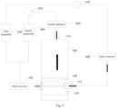
- the refrigeration device further comprises: a first condenser 300 communicated with the first gas outlet port 112 of the compressor 100; a first throttle element 310 communicated with the first condenser 300; a first evaporator 320 communicated with the first throttle element 310; a first reservoir 330, a first intake passage 380 communicating the first evaporator 320 with the compressor 100; a second condenser 340 communicated with the second gas outlet port 114 of the compressor 100; a second throttle element 350 communicated with the second condenser 340; a second evaporator 360 communicated with the second throttle element 350; a second reservoir 370, a second intake passage 390 communicating the second evaporator 360 with the compressor 100.
- the compressor 100 and the first condenser 300, the first throttle element 310, the first evaporator 320 and the first reservoir 330 form a first group of refrigeration systems
- the compressor 100 and the second condenser 340, the second throttle element 350, the second evaporator 360 and the second reservoir 370 form a second group of refrigeration systems, wherein the two groups of refrigeration systems are independent from each other, that is, the refrigeration device realizes the multiple exhaust functions realized by multiple compressors 100 in the related art by one compressor 100, thereby reducing the processing cost of the refrigeration device.
- the space occupied by the refrigeration device is also reduced, and the convenience of installing the internal components of the refrigeration device is improved; since the exhaust pressure of the first cylinder 140 and the second cylinder 150 is different, the exhaust pressure reaching the first condenser 300 and the second condenser 340 is different, so that the refrigeration device can have a double condensation temperature and a double evaporation temperature, which is beneficial to realize the cascade utilization of energy and improve the energy efficiency of the refrigeration device. Especially in case where the displacement of first cylinder 140 and second cylinder 150 is different, so that the amount of refrigerant condensed by the first condenser 300 and the second condenser 340 are also different, further improving the energy efficiency of the refrigeration device.
- the flow process of the refrigerant is as follows.
- the first gas outlet port 112 of the compressor 100 is connected to the first condenser 300 via components such as pipelines, and the refrigerant flows into the first evaporator 320 via the first expansion valve, and flows from the first evaporator 320 into the first intake passage 380 of the first cylinder 140 via the first intake passage of the first reservoir 330; the first gas outlet port 112 is connected to the second condenser 340 through a pipe assembly, and the refrigerant flows into the second evaporator 360 through the second expansion valve, and flows from the second evaporator 360 into the second intake passage 390 of the second cylinder 150 through the second reservoir 370.
- the refrigeration device further comprises: a third condenser 400 communicated with the first gas outlet port 112 of the compressor 100; a third throttle element 410 communicated with the third condenser 400; a third evaporator 420 communicated with third throttle element 410; a third reservoir 430, a first intake passage 380 and a second intake passage 390 communicating the third evaporator 420 with the compressor 100; a fourth condenser 440 communicated with the second gas outlet port 114 of the compressor 100; a fourth throttle element 450 communicated with the fourth condenser 440; a fourth evaporator 460 communicated with the fourth throttle element 450; a third reservoir 430 also communicates the fourth evaporator 460 with the first intake passage 380 and the second intake passage 390 of the compressor 100.
- the compressor 100 and the third condenser 400, the third throttle element 410, the third evaporator 420, and the third reservoir 430 form a third group of refrigeration systems
- the compressor 100 and the fourth condenser 440, the fourth throttle element 450, the fourth evaporator 460, and the third reservoir 430 form a fourth group of refrigeration systems, wherein two groups of refrigeration systems are independent from each other, that is, a refrigeration device realizes multiple exhaust functions realized by a plurality of compressors 100 in the related art by one compressor 100, thereby reducing the processing cost of the refrigeration device.
- the space occupied by the refrigeration device is also reduced, and the convenience of installing the internal components of the refrigeration device is improved; the first intake passage 380 and the second intake passage 390 communicate with the third reservoir 430, so that providing one reservoir can satisfy the intake function of the first cylinder 140 and the second cylinder 150, reducing the number of components in the refrigeration device, further reducing the processing cost of the refrigeration device, effectively reducing the volume of the refrigeration device, and improving the convenience of installing the refrigeration device.
- the refrigeration device can be provided with the double condensing temperature and the double evaporating temperature, facilitating the cascade utilization of energy, and improving the energy efficiency of the refrigeration device.
- the displacement of the first cylinder 140 and the second cylinder 150 are different, so that the amount of the refrigerant condensed by the third condenser 400 and the fourth condenser 440 is also different, further improving the energy efficiency of the refrigeration device.
- the above-mentioned two embodiments achieve the function of double exhaust parameters of a single compressor 100, and make use of heat with double high and low temperatures to effectively save energy consumption. Meanwhile, the range of the parameter ratio of the double cylinders is reasonably specified, the advantages of double-row circulation can be fully exerted, and the energy efficiency is improved.
- connect may be a fixed connection, a detachable connection, or an integral connection; may be directly connected or indirectly connected through an intermediate.
- connect may be a fixed connection, a detachable connection, or an integral connection; may be directly connected or indirectly connected through an intermediate.
Landscapes
- Engineering & Computer Science (AREA)
- Mechanical Engineering (AREA)
- General Engineering & Computer Science (AREA)
- Physics & Mathematics (AREA)
- Thermal Sciences (AREA)
- Applications Or Details Of Rotary Compressors (AREA)
Description
- The embodiment of the present invention relates to the field of compressors, in particular to a compressor and a refrigeration device.
- At present, a rolling rotor double-cylinder compressor in the related art refers to a compression assembly containing two cylinders arranged on a crankshaft axial direction, and both cylinders can achieve intake, compression and exhaust processes of the refrigerant, the two cylinders of the double-cylinder compressor exhaust gas out of the housing through different exhaust passages, thereby realizing double exhaust pressure which can effectively save space and energy consumption which was originally achieved by the two compressors. However, in the related art, it is difficult to completely seal the upper and lower cylinders of the double-cylinder compressor during gas exhaustion, resulting in an actual displacement of each exhaust circuit lower than theoretical design displacement, thus affecting energy efficiency.
CN110863987A relates generally to a dual-cylinder compressor comprising a housing, wherein the housing is provided with a first gas outlet port and a second gas outlet port; a first cylinder provided in the housing and comprising a first working chamber; a second cylinder provided in the housing and comprising a second working chamber, the second working chamber being communicated with the second gas outlet port via an inner chamber of the housing; the first working chamber being communicated with the first gas outlet port via an exhaust passage located within the housing being not communicated with the inner chamber of the housing. -
CN109595251A relates generally to a compressor with a bearing unit, wherein the bearing unit comprises a bearing and an exhaust separation plate.CN103821716B relates generally to a two-stage rotary compressor and a refrigeration circulating device provided with the two-stage rotary compressor. - Aspects of the invention are set out in the claims. In the following, each of the described methods, apparatuses, embodiments, examples, and aspects, which do not fully correspond to the invention as defined in the claims is thus not according to the invention and is, as well as the whole following description, present for illustration purposes only or to highlight specific aspects or features of the claims. Embodiments not falling under the scope of the claims should be interpreted as examples useful for understanding the invention. The embodiments of the present invention aim to solve at least one of the technical problems existing in the prior art.
- To this end, a first aspect of the embodiment of the present invention provides a compressor.
- A second aspect of the embodiment of the present invention provides a refrigeration device.
- In view of this, according to a first aspect of the embodiment of the present invention, a compressor is provided, wherein the compressor comprises: a housing, wherein the housing is provided with a first gas outlet port and a second gas outlet port, a first bearing is provided in the housing, and a first cylinder is provided in the housing. The first cylinder comprises a first working chamber, and a second cylinder is provided in the housing, wherein the second cylinder comprises a second working chamber connected to the second gas outlet port via an inner chamber of the housing, a first separator is located between the first bearing and the first cylinder, and a first exhaust port is provided on a first separator, the first exhaust port is communicated with the first working chamber, an exhaust passage is located in the housing, the first exhaust port is communicated with the first gas outlet port via the exhaust passage, and the exhaust passage and the inner chamber of the housing are not communicated with each other; wherein an exhaust pressure of the first working chamber is greater than the exhaust pressure of the second working chamber.
- The compressor provided by an embodiment of the present invention comprises a housing, a first bearing, a first cylinder and a first separator, wherein the first separator is arranged between the first bearing and the first cylinder, specifically, the first cylinder comprises a first working chamber, and compression of the gas is achieved by a volume change of the first working chamber. Specifically, a side of the first separator facing the first cylinder is provided with a first exhaust port, and the first exhaust port is communicated with the first working chamber, that is, the first working chamber exhausts through the first exhaust port when compressing and exhausting the air. Furthermore, the compressor further comprises an exhaust passage, and the housing is provided with a first gas outlet port, wherein one end of the exhaust passage is communicated with the first exhaust port, and the other end of the exhaust passage is communicated with the first gas outlet port, and the exhaust passage and the inner chamber of the housing are not communicated with each other, that is to say, the exhaust passage through which the first working chamber flows during exhaust is not communicated with the inner chamber of the housing, but directly exhausts gas out of the compressor housing via the first gas outlet port of the housing. By adding a first separator between the first bearing and the first cylinder, and making the first working chamber communicate with the first exhaust port provided on the first separator to exhaust air, sealing performance in the exhaust process of the first working chamber is effectively improved, that is to say, leakage of the inner chamber of the first working chamber to the housing during exhaustion is reduced, so that the pressure of the gas exhausted from the first working chamber can be increased, so that the actual displacement from the first working chamber can be closer to theoretically designed displacement, thereby increasing the energy efficiency of the compressor.
- Furthermore, the compressor comprises a second cylinder, and in particular, the second cylinder comprises a second working chamber connected to a second gas outlet port via an inner chamber of the housing, wherein the second cylinder and the first cylinder are distributed on an axial direction of the housing, and the two cylinders independently compress the air, facilitating dual-pressure exhaustion of the compressor. In particular, both the first cylinder and the second cylinder can achieve intake, compression and exhaust processes of a refrigerant, and this arrangement avoids the problem of high cost caused by arranging multiple compressors to achieve the double exhaustion function in the related art, and one compressor in the present invention can achieve the functions achieved by two compressors in the related art, reducing the processing cost and occupied space of the compressor, and facilitating the installation process of the compressor. Furthermore, in the present invention, it is defined that the exhaust pressure of the first working chamber is greater than the exhaust pressure of the second working chamber, i.e., it is defined that the exhaust pressures of the first cylinder and the second cylinder are different. Different exhaust pressure can make the time when the refrigerant reaches the predetermined temperature and the energy required to be different, and it can be understood that first cylinder and second cylinder achieve different exhaust pressure according to different usage requirements of the compressor. Thus, a condenser corresponding to the first cylinder and the second cylinder can achieve the condensing function efficiently, avoid the waste of energy, make full use of the advantages of a double-cylinder compressor, and significantly improve the energy efficiency of the compressor.
- Note that for the double-cylinder compressor, the first separator defined in the present invention is provided between the first bearing and the first cylinder, but the first bearing and the first cylinder are not specifically defined as the upper bearing and the upper cylinder in the double-cylinder compressor. It can be understood that the first bearing can be an upper bearing located on an axial direction of the compressor housing, and the first cylinder can be a lower bearing and a lower cylinder located on the compressor axial direction of the housing, that is, the first separator may be located between the upper bearing and the upper cylinder, or may be located between the lower bearing and the lower cylinder, and when the first separator is located between the upper bearing and the upper cylinder, a first gas outlet port is connected to the working chamber in the upper cylinder via an exhaust passage and a first exhaust port, similarly, if the first separator is located in the lower bearing and the lower cylinder, the first gas outlet port is communicated with the working chamber in the lower cylinder via the exhaust passage and the first exhaust port, so that the corresponding working chamber can be sealed by adding the first separator, reduces leakage to the inner chamber of the housing when the working chamber is vented, resulting in an increase in compressor energy efficiency.
- Note that the compressor further comprises a first piston and a second piston, the first cylinder is formed with a first accommodating chamber, and the first piston is eccentrically arranged in the first accommodating chamber, the second cylinder is also machined with a second accommodating chamber, the second piston is eccentrically placed in the second accommodating chamber, and the first piston can reciprocate within first accommodating chamber, so that the first piston achieves intake, compression of air and exhaust processes by changing the volume of the first working chamber, and the second piston can reciprocate within the second accommodating chamber, so that the second piston achieves intake, compression of air and exhaust process by changing the volume of the second working chamber; double exhaust function is achieved by providing two cylinders and two pistons, the first cylinder and the second cylinder can achieve intake, compression and exhaust process of the refrigerant; this arrangement avoids the problem of high cost caused by arranging a plurality of compressors to achieve double exhaust function in the related art, and one compressor in the present invention can achieve the functions which can be achieved by two compressors in the related art, reducing the processing cost and reducing the occupied space of the compressor, and is beneficial to improving the convenience of installing the compressor.
- In addition, according to the compressor provided by the above-mentioned embodiment of the present invention further has the following additional technical features.
- In one possible design, the exhaust passage comprises a first exhaust passage and a second exhaust passage, wherein the first exhaust passage is provided on a first bearing, the first exhaust passage is communicated with a first gas outlet port, the second exhaust passage is provided on a first separator, one end of the second exhaust passage is communicated with the first exhaust passage, and the other end of the second exhaust passage is communicated with the first exhaust port.
- In this design, the exhaust passage includes the first exhaust passage and the second exhaust passage, wherein since the exhaust passage is not communicated with the inner chamber of the housing, that is, neither the first exhaust passage nor the second exhaust passage is communicated with the inner chamber of the housing, it is guaranteed that the first working chamber communicated with the exhaust passage can exhaust separately from the first gas outlet port. Specifically, the first exhaust passage is provided on the first bearing, and the second exhaust passage is provided on the first separator, wherein the second exhaust passage is provided on one side of the first separator close to the first bearing, and the second exhaust passage is communicated with the first exhaust port, one end of the first exhaust passage communicated with the second exhaust passage is provided on one side of the first bearing close to the first separator, and the first exhaust passage extends inside the first bearing along a radial direction to an end of the first bearing, and is communicated with the first gas outlet port through the end of the first bearing. By placing the first exhaust passage and second exhaust passage on the first bearing and first separator and combining the same to form a sealed chamber, the sealing effect of the exhaust passage is improved, leakage of the first working chamber to the inner chamber of the housing during exhaustion is further prevented, and the compressor energy efficiency is improved.
- In addition, by arranging an exhaust passage on the first separator and the first bearing and communicating the same with the first cylinder, the length originally required by the exhaust passage is shortened, the leakage into the housing chamber when the first working chamber exhausts air, the exhaust pressure of the first working chamber is improved, and there is no need to additionally provide the exhaust passage in the location of the first cylinder away from the sliding vane slot, thereby effectively reducing the damage to the first cylinder, ensuring the rigidity of the first cylinder, thereby improving the use reliability of the compressor.
- In one possible design, a shaft hole is provided on a first bearing, a first exhaust passage comprises a first side wall near one side of the shaft hole, and the minimum distance between a first side wall and a sidewall of the shaft hole is L1, wherein L1 ≥ 0.5mm.
- In this design, the first exhaust passage has a first side wall on the side of the shaft hole near the first bearing, and the minimum distance between the first side wall and the shaft hole sidewall is greater than or equal to 0.5 mm, that is, by defining the minimum distance between the first side wall and the shaft hole sidewall, i.e., defining a providing location of the first exhaust passage relative to the shaft hole, if the distance of the first side wall and the shaft hole sidewall is too small, the risk of leakage of the exhaust passage to the housing chamber is increased during exhaustion of the first working chamber. Therefore, the location of the first exhaust passage with respect to the shaft hole of the first bearing is defined so that the sealing performance of the first exhaust passage can be guaranteed, the leakage of the first working chamber during the exhaustion is further prevented, and the energy efficiency of the compressor is improved.
- In one possible design, a shaft hole is provided on the first separator, the second exhaust passage comprises a second side wall near one side of the shaft hole, and the minimum distance between the second side wall and the sidewall of the shaft hole is L2, wherein L2 ≥ 0.5 mm.
- In this design, the second exhaust passage has a second side wall on the side of the shaft hole near the first separator, and the minimum distance between the second side wall and the shaft hole sidewall of the first separator is greater than or equal to 0.5 mm, that is, by defining the minimum distance between the second side wall and the shaft hole sidewall of the first separator, i.e., defining the providing location of the second exhaust passage relative to the shaft hole of the first separator, if the distance between second side wall and shaft hole sidewall is too small, the risk of leakage of the exhaust passage to the housing chamber is increased during exhaustion of the first working chamber. Therefore, the location of the second exhaust passage with respect to the shaft hole of the first separator is defined so that the sealing performance of the second exhaust passage can be guaranteed, the leakage of the first working chamber during exhaustion is further prevented, and the energy efficiency of the compressor is improved.
- In one possible design, a thickness of the first separator is Hl, a depth of the second exhaust passage along an axial direction of the housing is D1, and a height of the first exhaust port along the axial direction of the housing is h1, wherein the thickness Hl of the first separator, the depth Dl of the second exhaust passage, and the height h1 of the first exhaust port satisfy H1-D1 > 5 * (D1-h1).
- In this design, the relationship between the thickness of the first separator, the depth of the second exhaust passage along the axial direction of the housing and the height of the first exhaust port along the axial direction of the housing is defined so as to satisfy H1-D1 > 5 * (D1-h1), that is to say, the height of the first exhaust port with respect to the first separator and the depth provided for the second exhaust passage on the first separator are defined, and specifically, if the second exhaust passage is too deep, the structural strength of the first separator is reduced and the service stability of the compressor is reduced, and if the second exhaust passage is too shallow, the effective flow area of the exhaust passage cannot be guaranteed. Meanwhile, if the first exhaust port along the axial direction of the housing is too high, the depth of a section where the second exhaust passage is connected to the first exhaust port is small, and the flow area of the gas cannot be guaranteed; if the first exhaust port is too low on an axial direction of the housing, the second exhaust passage is in communication with the first exhaust passage and the first exhaust port at the same time, and the passage required to be provided is relatively deep, thereby reducing the structural strength of the first separator. The relationship between the depth along the axial direction of the housing of the second exhaust passage and the height along the axial direction of the housing of the first exhaust port is defined, that is to say, the machining process of the first separator is defined so as to ensure the planarity of the first separator sealing surface, further preventing leakage of the first working chamber to the inner chamber of the housing while improving the service stability of the compressor, and improving the energy efficiency of the compressor.
- In one possible design, a thickness of the first bearing is H2, a depth of the first exhaust passage along the axial direction of the housing is D2, and a height of the first exhaust port on an axial direction of the housing is h1, wherein the thickness H2 of the first bearing, the depth D2 of the first exhaust passage, and the height h1 of the first exhaust port satisfy H2-D2 > 5 * (D2-h1).
- In this design, the relationship between the thickness of the first bearing, the depth of the first exhaust passage along the axial direction of the housing and the height of the first exhaust port along the axial direction of the housing is defined so as to satisfy H2-D2 > 5 * (D2-h1), that is to say, the depth provided for the second exhaust passage on the first bearing is defined, that is to say, the effective flow area of the sealed exhaust passage communicating with the first working chamber is defined; specifically, if the first exhaust passage is too deep, the structural strength of the first bearing will be reduced and the service stability of the compressor will be reduced, and if the first exhaust passage is too shallow, therefore, the effective flow area of the exhaust passage cannot be guaranteed, and therefore, the relationship between the thickness of the first bearing, the depth of the first exhaust passage along the axial direction of the housing and the height of the first exhaust port along the axial direction of the housing is defined, that is, the machining process of the first bearing is defined, so that the flatness of the sealing surface of the first bearing is guaranteed, and at the same time of improving the service stability of the compressor, leakage of the first working chamber into the inner chamber of the housing is further prevented, thereby improving the energy efficiency of the compressor.
- In one possible design, the maximum cross-sectional area of the first exhaust port is Sl and the minimum cross-sectional area of the exhaust passage is S2, wherein Sl and S2 satisfy

- In this design, the value range of the ratio of the maximum cross-sectional area of the first exhaust port to the minimum cross-sectional area of the exhaust passage is further defined, specifically, the ratio of the maximum cross-sectional area of the first exhaust port to the minimum cross-sectional area of the exhaust passage is greater than or equal to 0.6, so that the flow area of the exhaust passage can be guaranteed.
- In one possible design, a line is connected between a center point of the first exhaust port and a center point of the first separator, the line extending as a first face in the axial direction of the housing; a side of the exhaust passage close to the first gas outlet port comprises a second exhaust port, the second exhaust port is in communication with the first gas outlet port and the first exhaust port respectively, a center line of the second exhaust port is able to pass through the center of the first bearing, and the center line extends in the axial direction of the housing as a second face; an angle θ is formed between the first face and the second face, wherein the angle θ satisfies 140°<θ<330°
- In this design, a range of values of the included angle between the center line of the exhaust passage and the first exhaust port in the radial direction of the first separator is defined. Specifically, the central point of the first exhaust port is connected to the axial center of the first separator, a side of the exhaust passage close to the first gas outlet port has a second exhaust port, and the center line of the second exhaust port can pass through the center of the first bearing, and the connection line and the center line of the second exhaust port respectively extend along the axial direction of the housing to form a first face and a second face, wherein the first face and the second face form an angle θ in the extending direction, and the angle θ satisfies 140 ° ≤ θ ≤ 330 °, so that tooling interference in the assembly process between compressor parts can be reduced, facilitating the manufacture of the compressor, and improving the assembly efficiency.
- In one possible design, the compressor further comprises: a second bearing spaced from the first bearing, wherein the first cylinder and the second cylinder are located between the first bearing and the second bearing.
- In this design, the compressor further comprises a second bearing, wherein the second bearing and the first bearing are spaced apart on an axial direction of the housing, and the first cylinder and the second cylinder are arranged between the first bearing and the second bearing, and specifically, the first bearing can provide support for a crankshaft, and the second bearing can provide support for the first cylinder, the second cylinder, and improve installation stability of the first cylinder and the second cylinder.
- In one possible design, the compressor further comprises: a second separator located between the first cylinder and the second cylinder; the first bearing and the second separator abut against the first cylinder and the second bearing and the second separator abut against the second cylinder.
- In this design, the compressor further comprises a second separator, and in particular, the second separator is provided between the first cylinder and the second cylinder, and the first cylinder and the second cylinder are further provided between the first bearing and the second bearing, so that the first bearing and the second separator block the first accommodating chamber of the first cylinder therebetween, and the second bearing and the second separator block the second accommodating chamber of the second cylinder therebetween.
- Note that the compressor further comprises a first sliding vane assembly and a second sliding vane assembly, wherein the first cylinder comprises a first sliding vane slot and the second cylinder comprises a second sliding vane slot, the first sliding vane assembly is provided in the first sliding vane slot, the second sliding vane assembly is provided in the second sliding vane slot, the first sliding vane assembly, an outer peripheral surface of the first piston and an inner surface of the first cylinder form a first working chamber, the second sliding vane assembly, an outer peripheral surface of the piston and an inner surface of the second cylinder form a second working chamber; the first piston movement can change the volume of the first working chamber to compress the air, and the second piston movement can change the volume of the second working chamber to compress the air.
- In one possible design, the compressor further comprises: a second gas outlet port provided on the housing; a third exhaust port communicated with the second working chamber, a third exhaust port communicated with the second gas outlet port via the inner chamber from the housing; an gas outlet passage, via which a third exhaust port is connected to the inner chamber of the housing; the gas outlet passage is not communicated with the exhaust passage.
- In this design, the compressor also includes a second gas outlet port, specifically, the second gas outlet port is provided at the top of the housing, the third exhaust port is communicated with the second working chamber, wherein the second working chamber is communicated from the third exhaust port to the inner chamber of the housing via the gas outlet passage and exhausts gas out of the housing from the second gas outlet port. That is, the gas in the second working chamber is exhausted through the third exhaust outlet, diffused into the inner chamber of the housing, and then exhausted through the second gas outlet port. Since the exhaust pressure of the second cylinder is smaller than the exhaust pressure of the first cylinder, the gas pressure in the inner chamber of the housing is relatively low, which facilitates the oil return of the compressor and is beneficial to ensure the reliability of the compressor operation.
- In one possible design, the compressor further comprises: the housing is provided with an intake port, and the compressor further comprises a first intake passage and a second intake passage, wherein the first working chamber is communicated with the intake port via the first intake passage, and the second working chamber is communicated with the intake port via the second intake passage. Furthermore, the first intake passage is communicated with the second intake passage.
- In this design, an intake port may be placed on the housing such that both the first working chamber and the second working chamber communicate with an intake port. Specifically, the first working chamber is communicated to the intake port via the first intake passage, the second working chamber is communicated to the intake port via the second intake passage, and the first intake passage and the second intake passage are optionally communicated to each other, so as to reduce the total length of the intake passage, avoid affecting rigidity due to excessive processing of components such as a cylinder and a bearing, and reduce production costs.
- In one possible design, the compressor further comprises: the housing is provided with two intake ports, and the compressor further comprises a first intake passage and a second intake passage, wherein the first working chamber is communicated with one intake port via the first intake passage, the second working chamber is communicated with the other intake port via the second intake passage, and the first intake passage and the second intake passage are not communicated with each other.
- In this design, by providing two intake ports on the housing and communicating one working chamber with one intake port, the aires in the two intake passages do not mix with each other, thereby contributing to guaranteeing the intake amount of each cylinder.
- Note that the first intake passage is provided on the first cylinder or the first bearing or the second separator and the second intake passage is provided on the second cylinder or the second bearing or the second separator.
- According to a second aspect of the present invention, a refrigeration device is provided, wherein the refrigeration device comprises: a compressor as provided in any of the above-mentioned embodiments, thus providing all the advantageous technical effects of the compressor, which will not be described in detail herein.
- In one possible design, the refrigeration device further comprises: a first condenser in communication with a first gas outlet port of the compressor; a first throttle element in communication with the first condenser; a first evaporator in communication with the first throttle element; a first reservoir communicating a first intake passage of the first evaporator and the compressor; a second condenser in communication with a second gas outlet port of the compressor; a second throttle element in communication with the second condenser; a second evaporator in communication with the second throttle element; a second reservoir in communication with the second evaporator and a second intake passage of the compressor.
- In this design, the compressor and the first condenser, the first throttle element, the first evaporator and the first reservoir form a first group of refrigeration systems, and the compressor and the second condenser, the second throttle element, the second evaporator and the second reservoir form a second group of refrigeration systems, wherein the two groups of the refrigeration systems are independent from each other, that is to say, the refrigeration multiple exhaust functions achieved by multiple compressors in the related art by one compressor, reduces the processing cost of the refrigeration device, also reduces the occupied space of the refrigeration device, and improves the convenience of installing the internal components of the refrigeration device. Since the exhaust pressures of the first cylinder and the second cylinder are different, so that the exhaust pressures reaching the first condenser and the second condenser are different, the refrigeration device can have a double condensation temperature and a double evaporation temperature, which is beneficial to achieve the cascade utilization of energy and improve the energy efficiency of the refrigeration device. Especially in the case where the displacement of the first cylinder and the second cylinder are different so that the amount of the refrigerant condensed by the first condenser and the second condenser is also different, the energy efficiency of the refrigeration device is further improved.
- In one possible design, the refrigeration device further comprises: a third condenser in communication with the first gas outlet port of the compressor; a third throttle element in communication with the third condenser; a third evaporator in communication with the third throttle element; a third reservoir communicating a first intake passage and a second intake passage of the third evaporator and the compressor; a fourth condenser in communication with the second gas outlet port of the compressor; a fourth throttle element in communication with the fourth condenser; a fourth evaporator in communication with the fourth throttle element; the third reservoir also communicates the first intake passage and the second intake passage of the fourth evaporator and the compressor.
- In this design, the compressor and the third condenser, the third throttle element, the third evaporator, and the third reservoir form a third group of refrigeration systems, and the compressor and the fourth condenser, the fourth throttle element, the fourth evaporator, and the third reservoir form a fourth group of refrigeration systems, wherein the two groups of refrigeration systems are independent from each other, that is, the refrigeration device realizes multiple exhaust functions achieved by multiple compressors in the related art by one compressor, reduces the processing cost of the refrigeration device, also reduces the occupied space of the refrigeration device, and improves the convenience of installing the internal components of the refrigeration device. The first intake passage and the second intake passage communicate with the third reservoir, so that the provision of one reservoir can satisfy the intake functions of the first cylinder and the second cylinder, reduce the number of components in the refrigeration device, further reduce the processing cost of the refrigeration device, effectively reduce the volume of the refrigeration device, and improve the convenience of installation of the refrigeration device. Furthermore, since the exhaust pressure of the first cylinder and the second cylinder are different, so that the exhaust pressure reaching the third condenser and the fourth condenser are different, the refrigeration device can be provided with double condensing temperature and double evaporating temperature, which is beneficial to achieve the cascade utilization of energy and improve the energy efficiency of the refrigeration device. Especially in the case where the displacement of the first cylinder and the second cylinder are different so that the amounts of the refrigerant condensed by the third condenser and the fourth condenser are also different, the energy efficiency of the refrigeration device is further improved.
- The above and/or additional aspects and advantages of the present invention will become apparent and readily understood from the following description of an embodiment taken in conjunction with the accompanying drawings of which:
-
Fig. 1 shows a schematic view showing a structure of a compressor according to an embodiment of the present invention; -
Fig. 2 is a schematic view showing a structure of a compressor according to another embodiment of the present invention; -
Fig. 3 shows a schematic view of a structure of a first separator according to an embodiment of the present invention; -
Fig. 4 is a schematic view showing the structure of a first separator according to another embodiment of the present invention; -
Fig. 5 shows a schematic view of the structure of a first bearing according to an embodiment of the present invention; -
Fig. 6 shows a schematic view of the structure of a first bearing according to a further embodiment of the present invention; -
Fig. 7 is a schematic view showing a structure of a compressor according to still another embodiment of the present invention; -
Fig. 8 shows a schematic view showing a structure of a refrigeration device according to an embodiment of the present invention; and -
Fig. 9 shows a schematic configuration of a refrigeration device according to another embodiment of the present invention. - Wherein the corresponding relationship between the reference signs and the part names in
Figs. 1-9 is:
100 compressor, 110 housing, 112 first gas outlet port, 114 second gas outlet port, 120 first bearing, 130 second bearing, 140 first cylinder, 150 second cylinder, 160 first separator, 170 second separator, 180 first exhaust port, 190 exhaust passage, 192 first exhaust passage, 194 second exhaust passage, 200 crankshaft, 210 gas outlet passage, 220 first exhaust valve, 300 first condenser, 310 first throttle element, 320 first evaporator, 330 first reservoir, 340 second condenser, 350 second throttle element, 360 second evaporator, 370 second reservoir, 380 first intake passage, 390 second intake passage, 400 third condenser, 410 third throttle element, 420 third evaporator, 430 third reservoir, 440 fourth condenser, 450 fourth throttle element, 460 fourth evaporator. - In order that the above objects, features and advantages of the present invention can be more clearly understood, the present invention will be described in further detail below with reference to the accompanying drawings and detailed description. It should be noted that the embodiments and features of the embodiments of the present invention may be combined with each other without conflict.
- The compressor and the refrigeration device provided according to some embodiments of the present invention are described below with reference to
Figs. 1-9 . - As shown in
Figs. 1 ,2 and6 , an embodiment of the first aspect of the present invention provides acompressor 100, comprising ahousing 110, wherein a firstgas outlet port 112 and a secondgas outlet port 114 are provided on thehousing 110, afirst bearing 120 is provided in thehousing 110, afirst cylinder 140 is provided in thehousing 110, thefirst cylinder 140 comprises a first working chamber, and asecond cylinder 150 is provided in thehousing 110, wherein thesecond cylinder 150 comprises a second working chamber, and the second working chamber is communicated to the secondgas outlet port 114 via an inner chamber of thehousing 110, afirst separator 160 is located between thefirst bearing 120 and thefirst cylinder 140, afirst exhaust port 180 is provided on thefirst separator 160, thefirst exhaust port 180 communicates with the first working chamber, anexhaust passage 190 is located in thehousing 110, thefirst exhaust port 180 communicates with the firstgas outlet port 112 via theexhaust passage 190, and theexhaust passage 190 does not communicate with the inner chamber of thehousing 110, wherein the exhaust pressure of the first working chamber is greater than the exhaust pressure of the second working chamber. - The
compressor 100 provided by the embodiment of the present invention comprises ahousing 110, afirst bearing 120, afirst cylinder 140 and afirst separator 160, wherein thefirst separator 160 is arranged between thefirst bearing 120 and thefirst cylinder 140, specifically, thefirst cylinder 140 comprises a first working chamber, and the compression of the gas is achieved by a volume change of the first working chamber. Specifically, a side of thefirst separator 160 facing thefirst cylinder 140 is provided with afirst exhaust port 180 which is communicated with the first working chamber, that is, the first working chamber exhausts gas through thefirst exhaust port 180 when compressing and exhausting the air. Furthermore, thecompressor 100 further comprises anexhaust passage 190, and thehousing 110 is provided with a firstgas outlet port 112, wherein one end of theexhaust passage 190 is communicated with thefirst exhaust port 180, and the other end of theexhaust passage 190 is communicated with the firstgas outlet port 112, and theexhaust passage 190 and the inner chamber of thehousing 110 are not communicated with each other, that is to say, theexhaust passage 190 through which the first working chamber flows during exhaustion is not communicated with the inner chamber of thehousing 110, but directly exhausts gas out of thehousing 110 of thecompressor 100 through the firstgas outlet port 112 of thehousing 110. By adding thefirst separator 160 between thefirst bearing 120 and thefirst cylinder 140, and making the first working chamber communicate with thefirst exhaust port 180 provided on thefirst separator 160 for exhaustion, the sealing performance in the exhaust process of the first working chamber is effectively increased, that is to say, leakage of the first working chamber into the inner chamber of thehousing 110 upon exhaustion is reduced, so that the pressure of the gas exhausted from the first working chamber can be increased, such that the actual displacement from the first working chamber can be closer to theoretically designed displacement, thereby improving the energy efficiency of thecompressor 100. - Furthermore, the
compressor 100 further comprises asecond cylinder 150, and in particular, thesecond cylinder 150 comprises a second working chamber, wherein thesecond cylinder 150 and thefirst cylinder 140 are distributed on an axial direction of thehousing 110, and two cylinders compress the gas independently, so as to facilitate dual-pressure exhaustion of thecompressor 100. In particular, both thefirst cylinder 140 and thesecond cylinder 150 can achieve intake, compression and exhaust processes of the refrigerant, and this arrangement avoids the problem of high cost caused by providingmultiple compressors 100 to implement the double exhaust function in the related art, and onecompressor 100 in the present invention can achieve the functions that can be implemented by twocompressors 100 in the related art, reducing the machining cost, reducing the occupied space of thecompressor 100, and facilitating the installation process of thecompressor 100. Furthermore, in the present invention, it is defined that the exhaust pressure of the first working chamber is greater than the exhaust pressure of the second working chamber, that is to say, it is defined that the exhaust pressure of thefirst cylinder 140 and thesecond cylinder 150 are different. Different exhaust pressure can make the time when the refrigerant reaches the predetermined temperature and the energy required to be different, and it can be understood that thefirst cylinder 140 and thesecond cylinder 150 achieve different exhaust pressure according to different usage requirements of thecompressor 100. As a result, the condenser corresponding to thefirst cylinder 140 and thesecond cylinder 150 can achieve the condensation function efficiently, avoid wasting energy, make full use of the dual exhaust advantages of the double-cylinder compressor 100, and significantly improve the energy efficiency of thecompressor 100. - Note that the compressor 100 also comprises a first piston and a second piston, the first cylinder 140 is processed and formed with the first accommodating chamber, and the first piston is eccentrically arranged in the first accommodating chamber, the second cylinder 150 is also machined with a second accommodating chamber, the second piston is eccentrically positioned within the second accommodating chamber, and the first piston can reciprocate within the first accommodating chamber, so that the first piston achieves intake, compression of air and exhaust processes by changing a volume of the first working chamber, and the second piston can reciprocate within the second accommodating chamber, so that the second piston achieves intake, compression of air and exhaust processes by changing the volume of the second working chamber, the double exhaust function is achieved by providing two cylinders and two pistons, the first cylinder 140 and the second cylinder 150 both are able to achieve intake, compression and exhaust processes of the refrigerant; this arrangement avoids the problem of high cost caused by arranging multiple compressors 100 to achieve double exhaust function in the related art; one compressor 100 in the present invention can achieve the functions which can be achieved by two compressors 100 in the related art, reducing the processing cost and reducing the occupied space of the compressors 100, and it is also advantageous to facilitate installation of the compressors 100.
- It should be noted that, in the case of the double-
cylinder compressor 100, thefirst separator 160 defined in the present invention is provided between thefirst bearing 120 and thefirst cylinder 140, but thefirst bearing 120 and thefirst cylinder 140 are not specifically defined as an upper bearing and an upper cylinder in the double-cylinder compressor 100. It can be understood that thefirst bearing 120 can be an upper bearing located on an axial direction of thecompressor 100housing 110, and thefirst cylinder 140 can be a lower bearing and a lower cylinder located on the axial direction of thecompressor 100housing 110, that is, thefirst separator 160 may be located between the upper bearing and the upper cylinder, or may be located between the lower bearing and the lower cylinder, and when thefirst separator 160 is located between the upper bearing and the upper cylinder, the firstgas outlet port 112 is communicated with thefirst exhaust port 180 via anexhaust passage 190 to the working chamber in the upper cylinder, and similarly, if thefirst separator 160 is located in the lower bearing and the lower cylinder, the firstgas outlet port 112 is communicated with thefirst exhaust port 180 via theexhaust passage 190 to the working chamber in the lower cylinder, so that the corresponding working chamber can be sealed by adding thefirst separator 160, reduce the leakage to the inner chamber of thehousing 110 when the working chamber is exhausted air, achieving an increase in the energy efficiency of thecompressor 100. - In another embodiment, a
first separator 160 is provided between asecond bearing 130 and asecond cylinder 150, and afirst exhaust port 180 is provided on a side of thefirst separator 160 facing thesecond cylinder 150. Thefirst exhaust port 180 is communicated with the second working chamber, and asecond exhaust passage 194 is provided on a side of thefirst separator 160 facing thesecond bearing 130; a side of thesecond bearing 130 facing the first separator is provided with afirst exhaust passage 192, and one end of thefirst exhaust passage 192 is communicated with asecond exhaust passage 194; the other end of thefirst exhaust passage 192 is provided inside thesecond bearing 130 and extends along the radial direction of thesecond bearing 130 until the end of thesecond bearing 130 is communicated with a firstgas outlet port 112, so that the second working chamber exhausts gas from thefirst exhaust port 180 to the housing via thesecond exhaust passage 194, thefirst exhaust passage 192, and the firstgas outlet port 112. The first working chamber then diffuses from the third exhaust port, through anoutlet passage 210, to the inner cavity of the housing, and exhausts gas to the housing through the secondgas outlet port 114 at the top. By placing thefirst separator 160 between thesecond bearing 130 and thesecond cylinder 150, the exhaust process of the second working chamber can be sealed to prevent leakage to the inner chamber of the housing when the second working chamber exhausts air, thereby increasing the pressure of the gas exhausted from the second working chamber, allowing the actual displacement from the second working chamber can be closer to theoretically designed displacement, thereby increasing the energy efficiency of thecompressor 100. - The specific structure of the
exhaust passage 190 is explained and described on the basis of the above-mentioned embodiment, as shown inFigs. 2 ,3 ,4 ,5 and6 , and further, theexhaust passage 190 comprises afirst exhaust passage 192 and asecond exhaust passage 194, wherein thefirst exhaust passage 192 is provided on thefirst bearing 120, thefirst exhaust passage 192 is communicated with the firstgas outlet port 112, and thesecond exhaust passage 194 is provided on thefirst separator 160, one end of thesecond exhaust passage 194 is communicated with thefirst exhaust passage 192 and the other end of thesecond exhaust passage 194 is communicated with thefirst exhaust port 180. - In this embodiment, the
exhaust passage 190 comprises thefirst exhaust passage 192 and thesecond exhaust passage 194, wherein since theexhaust passage 190 is not communicated with the inner chamber of thehousing 110, that is, neither thefirst exhaust passage 192 nor thesecond exhaust passage 194 is communicated with the inner chamber of thehousing 110, it is guaranteed that the first working chamber communicated with theexhaust passage 190 can be separately exhausted from the firstgas outlet port 112. Specifically, thefirst exhaust passage 192 is arranged on thefirst bearing 120, and thesecond exhaust passage 194 is arranged on thefirst separator 160, wherein thesecond exhaust passage 194 is arranged on one side of thefirst separator 160 near thefirst bearing 120; thesecond exhaust passage 194 is communicated with thefirst exhaust port 180, and one end of thefirst exhaust passage 192 communicated with thesecond exhaust passage 194 is provided on one side of thefirst bearing 120 close to thefirst separator 160; and thefirst exhaust passage 192 extends inside thefirst bearing 120 along the radial direction to the end of thefirst bearing 120, and is communicated with the firstgas outlet port 112 through the end of thefirst bearing 120. By placing thefirst exhaust passage 192 andsecond exhaust passage 194 on thefirst bearing 120 andfirst separator 160 and combining the same into a sealed chamber, the sealing effect of theexhaust passage 190 is improved, further preventing leakage of the first working chamber to the inner chamber of thehousing 110 during exhaustion, increasing energy efficiency of thecompressor 100. - In addition, by arranging the
exhaust passage 190 on thefirst separator 160 and thefirst bearing 120 and communicating the same with thefirst cylinder 140, the length originally required by theexhaust passage 190 is shortened, the leakage to the inner chamber of thehousing 110 when the first working chamber is exhausted is further reduced, the exhaust pressure of the first working chamber is improved, and it is unnecessary to additionally provideexhaust passage 190 in the location of thefirst cylinder 140 away from the sliding vane slot, thereby effectively reducing the damage to thefirst cylinder 140, ensuring the rigidity of thefirst cylinder 140, and thus improving the use reliability of thecompressor 100. - Note that a second exhaust passage is provided on a side of the
first separator 160 facing thefirst bearing 120, and the second exhaust passage is communicated with thefirst exhaust port 180, a first exhaust passage is provided on a side of thefirst bearing 120 facing thefirst separator 160, the first exhaust passage and the second exhaust passage together form a sealed chamber, and a third exhaust passage is also provided inside thefirst bearing 120; the third exhaust passage is communicated with the sealed chamber, so that the sealed cavity formed by the first exhaust passage and the second exhaust passage and the third exhaust passage together constitute an exhaust passage which is not in communication with the inner cavity of the housing, and the exhaust passage is in communication with the first working chamber, so that when the first working chamber intakes, compresses and exhausts air, thefirst exhaust port 180 is communicated to the firstgas outlet port 112 via the exhaust passage, and is directly exhausted out of thehousing 110 of thecompressor 100 through the firstgas outlet port 112 of thehousing 110. Furthermore, by adding thefirst separator 160 between thefirst bearing 120 and thefirst cylinder 140, the leakage of the first working chamber into the inner cavity of thehousing 110 when the first working chamber is exhausted is effectively reduced, so that the pressure of the gas exhausted from the first working chamber can be increased, so that the actual displacement from the first working chamber can be closer to theoretically designed displacement, thereby improving the energy efficiency of thecompressor 100. - On the basis of any of the above-mentioned embodiments, further, the
first bearing 120 is provided with a shaft hole, thefirst exhaust passage 192 comprises a first side wall near one side of the shaft hole, and the minimum distance between the first side wall and the side wall of the shaft hole is L1, wherein L1 ≥ 0.5 mm. - In this embodiment, the
first exhaust passage 192 has a first side wall on the side of the shaft hole adjacent thefirst bearing 120, the minimum distance between the first side wall and the shaft hole side wall being greater than or equal to 0.5 mm, i.e., by defining the minimum distance between the first side wall and the shaft hole side wall, i.e., defining the position of thefirst exhaust passage 192 relative to the shaft hole, if the distance between the first side wall and the shaft hole side wall is too small, there is an increased risk that theexhaust passage 190 will go to the inner cavity of thehousing 110 during exhaustion of the first working chamber. Therefore, the location of thefirst exhaust passage 192 with respect to the shaft hole of thefirst bearing 120 is defined, so that the sealing performance of thefirst exhaust passage 192 can be guaranteed, the leakage of the first working chamber during exhaustion can be further prevented, and the energy efficiency of thecompressor 100 can be improved. - As shown in
Figs. 3 and4 , further, a shaft hole is provided on thefirst separator 160, thesecond exhaust passage 194 comprises a second side wall near one side of the shaft hole, and the minimum distance between the second side wall and the sidewall of the shaft hole is L2, wherein L2 ≥ 0.5 mm. - In this embodiment, the
second exhaust passage 194 has a second side wall on the side of the shaft hole near thefirst separator 160, the minimum distance between the second side wall and the shaft hole sidewall of thefirst separator 160 is greater than or equal to 0.5 mm, that is to say, by defining the minimum distance between the second side wall and the shaft hole sidewall of thefirst separator 160, that is to say, the location where thesecond exhaust passage 194 is located relative to the shaft hole of thefirst separator 160 is defined, if the second between the second side wall and the side wall of the shaft hole is too small, there is an increased risk of leakage of theexhaust passage 190 into the interior of thehousing 110 during exhaustion of the first working chamber. Therefore, the location of thesecond exhaust passage 194 with respect to the shaft hole of thefirst separator 160 is defined such that the sealing performance of thesecond exhaust passage 194 can be secured, further preventing leakage of the first working chamber during exhaustion, and improving the energy efficiency of thecompressor 100. - On the basis of any one of the above-mentioned embodiments, the relationship between a thickness of the
first separator 160, a depth of thesecond exhaust passage 194 and a height of thefirst exhaust port 180 is defined; as shown infigure 7 , further, the thickness of thefirst separator 160 is H1; the depth of thesecond exhaust passage 194 along an axial direction of thehousing 110 is D1, and the height of thefirst exhaust port 180 along an axial direction of thehousing 110 is h1, wherein the thickness H1 of thefirst separator 160, the depth D1 of thesecond exhaust passage 194 and the height h1 of thefirst exhaust port 180 satisfy H1-D1 > 5 * (D1-h1). - In this embodiment, the relationship between the thickness of the
first separator 160, the depth of thesecond exhaust passage 194 along the axial direction of thehousing 110, and the height of thefirst exhaust port 180 along the axial direction of thehousing 110 is defined so as to satisfy H1-D1 > 5 * (D1-h1), that is to say, the height of thefirst exhaust port 180 relative to thefirst separator 160 and the depth of thesecond exhaust passage 194 provided on thefirst separator 160 are defined. Specifically, if thesecond exhaust passage 194 is too deep, the structural strength of thefirst separator 160 will be reduced, and the service stability of thecompressor 100 will be reduced. If the second exhaust passage 194 is too shallow, the effective flow area of the exhaust passage 190 cannot be guaranteed; at the same time, if the height of the first exhaust port 180 in the axial direction of the housing 110 is too high, the depth of a section of the second exhaust passage 194 communicating with the first exhaust port 180 is shallow, and then the flow area of the gas cannot be guaranteed; if the height of the first exhaust port 180 in the axial direction of the housing 110 is too low, the second exhaust passage 194 communicates with the first exhaust passage 192 and the first exhaust port 180 at the same time; the depth of the channel required to be provided is relatively deep, thereby reducing the structural strength of the first separator 160; therefore, the relationship between the thickness of the first separator 160, the depth of the second exhaust channel 194 in the axial direction of the housing 110 and the height of the first exhaust port 180 along the axial direction of the housing 110 is defined, that is, the machining process of the first separator 160 is defined, thereby ensuring the flatness of the sealing surface of the first separator 160, and at the same time improving the service stability of the compressor 100, further preventing the leakage of the first working chamber exhaust gas to the inner cavity of the housing 110, improving the energy efficiency of the compressor 100. - On the basis of the above-mentioned embodiment, the relationship between a thickness of the
first bearing 120, a depth of thefirst exhaust passage 192 and the height of thefirst exhaust port 180 is defined, and as shown inFig. 7 , further, the thickness of thefirst bearing 120 is H2, and the depth of thefirst exhaust passage 192 along the axial direction of thehousing 110 is D2, wherein the thickness H2 of thefirst bearing 120, the depth D2 of thefirst exhaust passage 192 and the height h1 of thefirst exhaust port 180 satisfy H2-D2 > 5 * (D2-h1). - In this embodiment, the relationship between the thickness of the first bearing 120, the depth of the first exhaust passage 192 along the axial direction of the housing 110, and the height of the first exhaust port 180 along the axial direction of the housing 110 is defined so as to satisfy H2-D2 > 5 * (D2-h1), that is to say, the depth of the second exhaust passage 194 provided on the first bearing 120 is defined, that is, the effective flow area of the sealed exhaust passage 190 communicating with the first working chamber is defined, specifically, if the first exhaust passage 192 is too deep, the structural strength of the first bearing 120 would be reduced and the service stability of the compressor 100 would be reduced; if the first exhaust passage 192 is too shallow, the effective flow area of the exhaust passage 190 would not be guaranteed; therefore, the relationship between the thickness of the first bearing 120, the depth of the first exhaust passage 192 in the axial direction of the housing 110 and the height of the first exhaust port 180 along the axial direction of the housing 110 is defined, that is, the machining process of the first bearing 120 is defined, thereby ensuring the flatness of the sealing surface of the first bearing 120; while improving the operational stability of the compressor 100, leakage of the first working chamber into the inner chamber of the housing 110 is further prevented, improving the energy efficiency of the compressor 100.
- Based on any of the embodiments described above, further, the maximum cross-sectional area of the
first exhaust port 180 is Sl and the minimum cross-sectional area of theexhaust passage 190 is S2, wherein Sl and S2 satisfy
- In this embodiment, a range of values of the ratio of the maximum cross-sectional area of the
first exhaust port 180 to the minimum cross-sectional area of theexhaust passage 190 is further defined, specifically, the ratio of the maximum cross-sectional area of thefirst exhaust port 180 to the minimum cross-sectional area of theexhaust passage 190 is greater than or equal to 0.6, so that the flow area of theexhaust passage 190 can be guaranteed. - On the basis of any of the above-mentioned embodiments, further, a connection line between the center point of the
first exhaust port 180 and the center point of thefirst separator 160 extends as a first face in the axial direction of thehousing 110; a side of theexhaust passage 190 close to the firstgas outlet port 112 comprises a second exhaust port, the second exhaust port is in communicated with the firstgas outlet port 112 and thefirst exhaust port 180 respectively, the center line of the second exhaust port is able to pass through the center of thefirst bearing 120, and the center line extends in the axial direction of thehousing 110 as a second face; an angle θis formed between the first face and the second face, wherein the angle θ satisfies 140°≤θ≤330°. - In this embodiment, a range of values of included angle between the centerline of the
exhaust passage 190 and thefirst exhaust port 180 along the radial direction of thefirst separator 160 is defined. Specifically, the center point of thefirst exhaust port 180 is connected to the axis of thefirst separator 160, and the side of theexhaust passage 190 near the firstgas outlet port 112 has the second exhaust port, the centerline of the second exhaust port can pass through the center of thefirst bearing 120, and the connecting line and the centerline of the second exhaust port respectively extend along the axial direction of thehousing 110 as a first face and a second face, wherein the first face and the second face form an angle θ on the extended direction, and the angle θ satisfies 140°≤θ≤330°, which can reduce the tooling interference during the assembly process between the components and parts of thecompressor 100, facilitate the manufacture of thecompressor 100 and improve the assembly efficiency. - On the basis of any one of the above-mentioned embodiments, as shown in
Figs. 1 and2 , thecompressor 100 further comprises: asecond bearing 130 spaced apart from thefirst bearing 120, and thefirst cylinder 140 and thesecond cylinder 150 are located between thefirst bearing 120 and thesecond bearing 130. - In this embodiment, the
compressor 100 further comprises asecond bearing 130, wherein thesecond bearing 130 and thefirst bearing 120 are spaced apart on an axial direction of thehousing 110, and thefirst cylinder 140 and thesecond cylinder 150 are provided between thefirst bearing 120 and thesecond bearing 130, and specifically, thefirst bearing 120 can provide support for thecrankshaft 200, and thesecond bearing 130 can provide support for thefirst cylinder 140 and thesecond cylinder 150, and improve the installation stability of thefirst cylinder 140 and thesecond cylinder 150. - As shown in
Figs. 1 and2 , thecompressor 100 further includes: asecond separator 170 located between thefirst cylinder 140 and thesecond cylinder 150; thefirst bearing 120 and thesecond separator 170 abut against thefirst cylinder 140, and thesecond bearing 130 and thesecond separator 170 abut against thesecond cylinder 150. - In this embodiment, the
compressor 100 further comprises asecond separator 170, and in particular, thesecond separator 170 is arranged between thefirst cylinder 140 and thesecond cylinder 150, thefirst cylinder 140 and thesecond cylinder 150 are further arranged between thefirst bearing 120 and thesecond bearing 130, so that thefirst bearing 120 and thesecond separator 170 block the first accommodating chamber of thefirst cylinder 140 therebetween, and thesecond bearing 130 and thesecond separator 170 block the second accommodating chamber of thesecond cylinder 150 therebetween. - In an embodiment, further, the
second separator 170 comprises a first plate and a second plate, and the first plate and the second plate form a chamber, so that a third exhaust port can be provided on the second plate, so that the compressed air in the second working chamber can be exhausted into the chamber of thesecond separator 170 via a third exhaust port, and then the compressed air is exhausted into the secondgas outlet port 114 via thegas outlet passage 210; thefirst separator 160 is provided with afirst exhaust port 180, and the compressed air in the first working chamber can be exhausted to the firstgas outlet port 112 via thefirst exhaust port 180, guaranteeing thatfirst cylinder 140 andsecond cylinder 150 can achieve exhaust function independently of each other, and achieving double pressure exhaust function of thecompressor 100. - In yet another embodiment, further, the
second separator 170 includes a first plate, a second plate, and a separator, the separator separating the chamber within the first plate and the second plate, thereby separating the chamber into two mutually independent ones. At this time, afirst exhaust port 180 may be provided on the first plate, so that the compressed air in the first working chamber can be exhausted to one of the chambers through thefirst exhaust port 180, and then the compressed air is exhausted to the firstgas outlet port 112 through theexhaust passage 190; a third exhaust port may also be provided on the second plate, and the compressed air in the second working chamber can be exhausted to the other chambers through the third exhaust port, and then the compressed air is exhausted to the secondgas outlet port 114 through the inner chamber of thehousing 110. It is guaranteed that the exhaust processes of thefirst cylinder 140 and thesecond cylinder 150 do not affect each other, achieving the double pressure exhaust function of thecompressor 100. - Further, the
compressor 100 further comprises a first sliding vane assembly and a second sliding vane assembly, wherein thefirst cylinder 140 comprises a first sliding vane slot, thesecond cylinder 150 comprises a second sliding vane slot, the first sliding vane assembly is arranged in the first sliding vane slot, the second sliding vane assembly is arranged in the second sliding vane slot, the first sliding vane assembly, the outer peripheral surface of the first piston and the inner surface of thefirst cylinder 140 form a first working chamber, the second sliding vane assembly, the outer peripheral surface of the second piston and the inner surface of thesecond cylinder 150 form a second working chamber, and the first piston movement can change the volume of the first working chamber to compress air, and the second piston movement can change the volume of the second working chamber to compress the air. - On the basis of the above-mentioned embodiment, further, the first sliding vane assembly comprises a first sliding vane and a first elastic member, wherein the first sliding vane compresses the outer peripheral surface of the first piston, and the first elastic member is connected to an end of the first sliding vane away from the first piston, so that during the movement of the first piston, the first elastic member can push the first sliding vane to always keep compressing the outer peripheral surface of the first piston, ensuring the sealing performance of the first working chamber. Alternatively, the first sliding vane assembly includes the first sliding vane, and the first sliding vane can be integrated with the first piston to prevent the first sliding vane from falling out of the first sliding vane slot, ensure the stable installation of the first sliding vane, improve the reliability of product, and the integrated structure has good mechanical properties, thus improving the connection strength between the first sliding vane and the first piston. In addition, the first sliding vane is integrally formed with the first piston, facilitating mass production, improving the processing efficiency of the product and reducing the processing cost of the product. Of course, the first sliding vane can also be hingedly connected with the first piston, and can also serve to prevent the first sliding vane from falling out of the first sliding vane slot, so as to stabilize the installation of the first sliding vane and improve the reliability of the product.
- The second sliding vane assembly includes the second sliding vane and the second elastic member. The second sliding vane compresses the outer peripheral surface of the second piston, and the second elastic member is connected to the end of the second sliding vane away from the second piston, so that during the movement of the second piston, the second elastic member can push the second sliding vane to always compress the outer peripheral surface of the second piston, ensuring the sealing performance of the second working chamber. Alternatively, the second sliding vane assembly includes a second sliding vane which can be integrated with the second piston to prevent the second sliding vane from falling out of the second sliding vane slot, ensure the stable installation of the second sliding vane, improve the reliability of product, and the integrated structure has good mechanical properties, thus improving the connection strength between the second sliding vane and the second piston. In addition, the second sliding vane is integrally formed with the second piston, which facilitates mass production, improves the processing efficiency of the product and reduces the processing cost of the product. Of course, the second sliding vane can also be hingedly connected with the second piston, and can also serve to prevent the second sliding vane from falling out of the second sliding vane slot, so as to stabilize the installation of the second sliding vane and improve the reliability of the product.
- On the basis of any one of the above-mentioned embodiments, as shown in
Fig. 1 , thecompressor 100 further comprises: acrankshaft 200 and a motor assembly, wherein the motor assembly includes a stator and a rotor, thecrankshaft 200 has a first eccentric portion and a second eccentric portion, the first piston is connected to the first eccentric portion, the second piston is connected to the second eccentric portion; a motor assembly connected to thecrankshaft 200 to drive thecrankshaft 200 to rotate. - The
compressor 100 further comprises acrankshaft 200 and a motor assembly, wherein the motor assembly can drive thecrankshaft 200 to rotate, thecrankshaft 200 has a first eccentric portion connected to the first piston and a second eccentric portion connected to the second piston, when thecrankshaft 200 rotates, the first eccentric portion on thecrankshaft 200 drives the first piston to rotate, and the rotating first piston achieves functions of intake, compression and exhaustion of the air. - The second eccentric portion on the
crankshaft 200 rotates the second piston, and the rotating second piston achieves intake, compression and exhaustion functions on the air. - As the
crankshaft 200 rotates the first piston and the second piston, the low pressure gas passes from the first intake passage into the first working chamber of thefirst cylinder 140, completing the process of intake, compression and exhaust in the first working chamber, and exhausting via the firstgas outlet passage 210. The other low-pressure gas second intake passage enters the second working chamber of thesecond cylinder 150 to complete the process of intake, compression and exhaustion in the second working chamber, and gas is exhausted through the secondgas outlet passage 210, and thecrankshaft 200 completes the exhaust process twice per revolution. - As shown in
Fig. 1 , thecompressor 100 further comprises: a secondgas outlet port 114 provided on thehousing 110; a third exhaust port communicated with the second working chamber, a third exhaust port communicated with the secondgas outlet port 114 via the inner chamber of thehousing 110; agas outlet passage 210 through which a third exhaust port is communicated with an inner chamber of thehousing 110; thegas outlet passage 210 is not communicated with theexhaust passage 190. - In this embodiment, the
compressor 100 further comprises a secondgas outlet port 114, and specifically, the secondgas outlet port 114 is provided at the top of thehousing 110, and the third exhaust port is communicated with the second working chamber, wherein the second working chamber communicates from the third exhaust port to the inner chamber of thehousing 110 via thegas outlet passage 210, and gas is exhausted out of thehousing 110 from the secondgas outlet port 114. That is, the gas in the second working chamber is exhausted through the third exhaust outlet, diffused into the inner chamber of thehousing 110, and then exhausted through the secondgas outlet port 114. Since the exhaust pressure of thesecond cylinder 150 is smaller than the exhaust pressure of thefirst cylinder 140, the gas pressure in the inner chamber of thehousing 110 is relatively low, facilitating the oil return of thecompressor 100, and facilitating the reliability for ensuring the operation of thecompressor 100. - Furthermore, the
compressor 100 further comprises a first seal and a second seal, and in particular, the first seal partially covers thefirst bearing 120 and the second seal partially covers thesecond bearing 130, and by providing the first seal and the second seal, thefirst bearing 120 and thesecond bearing 130 can be partially covered by the first seal and the second seal, respectively, which can effectively reduce the noise generated during the operation of thecompressor 100 and improve the use experience of the user. - In addition, an exhaust chamber is formed between the second seal and the
second bearing 130, the exhaust chamber communicated with thegas outlet passage 210 and the third exhaust port, that is, the exhaust chamber communicated with the second working chamber. By communicating the second working chamber with thegas outlet passage 210, and making thegas outlet passage 210 penetrate thesecond bearing 130, thesecond cylinder 150, thesecond separator 170, thefirst cylinder 140 and thefirst bearing 120, and then communicating with the inner chamber of thehousing 110, so that the gas in the second working chamber can reach the side where thefirst cylinder 140 is located via thegas outlet passage 210, and then diffuse into the inner chamber of thehousing 110 and communicate with the secondgas outlet port 114 to complete the exhaust process of the second working chamber. - Note that the first seal and the second seal are cover plates or silencers. The first seal and the second seal are connected at other positions by bolts or welding.
- In an embodiment, the
compressor 100 further comprises afirst exhaust valve 220 and a second exhaust valve, and in particular, the first exhaust valve is arranged on thefirst exhaust port 180 and the second exhaust valve is arranged on thegas outlet passage 210. Among them, thefirst exhaust valve 220 can open and close thefirst exhaust port 180, and thesecond exhaust valve 220 can open and close theoutlet passage 210. - On the basis of any one of the above-mentioned embodiments, as shown in
Fig. 9 , thecompressor 100 further comprises: thehousing 110 is provided with an intake port, and thecompressor 100 further comprises afirst intake passage 380 and asecond intake passage 390, wherein the first working chamber is communicated with the intake port via thefirst intake passage 380, and the second working chamber is communicated with the intake port via thesecond intake passage 390. Furthermore, thefirst intake passage 380 is communicated with thesecond intake passage 390. - In this embodiment, an intake port may be provided on the
housing 110 such that both the first working chamber and the second working chamber communicate with an intake port. Specifically, the first working chamber communicates with the intake port via thefirst intake passage 380, the second working chamber communicates with the intake port via thesecond intake passage 390, and thefirst intake passage 380 and thesecond intake passage 390 optionally communicate with each other, so as to reduce the total length of the intake passage, avoid affecting the rigidity due to excessive machining of components such as a cylinder and a bearing, and reduce the production cost. - In another embodiment, as shown in
Fig. 8 , thecompressor 100 further comprises: thehousing 110 is provided with two intake ports, and thecompressor 100 further comprises afirst intake passage 380 and asecond intake passage 390, wherein the first working chamber is communicated with one intake port via thefirst intake passage 380, and the second working chamber is communicated with the other intake port via thesecond intake passage 390, and thefirst intake passage 380 and thesecond intake passage 390 are not communicated with each other. - In this embodiment, it is advantageous to ensure the intake amount of each cylinder by providing two intake ports on the
housing 110 and putting one working chamber communicated with one intake port so that the gas in the two intake passages does not mix with each other. - Note that the
first intake passage 380 is provided on thefirst cylinder 140 or thefirst bearing 120 or thesecond separator 170, and thesecond intake passage 390 is provided on thesecond cylinder 150 or thesecond bearing 130 or thesecond separator 170. - In an embodiment of the present embodiment, the
first intake passage 380 is arranged on thefirst cylinder 140, and the gas enters the first working chamber through thefirst intake passage 380, so as to achieve the process of intaking the gas into the first working chamber; asecond intake passage 390 is provided on thesecond cylinder 150 and is communicated with the second working chamber, and the gas enters the second working chamber through thesecond intake passage 390, so as to implement a process of intaking the gas into the second working chamber. - In another embodiment, the
first intake passage 380 is arranged on thefirst cylinder 140 and is communicated with the first working chamber, and the gas enters the first working chamber via thefirst intake passage 380 to achieve the process of intaking the gas into the first working chamber; asecond intake passage 390 is provided on thesecond bearing 130 and is communicated with the second working chamber, and the gas enters the second working chamber through thesecond intake passage 390, thereby enabling the intake of the gas into the second working chamber. - In yet another embodiment, the
first intake passage 380 is arranged on thefirst bearing 120 and is communicated with the first working chamber, and the gas enters the first working chamber through thefirst intake passage 380, thereby achieving a process of intaking the gas into the first working chamber; thesecond intake passage 390 is placed on thesecond cylinder 150, and the gas enters the second working chamber through thesecond intake passage 390, thereby implementing the process of intaking the gas into the second working chamber. - In yet another embodiment, the
first intake passage 380 is provided on thefirst bearing 120, and the gas enters the first working chamber through thefirst intake passage 380, thereby achieving the process of intaking the gas into the first working chamber; asecond intake passage 390 is provided on thesecond bearing 130, and the gas enters the second working chamber through thesecond intake passage 390, thereby achieving the process of intaking the gas into the second working chamber. - According to a second aspect of the present invention, there is provided a refrigeration device comprising the
compressor 100 as provided by any one of the above-mentioned embodiments, and therefore all the advantageous technical effects of thecompressor 100 are provided, which will not be described in detail herein. - In an embodiment, as shown in
Fig. 8 , the refrigeration device further comprises: afirst condenser 300 communicated with the firstgas outlet port 112 of thecompressor 100; afirst throttle element 310 communicated with thefirst condenser 300; afirst evaporator 320 communicated with thefirst throttle element 310; afirst reservoir 330, afirst intake passage 380 communicating thefirst evaporator 320 with thecompressor 100; asecond condenser 340 communicated with the secondgas outlet port 114 of thecompressor 100; asecond throttle element 350 communicated with thesecond condenser 340; asecond evaporator 360 communicated with thesecond throttle element 350; asecond reservoir 370, asecond intake passage 390 communicating thesecond evaporator 360 with thecompressor 100. - In this embodiment, the
compressor 100 and thefirst condenser 300, thefirst throttle element 310, thefirst evaporator 320 and thefirst reservoir 330 form a first group of refrigeration systems, and thecompressor 100 and thesecond condenser 340, thesecond throttle element 350, thesecond evaporator 360 and thesecond reservoir 370 form a second group of refrigeration systems, wherein the two groups of refrigeration systems are independent from each other, that is, the refrigeration device realizes the multiple exhaust functions realized bymultiple compressors 100 in the related art by onecompressor 100, thereby reducing the processing cost of the refrigeration device. The space occupied by the refrigeration device is also reduced, and the convenience of installing the internal components of the refrigeration device is improved; since the exhaust pressure of thefirst cylinder 140 and thesecond cylinder 150 is different, the exhaust pressure reaching thefirst condenser 300 and thesecond condenser 340 is different, so that the refrigeration device can have a double condensation temperature and a double evaporation temperature, which is beneficial to realize the cascade utilization of energy and improve the energy efficiency of the refrigeration device. Especially in case where the displacement offirst cylinder 140 andsecond cylinder 150 is different, so that the amount of refrigerant condensed by thefirst condenser 300 and thesecond condenser 340 are also different, further improving the energy efficiency of the refrigeration device. - The flow process of the refrigerant is as follows.
- The first
gas outlet port 112 of thecompressor 100 is connected to thefirst condenser 300 via components such as pipelines, and the refrigerant flows into thefirst evaporator 320 via the first expansion valve, and flows from thefirst evaporator 320 into thefirst intake passage 380 of thefirst cylinder 140 via the first intake passage of thefirst reservoir 330; the firstgas outlet port 112 is connected to thesecond condenser 340 through a pipe assembly, and the refrigerant flows into thesecond evaporator 360 through the second expansion valve, and flows from thesecond evaporator 360 into thesecond intake passage 390 of thesecond cylinder 150 through thesecond reservoir 370. - In another embodiment, as shown in
Fig. 9 , the refrigeration device further comprises: athird condenser 400 communicated with the firstgas outlet port 112 of thecompressor 100; athird throttle element 410 communicated with thethird condenser 400; athird evaporator 420 communicated withthird throttle element 410; athird reservoir 430, afirst intake passage 380 and asecond intake passage 390 communicating thethird evaporator 420 with thecompressor 100; afourth condenser 440 communicated with the secondgas outlet port 114 of thecompressor 100; afourth throttle element 450 communicated with thefourth condenser 440; afourth evaporator 460 communicated with thefourth throttle element 450; athird reservoir 430 also communicates thefourth evaporator 460 with thefirst intake passage 380 and thesecond intake passage 390 of thecompressor 100. - In this embodiment, the
compressor 100 and thethird condenser 400, thethird throttle element 410, thethird evaporator 420, and thethird reservoir 430 form a third group of refrigeration systems, and thecompressor 100 and thefourth condenser 440, thefourth throttle element 450, thefourth evaporator 460, and thethird reservoir 430 form a fourth group of refrigeration systems, wherein two groups of refrigeration systems are independent from each other, that is, a refrigeration device realizes multiple exhaust functions realized by a plurality ofcompressors 100 in the related art by onecompressor 100, thereby reducing the processing cost of the refrigeration device. The space occupied by the refrigeration device is also reduced, and the convenience of installing the internal components of the refrigeration device is improved; thefirst intake passage 380 and thesecond intake passage 390 communicate with thethird reservoir 430, so that providing one reservoir can satisfy the intake function of thefirst cylinder 140 and thesecond cylinder 150, reducing the number of components in the refrigeration device, further reducing the processing cost of the refrigeration device, effectively reducing the volume of the refrigeration device, and improving the convenience of installing the refrigeration device. Furthermore, since the exhaust pressure of thefirst cylinder 140 and thesecond cylinder 150 are different, so that the exhaust pressure reaching thethird condenser 400 and thefourth condenser 440 are different, the refrigeration device can be provided with the double condensing temperature and the double evaporating temperature, facilitating the cascade utilization of energy, and improving the energy efficiency of the refrigeration device. Especially in case where the displacement of thefirst cylinder 140 and thesecond cylinder 150 are different, so that the amount of the refrigerant condensed by thethird condenser 400 and thefourth condenser 440 is also different, further improving the energy efficiency of the refrigeration device. - The above-mentioned two embodiments achieve the function of double exhaust parameters of a
single compressor 100, and make use of heat with double high and low temperatures to effectively save energy consumption. Meanwhile, the range of the parameter ratio of the double cylinders is reasonably specified, the advantages of double-row circulation can be fully exerted, and the energy efficiency is improved. - In the description of the present specification, the terms "connect", "mount", "fix", and the like are to be understood broadly, for example, "connect" may be a fixed connection, a detachable connection, or an integral connection; may be directly connected or indirectly connected through an intermediate. The specific meaning of the above terms in the present invention can be understood by a person skilled in the art as the case may be.
Claims (10)
- A compressor (100), comprising: a housing (110), wherein the housing (110) is provided with a first gas outlet port (112) and a second gas outlet port (114); a first bearing (120) provided in the housing (110); a first cylinder (140) provided in the housing (110) and comprising a first working chamber; a second cylinder (150) provided in the housing (110) and comprising a second working chamber, the second working chamber being communicated with the second gas outlet port (114) via an inner chamber of the housing (110); a five first exhaust port (180) being communicated with the first working chamber; and an exhaust passage (190) located within the housing (110), the first exhaust port (180) being communicated with the first gas outlet port (112) via the exhaust passage (190), the exhaust passage (190) being not communicated with the inner chamber of the housing (110); wherein the exhaust pressure of the first working chamber is greater than the exhaust pressure of the second working chamber, characterized by
a first separator (160) located between the first bearing (120) and the first cylinder (140), the first exhaust port (180) being provided on the first separator (160). - The compressor (100) according to claim 1, wherein the exhaust passage (190) comprises: a first exhaust passage (192) provided on the first bearing (120), the first exhaust passage (192) being communicated with the first gas outlet port (112); a second exhaust passage (194) provided on the first separator (160), one end of the second exhaust passage (194) being communicated with the first exhaust passage (192), and the other end of the second exhaust passage (194) being communicated with the first exhaust port (180).
- The compressor (100) according to claim 2, wherein a shaft hole is provided on the first bearing (120), the first exhaust passage (192) comprises a first side wall near one side of the shaft hole, and the minimum distance between the first side wall and the sidewall of the shaft hole is L1, wherein L1 > 0.5 mm
- The compressor (100) according to claim 2, wherein a shaft hole is provided on the first separator (160), the second exhaust passage (194) comprises a second side wall near one side of the shaft hole, and the minimum distance between the second side wall and the sidewall of the shaft hole is L2, wherein L2 ≥ 0.5 mm.
- The compressor (100) according to claim 2, wherein a thickness of the first separator (160) is H1, a depth of the second exhaust passage (194) along an axial direction of the housing (110) is D1, and a height of the first exhaust port (180) on an axial direction of the housing (110) is h1, wherein the thickness H1 of the first separator (160), the depth D1 of the second exhaust passage (194), and the height h1 of the first exhaust port (180) satisfy H1-D1> 5 * (D1-h1).
- The compressor (100) according to claim 2, wherein a thickness of the first bearing (120) is H2, a depth of the first exhaust passage (192) along an axial direction of the housing (110) is D2, and a height of the first exhaust port (180) on an axial direction of the housing (110) is h1, wherein the thickness H2 of the first bearing (120), the depth D2 of the first exhaust passage (192), and the height h1 of the first exhaust port (180) satisfy H2-D2 > 5 * (D2-h1).
- The compressor (100) of any one of claims 1 to 6, wherein the compressor (100) further comprises: the housing (110) is provided with an intake port, the compressor (100) further comprises a first intake passage (380) and a second intake passage (390), the first working chamber is communicated with the intake port via the first intake passage (380), the second working chamber is communicated with the intake port via the second intake passage (390), and the first intake passage (380) and the second intake passage (390) are communicated with each other; or two intake ports are provided on the housing (110), the compressor (100) further comprises a first intake passage (380) and a second intake passage (390), the first working chamber is communicated with one of the intake ports via the first intake passage (380), the second working chamber is communicated with the other of the intake ports via the second intake passage (390), and the first intake passage (380) and the second intake passage (390) are not communicated with each other.
- A refrigeration device, comprising: the compressor (100) according to any one of claims 1 to 7.
- The refrigeration device according to claim 8, wherein the refrigeration device further comprises: a first condenser (300) communicated with the first gas outlet port (112) of the compressor (100); a first throttle element (310) communicated with the first condenser (300); a first evaporator (320) communicated with the first throttle element (310); a first reservoir (330) communicating the first evaporator (320) and a first intake passage (380) of the compressor (100); a second condenser (340) communicated with the second gas outlet port (114) of the compressor (100); a second throttle element (350) communicated with the second condenser (340); a second evaporator (360) communicated with the second throttle element (350); and a second reservoir (370) communicating the second evaporator (360) and a second intake passage (390) of the compressor (100).
- The refrigeration device according to claim 8, wherein the refrigeration device further comprises: a third condenser (400) communicated with the first gas outlet port (112) of the compressor (100); a third throttle element (410) communicated with the third condenser (400); a third evaporator (420) communicated with the third throttle element (410); a third reservoir (430) communicating the third evaporator (420) and the first intake passage (380) and the second intake passage (390) of the compressor (100); a fourth condenser (440) communicated with the second gas outlet port (114) of the compressor (100); a fourth throttle element (450) communicated with the fourth condenser (440); a fourth evaporator (460) communicated with the fourth throttle element (450); and the third reservoir (430) also communicates the fourth evaporator (460) and the first intake passage (380) and the second intake passage (390) of the compressor (100).
Applications Claiming Priority (3)
| Application Number | Priority Date | Filing Date | Title |
|---|---|---|---|
| CN202022354204.9U CN213360420U (en) | 2020-10-21 | 2020-10-21 | Compressor and refrigeration equipment |
| CN202011129966.7A CN112145423B (en) | 2020-10-21 | 2020-10-21 | Compressors and refrigeration equipment |
| PCT/CN2020/134869 WO2022082958A1 (en) | 2020-10-21 | 2020-12-09 | Compressor and refrigeration apparatus |
Publications (3)
| Publication Number | Publication Date |
|---|---|
| EP4047209A1 EP4047209A1 (en) | 2022-08-24 |
| EP4047209A4 EP4047209A4 (en) | 2023-06-21 |
| EP4047209B1 true EP4047209B1 (en) | 2025-03-12 |
Family
ID=81291511
Family Applications (1)
| Application Number | Title | Priority Date | Filing Date |
|---|---|---|---|
| EP20958533.0A Active EP4047209B1 (en) | 2020-10-21 | 2020-12-09 | Compressor and refrigeration apparatus |
Country Status (2)
| Country | Link |
|---|---|
| EP (1) | EP4047209B1 (en) |
| WO (1) | WO2022082958A1 (en) |
Families Citing this family (3)
| Publication number | Priority date | Publication date | Assignee | Title |
|---|---|---|---|---|
| CN115559910B (en) * | 2022-10-17 | 2025-08-01 | 珠海凌达压缩机有限公司 | Pump body structure of single-suction compressor, compressor and air conditioner |
| CN116464802B (en) * | 2023-04-13 | 2026-03-31 | 东莞市彼联机械科技有限公司 | Gas path switching device |
| CN117145776A (en) * | 2023-09-14 | 2023-12-01 | 珠海凌达压缩机有限公司 | A compressor exhaust structure, compressor |
Family Cites Families (10)
| Publication number | Priority date | Publication date | Assignee | Title |
|---|---|---|---|---|
| JP2007056680A (en) * | 2005-08-22 | 2007-03-08 | Sanyo Electric Co Ltd | Rotary compressor |
| CN203614415U (en) * | 2013-08-26 | 2014-05-28 | 广东美芝制冷设备有限公司 | Rotary compressor and freezing circulating device with same |
| CN103821716B (en) * | 2014-03-03 | 2017-10-24 | 广东美芝制冷设备有限公司 | Twin-stage rotary compressor and the refrigerating circulatory device with it |
| CN104389790B (en) * | 2014-11-07 | 2017-06-06 | 广东美芝制冷设备有限公司 | Low back pressure compressor |
| CN207363878U (en) * | 2017-09-30 | 2018-05-15 | 广东美芝制冷设备有限公司 | Compressor |
| CN109595251B (en) * | 2017-09-30 | 2024-10-22 | 广东美芝制冷设备有限公司 | Bearing component, compressor and refrigeration device having the same |
| CN110645179A (en) * | 2019-08-29 | 2020-01-03 | 珠海凌达压缩机有限公司 | Upper flange assembly and compressor |
| CN110821833A (en) * | 2019-11-29 | 2020-02-21 | 安徽美芝精密制造有限公司 | Compressor and refrigeration equipment |
| CN110863987B (en) * | 2019-11-29 | 2021-08-27 | 安徽美芝精密制造有限公司 | Compressor and refrigeration equipment |
| CN110985384B (en) * | 2019-11-29 | 2023-11-17 | 安徽美芝精密制造有限公司 | Compressor and refrigeration equipment |
-
2020
- 2020-12-09 EP EP20958533.0A patent/EP4047209B1/en active Active
- 2020-12-09 WO PCT/CN2020/134869 patent/WO2022082958A1/en not_active Ceased
Also Published As
| Publication number | Publication date |
|---|---|
| WO2022082958A1 (en) | 2022-04-28 |
| EP4047209A4 (en) | 2023-06-21 |
| EP4047209A1 (en) | 2022-08-24 |
Similar Documents
| Publication | Publication Date | Title |
|---|---|---|
| EP3957855B1 (en) | Compressor and refrigeration device | |
| EP2339179B1 (en) | Rotary compressor | |
| CN203272136U (en) | Single-cylinder multistage compressor | |
| EP4047209A1 (en) | Compressor and refrigeration apparatus | |
| CN106704186B (en) | Compressor and vehicle having the same | |
| JP2014058961A (en) | Gas compressor | |
| CN110778498B (en) | Compressor and refrigeration equipment | |
| CN203214329U (en) | Double-stage compressor | |
| CN206429397U (en) | Compressor and the vehicle with it | |
| EP4174318A1 (en) | Rotary compressor and refrigeration cycle device | |
| CN110821833A (en) | Compressor and refrigeration equipment | |
| KR101587174B1 (en) | Rotary compressor | |
| CN110617220A (en) | Horizontal double-cylinder enthalpy-increasing rotary compressor for electric automobile air conditioner and working method | |
| CN213360420U (en) | Compressor and refrigeration equipment | |
| CN112360739B (en) | Compressor | |
| CN110863987B (en) | Compressor and refrigeration equipment | |
| CN112145423B (en) | Compressors and refrigeration equipment | |
| US8485805B2 (en) | Rotary compressor | |
| CN110863985A (en) | Compressor and refrigeration equipment | |
| CN210949131U (en) | A horizontal two-stage rotary compressor for electric vehicle air conditioner | |
| CN106989026B (en) | Rotary compressor | |
| CN210949125U (en) | Horizontal double-cylinder enthalpy-increasing rotary compressor for electric automobile air conditioner | |
| CN219529308U (en) | Compressor and refrigeration equipment | |
| US12092111B2 (en) | Compressor with oil pump | |
| CN110863986B (en) | Compressor and refrigeration equipment |
Legal Events
| Date | Code | Title | Description |
|---|---|---|---|
| STAA | Information on the status of an ep patent application or granted ep patent |
Free format text: STATUS: THE INTERNATIONAL PUBLICATION HAS BEEN MADE |
|
| PUAI | Public reference made under article 153(3) epc to a published international application that has entered the european phase |
Free format text: ORIGINAL CODE: 0009012 |
|
| STAA | Information on the status of an ep patent application or granted ep patent |
Free format text: STATUS: REQUEST FOR EXAMINATION WAS MADE |
|
| 17P | Request for examination filed |
Effective date: 20220517 |
|
| AK | Designated contracting states |
Kind code of ref document: A1 Designated state(s): AL AT BE BG CH CY CZ DE DK EE ES FI FR GB GR HR HU IE IS IT LI LT LU LV MC MK MT NL NO PL PT RO RS SE SI SK SM TR |
|
| A4 | Supplementary search report drawn up and despatched |
Effective date: 20230519 |
|
| RIC1 | Information provided on ipc code assigned before grant |
Ipc: F25B 31/02 20060101ALI20230512BHEP Ipc: F25B 1/04 20060101ALI20230512BHEP Ipc: F01C 21/10 20060101ALI20230512BHEP Ipc: F25B 31/00 20060101ALI20230512BHEP Ipc: F04C 23/00 20060101ALI20230512BHEP Ipc: F04C 29/12 20060101ALI20230512BHEP Ipc: F04C 18/356 20060101AFI20230512BHEP |
|
| DAV | Request for validation of the european patent (deleted) | ||
| DAX | Request for extension of the european patent (deleted) | ||
| GRAP | Despatch of communication of intention to grant a patent |
Free format text: ORIGINAL CODE: EPIDOSNIGR1 |
|
| STAA | Information on the status of an ep patent application or granted ep patent |
Free format text: STATUS: GRANT OF PATENT IS INTENDED |
|
| INTG | Intention to grant announced |
Effective date: 20241203 |
|
| GRAS | Grant fee paid |
Free format text: ORIGINAL CODE: EPIDOSNIGR3 |
|
| GRAA | (expected) grant |
Free format text: ORIGINAL CODE: 0009210 |
|
| STAA | Information on the status of an ep patent application or granted ep patent |
Free format text: STATUS: THE PATENT HAS BEEN GRANTED |
|
| AK | Designated contracting states |
Kind code of ref document: B1 Designated state(s): AL AT BE BG CH CY CZ DE DK EE ES FI FR GB GR HR HU IE IS IT LI LT LU LV MC MK MT NL NO PL PT RO RS SE SI SK SM TR |
|
| REG | Reference to a national code |
Ref country code: GB Ref legal event code: FG4D |
|
| REG | Reference to a national code |
Ref country code: CH Ref legal event code: EP |
|
| REG | Reference to a national code |
Ref country code: DE Ref legal event code: R096 Ref document number: 602020047788 Country of ref document: DE |
|
| REG | Reference to a national code |
Ref country code: IE Ref legal event code: FG4D |
|
| PG25 | Lapsed in a contracting state [announced via postgrant information from national office to epo] |
Ref country code: RS Free format text: LAPSE BECAUSE OF FAILURE TO SUBMIT A TRANSLATION OF THE DESCRIPTION OR TO PAY THE FEE WITHIN THE PRESCRIBED TIME-LIMIT Effective date: 20250612 |
|
| PG25 | Lapsed in a contracting state [announced via postgrant information from national office to epo] |
Ref country code: FI Free format text: LAPSE BECAUSE OF FAILURE TO SUBMIT A TRANSLATION OF THE DESCRIPTION OR TO PAY THE FEE WITHIN THE PRESCRIBED TIME-LIMIT Effective date: 20250312 |
|
| PG25 | Lapsed in a contracting state [announced via postgrant information from national office to epo] |
Ref country code: ES Free format text: LAPSE BECAUSE OF FAILURE TO SUBMIT A TRANSLATION OF THE DESCRIPTION OR TO PAY THE FEE WITHIN THE PRESCRIBED TIME-LIMIT Effective date: 20250312 |
|
| REG | Reference to a national code |
Ref country code: LT Ref legal event code: MG9D |
|
| PG25 | Lapsed in a contracting state [announced via postgrant information from national office to epo] |
Ref country code: NO Free format text: LAPSE BECAUSE OF FAILURE TO SUBMIT A TRANSLATION OF THE DESCRIPTION OR TO PAY THE FEE WITHIN THE PRESCRIBED TIME-LIMIT Effective date: 20250612 |
|
| PG25 | Lapsed in a contracting state [announced via postgrant information from national office to epo] |
Ref country code: HR Free format text: LAPSE BECAUSE OF FAILURE TO SUBMIT A TRANSLATION OF THE DESCRIPTION OR TO PAY THE FEE WITHIN THE PRESCRIBED TIME-LIMIT Effective date: 20250312 |
|
| REG | Reference to a national code |
Ref country code: NL Ref legal event code: MP Effective date: 20250312 |
|
| PG25 | Lapsed in a contracting state [announced via postgrant information from national office to epo] |
Ref country code: LV Free format text: LAPSE BECAUSE OF FAILURE TO SUBMIT A TRANSLATION OF THE DESCRIPTION OR TO PAY THE FEE WITHIN THE PRESCRIBED TIME-LIMIT Effective date: 20250312 |
|
| PG25 | Lapsed in a contracting state [announced via postgrant information from national office to epo] |
Ref country code: GR Free format text: LAPSE BECAUSE OF FAILURE TO SUBMIT A TRANSLATION OF THE DESCRIPTION OR TO PAY THE FEE WITHIN THE PRESCRIBED TIME-LIMIT Effective date: 20250613 Ref country code: BG Free format text: LAPSE BECAUSE OF FAILURE TO SUBMIT A TRANSLATION OF THE DESCRIPTION OR TO PAY THE FEE WITHIN THE PRESCRIBED TIME-LIMIT Effective date: 20250312 |
|
| REG | Reference to a national code |
Ref country code: AT Ref legal event code: MK05 Ref document number: 1775198 Country of ref document: AT Kind code of ref document: T Effective date: 20250312 |
|
| PG25 | Lapsed in a contracting state [announced via postgrant information from national office to epo] |
Ref country code: NL Free format text: LAPSE BECAUSE OF FAILURE TO SUBMIT A TRANSLATION OF THE DESCRIPTION OR TO PAY THE FEE WITHIN THE PRESCRIBED TIME-LIMIT Effective date: 20250312 |
|
| PG25 | Lapsed in a contracting state [announced via postgrant information from national office to epo] |
Ref country code: SE Free format text: LAPSE BECAUSE OF FAILURE TO SUBMIT A TRANSLATION OF THE DESCRIPTION OR TO PAY THE FEE WITHIN THE PRESCRIBED TIME-LIMIT Effective date: 20250312 |
|
| PG25 | Lapsed in a contracting state [announced via postgrant information from national office to epo] |
Ref country code: SM Free format text: LAPSE BECAUSE OF FAILURE TO SUBMIT A TRANSLATION OF THE DESCRIPTION OR TO PAY THE FEE WITHIN THE PRESCRIBED TIME-LIMIT Effective date: 20250312 |
|
| PG25 | Lapsed in a contracting state [announced via postgrant information from national office to epo] |
Ref country code: PT Free format text: LAPSE BECAUSE OF FAILURE TO SUBMIT A TRANSLATION OF THE DESCRIPTION OR TO PAY THE FEE WITHIN THE PRESCRIBED TIME-LIMIT Effective date: 20250714 |
|
| PG25 | Lapsed in a contracting state [announced via postgrant information from national office to epo] |
Ref country code: PL Free format text: LAPSE BECAUSE OF FAILURE TO SUBMIT A TRANSLATION OF THE DESCRIPTION OR TO PAY THE FEE WITHIN THE PRESCRIBED TIME-LIMIT Effective date: 20250312 |
|
| PG25 | Lapsed in a contracting state [announced via postgrant information from national office to epo] |
Ref country code: AT Free format text: LAPSE BECAUSE OF FAILURE TO SUBMIT A TRANSLATION OF THE DESCRIPTION OR TO PAY THE FEE WITHIN THE PRESCRIBED TIME-LIMIT Effective date: 20250312 |
|
| PG25 | Lapsed in a contracting state [announced via postgrant information from national office to epo] |
Ref country code: CZ Free format text: LAPSE BECAUSE OF FAILURE TO SUBMIT A TRANSLATION OF THE DESCRIPTION OR TO PAY THE FEE WITHIN THE PRESCRIBED TIME-LIMIT Effective date: 20250312 Ref country code: EE Free format text: LAPSE BECAUSE OF FAILURE TO SUBMIT A TRANSLATION OF THE DESCRIPTION OR TO PAY THE FEE WITHIN THE PRESCRIBED TIME-LIMIT Effective date: 20250312 |
|
| PG25 | Lapsed in a contracting state [announced via postgrant information from national office to epo] |
Ref country code: RO Free format text: LAPSE BECAUSE OF FAILURE TO SUBMIT A TRANSLATION OF THE DESCRIPTION OR TO PAY THE FEE WITHIN THE PRESCRIBED TIME-LIMIT Effective date: 20250312 |
|
| PG25 | Lapsed in a contracting state [announced via postgrant information from national office to epo] |
Ref country code: SK Free format text: LAPSE BECAUSE OF FAILURE TO SUBMIT A TRANSLATION OF THE DESCRIPTION OR TO PAY THE FEE WITHIN THE PRESCRIBED TIME-LIMIT Effective date: 20250312 |
|
| PG25 | Lapsed in a contracting state [announced via postgrant information from national office to epo] |
Ref country code: IS Free format text: LAPSE BECAUSE OF FAILURE TO SUBMIT A TRANSLATION OF THE DESCRIPTION OR TO PAY THE FEE WITHIN THE PRESCRIBED TIME-LIMIT Effective date: 20250712 |
|
| REG | Reference to a national code |
Ref country code: DE Ref legal event code: R097 Ref document number: 602020047788 Country of ref document: DE |
|
| PGFP | Annual fee paid to national office [announced via postgrant information from national office to epo] |
Ref country code: DE Payment date: 20251212 Year of fee payment: 6 |
|
| PG25 | Lapsed in a contracting state [announced via postgrant information from national office to epo] |
Ref country code: DK Free format text: LAPSE BECAUSE OF FAILURE TO SUBMIT A TRANSLATION OF THE DESCRIPTION OR TO PAY THE FEE WITHIN THE PRESCRIBED TIME-LIMIT Effective date: 20250312 |
|
| PGFP | Annual fee paid to national office [announced via postgrant information from national office to epo] |
Ref country code: IT Payment date: 20251212 Year of fee payment: 6 |
|
| PGFP | Annual fee paid to national office [announced via postgrant information from national office to epo] |
Ref country code: FR Payment date: 20251212 Year of fee payment: 6 |
|
| PLBE | No opposition filed within time limit |
Free format text: ORIGINAL CODE: 0009261 |
|
| STAA | Information on the status of an ep patent application or granted ep patent |
Free format text: STATUS: NO OPPOSITION FILED WITHIN TIME LIMIT |
|
| REG | Reference to a national code |
Ref country code: CH Ref legal event code: L10 Free format text: ST27 STATUS EVENT CODE: U-0-0-L10-L00 (AS PROVIDED BY THE NATIONAL OFFICE) Effective date: 20260121 |
|
| 26N | No opposition filed |
Effective date: 20251215 |