EP4047188A1 - Housing for a centrifugal compressor - Google Patents
Housing for a centrifugal compressor Download PDFInfo
- Publication number
- EP4047188A1 EP4047188A1 EP22157610.1A EP22157610A EP4047188A1 EP 4047188 A1 EP4047188 A1 EP 4047188A1 EP 22157610 A EP22157610 A EP 22157610A EP 4047188 A1 EP4047188 A1 EP 4047188A1
- Authority
- EP
- European Patent Office
- Prior art keywords
- shroud
- location
- structural member
- centrifugal compressor
- impeller
- Prior art date
- Legal status (The legal status is an assumption and is not a legal conclusion. Google has not performed a legal analysis and makes no representation as to the accuracy of the status listed.)
- Pending
Links
- 210000003127 knee Anatomy 0.000 claims description 16
- 230000007423 decrease Effects 0.000 claims description 8
- 239000007789 gas Substances 0.000 description 27
- 239000012530 fluid Substances 0.000 description 6
- 238000005516 engineering process Methods 0.000 description 3
- 239000000567 combustion gas Substances 0.000 description 2
- 238000003754 machining Methods 0.000 description 2
- 239000000463 material Substances 0.000 description 2
- 238000012986 modification Methods 0.000 description 2
- 230000004048 modification Effects 0.000 description 2
- 230000002787 reinforcement Effects 0.000 description 2
- 230000004044 response Effects 0.000 description 2
- 230000008719 thickening Effects 0.000 description 2
- 239000013585 weight reducing agent Substances 0.000 description 2
- 230000009471 action Effects 0.000 description 1
- 238000000429 assembly Methods 0.000 description 1
- 230000000712 assembly Effects 0.000 description 1
- 230000008859 change Effects 0.000 description 1
- 238000004891 communication Methods 0.000 description 1
- 238000013461 design Methods 0.000 description 1
- 238000009826 distribution Methods 0.000 description 1
- 230000005284 excitation Effects 0.000 description 1
- 239000000446 fuel Substances 0.000 description 1
- 230000012010 growth Effects 0.000 description 1
- 239000000411 inducer Substances 0.000 description 1
- 238000004519 manufacturing process Methods 0.000 description 1
- 230000013011 mating Effects 0.000 description 1
- 238000000034 method Methods 0.000 description 1
- 238000003801 milling Methods 0.000 description 1
- 238000012552 review Methods 0.000 description 1
- 230000007704 transition Effects 0.000 description 1
- 238000011144 upstream manufacturing Methods 0.000 description 1
Images


Classifications
-
- F—MECHANICAL ENGINEERING; LIGHTING; HEATING; WEAPONS; BLASTING
- F04—POSITIVE - DISPLACEMENT MACHINES FOR LIQUIDS; PUMPS FOR LIQUIDS OR ELASTIC FLUIDS
- F04D—NON-POSITIVE-DISPLACEMENT PUMPS
- F04D17/00—Radial-flow pumps, e.g. centrifugal pumps; Helico-centrifugal pumps
- F04D17/08—Centrifugal pumps
- F04D17/10—Centrifugal pumps for compressing or evacuating
-
- F—MECHANICAL ENGINEERING; LIGHTING; HEATING; WEAPONS; BLASTING
- F01—MACHINES OR ENGINES IN GENERAL; ENGINE PLANTS IN GENERAL; STEAM ENGINES
- F01D—NON-POSITIVE DISPLACEMENT MACHINES OR ENGINES, e.g. STEAM TURBINES
- F01D11/00—Preventing or minimising internal leakage of working-fluid, e.g. between stages
- F01D11/08—Preventing or minimising internal leakage of working-fluid, e.g. between stages for sealing space between rotor blade tips and stator
-
- F—MECHANICAL ENGINEERING; LIGHTING; HEATING; WEAPONS; BLASTING
- F01—MACHINES OR ENGINES IN GENERAL; ENGINE PLANTS IN GENERAL; STEAM ENGINES
- F01D—NON-POSITIVE DISPLACEMENT MACHINES OR ENGINES, e.g. STEAM TURBINES
- F01D25/00—Component parts, details, or accessories, not provided for in, or of interest apart from, other groups
- F01D25/24—Casings; Casing parts, e.g. diaphragms, casing fastenings
-
- F—MECHANICAL ENGINEERING; LIGHTING; HEATING; WEAPONS; BLASTING
- F01—MACHINES OR ENGINES IN GENERAL; ENGINE PLANTS IN GENERAL; STEAM ENGINES
- F01D—NON-POSITIVE DISPLACEMENT MACHINES OR ENGINES, e.g. STEAM TURBINES
- F01D5/00—Blades; Blade-carrying members; Heating, heat-insulating, cooling or antivibration means on the blades or the members
- F01D5/02—Blade-carrying members, e.g. rotors
- F01D5/04—Blade-carrying members, e.g. rotors for radial-flow machines or engines
- F01D5/043—Blade-carrying members, e.g. rotors for radial-flow machines or engines of the axial inlet- radial outlet, or vice versa, type
-
- F—MECHANICAL ENGINEERING; LIGHTING; HEATING; WEAPONS; BLASTING
- F01—MACHINES OR ENGINES IN GENERAL; ENGINE PLANTS IN GENERAL; STEAM ENGINES
- F01D—NON-POSITIVE DISPLACEMENT MACHINES OR ENGINES, e.g. STEAM TURBINES
- F01D9/00—Stators
- F01D9/02—Nozzles; Nozzle boxes; Stator blades; Guide conduits, e.g. individual nozzles
- F01D9/04—Nozzles; Nozzle boxes; Stator blades; Guide conduits, e.g. individual nozzles forming ring or sector
- F01D9/045—Nozzles; Nozzle boxes; Stator blades; Guide conduits, e.g. individual nozzles forming ring or sector for radial flow machines or engines
-
- F—MECHANICAL ENGINEERING; LIGHTING; HEATING; WEAPONS; BLASTING
- F04—POSITIVE - DISPLACEMENT MACHINES FOR LIQUIDS; PUMPS FOR LIQUIDS OR ELASTIC FLUIDS
- F04D—NON-POSITIVE-DISPLACEMENT PUMPS
- F04D29/00—Details, component parts, or accessories
- F04D29/08—Sealings
- F04D29/16—Sealings between pressure and suction sides
- F04D29/161—Sealings between pressure and suction sides especially adapted for elastic fluid pumps
- F04D29/162—Sealings between pressure and suction sides especially adapted for elastic fluid pumps of a centrifugal flow wheel
-
- F—MECHANICAL ENGINEERING; LIGHTING; HEATING; WEAPONS; BLASTING
- F04—POSITIVE - DISPLACEMENT MACHINES FOR LIQUIDS; PUMPS FOR LIQUIDS OR ELASTIC FLUIDS
- F04D—NON-POSITIVE-DISPLACEMENT PUMPS
- F04D29/00—Details, component parts, or accessories
- F04D29/40—Casings; Connections of working fluid
- F04D29/42—Casings; Connections of working fluid for radial or helico-centrifugal pumps
- F04D29/4206—Casings; Connections of working fluid for radial or helico-centrifugal pumps especially adapted for elastic fluid pumps
-
- F—MECHANICAL ENGINEERING; LIGHTING; HEATING; WEAPONS; BLASTING
- F04—POSITIVE - DISPLACEMENT MACHINES FOR LIQUIDS; PUMPS FOR LIQUIDS OR ELASTIC FLUIDS
- F04D—NON-POSITIVE-DISPLACEMENT PUMPS
- F04D29/00—Details, component parts, or accessories
- F04D29/60—Mounting; Assembling; Disassembling
- F04D29/62—Mounting; Assembling; Disassembling of radial or helico-centrifugal pumps
- F04D29/624—Mounting; Assembling; Disassembling of radial or helico-centrifugal pumps especially adapted for elastic fluid pumps
-
- F—MECHANICAL ENGINEERING; LIGHTING; HEATING; WEAPONS; BLASTING
- F05—INDEXING SCHEMES RELATING TO ENGINES OR PUMPS IN VARIOUS SUBCLASSES OF CLASSES F01-F04
- F05D—INDEXING SCHEME FOR ASPECTS RELATING TO NON-POSITIVE-DISPLACEMENT MACHINES OR ENGINES, GAS-TURBINES OR JET-PROPULSION PLANTS
- F05D2220/00—Application
- F05D2220/30—Application in turbines
- F05D2220/32—Application in turbines in gas turbines
-
- F—MECHANICAL ENGINEERING; LIGHTING; HEATING; WEAPONS; BLASTING
- F05—INDEXING SCHEMES RELATING TO ENGINES OR PUMPS IN VARIOUS SUBCLASSES OF CLASSES F01-F04
- F05D—INDEXING SCHEME FOR ASPECTS RELATING TO NON-POSITIVE-DISPLACEMENT MACHINES OR ENGINES, GAS-TURBINES OR JET-PROPULSION PLANTS
- F05D2240/00—Components
- F05D2240/20—Rotors
- F05D2240/24—Rotors for turbines
Definitions
- the present disclosure relates generally to centrifugal compressors and turbines of gas turbine engines and, more particularly, to housings disposed around impellers of such centrifugal fluid machines.
- a centrifugal fluid machine such as a centrifugal compressor, generally includes an impeller which rotates within a housing disposed around the impeller.
- the impeller includes a hub mounted to a drive shaft so as to be rotated therewith. Vanes (i.e., blades) of the impeller extend from the hub and are typically arranged to redirect an axially-directed inbound gas flow radially outwardly.
- the housing is disposed as close as possible to tips of the blades such as to minimize tip clearance and thereby maximize an amount of a fluid being worked on by the impeller. Stresses may however be imparted on the housing, such as a result of the pressure of the fluid flowing through the impeller. These stresses can locally vary the tip clearance, which can impair efficiency of the machine. Such stresses may be higher at an exit of the impeller, where the pressure is greatest. Improvements are therefore sought.
- a centrifugal compressor for a gas turbine engine comprising: an impeller having blades extending from a hub to blade tips, the impeller having an inlet and an outlet; and a housing disposed around the impeller, the impeller rotatable relative to the housing about a central axis, the housing including: a shroud annularly extending around the blade tips of the impeller and extending in a streamwise direction (i.e., a direction of air flow from the impeller inlet to the impeller outlet) between a first end proximate the inlet of the impeller and a second end proximate the outlet of the impeller, the shroud having a gaspath side facing the impeller and a rear side opposed to the gaspath side; a structural member supporting the shroud, the structural member having an outer end securable to a casing of the gas turbine engine, an inner end of the structural member intersecting the rear side of the shroud at a location between the first end and the second end;
- the centrifugal compressor as defined above and herein may further include, in whole or in part, and in any combination, one or more of the following features.
- the portion of the curved surface is a second zone of the curved surface, the curved surface having a first zone extending from the first location to the second zone, the first zone having a constant radius.
- the shroud has a radially-outer portion extending from a projection of the structural member on the gaspath side to the second end, the radially-outer portion having a radial height from the projection to the second end along a radial direction relative to the central axis, a radius of the first zone ranging from 10% to 40% of the radial height.
- the first radius (or radius of the first zone) ranges from 17% to 35% of the radial height.
- the portion of the curved surface merges into the shroud toward the second end of the shroud.
- the thickness of the shroud is maximal at the first location of the reinforced region and decreases to the nominal thickness toward the second end of the shroud.
- the thickness continuously and monotonically decreases from the first location to the second location.
- the thickness reaches the nominal thickness between the inner end of the structural member and the second end.
- the second location is closer to the second end than to the inner end of the structural member.
- the shroud has a radially-outer portion extending radially outwardly from a projection of the structural member on the gaspath side to the second end, the radially-outer portion having a radial height from the projection to the second end along a radial direction relative to the central axis, the second location being at at least 20% of the radial height from the projection.
- an intersection between the structural member and the rear side of the shroud is located proximate a knee of the shroud, the knee corresponding to a point where a radial component of a vector normal to the gaspath side of the shroud is equal to an axial component of the vector.
- the intersection is located at from 30% to 70% of a length of the shroud from the first end, the length of the shroud extending from the first end to the second end along the gaspath side.
- an impeller housing for an impeller of a centrifugal compressor of a gas turbine engine comprising: a shroud annularly extending around a central axis, the shroud having a gaspath side facing the central axis and an opposed rear side, the shroud having a first end proximate an inlet of the impeller and a second end proximate an outlet of the compressor; a structural member supporting the shroud, the structural member having an outer end securable to a casing of the gas turbine engine, an inner end of the structural member intersecting the rear side of the shroud at a location between the first end and the second end; and a reinforced region at the location where the structural member and the rear side of the shroud intersect, a thickness of the reinforced region in a direction normal to the gaspath side greater than a nominal thickness of the shroud outside the reinforced region, the reinforced region extending from a first location on the structural member to a second location on the rear side of the shroud, the
- an impeller housing for an impeller of a centrifugal compressor as defined above and herein may further include, in whole or in part, and in any combination, one or more of the following features.
- a radius of the reinforced region ranges from 10% to 40% of the radial height.
- the first radius ranges from 17% to 35% of the radial height.
- the portion extends from a projection of the structural member on the gaspath side of the shroud to the second end.
- a thickness of the shroud taken in a direction normal to the gaspath side is maximal at the first location and decreases to a nominal thickness toward the second end of the shroud.
- the thickness continuously and monotonically decreases from the first location to the second location.
- an intersection between the structural member and the rear side of the shroud is located proximate a knee of the shroud, the knee corresponding to a point where a radial component of a vector normal to the gaspath side of the shroud is equal to an axial component of the vector.
- the intersection is located at from 30% to 70% of a length of the shroud from the first end, the length of the shroud extending from the first end to the second end along the gaspath side.
- the following disclosure relates generally to gas turbine engines, and more particularly to centrifugal fluid machines, such as compressor and turbines, that may be present in a compressor section and/or a turbine section of a gas turbine engine.
- the assemblies and methods disclosed herein promote better performance of gas turbine engines, such as by improving flow conditions in the compressor section and/or turbine section in some operating conditions, improving the operable range of the compressor/turbine, and reducing energy losses.
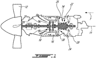
- Fig. 1 illustrates a gas turbine engine 10 of a type preferably provided for use in subsonic flight, and in driving engagement with a rotatable load, which is depicted as a propeller 12.
- the gas turbine engine has in serial flow communication a compressor section 14 for pressurizing the air, a combustor 16 in which the compressed air is mixed with fuel and ignited for generating an annular stream of hot combustion gases, and a turbine section 18 for extracting energy from the combustion gases.
- the compressor section 14 of the gas turbine engine 10 includes an axial compressor 22 and a centrifugal compressor 24 downstream of the axial compressor 22.
- upstream and downstream refer to the direction of an air/gas flow passing through an annular gaspath 20 of the gas turbine engine 10.
- axial refers to a central axis 11 of the annular gaspath 20, which may also be a central axis of gas turbine engine 10.
- the gas turbine engine 10 is depicted as a reverse-flow engine in which the air flows in the annular gaspath 20 from a rear of the gas turbine engine 10 to a front of the gas turbine engine 10 relative to a direction of travel T of the gas turbine engine 10.
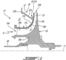
- the centrifugal compressor 24 includes an impeller 26 drivingly engaged by a shaft 28 of the gas turbine engine 10.
- the impeller 26 and the shaft 28 are rotatable about the central axis 11 of the gas turbine engine 10.
- the impeller 26 includes a hub 26a and blades 26b protruding from the hub 26a.
- the blades 26b are circumferentially distributed on the hub 26a about the central axis 11 and protrudes from the hub 26a from a root 26c at the hub 26a to a tip 26d spaced apart from the hub 26a.
- compressed air flowing from the axial compressor 22 flows within a plurality of passages defined between the blades 26b of the impeller 26.
- a impeller housing 30 is disposed around the impeller 26.
- the impeller housing 30 includes a shroud 31 and a structural member 32 secured to the shroud 31 and used to secure the shroud 31 to a casing of the gas turbine engine 10.
- the structural member 32 has an outer end to be secured to the casing of the gas turbine engine 10 and an inner end intersecting the shroud 31.
- the structural member 32 includes an annular wall 32a and an annular flange 32b at a distal end of the annular wall 32a.
- the annular flange 32b is configured to be bolted to a mating flange of the casing of the gas turbine engine 10.
- the shroud 31 is used to substantially limit air from flowing from one of the passages to the next around the tips 26d of the blades 26b.
- the air is contained into the annular gaspath 20, which includes the passages between the blades 26b of the impeller 26, by the hub 26a, the blades 26b, and by the shroud 31.
- the annular gaspath 20 includes the passages between the blades 26b of the impeller 26, by the hub 26a, the blades 26b, and by the shroud 31.
- the shape of the shroud 31 defines the impeller tip clearance.
- the tip clearance is meant to be as small as possible to maximize an amount of air entering the compressor that is being compressed. A clearance of zero would be ideal. However, in reality, there are part growths and movements that occur during engine operation as well as manufacturing tolerances that make this difficult to achieve. Care should be taken to ensure that the blades 26b never rub against the shroud 31 since such a rubbing action may cause a detriment to the engine performance and component life. Reducing the impeller shroud deflection may be a key design requirement in order to minimize tip clearance as discussed below.
- Fig. 2 in use, air enters the passages defined circumferentially between the blades 26b along a streamwise direction depicted by arrow D from an inlet 24a of the impeller 26 to an outlet 24b thereof.
- the streamwise direction is a direction of the flow from the inlet 24a to the outlet 24b of the impeller 26. While the air flows from the inlet 24a to the outlet 24b, it deviates from being mainly axial relative to the central axis 11 to being mainly radial relative to the central axis 11.
- the expression "mainly” as in “mainly axial” implies that a direction is more than 50% axial.
- mainly radial implies that a direction is more than 50% radial.
- a diffuser 25 of the centrifugal compressor 24 is disposed downstream from the outlet 24b of the impeller 26.
- the diffuser 25 may be a suitable pipe diffuser or vane diffuser, for example, which serve to diffuse the air exiting the impeller to further increase the pressure thereof.
- the shroud 31 includes a gaspath side 31a and an opposed rear side 31b, also referred to as cavity side facing away from the annular gaspath 20.
- An opening, such an aperture or a slot 31c is defined by the shroud 31 and extends from the gaspath side 31a through the shroud 31 to the rear side 31b.
- the slot 31c opens to a cavity 33 that is used to receive compressed air bled from the annular gaspath 20 within the centrifugal compressor 24. From the cavity 33, the air bled from the annular gaspath 20 is directed to components, such as bearing housings, that are in need of compressed air for their operation.
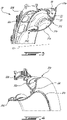
- the housing 30 has a reinforced region shown schematically at 34 in Fig. 2 . This reinforced region 34 may help in alleviate the aforementioned phenomenon as discussed below.
- the housing 30 has thickening or reinforced region 34 at an intersection between the structural member 32 and the shroud 31. In some embodiments this intersection is located at or proximate a knee of the shroud 31.
- the knee of the shroud 31 is a location where a vector normal to the gaspath side 31a of the shroud 31 becomes more axial than radial. That is, a main component of this vector is in a radial direction relative to the central axis 11 from an inlet end 31d of the shroud 31 to the knee. This main component of this vector is in an axial direction relative to the central axis 11 from the knee to an outlet end 31e of the shroud 31.
- the knee corresponds to a point where a radial component of the vector normal to the gaspath side 31a of the shroud 31 is equal to an axial component of the vector.
- the shroud 31 may include an inducer section from an inlet to the knee and an exducer section form the knee to the outlet.
- the reinforced region 34 may extend annularly all around the central axis 11.
- the reinforced region 34 defines a concave portion of the rear side 31b of the shroud 31.
- the intersection between the structural member 32 and the shroud 31 may be located from plus or minus 10% of a length of the shroud 31 from the knee.
- the knee may be located from about 40% to about 60% of the length of the shroud 31 from the inlet end 31d of the shroud 31.
- the intersection may be located at from 30% to 70% of a length of the shroud from the first end, preferably from 40% to 60%.
- the reinforced region 34 defines a curved surface 34a that extends from a first location P1 on the structural member 32 to a second location P2 on the rear side 31b of the shroud 31.
- the intersection between the structural member 32 and the shroud 31 may correspond to a location P3 on the shroud 31 intersected by a projection P4 of the structural member 32 onto the gaspath side 31a of the shroud 31. This location is referred to below as the intersection location P3.
- the intersection is located between the inlet end 31d of the shroud 31 and the outlet end 31e of the shroud 31.
- the outlet end 31e is located radially outwardly of the inlet end 31d relative to the central axis 11. It will be understood that the disclosed shroud 31 may be used as a turbine shroud and the outlet would be located radially inwardly of the inlet.
- the reinforced region 34 is located between the structural member 32 and the outlet end 31e of the shroud 31.
- the reinforced region 34 is meant to increase a stiffness of a radially-outer portion of the shroud 31 that extends radially outwardly beyond the intersection with the structural member 32 and that is cantilevered.
- the reinforced region 34 is located at the intersection since a moment of force exerted by air pressure on the shroud 31 is the greatest at the intersection.
- the reinforced region 34 merges into the rear side 31b of the shroud 31. That is, the shroud 31 has a nominal thickness T that corresponds to a thickness of the shroud 31 without and/or outside the reinforced region 34.
- the nominal thickness T may be taken in a direction normal to the gaspath side 31a of the shroud 31.
- a thickness of the shroud 31 near the inlet end 31d may correspond to the nominal thickness T.
- the thickness of the shroud at a location about midpoint between the inlet end 31d and the structural member 32 may correspond to the nominal thickness T.
- the reinforced region 34 locally increases a thickness of the shroud 31 beyond the nominal thickness T - i.e. the thickness of the reinforced region 34 is greater than the nominal thickness T of the shroud 31.
- the intersection between the structural member 32 and the shroud 31 is closer to the outlet end 31e than to the inlet end 31d of the shroud 31.
- a ratio of a distance D1 between the outlet end 31e and the intersection location P3 between the structural member 32 and the shroud 31 along the gaspath side 31a of the shroud 31 to a length L1 of the shroud 31 from the inlet end 31d to the outlet end 31e along the gaspath side 31a ranges from 0.30 to .90, preferably from 0.50 to 0.80, preferably 0.70.
- the intersection may be located at from 30% to 70% of the length L1 of the shroud 31 from the inlet end 31d.
- the reinforced region 34 defines two zones, namely, a first zone Z1 and a second zone Z2.
- the first zone Z1 is located radially inwardly of the second zone Z2 relative to the central axis 11. More or less than two zones can be use.
- the first zone extends from the first location P1 on the structural member 32 to an intersection between the two zones Z1, Z2.
- the second zone Z2 extends from the first zone Z1 toward the outlet end 31e of the shroud 31 and to the second location P2 on the rear side 31b of the shroud 31.
- both of the first and second zones Z1, Z2 of the reinforced region 34 extends annularly all around the central axis.
- the first zone Z1 has a radius when seen on a plane containing the central axis 11 and intersecting the reinforced region 34.
- the radius of the reinforced region 34 at the first zone Z1 may be constant.
- the radius of the reinforced region 34 changes throughout the second zone Z2. That is, the second zone Z2 has a first radius at the intersection between the first and second zones Z1, Z2.
- the first radius Z1 corresponding to the constant radius of the first zone Z1.
- the second zone Z2 has a second radius where it merges back to the shroud 31.
- the second radius is located at an end of the second zone Z2, which corresponds to the second location P2.
- the second radius corresponds to a radius of the shroud 31 where the thickness of the shroud 31 becomes the nominal thickness T.
- the radius is infinite.
- the expression "radius” is meant to imply the radius of curvature of a curve when taken on a plane containing the central axis 11 and intersecting the reinforced region 34.
- the second zone Z2 may define a Euler's curve, also know as a clothoid, where a radius changes continuously along a length of the second zone Z2 toward the outlet end 31e.
- the radius of the reinforced region Z2 may change (e.g., increase) continuously and monotonically from the first zone Z1 toward the outlet end 31e along the second zone Z2.
- the thickness of the shroud 31 at the reinforced region 34 may continuously and monotonically decrease from the first location P1 to the second location P2.
- the second zone Z2 is used as a transition zone to blend the reinforced region 34 back into the shroud 31.
- the reinforced region 34 may be tangent to the rear side 31b of the shroud 31.
- the reinforced region 34 therefore locally increases a thickness of the shroud 31 beyond the nominal thickness T. This thickness decreases to the nominal thickness T in a direction extending away from the intersection toward the outlet end 31e.
- the thickness of the shroud 31 may therefore be maximal at the first zone Z1.
- the portion of the shroud 31 that extends radially outwardly beyond the intersection with the structural member 32 has a radial height H1 taken in a radial direction relative to the central axis 11.
- the radial height H1 starts from the intersection location P3 on the shroud 31 and ends at the outlet end 31e of the shroud 31.
- the second location P2 where the reinforced region 34 merges back to the rear side 31b of the shroud 31 may be located closer to the outlet end 31e than to the intersection location P3.
- the second location P2 is selected to minimize weight without compromising its reinforcement function.
- the second location P2 is selected in function of the thickness of the shroud 31, pressure distribution on the shroud 31, operating conditions of the centrifugal compressor 24, as well as a stiffness of the material selected for the shroud 31.
- the second location P2 may register with the outlet end 31e.
- a ratio of a distance D2 from the intersection location P3 to the second location P2 to the radial height H1 of the portion of the shroud 31 that extends radially outwardly beyond the intersection is at least about 0.25 and at most 1, preferably at least about 0.3 and, in some cases, from 0.30 to 0.60. Stated differently, a ratio of a radial distance D3 relative to the central axis 11 from the outlet end 31e of the shroud 31 to the second location P2 to the radial height H1 is at most 0.8, preferably at most 0.75.
- the first zone Z1 has a constant radius that may range from 10% to 40%, preferably from 17% to 35% of the radial height H1 of the portion of the shroud 31 that extends radially outwardly beyond the intersection.
- the shroud 31 includes a protrusion 31f at the outlet end 31e.
- the protrusion 31f is annular and extends all around the central axis 11. As shown, the protrusion 31f extends from the rear side 31b of the shroud 31 and away from the gaspath side 31a. The protrusion 31f may therefore be outside the annular gaspath 20 ( Fig. 1 )
- a thickness of the shroud 31 at the protrusion 31f may be from about 10% to about 300% greater than the nominal thickness T.
- the protrusion 31f may help in increasing a stiffness of the shroud 31 at the outlet end 31e to minimize pressure-induced deflection.
- the protrusion 31f is used to shift a dynamic response frequency of the portion of the shroud 31 that extends radially-outwardly from the intersection with the structural member 32 out of an operating range of excitation frequencies.
- the thickness of the shroud 31 at the outlet end 31e is 25% greater than the nominal thickness T.
- FIG. 7 another embodiment of a housing is shown at 130.
- the housing 130 For the sake of conciseness, only elements of the housing 130 that differ from the impeller housing 30 described above with reference to Figs. 3-6 are described below.
- the housing 130 includes a reinforced region 134 at the intersection between the structural member 32 and the shroud 31.
- the reinforced region 134 extends from the first location P1 on the structural member 32 to the second location P2 on the rear side 31b of the shroud 31.
- the reinforced region 134 has a constant radius from the first location P1 to the second location P2.
- the radius of the reinforced region 134 may be from 10% to 40%, preferably from 17% to 35% of the radial height H1 of the portion of the shroud 31 that extends radially outwardly beyond the intersection.
- a ratio of a distance D2 from the intersection location P3 to the second location P2 to the radial height H1 of the portion of the shroud 31 that extends radially outwardly beyond the intersection is at least about 0.20 and at most 1, preferably from 0.30 to 0.60.
- the outline O1 shows a configuration in which no reinforced region is used.
- the outline O1 therefore depicts a simple fillet, which may be created as a result of a diameter of a machining tool used for milling the housing 130.
- the disclosed housings 30, 130 have a reinforced region 34, 134 that extends beyond a baseline fillet and beyond the outline O1.
- the fillet connects to the rear side 31b of the shroud 31 at a location that is close to the structural member 32 leaving a majority (e.g., more than 80%) of the portion of the shroud 31 that extends beyond the structural member 32 at the nominal thickness T, free of reinforcement, and subjected to the drawbacks disclosed above.
- the disclosed reinforced regions 34, 134 connect to the rear side 31b of the shroud 31 at a location being at least 20-25% of the radial height H1, whereas a fillet connects the shroud at a location being at most 5-10% of the radial height H1.
- a baseline fillet O1 may not be able to offer the added structural support needed to limit deflection of the outlet end 31e of the shroud 31.
- the impeller housing 30 may be manufactured by multiple machining steps.
- the part may be turned to create a rough shape as well as several final surfaces. Holes and slots may then milled be into the part.
- weight reduction can be achieved by thinning of various regions but, this must not result in deflections that compromise the impeller shroud's tip clearance.
- the shroud 31 of the present disclosure includes a reinforced region 34, 134 that allows to locally reinforce the shroud so that it may withstand the forces imparted thereto by air flowing through the centrifugal compressor, but by limiting added weight to the shroud 31.
- a gradual tapering of material at the impeller housing knee may be implemented in locations where the highest deflections are expected, such as the outlet end 31e of the impeller housing 30, a gradual tapering of material at the impeller housing knee may be implemented. This gradual tapering may reduce the deflection of the shroud 31 compared to a configuration without the reinforced region. Thickening and thinning of the impeller housing may allow the fine tuning of the housing properties such as dynamic response, part deflections and weight reduction.
- the expression "about” implies a variation by plus or minus 10% of a value.
- about 10 includes values from 9 to 11.
Landscapes
- Engineering & Computer Science (AREA)
- Mechanical Engineering (AREA)
- General Engineering & Computer Science (AREA)
- Structures Of Non-Positive Displacement Pumps (AREA)
Abstract
Description
- The present disclosure relates generally to centrifugal compressors and turbines of gas turbine engines and, more particularly, to housings disposed around impellers of such centrifugal fluid machines.
- A centrifugal fluid machine, such as a centrifugal compressor, generally includes an impeller which rotates within a housing disposed around the impeller. The impeller includes a hub mounted to a drive shaft so as to be rotated therewith. Vanes (i.e., blades) of the impeller extend from the hub and are typically arranged to redirect an axially-directed inbound gas flow radially outwardly. The housing is disposed as close as possible to tips of the blades such as to minimize tip clearance and thereby maximize an amount of a fluid being worked on by the impeller. Stresses may however be imparted on the housing, such as a result of the pressure of the fluid flowing through the impeller. These stresses can locally vary the tip clearance, which can impair efficiency of the machine. Such stresses may be higher at an exit of the impeller, where the pressure is greatest. Improvements are therefore sought.
- In one aspect, there is provided a centrifugal compressor for a gas turbine engine, comprising: an impeller having blades extending from a hub to blade tips, the impeller having an inlet and an outlet; and a housing disposed around the impeller, the impeller rotatable relative to the housing about a central axis, the housing including: a shroud annularly extending around the blade tips of the impeller and extending in a streamwise direction (i.e., a direction of air flow from the impeller inlet to the impeller outlet) between a first end proximate the inlet of the impeller and a second end proximate the outlet of the impeller, the shroud having a gaspath side facing the impeller and a rear side opposed to the gaspath side; a structural member supporting the shroud, the structural member having an outer end securable to a casing of the gas turbine engine, an inner end of the structural member intersecting the rear side of the shroud at a location between the first end and the second end; and a reinforced region at the location where the structural member and the rear side of the shroud intersect, a thickness of the reinforced region in a direction normal to the gaspath side being greater than a nominal thickness of the shroud outside the reinforced region, the reinforced region defining a curved surface extending from a first location on the structural member to a second location on the rear side of the shroud, the second location being disposed between the structural member and the second end of the shroud, a portion of the curved surface having a radius that increases from a first radius to a second radius at the second location.
- The centrifugal compressor as defined above and herein may further include, in whole or in part, and in any combination, one or more of the following features.
- In some embodiments, the portion of the curved surface is a second zone of the curved surface, the curved surface having a first zone extending from the first location to the second zone, the first zone having a constant radius.
- In some embodiments, the shroud has a radially-outer portion extending from a projection of the structural member on the gaspath side to the second end, the radially-outer portion having a radial height from the projection to the second end along a radial direction relative to the central axis, a radius of the first zone ranging from 10% to 40% of the radial height.
- In some embodiments, the first radius (or radius of the first zone) ranges from 17% to 35% of the radial height.
- In some embodiments, the portion of the curved surface merges into the shroud toward the second end of the shroud.
- In some embodiments, the thickness of the shroud is maximal at the first location of the reinforced region and decreases to the nominal thickness toward the second end of the shroud.
- In some embodiments, the thickness continuously and monotonically decreases from the first location to the second location.
- In some embodiments, the thickness reaches the nominal thickness between the inner end of the structural member and the second end.
- In some embodiments, the second location is closer to the second end than to the inner end of the structural member.
- In some embodiments, the shroud has a radially-outer portion extending radially outwardly from a projection of the structural member on the gaspath side to the second end, the radially-outer portion having a radial height from the projection to the second end along a radial direction relative to the central axis, the second location being at at least 20% of the radial height from the projection.
- In some embodiments, an intersection between the structural member and the rear side of the shroud is located proximate a knee of the shroud, the knee corresponding to a point where a radial component of a vector normal to the gaspath side of the shroud is equal to an axial component of the vector.
- In some embodiments, the intersection is located at from 30% to 70% of a length of the shroud from the first end, the length of the shroud extending from the first end to the second end along the gaspath side.
- In another aspect, there is provided an impeller housing for an impeller of a centrifugal compressor of a gas turbine engine, comprising: a shroud annularly extending around a central axis, the shroud having a gaspath side facing the central axis and an opposed rear side, the shroud having a first end proximate an inlet of the impeller and a second end proximate an outlet of the compressor; a structural member supporting the shroud, the structural member having an outer end securable to a casing of the gas turbine engine, an inner end of the structural member intersecting the rear side of the shroud at a location between the first end and the second end; and a reinforced region at the location where the structural member and the rear side of the shroud intersect, a thickness of the reinforced region in a direction normal to the gaspath side greater than a nominal thickness of the shroud outside the reinforced region, the reinforced region extending from a first location on the structural member to a second location on the rear side of the shroud, the second location between the structural member and the second end, a ratio of a radial distance (D3) relative to the central axis from the second end to the second location to a radial height (H1) of a portion of the shroud that extends radially outwardly beyond the inner end of the structural member being at most 0.8.
- The an impeller housing for an impeller of a centrifugal compressor as defined above and herein may further include, in whole or in part, and in any combination, one or more of the following features.
- In some embodiments, a radius of the reinforced region ranges from 10% to 40% of the radial height.
- In some embodiments, the first radius ranges from 17% to 35% of the radial height.
- In some embodiments, the portion extends from a projection of the structural member on the gaspath side of the shroud to the second end.
- In some embodiments, a thickness of the shroud taken in a direction normal to the gaspath side is maximal at the first location and decreases to a nominal thickness toward the second end of the shroud.
- In some embodiments, the thickness continuously and monotonically decreases from the first location to the second location.
- In some embodiments, an intersection between the structural member and the rear side of the shroud is located proximate a knee of the shroud, the knee corresponding to a point where a radial component of a vector normal to the gaspath side of the shroud is equal to an axial component of the vector.
- In some embodiments, the intersection is located at from 30% to 70% of a length of the shroud from the first end, the length of the shroud extending from the first end to the second end along the gaspath side.
- Reference is now made to the accompanying figures in which:
-
Fig. 1 is a schematic cross sectional view of a gas turbine engine; -
Fig. 2 is a schematic cross-sectional view of a centrifugal compressor of the engine ofFig. 1 ; -
Fig. 3 is a three dimensional cutaway view of a shroud in accordance with one embodiment disposed around an impeller of the centrifugal compressor ofFig. 2 ; -
Fig. 4 is another three dimensional cutaway view of the shroud ofFig. 3 illustrated at a different angle; -
Fig. 5 is a cross-sectional view of the shroud ofFig. 3 ; -
Fig. 6 is an enlarged view of a portion ofFig. 5 ; and -
Fig. 7 is a cross-sectional view of a portion of a shroud in accordance with another embodiment. - The following disclosure relates generally to gas turbine engines, and more particularly to centrifugal fluid machines, such as compressor and turbines, that may be present in a compressor section and/or a turbine section of a gas turbine engine. In some embodiments, the assemblies and methods disclosed herein promote better performance of gas turbine engines, such as by improving flow conditions in the compressor section and/or turbine section in some operating conditions, improving the operable range of the compressor/turbine, and reducing energy losses.
-
Fig. 1 illustrates a gas turbine engine 10 of a type preferably provided for use in subsonic flight, and in driving engagement with a rotatable load, which is depicted as apropeller 12. The gas turbine engine has in serial flow communication acompressor section 14 for pressurizing the air, acombustor 16 in which the compressed air is mixed with fuel and ignited for generating an annular stream of hot combustion gases, and aturbine section 18 for extracting energy from the combustion gases. In the embodiment shown, thecompressor section 14 of the gas turbine engine 10 includes anaxial compressor 22 and acentrifugal compressor 24 downstream of theaxial compressor 22. - It should be noted that the terms "upstream" and "downstream" used herein refer to the direction of an air/gas flow passing through an
annular gaspath 20 of the gas turbine engine 10. It should also be noted that the term "axial", "radial", "angular" and "circumferential" are used with respect to acentral axis 11 of theannular gaspath 20, which may also be a central axis of gas turbine engine 10. The gas turbine engine 10 is depicted as a reverse-flow engine in which the air flows in theannular gaspath 20 from a rear of the gas turbine engine 10 to a front of the gas turbine engine 10 relative to a direction of travel T of the gas turbine engine 10. This is opposite than a through-flow engine in which the air flows within theannular gaspath 20 in a direction opposite the direction of travel T, from the front of the engine towards the rear of the gas turbine engine 10. The principles of the present disclosure may apply to reverse-flow and through-flow engines and to any other gas turbine engines, such as a turbofan engine and a turboprop engine. - Referring to
Fig. 2 , thecentrifugal compressor 24 includes animpeller 26 drivingly engaged by ashaft 28 of the gas turbine engine 10. Theimpeller 26 and theshaft 28 are rotatable about thecentral axis 11 of the gas turbine engine 10. Theimpeller 26 includes ahub 26a andblades 26b protruding from thehub 26a. Theblades 26b are circumferentially distributed on thehub 26a about thecentral axis 11 and protrudes from thehub 26a from aroot 26c at thehub 26a to atip 26d spaced apart from thehub 26a. In use, compressed air flowing from theaxial compressor 22 flows within a plurality of passages defined between theblades 26b of theimpeller 26. Aimpeller housing 30 is disposed around theimpeller 26. Theimpeller housing 30 includes ashroud 31 and astructural member 32 secured to theshroud 31 and used to secure theshroud 31 to a casing of the gas turbine engine 10. Namely, thestructural member 32 has an outer end to be secured to the casing of the gas turbine engine 10 and an inner end intersecting theshroud 31. In the embodiment shown, thestructural member 32 includes anannular wall 32a and anannular flange 32b at a distal end of theannular wall 32a. Theannular flange 32b is configured to be bolted to a mating flange of the casing of the gas turbine engine 10. Theshroud 31 is used to substantially limit air from flowing from one of the passages to the next around thetips 26d of theblades 26b. In other words, the air is contained into theannular gaspath 20, which includes the passages between theblades 26b of theimpeller 26, by thehub 26a, theblades 26b, and by theshroud 31. To be as efficient as possible, it is desired to minimize as much as possible a gap, or tip clearance, between thetips 26d of theblades 26b and theshroud 31. - The shape of the
shroud 31 defines the impeller tip clearance. The tip clearance is meant to be as small as possible to maximize an amount of air entering the compressor that is being compressed. A clearance of zero would be ideal. However, in reality, there are part growths and movements that occur during engine operation as well as manufacturing tolerances that make this difficult to achieve. Care should be taken to ensure that theblades 26b never rub against theshroud 31 since such a rubbing action may cause a detriment to the engine performance and component life. Reducing the impeller shroud deflection may be a key design requirement in order to minimize tip clearance as discussed below. - Still referring to
Fig. 2 , in use, air enters the passages defined circumferentially between theblades 26b along a streamwise direction depicted by arrow D from aninlet 24a of theimpeller 26 to anoutlet 24b thereof. The streamwise direction is a direction of the flow from theinlet 24a to theoutlet 24b of theimpeller 26. While the air flows from theinlet 24a to theoutlet 24b, it deviates from being mainly axial relative to thecentral axis 11 to being mainly radial relative to thecentral axis 11. Herein, the expression "mainly" as in "mainly axial" implies that a direction is more than 50% axial. Similarly, "mainly radial" implies that a direction is more than 50% radial. The principles of the present disclosure apply to any centrifugal fluid machine, such as a centrifugal compressor as discussed below or a centrifugal turbine. As seen inFig. 1 , adiffuser 25 of thecentrifugal compressor 24 is disposed downstream from theoutlet 24b of theimpeller 26. Thediffuser 25 may be a suitable pipe diffuser or vane diffuser, for example, which serve to diffuse the air exiting the impeller to further increase the pressure thereof. - The
shroud 31 includes agaspath side 31a and an opposedrear side 31b, also referred to as cavity side facing away from theannular gaspath 20. An opening, such an aperture or aslot 31c (Fig. 3 ) is defined by theshroud 31 and extends from thegaspath side 31a through theshroud 31 to therear side 31b. Theslot 31c opens to acavity 33 that is used to receive compressed air bled from theannular gaspath 20 within thecentrifugal compressor 24. From thecavity 33, the air bled from theannular gaspath 20 is directed to components, such as bearing housings, that are in need of compressed air for their operation. - In use, pressure of the air flowing through the
centrifugal compressor 24 increases as the air moves radially outwardly away from thecentral axis 11 and toward theoutlet 24b of thecentrifugal compressor 24. As pressure increases, more force is applied on thegaspath side 31a of theshroud 31. This may deform theshroud 31 thereby increasing the radial gap between theshroud 31 at thegaspath side 31a and thetips 26d of theblades 26b. This may impair efficiency of an impeller. This may be caused by a portion of theshroud 31 being cantilevered from thestructural member 32. Thepresent shroud 31 has features that will be described herein below that may at least partially alleviate this phenomenon. Namely, thehousing 30 has a reinforced region shown schematically at 34 inFig. 2 . This reinforcedregion 34 may help in alleviate the aforementioned phenomenon as discussed below. - Referring now to
Figs. 3-6 , thehousing 30 has thickening or reinforcedregion 34 at an intersection between thestructural member 32 and theshroud 31. In some embodiments this intersection is located at or proximate a knee of theshroud 31. The knee of theshroud 31 is a location where a vector normal to thegaspath side 31a of theshroud 31 becomes more axial than radial. That is, a main component of this vector is in a radial direction relative to thecentral axis 11 from aninlet end 31d of theshroud 31 to the knee. This main component of this vector is in an axial direction relative to thecentral axis 11 from the knee to anoutlet end 31e of theshroud 31. In other words, the knee corresponds to a point where a radial component of the vector normal to thegaspath side 31a of theshroud 31 is equal to an axial component of the vector. Still in yet other words, theshroud 31 may include an inducer section from an inlet to the knee and an exducer section form the knee to the outlet. The reinforcedregion 34 may extend annularly all around thecentral axis 11. The reinforcedregion 34 defines a concave portion of therear side 31b of theshroud 31. The intersection between thestructural member 32 and theshroud 31 may be located from plus or minus 10% of a length of theshroud 31 from the knee. The knee may be located from about 40% to about 60% of the length of theshroud 31 from theinlet end 31d of theshroud 31. The intersection may be located at from 30% to 70% of a length of the shroud from the first end, preferably from 40% to 60%. - Referring more particularly to
Figs. 5-6 , the reinforcedregion 34 defines acurved surface 34a that extends from a first location P1 on thestructural member 32 to a second location P2 on therear side 31b of theshroud 31. The intersection between thestructural member 32 and theshroud 31 may correspond to a location P3 on theshroud 31 intersected by a projection P4 of thestructural member 32 onto thegaspath side 31a of theshroud 31. This location is referred to below as the intersection location P3. The intersection is located between theinlet end 31d of theshroud 31 and theoutlet end 31e of theshroud 31. Theoutlet end 31e is located radially outwardly of theinlet end 31d relative to thecentral axis 11. It will be understood that the disclosedshroud 31 may be used as a turbine shroud and the outlet would be located radially inwardly of the inlet. - The reinforced
region 34 is located between thestructural member 32 and theoutlet end 31e of theshroud 31. The reinforcedregion 34 is meant to increase a stiffness of a radially-outer portion of theshroud 31 that extends radially outwardly beyond the intersection with thestructural member 32 and that is cantilevered. In the embodiment shown, the reinforcedregion 34 is located at the intersection since a moment of force exerted by air pressure on theshroud 31 is the greatest at the intersection. The reinforcedregion 34 merges into therear side 31b of theshroud 31. That is, theshroud 31 has a nominal thickness T that corresponds to a thickness of theshroud 31 without and/or outside the reinforcedregion 34. The nominal thickness T may be taken in a direction normal to thegaspath side 31a of theshroud 31. In one particular embodiment, a thickness of theshroud 31 near theinlet end 31d may correspond to the nominal thickness T. In another embodiment, the thickness of the shroud at a location about midpoint between theinlet end 31d and thestructural member 32 may correspond to the nominal thickness T. Regardless, the reinforcedregion 34 locally increases a thickness of theshroud 31 beyond the nominal thickness T - i.e. the thickness of the reinforcedregion 34 is greater than the nominal thickness T of theshroud 31. - In the embodiment shown, the intersection between the
structural member 32 and theshroud 31 is closer to theoutlet end 31e than to theinlet end 31d of theshroud 31. A ratio of a distance D1 between theoutlet end 31e and the intersection location P3 between thestructural member 32 and theshroud 31 along thegaspath side 31a of theshroud 31 to a length L1 of theshroud 31 from theinlet end 31d to theoutlet end 31e along thegaspath side 31a ranges from 0.30 to .90, preferably from 0.50 to 0.80, preferably 0.70. In other words, the intersection may be located at from 30% to 70% of the length L1 of theshroud 31 from theinlet end 31d. - Referring more particularly to
Fig. 6 , the reinforcedregion 34 defines two zones, namely, a first zone Z1 and a second zone Z2. The first zone Z1 is located radially inwardly of the second zone Z2 relative to thecentral axis 11. More or less than two zones can be use. The first zone extends from the first location P1 on thestructural member 32 to an intersection between the two zones Z1, Z2. The second zone Z2 extends from the first zone Z1 toward theoutlet end 31e of theshroud 31 and to the second location P2 on therear side 31b of theshroud 31. In the embodiment shown, both of the first and second zones Z1, Z2 of the reinforcedregion 34 extends annularly all around the central axis. - The first zone Z1 has a radius when seen on a plane containing the
central axis 11 and intersecting the reinforcedregion 34. The radius of the reinforcedregion 34 at the first zone Z1 may be constant. The radius of the reinforcedregion 34 changes throughout the second zone Z2. That is, the second zone Z2 has a first radius at the intersection between the first and second zones Z1, Z2. The first radius Z1 corresponding to the constant radius of the first zone Z1. The second zone Z2 has a second radius where it merges back to theshroud 31. The second radius is located at an end of the second zone Z2, which corresponds to the second location P2. The second radius corresponds to a radius of theshroud 31 where the thickness of theshroud 31 becomes the nominal thickness T. If therear side 31b of theshroud 31 is straight at the second location P2, the radius is infinite. In the context of the present disclosure, the expression "radius" is meant to imply the radius of curvature of a curve when taken on a plane containing thecentral axis 11 and intersecting the reinforcedregion 34. - The second zone Z2 may define a Euler's curve, also know as a clothoid, where a radius changes continuously along a length of the second zone Z2 toward the
outlet end 31e. The radius of the reinforced region Z2 may change (e.g., increase) continuously and monotonically from the first zone Z1 toward theoutlet end 31e along the second zone Z2. The thickness of theshroud 31 at the reinforcedregion 34 may continuously and monotonically decrease from the first location P1 to the second location P2. The second zone Z2 is used as a transition zone to blend the reinforcedregion 34 back into theshroud 31. The reinforcedregion 34 may be tangent to therear side 31b of theshroud 31. The reinforcedregion 34 therefore locally increases a thickness of theshroud 31 beyond the nominal thickness T. This thickness decreases to the nominal thickness T in a direction extending away from the intersection toward theoutlet end 31e. The thickness of theshroud 31 may therefore be maximal at the first zone Z1. - Still referring more particularly to
Fig. 6 , the portion of theshroud 31 that extends radially outwardly beyond the intersection with thestructural member 32 has a radial height H1 taken in a radial direction relative to thecentral axis 11. The radial height H1 starts from the intersection location P3 on theshroud 31 and ends at theoutlet end 31e of theshroud 31. In the embodiment shown, the second location P2 where the reinforcedregion 34 merges back to therear side 31b of theshroud 31 may be located closer to theoutlet end 31e than to the intersection location P3. The second location P2 is selected to minimize weight without compromising its reinforcement function. The second location P2 is selected in function of the thickness of theshroud 31, pressure distribution on theshroud 31, operating conditions of thecentrifugal compressor 24, as well as a stiffness of the material selected for theshroud 31. In an embodiment, the second location P2 may register with theoutlet end 31e. - A ratio of a distance D2 from the intersection location P3 to the second location P2 to the radial height H1 of the portion of the
shroud 31 that extends radially outwardly beyond the intersection is at least about 0.25 and at most 1, preferably at least about 0.3 and, in some cases, from 0.30 to 0.60. Stated differently, a ratio of a radial distance D3 relative to thecentral axis 11 from theoutlet end 31e of theshroud 31 to the second location P2 to the radial height H1 is at most 0.8, preferably at most 0.75. In the embodiment shown, the first zone Z1 has a constant radius that may range from 10% to 40%, preferably from 17% to 35% of the radial height H1 of the portion of theshroud 31 that extends radially outwardly beyond the intersection. - In the embodiment shown, the
shroud 31 includes aprotrusion 31f at theoutlet end 31e. In the present embodiment, theprotrusion 31f is annular and extends all around thecentral axis 11. As shown, theprotrusion 31f extends from therear side 31b of theshroud 31 and away from thegaspath side 31a. Theprotrusion 31f may therefore be outside the annular gaspath 20 (Fig. 1 ) A thickness of theshroud 31 at theprotrusion 31f may be from about 10% to about 300% greater than the nominal thickness T. Theprotrusion 31f may help in increasing a stiffness of theshroud 31 at theoutlet end 31e to minimize pressure-induced deflection. Theprotrusion 31f is used to shift a dynamic response frequency of the portion of theshroud 31 that extends radially-outwardly from the intersection with thestructural member 32 out of an operating range of excitation frequencies. In the present case, the thickness of theshroud 31 at theoutlet end 31e is 25% greater than the nominal thickness T. - Referring now to
Fig. 7 , another embodiment of a housing is shown at 130. For the sake of conciseness, only elements of thehousing 130 that differ from theimpeller housing 30 described above with reference toFigs. 3-6 are described below. - The
housing 130 includes a reinforcedregion 134 at the intersection between thestructural member 32 and theshroud 31. The reinforcedregion 134 extends from the first location P1 on thestructural member 32 to the second location P2 on therear side 31b of theshroud 31. In the embodiment shown, the reinforcedregion 134 has a constant radius from the first location P1 to the second location P2. The radius of the reinforcedregion 134 may be from 10% to 40%, preferably from 17% to 35% of the radial height H1 of the portion of theshroud 31 that extends radially outwardly beyond the intersection. A ratio of a distance D2 from the intersection location P3 to the second location P2 to the radial height H1 of the portion of theshroud 31 that extends radially outwardly beyond the intersection is at least about 0.20 and at most 1, preferably from 0.30 to 0.60. - As shown in
Fig. 7 , a plurality of possible reinforced regions each having a respective constant radius are shown with dashed lines. The outline O1 shows a configuration in which no reinforced region is used. The outline O1 therefore depicts a simple fillet, which may be created as a result of a diameter of a machining tool used for milling thehousing 130. The disclosedhousings region rear side 31b of theshroud 31 at a location that is close to thestructural member 32 leaving a majority (e.g., more than 80%) of the portion of theshroud 31 that extends beyond thestructural member 32 at the nominal thickness T, free of reinforcement, and subjected to the drawbacks disclosed above. The disclosed reinforcedregions rear side 31b of theshroud 31 at a location being at least 20-25% of the radial height H1, whereas a fillet connects the shroud at a location being at most 5-10% of the radial height H1. Hence, a baseline fillet O1 may not be able to offer the added structural support needed to limit deflection of theoutlet end 31e of theshroud 31. - The
impeller housing 30 may be manufactured by multiple machining steps. The part may be turned to create a rough shape as well as several final surfaces. Holes and slots may then milled be into the part. As a relatively large part, weight reduction can be achieved by thinning of various regions but, this must not result in deflections that compromise the impeller shroud's tip clearance. Theshroud 31 of the present disclosure includes a reinforcedregion shroud 31. That is, in locations where the highest deflections are expected, such as theoutlet end 31e of theimpeller housing 30, a gradual tapering of material at the impeller housing knee may be implemented. This gradual tapering may reduce the deflection of theshroud 31 compared to a configuration without the reinforced region. Thickening and thinning of the impeller housing may allow the fine tuning of the housing properties such as dynamic response, part deflections and weight reduction. - In the context of the present disclosure, the expression "about" implies a variation by plus or minus 10% of a value. For instance, about 10 includes values from 9 to 11.
- The embodiments described in this document provide non-limiting examples of possible implementations of the present technology. Upon review of the present disclosure, a person of ordinary skill in the art will recognize that changes may be made to the embodiments described herein without departing from the scope of the present technology. For example, features of the shrouds disclosed in the present disclosure may be applied to a shroud of a centrifugal turbine. Yet further modifications could be implemented by a person of ordinary skill in the art in view of the present disclosure, which modifications would be within the scope of the present technology.
Claims (13)
- A centrifugal compressor (24) for a gas turbine engine (10), comprising:an impeller (26) having blades (26b) extending from a hub (26a) to blade tips (26d), the impeller (26) having an inlet (24a) and an outlet (24b); anda housing (30;130) disposed around the impeller (26), the impeller (26) rotatable relative to the housing (30;130) about a central axis (11), the housing (30) including:a shroud (31) annularly extending around the blade tips (26d) of the impeller (26) and extending in a streamwise direction (D) between a first end (31d) proximate the inlet (24a) of the impeller (26) and a second end (31e) proximate the outlet (24b) of the impeller (26), the shroud (31) having a gaspath side (31a) facing the impeller (26) and a rear side (31b) opposed to the gaspath side (31a);a structural member (32) supporting the shroud (31), the structural member (32) having an outer end securable to a casing of the gas turbine engine (10), an inner end of the structural member (32) intersecting the rear side (31b) of the shroud (31) at a location between the first end (31d) and the second end (31e); anda reinforced region (34;134) at the location where the structural member (32) and the rear side (31b) of the shroud (31) intersect, a thickness of the reinforced region (34;134) in a direction normal to the gaspath side (31a) being greater than a nominal thickness (T) of the shroud (31) outside the reinforced region (34;134), the reinforced region (34;134) defining a curved surface (34a) extending from a first location (P1) on the structural member (32) to a second location (P2) on the rear side (31b) of the shroud (31), the second location (P2) being disposed between the structural member (32) and the second end (31e) of the shroud (31), a portion of the curved surface (34a) having a radius that increases from a first radius to a second radius at the second location (P2).
- The centrifugal compressor (24) of claim 1, wherein the curved surface (34a) has a first zone (Z1) and a second zone (Z2), the portion of the curved surface (34a) is the second zone (Z2) of the curved surface (34a), the first zone (Z1) extending from the first location (P1) to the second zone (Z2), the first zone (Z1) having a constant radius.
- The centrifugal compressor (24) of claim 2, wherein the shroud (31) has a radially-outer portion extending from a projection (P4) of the structural member (32) on the gaspath side (31a) to the second end (31e), the radially-outer portion having a radial height (H1) from the projection (P4) to the second end (31e) along a radial direction relative to the central axis (11), the radius of the first zone (Z1) ranging from 10% to 40% of the radial height (H1).
- The centrifugal compressor (24) of claim 3, wherein the first radius ranges from 17% to 35% of the radial height (H1).
- The centrifugal compressor (24) of claim 3 or 4, wherein the second location (P2) is at at least 20% of the radial height (H1) from the projection (P4).
- The centrifugal compressor (24) of any preceding claim, wherein the portion of the curved surface (34a) merges into the shroud (31) toward the second end (31e) of the shroud (31).
- The centrifugal compressor (24) of any preceding claim, wherein the thickness of the shroud (31) is maximal at the first location (P1) of the reinforced region (34;134) and decreases to the nominal thickness (T) toward the second end of the shroud (31).
- The centrifugal compressor (24) of any preceding claim, wherein the thickness continuously and monotonically decreases from the first location (P1) to the second location (P2).
- The centrifugal compressor (24) of any preceding claim, wherein the thickness reaches the nominal thickness (T) between the inner end of the structural member (32) and the second end (31e).
- The centrifugal compressor (24) of any preceding claim, wherein the second location (P2) is closer to the second end (31e) than to the inner end of the structural member (32).
- The centrifugal compressor (24) of any preceding claim, wherein an intersection between the structural member (32) and the rear side (31b) of the shroud (31) is located proximate a knee of the shroud (31), the knee corresponding to a point where a radial component of a vector normal to the gaspath side (31a) of the shroud (31) is equal to an axial component of the vector.
- The centrifugal compressor (24) of claim 11, wherein the intersection is located at from 30% to 70% of a length of the shroud (31) from the first end (31d), the length of the shroud (31) extending from the first end (31d) to the second end (31e) along the gaspath side (31a).
- The centrifugal compressor (24) of any preceding claim, wherein a ratio of a radial distance (D3) relative to the central axis (11), from the second end (31e) to the second location (P2), to a or the radial height (H1) of a portion of the shroud (31) that extends radially outwardly beyond the inner end of the structural member (32) is at most 0.8.
Applications Claiming Priority (1)
| Application Number | Priority Date | Filing Date | Title |
|---|---|---|---|
| US17/180,262 US11885338B2 (en) | 2021-02-19 | 2021-02-19 | Housing for a centrifugal compressor |
Publications (1)
| Publication Number | Publication Date |
|---|---|
| EP4047188A1 true EP4047188A1 (en) | 2022-08-24 |
Family
ID=80953392
Family Applications (1)
| Application Number | Title | Priority Date | Filing Date |
|---|---|---|---|
| EP22157610.1A Pending EP4047188A1 (en) | 2021-02-19 | 2022-02-18 | Housing for a centrifugal compressor |
Country Status (3)
| Country | Link |
|---|---|
| US (1) | US11885338B2 (en) |
| EP (1) | EP4047188A1 (en) |
| CA (1) | CA3146083A1 (en) |
Cited By (1)
| Publication number | Priority date | Publication date | Assignee | Title |
|---|---|---|---|---|
| EP4137703A1 (en) * | 2021-08-20 | 2023-02-22 | Pratt & Whitney Canada Corp. | Impeller shroud frequency tuning rib |
Citations (4)
| Publication number | Priority date | Publication date | Assignee | Title |
|---|---|---|---|---|
| US4264271A (en) * | 1979-03-15 | 1981-04-28 | Avco Corporation | Impeller shroud of a centrifugal compressor |
| US5555721A (en) * | 1994-09-28 | 1996-09-17 | General Electric Company | Gas turbine engine cooling supply circuit |
| US20130202428A1 (en) * | 2010-10-21 | 2013-08-08 | Turbomeca | Method for attaching the cover of a centrifugal compressor of a turbine engine, compressor cover implementing same and compressor assembly provided with such a cover |
| FR2987874A1 (en) * | 2012-03-09 | 2013-09-13 | Snecma | Lid for covering top part of blades of rotor of compressor of turbojet in business aircraft, has two portions formed different from each other and designed as complementary parts for covering compressor by assembling blades |
Family Cites Families (2)
| Publication number | Priority date | Publication date | Assignee | Title |
|---|---|---|---|---|
| JP2017530299A (en) * | 2014-10-07 | 2017-10-12 | ゼネラル・エレクトリック・カンパニイ | Boundary layer control of the diffuser passage of a centrifugal compressor |
| US10704560B2 (en) * | 2018-06-13 | 2020-07-07 | Rolls-Royce Corporation | Passive clearance control for a centrifugal impeller shroud |
-
2021
- 2021-02-19 US US17/180,262 patent/US11885338B2/en active Active
-
2022
- 2022-01-18 CA CA3146083A patent/CA3146083A1/en active Pending
- 2022-02-18 EP EP22157610.1A patent/EP4047188A1/en active Pending
Patent Citations (4)
| Publication number | Priority date | Publication date | Assignee | Title |
|---|---|---|---|---|
| US4264271A (en) * | 1979-03-15 | 1981-04-28 | Avco Corporation | Impeller shroud of a centrifugal compressor |
| US5555721A (en) * | 1994-09-28 | 1996-09-17 | General Electric Company | Gas turbine engine cooling supply circuit |
| US20130202428A1 (en) * | 2010-10-21 | 2013-08-08 | Turbomeca | Method for attaching the cover of a centrifugal compressor of a turbine engine, compressor cover implementing same and compressor assembly provided with such a cover |
| FR2987874A1 (en) * | 2012-03-09 | 2013-09-13 | Snecma | Lid for covering top part of blades of rotor of compressor of turbojet in business aircraft, has two portions formed different from each other and designed as complementary parts for covering compressor by assembling blades |
Cited By (1)
| Publication number | Priority date | Publication date | Assignee | Title |
|---|---|---|---|---|
| EP4137703A1 (en) * | 2021-08-20 | 2023-02-22 | Pratt & Whitney Canada Corp. | Impeller shroud frequency tuning rib |
Also Published As
| Publication number | Publication date |
|---|---|
| US11885338B2 (en) | 2024-01-30 |
| US20220268285A1 (en) | 2022-08-25 |
| CA3146083A1 (en) | 2022-08-19 |
Similar Documents
| Publication | Publication Date | Title |
|---|---|---|
| US6361277B1 (en) | Methods and apparatus for directing airflow to a compressor bore | |
| US6837679B2 (en) | Gas turbine engine | |
| EP3199822B1 (en) | Impeller shroud supports having mid-impeller bleed flow passages | |
| EP2518326A2 (en) | Centrifugal compressor assembly with stator vane row | |
| EP1930598A2 (en) | Advanced booster rotor blade | |
| US11378093B2 (en) | Throat distribution for a rotor and rotor blade having camber and location of local maximum thickness distribution | |
| EP4001596B1 (en) | Gas turbine engine | |
| JP5124276B2 (en) | Gas turbine intermediate structure and gas turbine engine including the intermediate structure | |
| US11280199B2 (en) | Throat distribution for a rotor and rotor blade having camber and location of local maximum thickness distribution | |
| US20220186622A1 (en) | Airfoil having a spline fillet | |
| CN111911455A (en) | Impeller of centrifugal compressor, centrifugal compressor and turbocharger | |
| US11885338B2 (en) | Housing for a centrifugal compressor | |
| WO2010002294A1 (en) | A vane for a gas turbine component, a gas turbine component and a gas turbine engine | |
| EP3951188B1 (en) | Compressor impeller with partially swept leading edge surface | |
| EP3783228B1 (en) | Impeller with chordwise vane thickness variation | |
| EP4170178A1 (en) | Centrifugal compressor having a bellmouth with a stiffening member | |
| US11280204B2 (en) | Air flow straightening assembly and turbomachine including such an assembly | |
| EP3828390B1 (en) | Turbomachine nozzle with an airfoil having a curvilinear trailing edge | |
| US11629722B2 (en) | Impeller shroud frequency tuning rib | |
| EP4717878A1 (en) | Turbine housing | |
| US11639666B2 (en) | Stator with depressions in gaspath wall adjacent leading edges | |
| EP4692508A1 (en) | Aircraft gas turbine engine impeller with a trailing edge that is non-linear or angled or irregularly-shaped | |
| US20250382885A1 (en) | Guide vane element for a compressor of a turbomachine, guide vane cluster and turbomachine | |
| JPH1061405A (en) | Stator vane for axial flow turbomachine | |
| CN121263607A (en) | Compressor and turbomachine having a compressor |
Legal Events
| Date | Code | Title | Description |
|---|---|---|---|
| PUAI | Public reference made under article 153(3) epc to a published international application that has entered the european phase |
Free format text: ORIGINAL CODE: 0009012 |
|
| STAA | Information on the status of an ep patent application or granted ep patent |
Free format text: STATUS: THE APPLICATION HAS BEEN PUBLISHED |
|
| AK | Designated contracting states |
Kind code of ref document: A1 Designated state(s): AL AT BE BG CH CY CZ DE DK EE ES FI FR GB GR HR HU IE IS IT LI LT LU LV MC MK MT NL NO PL PT RO RS SE SI SK SM TR |
|
| STAA | Information on the status of an ep patent application or granted ep patent |
Free format text: STATUS: REQUEST FOR EXAMINATION WAS MADE |
|
| 17P | Request for examination filed |
Effective date: 20230224 |
|
| RBV | Designated contracting states (corrected) |
Designated state(s): AL AT BE BG CH CY CZ DE DK EE ES FI FR GB GR HR HU IE IS IT LI LT LU LV MC MK MT NL NO PL PT RO RS SE SI SK SM TR |
|
| STAA | Information on the status of an ep patent application or granted ep patent |
Free format text: STATUS: EXAMINATION IS IN PROGRESS |
|
| 17Q | First examination report despatched |
Effective date: 20241024 |