EP4047140A1 - Feedback control device - Google Patents
Feedback control device Download PDFInfo
- Publication number
- EP4047140A1 EP4047140A1 EP20897406.3A EP20897406A EP4047140A1 EP 4047140 A1 EP4047140 A1 EP 4047140A1 EP 20897406 A EP20897406 A EP 20897406A EP 4047140 A1 EP4047140 A1 EP 4047140A1
- Authority
- EP
- European Patent Office
- Prior art keywords
- angular velocity
- target
- comfort
- degree
- inertia
- Prior art date
- Legal status (The legal status is an assumption and is not a legal conclusion. Google has not performed a legal analysis and makes no representation as to the accuracy of the status listed.)
- Granted
Links
Images


Classifications
-
- G—PHYSICS
- G05—CONTROLLING; REGULATING
- G05B—CONTROL OR REGULATING SYSTEMS IN GENERAL; FUNCTIONAL ELEMENTS OF SUCH SYSTEMS; MONITORING OR TESTING ARRANGEMENTS FOR SUCH SYSTEMS OR ELEMENTS
- G05B7/00—Arrangements for obtaining smooth engagement or disengagement of automatic control
- G05B7/02—Arrangements for obtaining smooth engagement or disengagement of automatic control electric
-
- E—FIXED CONSTRUCTIONS
- E02—HYDRAULIC ENGINEERING; FOUNDATIONS; SOIL SHIFTING
- E02F—DREDGING; SOIL-SHIFTING
- E02F9/00—Component parts of dredgers or soil-shifting machines, not restricted to one of the kinds covered by groups E02F3/00 - E02F7/00
- E02F9/20—Drives; Control devices
- E02F9/2025—Particular purposes of control systems not otherwise provided for
-
- E—FIXED CONSTRUCTIONS
- E02—HYDRAULIC ENGINEERING; FOUNDATIONS; SOIL SHIFTING
- E02F—DREDGING; SOIL-SHIFTING
- E02F3/00—Dredgers; Soil-shifting machines
- E02F3/04—Dredgers; Soil-shifting machines mechanically-driven
- E02F3/28—Dredgers; Soil-shifting machines mechanically-driven with digging tools mounted on a dipper- or bucket-arm, i.e. there is either one arm or a pair of arms, e.g. dippers, buckets
- E02F3/36—Component parts
- E02F3/42—Drives for dippers, buckets, dipper-arms or bucket-arms
- E02F3/43—Control of dipper or bucket position; Control of sequence of drive operations
-
- E—FIXED CONSTRUCTIONS
- E02—HYDRAULIC ENGINEERING; FOUNDATIONS; SOIL SHIFTING
- E02F—DREDGING; SOIL-SHIFTING
- E02F9/00—Component parts of dredgers or soil-shifting machines, not restricted to one of the kinds covered by groups E02F3/00 - E02F7/00
- E02F9/20—Drives; Control devices
- E02F9/2004—Control mechanisms, e.g. control levers
- E02F9/2012—Setting the functions of the control levers, e.g. changing assigned functions among operations levers, setting functions dependent on the operator or seat orientation
-
- E—FIXED CONSTRUCTIONS
- E02—HYDRAULIC ENGINEERING; FOUNDATIONS; SOIL SHIFTING
- E02F—DREDGING; SOIL-SHIFTING
- E02F9/00—Component parts of dredgers or soil-shifting machines, not restricted to one of the kinds covered by groups E02F3/00 - E02F7/00
- E02F9/20—Drives; Control devices
- E02F9/22—Hydraulic or pneumatic drives
- E02F9/2203—Arrangements for controlling the attitude of actuators, e.g. speed, floating function
-
- G—PHYSICS
- G05—CONTROLLING; REGULATING
- G05B—CONTROL OR REGULATING SYSTEMS IN GENERAL; FUNCTIONAL ELEMENTS OF SUCH SYSTEMS; MONITORING OR TESTING ARRANGEMENTS FOR SUCH SYSTEMS OR ELEMENTS
- G05B11/00—Automatic controllers
- G05B11/01—Automatic controllers electric
- G05B11/36—Automatic controllers electric with provision for obtaining particular characteristics, e.g. proportional, integral, differential
-
- E—FIXED CONSTRUCTIONS
- E02—HYDRAULIC ENGINEERING; FOUNDATIONS; SOIL SHIFTING
- E02F—DREDGING; SOIL-SHIFTING
- E02F3/00—Dredgers; Soil-shifting machines
- E02F3/04—Dredgers; Soil-shifting machines mechanically-driven
- E02F3/28—Dredgers; Soil-shifting machines mechanically-driven with digging tools mounted on a dipper- or bucket-arm, i.e. there is either one arm or a pair of arms, e.g. dippers, buckets
- E02F3/36—Component parts
- E02F3/42—Drives for dippers, buckets, dipper-arms or bucket-arms
- E02F3/43—Control of dipper or bucket position; Control of sequence of drive operations
- E02F3/435—Control of dipper or bucket position; Control of sequence of drive operations for dipper-arms, backhoes or the like
Definitions
- the present invention relates to a feedback control device.
- Non-Patent Literature 1 While most researches on sensitivity are focused on static fields, such as product evaluation and designing, the inventors of the present invention have proposed a "sensitivity feedback control method" for dynamically controlling sensitivity (for example, Non-Patent Literature 1).
- a conventional sensitivity feedback control method is applied to a cascade control system, which, upon receiving input of a desired degree of comfort, generates a target speed of a control target device by a PID controller.
- a database-driven control method effective for a nonlinear system is used (e.g., Non-Patent Literatures 2 and 3).
- a PID gain needs to be adjusted every time the target speed is changed in a person's brain.
- an operation system such as a hydraulic excavator
- the target speed changes in various patterns.
- the hydraulic excavator automatically starts moving even when it is not operated by the person. To prevent this, an additional measure must be taken.
- An object of the present invention is to provide a feedback control device that allows an operator to comfortably and safely operate a device.
- the inventors of the present invention have devoted themselves to their study and have come up with a novel idea about a device that is at least rotationally operated by an operator.
- the inventors have paid attention to a moment of inertia of a transfer function and conceived an invention according to which the moment of inertia is adjusted as a parameter so as to improve a degree of comfort of the operator.
- a feedback control device includes: a target device that is at least rotationally operated by an operation input by an operator; a first target angular velocity determining unit that determines, based on the operation input, a first target angular velocity that is a target angular velocity of an output angular velocity of the target device, using a first transfer function that is a transfer function of the target device, the first transfer function being defined by a first moment of inertia representing a moment of inertia of the target device; a control unit that determines a control input to the target device, based on a difference between the first target angular velocity and the output angular velocity; a second target angular velocity determining unit that determines, based on the operation input, a second target angular velocity that is the target angular velocity requested by the operator; a degree of comfort determining unit that determines a degree of comfort of the operator, based on a difference between the output angular velocity and the second target angular velocity
- FIG. 1 is a configuration diagram of a feedback control device 100 according to an embodiment.
- the feedback control device 100 includes a target device 10, a target angular velocity determining unit 20 (first target angular velocity determining unit), a control unit 30, a degree of comfort determining unit 40, and a database 50.
- the feedback control device 100 further includes an in-brain target angular velocity determining unit 70 (second target angular velocity determining unit), an operation mechanism 60, subtractors 81, 82, and 83, and a target degree of comfort setting unit 90.
- the target device 10 is a device that is at least rotationally operated by an operation input ⁇ h by an operator.
- the target device 10 is, for example, a rotary drive unit of an automobile, a construction machine, or the like.
- the rotary drive unit is, for example, a boom of a hydraulic excavator.
- the target device 10 operates at an output angular velocity y ⁇ corresponding to a control input ⁇ inputted from the control unit 30.
- the target device 10 inputs the output angular velocity y ⁇ to the subtractor 82 and feeds back the output angular velocity y ⁇ to the subtractor 81 as well.
- the target angular velocity determining unit 20 determines a target angular velocity r ⁇ (first target angular velocity) of the output angular velocity y ⁇ of the target device 10, using a first transfer function that is a transfer function of the target device 10.
- the first transfer function has a first moment of inertia representing a moment of inertia of the target device 10.
- the target angular velocity determining unit 20 adjusts the first moment of inertia as a parameter in such a way as to reduce a difference between a target degree of comfort r and a degree of comfort y, using the target degree of comfort r, the degree of comfort y, and the target angular velocity r ⁇ that are stored in the database 50.
- the target angular velocity determining unit 20 inputs the operation input ⁇ h to the first transfer function with the first moment of inertia being adjusted, thereby determining the target angular velocity r ⁇ .
- the operator's operation of the target device 10 is inputted to the operation mechanism 60.
- the operation mechanism 60 includes an operation lever to which the operator's operation for driving the rotation drive unit is applied.
- the operation mechanism 60 inputs the inputted operation input ⁇ h to the target angular velocity determining unit 20 and to the in-brain target angular velocity determining unit 70.
- the subtractor 81 subtracts the output angular velocity y ⁇ from the target angular velocity r ⁇ to calculate a difference between them, and inputs the difference to the control unit 30.
- the control unit 30 determines the control input ⁇ to the target device 10 by, for example, PID control, based on the difference between the target angular velocity r ⁇ and the output angular velocity y ⁇ . Specifically, the control unit 30 determines the control input ⁇ by PID control in such a way as to reduce the difference inputted from the subtractor 81 to the control unit 30.
- the subtractor 82 subtracts the output angular velocity y ⁇ from the target angular velocity r h to calculate a difference e h (velocity deviation), and inputs the difference e h to the degree of comfort determining unit 40.
- the degree of comfort determining unit 40 determines the degree of comfort y, based on the difference e h .
- the degree of comfort determining unit 40 inputs the degree of comfort y to the database 50 and the subtractor 83, and outputs the degree of comfort y to an external device as well.
- the subtractor 83 calculates a difference between the target degree of comfort r and the degree of comfort y, and inputs the difference to the target angular velocity determining unit 20.
- the database 50 sequentially accumulates the target angular velocity r ⁇ , the degree of comfort y, and the target degree of comfort r of the degree of comfort y.
- the target degree of comfort setting unit 90 sets the target degree of comfort r, and inputs the set target degree of comfort r to the database 50 and to the subtractor 83. For example, a preset value is adopted as the target degree of comfort r.
- respective functions of the target angular velocity determining unit 20, the control unit 30, the degree of comfort determining unit 40, the in-brain target angular velocity determining unit 70, and the target degree of comfort setting unit 90 are implemented by a computer's executing a program.
- the computer includes main hardware components, such as a processor that operates according to a program and a memory that stores data necessary for executing the program.
- the database 50 includes a computer-readable recording medium, such as a ROM, an optical disk, and a hard disk drive.
- the target angular velocity determining unit 20 determines the target angular velocity r ⁇ while adjusting the first moment of inertia as a parameter in such a way as to reduce the difference between the target degree of comfort r and the degree of comfort y, using the target degree of comfort r, the degree of comfort y, and the target angular velocity r ⁇ that are stored in the database 50.
- a method of adjusting the first moment of inertia will be described in detail in examples that will be described later.
- the first transfer function is expressed as, for example, (1/D)/(1+(J/D) ⁇ s), where J denotes the first moment of inertia and D denotes a viscosity coefficient.
- 1/D denotes a system gain.
- the target angular velocity determining unit 20 may determine the target angular velocity r ⁇ , with the viscosity coefficient D given as a known fixed value.
- the target angular velocity determining unit 20 may determine the target angular velocity r ⁇ while adjusting the viscosity coefficient D as well as the first moment of inertia J as a parameter.
- the first moment of inertia of the target device 10 is referred to as "J”
- the first moment of inertia adjusted as a parameter by the target angular velocity determining unit 20 is referred to as "J ref ".
- the degree of comfort determining unit 40 may acquire a biological reaction, such as heartbeat, of the operator by a sensor or the like, and determine the degree of comfort y of the operator, based on the biological reaction.
- the degree of comfort determining unit 40 may determine the degree of comfort y preferable to the operator, using a degree of comfort that the operator has entered by himself or herself using an input device, such as a touch panel.
- the in-brain target angular velocity determining unit 70 determines a target angular velocity r h (second target angular velocity) that is a target angular velocity corresponding to the operation input ⁇ h .
- the target angular velocity r h is, for example, the target angular velocity (desired angular velocity) that corresponds to operation input ⁇ h in the operator's brain, the operation input ⁇ h being made by the operator himself or herself.
- the difference e h between the target angular velocity r h and the output angular velocity y ⁇ is a factor that determines the degree of comfort y of the operator.
- the degree of comfort y takes a highest value.
- the difference e h being 0 means that the operator has actually been able to operate the target device 10 so as to obtain the output angular velocity y ⁇ that matches the target angular velocity r h .
- the values of both target angular velocity r h and difference e h are unknown.
- the in-brain target angular velocity determining unit 70 inputs the operation input ⁇ h to a second transfer function to calculate the target angular velocity r h .
- the second transfer function is expressed, for example, as (1/D)/(1+(J h /D) ⁇ s), where J h denotes a second moment of inertia representing a moment of inertia of the target device 10 that is requested by the operator and D denotes the viscosity coefficient.
- J h denotes a second moment of inertia representing a moment of inertia of the target device 10 that is requested by the operator
- D denotes the viscosity coefficient.
- the value of the second moment of inertia J h is unknown.
- the above-described feedback control device 100 of this embodiment includes the target angular velocity determining unit 20 that determines the target angular velocity r ⁇ of the output angular velocity y ⁇ of the target device 10, based on the operation input ⁇ h to the target device 10, and the control unit 30 that determines the control input ⁇ to the target device 10, based on the difference between the target angular velocity r ⁇ and the output angular velocity y ⁇ .
- the feedback control device 100 further includes the in-brain target angular velocity determining unit 70 that determines the target angular velocity r h that is the target angular velocity requested by the operator, based on the operation input ⁇ h , and the degree of comfort determining unit 40 that determines the degree of comfort y of the operator, based on the difference e h between the output angular velocity y ⁇ and the target angular velocity r h .
- the target angular velocity determining unit 20 determines the target angular velocity r ⁇ while adjusting the first moment of inertia J ref as a parameter in such a way as to reduce the difference between the target degree of comfort r and the degree of comfort y.
- the degree of comfort is determined based on the difference e h between the target angular velocity r h and the output angular velocity y ⁇ .
- the degree of comfort determining unit 40 is thus able to determine the degree of comfort so that the degree of comfort takes the highest value when the operator has successfully carried out an operation that makes the target angular velocity of the target device, the target angular velocity being requested by the operator, equal to the actual target angular velocity of the target device. Hence the operator is able to operate the target device 10 comfortably.
- the feedback control device 100 of this embodiment only when the operation input ⁇ h is inputted by the operator to the target device 10, the target angular velocity r ⁇ is determined, the control input ⁇ to the target device 10 is determined, and the target device 10 is operated. This prevents a case where the target device 10 starts moving automatically when the operator does not operate the target device 10, thus ensuring safety.
- the feedback control device 100 that allows the operator to comfortably and safely operate a device is provided.
- the first transfer function is expressed as (1/D)/(1+(J ref /D) ⁇ s).
- the feedback control device 100 can accurately feedback-control the rotation movement of the target device 10.
- the target angular velocity determining unit 20 may determine the target angular velocity r ⁇ , with the viscosity coefficient D given as a known fixed value.
- the target angular velocity determining unit 20 may determine the target angular velocity r ⁇ while adjusting the viscosity coefficient D as well as the first moment of inertia J ref as a parameter.
- the feedback control device 100 can feedback-control the rotation movement of the target device 10 more accurately while taking into consideration the temperature dependency of the viscosity coefficient D or the like.
- the target device 10 may be a boom of a hydraulic excavator.
- the operator is allowed to operate the boom of the hydraulic excavator comfortably and safely.
- the in-brain target angular velocity determining unit 70 has the second transfer function that determines the target angular velocity r h corresponding to the operation input ⁇ h .
- the second transfer function is expressed as (1/D)/(1+(J h /D) ⁇ s), where J h denotes the second moment of inertia and D denotes the viscosity coefficient.
- the in-brain target angular velocity determining unit 70 sets the second moment of inertia J h , using the adjusted value of the first moment of inertia J ref .
- the second moment of inertia J h which is unknown, can be determined using the first moment of inertia J ref .
- the target device 10 is the boom of the hydraulic excavator, and the degree of comfort y in boom operation by the operator can be measured.
- the "target degree of comfort r" is given as the target value of the degree of comfort y, and the output angular velocity y ⁇ of the boom of the hydraulic excavator is controlled so that the degree of comfort y meets the target value, i.e., "target degree of comfort r".
- An object of this example is to improve a degree of comfort y (t) (t denotes time). It is not easy to directly set a proper target angular velocity r ⁇ (t) of the target device 10 (the boom of the hydraulic excavator) at each point of time.
- the proper target angular velocity r ⁇ (t) is thus automatically generated at each point of time from a relationship between the operation input (lever input torque in this example) ⁇ h (t) and the first moment of inertia J ref , as indicated by the following formula (1).
- J ref denotes the first moment of inertia which is targeted at by a closed-loop transfer function including the boom of the hydraulic excavator
- D denotes the viscosity resistance.
- 1/D denotes the system gain. Because the steady angular velocity that results when the boom of the hydraulic excavator is operated by full-range lever shifting can be measured easily, the viscosity coefficient D is treated as a known fixed value in this example.
- the first moment of inertia J ref is adjusted based on a database-driven approach, which will be described later, so as to improve the degree of comfort y.
- the second moment of inertia in the operator's brain is defined as J h .
- the moment of inertia of the actual control system matches the moment of inertia in the brain.
- a state in which the first moment of inertia J ref is equal to the second moment of inertia J h is, therefore, the most comfortable state.
- the degree of comfort y takes the value indicating the most comfortable state when the operator has successfully carried out the same operation as the operation that achieves a target response velocity of the hydraulic excavator, the target response velocity being in the operator's brain as a requested response velocity.
- the degree of comfort y (t) to be controlled is a discrete time nonlinear system expressed by the following formula (2).
- y (t) denotes a system output.
- f () denotes a nonlinear function.
- ⁇ (t-1) denotes an information vector representing a state of the system before time t.
- the information vector ⁇ (t-1) is defined by the following formula (3).
- ⁇ t ⁇ 1 y t ⁇ 1 , ⁇ , y t ⁇ n y , r ⁇ t ⁇ 1 , ⁇ , r ⁇ t ⁇ n w
- r ⁇ (t) (the target angular velocity of the target device 10) denotes a system input in control of the degree of comfort y (t).
- n y denotes the order of a system output.
- n w denotes the order of a system input.
- each piece of operational data is accumulated in the database 50 (see FIG. 1 ) in the form of data expressed by formula (3).
- an information vector ⁇ (t) representing the current state of the system is referred to as a request point (query).
- the distance between the request point - ⁇ (t) and the information vector - ⁇ (j) stored in the database is determined as a weighted L 1 norm expressed by the following formula (6).
- N (t) denotes the number of data (information vectors) stored in the database at time t.
- - ⁇ l (j) denotes the l-th element of the j-th information vector.
- - ⁇ l (t) represents the l-th element of the request point at time t.
- min- ⁇ l (m) denotes the smallest element among the l-th elements.
- k information vectors are selected in the order in which the distance d obtained by formula (6) is smaller, and a set of selected data is defined as a neighborhood.
- a local controller is configured by a linearly weighted average (LWA) method expressed by the following formula (7).
- wi denotes a weight for J ref (i) included in the selected i-th information vector and is given by the following formula (8).
- the first moment of inertia J ref is adjusted, using the following equation (9) representing the steepest descent method.
- ⁇ denotes a learning coefficient
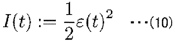
- I (t) denotes an evaluation standard defined by the following formulae (10) and (11).
- a partial differentiation in the second term on the right side of formula (9) is expanded in a manner as shown in formula (12).
- the steepest descent method is repeatedly executed until the evaluation norm defined formulas (10) and (11) becomes sufficiently small.
- the optimum first moment of inertia J ref can be calculated, that is, the first moment of inertia J ref can be calculated so as to cause the first moment of inertia J ref to approach the second moment of inertia J h in the operator's brain.
- a human sensitivity model is set based on the Weber-Fechner's law (I.P. Herman: Physics of the Human Body: Biological and Medical Physics, Biomedical Engineering, Springer-Verlag GmbH & CO. KG (2007)).
- This law is an expanded version of the Weber's law, and is a law derived from a hypothesis that a sense amount F and a stimulus amount R have a correlation expressed by a logarithmic function given as the following formula (13) containing a constant k.
- the target device 10 operated by the operator is the boom of the hydraulic excavator and is given as a first-order lag system expressed by the following formula (14).
- the degree of comfort y (t) is expressed by the following formulae (15) and (16), using Weber-Fechner's law, so that the maximum value of the degree of comfort y (t) is 1.
- r h (t) denotes a target angular velocity of the boom of the hydraulic excavator, the target angular velocity being held in the operator's brain, and is calculated using the following formula (17).
- J h denotes a second moment of inertia of the boom of the hydraulic excavator, the second moment of inertia being held in the operator's brain, and is unknown in this numerical value example.
- e h (t) is a velocity error of the boom of the hydraulic excavator(a difference between the target angular velocity r h and the output angular velocity y ⁇ ), the velocity error being sensed by the operator's brain.
- FIG. 2 is a graph showing a relationship between the difference e h (t) in the operator's brain and the degree of comfort y (t). As shown in FIG. 2 , the degree of comfort y (t) decreases as the difference e h (t) increases. In addition, the rate of decrease of the degree of comfort y (t) increases as E (t) increases.
- Input/output to/from the control unit 30 is subjected to, for example, PID control using K P , K I , and K D as PID parameters, the PID control being expressed by the following formula (19).
- ⁇ (t) in formula (19) denotes a difference between the target angular velocity r ⁇ (t) and the output angular velocity y ⁇ (t), as shown in the following formula (20).
- PID parameter for the control unit 30 existing parameters corresponding to the target device 10 can be used.
- the existing parameters may be fixed constants or variable parameters.
- FIG. 3 shows a simulation result.
- a graph on the top is a graph showing time-dependent changes in the degree of comfort y (t) and the target degree of comfort r (t).
- a continuous line represents the degree of comfort y (t) and a dotted line represents the target degree of comfort r (t).
- a graph in the middle is a graph showing time-dependent changes in the output angular velocity y ⁇ (t) and the target angular velocity r h (t).
- a continuous line represents the output angular velocity y ⁇ (t)
- a dotted line represents the target angular velocity r h (t).
- a graph on the bottom is a graph showing time-dependent changes in the operation input ⁇ h .
- FIG. 4 depicts a state of the first moment of inertia J ref being adjusted.
- a continuous line represents the first moment of inertia J ref
- a dotted line represents the second moment of inertia J h .
- r h (t) (the target angular velocity of the boom of the hydraulic excavator, the target angular velocity being held in the operator's brain) shown in FIG. 3 is a result given by substituting the above set values and the second moment of inertia J h (t) shown in formula (18) into formula (17) and carrying out a calculation.
- the example and numerical value example described above demonstrate that in a case where the boom of the hydraulic excavator is an example of the target device 10 operated by the operator, the degree of comfort in operation of the boom of the hydraulic excavator is improved by performing one-parameter tuning of the first moment of inertia J ref by the control system focusing on controlling the first moment of inertia J ref on the assumption that the degree of comfort of the operator is based on the Weber-Fechner's law.
- the feedback control device 100 has been described for the case where the boom of the hydraulic excavator is the target device.
- the present invention may also be applied to a different device that is at least rotationally operated by the operator.
- one-parameter tuning of the first moment of inertia J ref is performed, with the viscosity coefficient D of formula (1) being set as a fixed value.
- parameter tuning of the viscosity coefficient D as well as the first inertia moment J ref may be performed.
- the transfer function of the target device 10 is not limited to (1/D)/(1+(J/D) ⁇ s). If taking viscosity into consideration is unnecessary, for example, a transfer function not including the viscosity coefficient D may be used. When taking loss into consideration is necessary, a transfer function including a loss term may be used.
- database-driven control by the target angular velocity determining unit 20 may be control using a learning function.
- the target device 10 gradually changes in response behavior so as to make an output response more preferable to the operator.
- the degree of comfort y of the operator can be further improved.
- the first moment of inertia J ref may be adjusted based on the contents of the database 50, sensor input from the target device 10, and the like without using the degree of comfort y.
- a feedback control device includes: a target device that is at least rotationally operated by an operation input by an operator; a first target angular velocity determining unit that determines, based on the operation input, a first target angular velocity that is a target angular velocity of an output angular velocity of the target device, using a first transfer function that is a transfer function of the target device, the first transfer function being defined by a first moment of inertia representing a moment of inertia of the target device; a control unit that determines a control input to the target device, based on a difference between the first target angular velocity and the output angular velocity; a second target angular velocity determining unit that determines, based on the operation input, a second target angular velocity that is the target angular velocity requested by the operator, the target angular velocity corresponding to the operation input; a degree of comfort determining unit that determines a degree of comfort of the operator, based on a difference between the output angular
- the first target angular velocity that is the target angular velocity of the output angular velocity of the target device is determined based on the operation input to the target device.
- the control input to the target device is determined based on the difference between the first target angular velocity and the output angular velocity.
- the degree of comfort of the operator is determined based on the difference between the second target angular velocity that is the target angular velocity requested by the operator, the target angular velocity corresponding to the operation input, and the output angular velocity.
- the first moment of inertia is adjusted in such a way as to reduce the difference between the target degree of comfort and the degree of comfort.
- the first target angular velocity is determined as the first moment of inertia included in the first transfer function is adjusted so that the degree of comfort of the operator is improved, and the control input is determined based on the difference between the first target angular velocity and the output angular velocity.
- the degree of comfort is determined based on the difference between the second target angular velocity requested by the operator, second target angular velocity corresponding to the operation input, and the output angular velocity.
- the degree of comfort determining unit is thus able to determine the degree of comfort so that the degree of comfort takes the highest value when the operator has successfully carried out an operation that makes the target angular velocity of the target device, the target angular velocity being requested by the operator, equal to the actual target angular velocity of the target device. Hence the operator is able to operate the target device comfortably.
- the feedback control device of this embodiment only when the operation input is made, the first target angular velocity is determined, the control input to the target device is determined, and the target device is operated. This prevents a case where the target device starts moving automatically when the operator does not operate the target device, thus ensuring safety.
- the first transfer function has a viscosity coefficient
- the transfer function may be expressed as (1/D)/(1+(J ref /D) ⁇ s).
- the rotational operation of the target device can be accurately feedback-controlled.
- the first target angular velocity determining unit may adjust the first moment of inertia, with the viscosity coefficient D set as a fixed value.
- the first target angular velocity determining unit may further determine the first target angular velocity while adjusting the viscosity coefficient D as a parameter.
- the rotational operation of the target device can be feedback-controlled more accurately.
- the target device may be a boom of a hydraulic excavator.
- the second target angular velocity determining unit has a second transfer function that determines the second target angular velocity corresponding to the operation input, the second transfer function has a second moment of inertia representing a moment of inertia of the target device, the moment of inertia being requested by the operator, and the viscosity coefficient, when the second moment of inertia is J h and the viscosity coefficient is D, the second transfer function is expressed as (1/D)/(1+(J h /D) ⁇ s), and the second moment of inertia J h has an adjusted value of the first moment of inertia J ref .
- the second moment of inertia which is unknown, can be determined using the first moment of inertia.
- the degree of comfort determining unit may set the degree of comfort larger as a difference between the output angular velocity and the second target angular velocity gets smaller.
- a large value of the degree of comfort can be set when the operator has successfully carried out an operation that makes the target angular velocity of the target device, the target angular velocity being requested by the operator, equal to the actual target angular velocity of the target device.
Landscapes
- Engineering & Computer Science (AREA)
- Mining & Mineral Resources (AREA)
- Civil Engineering (AREA)
- General Engineering & Computer Science (AREA)
- Structural Engineering (AREA)
- Physics & Mathematics (AREA)
- General Physics & Mathematics (AREA)
- Automation & Control Theory (AREA)
- Mechanical Engineering (AREA)
- Operation Control Of Excavators (AREA)
- Feedback Control In General (AREA)
Abstract
Description
- The present invention relates to a feedback control device.
- According to a survey by the cabinet office, our country is considered to be a country in which people have a low sense of happiness despite the country's high gross domestic product (GDP). In other words, there is a large gap between "material richness", which is related to the high GDP, and "spiritual richness", which is related to the sense of happiness.
- One of measures for filling such a gap is an idea that an already sophisticated "object" (automobile, welfare support device, etc.) performs an operation in consideration of human sensitivity, thus improving people's spiritual richness.
- While most researches on sensitivity are focused on static fields, such as product evaluation and designing, the inventors of the present invention have proposed a "sensitivity feedback control method" for dynamically controlling sensitivity (for example, Non-Patent Literature 1).
- A conventional sensitivity feedback control method is applied to a cascade control system, which, upon receiving input of a desired degree of comfort, generates a target speed of a control target device by a PID controller. In this process, to deal with the nonlinearity of human sensitivity, a database-driven control method effective for a nonlinear system is used (e.g., Non-Patent Literatures 2 and 3).
- However, according to the conventional "sensitivity feedback control method", a PID gain needs to be adjusted every time the target speed is changed in a person's brain. In an operation system, such as a hydraulic excavator, therefore, the target speed changes in various patterns. Besides, due to the structure of its control system, the hydraulic excavator automatically starts moving even when it is not operated by the person. To prevent this, an additional measure must be taken.
-
- Non-Patent Literature 1: T. Kinoshita and T. Yamamoto, "Design of a Data-Oriented Kansei Feedback Control System", Journal of Robotics, Networking and Artificial Life, Vol.4-No.1, 14/17 (2017)
- Non-Patent Literature 2: T. Yamamoto, K. Takao and T. Yamada, "Design of a Data-Driven PID Controller", IEEE Trans on control systems Technology, Vol.17-No.1, 29/39 (2009)
- Non-Patent Literature 3: Shin Wakitani, Yoshihiro Onishi, Toru Yamamoto, "Design of Nonlinear PID Control System Using FRIT Method", Measurement and Control, Vol. 52 - No. 10, 885/891885/891 (2013)
- An object of the present invention is to provide a feedback control device that allows an operator to comfortably and safely operate a device.
- To achieve the above object, the inventors of the present invention have devoted themselves to their study and have come up with a novel idea about a device that is at least rotationally operated by an operator. The inventors have paid attention to a moment of inertia of a transfer function and conceived an invention according to which the moment of inertia is adjusted as a parameter so as to improve a degree of comfort of the operator.
- A feedback control device according to one aspect of the present disclosure includes: a target device that is at least rotationally operated by an operation input by an operator; a first target angular velocity determining unit that determines, based on the operation input, a first target angular velocity that is a target angular velocity of an output angular velocity of the target device, using a first transfer function that is a transfer function of the target device, the first transfer function being defined by a first moment of inertia representing a moment of inertia of the target device; a control unit that determines a control input to the target device, based on a difference between the first target angular velocity and the output angular velocity; a second target angular velocity determining unit that determines, based on the operation input, a second target angular velocity that is the target angular velocity requested by the operator; a degree of comfort determining unit that determines a degree of comfort of the operator, based on a difference between the output angular velocity and the second target angular velocity; and a database that sequentially accumulates the first target angular velocity, the degree of comfort, and a target degree of comfort, in which the first target angular velocity determining unit adjusts the first moment of inertia in such a way as to reduce a difference between the first target degree of comfort and the degree of comfort, using the first target angular velocity, the degree of comfort, and the target degree of comfort that are accumulated in the database.
-
-
FIG. 1 is a configuration diagram of a feedback control device according to an embodiment. -
FIG. 2 depicts a relationship between a degree of comfort and an output error in the feedback control device according to the embodiment. -
FIG. 3 depicts a result of simulation of time-dependent changes in a degree of comfort, an output angular velocity, and an operation input, the time-dependent changes occurring in feedback control using the feedback control device according to the embodiment. -
FIG. 4 depicts a state of a moment of inertia being adjusted in feedback control using the feedback control device according to the embodiment. - A feedback control device according to an embodiment of the present invention will now be described with reference to the drawings. The scope of the present invention is not limited to the following embodiment, and may be changed within the scope of the technical idea of the present invention whenever necessary.
-
FIG. 1 is a configuration diagram of afeedback control device 100 according to an embodiment. As shown inFIG. 1 , thefeedback control device 100 includes atarget device 10, a target angular velocity determining unit 20 (first target angular velocity determining unit), acontrol unit 30, a degree ofcomfort determining unit 40, and adatabase 50. Thefeedback control device 100 further includes an in-brain target angular velocity determining unit 70 (second target angular velocity determining unit), anoperation mechanism 60,subtractors comfort setting unit 90. - The
target device 10 is a device that is at least rotationally operated by an operation input τh by an operator. Thetarget device 10 is, for example, a rotary drive unit of an automobile, a construction machine, or the like. The rotary drive unit is, for example, a boom of a hydraulic excavator. Thetarget device 10 operates at an output angular velocity yω corresponding to a control input τ inputted from thecontrol unit 30. Thetarget device 10 inputs the output angular velocity yω to thesubtractor 82 and feeds back the output angular velocity yω to thesubtractor 81 as well. - Based on the operator's operation input τh to the
target device 10, the target angularvelocity determining unit 20 determines a target angular velocity rω (first target angular velocity) of the output angular velocity yω of thetarget device 10, using a first transfer function that is a transfer function of thetarget device 10. The first transfer function has a first moment of inertia representing a moment of inertia of thetarget device 10. - Specifically, the target angular
velocity determining unit 20 adjusts the first moment of inertia as a parameter in such a way as to reduce a difference between a target degree of comfort r and a degree of comfort y, using the target degree of comfort r, the degree of comfort y, and the target angular velocity rω that are stored in thedatabase 50. The target angularvelocity determining unit 20 inputs the operation input τh to the first transfer function with the first moment of inertia being adjusted, thereby determining the target angular velocity rω. - The operator's operation of the
target device 10 is inputted to theoperation mechanism 60. Specifically, theoperation mechanism 60 includes an operation lever to which the operator's operation for driving the rotation drive unit is applied. Theoperation mechanism 60 inputs the inputted operation input τh to the target angularvelocity determining unit 20 and to the in-brain target angularvelocity determining unit 70. - The
subtractor 81 subtracts the output angular velocity yω from the target angular velocity rω to calculate a difference between them, and inputs the difference to thecontrol unit 30. - The
control unit 30 determines the control input τ to thetarget device 10 by, for example, PID control, based on the difference between the target angular velocity rω and the output angular velocity yω. Specifically, thecontrol unit 30 determines the control input τ by PID control in such a way as to reduce the difference inputted from thesubtractor 81 to thecontrol unit 30. - The
subtractor 82 subtracts the output angular velocity yω from the target angular velocity rh to calculate a difference eh (velocity deviation), and inputs the difference eh to the degree ofcomfort determining unit 40. - The degree of
comfort determining unit 40 determines the degree of comfort y, based on the difference eh. The degree ofcomfort determining unit 40 inputs the degree of comfort y to thedatabase 50 and thesubtractor 83, and outputs the degree of comfort y to an external device as well. - The
subtractor 83 calculates a difference between the target degree of comfort r and the degree of comfort y, and inputs the difference to the target angularvelocity determining unit 20. - The
database 50 sequentially accumulates the target angular velocity rω, the degree of comfort y, and the target degree of comfort r of the degree of comfort y. - The target degree of
comfort setting unit 90 sets the target degree of comfort r, and inputs the set target degree of comfort r to thedatabase 50 and to thesubtractor 83. For example, a preset value is adopted as the target degree of comfort r. - In the
feedback control device 100 of this embodiment, respective functions of the target angularvelocity determining unit 20, thecontrol unit 30, the degree ofcomfort determining unit 40, the in-brain target angularvelocity determining unit 70, and the target degree ofcomfort setting unit 90 are implemented by a computer's executing a program. The computer includes main hardware components, such as a processor that operates according to a program and a memory that stores data necessary for executing the program. - Furthermore, in the
feedback control device 100 of this embodiment, thedatabase 50 includes a computer-readable recording medium, such as a ROM, an optical disk, and a hard disk drive. - One of the features of the
feedback control device 100 of this embodiment is that the target angularvelocity determining unit 20 determines the target angular velocity rω while adjusting the first moment of inertia as a parameter in such a way as to reduce the difference between the target degree of comfort r and the degree of comfort y, using the target degree of comfort r, the degree of comfort y, and the target angular velocity rω that are stored in thedatabase 50. A method of adjusting the first moment of inertia will be described in detail in examples that will be described later. - The first transfer function is expressed as, for example, (1/D)/(1+(J/D)·s), where J denotes the first moment of inertia and D denotes a viscosity coefficient. In this case, 1/D denotes a system gain. For example, a steady angular velocity that results when the boom of the hydraulic excavator is operated by full-range lever shifting can be measured easily. Based on this fact, the target angular
velocity determining unit 20 may determine the target angular velocity rω, with the viscosity coefficient D given as a known fixed value. Alternatively, the target angularvelocity determining unit 20 may determine the target angular velocity rω while adjusting the viscosity coefficient D as well as the first moment of inertia J as a parameter. - In the present invention, the first moment of inertia of the
target device 10 is referred to as "J ", and the first moment of inertia adjusted as a parameter by the target angularvelocity determining unit 20 is referred to as "Jref". - The degree of
comfort determining unit 40, for example, may acquire a biological reaction, such as heartbeat, of the operator by a sensor or the like, and determine the degree of comfort y of the operator, based on the biological reaction. Alternatively, the degree ofcomfort determining unit 40 may determine the degree of comfort y preferable to the operator, using a degree of comfort that the operator has entered by himself or herself using an input device, such as a touch panel. - Based on the operation input τh requested by the operator, the in-brain target angular
velocity determining unit 70 determines a target angular velocity rh (second target angular velocity) that is a target angular velocity corresponding to the operation input τh. The target angular velocity rh is, for example, the target angular velocity (desired angular velocity) that corresponds to operation input τh in the operator's brain, the operation input τh being made by the operator himself or herself. The difference eh between the target angular velocity rh and the output angular velocity yω is a factor that determines the degree of comfort y of the operator. For example, when the difference eh between the target angular velocity rh and the output angular velocity yω is 0, the degree of comfort y takes a highest value. The difference eh being 0 means that the operator has actually been able to operate thetarget device 10 so as to obtain the output angular velocity yω that matches the target angular velocity rh. In a practical operation of thefeedback control device 100, the values of both target angular velocity rh and difference eh are unknown. The in-brain target angularvelocity determining unit 70 inputs the operation input τh to a second transfer function to calculate the target angular velocity rh. - The second transfer function is expressed, for example, as (1/D)/(1+(Jh/D)·s), where Jh denotes a second moment of inertia representing a moment of inertia of the
target device 10 that is requested by the operator and D denotes the viscosity coefficient. The value of the second moment of inertia Jh is unknown. - The above-described
feedback control device 100 of this embodiment includes the target angularvelocity determining unit 20 that determines the target angular velocity rω of the output angular velocity yω of thetarget device 10, based on the operation input τh to thetarget device 10, and thecontrol unit 30 that determines the control input τ to thetarget device 10, based on the difference between the target angular velocity rω and the output angular velocity yω. Thefeedback control device 100 further includes the in-brain target angularvelocity determining unit 70 that determines the target angular velocity rh that is the target angular velocity requested by the operator, based on the operation input τh, and the degree ofcomfort determining unit 40 that determines the degree of comfort y of the operator, based on the difference eh between the output angular velocity yω and the target angular velocity rh. The target angularvelocity determining unit 20 determines the target angular velocity rω while adjusting the first moment of inertia Jref as a parameter in such a way as to reduce the difference between the target degree of comfort r and the degree of comfort y. - The degree of comfort is determined based on the difference eh between the target angular velocity rh and the output angular velocity yω. The degree of
comfort determining unit 40 is thus able to determine the degree of comfort so that the degree of comfort takes the highest value when the operator has successfully carried out an operation that makes the target angular velocity of the target device, the target angular velocity being requested by the operator, equal to the actual target angular velocity of the target device. Hence the operator is able to operate thetarget device 10 comfortably. - According to the
feedback control device 100 of this embodiment, only when the operation input τh is inputted by the operator to thetarget device 10, the target angular velocity rω is determined, the control input τ to thetarget device 10 is determined, and thetarget device 10 is operated. This prevents a case where thetarget device 10 starts moving automatically when the operator does not operate thetarget device 10, thus ensuring safety. - As described above, according to this embodiment, the
feedback control device 100 that allows the operator to comfortably and safely operate a device is provided. - According to the
feedback control device 100 of this embodiment, when the first moment of inertia is denoted by Jref and the viscosity coefficient is denoted by D, the first transfer function is expressed as (1/D)/(1+(Jref/D)·s). - Based on this first transfer function, the
feedback control device 100 can accurately feedback-control the rotation movement of thetarget device 10. In this case, the target angularvelocity determining unit 20 may determine the target angular velocity rω, with the viscosity coefficient D given as a known fixed value. - This reduces parameters to be adjusted to the first moment of inertia Jref alone, thus allowing one-parameter tuning. The target angular
velocity determining unit 20 may determine the target angular velocity rω while adjusting the viscosity coefficient D as well as the first moment of inertia Jref as a parameter. In this case, thefeedback control device 100 can feedback-control the rotation movement of thetarget device 10 more accurately while taking into consideration the temperature dependency of the viscosity coefficient D or the like. - In the
feedback control device 100 of this embodiment, thetarget device 10 may be a boom of a hydraulic excavator. - In this case, the operator is allowed to operate the boom of the hydraulic excavator comfortably and safely.
- In the
feedback control device 100 of this embodiment, the in-brain target angularvelocity determining unit 70 has the second transfer function that determines the target angular velocity rh corresponding to the operation input τh. The second transfer function is expressed as (1/D)/(1+(Jh/D)·s), where Jh denotes the second moment of inertia and D denotes the viscosity coefficient. The in-brain target angularvelocity determining unit 70 sets the second moment of inertia Jh, using the adjusted value of the first moment of inertia Jref. - In this case, the second moment of inertia Jh, which is unknown, can be determined using the first moment of inertia Jref.
- An example (simulation example) of the
feedback control device 100 shown inFIG. 1 will hereinafter be described. In this example, thetarget device 10 is the boom of the hydraulic excavator, and the degree of comfort y in boom operation by the operator can be measured. The "target degree of comfort r" is given as the target value of the degree of comfort y, and the output angular velocity yω of the boom of the hydraulic excavator is controlled so that the degree of comfort y meets the target value, i.e., "target degree of comfort r". - An object of this example is to improve a degree of comfort y (t) (t denotes time). It is not easy to directly set a proper target angular velocity rω (t) of the target device 10 (the boom of the hydraulic excavator) at each point of time. The proper target angular velocity rω (t) is thus automatically generated at each point of time from a relationship between the operation input (lever input torque in this example) τh (t) and the first moment of inertia Jref, as indicated by the following formula (1).
- [Mathematical formula 1]

- In formula (1), Jref denotes the first moment of inertia which is targeted at by a closed-loop transfer function including the boom of the hydraulic excavator, and D denotes the viscosity resistance. In formula (1), 1/D denotes the system gain. Because the steady angular velocity that results when the boom of the hydraulic excavator is operated by full-range lever shifting can be measured easily, the viscosity coefficient D is treated as a known fixed value in this example.
- In this example, the first moment of inertia Jref is adjusted based on a database-driven approach, which will be described later, so as to improve the degree of comfort y. Now the second moment of inertia in the operator's brain, the second moment of inertia being requested by the operator, is defined as Jh. When the first moment of inertia Jref becomes equal to the second moment of inertia Jh, the moment of inertia of the actual control system matches the moment of inertia in the brain. A state in which the first moment of inertia Jref is equal to the second moment of inertia Jh is, therefore, the most comfortable state. In other words, the degree of comfort y takes the value indicating the most comfortable state when the operator has successfully carried out the same operation as the operation that achieves a target response velocity of the hydraulic excavator, the target response velocity being in the operator's brain as a requested response velocity.
- In this example, the degree of comfort y (t) to be controlled is a discrete time nonlinear system expressed by the following formula (2).
- [Mathematical formula 2]

- In formula (2), y (t) denotes a system output. f () denotes a nonlinear function. φ (t-1) denotes an information vector representing a state of the system before time t. The information vector φ (t-1) is defined by the following formula (3).
- [Mathematical formula 3]

- In formula (3), rω (t) (the target angular velocity of the target device 10) denotes a system input in control of the degree of comfort y (t). ny denotes the order of a system output. nw denotes the order of a system input. In database-driven control, each piece of operational data is accumulated in the database 50 (see
FIG. 1 ) in the form of data expressed by formula (3). In addition, an information vector φ (t) representing the current state of the system is referred to as a request point (query). - Hereinafter, adjustment of the first moment of inertia Jref by database-driven control carried out by the target angular
velocity determining unit 20 using the data accumulated in thedatabase 50 will be described in detail. - In database-driven control, when past accumulated data is not present, the first moment of inertia Jref cannot in principle be adjusted. In this case, therefore, input/output data is acquired using the initial first moment of inertia Jref, and an initial database (a part of the database 50) made up of information vectors φ expressed by the following formula (4) is created.
- [Mathematical formula 4]

- In formula (4), j = 1, 2, .., N (0), and -φ (j) is given by the following formula (5).
- [Mathematical formula 5]

- N (0) denotes the number of initial data (the number of information vectors making up the initial database). Because the first moment of inertia Jref estimated in the initial database is fixed, Jref (1) = Jref (2)= ... =Jref (N (0)) holds.
- The distance between the request point -φ (t) and the information vector -φ (j) stored in the database is determined as a weighted L1 norm expressed by the following formula (6).
- [Mathematical formula 6]

- In formula (6), j= 1, 2, ..., N (t), and N (t) denotes the number of data (information vectors) stored in the database at time t. -φl (j) denotes the l-th element of the j-th information vector. Similarly, -φl (t) represents the l-th element of the request point at time t. Further, max-φl (m) denotes the largest element among the l-th elements of all information vectors (-φ (j): j=1, 2, ..., N (t)) present in the database, and min-φl (m) denotes the smallest element among the l-th elements.
- In this example, k information vectors are selected in the order in which the distance d obtained by formula (6) is smaller, and a set of selected data is defined as a neighborhood.
- Next, for the neighborhood defined in the above manner, a local controller is configured by a linearly weighted average (LWA) method expressed by the following formula (7).
- [Mathematical formula 7]

- In formula (7), wi denotes a weight for Jref (i) included in the selected i-th information vector and is given by the following formula (8).
- [Mathematical formula 8]

- Through the above procedure, a first moment of inertia Jrefold (t) at each time t can be calculated. Now, to allow proper adjustment of the first moment of inertia Jref by the database-driven approach, letting the
database 50 learn improved data is necessary. In this example, Jref in each data set in thedatabase 50 is updated by a steepest descent method. - In this example, the first moment of inertia Jref is adjusted, using the following equation (9) representing the steepest descent method.
- [Mathematical formula 9]

- In formula (9), η denotes a learning coefficient, and I (t) denotes an evaluation standard defined by the following formulae (10) and (11).
- [Mathematical formula 10]
- [Mathematical formula 11]

- A partial differentiation in the second term on the right side of formula (9) is expanded in a manner as shown in formula (12).
- [Mathematical formula 12]

- The steepest descent method is repeatedly executed until the evaluation norm defined formulas (10) and (11) becomes sufficiently small. By this approach, the optimum first moment of inertia Jref can be calculated, that is, the first moment of inertia Jref can be calculated so as to cause the first moment of inertia Jref to approach the second moment of inertia Jh in the operator's brain.
- In this example, a human sensitivity model is set based on the Weber-Fechner's law (I.P. Herman: Physics of the Human Body: Biological and Medical Physics, Biomedical Engineering, Springer-Verlag GmbH & CO. KG (2007)). This law is an expanded version of the Weber's law, and is a law derived from a hypothesis that a sense amount F and a stimulus amount R have a correlation expressed by a logarithmic function given as the following formula (13) containing a constant k.
- [Mathematical formula 13]

- The Weber-Fechner's law corresponds to an intuitive fact that the intensity of sensation changes rapidly in response to an initial stimulus but a rate of increase of sensation drops gradually as the intensity of stimulus increases (Eitaro Masuyama: "Sensory tests viewed from the standpoint of psychology", Sensory tests and psychology, Vol. 22 - No. 3, 107/114 (1986)). For example, in an experiment in which a person lifts a 100 g weight, the way the person feels the weight differs greatly between a case of lifting the weight from a state of already holding a 1 kg weight and a case of lighting the weight in a state of holding nothing. In this manner, it is confirmed that the way the person senses the weight gets duller as the weight increases. Specific formulae involved in a human sensitivity model will be described in the following numerical value example.
- A numerical value example of feedback control according to the above-described example will hereinafter be described.
- It is assumed in the
feedback control device 100 shown inFIG. 1 that thetarget device 10 operated by the operator is the boom of the hydraulic excavator and is given as a first-order lag system expressed by the following formula (14). - [Mathematical formula 14]

- Meanwhile, the degree of comfort y (t) is expressed by the following formulae (15) and (16), using Weber-Fechner's law, so that the maximum value of the degree of comfort y (t) is 1.
- [Mathematical formula 15]

- [Mathematical formula 16]

- In formulae (15) and (16), rh (t) denotes a target angular velocity of the boom of the hydraulic excavator, the target angular velocity being held in the operator's brain, and is calculated using the following formula (17).
- [Mathematical formula 17]

- In formula (17), Jh denotes a second moment of inertia of the boom of the hydraulic excavator, the second moment of inertia being held in the operator's brain, and is unknown in this numerical value example. eh (t) is a velocity error of the boom of the hydraulic excavator(a difference between the target angular velocity rh and the output angular velocity yω), the velocity error being sensed by the operator's brain.
- It follows from formula (15) that the difference eh (t) in the operator's brain is 0, the degree of comfort y (t) is 1, which is the maximum degree of comfort. It should be noted that E (t) is a variable that varies with respect to the degree of comfort y (t), and takes different values for different operators. E (t) for each operator may be determined based on the biological response of a biological sensor, or may be determined based on the degree of comfort y inputted by the operator.
FIG. 2 is a graph showing a relationship between the difference eh (t) in the operator's brain and the degree of comfort y (t). As shown inFIG. 2 , the degree of comfort y (t) decreases as the difference eh (t) increases. In addition, the rate of decrease of the degree of comfort y (t) increases as E (t) increases. - It should be noted that setting parameters in numerical expressions shown below are given values such that r (t)=1.0 (fixed to the
maximum value 1 of the degree of comfort y (t)), η=0.8, E (t)=1, and D=1. - In this numerical value example, it is assumed that the boom of the hydraulic excavator is operated to move vertically. In such a vertical movement, due to gravity, the velocity of the boom in descending movement gets higher than the velocity of the boom in ascending movement. It is therefore assumed that the operator puts the above fact in the operator's brain as a pre-conceived image. A case is assumed where the second moment of inertia Jh (t) changes depending on a given operation input (lever input torque) τn (t), the case being expressed as the following formula (18). Under this assumption, the followability of the first moment of inertia Jref (t) to the second moment of inertia Jh (t) has been checked, the first moment of inertia Jref (t) being obtained by the adjustment method described in the example.
- [Mathematical formula 18]

- Input/output to/from the
control unit 30 is subjected to, for example, PID control using KP, KI, and KD as PID parameters, the PID control being expressed by the following formula (19). - [Mathematical formula 19]

- ε (t) in formula (19) denotes a difference between the target angular velocity rω (t) and the output angular velocity yω (t), as shown in the following formula (20).
- [Mathematical formula 20]

- As the PID parameter for the
control unit 30, existing parameters corresponding to thetarget device 10 can be used. The existing parameters may be fixed constants or variable parameters. In this numerical value example, PID parameters Kp=10, KI=0.5, and KD=0 are used. - With the above setting, a simulation of time-dependent changes in the degree of comfort y (t), the output angular velocity yω (t), and the operation input (lever input) τh (t) has been executed as the first moment of inertia Jref (t) is adjusted by the database-driven control.
FIG. 3 shows a simulation result. InFIG. 3 , a graph on the top is a graph showing time-dependent changes in the degree of comfort y (t) and the target degree of comfort r (t). In this graph on the top, a continuous line represents the degree of comfort y (t) and a dotted line represents the target degree of comfort r (t). InFIG. 3 , a graph in the middle is a graph showing time-dependent changes in the output angular velocity yω (t) and the target angular velocity rh (t). In this graph in the middle, a continuous line represents the output angular velocity yω (t) and a dotted line represents the target angular velocity rh (t). InFIG. 3 , a graph on the bottom is a graph showing time-dependent changes in the operation input τh.FIG. 4 depicts a state of the first moment of inertia Jref being adjusted. InFIG. 4 , a continuous line represents the first moment of inertia Jref, and a dotted line represents the second moment of inertia Jh. It should be noted that rh (t) (the target angular velocity of the boom of the hydraulic excavator, the target angular velocity being held in the operator's brain) shown inFIG. 3 is a result given by substituting the above set values and the second moment of inertia Jh (t) shown in formula (18) into formula (17) and carrying out a calculation. - It can be confirmed from
FIG. 3 that the degree of comfort (system output) y (t) follows the target degree of comfort r (t) (= 1). This can be confirmed also from a fact that the output angular velocity yω (t) follows the target angular velocity rh (t). In this situation, the second moment of inertia Jh (t) is changed by the operation input (lever input) τh (t). It can be understood fromFIG. 4 , however, that the first moment of inertia Jref (t) is properly estimated by database-driven control of the example so that the first moment of inertia Jref (t) follows the second moment of inertia Jh (t). This implies that applying database-driven control of the example enables estimation of the second moment of inertia Jh given by the operator. - The example and numerical value example described above demonstrate that in a case where the boom of the hydraulic excavator is an example of the
target device 10 operated by the operator, the degree of comfort in operation of the boom of the hydraulic excavator is improved by performing one-parameter tuning of the first moment of inertia Jref by the control system focusing on controlling the first moment of inertia Jref on the assumption that the degree of comfort of the operator is based on the Weber-Fechner's law. - The embodiment (including the example) of the present invention has been described above. The present invention is not limited to the embodiment, and may be modified into various forms within the scope of the invention. In other words, the description of the embodiment is merely exemplary in nature, and is not intended to limit the present invention, its applications, or its use.
- For example, in the above embodiment, the
feedback control device 100 has been described for the case where the boom of the hydraulic excavator is the target device. The present invention, however, may also be applied to a different device that is at least rotationally operated by the operator. - In the above embodiment, one-parameter tuning of the first moment of inertia Jref is performed, with the viscosity coefficient D of formula (1) being set as a fixed value. Instead of performing this tuning, however, parameter tuning of the viscosity coefficient D as well as the first inertia moment Jref may be performed. The transfer function of the
target device 10 is not limited to (1/D)/(1+(J/D)·s). If taking viscosity into consideration is unnecessary, for example, a transfer function not including the viscosity coefficient D may be used. When taking loss into consideration is necessary, a transfer function including a loss term may be used. - In the
feedback control device 100, database-driven control by the target angularvelocity determining unit 20 may be control using a learning function. In this case, as an operation time of thetarget device 10 operated by the operator gets longer, thetarget device 10 gradually changes in response behavior so as to make an output response more preferable to the operator. As a result, the degree of comfort y of the operator can be further improved. In particular, in a case where thedatabase 50 makes progress in learning and is customized for individual operators, the first moment of inertia Jref may be adjusted based on the contents of thedatabase 50, sensor input from thetarget device 10, and the like without using the degree of comfort y. - A feedback control device according to the embodiment includes: a target device that is at least rotationally operated by an operation input by an operator; a first target angular velocity determining unit that determines, based on the operation input, a first target angular velocity that is a target angular velocity of an output angular velocity of the target device, using a first transfer function that is a transfer function of the target device, the first transfer function being defined by a first moment of inertia representing a moment of inertia of the target device; a control unit that determines a control input to the target device, based on a difference between the first target angular velocity and the output angular velocity; a second target angular velocity determining unit that determines, based on the operation input, a second target angular velocity that is the target angular velocity requested by the operator, the target angular velocity corresponding to the operation input; a degree of comfort determining unit that determines a degree of comfort of the operator, based on a difference between the output angular velocity and the second target angular velocity; and a database that sequentially accumulates the first target angular velocity, the degree of comfort, and a target degree of comfort, in which the first target angular velocity determining unit adjusts the first moment of inertia in such a way as to reduce a difference between the first target degree of comfort and the degree of comfort, using the first target angular velocity, the degree of comfort, and the target degree of comfort that are accumulated in the database.
- According to this configuration, the first target angular velocity that is the target angular velocity of the output angular velocity of the target device is determined based on the operation input to the target device. The control input to the target device is determined based on the difference between the first target angular velocity and the output angular velocity. The degree of comfort of the operator is determined based on the difference between the second target angular velocity that is the target angular velocity requested by the operator, the target angular velocity corresponding to the operation input, and the output angular velocity. The first moment of inertia is adjusted in such a way as to reduce the difference between the target degree of comfort and the degree of comfort. In this manner, the first target angular velocity is determined as the first moment of inertia included in the first transfer function is adjusted so that the degree of comfort of the operator is improved, and the control input is determined based on the difference between the first target angular velocity and the output angular velocity.
- The degree of comfort is determined based on the difference between the second target angular velocity requested by the operator, second target angular velocity corresponding to the operation input, and the output angular velocity. The degree of comfort determining unit is thus able to determine the degree of comfort so that the degree of comfort takes the highest value when the operator has successfully carried out an operation that makes the target angular velocity of the target device, the target angular velocity being requested by the operator, equal to the actual target angular velocity of the target device. Hence the operator is able to operate the target device comfortably.
- According to the feedback control device of this embodiment, only when the operation input is made, the first target angular velocity is determined, the control input to the target device is determined, and the target device is operated. This prevents a case where the target device starts moving automatically when the operator does not operate the target device, thus ensuring safety.
- In the above feedback control device, the first transfer function has a viscosity coefficient, and when the first moment of inertia is Jref and the viscosity coefficient is D, the transfer function may be expressed as (1/D)/(1+(Jref/D)·s).
- According to this configuration, the rotational operation of the target device can be accurately feedback-controlled.
- In the above feedback control device, the first target angular velocity determining unit may adjust the first moment of inertia, with the viscosity coefficient D set as a fixed value.
- This reduces parameters to be adjusted to the first moment of inertia alone, thus allowing one-parameter tuning.
- In the above feedback control device, the first target angular velocity determining unit may further determine the first target angular velocity while adjusting the viscosity coefficient D as a parameter.
- According to this configuration, the rotational operation of the target device can be feedback-controlled more accurately.
- In the above feedback control device, the target device may be a boom of a hydraulic excavator.
- In this configuration, the operator is allowed to operate the boom of the hydraulic excavator comfortably and safely.
- According to the above feedback control device, the second target angular velocity determining unit has a second transfer function that determines the second target angular velocity corresponding to the operation input, the second transfer function has a second moment of inertia representing a moment of inertia of the target device, the moment of inertia being requested by the operator, and the viscosity coefficient, when the second moment of inertia is Jh and the viscosity coefficient is D, the second transfer function is expressed as (1/D)/(1+(Jh/D)·s), and the second moment of inertia Jh has an adjusted value of the first moment of inertia Jref.
- According to this configuration, the second moment of inertia, which is unknown, can be determined using the first moment of inertia.
- In the above feedback control device, the degree of comfort determining unit may set the degree of comfort larger as a difference between the output angular velocity and the second target angular velocity gets smaller.
- According to this configuration, a large value of the degree of comfort can be set when the operator has successfully carried out an operation that makes the target angular velocity of the target device, the target angular velocity being requested by the operator, equal to the actual target angular velocity of the target device.
Claims (7)
- A feedback control device comprising:a target device that is at least rotationally operated by an operation input by an operator;a first target angular velocity determining unit that determines, based on the operation input, a first target angular velocity that is a target angular velocity of an output angular velocity of the target device, using a first transfer function that is a transfer function of the target device, the first transfer function being defined by a first moment of inertia representing a moment of inertia of the target device;a control unit that determines a control input to the target device, based on a difference between the first target angular velocity and the output angular velocity;a second target angular velocity determining unit that determines, based on the operation input, a second target angular velocity that is the target angular velocity requested by the operator, the target angular velocity corresponding to the operation input;a degree of comfort determining unit that determines a degree of comfort of the operator, based on a difference between the output angular velocity and the second target angular velocity; anda database that sequentially accumulates the first target angular velocity, the degree of comfort, and a target degree of comfort,wherein the first target angular velocity determining unit adjusts the first moment of inertia in such a way as to reduce a difference between the target degree of comfort and the degree of comfort, using the first target angular velocity, the degree of comfort, and the target degree of comfort that are accumulated in the database.
- The feedback control device according to claim 1, whereinthe first transfer function is further defined by a viscosity coefficient, andwhen the first moment of inertia is Jref and the viscosity coefficient is D, the first transfer function is expressed as (1/D)/(1+(Jref/D)·s).
- The feedback control device according to claim 2, wherein the first target angular velocity determining unit adjusts the first moment of inertia, with the viscosity coefficient D set as a fixed value.
- The feedback control device according to claim 2, wherein the first target angular velocity determining unit further determines the first target angular velocity while adjusting the viscosity coefficient D as a parameter.
- The feedback control device according to any one of claims 1 to 4, wherein the target device is a boom of a hydraulic excavator.
- The feedback control device according to claim 2, whereinthe second target angular velocity determining unit has a second transfer function that determines the second target angular velocity corresponding to the operation input,the second transfer function is defined by a second moment of inertia representing a moment of inertia of the target device, the moment of inertia being requested by the operator, and by the viscosity coefficient,when the second moment of inertia is Jh and the viscosity coefficient is D, the second transfer function is expressed as (1/D)/(1+(Jh/D)·s), andthe second moment of inertia Jh has an adjusted value of the first moment of inertia Jref.
- The feedback control device according to any one of claims 1 to 6, wherein the degree of comfort determining unit sets the degree of comfort larger as a difference between the output angular velocity and the second target angular velocity gets smaller.
Applications Claiming Priority (2)
| Application Number | Priority Date | Filing Date | Title |
|---|---|---|---|
| JP2019220130A JP7257943B2 (en) | 2019-12-05 | 2019-12-05 | feedback controller |
| PCT/JP2020/042927 WO2021111874A1 (en) | 2019-12-05 | 2020-11-18 | Feedback control device |
Publications (3)
| Publication Number | Publication Date |
|---|---|
| EP4047140A1 true EP4047140A1 (en) | 2022-08-24 |
| EP4047140A4 EP4047140A4 (en) | 2023-01-11 |
| EP4047140B1 EP4047140B1 (en) | 2023-10-25 |
Family
ID=76220628
Family Applications (1)
| Application Number | Title | Priority Date | Filing Date |
|---|---|---|---|
| EP20897406.3A Active EP4047140B1 (en) | 2019-12-05 | 2020-11-18 | Feedback control device |
Country Status (5)
| Country | Link |
|---|---|
| US (1) | US12209386B2 (en) |
| EP (1) | EP4047140B1 (en) |
| JP (1) | JP7257943B2 (en) |
| CN (1) | CN114730162B (en) |
| WO (1) | WO2021111874A1 (en) |
Families Citing this family (2)
| Publication number | Priority date | Publication date | Assignee | Title |
|---|---|---|---|---|
| US11782402B2 (en) * | 2021-07-02 | 2023-10-10 | Mitsubishi Electric Research Laboratories, Inc. | Device for controlling a system with polynomial dynamics |
| US12366834B2 (en) * | 2022-07-05 | 2025-07-22 | Mitsubishi Electric Research Laboratories, Inc. | Device for controlling a system with polynomial dynamics |
Family Cites Families (17)
| Publication number | Priority date | Publication date | Assignee | Title |
|---|---|---|---|---|
| CA2243266C (en) * | 1996-12-12 | 2003-10-14 | Shin Caterpillar Mitsubishi Ltd. | Control apparatus for a construction machine |
| EP2050653B1 (en) * | 2007-10-19 | 2010-09-22 | Honda Motor Co., Ltd. | Steering system |
| JP5640511B2 (en) * | 2010-07-12 | 2014-12-17 | マツダ株式会社 | Driving skill training device for vehicles |
| US8872640B2 (en) | 2011-07-05 | 2014-10-28 | Saudi Arabian Oil Company | Systems, computer medium and computer-implemented methods for monitoring health and ergonomic status of drivers of vehicles |
| US9181682B2 (en) | 2013-04-23 | 2015-11-10 | Caterpillar Inc. | Aggressive and stable speed control |
| CN106574797B (en) * | 2014-09-01 | 2019-08-06 | 三菱电机株式会社 | Control device of air conditioning system and control method of air conditioning system |
| CN105717960B (en) * | 2014-12-04 | 2018-01-19 | 台达电子工业股份有限公司 | environmental comfort control system and control method thereof |
| CN104656556B (en) * | 2015-01-23 | 2017-10-13 | 清能德创电气技术(北京)有限公司 | A kind of ratio of inertias adjusting method adaptive based on reference model |
| US10254726B2 (en) * | 2015-01-30 | 2019-04-09 | Schneider Electric USA, Inc. | Interior comfort HVAC user-feedback control system and apparatus |
| JP2016216909A (en) * | 2015-05-14 | 2016-12-22 | 住友重機械工業株式会社 | Excavator |
| JP6590411B2 (en) | 2015-10-16 | 2019-10-16 | 国立大学法人広島大学 | Kansei evaluation method |
| JP6833195B2 (en) * | 2016-08-30 | 2021-02-24 | 国立大学法人広島大学 | Data-oriented feedback control device and data-oriented feedback control method |
| CN109476310B (en) * | 2016-12-30 | 2021-11-12 | 同济大学 | Automatic driving vehicle speed control method based on comfort level |
| CN110139793B (en) * | 2017-02-02 | 2021-05-07 | 日本精工株式会社 | Electric power steering apparatus |
| JP6531876B2 (en) * | 2017-02-09 | 2019-06-19 | 日本精工株式会社 | Electric power steering device |
| EP3495244B1 (en) * | 2017-10-24 | 2020-12-30 | NSK Ltd. | Electric power steering apparatus |
| EP3808639B1 (en) * | 2018-12-14 | 2022-05-04 | Nsk Ltd. | Electric power steering device |
-
2019
- 2019-12-05 JP JP2019220130A patent/JP7257943B2/en active Active
-
2020
- 2020-11-18 US US17/779,242 patent/US12209386B2/en active Active
- 2020-11-18 CN CN202080082965.3A patent/CN114730162B/en active Active
- 2020-11-18 WO PCT/JP2020/042927 patent/WO2021111874A1/en not_active Ceased
- 2020-11-18 EP EP20897406.3A patent/EP4047140B1/en active Active
Also Published As
| Publication number | Publication date |
|---|---|
| EP4047140A4 (en) | 2023-01-11 |
| JP7257943B2 (en) | 2023-04-14 |
| CN114730162A (en) | 2022-07-08 |
| CN114730162B (en) | 2024-12-06 |
| WO2021111874A1 (en) | 2021-06-10 |
| US20220403621A1 (en) | 2022-12-22 |
| EP4047140B1 (en) | 2023-10-25 |
| JP2021089624A (en) | 2021-06-10 |
| US12209386B2 (en) | 2025-01-28 |
Similar Documents
| Publication | Publication Date | Title |
|---|---|---|
| Bhanpuri et al. | Predicting and correcting ataxia using a model of cerebellar function | |
| Narayanan et al. | Event-sampled output feedback control of robot manipulators using neural networks | |
| Lee et al. | A closed-loop artificial pancreas based on model predictive control: Human-friendly identification and automatic meal disturbance rejection | |
| JP7019127B2 (en) | Insulin assessment based on reinforcement learning | |
| EP4047140B1 (en) | Feedback control device | |
| Wong et al. | Is natural variability in gait sufficient to initiate spontaneous energy optimization in human walking? | |
| Gaweda et al. | Individualization of pharmacological anemia management using reinforcement learning | |
| CN101903882A (en) | Substance monitoring and control in the human or animal body | |
| Rougier et al. | How proprioceptive impairments affect quiet standing in patients with multiple sclerosis | |
| Chen et al. | Design and analysis of integrated predictive iterative learning control for batch process based on two-dimensional system theory | |
| Jin et al. | Disturbance rejection model predictive control of lower limb rehabilitation exoskeleton | |
| JP6833195B2 (en) | Data-oriented feedback control device and data-oriented feedback control method | |
| Kovacs et al. | Virtual stick balancing: sensorimotor uncertainties related to angular displacement and velocity | |
| Amilo | A quantum-inspired neural fuzzy sliding mode control framework for fractional-order modeling of intraocular pressure regulation and optic nerve damage in glaucoma | |
| Khani et al. | Type 3 Fuzzy Predictive Control of the Insulin-Glucose System in Type 1 Diabetes. | |
| Tietäväinen et al. | Bayesian inference of physiologically meaningful parameters from body sway measurements | |
| Bolotnik et al. | Periodic locomotion of a two‐body crawling system along a straight line on a rough inclined plane | |
| Abdolvahab et al. | Symmetry and order parameter dynamics of the human odometer | |
| KR20250012602A (en) | Customization of Glucose Prediction Models for Users in Automated Insulin Delivery (AID) Devices | |
| Chen et al. | Adjoint sensitivity method for parameter estimation: applications to inverted pendulum and human standing balance | |
| Clairon et al. | Adaptive treatment and robust control | |
| Hall et al. | Haptic control of a pneumatic muscle actuator to provide resistance for simulated isokinetic exercise; Part II: Control development and testing | |
| JP7154954B2 (en) | Kansei feedback controller | |
| Anthony et al. | Feedback Control of Medication Delivery Device Using Machine Learning-Based Control Co-Design | |
| Exarchos et al. | Management and modeling of balance disorders using decision support systems: the EMBALANCE project |
Legal Events
| Date | Code | Title | Description |
|---|---|---|---|
| STAA | Information on the status of an ep patent application or granted ep patent |
Free format text: STATUS: THE INTERNATIONAL PUBLICATION HAS BEEN MADE |
|
| PUAI | Public reference made under article 153(3) epc to a published international application that has entered the european phase |
Free format text: ORIGINAL CODE: 0009012 |
|
| STAA | Information on the status of an ep patent application or granted ep patent |
Free format text: STATUS: REQUEST FOR EXAMINATION WAS MADE |
|
| 17P | Request for examination filed |
Effective date: 20220520 |
|
| AK | Designated contracting states |
Kind code of ref document: A1 Designated state(s): AL AT BE BG CH CY CZ DE DK EE ES FI FR GB GR HR HU IE IS IT LI LT LU LV MC MK MT NL NO PL PT RO RS SE SI SK SM TR |
|
| A4 | Supplementary search report drawn up and despatched |
Effective date: 20221209 |
|
| RIC1 | Information provided on ipc code assigned before grant |
Ipc: E02F 9/22 20060101ALI20221205BHEP Ipc: G05B 11/36 20060101ALI20221205BHEP Ipc: G05B 7/02 20060101ALI20221205BHEP Ipc: E02F 9/20 20060101ALI20221205BHEP Ipc: E02F 3/43 20060101AFI20221205BHEP |
|
| DAV | Request for validation of the european patent (deleted) | ||
| DAX | Request for extension of the european patent (deleted) | ||
| GRAP | Despatch of communication of intention to grant a patent |
Free format text: ORIGINAL CODE: EPIDOSNIGR1 |
|
| STAA | Information on the status of an ep patent application or granted ep patent |
Free format text: STATUS: GRANT OF PATENT IS INTENDED |
|
| RIC1 | Information provided on ipc code assigned before grant |
Ipc: E02F 9/22 20060101ALI20230530BHEP Ipc: G05B 11/36 20060101ALI20230530BHEP Ipc: G05B 7/02 20060101ALI20230530BHEP Ipc: E02F 9/20 20060101ALI20230530BHEP Ipc: E02F 3/43 20060101AFI20230530BHEP |
|
| INTG | Intention to grant announced |
Effective date: 20230619 |
|
| GRAS | Grant fee paid |
Free format text: ORIGINAL CODE: EPIDOSNIGR3 |
|
| GRAA | (expected) grant |
Free format text: ORIGINAL CODE: 0009210 |
|
| STAA | Information on the status of an ep patent application or granted ep patent |
Free format text: STATUS: THE PATENT HAS BEEN GRANTED |
|
| AK | Designated contracting states |
Kind code of ref document: B1 Designated state(s): AL AT BE BG CH CY CZ DE DK EE ES FI FR GB GR HR HU IE IS IT LI LT LU LV MC MK MT NL NO PL PT RO RS SE SI SK SM TR |
|
| REG | Reference to a national code |
Ref country code: GB Ref legal event code: FG4D |
|
| REG | Reference to a national code |
Ref country code: CH Ref legal event code: EP |
|
| REG | Reference to a national code |
Ref country code: DE Ref legal event code: R096 Ref document number: 602020020032 Country of ref document: DE |
|
| REG | Reference to a national code |
Ref country code: IE Ref legal event code: FG4D |
|
| REG | Reference to a national code |
Ref country code: LT Ref legal event code: MG9D |
|
| REG | Reference to a national code |
Ref country code: NL Ref legal event code: MP Effective date: 20231025 |
|
| REG | Reference to a national code |
Ref country code: AT Ref legal event code: MK05 Ref document number: 1624776 Country of ref document: AT Kind code of ref document: T Effective date: 20231025 |
|
| PG25 | Lapsed in a contracting state [announced via postgrant information from national office to epo] |
Ref country code: NL Free format text: LAPSE BECAUSE OF FAILURE TO SUBMIT A TRANSLATION OF THE DESCRIPTION OR TO PAY THE FEE WITHIN THE PRESCRIBED TIME-LIMIT Effective date: 20231025 |
|
| PG25 | Lapsed in a contracting state [announced via postgrant information from national office to epo] |
Ref country code: GR Free format text: LAPSE BECAUSE OF FAILURE TO SUBMIT A TRANSLATION OF THE DESCRIPTION OR TO PAY THE FEE WITHIN THE PRESCRIBED TIME-LIMIT Effective date: 20240126 |
|
| PG25 | Lapsed in a contracting state [announced via postgrant information from national office to epo] |
Ref country code: IS Free format text: LAPSE BECAUSE OF FAILURE TO SUBMIT A TRANSLATION OF THE DESCRIPTION OR TO PAY THE FEE WITHIN THE PRESCRIBED TIME-LIMIT Effective date: 20240225 |
|
| PG25 | Lapsed in a contracting state [announced via postgrant information from national office to epo] |
Ref country code: LT Free format text: LAPSE BECAUSE OF FAILURE TO SUBMIT A TRANSLATION OF THE DESCRIPTION OR TO PAY THE FEE WITHIN THE PRESCRIBED TIME-LIMIT Effective date: 20231025 |
|
| PG25 | Lapsed in a contracting state [announced via postgrant information from national office to epo] |
Ref country code: AT Free format text: LAPSE BECAUSE OF FAILURE TO SUBMIT A TRANSLATION OF THE DESCRIPTION OR TO PAY THE FEE WITHIN THE PRESCRIBED TIME-LIMIT Effective date: 20231025 |
|
| PG25 | Lapsed in a contracting state [announced via postgrant information from national office to epo] |
Ref country code: ES Free format text: LAPSE BECAUSE OF FAILURE TO SUBMIT A TRANSLATION OF THE DESCRIPTION OR TO PAY THE FEE WITHIN THE PRESCRIBED TIME-LIMIT Effective date: 20231025 |
|
| PG25 | Lapsed in a contracting state [announced via postgrant information from national office to epo] |
Ref country code: LT Free format text: LAPSE BECAUSE OF FAILURE TO SUBMIT A TRANSLATION OF THE DESCRIPTION OR TO PAY THE FEE WITHIN THE PRESCRIBED TIME-LIMIT Effective date: 20231025 Ref country code: IT Free format text: LAPSE BECAUSE OF NON-PAYMENT OF DUE FEES Effective date: 20231118 Ref country code: IS Free format text: LAPSE BECAUSE OF FAILURE TO SUBMIT A TRANSLATION OF THE DESCRIPTION OR TO PAY THE FEE WITHIN THE PRESCRIBED TIME-LIMIT Effective date: 20240225 Ref country code: GR Free format text: LAPSE BECAUSE OF FAILURE TO SUBMIT A TRANSLATION OF THE DESCRIPTION OR TO PAY THE FEE WITHIN THE PRESCRIBED TIME-LIMIT Effective date: 20240126 Ref country code: ES Free format text: LAPSE BECAUSE OF FAILURE TO SUBMIT A TRANSLATION OF THE DESCRIPTION OR TO PAY THE FEE WITHIN THE PRESCRIBED TIME-LIMIT Effective date: 20231025 Ref country code: BG Free format text: LAPSE BECAUSE OF FAILURE TO SUBMIT A TRANSLATION OF THE DESCRIPTION OR TO PAY THE FEE WITHIN THE PRESCRIBED TIME-LIMIT Effective date: 20240125 Ref country code: AT Free format text: LAPSE BECAUSE OF FAILURE TO SUBMIT A TRANSLATION OF THE DESCRIPTION OR TO PAY THE FEE WITHIN THE PRESCRIBED TIME-LIMIT Effective date: 20231025 Ref country code: PT Free format text: LAPSE BECAUSE OF FAILURE TO SUBMIT A TRANSLATION OF THE DESCRIPTION OR TO PAY THE FEE WITHIN THE PRESCRIBED TIME-LIMIT Effective date: 20240226 |
|
| PG25 | Lapsed in a contracting state [announced via postgrant information from national office to epo] |
Ref country code: SE Free format text: LAPSE BECAUSE OF FAILURE TO SUBMIT A TRANSLATION OF THE DESCRIPTION OR TO PAY THE FEE WITHIN THE PRESCRIBED TIME-LIMIT Effective date: 20231025 Ref country code: RS Free format text: LAPSE BECAUSE OF FAILURE TO SUBMIT A TRANSLATION OF THE DESCRIPTION OR TO PAY THE FEE WITHIN THE PRESCRIBED TIME-LIMIT Effective date: 20231025 Ref country code: PL Free format text: LAPSE BECAUSE OF FAILURE TO SUBMIT A TRANSLATION OF THE DESCRIPTION OR TO PAY THE FEE WITHIN THE PRESCRIBED TIME-LIMIT Effective date: 20231025 Ref country code: NO Free format text: LAPSE BECAUSE OF FAILURE TO SUBMIT A TRANSLATION OF THE DESCRIPTION OR TO PAY THE FEE WITHIN THE PRESCRIBED TIME-LIMIT Effective date: 20240125 Ref country code: LV Free format text: LAPSE BECAUSE OF FAILURE TO SUBMIT A TRANSLATION OF THE DESCRIPTION OR TO PAY THE FEE WITHIN THE PRESCRIBED TIME-LIMIT Effective date: 20231025 Ref country code: HR Free format text: LAPSE BECAUSE OF FAILURE TO SUBMIT A TRANSLATION OF THE DESCRIPTION OR TO PAY THE FEE WITHIN THE PRESCRIBED TIME-LIMIT Effective date: 20231025 |
|
| REG | Reference to a national code |
Ref country code: CH Ref legal event code: PL |
|
| PG25 | Lapsed in a contracting state [announced via postgrant information from national office to epo] |
Ref country code: DK Free format text: LAPSE BECAUSE OF FAILURE TO SUBMIT A TRANSLATION OF THE DESCRIPTION OR TO PAY THE FEE WITHIN THE PRESCRIBED TIME-LIMIT Effective date: 20231025 |
|
| PG25 | Lapsed in a contracting state [announced via postgrant information from national office to epo] |
Ref country code: LU Free format text: LAPSE BECAUSE OF NON-PAYMENT OF DUE FEES Effective date: 20231118 |
|
| PG25 | Lapsed in a contracting state [announced via postgrant information from national office to epo] |
Ref country code: CH Free format text: LAPSE BECAUSE OF NON-PAYMENT OF DUE FEES Effective date: 20231130 |
|
| PG25 | Lapsed in a contracting state [announced via postgrant information from national office to epo] |
Ref country code: CZ Free format text: LAPSE BECAUSE OF FAILURE TO SUBMIT A TRANSLATION OF THE DESCRIPTION OR TO PAY THE FEE WITHIN THE PRESCRIBED TIME-LIMIT Effective date: 20231025 |
|
| REG | Reference to a national code |
Ref country code: DE Ref legal event code: R097 Ref document number: 602020020032 Country of ref document: DE |
|
| PG25 | Lapsed in a contracting state [announced via postgrant information from national office to epo] |
Ref country code: SK Free format text: LAPSE BECAUSE OF FAILURE TO SUBMIT A TRANSLATION OF THE DESCRIPTION OR TO PAY THE FEE WITHIN THE PRESCRIBED TIME-LIMIT Effective date: 20231025 |
|
| PG25 | Lapsed in a contracting state [announced via postgrant information from national office to epo] |
Ref country code: SM Free format text: LAPSE BECAUSE OF FAILURE TO SUBMIT A TRANSLATION OF THE DESCRIPTION OR TO PAY THE FEE WITHIN THE PRESCRIBED TIME-LIMIT Effective date: 20231025 Ref country code: SK Free format text: LAPSE BECAUSE OF FAILURE TO SUBMIT A TRANSLATION OF THE DESCRIPTION OR TO PAY THE FEE WITHIN THE PRESCRIBED TIME-LIMIT Effective date: 20231025 Ref country code: RO Free format text: LAPSE BECAUSE OF FAILURE TO SUBMIT A TRANSLATION OF THE DESCRIPTION OR TO PAY THE FEE WITHIN THE PRESCRIBED TIME-LIMIT Effective date: 20231025 Ref country code: LU Free format text: LAPSE BECAUSE OF NON-PAYMENT OF DUE FEES Effective date: 20231118 Ref country code: EE Free format text: LAPSE BECAUSE OF FAILURE TO SUBMIT A TRANSLATION OF THE DESCRIPTION OR TO PAY THE FEE WITHIN THE PRESCRIBED TIME-LIMIT Effective date: 20231025 Ref country code: DK Free format text: LAPSE BECAUSE OF FAILURE TO SUBMIT A TRANSLATION OF THE DESCRIPTION OR TO PAY THE FEE WITHIN THE PRESCRIBED TIME-LIMIT Effective date: 20231025 Ref country code: CZ Free format text: LAPSE BECAUSE OF FAILURE TO SUBMIT A TRANSLATION OF THE DESCRIPTION OR TO PAY THE FEE WITHIN THE PRESCRIBED TIME-LIMIT Effective date: 20231025 Ref country code: CH Free format text: LAPSE BECAUSE OF NON-PAYMENT OF DUE FEES Effective date: 20231130 |
|
| REG | Reference to a national code |
Ref country code: BE Ref legal event code: MM Effective date: 20231130 |
|
| PG25 | Lapsed in a contracting state [announced via postgrant information from national office to epo] |
Ref country code: MC Free format text: LAPSE BECAUSE OF FAILURE TO SUBMIT A TRANSLATION OF THE DESCRIPTION OR TO PAY THE FEE WITHIN THE PRESCRIBED TIME-LIMIT Effective date: 20231025 |
|
| PG25 | Lapsed in a contracting state [announced via postgrant information from national office to epo] |
Ref country code: MC Free format text: LAPSE BECAUSE OF FAILURE TO SUBMIT A TRANSLATION OF THE DESCRIPTION OR TO PAY THE FEE WITHIN THE PRESCRIBED TIME-LIMIT Effective date: 20231025 |
|
| PLBE | No opposition filed within time limit |
Free format text: ORIGINAL CODE: 0009261 |
|
| STAA | Information on the status of an ep patent application or granted ep patent |
Free format text: STATUS: NO OPPOSITION FILED WITHIN TIME LIMIT |
|
| REG | Reference to a national code |
Ref country code: IE Ref legal event code: MM4A |
|
| 26N | No opposition filed |
Effective date: 20240726 |
|
| PG25 | Lapsed in a contracting state [announced via postgrant information from national office to epo] |
Ref country code: IE Free format text: LAPSE BECAUSE OF NON-PAYMENT OF DUE FEES Effective date: 20231118 |
|
| PG25 | Lapsed in a contracting state [announced via postgrant information from national office to epo] |
Ref country code: BE Free format text: LAPSE BECAUSE OF NON-PAYMENT OF DUE FEES Effective date: 20231130 |
|
| PG25 | Lapsed in a contracting state [announced via postgrant information from national office to epo] |
Ref country code: SI Free format text: LAPSE BECAUSE OF FAILURE TO SUBMIT A TRANSLATION OF THE DESCRIPTION OR TO PAY THE FEE WITHIN THE PRESCRIBED TIME-LIMIT Effective date: 20231025 |
|
| PG25 | Lapsed in a contracting state [announced via postgrant information from national office to epo] |
Ref country code: SI Free format text: LAPSE BECAUSE OF FAILURE TO SUBMIT A TRANSLATION OF THE DESCRIPTION OR TO PAY THE FEE WITHIN THE PRESCRIBED TIME-LIMIT Effective date: 20231025 Ref country code: IE Free format text: LAPSE BECAUSE OF NON-PAYMENT OF DUE FEES Effective date: 20231118 Ref country code: BE Free format text: LAPSE BECAUSE OF NON-PAYMENT OF DUE FEES Effective date: 20231130 |
|
| PG25 | Lapsed in a contracting state [announced via postgrant information from national office to epo] |
Ref country code: IT Free format text: LAPSE BECAUSE OF NON-PAYMENT OF DUE FEES Effective date: 20231118 |
|
| PGFP | Annual fee paid to national office [announced via postgrant information from national office to epo] |
Ref country code: IT Payment date: 20231130 Year of fee payment: 4 |
|
| PGRI | Patent reinstated in contracting state [announced from national office to epo] |
Ref country code: IT Effective date: 20231130 |
|
| PG25 | Lapsed in a contracting state [announced via postgrant information from national office to epo] |
Ref country code: IT Free format text: LAPSE BECAUSE OF NON-PAYMENT OF DUE FEES Effective date: 20231118 |
|
| PGRI | Patent reinstated in contracting state [announced from national office to epo] |
Ref country code: IT Effective date: 20231130 |
|
| PG25 | Lapsed in a contracting state [announced via postgrant information from national office to epo] |
Ref country code: FI Free format text: LAPSE BECAUSE OF FAILURE TO SUBMIT A TRANSLATION OF THE DESCRIPTION OR TO PAY THE FEE WITHIN THE PRESCRIBED TIME-LIMIT Effective date: 20231025 |
|
| PG25 | Lapsed in a contracting state [announced via postgrant information from national office to epo] |
Ref country code: CY Free format text: LAPSE BECAUSE OF FAILURE TO SUBMIT A TRANSLATION OF THE DESCRIPTION OR TO PAY THE FEE WITHIN THE PRESCRIBED TIME-LIMIT; INVALID AB INITIO Effective date: 20201118 |
|
| PG25 | Lapsed in a contracting state [announced via postgrant information from national office to epo] |
Ref country code: HU Free format text: LAPSE BECAUSE OF FAILURE TO SUBMIT A TRANSLATION OF THE DESCRIPTION OR TO PAY THE FEE WITHIN THE PRESCRIBED TIME-LIMIT; INVALID AB INITIO Effective date: 20201118 |
|
| PGFP | Annual fee paid to national office [announced via postgrant information from national office to epo] |
Ref country code: FR Payment date: 20250930 Year of fee payment: 6 |
|
| PG25 | Lapsed in a contracting state [announced via postgrant information from national office to epo] |
Ref country code: TR Free format text: LAPSE BECAUSE OF FAILURE TO SUBMIT A TRANSLATION OF THE DESCRIPTION OR TO PAY THE FEE WITHIN THE PRESCRIBED TIME-LIMIT Effective date: 20231025 |
|
| PGFP | Annual fee paid to national office [announced via postgrant information from national office to epo] |
Ref country code: DE Payment date: 20250930 Year of fee payment: 6 |
|
| PGFP | Annual fee paid to national office [announced via postgrant information from national office to epo] |
Ref country code: GB Payment date: 20251001 Year of fee payment: 6 |