EP4047130A2 - Modular pavement system with a wear-protective system - Google Patents
Modular pavement system with a wear-protective system Download PDFInfo
- Publication number
- EP4047130A2 EP4047130A2 EP19798715.9A EP19798715A EP4047130A2 EP 4047130 A2 EP4047130 A2 EP 4047130A2 EP 19798715 A EP19798715 A EP 19798715A EP 4047130 A2 EP4047130 A2 EP 4047130A2
- Authority
- EP
- European Patent Office
- Prior art keywords
- pavement
- shoe
- rigid support
- protective
- module
- Prior art date
- Legal status (The legal status is an assumption and is not a legal conclusion. Google has not performed a legal analysis and makes no representation as to the accuracy of the status listed.)
- Granted
Links
Images


Classifications
-
- E—FIXED CONSTRUCTIONS
- E01—CONSTRUCTION OF ROADS, RAILWAYS, OR BRIDGES
- E01C—CONSTRUCTION OF, OR SURFACES FOR, ROADS, SPORTS GROUNDS, OR THE LIKE; MACHINES OR AUXILIARY TOOLS FOR CONSTRUCTION OR REPAIR
- E01C13/00—Pavings or foundations specially adapted for playgrounds or sports grounds; Drainage, irrigation or heating of sports grounds
- E01C13/04—Pavings made of prefabricated single units
- E01C13/045—Pavings made of prefabricated single units the prefabricated single units consisting of or including bitumen, rubber or plastics
-
- E—FIXED CONSTRUCTIONS
- E01—CONSTRUCTION OF ROADS, RAILWAYS, OR BRIDGES
- E01C—CONSTRUCTION OF, OR SURFACES FOR, ROADS, SPORTS GROUNDS, OR THE LIKE; MACHINES OR AUXILIARY TOOLS FOR CONSTRUCTION OR REPAIR
- E01C13/00—Pavings or foundations specially adapted for playgrounds or sports grounds; Drainage, irrigation or heating of sports grounds
- E01C13/04—Pavings made of prefabricated single units
-
- E—FIXED CONSTRUCTIONS
- E04—BUILDING
- E04F—FINISHING WORK ON BUILDINGS, e.g. STAIRS, FLOORS
- E04F15/00—Flooring
- E04F15/02—Flooring or floor layers composed of a number of similar elements
- E04F15/10—Flooring or floor layers composed of a number of similar elements of other materials, e.g. fibrous or chipped materials, organic plastics, magnesite tiles, hardboard, or with a top layer of other materials
-
- E—FIXED CONSTRUCTIONS
- E04—BUILDING
- E04F—FINISHING WORK ON BUILDINGS, e.g. STAIRS, FLOORS
- E04F15/00—Flooring
- E04F15/02—Flooring or floor layers composed of a number of similar elements
- E04F15/10—Flooring or floor layers composed of a number of similar elements of other materials, e.g. fibrous or chipped materials, organic plastics, magnesite tiles, hardboard, or with a top layer of other materials
- E04F15/105—Flooring or floor layers composed of a number of similar elements of other materials, e.g. fibrous or chipped materials, organic plastics, magnesite tiles, hardboard, or with a top layer of other materials of organic plastics with or without reinforcements or filling materials
-
- E—FIXED CONSTRUCTIONS
- E04—BUILDING
- E04F—FINISHING WORK ON BUILDINGS, e.g. STAIRS, FLOORS
- E04F15/00—Flooring
- E04F15/22—Resiliently-mounted floors, e.g. sprung floors
- E04F15/225—Shock absorber members therefor
-
- E—FIXED CONSTRUCTIONS
- E01—CONSTRUCTION OF ROADS, RAILWAYS, OR BRIDGES
- E01C—CONSTRUCTION OF, OR SURFACES FOR, ROADS, SPORTS GROUNDS, OR THE LIKE; MACHINES OR AUXILIARY TOOLS FOR CONSTRUCTION OR REPAIR
- E01C2201/00—Paving elements
- E01C2201/10—Paving elements having build-in shock absorbing devices
-
- E—FIXED CONSTRUCTIONS
- E04—BUILDING
- E04F—FINISHING WORK ON BUILDINGS, e.g. STAIRS, FLOORS
- E04F2290/00—Specially adapted covering, lining or flooring elements not otherwise provided for
- E04F2290/04—Specially adapted covering, lining or flooring elements not otherwise provided for for insulation or surface protection, e.g. against noise, impact or fire
- E04F2290/044—Specially adapted covering, lining or flooring elements not otherwise provided for for insulation or surface protection, e.g. against noise, impact or fire against impact
Definitions
- This invention generically concerns pavement modules, more specifically a pavement module that includes a protective system against wear and tear of the rigid support elements of the interconnected modules that form the covering of a pavement, or the impact absorbers that integrate or are coupled to the pavement modules.
- this type of pavement is used to form a floor surface for sports and other activities in indoor and outdoor enclosures, and usually has as its primary function the covering of the pavement of the enclosure, usually made of cement. Additionally, by taking advantage of the possibility of the modules having different colors, this type of flooring can also be used to delimit different areas of the terrain, or to highlight an object that is placed on top of it.
- the physical characteristics of the modules and the interconnection method between the modules offer a certain capacity against the wear of the rigid support elements of the modules, due to the type of forces to which these modules are subjected, the need arose for the modular systems for pavement covering to include resources that increase the durability of the rigid support elements of the modules.
- the cushioning shoes also serve to protect this equipment.
- the cushioning system includes a protective shoe, in addition to increasing the durability of the rigid support elements of the modules, also offers greater stability to all the equipment, because the surface that contacts the pavement is substantially increased.
- the wear protector does not serve as an impact absorber, due to the fact that there is a gap between the second rigid support element and the shoe base, and simultaneously due to the gap that is formed in the space between the body of the shoe and the pavement module, in cases where the modules rest on an irregular pavement or when an unexpected force is exerted on the pavement module, the protective shoe, being able to move in the gaps mentioned above, absorbs part or all of the impacts and irregularities of the pavement.
- modular refers to objects of regular or standardized units or dimensions that provide multiple components for the assembly of flexible arrangements and uses.
- 'Resilient' means an object capable of returning to its original shape or position after being compressed.
- 'Rigid' means stiff or with a lack of flexibility. However, a 'rigid' support system can flex or compact slightly under load, although to a lesser degree than a 'resilient' support system.
- the upper' surface of a pavement module means the surface that is exposed when the pavement module is placed on a support.
- Impact absorption means the ability to smooth or dampen shock forces and dissipate kinetic energy.
- the 'Laying base' means the surface on which the pavement module or impact absorber is supported.
- the 'laying base' may be the pavement or the protective shoe.
- shapes 'substantially cylindrical', 'substantially circular' are understood to be preferential shapes for the embodiment of the invention, which may work with other formats.
- a 'substantially centered' position is understood as a preferential position for the embodiment of the invention, which may work with other positions.
- Pavement systems in accordance with the principles described herein may comprise any number of the presented characteristics.
- the invention refers to a protective equipment against wear of rigid support elements or impact absorbers, intended to be used in pavement modules, especially in interconnected modules that form the covering of a pavement.
- One aspect of this invention refers to a system of modules for pavements that includes a pavement module and a plurality of wear protectors for the rigid supporting elements connected to the pavement module.
- the pavement module may have a construction in which the top surface is open, a solution usually used in pavements used in outdoor enclosures, or a construction in which the upper surface is closed, a solution usually used in indoor enclosures.
- the protectors are mounted on the bottom surface of the pavement module.
- the protector consists of a protective shoe (1).
- the aforementioned protective shoe (1) consists of the body of the shoe (1.1) which is substantially cylindrical in shape, with a first extremity open and a second extremity attached to the shoe base (1.2).
- the body of the shoe (1.1) has a plurality of shoe grooves (1.3) that fit into the second rigid support elements (M.3) of the pavement module (M).
- the shoe base (1.2) has a substantially circular shape and is attached to the second extremity of the body of the shoe (1.1) .
- the pavement module (M) comprises an upper surface enclosed by a layer of the top surface (M.1), a plurality of first rigid support elements (M.2), a plurality of second rigid support elements (M.3) and a plurality of recesses (M.4).
- the protective shoe (1) is sized so that the first rigid support element (M.2) fits inside it. Therefore, the maximum outer diameter D 3 of the first rigid support element (M.2) must be equal to or slightly smaller than the maximum inner diameter D 4 of the protective shoe (1).
- the protective shoe (1) is placed on the outside of the first rigid support element (M.2), so that the outer walls of the first rigid support element (M.2) are in contact with the inner walls of the body of the shoe (1.1) .
- the shoe grooves (1.3) fit into the second rigid support elements (M.3) of the pavement module (M).
- a base gap (1.2.1) is formed, i.e., there is a space between the second rigid supporting element (M.3) and the shoe base (1.2), which allows the second rigid support element (M.3) to descend when a force is exerted on the pavement module (M) until, at most, it touches the shoe base (1.2).
- the pavement module (M) descends until, at most, it touches the body of the shoe (1.1) .
- the protective shoe (1) is placed outside the first rigid support element (M.2) after the impact absorber is placed (2), in which case the protective shoe (1) works as a wear protector of the impact absorber (2).
- the protector is made of a non-resilient material, namely but not limited to polypropylene. Many other suitable materials are possible.
Landscapes
- Engineering & Computer Science (AREA)
- Architecture (AREA)
- Civil Engineering (AREA)
- Structural Engineering (AREA)
- Road Paving Structures (AREA)
- Floor Finish (AREA)
- Vibration Prevention Devices (AREA)
- Fluid-Damping Devices (AREA)
Abstract
Description
- This invention generically concerns pavement modules, more specifically a pavement module that includes a protective system against wear and tear of the rigid support elements of the interconnected modules that form the covering of a pavement, or the impact absorbers that integrate or are coupled to the pavement modules.
- Modular systems to cover pavements have long been known, and there is tremendous diversity of documents mentioning them, whether they are coverings in natural materials, such as wood or cork, or made of synthetic or artificial materials.
- Mostly, this type of pavement is used to form a floor surface for sports and other activities in indoor and outdoor enclosures, and usually has as its primary function the covering of the pavement of the enclosure, usually made of cement. Additionally, by taking advantage of the possibility of the modules having different colors, this type of flooring can also be used to delimit different areas of the terrain, or to highlight an object that is placed on top of it.
- Although the physical characteristics of the modules and the interconnection method between the modules offer a certain capacity against the wear of the rigid support elements of the modules, due to the type of forces to which these modules are subjected, the need arose for the modular systems for pavement covering to include resources that increase the durability of the rigid support elements of the modules. In addition, when shock absorbing equipment is placed on the pavement modules, the cushioning shoes also serve to protect this equipment.
- No document was found mentioning a solution, or pointing to a solution, that enables increasing the durability of the rigid support elements of the modules or of the equipment to absorb impacts in the pavement modules.
- The fact that the cushioning system includes a protective shoe, in addition to increasing the durability of the rigid support elements of the modules, also offers greater stability to all the equipment, because the surface that contacts the pavement is substantially increased.
- Additionally, although the wear protector does not serve as an impact absorber, due to the fact that there is a gap between the second rigid support element and the shoe base, and simultaneously due to the gap that is formed in the space between the body of the shoe and the pavement module, in cases where the modules rest on an irregular pavement or when an unexpected force is exerted on the pavement module, the protective shoe, being able to move in the gaps mentioned above, absorbs part or all of the impacts and irregularities of the pavement.
- These and other characteristics can be easily understood by means of the attached drawings, which are to be considered as mere examples and in no way restrictive of the scope of the invention. In the drawings, and for illustrative purposes, the measurements of some of the elements may be exaggerated and not drawn to scale. The absolute and relative dimensions do not correspond to the real ratios for the embodiments of the invention.
- In a preferred embodiment:
-
Figure 1 shows a top view of the protective shoe of the invention's equipment. -
Figure 2 shows a bottom view of the protective shoe of the invention's equipment. -
Figure 3 shows a bottom view of the pavement module with the protective shoe to be inserted on the outside the first rigid support element. -
Figure 4 shows a bottom view of the pavement module with the protective shoe to be inserted outside the first rigid support element after the impact absorber has been properly inserted inside the first rigid support element, i.e., in the recess. -
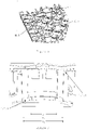
Figure 5 shows a detail of a bottom view of the pavement module with the protective shoe suitably inserted on the outside the first rigid support element. -
Figure 6 shows a cross sectional view of the pavement module with the protective shoe properly inserted in the first rigid support element, showing the maximum outer diameter D1 and maximum outer diameter D3 of the first rigid support element, as well as the maximum inner diameter D4 of the protective shoe. Body and base gaps are also shown. -
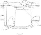
Figure 7 shows a detail from a perspective view of the protective shoe properly fitted to the outside of the first rigid support element, showing the body and base gaps. - Marked in the figures are the elements and components of this invention's equipment, as well as elements necessary for its operation:
- 1 - Protective shoe
- 1.1 - Body of the shoe
1.1.1 - Body gap - 1.2 - Shoe base
1.2.1 - Base gap - 1.3 - Shoe grooves
- 1.1 - Body of the shoe
- 2 - Impact absorber
- M - Pavement module
- M.1 - Top surface layer
- M.2 - First rigid support element
- M.3 - Second rigid support element
- M.4 - Recess
- The term modular' refers to objects of regular or standardized units or dimensions that provide multiple components for the assembly of flexible arrangements and uses.
- 'Resilient' means an object capable of returning to its original shape or position after being compressed.
- 'Rigid' means stiff or with a lack of flexibility. However, a 'rigid' support system can flex or compact slightly under load, although to a lesser degree than a 'resilient' support system.
- The upper' surface of a pavement module means the surface that is exposed when the pavement module is placed on a support.
- Impact absorption' means the ability to smooth or dampen shock forces and dissipate kinetic energy.
- 'Laying base' means the surface on which the pavement module or impact absorber is supported. In this invention, depending on the embodiment, the 'laying base' may be the pavement or the protective shoe.
- The shapes 'substantially cylindrical', 'substantially circular' are understood to be preferential shapes for the embodiment of the invention, which may work with other formats.
- A 'substantially centered' position is understood as a preferential position for the embodiment of the invention, which may work with other positions.
- The application of the principles described herein is not limited to the specific embodiments presented.
- The principles described herein can be used with any covering system.
- Additionally, although some of the embodiments presented incorporate multiple new characteristics, the characteristics can be independent and do not all need to be used together in a single embodiment.
- Pavement systems in accordance with the principles described herein may comprise any number of the presented characteristics.
- Referencing the figures, the invention refers to a protective equipment against wear of rigid support elements or impact absorbers, intended to be used in pavement modules, especially in interconnected modules that form the covering of a pavement.
- One aspect of this invention refers to a system of modules for pavements that includes a pavement module and a plurality of wear protectors for the rigid supporting elements connected to the pavement module.
- The pavement module may have a construction in which the top surface is open, a solution usually used in pavements used in outdoor enclosures, or a construction in which the upper surface is closed, a solution usually used in indoor enclosures.
- The protectors are mounted on the bottom surface of the pavement module.
- The protector consists of a protective shoe (1). The aforementioned protective shoe (1) consists of the body of the shoe (1.1) which is substantially cylindrical in shape, with a first extremity open and a second extremity attached to the shoe base (1.2). The body of the shoe (1.1) has a plurality of shoe grooves (1.3) that fit into the second rigid support elements (M.3) of the pavement module (M). The shoe base (1.2) has a substantially circular shape and is attached to the second extremity of the body of the shoe (1.1) .
- The pavement module (M) comprises an upper surface enclosed by a layer of the top surface (M.1), a plurality of first rigid support elements (M.2), a plurality of second rigid support elements (M.3) and a plurality of recesses (M.4).
- The protective shoe (1) is sized so that the first rigid support element (M.2) fits inside it. Therefore, the maximum outer diameter D3 of the first rigid support element (M.2) must be equal to or slightly smaller than the maximum inner diameter D4 of the protective shoe (1).
- Individually mounted protectors on the pavement module (M) do not have to occupy all the first rigid support elements (M.2), so the number of buffers mounted on the pavement module (M) can vary between 1 and the number of first rigid support elements (M.2) in the pavement module (M).
- In a first embodiment, the protective shoe (1) is placed on the outside of the first rigid support element (M.2), so that the outer walls of the first rigid support element (M.2) are in contact with the inner walls of the body of the shoe (1.1) . The shoe grooves (1.3) fit into the second rigid support elements (M.3) of the pavement module (M).
- When the second rigid supporting elements (M.3) fit into shoe grooves (1.3) and the body of the shoe (1.1) surrounds the first rigid supporting element (M.2), a base gap (1.2.1) is formed, i.e., there is a space between the second rigid supporting element (M.3) and the shoe base (1.2), which allows the second rigid support element (M.3) to descend when a force is exerted on the pavement module (M) until, at most, it touches the shoe base (1.2). At the same time, due to the body gap (1.1.1), i.e., the space between the body of the shoe (1.1) and the pavement module (M), when a force is exerted on the pavement module (M), the pavement module (M) descends until, at most, it touches the body of the shoe (1.1) .
- In a second embodiment in which impact absorbers are inserted (2) inside the first rigid support element (M.2), i.e., in the recess (M.4), the protective shoe (1) is placed outside the first rigid support element (M.2) after the impact absorber is placed (2), in which case the protective shoe (1) works as a wear protector of the impact absorber (2).
- The protector is made of a non-resilient material, namely but not limited to polypropylene. Many other suitable materials are possible.
Claims (6)
- Modular pavement system with a wear-protective system consisting of:- a pavement module (M) comprising a layer of a upper surface (M.1), a plurality of a first rigid support elements (M.2), a plurality of a second rigid support elements (M.3) and a plurality of recesses (M.4), and- a wear protection systemwherein the wear protective system consists of at least one protective shoe (1) consisting of a body of the shoe (1.1) involving the first rigid support element (M.2) of the pavement module (M), a shoe base (1.2) which is supported by a laying base and a plurality of a shoe grooves (1.3) which fit into the second rigid support elements (M.3) of the pavement module (M).
- Modular pavement system according to claim 1 wherein the protective shoe (1) has the appropriate dimensions so that the first rigid support element (M.2) fits inside it.
- Modular pavement system according to claim 1 wherein the installation of the protective shoe (1) forming a base gap (1.2.1) in the space between the second rigid support element (M.3) and the shoe base (1.2).
- Modular pavement system according to claim 3 wherein the base gap (1.2.1) enables the second rigid supporting element (M.3) to descend until, at most, it touches the shoe base (1.2) when a force is applied to the pavement module (M).
- Modular pavement system according to claim 1 wherein the installation of the protective shoe (1) forms a body gap (1.1.1) in the space between the body of the shoe (1.1) and the pavement module (M).
- Modular pavement system according to claim 5 wherein when a force is exerted on the pavement module (M), the pavement module (M) descends until, at most, it touches the body of the shoe (1.1).
Applications Claiming Priority (2)
| Application Number | Priority Date | Filing Date | Title |
|---|---|---|---|
| PT111115A PT111115B (en) | 2018-08-31 | 2018-08-31 | MODULAR SYSTEM FOR FLOORING WITH RESILIENT DAMPING SYSTEM |
| PCT/IB2019/057321 WO2020044300A2 (en) | 2018-08-31 | 2019-08-30 | Modular pavement system with a wear-protective system |
Publications (3)
| Publication Number | Publication Date |
|---|---|
| EP4047130A2 true EP4047130A2 (en) | 2022-08-24 |
| EP4047130C0 EP4047130C0 (en) | 2023-12-20 |
| EP4047130B1 EP4047130B1 (en) | 2023-12-20 |
Family
ID=68426544
Family Applications (2)
| Application Number | Title | Priority Date | Filing Date |
|---|---|---|---|
| EP19798715.9A Active EP4047130B1 (en) | 2018-08-31 | 2019-08-30 | Modular pavement system with a wear-protective system |
| EP19797790.3A Active EP4047129B1 (en) | 2018-08-31 | 2019-08-30 | Modular system for pavement with resilient cushioning system |
Family Applications After (1)
| Application Number | Title | Priority Date | Filing Date |
|---|---|---|---|
| EP19797790.3A Active EP4047129B1 (en) | 2018-08-31 | 2019-08-30 | Modular system for pavement with resilient cushioning system |
Country Status (5)
| Country | Link |
|---|---|
| US (2) | US11932997B2 (en) |
| EP (2) | EP4047130B1 (en) |
| BR (2) | BR112021003854B1 (en) |
| PT (1) | PT111115B (en) |
| WO (2) | WO2020044299A2 (en) |
Cited By (1)
| Publication number | Priority date | Publication date | Assignee | Title |
|---|---|---|---|---|
| WO2025186350A1 (en) * | 2024-03-05 | 2025-09-12 | PURUS PLASTICS GmbH | Adapter as insert for a plastic grating multi-purpose module |
Families Citing this family (3)
| Publication number | Priority date | Publication date | Assignee | Title |
|---|---|---|---|---|
| PT111115B (en) * | 2018-08-31 | 2020-05-13 | Emília Marta Machado Maria | MODULAR SYSTEM FOR FLOORING WITH RESILIENT DAMPING SYSTEM |
| BR102021000903B1 (en) * | 2021-01-18 | 2022-05-24 | Modulare Brasil Artefatos Plásticos Ltda | Modular floor with expansion joint and anti-theft system |
| WO2024229546A1 (en) * | 2023-05-08 | 2024-11-14 | Cordeiro De Oliveira Emerson | Air shock absorber for modular floor, and modular floor |
Family Cites Families (19)
| Publication number | Priority date | Publication date | Assignee | Title |
|---|---|---|---|---|
| US4440818A (en) * | 1983-03-30 | 1984-04-03 | Teknor Apex Company | Floor mat connector device |
| US5250340A (en) * | 1990-08-31 | 1993-10-05 | Bohnhoff William W | Mat for stabilizing particulate materials |
| USD442704S1 (en) * | 1998-01-20 | 2001-05-22 | Sian Ghee Alan Lee | Decorative paving article |
| US6585449B2 (en) * | 2001-10-12 | 2003-07-01 | Jui-Wen Chen | Environment protecting gutter duct structure for a concrete roadway |
| US7303800B2 (en) * | 2002-03-22 | 2007-12-04 | Rogers D Scott | Interlocking mat |
| US20090235605A1 (en) * | 2004-10-06 | 2009-09-24 | Thayne Haney | Method of Making A Modular Synthetic Floor Tile Configured For Enhanced Performance |
| CA2706906A1 (en) * | 2004-12-24 | 2006-08-03 | Chang-Sub Son | Grass protection mat and mat assembly |
| US8099915B2 (en) * | 2005-06-02 | 2012-01-24 | Snapsports Company | Modular floor tile with resilient support members |
| US20090165414A1 (en) * | 2007-12-31 | 2009-07-02 | Tri-Tek Industries | Athletic floor panel system |
| CA2724556A1 (en) * | 2008-05-16 | 2009-11-19 | Alan Sian Ghee Lee | Flexible drainage cell |
| US10369739B2 (en) * | 2013-04-18 | 2019-08-06 | Viconic Sporting Llc | Surface underlayment system with interlocking resilient assemblies of shock tiles |
| US9133628B2 (en) * | 2013-09-19 | 2015-09-15 | Snapsports Company | Multi-stage shock absorbing modular floor tile apparatus |
| KR200472466Y1 (en) * | 2013-10-30 | 2014-04-29 | (주) 에스지아이스 | Floor board for sports |
| US8734049B1 (en) * | 2013-11-22 | 2014-05-27 | Barry J. Stiles | One piece water permeable paver |
| US9962878B2 (en) * | 2015-10-12 | 2018-05-08 | Playsafer Surfacing Llc | Multi-level unitary safety surface tiles |
| US9631375B1 (en) * | 2016-07-11 | 2017-04-25 | 308, Llc | Shock absorbing interlocking floor system |
| US20180080235A1 (en) * | 2016-09-19 | 2018-03-22 | Pliteq Inc. | Shock absorbing mat/tile and floor covering employing the same |
| KR101870386B1 (en) * | 2018-01-15 | 2018-06-22 | (주)하이탑 | Prefabricated flooring with height adjustment and shock absorption |
| PT111115B (en) * | 2018-08-31 | 2020-05-13 | Emília Marta Machado Maria | MODULAR SYSTEM FOR FLOORING WITH RESILIENT DAMPING SYSTEM |
-
2018
- 2018-08-31 PT PT111115A patent/PT111115B/en active IP Right Grant
-
2019
- 2019-08-30 BR BR112021003854-0A patent/BR112021003854B1/en active IP Right Grant
- 2019-08-30 EP EP19798715.9A patent/EP4047130B1/en active Active
- 2019-08-30 WO PCT/IB2019/057320 patent/WO2020044299A2/en not_active Ceased
- 2019-08-30 BR BR112021003855-8A patent/BR112021003855B1/en active IP Right Grant
- 2019-08-30 WO PCT/IB2019/057321 patent/WO2020044300A2/en not_active Ceased
- 2019-08-30 EP EP19797790.3A patent/EP4047129B1/en active Active
-
2021
- 2021-03-01 US US17/188,355 patent/US11932997B2/en active Active
- 2021-03-01 US US17/188,156 patent/US11965292B2/en active Active
Cited By (1)
| Publication number | Priority date | Publication date | Assignee | Title |
|---|---|---|---|---|
| WO2025186350A1 (en) * | 2024-03-05 | 2025-09-12 | PURUS PLASTICS GmbH | Adapter as insert for a plastic grating multi-purpose module |
Also Published As
| Publication number | Publication date |
|---|---|
| EP4047129C0 (en) | 2023-11-22 |
| BR112021003855B1 (en) | 2024-02-27 |
| US20210180269A1 (en) | 2021-06-17 |
| EP4047129A2 (en) | 2022-08-24 |
| PT111115A (en) | 2020-03-02 |
| PT111115B (en) | 2020-05-13 |
| EP4047130C0 (en) | 2023-12-20 |
| EP4047129B1 (en) | 2023-11-22 |
| BR112021003854B1 (en) | 2024-02-27 |
| EP4047130B1 (en) | 2023-12-20 |
| BR112021003855A2 (en) | 2021-08-10 |
| WO2020044300A2 (en) | 2020-03-05 |
| US11965292B2 (en) | 2024-04-23 |
| WO2020044299A3 (en) | 2020-05-14 |
| WO2020044300A4 (en) | 2020-06-25 |
| BR112021003854A2 (en) | 2021-05-18 |
| WO2020044299A4 (en) | 2020-06-25 |
| WO2020044299A2 (en) | 2020-03-05 |
| US20210180268A1 (en) | 2021-06-17 |
| US11932997B2 (en) | 2024-03-19 |
| WO2020044300A3 (en) | 2020-05-14 |
Similar Documents
| Publication | Publication Date | Title |
|---|---|---|
| US11965292B2 (en) | Modular pavement system with a wear-protective system | |
| CN103228163B (en) | With the shock suction layer of separate unit | |
| US7249442B2 (en) | Storage rack vibration isolators and related storage rack systems | |
| US8511004B2 (en) | Seismically stable flooring | |
| US7237364B2 (en) | Foundation shock eliminator | |
| CN100507191C (en) | Isolation platform | |
| KR101384027B1 (en) | Vibration isolation module for earthquake reduction | |
| US20210159933A1 (en) | Mobile device cover with impact absorption structure | |
| CN105696716B (en) | Self-adjusting support pad | |
| US20150075092A1 (en) | Multi-stage shock absorbing modular floor tile apparatus | |
| WO2011152690A2 (en) | Seismic isolation device responding to earthquake having at least certain intensity | |
| US6422290B1 (en) | Damping device for telescopic guards | |
| US20060125161A1 (en) | Foundation shock suppressor | |
| RU97122286A (en) | DRILLING TOOL | |
| KR101291809B1 (en) | Seismic isolation device for a bridge | |
| US20070157532A1 (en) | Foundation shock eliminator | |
| KR101201957B1 (en) | Sliding elastomeric bearing | |
| GB2084694A (en) | A shock and vibration isolation mat | |
| KR101417380B1 (en) | Access floor system | |
| KR200417820Y1 (en) | Shock Absorbing Rubber | |
| KR102683783B1 (en) | a system for floor with member of access floor | |
| KR102731110B1 (en) | 3D seismic isolation bearing with excellent vertical damping performance | |
| KR20160143445A (en) | A vibrating suction device | |
| KR200488018Y1 (en) | access floor assembley | |
| KR100717136B1 (en) | Floorboard support with dustproof cushion structure |
Legal Events
| Date | Code | Title | Description |
|---|---|---|---|
| STAA | Information on the status of an ep patent application or granted ep patent |
Free format text: STATUS: UNKNOWN |
|
| STAA | Information on the status of an ep patent application or granted ep patent |
Free format text: STATUS: THE INTERNATIONAL PUBLICATION HAS BEEN MADE |
|
| PUAI | Public reference made under article 153(3) epc to a published international application that has entered the european phase |
Free format text: ORIGINAL CODE: 0009012 |
|
| STAA | Information on the status of an ep patent application or granted ep patent |
Free format text: STATUS: REQUEST FOR EXAMINATION WAS MADE |
|
| 17P | Request for examination filed |
Effective date: 20210416 |
|
| AK | Designated contracting states |
Kind code of ref document: A2 Designated state(s): AL AT BE BG CH CY CZ DE DK EE ES FI FR GB GR HR HU IE IS IT LI LT LU LV MC MK MT NL NO PL PT RO RS SE SI SK SM TR |
|
| GRAP | Despatch of communication of intention to grant a patent |
Free format text: ORIGINAL CODE: EPIDOSNIGR1 |
|
| STAA | Information on the status of an ep patent application or granted ep patent |
Free format text: STATUS: GRANT OF PATENT IS INTENDED |
|
| INTG | Intention to grant announced |
Effective date: 20230713 |
|
| GRAS | Grant fee paid |
Free format text: ORIGINAL CODE: EPIDOSNIGR3 |
|
| GRAA | (expected) grant |
Free format text: ORIGINAL CODE: 0009210 |
|
| STAA | Information on the status of an ep patent application or granted ep patent |
Free format text: STATUS: THE PATENT HAS BEEN GRANTED |
|
| AK | Designated contracting states |
Kind code of ref document: B1 Designated state(s): AL AT BE BG CH CY CZ DE DK EE ES FI FR GB GR HR HU IE IS IT LI LT LU LV MC MK MT NL NO PL PT RO RS SE SI SK SM TR |
|
| REG | Reference to a national code |
Ref country code: GB Ref legal event code: FG4D |
|
| REG | Reference to a national code |
Ref country code: CH Ref legal event code: EP |
|
| REG | Reference to a national code |
Ref country code: DE Ref legal event code: R096 Ref document number: 602019043686 Country of ref document: DE |
|
| REG | Reference to a national code |
Ref country code: IE Ref legal event code: FG4D |
|
| U01 | Request for unitary effect filed |
Effective date: 20240117 |
|
| U07 | Unitary effect registered |
Designated state(s): AT BE BG DE DK EE FI FR IT LT LU LV MT NL PT SE SI Effective date: 20240129 |
|
| RAP4 | Party data changed (patent owner data changed or rights of a patent transferred) |
Owner name: ISSG SPORTS INNOVATIONS, LDA |
|
| U1H | Name or address of the proprietor changed after the registration of the unitary effect |
Owner name: ISSG SPORTS INNOVATIONS, LDA; PT |
|
| PG25 | Lapsed in a contracting state [announced via postgrant information from national office to epo] |
Ref country code: ES Free format text: LAPSE BECAUSE OF FAILURE TO SUBMIT A TRANSLATION OF THE DESCRIPTION OR TO PAY THE FEE WITHIN THE PRESCRIBED TIME-LIMIT Effective date: 20231220 |
|
| PG25 | Lapsed in a contracting state [announced via postgrant information from national office to epo] |
Ref country code: ES Free format text: LAPSE BECAUSE OF FAILURE TO SUBMIT A TRANSLATION OF THE DESCRIPTION OR TO PAY THE FEE WITHIN THE PRESCRIBED TIME-LIMIT Effective date: 20231220 |
|
| PG25 | Lapsed in a contracting state [announced via postgrant information from national office to epo] |
Ref country code: RS Free format text: LAPSE BECAUSE OF FAILURE TO SUBMIT A TRANSLATION OF THE DESCRIPTION OR TO PAY THE FEE WITHIN THE PRESCRIBED TIME-LIMIT Effective date: 20231220 Ref country code: NO Free format text: LAPSE BECAUSE OF FAILURE TO SUBMIT A TRANSLATION OF THE DESCRIPTION OR TO PAY THE FEE WITHIN THE PRESCRIBED TIME-LIMIT Effective date: 20240320 Ref country code: HR Free format text: LAPSE BECAUSE OF FAILURE TO SUBMIT A TRANSLATION OF THE DESCRIPTION OR TO PAY THE FEE WITHIN THE PRESCRIBED TIME-LIMIT Effective date: 20231220 |
|
| PG25 | Lapsed in a contracting state [announced via postgrant information from national office to epo] |
Ref country code: IS Free format text: LAPSE BECAUSE OF FAILURE TO SUBMIT A TRANSLATION OF THE DESCRIPTION OR TO PAY THE FEE WITHIN THE PRESCRIBED TIME-LIMIT Effective date: 20240420 |
|
| PG25 | Lapsed in a contracting state [announced via postgrant information from national office to epo] |
Ref country code: CZ Free format text: LAPSE BECAUSE OF FAILURE TO SUBMIT A TRANSLATION OF THE DESCRIPTION OR TO PAY THE FEE WITHIN THE PRESCRIBED TIME-LIMIT Effective date: 20231220 |
|
| PG25 | Lapsed in a contracting state [announced via postgrant information from national office to epo] |
Ref country code: SK Free format text: LAPSE BECAUSE OF FAILURE TO SUBMIT A TRANSLATION OF THE DESCRIPTION OR TO PAY THE FEE WITHIN THE PRESCRIBED TIME-LIMIT Effective date: 20231220 |
|
| PG25 | Lapsed in a contracting state [announced via postgrant information from national office to epo] |
Ref country code: SM Free format text: LAPSE BECAUSE OF FAILURE TO SUBMIT A TRANSLATION OF THE DESCRIPTION OR TO PAY THE FEE WITHIN THE PRESCRIBED TIME-LIMIT Effective date: 20231220 Ref country code: SK Free format text: LAPSE BECAUSE OF FAILURE TO SUBMIT A TRANSLATION OF THE DESCRIPTION OR TO PAY THE FEE WITHIN THE PRESCRIBED TIME-LIMIT Effective date: 20231220 Ref country code: RO Free format text: LAPSE BECAUSE OF FAILURE TO SUBMIT A TRANSLATION OF THE DESCRIPTION OR TO PAY THE FEE WITHIN THE PRESCRIBED TIME-LIMIT Effective date: 20231220 Ref country code: IS Free format text: LAPSE BECAUSE OF FAILURE TO SUBMIT A TRANSLATION OF THE DESCRIPTION OR TO PAY THE FEE WITHIN THE PRESCRIBED TIME-LIMIT Effective date: 20240420 Ref country code: CZ Free format text: LAPSE BECAUSE OF FAILURE TO SUBMIT A TRANSLATION OF THE DESCRIPTION OR TO PAY THE FEE WITHIN THE PRESCRIBED TIME-LIMIT Effective date: 20231220 |
|
| PG25 | Lapsed in a contracting state [announced via postgrant information from national office to epo] |
Ref country code: PL Free format text: LAPSE BECAUSE OF FAILURE TO SUBMIT A TRANSLATION OF THE DESCRIPTION OR TO PAY THE FEE WITHIN THE PRESCRIBED TIME-LIMIT Effective date: 20231220 |
|
| PG25 | Lapsed in a contracting state [announced via postgrant information from national office to epo] |
Ref country code: PL Free format text: LAPSE BECAUSE OF FAILURE TO SUBMIT A TRANSLATION OF THE DESCRIPTION OR TO PAY THE FEE WITHIN THE PRESCRIBED TIME-LIMIT Effective date: 20231220 |
|
| REG | Reference to a national code |
Ref country code: DE Ref legal event code: R097 Ref document number: 602019043686 Country of ref document: DE |
|
| U20 | Renewal fee for the european patent with unitary effect paid |
Year of fee payment: 6 Effective date: 20240826 |
|
| PLBE | No opposition filed within time limit |
Free format text: ORIGINAL CODE: 0009261 |
|
| STAA | Information on the status of an ep patent application or granted ep patent |
Free format text: STATUS: NO OPPOSITION FILED WITHIN TIME LIMIT |
|
| 26N | No opposition filed |
Effective date: 20240923 |
|
| REG | Reference to a national code |
Ref country code: CH Ref legal event code: PL |
|
| GBPC | Gb: european patent ceased through non-payment of renewal fee |
Effective date: 20240830 |
|
| PG25 | Lapsed in a contracting state [announced via postgrant information from national office to epo] |
Ref country code: MC Free format text: LAPSE BECAUSE OF FAILURE TO SUBMIT A TRANSLATION OF THE DESCRIPTION OR TO PAY THE FEE WITHIN THE PRESCRIBED TIME-LIMIT Effective date: 20231220 Ref country code: CH Free format text: LAPSE BECAUSE OF NON-PAYMENT OF DUE FEES Effective date: 20240831 |
|
| PG25 | Lapsed in a contracting state [announced via postgrant information from national office to epo] |
Ref country code: GB Free format text: LAPSE BECAUSE OF NON-PAYMENT OF DUE FEES Effective date: 20240830 |
|
| PG25 | Lapsed in a contracting state [announced via postgrant information from national office to epo] |
Ref country code: IE Free format text: LAPSE BECAUSE OF NON-PAYMENT OF DUE FEES Effective date: 20240830 |
|
| U20 | Renewal fee for the european patent with unitary effect paid |
Year of fee payment: 7 Effective date: 20250828 |
|
| PG25 | Lapsed in a contracting state [announced via postgrant information from national office to epo] |
Ref country code: CY Free format text: LAPSE BECAUSE OF FAILURE TO SUBMIT A TRANSLATION OF THE DESCRIPTION OR TO PAY THE FEE WITHIN THE PRESCRIBED TIME-LIMIT; INVALID AB INITIO Effective date: 20190830 |
|
| PG25 | Lapsed in a contracting state [announced via postgrant information from national office to epo] |
Ref country code: HU Free format text: LAPSE BECAUSE OF FAILURE TO SUBMIT A TRANSLATION OF THE DESCRIPTION OR TO PAY THE FEE WITHIN THE PRESCRIBED TIME-LIMIT; INVALID AB INITIO Effective date: 20190830 |