EP4047118A1 - Integrated laundry processing apparatus and control method thereof - Google Patents
Integrated laundry processing apparatus and control method thereof Download PDFInfo
- Publication number
- EP4047118A1 EP4047118A1 EP20877790.4A EP20877790A EP4047118A1 EP 4047118 A1 EP4047118 A1 EP 4047118A1 EP 20877790 A EP20877790 A EP 20877790A EP 4047118 A1 EP4047118 A1 EP 4047118A1
- Authority
- EP
- European Patent Office
- Prior art keywords
- humidity
- inlet
- drying
- hot air
- laundry treatment
- Prior art date
- Legal status (The legal status is an assumption and is not a legal conclusion. Google has not performed a legal analysis and makes no representation as to the accuracy of the status listed.)
- Granted
Links
Images



Classifications
-
- D—TEXTILES; PAPER
- D06—TREATMENT OF TEXTILES OR THE LIKE; LAUNDERING; FLEXIBLE MATERIALS NOT OTHERWISE PROVIDED FOR
- D06F—LAUNDERING, DRYING, IRONING, PRESSING OR FOLDING TEXTILE ARTICLES
- D06F34/00—Details of control systems for washing machines, washer-dryers or laundry dryers
- D06F34/14—Arrangements for detecting or measuring specific parameters
- D06F34/26—Condition of the drying air, e.g. air humidity or temperature
-
- D—TEXTILES; PAPER
- D06—TREATMENT OF TEXTILES OR THE LIKE; LAUNDERING; FLEXIBLE MATERIALS NOT OTHERWISE PROVIDED FOR
- D06F—LAUNDERING, DRYING, IRONING, PRESSING OR FOLDING TEXTILE ARTICLES
- D06F25/00—Washing machines with receptacles, e.g. perforated, having a rotary movement, e.g. oscillatory movement, the receptacle serving both for washing and for centrifugally separating water from the laundry and having further drying means, e.g. using hot air
-
- D—TEXTILES; PAPER
- D06—TREATMENT OF TEXTILES OR THE LIKE; LAUNDERING; FLEXIBLE MATERIALS NOT OTHERWISE PROVIDED FOR
- D06F—LAUNDERING, DRYING, IRONING, PRESSING OR FOLDING TEXTILE ARTICLES
- D06F29/00—Combinations of a washing machine with other separate apparatus in a common frame or the like, e.g. with rinsing apparatus
- D06F29/005—Combinations of a washing machine with other separate apparatus in a common frame or the like, e.g. with rinsing apparatus the other separate apparatus being a drying appliance
-
- D—TEXTILES; PAPER
- D06—TREATMENT OF TEXTILES OR THE LIKE; LAUNDERING; FLEXIBLE MATERIALS NOT OTHERWISE PROVIDED FOR
- D06F—LAUNDERING, DRYING, IRONING, PRESSING OR FOLDING TEXTILE ARTICLES
- D06F33/00—Control of operations performed in washing machines or washer-dryers
- D06F33/50—Control of washer-dryers characterised by the purpose or target of the control
- D06F33/52—Control of the operational steps, e.g. optimisation or improvement of operational steps depending on the condition of the laundry
- D06F33/63—Control of the operational steps, e.g. optimisation or improvement of operational steps depending on the condition of the laundry of air flow, e.g. blowing air during the washing process to prevent entanglement of the laundry
-
- D—TEXTILES; PAPER
- D06—TREATMENT OF TEXTILES OR THE LIKE; LAUNDERING; FLEXIBLE MATERIALS NOT OTHERWISE PROVIDED FOR
- D06F—LAUNDERING, DRYING, IRONING, PRESSING OR FOLDING TEXTILE ARTICLES
- D06F58/00—Domestic laundry dryers
- D06F58/02—Domestic laundry dryers having dryer drums rotating about a horizontal axis
- D06F58/04—Details
-
- D—TEXTILES; PAPER
- D06—TREATMENT OF TEXTILES OR THE LIKE; LAUNDERING; FLEXIBLE MATERIALS NOT OTHERWISE PROVIDED FOR
- D06F—LAUNDERING, DRYING, IRONING, PRESSING OR FOLDING TEXTILE ARTICLES
- D06F58/00—Domestic laundry dryers
- D06F58/20—General details of domestic laundry dryers
- D06F58/24—Condensing arrangements
-
- D—TEXTILES; PAPER
- D06—TREATMENT OF TEXTILES OR THE LIKE; LAUNDERING; FLEXIBLE MATERIALS NOT OTHERWISE PROVIDED FOR
- D06F—LAUNDERING, DRYING, IRONING, PRESSING OR FOLDING TEXTILE ARTICLES
- D06F58/00—Domestic laundry dryers
- D06F58/20—General details of domestic laundry dryers
- D06F58/26—Heating arrangements, e.g. gas heating equipment
-
- D—TEXTILES; PAPER
- D06—TREATMENT OF TEXTILES OR THE LIKE; LAUNDERING; FLEXIBLE MATERIALS NOT OTHERWISE PROVIDED FOR
- D06F—LAUNDERING, DRYING, IRONING, PRESSING OR FOLDING TEXTILE ARTICLES
- D06F58/00—Domestic laundry dryers
- D06F58/32—Control of operations performed in domestic laundry dryers
- D06F58/34—Control of operations performed in domestic laundry dryers characterised by the purpose or target of the control
- D06F58/36—Control of operational steps, e.g. for optimisation or improvement of operational steps depending on the condition of the laundry
- D06F58/38—Control of operational steps, e.g. for optimisation or improvement of operational steps depending on the condition of the laundry of drying, e.g. to achieve the target humidity
-
- D—TEXTILES; PAPER
- D06—TREATMENT OF TEXTILES OR THE LIKE; LAUNDERING; FLEXIBLE MATERIALS NOT OTHERWISE PROVIDED FOR
- D06F—LAUNDERING, DRYING, IRONING, PRESSING OR FOLDING TEXTILE ARTICLES
- D06F58/00—Domestic laundry dryers
- D06F58/32—Control of operations performed in domestic laundry dryers
- D06F58/34—Control of operations performed in domestic laundry dryers characterised by the purpose or target of the control
- D06F58/48—Control of the energy consumption
-
- D—TEXTILES; PAPER
- D06—TREATMENT OF TEXTILES OR THE LIKE; LAUNDERING; FLEXIBLE MATERIALS NOT OTHERWISE PROVIDED FOR
- D06F—LAUNDERING, DRYING, IRONING, PRESSING OR FOLDING TEXTILE ARTICLES
- D06F2103/00—Parameters monitored or detected for the control of domestic laundry washing machines, washer-dryers or laundry dryers
- D06F2103/02—Characteristics of laundry or load
- D06F2103/04—Quantity, e.g. weight or variation of weight
-
- D—TEXTILES; PAPER
- D06—TREATMENT OF TEXTILES OR THE LIKE; LAUNDERING; FLEXIBLE MATERIALS NOT OTHERWISE PROVIDED FOR
- D06F—LAUNDERING, DRYING, IRONING, PRESSING OR FOLDING TEXTILE ARTICLES
- D06F2103/00—Parameters monitored or detected for the control of domestic laundry washing machines, washer-dryers or laundry dryers
- D06F2103/28—Air properties
- D06F2103/34—Humidity
-
- D—TEXTILES; PAPER
- D06—TREATMENT OF TEXTILES OR THE LIKE; LAUNDERING; FLEXIBLE MATERIALS NOT OTHERWISE PROVIDED FOR
- D06F—LAUNDERING, DRYING, IRONING, PRESSING OR FOLDING TEXTILE ARTICLES
- D06F2103/00—Parameters monitored or detected for the control of domestic laundry washing machines, washer-dryers or laundry dryers
- D06F2103/38—Time, e.g. duration
-
- D—TEXTILES; PAPER
- D06—TREATMENT OF TEXTILES OR THE LIKE; LAUNDERING; FLEXIBLE MATERIALS NOT OTHERWISE PROVIDED FOR
- D06F—LAUNDERING, DRYING, IRONING, PRESSING OR FOLDING TEXTILE ARTICLES
- D06F2105/00—Systems or parameters controlled or affected by the control systems of washing machines, washer-dryers or laundry dryers
- D06F2105/30—Blowers
-
- D—TEXTILES; PAPER
- D06—TREATMENT OF TEXTILES OR THE LIKE; LAUNDERING; FLEXIBLE MATERIALS NOT OTHERWISE PROVIDED FOR
- D06F—LAUNDERING, DRYING, IRONING, PRESSING OR FOLDING TEXTILE ARTICLES
- D06F2105/00—Systems or parameters controlled or affected by the control systems of washing machines, washer-dryers or laundry dryers
- D06F2105/32—Air flow control means
-
- D—TEXTILES; PAPER
- D06—TREATMENT OF TEXTILES OR THE LIKE; LAUNDERING; FLEXIBLE MATERIALS NOT OTHERWISE PROVIDED FOR
- D06F—LAUNDERING, DRYING, IRONING, PRESSING OR FOLDING TEXTILE ARTICLES
- D06F58/00—Domestic laundry dryers
- D06F58/02—Domestic laundry dryers having dryer drums rotating about a horizontal axis
-
- D—TEXTILES; PAPER
- D06—TREATMENT OF TEXTILES OR THE LIKE; LAUNDERING; FLEXIBLE MATERIALS NOT OTHERWISE PROVIDED FOR
- D06F—LAUNDERING, DRYING, IRONING, PRESSING OR FOLDING TEXTILE ARTICLES
- D06F58/00—Domestic laundry dryers
- D06F58/20—General details of domestic laundry dryers
-
- Y—GENERAL TAGGING OF NEW TECHNOLOGICAL DEVELOPMENTS; GENERAL TAGGING OF CROSS-SECTIONAL TECHNOLOGIES SPANNING OVER SEVERAL SECTIONS OF THE IPC; TECHNICAL SUBJECTS COVERED BY FORMER USPC CROSS-REFERENCE ART COLLECTIONS [XRACs] AND DIGESTS
- Y02—TECHNOLOGIES OR APPLICATIONS FOR MITIGATION OR ADAPTATION AGAINST CLIMATE CHANGE
- Y02B—CLIMATE CHANGE MITIGATION TECHNOLOGIES RELATED TO BUILDINGS, e.g. HOUSING, HOUSE APPLIANCES OR RELATED END-USER APPLICATIONS
- Y02B40/00—Technologies aiming at improving the efficiency of home appliances, e.g. induction cooking or efficient technologies for refrigerators, freezers or dish washers
Definitions
- the present disclosure relates to an integrated laundry treatment apparatus and a method of controlling the same, and more particularly, to an integrated laundry treatment apparatus, in which a washing machine module configured to perform a washing process and a drying machine module configured to perform a drying process are disposed in a common cabinet, and a met hod of controlling the same.
- a washing machine as a laundry treatment apparatus, refers to an apparatus configured to wash laundry and including a drum disposed in a cabinet and configured to be rotatable, and a drive device configured to rotate the drum.
- the washing machines are classified into a top-loading type washing machine and a front-loading type washing machine depending on a posture of the drum.
- the front-loading washing machine has a laid drum unlike the top-loading washing machine having an upright drum. Therefore, the laundry is loaded into the front-loading washing machine through a front portion of the washing machine.
- the front-loading washing machine has a smaller size and a larger washing capacity than the top-loading washing machine. In addition, because the front-loading washing machine has high washing performance and does not cause a tangle of laundry, the front-loading washing machine is widely used.
- a combo-type drying-washing machine to which a drying function is added by mounting a drying module in the front-loading washing machine, is also widely and commonly used.
- a drying machine which has been developed only for the purpose of drying the laundry, particularly, a front-loading drying machine similar to the front-loading washing machine, is used together with the combo-type washing machine.
- the washing machine and the drying machine may be installed together by being disposed side by side in a horizontal direction.
- the washing machine and the drying machine occupy an excessively large horizontal area.
- Chinese Patent Application Laid-Open No. 108950976 discloses an integrated laundry treatment apparatus in which a washing machine and a drying machine are assembled by being stacked together in a single cabinet, and the washing machine and the drying machine share some constituent components for implementing functions of a product, thereby reducing an overall size of the product, particularly, an overall height of the product.
- the related document discloses a configuration for sharing a drive motor and a drying module which are common components for the washing machine and the drying machine.
- the shared drying module includes a common duct, a condenser, a heater, a fan, and a motor which are disposed in the common duct, and inlet and outlet valves configured to switch an outlet and an inlet of the common duct.
- the common drying module may supply hot air to a washing drum and a drying drum by adjusting an inlet valve and an outlet valve to perform drying processes simultaneously in the washing machine and the drying machine, and the common drying module may recover the hot air.
- the related document does not disclose a means for adjusting and controlling the amount of hot air to be supplied to the washing drum and the drying drum while performing the drying processes simultaneously in the washing drum and the drying drum.
- the present disclosure has been made in an effort to solve the above-mentioned problems, and an object of the present disclosure is to provide an integrated laundry treatment apparatus, in which a washing machine module and a drying machine module are integrally installed in a common cabinet, and a single drying module is provided to produce dry hot air, such that a size of a product may be reduced, a dried state of laundry being dried in a washing drum and a drying drum is detected in real time while drying processes are simultaneously performed in the washing drum and the drying drum by the common drying module, and the amount of supplied dry hot air and the amount of recovered dry hot air are differently controlled, such that an overall drying process time may be reduced and electric power consumption may be minimized, and the drying processes performed in the drying process and the drying machine of the washing machine are simultaneously completed, such that convenience for a user may be improved, and a method of controlling the same.
- an integrated laundry treatment apparatus including: a cabinet having a common accommodation space therein; a first laundry treatment module disposed at an upper side in the common accommodation space; a second laundry treatment module disposed at a lower side in the common accommodation space; a common drying module configured to produce hot air and supply the hot air to the first laundry treatment module and the second laundry treatment module through a first outlet and a second outlet, the common drying module being configured to absorb at least a part of moisture contained in hot air recovered from the first laundry treatment module and the second laundry treatment module through a first inlet and a second inlet; an outlet flow path switching valve configured to selectively open at least any one of the first outlet and the second outlet or simultaneously open the first outlet and the second outlet; an inlet flow path switching valve configured to selectively open at least any one of the first inlet and the second inlet or simultaneously open the first inlet and the second inlet; a first humidity sensor configured to measure a first humidity of the hot air recovered through the first inlet; a second humidity sensor
- the integrated laundry treatment apparatus may further include: a hot air supply duct including a first supply duct configured to fluid-connect the first outlet and the first laundry treatment module, and a second supply duct configured to fluid-connect the second outlet and the second laundry treatment module; and a hot air recovery duct including a first recovery duct configured to fluid-connect the first inlet and the first laundry treatment module, a second recovery duct configured to fluid-connect the second inlet and the second laundry treatment module.
- first humidity sensor may be disposed adjacent to the first inlet and installed in the first recovery duct
- second humidity sensor may be disposed adjacent to the second inlet and installed in the second recovery duct
- the common drying module may include: a common duct having a hot air flow path therein and having the first and second inlets and the first and second outlets; a heater and a blower fan disposed in the common duct and configured to produce hot air to be discharged to the first outlet and the second outlet; and a condenser configured to absorb at least a part of moisture contained in the hot air recovered through the first inlet and the second inlet.
- control unit may compare the first humidity and the second humidity with a predetermined target humidity before calculating the difference value between the first humidity and the second humidity, and calculate the difference value between the humidities when the control unit determines that both the first humidity and the second humidity exceed the target humidity.
- the target humidity may be a relative humidity of 60%.
- the predetermined critical value may be a relative humidity of 10%.
- the integrated laundry treatment apparatus may further include: a first actuator electrically connected to the control unit and configured to operate the outlet flow path switching valve on the basis of the control signal of the control unit; and a second actuator electrically connected to the control unit and configured to operate the inlet flow path switching valve on the basis of the control signal of the control unit.
- control unit may produce a control signal for increasing the opening degree of the first outlet by a predetermined ratio and decreasing the opening degree of the second outlet by the predetermined ratio when the first humidity is higher than the second humidity, and the control unit may transmit the control signal to the first actuator and the second actuator, and in which the control unit may produce a control signal for increasing the opening degree of the second outlet by the predetermined ratio and decreasing the opening degree of the first outlet by the predetermined ratio when the second humidity is higher than the first humidity, and the control unit may transmit the control signal to the first actuator and the second actuator.
- control unit may produce a control signal for increasing the opening degree of the first inlet by the predetermined ratio and decreasing the opening degree of the second inlet by the predetermined ratio when the first humidity is higher than the second humidity, and the control unit may transmit the control signal to the first actuator and the second actuator, and in which the control unit may produce a control signal for increasing the opening degree of the second inlet by the predetermined ratio and decreasing the opening degree of the first inlet by the predetermined ratio when the second humidity is higher than the first humidity, and the control unit may transmit the control signal to the first actuator and the second actuator.
- the present disclosure provides a method of controlling an integrated laundry treatment apparatus, the method including: a simultaneous drying process step of simultaneously supplying hot air through first and second outlets of a common drying module to first and second laundry treatment modules respectively disposed upper and lower sides in a common accommodation space in a cabinet and absorbing at least a part of moisture contained in hot air recovered through first and second inlets of the common drying module from the first and second laundry treatment modules; a humidity measuring step of measuring a relative humidity of the hot air recovered through the first and second inlets; a humidity difference value determining step of calculating a difference value between the measured humidities and determining whether the calculated difference value exceeds a predetermined critical value; and a flow path opening ratio adjusting step of adjusting a ratio of the hot air to be supplied to the first laundry treatment module and the second laundry treatment module by changing opening degrees of the first and second outlets when the difference value exceeds the predetermined critical value.
- the humidity measuring step may include: a first humidity measuring step of measuring a first humidity of hot air discharged from the first laundry treatment module by using a first humidity sensor disposed adjacent to the first inlet; and a second humidity measuring step of measuring a second humidity of hot air discharged from the second laundry treatment module by using a second humidity sensor disposed adjacent to the second inlet.
- the humidity measuring step may further include a target humidity reach determining step of comparing the first humidity and the second humidity with a predetermined target humidity and determining whether the first humidity and the second humidity are equal to or lower than the target humidity.
- the humidity difference value determining step may be performed when the determination result indicates that both the first humidity and the second humidity exceed the target humidity.
- the target humidity may be a relative humidity of 60%.
- the predetermined critical value may be a relative humidity of 10%.
- the flow path opening ratio adjusting step may include an outlet flow path opening ratio adjusting step of increasing the opening degree of the first outlet by a predetermined ratio and decreasing the opening degree of the second outlet by the predetermined ratio when the first humidity is higher than the second humidity, and increasing the opening degree of the second outlet by the predetermined ratio and decreasing the opening degree of the first outlet by the predetermined ratio when the second humidity is higher than the first humidity.
- the flow path opening ratio adjusting step may include an inlet flow path opening ratio adjusting step of increasing the opening degree of the first inlet by the predetermined ratio and decreasing the opening degree of the second inlet by the predetermined ratio when the first humidity is higher than the second humidity, and increasing the opening degree of the second inlet by the predetermined ratio and decreasing the opening degree of the first inlet by the predetermined ratio when the second humidity is higher than the first humidity.
- the method may further include after the flow path opening ratio adjusting step, a simultaneous drying process step of simultaneously supplying the hot air through the first and second outlets, in a state in which the opening degrees of the first and second inlets and the opening degrees of the first and second outlets are adjusted by the predetermined ratio, and absorbing at least a part of moisture contained in the hot air recovered through the first and second inlets.
- the method may further include a simultaneous process performing time determining step of determining whether a predetermined time has elapsed after simultaneous drying processes are initiated in a state in which the opening degrees of the first and second inlets and the opening degrees of the first and second outlets are adjusted by the predetermined ratio.
- the humidity measuring step, the target humidity reach determining step, the humidity difference value determining step, and the flow path opening ratio adjusting step may be performed again.
- the dried state of the laundry being dried in the first laundry treatment module and the second laundry treatment module is detected in real time while the drying processes are simultaneously performed by the common drying module, and the amount of supplied dry hot air and the amount of recovered dry hot air are differently controlled for the respective treatment modules, such that the overall drying process time may be reduced and electric power consumption may be minimized, and the drying process in the washing machine and the drying process in the drying machine are simultaneously completed, such that the convenience for the user may be improved.
- first and second may be used to describe various constituent elements, but the constituent elements may not be limited by the terms. These terms are used only to distinguish one constituent element from another constituent element.
- a first component may be named a second component, and similarly, the second component may also be named the first component, without departing from the scope of the present disclosure.
- FIG. 1 is a perspective view of an integrated laundry treatment apparatus 1 according to the embodiment of the present disclosure.
- the integrated laundry treatment apparatus 1 includes a common cabinet 10 configured to define an external appearance and having a common accommodation space therein, a first laundry treatment module 20 disposed at an upper side of the common accommodation space, a second laundry treatment module 30 disposed at a lower side of the common accommodation space, and a control panel 40 configured to define a front side of the common cabinet 10 and disposed between the first laundry treatment module 20 and the second laundry treatment module 30.
- the first and second laundry treatment modules 20 and 30, which independently perform the laundry treatment processes, are installed by being integrally stacked in an upward/downward direction in the common cabinet 10, and the first and second laundry treatment modules 20 and 30 share at least some functional components. Therefore, it is possible to remarkably reduce a size, particularly, a size in a height direction of the laundry treatment apparatus in comparison with the related art in which a washing machine and a drying machine are merely stacked.
- first and second laundry treatment modules 20 and 30 are disposed in the upward/downward direction, a front-loading integrated laundry treatment apparatus is suitable instead of a top-loading integrated laundry treatment apparatus.
- the first and second laundry treatment modules 20 and 30 respectively include first and second doors 21 and 31 disposed at the front side of the common cabinet 10.
- a first drum 22 for treating the laundry is disposed inside the first door 21, and a second drum 32 for treating the laundry is disposed inside the second door 31.
- the first and second laundry treatment modules 20 and 30 may perform the same laundry treatment process or different laundry treatment processes.
- a combination of an upper washing machine module and a lower washing machine module, a combination of an upper drying machine module and a lower drying machine module, a combination of an upper washing machine module and a lower drying machine module, and a combination of an upper drying machine module and a lower washing machine module may be applied.
- a drying machine module 20 is provided as the first laundry treatment module disposed at the upper side, and a washing machine is provided as the second laundry treatment module disposed at the lower side.
- the control panel 40 is installed at the front side of the common cabinet 10 and disposed at a position between the drying machine module 20 and the washing machine module 30 in consideration of convenience and accessibility for a user's operation.
- the control panel 40 includes a manipulation unit 41 into which the user's operation command is inputted, and a display unit 42 configured to display current states of the drying machine module 20 and the washing machine module 30, a process performing situation, and the like.
- the control panel 40 is electrically connected to a control unit 70 to be described below, converts the user's operation command, which is inputted through the manipulation unit 41, into an electrical signal, and transmits the electrical signal to the control unit 70.
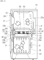
- FIG. 2 is a schematic cross-sectional view of FIG. 1 and illustrates a state in which dry hot air is supplied simultaneously to the drying machine module 20 and the washing machine module 30 through a common drying module 50.
- the integrated laundry treatment apparatus 1 includes the common drying module 50 configured to supply the hot air simultaneously or independently to the drying machine module 20 and the washing machine module 30 and absorb and remove at least a part of moisture contained in the hot air recovered from the drying machine module 20 and the washing machine module 30.
- the common drying module 50 includes a common duct 51 having a common flow path therein.
- the common duct 51 has a first outlet 51c and a second outlet 51d provided to supply dry hot air to the drying machine module 20 and the washing machine module 30, and a first inlet 51a and a second inlet 5 1b provided to recover hot air from the drying machine module 20 and the washing machine module 30.
- a hot air supply flow path and a hot air recovery flow path may be disposed between the drying machine module 20 and the washing machine module 30 in the upward/downward direction and optimized to prevent a thermal loss, but the present disclosure is not limited thereto.
- the first outlet 51c of the common drying module 50 is connected to one end of a first supply duct 61 for guiding the hot air discharged from the common duct 51 to the drying machine module 20, and the second outlet 51d of the common drying module 50 is connected to one end of a second supply duct 62 for guiding the hot air discharged from the common duct 51 to the washing machine module 30. That is, as illustrated, the hot air passing through the common duct 51 of the common drying module 50 is divided into hot air supply ducts including the first supply duct 61 and the second supply duct 62, and the first supply duct 61 and the second supply duct 62 are respectively connected to the drying machine module 20 and the washing machine module 30.
- the other end of the first supply duct 61 is connected to the drying machine module 20, more specifically, an inlet port 22a of the drying drum 22, and the other end of the second supply duct 62 is connected to the washing machine module 30, more specifically, an inlet port 33a of a washing machine tub 33.
- the first inlet 51a of the common drying module 50 is connected to one end of a first recovery duct 63 for guiding the hot air discharged from the drying machine module 20 to the common duct 51
- the second inlet 51b of the common drying module 50 is connected to one end of a second recovery duct 64 for guiding the hot air discharged from the washing machine module 30 to the common duct 51. That is, as illustrated, a flow path structure is formed such that the hot air recovered through the hot air recovery ducts including the first recovery duct 63 and the second recovery duct 64 is merged into the common duct 51.
- the other end of the first recovery duct 63 is connected to a discharge port 22b of the drying drum 22, and the other end of the second recovery duct 64 is connected to a discharge port 33b of the washing machine tub 33.
- a heater 53 and a blower fan 54, which produce the hot air, are disposed in the common duct 51. Further, a condenser 52 is disposed at an upstream side of the heater 53 based on a flow direction of the hot air and serves to remove at least a part of moisture contained in the hot air recovered from the drying machine module 20 and the washing machine module 30.
- a blower motor 55 is installed outside the common duct 51 and disposed adjacent to the blower fan 54.
- the blower motor 55 serves to operate the blower fan 54.
- the blower fan 54 may receive driving power from the separate blower motor 55 dedicated to operating the blower fan 54.
- the blower fan 54 may receive driving power from a drive motor for the washing drum 32 or a drive motor for the drying drum 22.
- the blower fan 54 is operated by the blower motor 55 dedicated to operating the blower fan 54.
- any means already publicly known in the art may be applied to the detailed configuration of the heater 53 and the condenser 52.
- an electrothermal heater 53, a gas heater 53, a heat-pump-type condenser, or the like may be applied as the heater 53 as a heat source.
- a water-cooled dehumidification means, a heat-pump-type evaporator, or the like may be applied as the condenser 52.
- the heater 53 and the condenser 52 which are implemented as a heat pump module 80 will be described, but the present disclosure is not limited thereto.
- an outlet flow path switching valve V2 is installed at an outlet side of the common duct 51 and selectively opens at least any one of the first outlet 51c and the second outlet 51d or simultaneously opens the first outlet 51c and the second outlet 51d.
- An inlet flow path switching valve V1 is installed at an inlet side of the common duct 51 and selectively opens at least any one of the first inlet 51a and the second inlet 51b or simultaneously opens the first inlet 51a and the second inlet 51b.
- the integrated laundry treatment apparatus 1 has at least four process modes.
- the outlet flow path switching valve V2 serves to switch an outlet flow path of the common drying module 50 so that the hot air is supplied only to at least any one of the first outlet 51c and the second outlet 51d of the common duct 51 or the hot air is supplied to both the first outlet 51c and the second outlet 5 1d for the respective process modes.
- the inlet flow path switching valve V1 serves to switch an inlet flow path of the common drying module 50 so that the hot air is recovered only through at least any one of the first inlet 51a and the second inlet 51b of the common duct 51 or the hot air is recovered through both the first inlet 51a and the second inlet 51b for the respective process modes.
- the outlet flow path switching valve V2 and the inlet flow path switching valve V1 may adjust opening degrees of the first and second inlets 51a and 51b and the first and second outlets 51c and 51d to control a flow rate of the hot air to be supplied to the drying machine module 20 and the washing machine module 30 in the process mode in which the hot air is supplied to both the drying machine module 20 and the washing machine module 30.
- outlet flow path switching valve V2 and the inlet flow path switching valve V1 are respectively connected to valve actuators A1 and A2 for operating the outlet flow path switching valve V2 and the inlet flow path switching valve V1, and valve positions are controlled by the valve actuators A1 and A2, respectively.
- the outlet flow path switching valve V2 and the inlet flow path switching valve V1 are each provided in the form of a three-way valve.
- any means capable of switching a 3-way flow path and adjusting opening degrees of the inlet and the outlet of the common drying module 50 for the respective process modes may be applied, without limitation, as the outlet flow path switching valve V2, the inlet flow path switching valve V1, and the valve actuators A1 and A2.
- the modified example of course belongs to the scope of the present disclosure.
- valve position control for the respective process modes will be made with reference to FIGS. 3 to 6 .
- the integrated laundry treatment apparatus 1 includes a first humidity sensor SH1 configured to measure a first humidity of the hot air recovered through the first inlet 51a, and a second humidity sensor SH2 configured to measure a second humidity of the hot air recovered through the second inlet 51b.
- the first humidity sensor SH1 serves to check a drying process state of the laundry in the drying drum 22 by measuring the humidity of the hot air discharged from the drying drum 22 of the drying machine module 20.
- the second humidity sensor SH1 serves to check a drying process state of the laundry in the washing drum 32 by measuring the humidity of the hot air discharged from the washing drum 32 and the tub 33 of the washing machine module 30.
- the first humidity sensor SH1 and the second humidity sensor SH1 are electrically connected to the control unit 70.
- a signal related to the first humidity measured by the first humidity sensor SH1 and a signal related to the second humidity measured by the second humidity sensor SH1 are periodically transmitted to the control unit 70.
- control unit 70 may check the dried state of the laundry in the drying drum 22 and the washing drum 32 on the basis of the first humidity and the second humidity while the drying machine module 20 and the washing machine module 30 simultaneously perform the drying processes.
- the control unit 70 creates a control signal for switching the flow path on the basis of the received first and second humidities so that a large amount of hot air may be supplied to a portion where the laundry is less dried, i.e., a portion where the hot air having a higher humidity is discharged.
- the control unit 70 transmits the control signal to the valve actuators A1 and A2, and the actuators A1 and A2 operate the valves on the basis of the corresponding control signal and adjust the opening degrees of the first and second inlets 51a and 51b and the opening degrees of the first and second outlets 51c and 51d.
- the first humidity sensor SH1 and the second humidity sensor SH1 serve to check the dried state of the laundry in the drying drum 22 and the dried state of the laundry in the washing drum 32
- the first humidity sensor SH1 and the second humidity sensor SH1 need to measure a state before a recovery flow path from the drying machine module 20 and a recovery flow path from the washing machine module 30 are merged. Therefore, the first humidity sensor SH1 and the second humidity sensor SH1 may be respectively installed in the first recovery duct 63 and the second recovery duct 64 and disposed adjacent to the first inlet 51a and the second inlet 51b at the upstream positions from the inlet flow path switching valve V1 based on the flow direction of the hot air.
- any means already publicly known in the art and capable of measuring a relative humidity in the air and converting the humidity into an electrical signal may be applied as the first humidity sensor SH1 and the second humidity sensor SH1.
- FIGS. 3 to 6 are schematic configuration views for explaining a state in which the dry hot air is supplied to the drying machine module 20 and the washing machine module 30 or a state in which the supply of the dry hot air is cut off for respective process modes.
- the integrated laundry treatment apparatus 1 may have at least four process modes including first to fourth process modes based on supplied and recovered states of the dry hot air.
- the first process mode is a process mode in which the drying machine module 20 performs the drying process singly and the washing machine module 30 is in a stopped state or performs the washing process.
- the dry hot air is supplied only to the drying machine module 20.
- the second process mode is a process mode in which the washing machine module 30 performs the drying process singly and the drying machine module 20 is in a stopped state. In the second process mode, the dry hot air is supplied only to the washing machine module 30.
- the third process mode is a process mode in which the drying machine module 20 performs the drying process and, at the same time, the washing machine module 30 performs the washing process and then performs the drying process.
- the dry hot air is supplied only to the drying machine module 20 while the washing machine module 30 performs the washing process.
- the hot air supply and recovery flow paths are switched by the outlet flow path switching valve V2 and the inlet flow path switching valve V1 so that the hot air may be simultaneously supplied to the drying machine module 20 and the washing machine module 30.
- the fourth process mode is a process mode in which the drying machine module 20 and the washing machine module 30 simultaneously perform the drying processes and the dry hot air is simultaneously supplied to the drying machine module 20 and the washing machine module 30.
- FIG. 3 illustrates a state in which the dry hot air is supplied only to the drying machine module 20 in the first and third process modes.
- the washing machine module 30 is in the stopped state in the first process mode, and the washing machine module 30 performs the washing process in the third process mode. Therefore, the dry hot air is not supplied to the washing machine module 30, the total amount of dry hot air is supplied only to the drying machine module 20, and the dry hot air is recovered from the drying machine module 20.
- the outlet flow path switching valve V2 is operated by the valve actuator A2 to fully open the first outlet 51c of the common duct 51 and fully close the second outlet 51d of the common duct 51
- the inlet flow path valve is operated by the valve actuator A1 to fully open the first inlet 51a of the common duct 51 and fully close the second inlet 51b of the common duct 51, such that the dry hot air may be supplied only to the drying machine module 20 and the drying machine module 20 may perform the drying process singly. Therefore, as illustrated in FIG. 3 , a single hot air circulation flow path is formed in respect to the drying machine module 20.
- FIG. 3 illustrates an embodiment in which the outlet flow path switching valve V2 and the inlet flow path switching valve V1, which are each a three-way valve, are each provided in the form of a flap valve.
- the embodiment will be described in which the outlet flow path switching valve V2 and the inlet flow path switching valve V1 are each provided in the form of a flap valve, but the present disclosure is not limited thereto.
- the dried state of the laundry in the drying drum 22 is monitored in real time by the first humidity sensor SH1 while the dry hot air is supplied only to the drying machine module 20 by the common drying module 50 in the first and third process modes.
- control unit 70 may perform control to complete the drying process in the drying machine module 20, thereby preventing the laundry from being excessively dried and inhibiting unnecessary electric power consumption.
- FIG. 4 illustrates a state in which the dry hot air is supplied only to the washing machine module 30 in the second process mode.
- the drying machine module 20 since the drying machine module 20 is in the stopped state in the second process mode, the dry hot air is not supplied to the drying machine module 20, and the total amount of dry hot air is supplied only to the washing machine module 30.
- the outlet flow path switching valve V2 is operated by the valve actuator A2 to fully close the first outlet 51c of the common duct 51 and fully open the second outlet 51d of the common duct 51
- the inlet flow path valve is operated by the valve actuator A1 to fully close the first inlet 51a of the common duct 51 and fully open the second inlet 51b of the common duct 51, such that the dry hot air may be supplied only to the washing machine module 30 and the washing machine module 30 may perform the drying process singly. Therefore, as illustrated in FIG. 4 , a single hot air circulation flow path is formed in respect to the washing machine module 30.
- the dried state of the laundry in the washing drum 32 is monitored in real time by the second humidity sensor SH1 in the same way as the first and third process modes while the dry hot air is supplied only to the washing machine module 30 by the common drying module 50 in the second process mode.
- control unit 70 determines that the second humidity measured by the second humidity sensor SH1 reaches a relative humidity of 60%, for example, the control unit 70 performs control to complete the drying process in the washing machine module 30, thereby preventing the laundry from being excessively dried and inhibiting unnecessary electric power consumption.
- FIG. 5 illustrates a state in which the dry hot air is simultaneously supplied to the drying machine module 20 and the washing machine module 30 in the third and fourth process modes.
- the dry hot air is simultaneously supplied to the drying machine module 20 and the washing machine module 30 and simultaneously recovered from the drying machine module 20 and the washing machine module 30 so that the washing process of the washing machine module 30 is completed and the drying process is performed while the drying machine module 20 performs the drying process in the third process mode or so that both the drying machine module 20 and the washing machine module 30 perform the drying processes in the fourth process mode.
- the outlet flow path switching valve V2 is operated by the valve actuator A2 to at least partially open the first outlet 51c and the second outlet 51d of the common duct 51
- the inlet flow path valve is operated by the valve actuator A1 to at least partially open the first inlet 51a and the second inlet 51b of the common duct 51, such that the dry hot air may be simultaneously supplied to the drying machine module 20 and the washing machine module 30, and the drying machine module 20 and the washing machine module 30 may simultaneously perform the drying processes. Therefore, as illustrated in FIG. 4 , hot air circulation flow paths are formed in respect to the drying machine module 20 and the washing machine module 30.
- the outlet flow path switching valve V2 is controlled so that the first outlet 51c and the second outlet 51d of the common duct 51 have the same opening degree
- the inlet flow path switching valve V1 is controlled so that the first inlet 51a and the second inlet 5 1b of the common duct 51 have the same opening degree, such that the dry hot air is supplied basically at the same flow rate to the drying drum 22 and the washing drum 32 while the drying drum 22 and the washing drum 32 simultaneously perform the drying process.
- the outlet flow path switching valve V2 and the inlet flow path switching valve V1 may be controlled so that the opening degree of the first inlet 51a is larger than the opening degree of the second inlet 51b and the opening degree of the first outlet 51c is larger than the opening degree of the second outlet 51d, such that a larger amount of dry hot air may be supplied to the drying drum 22 and recovered from the drying drum 22.
- the dried state of the laundry in the drying drum 22 and the dried state of the laundry in the washing drum 32 are respectively monitored in real time by the first humidity sensor SH1 and the second humidity sensor SH1 while the dry hot air is simultaneously supplied to the drying machine module 20 and the washing machine module 30 by the common drying module 50 while the drying machine module 20 and the washing machine module 30 simultaneously perform the drying processes.
- control unit 70 may switch the outlet flow path switching valve V2 and the inlet flow path switching valve V1 to the states illustrated in FIG. 4 so that the drying process in the drying machine module 20 is stopped and the total amount of dry hot air is transmitted to the washing machine module 30, thereby preventing the laundry in the drying drum 22 from being excessively dried and inhibiting unnecessary electric power consumption.
- control unit 70 determines that the second humidity reaches a relative humidity of 60% and the first humidity is lower than a relative humidity of 60%, the control unit 70 switches the outlet flow path switching valve V2 and the inlet flow path switching valve V1 to the states illustrated in FIG. 3 so that the drying process in the washing machine module 30 is stopped and the total amount of dry hot air is transmitted to the drying machine module 20.
- the control unit 70 calculates a difference value between the first humidity and the second humidity.
- the control unit 70 determines that the corresponding difference value exceeds a predetermined critical value, particularly, a relative humidity of 10%
- the control unit 70 performs control to switch the state of the outlet flow path switching valve V2 and the state of the inlet flow path switching valve V1 so that a larger amount of hot air may be supplied to one of the drying machine module 20 and the washing machine module 30 from which the hot air having a higher humidity is discharged.
- control unit 70 determines that the first humidity is higher than the second humidity by a relative humidity of 10%
- the control unit 70 controls the outlet flow path switching valve V2 to increase the opening degree of the first outlet 51c of the common duct 51 by a predetermined ratio and decrease the opening degree of the second outlet 51d by the predetermined ratio
- the control unit 70 controls the inlet flow path switching valve V1 to adjust the opening degrees of the first inlet 51a and the second inlet 51b of the common duct 51 by the same predetermined ratio.
- the predetermined ratio by which the opening degrees of the first and second inlets 51a and 51b and the first and second outlets 51c and 51d of the common duct 51 are adjusted may be about 5%.
- the opening degrees of the first and second inlets 51a and 51b and the first and second outlets 51c and 51d of common duct 51 may be adjusted and the amount of dry hot air may be differently controlled on the basis of the deviation between the first humidity and the second humidity, thereby minimizing electric power consumption caused when the simultaneous drying processes are entirely delayed.
- FIG. 6 illustrates another embodiment of the integrated laundry treatment apparatus 1 according to the present disclosure, in which the inlet flow path switching valve V1 and the outlet flow path switching valve V2 each include two valves.
- the inlet flow path switching valve V1 includes a first inlet flow path switching valve V11 dedicated to opening or closing the first inlet 51a, and a second inlet flow path switching valve V12 dedicated to opening or closing the second inlet 51b.
- the outlet flow path switching valve V2 includes a first outlet flow path switching valve V21 dedicated to opening or closing the first outlet 51c, and a second outlet flow path switching valve V22 dedicated to opening or closing the second outlet 51d.
- the embodiment illustrated in FIG. 6 may be configured such that the drying machine hot air flow paths and the washing machine hot air flow paths may be simultaneously closed.
- the first outlet flow path switching valve V21 and the second outlet flow path switching valve V22 are respectively operated by dedicated valve actuators V21 and V22, and the first inlet flow path switching valve V11 and the second inlet flow path switching valve V12 are respectively operated by dedicated valve actuators V11 and V12.
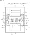
- FIG. 7 is a functional block diagram for explaining the control unit 70 of the integrated laundry treatment apparatus 1 according to the embodiment of the present disclosure
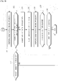
- FIGS. 8 to 9 are flow charts related to a method of controlling the integrated laundry treatment apparatus 1 according to the embodiment of the present disclosure.
- control unit performs a process mode selection signal receiving step S1 of receiving a signal for selecting at least any one of the process modes at least including the first to fourth process modes.
- the control unit 70 receives the signal for selecting the first to fourth process modes on the basis of a selection command physically inputted from the manipulation unit 41 of the control panel 40 illustrated in FIG. 7 .
- the control unit 70 may receive the signal for selecting any one of the first to fourth process modes on the basis of a selection command inputted in a wireless manner through a communication unit CM instead of the control panel 40.
- the communication unit CM is connected to a user mobile device (not illustrated) through any wireless communication means publicly known in the art.
- control unit 70 performs a process mode determining step S2 of determining which process mode is selected among the first to fourth process modes on the basis of the received selection signal.
- control unit 70 may provide the user with information indicating that a particular process mode is selected through the user mobile device or the display unit 42 illustrated in FIG. 7 .
- the control unit 70 performs a drying machine hot air flow path opening step S3 of opening the drying machine hot air flow path as a preparation step for allowing the drying machine module 20 to perform the drying process singly.
- control unit 70 produces the control signal for fully opening the first inlet 51a and the first outlet 51c of the common duct 51 and fully closing the second inlet 51b and the second outlet 51d of the common duct 51, like the state illustrated in FIG. 3 , and transmits the control signal to the valve actuators A1 and A2 illustrated in FIG. 7 .
- control unit 70 performs a drying machine drying process performing step S4 of performing the drying process in the drying machine module 20.
- control unit 70 may check whether the first door 21 of the drying machine module 20 is closed from a sensor for the first door 21 of a sensor unit SM illustrated in FIG. 7 before supplying electric power to a first drive unit 91 of a drive unit 90 for operating the drying drum 22.
- control unit 70 may detect the amount of laundry by initially operating the drying drum 22 by supplying electric power from a power source unit PM to the first drive unit 91.
- the control unit 70 may compare the detected amount of laundry with necessary drying time data for the respective amounts of laundry stored in advance in a memory 71 and transmit information on expected drying process time to the display unit 42 or the user mobile device.
- control unit 70 performs control to produce the dry hot air by supplying the electric power to the heat pump module 80 and the blower motor 55 of the common drying module 50.
- control unit 70 performs control not to supply electric power from the power source unit PM to a second drive unit 92 of the drive unit 90 for operating the washing drum 32.
- the control unit 70 performs a washing machine hot air flow path opening step S5 of opening the washing machine hot air flow path as a preparation step of allowing the washing machine module 30 to perform the drying process singly, as illustrated in FIG. 8 .
- control unit 70 produces the control signal for fully opening the second inlet 51b and the second outlet 51d of the common duct 51 and fully closing the first inlet 51a and the first outlet 51c of the common duct 51, like the state illustrated in FIG. 4 , and transmits the control signal to the valve actuators A1 and A2 illustrated in FIG. 7 .
- control unit 70 performs a washing machine drying process performing step S6 of performing the drying process in the washing machine module 30.
- control unit 70 may check whether the second door 31 of the washing machine module 30 is closed from a sensor for the second door 31 illustrated in FIG. 7 before supplying electric power to the second drive unit 92 for operating the washing drum 32.
- control unit 70 may detect the amount of laundry by initially operating the washing drum 32 by supplying electric power from the power source unit PM to the second drive unit 92.
- the control unit 70 may compare the detected amount of laundry with necessary drying time data for the respective amounts of laundry stored in advance in a memory 71 and transmit information on expected drying process time to the display unit 42 or the user mobile device.
- the expected drying process time of the washing machine module 30 may be different from the drying process time of the drying machine module 20.
- control unit 70 performs control to produce the dry hot air by supplying the electric power to the heat pump module 80 and the blower motor 55 of the common drying module 50.
- control unit 70 performs control not to supply electric power from the power source unit PM to the first drive unit 91 for operating the drying drum 22.
- FIG. 9A and FIG. 9B illustrate steps to be performed by performing the third or fourth process mode among the first to fourth process modes.
- the control unit 70 performs a drying machine hot air flow path opening step S7 of opening the drying machine hot air flow path as a preparation step for allowing the drying machine module 20 to perform the drying process singly.
- the drying machine hot air flow path opening step S7 is performed basically in the same way as the drying machine hot air flow path opening step S3 performed when the first process mode is selected.
- the control unit 70 produces the control signal for fully opening the first inlet 51a and the first outlet 51c of the common duct 51 and fully closing the second inlet 51b and the second outlet 5 1d of the common duct 51 so that the hot air flow path is created only for the drying machine module 20, and the control unit 70 may transmit the control signal to the valve actuators A1 and A2 illustrated in FIG. 7 .
- control unit 70 may perform a drying machine drying/washing machine washing process performing step S8 of performing the drying process in the drying machine module 20 and the washing process in the washing machine module 30.
- control unit 70 may check whether the first door 21 and the second door 31 are closed from the sensor for the first door 21 and the sensor for the second door 31 illustrated in FIG. 7 before supplying electric power to the first drive unit 91 and the second drive unit 92.
- control unit 70 may detect the amount of laundry in the drying drum 22 and the amount of laundry in the washing drum 32 by initially operating the drying drum 22 and the washing drum 32 by supplying electric power from the power source unit PM to the first drive unit 91 and the second drive unit 92.
- the control unit 70 may compare the detected amount of dried laundry with necessary drying time data for the respective amounts of dried laundry stored in advance in the memory 71 and transmits information on expected drying process time of the drying machine module 20 to the display unit 42 or the user mobile device. Further, the control unit 70 may compare the detected amount of washed laundry with necessary drying time data for the respective amounts of washed laundry stored in advance in the memory 71 and transmit information on expected washing process time of the washing machine module 30 to the display unit 42 or the user mobile device.
- control unit 70 performs control to produce the dry hot air by supplying the electric power to the heat pump module 80 and the blower motor 55 of the common drying module 50.
- control unit 70 performs a simultaneous drying processes entering determining step S9 of determining whether the washing process in the washing machine module 30 is completed, whether to supply the dry hot air to the washing machine module 30, and whether the simultaneous drying processes enter.
- washing process in the washing machine module 30 is completed is determined during the drying process in the drying machine module 20.
- control unit 70 determines that the drying process in the drying machine module 20 is completed in a state in which the washing process in the washing machine module 30 is not completed, the control unit 70 stops the drying process in the drying machine module 20 and continuously performs the washing process in the washing machine module 30.
- control unit 70 performs control to perform the washing machine hot air flow path opening step S5 of opening the washing machine hot air flow path illustrated in FIG. 8 and perform the washing machine drying process performing step S6.
- the control unit 70 performs a drying machine/washing machine hot air flow path simultaneous opening step S10 of simultaneously opening the drying machine hot air flow path and the washing machine hot air flow path as a preparation step for simultaneously performing the drying processes in the drying machine module 20 and the washing machine module 30.
- control unit 70 may produce the control signal for fully opening the first and second inlets 51a and 51b and the first and second outlets 51c and 51d of the common duct 51 so that the hot air flow paths may be simultaneously created for the drying machine module 20 and the washing machine module 30, and the control unit 70 may transmit the control signal to the valve actuators A1 and A2 illustrated in FIG. 7 .
- the outlet flow path switching valve V2 is operated by the valve actuator A2 to at least partially open the first outlet 51c and the second outlet 51d of the common duct 51
- the inlet flow path valve is operated by the valve actuator A1 to at least partially open the first inlet 51a and the second inlet 51b of the common duct 51, such that the dry hot air may be simultaneously supplied to the drying machine module 20 and the washing machine module 30, and the drying machine module 20 and the washing machine module 30 may simultaneously perform the drying processes.
- the outlet flow path switching valve V2 is controlled so that the first outlet 51c and the second outlet 51d of the common duct 51 have the same opening degree
- the inlet flow path switching valve V1 is controlled so that the first inlet 51a and the second inlet 51b of the common duct 51 have the same opening degree, such that the dry hot air is supplied basically at the same flow rate to the drying drum 22 and the washing drum 32 while the drying drum 22 and the washing drum 32 simultaneously perform the drying process.
- control unit 70 performs a drying machine/washing machine simultaneous drying processes performing step S11 of performing the drying processes simultaneously in the drying machine module 20 and the washing machine module 30.
- control unit 70 performs a humidity measuring step S12 of measuring, in real time, a relative humidity of the hot air recovered through the first inlet 51a and the second inlet 51b of the common drying module 50.
- the control unit 70 performs a first humidity measuring step of measuring, in real time, the first humidity by using the first humidity sensor SH1 to check the dried state of the laundry in the drying drum 22, and a first humidity measuring step of measuring, in real time, the second humidity by using the second humidity sensor SH1 to check the dried state of the laundry in the washing drum 32.
- control unit 70 may switch the outlet flow path switching valve V2 and the inlet flow path switching valve V1 to the states illustrated in FIG. 4 so that the drying process in the drying machine module 20 is stopped and the total amount of dry hot air is transmitted to the washing machine module 30, thereby preventing the laundry in the drying drum 22 from being excessively dried and inhibiting unnecessary electric power consumption.
- control unit 70 determines that the second humidity reaches a relative humidity of 60% and the first humidity is lower than a relative humidity of 60%, the control unit 70 performs control to switch the outlet flow path switching valve V2 and the inlet flow path switching valve V1 to the states illustrated in FIG. 3 so that the drying process in the washing machine module 30 is stopped and the total amount of dry hot air is transmitted to the drying machine module 20.
- control unit 70 performs a humidity difference value determining step S13 of calculating a difference value between the first humidity and the second humidity and determining whether the corresponding difference value exceeds a predetermined critical value, particularly, a relative humidity of 10%.
- the control unit 70 perform control to continuously perform the drying time drying machine/washing machine simultaneous drying processes performing step S1 until the first humidity and the second humidity reach a target humidity.
- the control unit 70 performs a flow path opening ratio adjusting step S14 of adjusting a ratio of the hot air supplied to the drying machine module 20 and the washing machine module 30 by changing the opening degrees of the first outlet 51c and the second outlet 51d of the common duct 51.
- control unit 70 performs control to switch the state of the outlet flow path switching valve V2 and the state of the inlet flow path switching valve V1 so that a larger amount of hot air may be supplied to one of the drying machine module 20 and the washing machine module 30 from which the hot air having a higher humidity is discharged.
- control unit 70 determines that the first humidity is higher than the second humidity by a relative humidity of 10%
- the control unit 70 controls the outlet flow path switching valve V2 to increase the opening degree of the first outlet 51c of the common duct 51 by a predetermined ratio and decrease the opening degree of the second outlet 51d by the predetermined ratio
- the control unit 70 controls the inlet flow path switching valve V1 to adjust the opening degrees of the first inlet 51a and the second inlet 51b of the common duct 51 by the same predetermined ratio.
- the predetermined ratio by which the opening degrees of the first and second inlets 51a and 51b and the first and second outlets 51c and 51d of the common duct 51 are adjusted may be about 5%.
- a drum rotational speed adjusting step S15 of increasing a rotational speed of the drum of one of the drying machine module 20 and the washing machine module 30 from which the hot air having a higher humidity is discharged may be performed in addition to the flow path opening ratio adjusting step S14.
- the control unit 70 continuously performs the drying machine/washing machine simultaneous drying processes performing step S16 in the state in which the opening ratio of the flow path and the rotational speed of the drum are adjusted as described above, and the control unit 70 performs a time elapse determining step 17 of determining whether a predetermined time elapses after the adjustment of the opening ratio of the flow path and the rotational speed of the drum is completed.
- the predetermined time may be set as 5 minutes to 10 minutes in consideration of the amount of laundry existing in the drying drum 22 and the washing drum 32 and the current remaining drying process time.
- control unit 70 performs control to perform the humidity measuring step S12 again and end the drying process or perform the humidity difference value determining step S13, the flow path opening ratio adjusting step S14, the drum rotational speed adjusting step S15, and the drying machine/washing machine simultaneous drying processes performing step S16 again depending on the humidity measurement result.
- the control unit 70 performs control to immediately perform the drying machine/washing machine hot air flow path simultaneous opening step S10 simultaneously on the drying machine module 20 and the washing machine module 30 and then perform the above-mentioned subsequent steps.
Landscapes
- Engineering & Computer Science (AREA)
- Textile Engineering (AREA)
- Detail Structures Of Washing Machines And Dryers (AREA)
- Control Of Washing Machine And Dryer (AREA)
Abstract
Description
- The present disclosure relates to an integrated laundry treatment apparatus and a method of controlling the same, and more particularly, to an integrated laundry treatment apparatus, in which a washing machine module configured to perform a washing process and a drying machine module configured to perform a drying process are disposed in a common cabinet, and a met hod of controlling the same.
- In general, a washing machine, as a laundry treatment apparatus, refers to an apparatus configured to wash laundry and including a drum disposed in a cabinet and configured to be rotatable, and a drive device configured to rotate the drum. The washing machines are classified into a top-loading type washing machine and a front-loading type washing machine depending on a posture of the drum.
- The front-loading washing machine has a laid drum unlike the top-loading washing machine having an upright drum. Therefore, the laundry is loaded into the front-loading washing machine through a front portion of the washing machine. The front-loading washing machine has a smaller size and a larger washing capacity than the top-loading washing machine. In addition, because the front-loading washing machine has high washing performance and does not cause a tangle of laundry, the front-loading washing machine is widely used.
- In addition, a combo-type drying-washing machine, to which a drying function is added by mounting a drying module in the front-loading washing machine, is also widely and commonly used.
- However, because the drying module installed in the combo-type drying-washing machine has a limited drying capacity, a significantly large amount of drying time is inevitably required to dry the entire laundry washed completely.
- Therefore, to shorten the drying time, as another laundry treatment apparatus, a drying machine, which has been developed only for the purpose of drying the laundry, particularly, a front-loading drying machine similar to the front-loading washing machine, is used together with the combo-type washing machine.
- The washing machine and the drying machine may be installed together by being disposed side by side in a horizontal direction. However, there is a problem in that the washing machine and the drying machine occupy an excessively large horizontal area.
- Therefore, there have been proposed products in which the washing machine and the drying machine are stacked in a vertical direction, particularly, the drying machine is stacked on the washing machine.
- However, in the case of the configuration in which the washing machine and the drying machine are just stacked in the vertical direction as described above, independent functional modules, particularly, the drying modules need to be provided in the washing machine and the drying machine, which excessively increases a height of a product in which the washing machine and the drying machine are stacked. As a result, there occurs a significantly great restriction on a position at which the washing machine and the drying machine are installed together. For example, if the entire position at which the washing machine and the drying machine are stacked is higher than a height of the general home, the washing machine and the drying machine cannot be installed.
- In this regard, as a related document,
Chinese Patent Application Laid-Open No. 108950976 discloses an integrated laundry treatment apparatus in which a washing machine and a drying machine are assembled by being stacked together in a single cabinet, and the washing machine and the drying machine share some constituent components for implementing functions of a product, thereby reducing an overall size of the product, particularly, an overall height of the product. - The related document discloses a configuration for sharing a drive motor and a drying module which are common components for the washing machine and the drying machine. In particular, the shared drying module includes a common duct, a condenser, a heater, a fan, and a motor which are disposed in the common duct, and inlet and outlet valves configured to switch an outlet and an inlet of the common duct.
- The related document only discloses that the common drying module may supply hot air to a washing drum and a drying drum by adjusting an inlet valve and an outlet valve to perform drying processes simultaneously in the washing machine and the drying machine, and the common drying module may recover the hot air. However, the related document does not disclose a means for adjusting and controlling the amount of hot air to be supplied to the washing drum and the drying drum while performing the drying processes simultaneously in the washing drum and the drying drum.
- Therefore, even though the laundry in any one of the washing drum and the drying drum is completely dried while the drying processes are simultaneously performed in the washing drum and the drying drum, the hot air is inevitably consistently supplied to the drum in which the laundry is completely dried. For this reason, there is a problem in that the laundry is damaged by the hot air or unnecessary electric power consumption is inevitably incurred.
- In addition, it is impossible to check a situation in which the drying processes are performed in the washing drum and the drying drum and recognize a dried state of the laundry. For this reason, the hot air needs to be continuously supplied and the drum needs to be operated for a preset drying time, which causes inefficiency in terms of time and electric power consumption.
- The present disclosure has been made in an effort to solve the above-mentioned problems, and an object of the present disclosure is to provide an integrated laundry treatment apparatus, in which a washing machine module and a drying machine module are integrally installed in a common cabinet, and a single drying module is provided to produce dry hot air, such that a size of a product may be reduced, a dried state of laundry being dried in a washing drum and a drying drum is detected in real time while drying processes are simultaneously performed in the washing drum and the drying drum by the common drying module, and the amount of supplied dry hot air and the amount of recovered dry hot air are differently controlled, such that an overall drying process time may be reduced and electric power consumption may be minimized, and the drying processes performed in the drying process and the drying machine of the washing machine are simultaneously completed, such that convenience for a user may be improved, and a method of controlling the same.
- To achieve the above-mentioned object, the present disclosure provides an integrated laundry treatment apparatus including: a cabinet having a common accommodation space therein; a first laundry treatment module disposed at an upper side in the common accommodation space; a second laundry treatment module disposed at a lower side in the common accommodation space; a common drying module configured to produce hot air and supply the hot air to the first laundry treatment module and the second laundry treatment module through a first outlet and a second outlet, the common drying module being configured to absorb at least a part of moisture contained in hot air recovered from the first laundry treatment module and the second laundry treatment module through a first inlet and a second inlet; an outlet flow path switching valve configured to selectively open at least any one of the first outlet and the second outlet or simultaneously open the first outlet and the second outlet; an inlet flow path switching valve configured to selectively open at least any one of the first inlet and the second inlet or simultaneously open the first inlet and the second inlet; a first humidity sensor configured to measure a first humidity of the hot air recovered through the first inlet; a second humidity sensor configured to measure a second humidity of the hot air recovered through the second inlet; and a control unit electrically connected to the first humidity sensor and the second humidity sensor and configured to produce a control signal for operating the outlet flow path switching valve and the inlet flow path switching valve, in which the control unit receives a signal related to the first humidity measured by the first humidity sensor and a signal related to the second humidity measured by the second humidity sensor while the hot air is simultaneously supplied to the first laundry treatment module and the second laundry treatment module, and in which the control unit calculates a difference value between the first humidity and the second humidity, and when the difference value exceeds a predetermined critical value, the control unit operates the outlet flow path switching valve to change opening degrees of the first and second outlets. With this configuration, it is possible to reduce the overall drying process time and minimize the electric power consumption during the simultaneous drying processes. Further, the drying process of the washing machine and the drying process of the drying machine are simultaneously completed, which makes it possible to improve the convenience for the user.
- In addition, the integrated laundry treatment apparatus may further include: a hot air supply duct including a first supply duct configured to fluid-connect the first outlet and the first laundry treatment module, and a second supply duct configured to fluid-connect the second outlet and the second laundry treatment module; and a hot air recovery duct including a first recovery duct configured to fluid-connect the first inlet and the first laundry treatment module, a second recovery duct configured to fluid-connect the second inlet and the second laundry treatment module.
- In addition, the first humidity sensor may be disposed adjacent to the first inlet and installed in the first recovery duct, and the second humidity sensor may be disposed adjacent to the second inlet and installed in the second recovery duct.
- In addition, the common drying module may include: a common duct having a hot air flow path therein and having the first and second inlets and the first and second outlets; a heater and a blower fan disposed in the common duct and configured to produce hot air to be discharged to the first outlet and the second outlet; and a condenser configured to absorb at least a part of moisture contained in the hot air recovered through the first inlet and the second inlet.
- In addition, the control unit may compare the first humidity and the second humidity with a predetermined target humidity before calculating the difference value between the first humidity and the second humidity, and calculate the difference value between the humidities when the control unit determines that both the first humidity and the second humidity exceed the target humidity.
- In addition, the target humidity may be a relative humidity of 60%.
- In addition, the predetermined critical value may be a relative humidity of 10%.
- In addition, the integrated laundry treatment apparatus may further include: a first actuator electrically connected to the control unit and configured to operate the outlet flow path switching valve on the basis of the control signal of the control unit; and a second actuator electrically connected to the control unit and configured to operate the inlet flow path switching valve on the basis of the control signal of the control unit.
- In addition, the control unit may produce a control signal for increasing the opening degree of the first outlet by a predetermined ratio and decreasing the opening degree of the second outlet by the predetermined ratio when the first humidity is higher than the second humidity, and the control unit may transmit the control signal to the first actuator and the second actuator, and in which the control unit may produce a control signal for increasing the opening degree of the second outlet by the predetermined ratio and decreasing the opening degree of the first outlet by the predetermined ratio when the second humidity is higher than the first humidity, and the control unit may transmit the control signal to the first actuator and the second actuator.
- In addition, the control unit may produce a control signal for increasing the opening degree of the first inlet by the predetermined ratio and decreasing the opening degree of the second inlet by the predetermined ratio when the first humidity is higher than the second humidity, and the control unit may transmit the control signal to the first actuator and the second actuator, and in which the control unit may produce a control signal for increasing the opening degree of the second inlet by the predetermined ratio and decreasing the opening degree of the first inlet by the predetermined ratio when the second humidity is higher than the first humidity, and the control unit may transmit the control signal to the first actuator and the second actuator.
- The present disclosure provides a method of controlling an integrated laundry treatment apparatus, the method including: a simultaneous drying process step of simultaneously supplying hot air through first and second outlets of a common drying module to first and second laundry treatment modules respectively disposed upper and lower sides in a common accommodation space in a cabinet and absorbing at least a part of moisture contained in hot air recovered through first and second inlets of the common drying module from the first and second laundry treatment modules; a humidity measuring step of measuring a relative humidity of the hot air recovered through the first and second inlets; a humidity difference value determining step of calculating a difference value between the measured humidities and determining whether the calculated difference value exceeds a predetermined critical value; and a flow path opening ratio adjusting step of adjusting a ratio of the hot air to be supplied to the first laundry treatment module and the second laundry treatment module by changing opening degrees of the first and second outlets when the difference value exceeds the predetermined critical value.
- In addition, the humidity measuring step may include: a first humidity measuring step of measuring a first humidity of hot air discharged from the first laundry treatment module by using a first humidity sensor disposed adjacent to the first inlet; and a second humidity measuring step of measuring a second humidity of hot air discharged from the second laundry treatment module by using a second humidity sensor disposed adjacent to the second inlet.
- In addition, the humidity measuring step may further include a target humidity reach determining step of comparing the first humidity and the second humidity with a predetermined target humidity and determining whether the first humidity and the second humidity are equal to or lower than the target humidity.
- In addition, the humidity difference value determining step may be performed when the determination result indicates that both the first humidity and the second humidity exceed the target humidity.
- In addition, the target humidity may be a relative humidity of 60%.
- In addition, the predetermined critical value may be a relative humidity of 10%.
- In addition, the flow path opening ratio adjusting step may include an outlet flow path opening ratio adjusting step of increasing the opening degree of the first outlet by a predetermined ratio and decreasing the opening degree of the second outlet by the predetermined ratio when the first humidity is higher than the second humidity, and increasing the opening degree of the second outlet by the predetermined ratio and decreasing the opening degree of the first outlet by the predetermined ratio when the second humidity is higher than the first humidity.
- In addition, the flow path opening ratio adjusting step may include an inlet flow path opening ratio adjusting step of increasing the opening degree of the first inlet by the predetermined ratio and decreasing the opening degree of the second inlet by the predetermined ratio when the first humidity is higher than the second humidity, and increasing the opening degree of the second inlet by the predetermined ratio and decreasing the opening degree of the first inlet by the predetermined ratio when the second humidity is higher than the first humidity.
- In addition, the method may further include after the flow path opening ratio adjusting step, a simultaneous drying process step of simultaneously supplying the hot air through the first and second outlets, in a state in which the opening degrees of the first and second inlets and the opening degrees of the first and second outlets are adjusted by the predetermined ratio, and absorbing at least a part of moisture contained in the hot air recovered through the first and second inlets.
- In addition, the method may further include a simultaneous process performing time determining step of determining whether a predetermined time has elapsed after simultaneous drying processes are initiated in a state in which the opening degrees of the first and second inlets and the opening degrees of the first and second outlets are adjusted by the predetermined ratio.
- In addition, when the determination result indicates that the predetermined time has elapsed after the simultaneous drying processes are initiated in the simultaneous process performing time determining step, the humidity measuring step, the target humidity reach determining step, the humidity difference value determining step, and the flow path opening ratio adjusting step may be performed again.
- According to the integrated laundry treatment apparatus and the method of controlling the same according to the present disclosure, the dried state of the laundry being dried in the first laundry treatment module and the second laundry treatment module is detected in real time while the drying processes are simultaneously performed by the common drying module, and the amount of supplied dry hot air and the amount of recovered dry hot air are differently controlled for the respective treatment modules, such that the overall drying process time may be reduced and electric power consumption may be minimized, and the drying process in the washing machine and the drying process in the drying machine are simultaneously completed, such that the convenience for the user may be improved.
-
-
FIG. 1 is a perspective view of an integrated laundry treatment apparatus according to an embodiment of the present disclosure. -
FIG. 2 is a schematic cross-sectional view ofFIG. 1 . -
FIGS. 3 to 6 are schematic configuration views for explaining a state in which dry hot air is supplied to a drying machine module and a washing machine module or a state in which a supply of dry hot air is cut off for respective process modes. -
FIG. 7 is a functional block diagram for explaining a control unit of the integrated laundry treatment apparatus according to the embodiment of the present disclosure. -
FIGS. 8 to 9 are flow charts for explaining a method of controlling the integrated laundry treatment apparatus according to the embodiment of the present disclosure. - Hereinafter, exemplary embodiments of the present disclosure will be described in detail with reference to the accompanying drawings.
- The present disclosure may be variously modified and may have various embodiments, and particular embodiments illustrated in the drawings will be specifically described below. The description of the embodiments is not intended to limit the present disclosure to the particular embodiments, but it should be interpreted that the present disclosure is to cover all modifications, equivalents and alternatives falling within the spirit and technical scope of the present disclosure.
- In the description of the present disclosure, the terms such as "first" and "second" may be used to describe various constituent elements, but the constituent elements may not be limited by the terms. These terms are used only to distinguish one constituent element from another constituent element. For example, a first component may be named a second component, and similarly, the second component may also be named the first component, without departing from the scope of the present disclosure.
- The term "and/or" may include any and all combinations of a plurality of the related and listed items.
- When one constituent element is described as being "coupled" or "connected" to another constituent element, it should be understood that one constituent element can be coupled or connected directly to another constituent element, and an intervening constituent element can also be present between the constituent elements. When one constituent element is described as being "coupled directly to" or "connected directly to" another constituent element, it should be understood that no intervening constituent element is present between the constituent elements.
- The terminology used herein is used for the purpose of describing particular embodiments only and is not intended to limit the present disclosure. Singular expressions may include plural expressions unless clearly described as different meanings in the context.
- The terms "comprises," "comprising," "includes," "including," "containing," "has," "having" or other variations thereof are inclusive and therefore specify the presence of stated features, integers, steps, operations, elements, and/or components, but do not preclude the presence or addition of one or more other features, integers, steps, operations, elements, components, and/or groups thereof.
- Unless otherwise defined, all terms used herein, including technical or scientific terms, may have the same meaning as commonly understood by those skilled in the art to which the present disclosure pertains. The terms such as those defined in a commonly used dictionary may be interpreted as having meanings consistent with meanings in the context of related technologies and may not be interpreted as ideal or excessively formal meanings unless explicitly defined in the present application.
- Further, the following embodiments are provided to more completely explain the present disclosure to those skilled in the art, and shapes and sizes of elements illustrated in the drawings may be exaggerated for a more apparent description.
-
FIG. 1 is a perspective view of an integratedlaundry treatment apparatus 1 according to the embodiment of the present disclosure. As illustrated inFIG. 1 , the integratedlaundry treatment apparatus 1 according to the embodiment of the present disclosure includes acommon cabinet 10 configured to define an external appearance and having a common accommodation space therein, a firstlaundry treatment module 20 disposed at an upper side of the common accommodation space, a secondlaundry treatment module 30 disposed at a lower side of the common accommodation space, and acontrol panel 40 configured to define a front side of thecommon cabinet 10 and disposed between the firstlaundry treatment module 20 and the secondlaundry treatment module 30. - As described above, according to the present disclosure, the first and second
laundry treatment modules common cabinet 10, and the first and secondlaundry treatment modules - As illustrated, since the first and second
laundry treatment modules laundry treatment modules second doors common cabinet 10. - A
first drum 22 for treating the laundry is disposed inside thefirst door 21, and asecond drum 32 for treating the laundry is disposed inside thesecond door 31. - The first and second
laundry treatment modules - More specifically, a combination of an upper washing machine module and a lower washing machine module, a combination of an upper drying machine module and a lower drying machine module, a combination of an upper washing machine module and a lower drying machine module, and a combination of an upper drying machine module and a lower washing machine module may be applied.
- However, the present disclosure is not limited thereto. Hereinafter, for convenience, an embodiment will be described in which a
drying machine module 20 is provided as the first laundry treatment module disposed at the upper side, and a washing machine is provided as the second laundry treatment module disposed at the lower side. - The
control panel 40 is installed at the front side of thecommon cabinet 10 and disposed at a position between the dryingmachine module 20 and thewashing machine module 30 in consideration of convenience and accessibility for a user's operation. As illustrated, thecontrol panel 40 includes amanipulation unit 41 into which the user's operation command is inputted, and adisplay unit 42 configured to display current states of the dryingmachine module 20 and thewashing machine module 30, a process performing situation, and the like. Thecontrol panel 40 is electrically connected to acontrol unit 70 to be described below, converts the user's operation command, which is inputted through themanipulation unit 41, into an electrical signal, and transmits the electrical signal to thecontrol unit 70. -
FIG. 2 is a schematic cross-sectional view ofFIG. 1 and illustrates a state in which dry hot air is supplied simultaneously to the dryingmachine module 20 and thewashing machine module 30 through acommon drying module 50. - As illustrated in
FIG. 2 , the integratedlaundry treatment apparatus 1 according to the embodiment of the present disclosure includes thecommon drying module 50 configured to supply the hot air simultaneously or independently to the dryingmachine module 20 and thewashing machine module 30 and absorb and remove at least a part of moisture contained in the hot air recovered from the dryingmachine module 20 and thewashing machine module 30. - The
common drying module 50 includes acommon duct 51 having a common flow path therein. Thecommon duct 51 has afirst outlet 51c and asecond outlet 51d provided to supply dry hot air to the dryingmachine module 20 and thewashing machine module 30, and afirst inlet 51a and asecond inlet 5 1b provided to recover hot air from the dryingmachine module 20 and thewashing machine module 30. As illustrated, a hot air supply flow path and a hot air recovery flow path may be disposed between the dryingmachine module 20 and thewashing machine module 30 in the upward/downward direction and optimized to prevent a thermal loss, but the present disclosure is not limited thereto. - The
first outlet 51c of thecommon drying module 50 is connected to one end of afirst supply duct 61 for guiding the hot air discharged from thecommon duct 51 to the dryingmachine module 20, and thesecond outlet 51d of thecommon drying module 50 is connected to one end of asecond supply duct 62 for guiding the hot air discharged from thecommon duct 51 to thewashing machine module 30. That is, as illustrated, the hot air passing through thecommon duct 51 of thecommon drying module 50 is divided into hot air supply ducts including thefirst supply duct 61 and thesecond supply duct 62, and thefirst supply duct 61 and thesecond supply duct 62 are respectively connected to the dryingmachine module 20 and thewashing machine module 30. - The other end of the
first supply duct 61 is connected to the dryingmachine module 20, more specifically, aninlet port 22a of the dryingdrum 22, and the other end of thesecond supply duct 62 is connected to thewashing machine module 30, more specifically, aninlet port 33a of awashing machine tub 33. - The
first inlet 51a of thecommon drying module 50 is connected to one end of afirst recovery duct 63 for guiding the hot air discharged from the dryingmachine module 20 to thecommon duct 51, and thesecond inlet 51b of thecommon drying module 50 is connected to one end of asecond recovery duct 64 for guiding the hot air discharged from thewashing machine module 30 to thecommon duct 51. That is, as illustrated, a flow path structure is formed such that the hot air recovered through the hot air recovery ducts including thefirst recovery duct 63 and thesecond recovery duct 64 is merged into thecommon duct 51. - The other end of the
first recovery duct 63 is connected to adischarge port 22b of the dryingdrum 22, and the other end of thesecond recovery duct 64 is connected to adischarge port 33b of thewashing machine tub 33. - A
heater 53 and ablower fan 54, which produce the hot air, are disposed in thecommon duct 51. Further, acondenser 52 is disposed at an upstream side of theheater 53 based on a flow direction of the hot air and serves to remove at least a part of moisture contained in the hot air recovered from the dryingmachine module 20 and thewashing machine module 30. - A
blower motor 55 is installed outside thecommon duct 51 and disposed adjacent to theblower fan 54. Theblower motor 55 serves to operate theblower fan 54. As illustrated, theblower fan 54 may receive driving power from theseparate blower motor 55 dedicated to operating theblower fan 54. Alternatively, theblower fan 54 may receive driving power from a drive motor for thewashing drum 32 or a drive motor for the dryingdrum 22. Hereinafter, for convenience, as illustrated, an embodiment will be described in which theblower fan 54 is operated by theblower motor 55 dedicated to operating theblower fan 54. - Any means already publicly known in the art may be applied to the detailed configuration of the
heater 53 and thecondenser 52. For example, anelectrothermal heater 53, agas heater 53, a heat-pump-type condenser, or the like may be applied as theheater 53 as a heat source. A water-cooled dehumidification means, a heat-pump-type evaporator, or the like may be applied as thecondenser 52. - Hereinafter, for convenience, the
heater 53 and thecondenser 52, which are implemented as aheat pump module 80 will be described, but the present disclosure is not limited thereto. - Meanwhile, an outlet flow path switching valve V2 is installed at an outlet side of the
common duct 51 and selectively opens at least any one of thefirst outlet 51c and thesecond outlet 51d or simultaneously opens thefirst outlet 51c and thesecond outlet 51d. An inlet flow path switching valve V1 is installed at an inlet side of thecommon duct 51 and selectively opens at least any one of thefirst inlet 51a and thesecond inlet 51b or simultaneously opens thefirst inlet 51a and thesecond inlet 51b. - As described below, the integrated
laundry treatment apparatus 1 according to the embodiment of the present disclosure has at least four process modes. - The outlet flow path switching valve V2 serves to switch an outlet flow path of the
common drying module 50 so that the hot air is supplied only to at least any one of thefirst outlet 51c and thesecond outlet 51d of thecommon duct 51 or the hot air is supplied to both thefirst outlet 51c and thesecond outlet 5 1d for the respective process modes. - Likewise, the inlet flow path switching valve V1 serves to switch an inlet flow path of the
common drying module 50 so that the hot air is recovered only through at least any one of thefirst inlet 51a and thesecond inlet 51b of thecommon duct 51 or the hot air is recovered through both thefirst inlet 51a and thesecond inlet 51b for the respective process modes. - In addition, as described below, the outlet flow path switching valve V2 and the inlet flow path switching valve V1 may adjust opening degrees of the first and
second inlets second outlets machine module 20 and thewashing machine module 30 in the process mode in which the hot air is supplied to both the dryingmachine module 20 and thewashing machine module 30. - Meanwhile, the outlet flow path switching valve V2 and the inlet flow path switching valve V1 are respectively connected to valve actuators A1 and A2 for operating the outlet flow path switching valve V2 and the inlet flow path switching valve V1, and valve positions are controlled by the valve actuators A1 and A2, respectively.
- For example, the outlet flow path switching valve V2 and the inlet flow path switching valve V1 are each provided in the form of a three-way valve. However, any means capable of switching a 3-way flow path and adjusting opening degrees of the inlet and the outlet of the
common drying module 50 for the respective process modes may be applied, without limitation, as the outlet flow path switching valve V2, the inlet flow path switching valve V1, and the valve actuators A1 and A2. The modified example of course belongs to the scope of the present disclosure. - The detailed description of valve position control for the respective process modes will be made with reference to
FIGS. 3 to 6 . - Further, the integrated
laundry treatment apparatus 1 according to the embodiment of the present disclosure includes a first humidity sensor SH1 configured to measure a first humidity of the hot air recovered through thefirst inlet 51a, and a second humidity sensor SH2 configured to measure a second humidity of the hot air recovered through thesecond inlet 51b. - The first humidity sensor SH1 serves to check a drying process state of the laundry in the drying
drum 22 by measuring the humidity of the hot air discharged from the dryingdrum 22 of the dryingmachine module 20. The second humidity sensor SH1 serves to check a drying process state of the laundry in thewashing drum 32 by measuring the humidity of the hot air discharged from thewashing drum 32 and thetub 33 of thewashing machine module 30. - The first humidity sensor SH1 and the second humidity sensor SH1 are electrically connected to the
control unit 70. A signal related to the first humidity measured by the first humidity sensor SH1 and a signal related to the second humidity measured by the second humidity sensor SH1 are periodically transmitted to thecontrol unit 70. - Therefore, the
control unit 70 may check the dried state of the laundry in the dryingdrum 22 and thewashing drum 32 on the basis of the first humidity and the second humidity while the dryingmachine module 20 and thewashing machine module 30 simultaneously perform the drying processes. Thecontrol unit 70 creates a control signal for switching the flow path on the basis of the received first and second humidities so that a large amount of hot air may be supplied to a portion where the laundry is less dried, i.e., a portion where the hot air having a higher humidity is discharged. Thecontrol unit 70 transmits the control signal to the valve actuators A1 and A2, and the actuators A1 and A2 operate the valves on the basis of the corresponding control signal and adjust the opening degrees of the first andsecond inlets second outlets - The detailed configuration related to the process of controlling the opening degrees of the first and
second inlets second outlets FIGS. 8 and9 . - Meanwhile, since the first humidity sensor SH1 and the second humidity sensor SH1 serve to check the dried state of the laundry in the drying
drum 22 and the dried state of the laundry in thewashing drum 32, the first humidity sensor SH1 and the second humidity sensor SH1 need to measure a state before a recovery flow path from the dryingmachine module 20 and a recovery flow path from thewashing machine module 30 are merged. Therefore, the first humidity sensor SH1 and the second humidity sensor SH1 may be respectively installed in thefirst recovery duct 63 and thesecond recovery duct 64 and disposed adjacent to thefirst inlet 51a and thesecond inlet 51b at the upstream positions from the inlet flow path switching valve V1 based on the flow direction of the hot air. - Any means already publicly known in the art and capable of measuring a relative humidity in the air and converting the humidity into an electrical signal may be applied as the first humidity sensor SH1 and the second humidity sensor SH1.
-
FIGS. 3 to 6 are schematic configuration views for explaining a state in which the dry hot air is supplied to the dryingmachine module 20 and thewashing machine module 30 or a state in which the supply of the dry hot air is cut off for respective process modes. - As described above, the integrated
laundry treatment apparatus 1 according to the embodiment of the present disclosure may have at least four process modes including first to fourth process modes based on supplied and recovered states of the dry hot air. - The first process mode is a process mode in which the
drying machine module 20 performs the drying process singly and thewashing machine module 30 is in a stopped state or performs the washing process. In the first process mode, the dry hot air is supplied only to the dryingmachine module 20. - The second process mode is a process mode in which the
washing machine module 30 performs the drying process singly and the dryingmachine module 20 is in a stopped state. In the second process mode, the dry hot air is supplied only to thewashing machine module 30. - The third process mode is a process mode in which the
drying machine module 20 performs the drying process and, at the same time, thewashing machine module 30 performs the washing process and then performs the drying process. In the third process mode, the dry hot air is supplied only to the dryingmachine module 20 while thewashing machine module 30 performs the washing process. When thewashing machine module 30 completes the washing process and performs the drying process, the hot air supply and recovery flow paths are switched by the outlet flow path switching valve V2 and the inlet flow path switching valve V1 so that the hot air may be simultaneously supplied to the dryingmachine module 20 and thewashing machine module 30. - The fourth process mode is a process mode in which the
drying machine module 20 and thewashing machine module 30 simultaneously perform the drying processes and the dry hot air is simultaneously supplied to the dryingmachine module 20 and thewashing machine module 30. - First,
FIG. 3 illustrates a state in which the dry hot air is supplied only to the dryingmachine module 20 in the first and third process modes. Referring toFIG. 3 , thewashing machine module 30 is in the stopped state in the first process mode, and thewashing machine module 30 performs the washing process in the third process mode. Therefore, the dry hot air is not supplied to thewashing machine module 30, the total amount of dry hot air is supplied only to the dryingmachine module 20, and the dry hot air is recovered from the dryingmachine module 20. - The outlet flow path switching valve V2 is operated by the valve actuator A2 to fully open the
first outlet 51c of thecommon duct 51 and fully close thesecond outlet 51d of thecommon duct 51, and the inlet flow path valve is operated by the valve actuator A1 to fully open thefirst inlet 51a of thecommon duct 51 and fully close thesecond inlet 51b of thecommon duct 51, such that the dry hot air may be supplied only to the dryingmachine module 20 and the dryingmachine module 20 may perform the drying process singly. Therefore, as illustrated inFIG. 3 , a single hot air circulation flow path is formed in respect to the dryingmachine module 20. -
FIG. 3 illustrates an embodiment in which the outlet flow path switching valve V2 and the inlet flow path switching valve V1, which are each a three-way valve, are each provided in the form of a flap valve. Hereinafter, for convenience, the embodiment will be described in which the outlet flow path switching valve V2 and the inlet flow path switching valve V1 are each provided in the form of a flap valve, but the present disclosure is not limited thereto. - Meanwhile, the dried state of the laundry in the drying
drum 22 is monitored in real time by the first humidity sensor SH1 while the dry hot air is supplied only to the dryingmachine module 20 by thecommon drying module 50 in the first and third process modes. - Therefore, as described below, when the
control unit 70 determines that the first humidity measured by the first humidity sensor SH1 reaches a relative humidity of 60%, for example, thecontrol unit 70 may perform control to complete the drying process in the dryingmachine module 20, thereby preventing the laundry from being excessively dried and inhibiting unnecessary electric power consumption. -
FIG. 4 illustrates a state in which the dry hot air is supplied only to thewashing machine module 30 in the second process mode. Referring toFIG. 4 , since the dryingmachine module 20 is in the stopped state in the second process mode, the dry hot air is not supplied to the dryingmachine module 20, and the total amount of dry hot air is supplied only to thewashing machine module 30. - The outlet flow path switching valve V2 is operated by the valve actuator A2 to fully close the
first outlet 51c of thecommon duct 51 and fully open thesecond outlet 51d of thecommon duct 51, and the inlet flow path valve is operated by the valve actuator A1 to fully close thefirst inlet 51a of thecommon duct 51 and fully open thesecond inlet 51b of thecommon duct 51, such that the dry hot air may be supplied only to thewashing machine module 30 and thewashing machine module 30 may perform the drying process singly. Therefore, as illustrated inFIG. 4 , a single hot air circulation flow path is formed in respect to thewashing machine module 30. - The dried state of the laundry in the
washing drum 32 is monitored in real time by the second humidity sensor SH1 in the same way as the first and third process modes while the dry hot air is supplied only to thewashing machine module 30 by thecommon drying module 50 in the second process mode. - Therefore, as described below, when the
control unit 70 determines that the second humidity measured by the second humidity sensor SH1 reaches a relative humidity of 60%, for example, thecontrol unit 70 performs control to complete the drying process in thewashing machine module 30, thereby preventing the laundry from being excessively dried and inhibiting unnecessary electric power consumption. -
FIG. 5 illustrates a state in which the dry hot air is simultaneously supplied to the dryingmachine module 20 and thewashing machine module 30 in the third and fourth process modes. - Referring to
FIG. 5 , the dry hot air is simultaneously supplied to the dryingmachine module 20 and thewashing machine module 30 and simultaneously recovered from the dryingmachine module 20 and thewashing machine module 30 so that the washing process of thewashing machine module 30 is completed and the drying process is performed while the dryingmachine module 20 performs the drying process in the third process mode or so that both the dryingmachine module 20 and thewashing machine module 30 perform the drying processes in the fourth process mode. - The outlet flow path switching valve V2 is operated by the valve actuator A2 to at least partially open the
first outlet 51c and thesecond outlet 51d of thecommon duct 51, and the inlet flow path valve is operated by the valve actuator A1 to at least partially open thefirst inlet 51a and thesecond inlet 51b of thecommon duct 51, such that the dry hot air may be simultaneously supplied to the dryingmachine module 20 and thewashing machine module 30, and the dryingmachine module 20 and thewashing machine module 30 may simultaneously perform the drying processes. Therefore, as illustrated inFIG. 4 , hot air circulation flow paths are formed in respect to the dryingmachine module 20 and thewashing machine module 30. - As illustrated in
FIG. 5 , the outlet flow path switching valve V2 is controlled so that thefirst outlet 51c and thesecond outlet 51d of thecommon duct 51 have the same opening degree, and the inlet flow path switching valve V1 is controlled so that thefirst inlet 51a and thesecond inlet 5 1b of thecommon duct 51 have the same opening degree, such that the dry hot air is supplied basically at the same flow rate to the dryingdrum 22 and thewashing drum 32 while the dryingdrum 22 and thewashing drum 32 simultaneously perform the drying process. - However, in a situation in which a large amount of dry hot air needs to be supplied to the drying
machine module 20 such as a case in which the amount of laundry in the dryingdrum 22 is larger than the amount of laundry in thewashing drum 32 and a case in which thewashing drum 32 is sterilized and disinfected, the outlet flow path switching valve V2 and the inlet flow path switching valve V1 may be controlled so that the opening degree of thefirst inlet 51a is larger than the opening degree of thesecond inlet 51b and the opening degree of thefirst outlet 51c is larger than the opening degree of thesecond outlet 51d, such that a larger amount of dry hot air may be supplied to the dryingdrum 22 and recovered from the dryingdrum 22. - Meanwhile, the dried state of the laundry in the drying
drum 22 and the dried state of the laundry in thewashing drum 32 are respectively monitored in real time by the first humidity sensor SH1 and the second humidity sensor SH1 while the dry hot air is simultaneously supplied to the dryingmachine module 20 and thewashing machine module 30 by thecommon drying module 50 while the dryingmachine module 20 and thewashing machine module 30 simultaneously perform the drying processes. - As described below, when the
control unit 70 determines that at least any one of the first humidity and the second humidity measured by the first humidity sensor SH1 and the second humidity sensor SH1 reaches a predetermined relative humidity, for example, when thecontrol unit 70 determines that the first humidity reaches a relative humidity of 60% and the second humidity is lower than a relative humidity of 60%, thecontrol unit 70 may switch the outlet flow path switching valve V2 and the inlet flow path switching valve V1 to the states illustrated inFIG. 4 so that the drying process in the dryingmachine module 20 is stopped and the total amount of dry hot air is transmitted to thewashing machine module 30, thereby preventing the laundry in the dryingdrum 22 from being excessively dried and inhibiting unnecessary electric power consumption. - In contrast, when the
control unit 70 determines that the second humidity reaches a relative humidity of 60% and the first humidity is lower than a relative humidity of 60%, thecontrol unit 70 switches the outlet flow path switching valve V2 and the inlet flow path switching valve V1 to the states illustrated inFIG. 3 so that the drying process in thewashing machine module 30 is stopped and the total amount of dry hot air is transmitted to the dryingmachine module 20. - Meanwhile, there may occur a case in which the simultaneous drying processes are entirely further delayed than expected when a deviation between the first humidity and the second humidity is severe during the simultaneous drying processes even though both the first humidity and the second humidity are lower than the relative humidity of 60%.
- To prevent the delay, the
control unit 70 calculates a difference value between the first humidity and the second humidity. When thecontrol unit 70 determines that the corresponding difference value exceeds a predetermined critical value, particularly, a relative humidity of 10%, thecontrol unit 70 performs control to switch the state of the outlet flow path switching valve V2 and the state of the inlet flow path switching valve V1 so that a larger amount of hot air may be supplied to one of the dryingmachine module 20 and thewashing machine module 30 from which the hot air having a higher humidity is discharged. - For example, when the
control unit 70 determines that the first humidity is higher than the second humidity by a relative humidity of 10%, thecontrol unit 70 controls the outlet flow path switching valve V2 to increase the opening degree of thefirst outlet 51c of thecommon duct 51 by a predetermined ratio and decrease the opening degree of thesecond outlet 51d by the predetermined ratio, and thecontrol unit 70 controls the inlet flow path switching valve V1 to adjust the opening degrees of thefirst inlet 51a and thesecond inlet 51b of thecommon duct 51 by the same predetermined ratio. - In this case, the predetermined ratio by which the opening degrees of the first and
second inlets second outlets common duct 51 are adjusted may be about 5%. - As described above, the opening degrees of the first and
second inlets second outlets common duct 51 may be adjusted and the amount of dry hot air may be differently controlled on the basis of the deviation between the first humidity and the second humidity, thereby minimizing electric power consumption caused when the simultaneous drying processes are entirely delayed. - The detailed contents related to the measurement of the first humidity and the second humidity during the simultaneous drying processes and the detailed contents related to control of the outlet flow path switching valve V2 and the inlet flow path switching valve V1 will be described below with reference to
FIG. 9A andFIG. 9B . -
FIG. 6 illustrates another embodiment of the integratedlaundry treatment apparatus 1 according to the present disclosure, in which the inlet flow path switching valve V1 and the outlet flow path switching valve V2 each include two valves. - As illustrated in
FIG. 6 , the inlet flow path switching valve V1 includes a first inlet flow path switching valve V11 dedicated to opening or closing thefirst inlet 51a, and a second inlet flow path switching valve V12 dedicated to opening or closing thesecond inlet 51b. - Further, the outlet flow path switching valve V2 includes a first outlet flow path switching valve V21 dedicated to opening or closing the
first outlet 51c, and a second outlet flow path switching valve V22 dedicated to opening or closing thesecond outlet 51d. - Unlike the embodiment illustrated in
FIGS. 3 to 5 in which the first andsecond inlets second outlets FIG. 6 may be configured such that the drying machine hot air flow paths and the washing machine hot air flow paths may be simultaneously closed. - Since the hot air flow paths are simultaneously closed as described above, it is possible to remove lint and dust produced during the drying processes in the drying
machine module 20 and thewashing machine module 30 and accumulated on thecondenser 52. Further, it is possible to prevent lint and dust, which remain while thecondenser 52 is cleaned, from entering thewashing drum 32 or the dryingdrum 22 again and contaminating thewashing drum 32 or the dryingdrum 22. - The first outlet flow path switching valve V21 and the second outlet flow path switching valve V22 are respectively operated by dedicated valve actuators V21 and V22, and the first inlet flow path switching valve V11 and the second inlet flow path switching valve V12 are respectively operated by dedicated valve actuators V11 and V12.
-
FIG. 7 is a functional block diagram for explaining thecontrol unit 70 of the integratedlaundry treatment apparatus 1 according to the embodiment of the present disclosure, andFIGS. 8 to 9 are flow charts related to a method of controlling the integratedlaundry treatment apparatus 1 according to the embodiment of the present disclosure. - Hereinafter, the method of controlling the integrated
laundry treatment apparatus 1 according to the embodiment of the present disclosure will be described focusing on thecontrol unit 70 illustrated inFIG. 7 . - First, as illustrated in
FIG. 8 , the control unit performs a process mode selection signal receiving step S1 of receiving a signal for selecting at least any one of the process modes at least including the first to fourth process modes. - In the process mode selection signal receiving step S1, the
control unit 70 receives the signal for selecting the first to fourth process modes on the basis of a selection command physically inputted from themanipulation unit 41 of thecontrol panel 40 illustrated inFIG. 7 . Alternatively, thecontrol unit 70 may receive the signal for selecting any one of the first to fourth process modes on the basis of a selection command inputted in a wireless manner through a communication unit CM instead of thecontrol panel 40. The communication unit CM is connected to a user mobile device (not illustrated) through any wireless communication means publicly known in the art. - Then, the
control unit 70 performs a process mode determining step S2 of determining which process mode is selected among the first to fourth process modes on the basis of the received selection signal. - In this case, the
control unit 70 may provide the user with information indicating that a particular process mode is selected through the user mobile device or thedisplay unit 42 illustrated inFIG. 7 . - When the determination result indicates that the first process mode is selected in the process mode determining step S2, the
control unit 70 performs a drying machine hot air flow path opening step S3 of opening the drying machine hot air flow path as a preparation step for allowing the dryingmachine module 20 to perform the drying process singly. - In the drying machine hot air flow path opening step S3, the
control unit 70 produces the control signal for fully opening thefirst inlet 51a and thefirst outlet 51c of thecommon duct 51 and fully closing thesecond inlet 51b and thesecond outlet 51d of thecommon duct 51, like the state illustrated inFIG. 3 , and transmits the control signal to the valve actuators A1 and A2 illustrated inFIG. 7 . - When the drying machine hot air flow path opening step S3 is completed, the
control unit 70 performs a drying machine drying process performing step S4 of performing the drying process in the dryingmachine module 20. - In the drying machine drying process performing step S4, the
control unit 70 may check whether thefirst door 21 of the dryingmachine module 20 is closed from a sensor for thefirst door 21 of a sensor unit SM illustrated inFIG. 7 before supplying electric power to afirst drive unit 91 of adrive unit 90 for operating the dryingdrum 22. - When the checking result indicates that the
first door 21 is closed, thecontrol unit 70 may detect the amount of laundry by initially operating the dryingdrum 22 by supplying electric power from a power source unit PM to thefirst drive unit 91. - The
control unit 70 may compare the detected amount of laundry with necessary drying time data for the respective amounts of laundry stored in advance in amemory 71 and transmit information on expected drying process time to thedisplay unit 42 or the user mobile device. - In this case, when the expected drying process time is determined by initially operating the
first drive unit 91, thecontrol unit 70 performs control to produce the dry hot air by supplying the electric power to theheat pump module 80 and theblower motor 55 of thecommon drying module 50. - Meanwhile, since the
washing machine module 30 is in a stopped state in the first process mode, thecontrol unit 70 performs control not to supply electric power from the power source unit PM to asecond drive unit 92 of thedrive unit 90 for operating thewashing drum 32. - Meanwhile, when the determination result indicates that the second process mode is selected in the process mode determining step S2, the
control unit 70 performs a washing machine hot air flow path opening step S5 of opening the washing machine hot air flow path as a preparation step of allowing thewashing machine module 30 to perform the drying process singly, as illustrated inFIG. 8 . - In the washing machine hot air flow path opening step S5, the
control unit 70 produces the control signal for fully opening thesecond inlet 51b and thesecond outlet 51d of thecommon duct 51 and fully closing thefirst inlet 51a and thefirst outlet 51c of thecommon duct 51, like the state illustrated inFIG. 4 , and transmits the control signal to the valve actuators A1 and A2 illustrated inFIG. 7 . - When the washing machine hot air flow path opening step S5 is completed, the
control unit 70 performs a washing machine drying process performing step S6 of performing the drying process in thewashing machine module 30. - In the washing machine drying process performing step S6, the
control unit 70 may check whether thesecond door 31 of thewashing machine module 30 is closed from a sensor for thesecond door 31 illustrated inFIG. 7 before supplying electric power to thesecond drive unit 92 for operating thewashing drum 32. - When the checking result indicates that the
second door 31 is closed, thecontrol unit 70 may detect the amount of laundry by initially operating thewashing drum 32 by supplying electric power from the power source unit PM to thesecond drive unit 92. - The
control unit 70 may compare the detected amount of laundry with necessary drying time data for the respective amounts of laundry stored in advance in amemory 71 and transmit information on expected drying process time to thedisplay unit 42 or the user mobile device. The expected drying process time of thewashing machine module 30 may be different from the drying process time of the dryingmachine module 20. - In this case, when the expected drying process time is determined by initially operating the
second drive unit 92, thecontrol unit 70 performs control to produce the dry hot air by supplying the electric power to theheat pump module 80 and theblower motor 55 of thecommon drying module 50. - Meanwhile, since the drying
machine module 20 is in a stopped state in the second process mode, thecontrol unit 70 performs control not to supply electric power from the power source unit PM to thefirst drive unit 91 for operating the dryingdrum 22. -
FIG. 9A andFIG. 9B illustrate steps to be performed by performing the third or fourth process mode among the first to fourth process modes. - As illustrated in
FIG. 9A andFIG. 9B , when the determination result indicates that the third process mode is selected in the process mode determining step S2, thecontrol unit 70 performs a drying machine hot air flow path opening step S7 of opening the drying machine hot air flow path as a preparation step for allowing the dryingmachine module 20 to perform the drying process singly. - The drying machine hot air flow path opening step S7 is performed basically in the same way as the drying machine hot air flow path opening step S3 performed when the first process mode is selected. The
control unit 70 produces the control signal for fully opening thefirst inlet 51a and thefirst outlet 51c of thecommon duct 51 and fully closing thesecond inlet 51b and thesecond outlet 5 1d of thecommon duct 51 so that the hot air flow path is created only for the dryingmachine module 20, and thecontrol unit 70 may transmit the control signal to the valve actuators A1 and A2 illustrated inFIG. 7 . - When the drying machine hot air flow path opening step S7 is completed, the
control unit 70 may perform a drying machine drying/washing machine washing process performing step S8 of performing the drying process in the dryingmachine module 20 and the washing process in thewashing machine module 30. - In the drying machine drying/washing machine washing process performing step S8, the
control unit 70 may check whether thefirst door 21 and thesecond door 31 are closed from the sensor for thefirst door 21 and the sensor for thesecond door 31 illustrated inFIG. 7 before supplying electric power to thefirst drive unit 91 and thesecond drive unit 92. - When the checking result indicates that the
first door 21 and thesecond door 31 are closed, thecontrol unit 70 may detect the amount of laundry in the dryingdrum 22 and the amount of laundry in thewashing drum 32 by initially operating the dryingdrum 22 and thewashing drum 32 by supplying electric power from the power source unit PM to thefirst drive unit 91 and thesecond drive unit 92. - The
control unit 70 may compare the detected amount of dried laundry with necessary drying time data for the respective amounts of dried laundry stored in advance in thememory 71 and transmits information on expected drying process time of the dryingmachine module 20 to thedisplay unit 42 or the user mobile device. Further, thecontrol unit 70 may compare the detected amount of washed laundry with necessary drying time data for the respective amounts of washed laundry stored in advance in thememory 71 and transmit information on expected washing process time of thewashing machine module 30 to thedisplay unit 42 or the user mobile device. - Thereafter, when the expected drying process time of the drying
machine module 20 is determined by initially operating thefirst drive unit 91, thecontrol unit 70 performs control to produce the dry hot air by supplying the electric power to theheat pump module 80 and theblower motor 55 of thecommon drying module 50. - Next, the
control unit 70 performs a simultaneous drying processes entering determining step S9 of determining whether the washing process in thewashing machine module 30 is completed, whether to supply the dry hot air to thewashing machine module 30, and whether the simultaneous drying processes enter. - More specifically, whether the washing process in the
washing machine module 30 is completed is determined during the drying process in the dryingmachine module 20. - If the
control unit 70 determines that the drying process in the dryingmachine module 20 is completed in a state in which the washing process in thewashing machine module 30 is not completed, thecontrol unit 70 stops the drying process in the dryingmachine module 20 and continuously performs the washing process in thewashing machine module 30. - In addition, when the washing process in the
washing machine module 30 is completed and the drying process in thewashing machine module 30 is intended to be performed after the drying process in the dryingmachine module 20 is completed, thecontrol unit 70 performs control to perform the washing machine hot air flow path opening step S5 of opening the washing machine hot air flow path illustrated inFIG. 8 and perform the washing machine drying process performing step S6. - Meanwhile, when the washing process in the
washing machine module 30 is completed and the drying process in thewashing machine module 30 is intended to be performed in a state in which the drying process in the dryingmachine module 20 is being performed, thecontrol unit 70 performs a drying machine/washing machine hot air flow path simultaneous opening step S10 of simultaneously opening the drying machine hot air flow path and the washing machine hot air flow path as a preparation step for simultaneously performing the drying processes in the dryingmachine module 20 and thewashing machine module 30. - In the drying machine/washing machine hot air flow path simultaneous opening step S10, the
control unit 70 may produce the control signal for fully opening the first andsecond inlets second outlets common duct 51 so that the hot air flow paths may be simultaneously created for the dryingmachine module 20 and thewashing machine module 30, and thecontrol unit 70 may transmit the control signal to the valve actuators A1 and A2 illustrated inFIG. 7 . - As illustrated in
FIG. 5 , the outlet flow path switching valve V2 is operated by the valve actuator A2 to at least partially open thefirst outlet 51c and thesecond outlet 51d of thecommon duct 51, and the inlet flow path valve is operated by the valve actuator A1 to at least partially open thefirst inlet 51a and thesecond inlet 51b of thecommon duct 51, such that the dry hot air may be simultaneously supplied to the dryingmachine module 20 and thewashing machine module 30, and the dryingmachine module 20 and thewashing machine module 30 may simultaneously perform the drying processes. - As described above, the outlet flow path switching valve V2 is controlled so that the
first outlet 51c and thesecond outlet 51d of thecommon duct 51 have the same opening degree, and the inlet flow path switching valve V1 is controlled so that thefirst inlet 51a and thesecond inlet 51b of thecommon duct 51 have the same opening degree, such that the dry hot air is supplied basically at the same flow rate to the dryingdrum 22 and thewashing drum 32 while the dryingdrum 22 and thewashing drum 32 simultaneously perform the drying process. - Meanwhile, when the drying machine/washing machine hot air flow path simultaneous opening step S10 is completed as described above, the
control unit 70 performs a drying machine/washing machine simultaneous drying processes performing step S11 of performing the drying processes simultaneously in the dryingmachine module 20 and thewashing machine module 30. - During the simultaneous drying processes performing step S11, the
control unit 70 performs a humidity measuring step S12 of measuring, in real time, a relative humidity of the hot air recovered through thefirst inlet 51a and thesecond inlet 51b of thecommon drying module 50. - More specifically, in the humidity measuring step S12, the
control unit 70 performs a first humidity measuring step of measuring, in real time, the first humidity by using the first humidity sensor SH1 to check the dried state of the laundry in the dryingdrum 22, and a first humidity measuring step of measuring, in real time, the second humidity by using the second humidity sensor SH1 to check the dried state of the laundry in thewashing drum 32. - In this case, when the
control unit 70 determines that at least any one of the first humidity and the second humidity measured by the first humidity sensor SH1 and the second humidity sensor SH1 reaches a predetermined target humidity, for example, when thecontrol unit 70 determines that the first humidity reaches a relative humidity of 60% and the second humidity is lower than a relative humidity of 60%, thecontrol unit 70 may switch the outlet flow path switching valve V2 and the inlet flow path switching valve V1 to the states illustrated inFIG. 4 so that the drying process in the dryingmachine module 20 is stopped and the total amount of dry hot air is transmitted to thewashing machine module 30, thereby preventing the laundry in the dryingdrum 22 from being excessively dried and inhibiting unnecessary electric power consumption. - In contrast, when the
control unit 70 determines that the second humidity reaches a relative humidity of 60% and the first humidity is lower than a relative humidity of 60%, thecontrol unit 70 performs control to switch the outlet flow path switching valve V2 and the inlet flow path switching valve V1 to the states illustrated inFIG. 3 so that the drying process in thewashing machine module 30 is stopped and the total amount of dry hot air is transmitted to the dryingmachine module 20. - Meanwhile, there may occur a case in which the simultaneous drying processes are entirely further delayed than expected when a deviation between the first humidity and the second humidity is severe during the simultaneous drying processes even though both the first humidity and the second humidity are lower than the relative humidity of 60%.
- To this end, the
control unit 70 performs a humidity difference value determining step S13 of calculating a difference value between the first humidity and the second humidity and determining whether the corresponding difference value exceeds a predetermined critical value, particularly, a relative humidity of 10%. - In the humidity difference value determining step S13, when the determination result indicates that the difference value between the first humidity and the second humidity does not exceed the predetermined critical value, the
control unit 70 perform control to continuously perform the drying time drying machine/washing machine simultaneous drying processes performing step S1 until the first humidity and the second humidity reach a target humidity. - However, in the humidity difference value determining step S13, when the determination result indicates that the difference value between the first humidity and the second humidity exceeds the predetermined critical value, the
control unit 70 performs a flow path opening ratio adjusting step S14 of adjusting a ratio of the hot air supplied to the dryingmachine module 20 and thewashing machine module 30 by changing the opening degrees of thefirst outlet 51c and thesecond outlet 51d of thecommon duct 51. - In the flow path opening ratio adjusting step S14, the
control unit 70 performs control to switch the state of the outlet flow path switching valve V2 and the state of the inlet flow path switching valve V1 so that a larger amount of hot air may be supplied to one of the dryingmachine module 20 and thewashing machine module 30 from which the hot air having a higher humidity is discharged. - For example, when the
control unit 70 determines that the first humidity is higher than the second humidity by a relative humidity of 10%, thecontrol unit 70 controls the outlet flow path switching valve V2 to increase the opening degree of thefirst outlet 51c of thecommon duct 51 by a predetermined ratio and decrease the opening degree of thesecond outlet 51d by the predetermined ratio, and thecontrol unit 70 controls the inlet flow path switching valve V1 to adjust the opening degrees of thefirst inlet 51a and thesecond inlet 51b of thecommon duct 51 by the same predetermined ratio. - In this case, the predetermined ratio by which the opening degrees of the first and
second inlets second outlets common duct 51 are adjusted may be about 5%. - Meanwhile, in a case in which the difference value between the first humidity and the second humidity is a difference value larger than the predetermined critical value, i.e., a relative humidity of 10%, for example, a difference value equal to or larger than a relative humidity of 15%, a drum rotational speed adjusting step S15 of increasing a rotational speed of the drum of one of the drying
machine module 20 and thewashing machine module 30 from which the hot air having a higher humidity is discharged may be performed in addition to the flow path opening ratio adjusting step S14. - The
control unit 70 continuously performs the drying machine/washing machine simultaneous drying processes performing step S16 in the state in which the opening ratio of the flow path and the rotational speed of the drum are adjusted as described above, and thecontrol unit 70 performs a timeelapse determining step 17 of determining whether a predetermined time elapses after the adjustment of the opening ratio of the flow path and the rotational speed of the drum is completed. The predetermined time may be set as 5 minutes to 10 minutes in consideration of the amount of laundry existing in the dryingdrum 22 and thewashing drum 32 and the current remaining drying process time. - When the determination result indicates that the predetermined time has elapsed in the time elapse determining
step 17, thecontrol unit 70 performs control to perform the humidity measuring step S12 again and end the drying process or perform the humidity difference value determining step S13, the flow path opening ratio adjusting step S14, the drum rotational speed adjusting step S15, and the drying machine/washing machine simultaneous drying processes performing step S16 again depending on the humidity measurement result. - Meanwhile, as illustrated in
FIG. 9A andFIG. 9B , when the determination result indicates that the fourth process mode is selected in the process mode determining step S2, the remaining steps, except for the drying machine hot air flow path opening step S7, the drying machine drying/washing machine washing process performing step S8, the simultaneous drying processes entering determining step S9 performed in the third process mode, are performed. Therefore, thecontrol unit 70 performs control to immediately perform the drying machine/washing machine hot air flow path simultaneous opening step S10 simultaneously on the dryingmachine module 20 and thewashing machine module 30 and then perform the above-mentioned subsequent steps. - It can be understood that the above-mentioned technical features of the present disclosure may be carried out in any other specific form by those skilled in the art without changing the technical spirit or the essential features of the present disclosure.
- Accordingly, it should be understood that the aforementioned embodiments are described for illustration in all aspects and are not limited, and the scope of the present disclosure shall be represented by the claims to be described below, and it should be construed that all of the changes or modified forms derived from the meaning and the scope of the claims, and an equivalent concept thereto are included in the scope of the present disclosure.
Claims (21)
- An integrated laundry treatment apparatus comprising:a cabinet having a common accommodation space therein;a first laundry treatment module disposed at an upper side in the common accommodation space;a second laundry treatment module disposed at a lower side in the common accommodation space;a common drying module configured to produce hot air and supply the hot air to the first laundry treatment module and the second laundry treatment module through a first outlet and a second outlet, the common drying module being configured to absorb at least a part of moisture contained in hot air recovered from the first laundry treatment module and the second laundry treatment module through a first inlet and a second inlet;an outlet flow path switching valve configured to selectively open at least any one of the first outlet and the second outlet or simultaneously open the first outlet and the second outlet;an inlet flow path switching valve configured to selectively open at least any one of the first inlet and the second inlet or simultaneously open the first inlet and the second inlet;a first humidity sensor configured to measure a first humidity of the hot air recovered through the first inlet;a second humidity sensor configured to measure a second humidity of the hot air recovered through the second inlet; anda control unit electrically connected to the first humidity sensor and the second humidity sensor and configured to produce a control signal for operating the outlet flow path switching valve and the inlet flow path switching valve,wherein the control unit receives a signal related to the first humidity measured by the first humidity sensor and a signal related to the second humidity measured by the second humidity sensor while the hot air is simultaneously supplied to the first laundry treatment module and the second laundry treatment module, andwherein the control unit calculates a difference value between the first humidity and the second humidity, and when the difference value exceeds a predetermined critical value, the control unit operates the outlet flow path switching valve to change opening degrees of the first and second outlets.
- The integrated laundry treatment apparatus of claim 1, further comprising:a hot air supply duct comprising a first supply duct configured to fluid-connect the first outlet and the first laundry treatment module, and a second supply duct configured to fluid-connect the second outlet and the second laundry treatment module; anda hot air recovery duct comprising a first recovery duct configured to fluid-connect the first inlet and the first laundry treatment module, a second recovery duct configured to fluid-connect the second inlet and the second laundry treatment module.
- The integrated laundry treatment apparatus of claim 2, wherein the first humidity sensor is disposed adjacent to the first inlet and installed in the first recovery duct, and the second humidity sensor is disposed adjacent to the second inlet and installed in the second recovery duct.
- The integrated laundry treatment apparatus of claim 1, wherein the common drying module comprises:a common duct having a hot air flow path therein and having the first and second inlets and the first and second outlets;a heater and a blower fan disposed in the common duct and configured to produce hot air to be discharged to the first outlet and the second outlet; anda condenser configured to absorb at least a part of moisture contained in the hot air recovered through the first inlet and the second inlet.
- The integrated laundry treatment apparatus of claim 1, wherein the control unit compares the first humidity and the second humidity with a predetermined target humidity before calculating the difference value between the first humidity and the second humidity, and calculates the difference value between the humidities when the control unit determines that both the first humidity and the second humidity exceed the target humidity.
- The integrated laundry treatment apparatus of claim 5, wherein the target humidity is a relative humidity of 60%.
- The integrated laundry treatment apparatus of claim 5, wherein the predetermined critical value is a relative humidity of 10%.
- The integrated laundry treatment apparatus of claim 5, further comprising:a first actuator electrically connected to the control unit and configured to operate the outlet flow path switching valve on the basis of the control signal of the control unit; anda second actuator electrically connected to the control unit and configured to operate the inlet flow path switching valve on the basis of the control signal of the control unit.
- The integrated laundry treatment apparatus of claim 8, wherein the control unit produces a control signal for increasing the opening degree of the first outlet by a predetermined ratio and decreasing the opening degree of the second outlet by the predetermined ratio when the first humidity is higher than the second humidity, and the control unit transmits the control signal to the first actuator and the second actuator, and
wherein the control unit produces a control signal for increasing the opening degree of the second outlet by the predetermined ratio and decreasing the opening degree of the first outlet by the predetermined ratio when the second humidity is higher than the first humidity, and the control unit transmits the control signal to the first actuator and the second actuator. - The integrated laundry treatment apparatus of claim 9, wherein the control unit produces a control signal for increasing the opening degree of the first inlet by the predetermined ratio and decreasing the opening degree of the second inlet by the predetermined ratio when the first humidity is higher than the second humidity, and the control unit transmits the control signal to the first actuator and the second actuator, and
wherein the control unit produces a control signal for increasing the opening degree of the second inlet by the predetermined ratio and decreasing the opening degree of the first inlet by the predetermined ratio when the second humidity is higher than the first humidity, and the control unit transmits the control signal to the first actuator and the second actuator. - A method of controlling an integrated laundry treatment apparatus, the method comprising:a simultaneous drying process step of simultaneously supplying hot air through first and second outlets of a common drying module to first and second laundry treatment modules respectively disposed upper and lower sides in a common accommodation space in a cabinet and absorbing at least a part of moisture contained in hot air recovered through first and second inlets of the common drying module from the first and second laundry treatment modules;a humidity measuring step of measuring a relative humidity of the hot air recovered through the first and second inlets;a humidity difference value determining step of calculating a difference value between the measured humidities and determining whether the calculated difference value exceeds a predetermined critical value; anda flow path opening ratio adjusting step of adjusting a ratio of the hot air to be supplied to the first laundry treatment module and the second laundry treatment module by changing opening degrees of the first and second outlets when the difference value exceeds the predetermined critical value.
- The method of claim 11, wherein the humidity measuring step comprises:a first humidity measuring step of measuring a first humidity of hot air discharged from the first laundry treatment module by using a first humidity sensor disposed adjacent to the first inlet; anda second humidity measuring step of measuring a second humidity of hot air discharged from the second laundry treatment module by using a second humidity sensor disposed adjacent to the second inlet.
- The method of claim 12, wherein the humidity measuring step further comprises a target humidity reach determining step of comparing the first humidity and the second humidity with a predetermined target humidity and determining whether the first humidity and the second humidity are equal to or lower than the target humidity.
- The method of claim 13, wherein the humidity difference value determining step is performed when the determination result indicates that both the first humidity and the second humidity exceed the target humidity.
- The method of claim 12, wherein the target humidity is a relative humidity of 60%.
- The method of claim 12, wherein the predetermined critical value is a relative humidity of 10%.
- The method of claim 13, wherein the flow path opening ratio adjusting step comprises an outlet flow path opening ratio adjusting step of increasing the opening degree of the first outlet by a predetermined ratio and decreasing the opening degree of the second outlet by the predetermined ratio when the first humidity is higher than the second humidity, and increasing the opening degree of the second outlet by the predetermined ratio and decreasing the opening degree of the first outlet by the predetermined ratio when the second humidity is higher than the first humidity.
- The method of claim 17, wherein the flow path opening ratio adjusting step comprises an inlet flow path opening ratio adjusting step of increasing the opening degree of the first inlet by the predetermined ratio and decreasing the opening degree of the second inlet by the predetermined ratio when the first humidity is higher than the second humidity, and increasing the opening degree of the second inlet by the predetermined ratio and decreasing the opening degree of the first inlet by the predetermined ratio when the second humidity is higher than the first humidity.
- The method of claim 17, further comprising:
after the flow path opening ratio adjusting step, a simultaneous drying process step of simultaneously supplying the hot air through the first and second outlets, in a state in which the opening degrees of the first and second inlets and the opening degrees of the first and second outlets are adjusted by the predetermined ratio, and absorbing at least a part of moisture contained in the hot air recovered through the first and second inlets. - The method of claim 19, further comprising:
a simultaneous process performing time determining step of determining whether a predetermined time has elapsed after simultaneous drying processes are initiated in a state in which the opening degrees of the first and second inlets and the opening degrees of the first and second outlets are adjusted by the predetermined ratio. - The method of claim 20, wherein when the determination result indicates that the predetermined time has elapsed after the simultaneous drying processes are initiated in the simultaneous process performing time determining step, the humidity measuring step, the target humidity reach determining step, the humidity difference value determining step, and the flow path opening ratio adjusting step are performed again.
Applications Claiming Priority (2)
| Application Number | Priority Date | Filing Date | Title |
|---|---|---|---|
| KR1020190129863A KR102813614B1 (en) | 2019-10-18 | 2019-10-18 | Integrated laundry processing apparatus, and method for controlling the same |
| PCT/KR2020/013872 WO2021075811A1 (en) | 2019-10-18 | 2020-10-12 | Integrated laundry processing apparatus and control method thereof |
Publications (3)
| Publication Number | Publication Date |
|---|---|
| EP4047118A1 true EP4047118A1 (en) | 2022-08-24 |
| EP4047118A4 EP4047118A4 (en) | 2023-11-15 |
| EP4047118B1 EP4047118B1 (en) | 2024-12-25 |
Family
ID=75538809
Family Applications (1)
| Application Number | Title | Priority Date | Filing Date |
|---|---|---|---|
| EP20877790.4A Active EP4047118B1 (en) | 2019-10-18 | 2020-10-12 | Integrated laundry processing apparatus and control method thereof |
Country Status (6)
| Country | Link |
|---|---|
| US (1) | US12398500B2 (en) |
| EP (1) | EP4047118B1 (en) |
| KR (1) | KR102813614B1 (en) |
| CN (1) | CN114555878B (en) |
| AU (1) | AU2020368815B2 (en) |
| WO (1) | WO2021075811A1 (en) |
Cited By (1)
| Publication number | Priority date | Publication date | Assignee | Title |
|---|---|---|---|---|
| US12398500B2 (en) * | 2019-10-18 | 2025-08-26 | Lg Electronics Inc. | Integrated laundry processing apparatus and control method thereof |
Families Citing this family (32)
| Publication number | Priority date | Publication date | Assignee | Title |
|---|---|---|---|---|
| US11866866B2 (en) * | 2020-05-27 | 2024-01-09 | Monotony.ai, Inc. | Autonomous laundry washing and drying systems and methods |
| KR20220000276A (en) * | 2020-06-25 | 2022-01-03 | 삼성전자주식회사 | Dryer apparatus and controlling method thereof |
| US12577716B2 (en) | 2022-05-27 | 2026-03-17 | Samsung Electronics Co., Ltd. | Desiccant-based laundry device |
| WO2024090986A1 (en) | 2022-10-25 | 2024-05-02 | 삼성전자 주식회사 | Flow path switching unit for dryer, and dryer including same |
| KR20240069457A (en) * | 2022-11-11 | 2024-05-20 | 삼성전자주식회사 | Device for detecting dehumidifying unit for dryer and Dryer with the same |
| CN117845495A (en) * | 2023-12-29 | 2024-04-09 | 珠海格力电器股份有限公司 | Clothes processing device with drying processing function |
| CN117947595B (en) * | 2023-12-29 | 2025-09-23 | 珠海格力电器股份有限公司 | Clothes processing device with drying function and control method |
| CN117845501A (en) * | 2023-12-29 | 2024-04-09 | 珠海格力电器股份有限公司 | Clothes processing device with drying function and drying control method |
| CN117988048B (en) * | 2023-12-29 | 2025-09-23 | 珠海格力电器股份有限公司 | Drying control method for clothes processing equipment and clothes processing equipment |
| CN117845506A (en) * | 2023-12-29 | 2024-04-09 | 珠海格力电器股份有限公司 | Clothes processing device and control method of clothes processing device |
| CN117845494B (en) * | 2023-12-29 | 2025-10-28 | 珠海格力电器股份有限公司 | Clothes treatment equipment with drying function and control method |
| CN118048762B (en) * | 2023-12-29 | 2025-09-23 | 珠海格力电器股份有限公司 | Drying control method for clothes processing equipment and clothes processing equipment |
| CN117845537B (en) * | 2023-12-29 | 2026-01-23 | 珠海格力电器股份有限公司 | Drying control method of clothes treatment equipment and clothes treatment equipment |
| CN117845538B (en) * | 2023-12-29 | 2026-01-16 | 珠海格力电器股份有限公司 | A drying control method for a garment processing device and the garment processing device itself. |
| CN117845505B (en) * | 2023-12-29 | 2026-01-16 | 珠海格力电器股份有限公司 | A fan distribution device, a twin-tub washing machine, and a steam conditioning method for a twin-tub washing machine. |
| CN117845502A (en) * | 2023-12-29 | 2024-04-09 | 珠海格力电器股份有限公司 | Clothes processing device with drying function and drying control method |
| CN117845496B (en) * | 2023-12-29 | 2026-01-20 | 珠海格力电器股份有限公司 | A garment processing device with drying function and a drying control method |
| CN117966420B (en) * | 2023-12-29 | 2025-09-23 | 珠海格力电器股份有限公司 | A twin-drum washing machine |
| CN117926534A (en) * | 2023-12-29 | 2024-04-26 | 珠海格力电器股份有限公司 | Wind-dividing assembly and clothes treatment equipment with drying function |
| CN117947594B (en) * | 2023-12-29 | 2025-10-28 | 珠海格力电器股份有限公司 | A twin-drum washing machine |
| CN117845493A (en) * | 2023-12-29 | 2024-04-09 | 珠海格力电器股份有限公司 | Clothes processing device, drying method and electronic device |
| CN117845535B (en) * | 2023-12-29 | 2026-01-23 | 珠海格力电器股份有限公司 | Drying control method of clothes treatment equipment and clothes treatment equipment |
| CN118007381B (en) * | 2023-12-29 | 2026-01-16 | 珠海格力电器股份有限公司 | Air duct system, double-drum clothes treatment equipment and drying method |
| CN117845497B (en) * | 2023-12-29 | 2026-01-23 | 珠海格力电器股份有限公司 | Clothes treatment equipment |
| CN117888324A (en) * | 2023-12-29 | 2024-04-16 | 珠海格力电器股份有限公司 | Clothes processing device with drying function |
| CN117845579B (en) * | 2023-12-29 | 2026-01-20 | 珠海格力电器股份有限公司 | Air duct system, double-drum clothes treatment equipment and drying method |
| CN117845500B (en) * | 2023-12-29 | 2025-09-23 | 珠海格力电器股份有限公司 | Double-drum clothing processing equipment and drying method |
| CN117845499A (en) * | 2023-12-29 | 2024-04-09 | 珠海格力电器股份有限公司 | Air distribution component and clothing processing equipment |
| CN117845504A (en) * | 2023-12-29 | 2024-04-09 | 珠海格力电器股份有限公司 | Clothes processing device and control method of clothes processing device |
| CN117845507A (en) * | 2023-12-29 | 2024-04-09 | 珠海格力电器股份有限公司 | Clothes processing device with drying function |
| CN117845498A (en) * | 2023-12-29 | 2024-04-09 | 珠海格力电器股份有限公司 | Air distribution component and clothing processing equipment |
| CN119843465A (en) * | 2025-01-24 | 2025-04-18 | 珠海格力电器股份有限公司 | Clothes treatment equipment with drying function |
Family Cites Families (27)
| Publication number | Priority date | Publication date | Assignee | Title |
|---|---|---|---|---|
| US2737799A (en) * | 1952-11-20 | 1956-03-13 | Knipmeyer Kenneth | Laundry apparatus |
| US3266167A (en) * | 1963-04-05 | 1966-08-16 | Texas Instruments Inc | Dryer control |
| US4621438A (en) * | 1980-12-04 | 1986-11-11 | Donald M. Thompson | Energy efficient clothes dryer |
| JPH08173694A (en) | 1994-12-27 | 1996-07-09 | Toshiba Corp | Laundry equipment |
| US5651192A (en) * | 1996-07-01 | 1997-07-29 | White Consolidated Industries, Inc. | Infrared temperature sensing for tumble drying control |
| US6493963B1 (en) * | 2001-05-25 | 2002-12-17 | Maytag Corporation | Method and apparatus for dryness detection in a clothes dryer |
| CN1242112C (en) * | 2002-11-18 | 2006-02-15 | 乐金电子(天津)电器有限公司 | Drum-type washing and drying apparatus |
| KR100662364B1 (en) | 2004-11-01 | 2007-01-02 | 엘지전자 주식회사 | Laundry and drying unit |
| KR100692582B1 (en) * | 2006-03-24 | 2007-03-14 | 주식회사 대우일렉트로닉스 | Drum Washing Machine and Drying Method of Drum Washing Machine |
| WO2008023909A2 (en) | 2006-08-23 | 2008-02-28 | Lg Electronics Inc. | Multiple laundry treating machine |
| KR101276815B1 (en) * | 2006-08-29 | 2013-06-18 | 엘지전자 주식회사 | Pedestal Drying Machine |
| JP4858321B2 (en) * | 2007-06-13 | 2012-01-18 | パナソニック株式会社 | Clothes dryer |
| EP2612963B1 (en) * | 2012-01-05 | 2016-03-30 | Electrolux Home Products Corporation N.V. | Appliance for drying laundry |
| CN102758342B (en) | 2012-02-24 | 2015-10-14 | 上海鸿尔机械有限公司 | Two rotation cage type drier |
| KR20140028406A (en) * | 2012-08-28 | 2014-03-10 | 삼성전자주식회사 | Drying apparatus and washing machine with the same and control method thereof |
| EP2977503B1 (en) * | 2014-07-25 | 2019-04-24 | Electrolux Appliances Aktiebolag | Laundry drying apparatus with heater unit having adjustable temperature thresholds |
| US10738412B2 (en) * | 2016-12-29 | 2020-08-11 | Lg Electronics Inc. | Dual type drying machine |
| CN108950976A (en) | 2017-05-27 | 2018-12-07 | 青岛海尔滚筒洗衣机有限公司 | Clothes treatment device |
| CN108085941A (en) * | 2018-01-02 | 2018-05-29 | 珠海格力电器股份有限公司 | Drying system, washing and drying all-in-one machine and control method thereof |
| CN208562910U (en) * | 2018-06-26 | 2019-03-01 | 青岛海尔滚筒洗衣机有限公司 | laundry treatment equipment |
| KR102813614B1 (en) * | 2019-10-18 | 2025-05-29 | 엘지전자 주식회사 | Integrated laundry processing apparatus, and method for controlling the same |
| EP4172400B1 (en) * | 2020-06-24 | 2026-03-04 | Lg Electronics Inc. | Laundry treating apparatus |
| US11773531B2 (en) * | 2021-05-27 | 2023-10-03 | Haier Us Appliance Solutions, Inc. | Method of operating a dryer appliance based on the remaining moisture content of a load of clothes |
| EP4363656A4 (en) * | 2021-06-30 | 2025-04-30 | LG Electronics Inc. | INTERFACE AND LAUNDRY TREATMENT APPARATUS COMPRISING SAME |
| CN117295858A (en) * | 2021-09-28 | 2023-12-26 | 三星电子株式会社 | clothes dryer |
| US20240352638A1 (en) * | 2023-04-24 | 2024-10-24 | Whirlpool Corporation | Method and system for determining and estimated time remaining for a dryer system |
| US20250034792A1 (en) * | 2023-07-24 | 2025-01-30 | Haier Us Appliance Solutions, Inc. | Laundry appliance and methods of motion-based drying detection |
-
2019
- 2019-10-18 KR KR1020190129863A patent/KR102813614B1/en active Active
-
2020
- 2020-10-12 WO PCT/KR2020/013872 patent/WO2021075811A1/en not_active Ceased
- 2020-10-12 US US17/769,969 patent/US12398500B2/en active Active
- 2020-10-12 AU AU2020368815A patent/AU2020368815B2/en active Active
- 2020-10-12 EP EP20877790.4A patent/EP4047118B1/en active Active
- 2020-10-12 CN CN202080072974.4A patent/CN114555878B/en active Active
Cited By (1)
| Publication number | Priority date | Publication date | Assignee | Title |
|---|---|---|---|---|
| US12398500B2 (en) * | 2019-10-18 | 2025-08-26 | Lg Electronics Inc. | Integrated laundry processing apparatus and control method thereof |
Also Published As
| Publication number | Publication date |
|---|---|
| KR20210046300A (en) | 2021-04-28 |
| EP4047118A4 (en) | 2023-11-15 |
| US12398500B2 (en) | 2025-08-26 |
| WO2021075811A1 (en) | 2021-04-22 |
| EP4047118B1 (en) | 2024-12-25 |
| AU2020368815B2 (en) | 2024-02-15 |
| AU2020368815A1 (en) | 2022-05-12 |
| US20220372685A1 (en) | 2022-11-24 |
| KR102813614B1 (en) | 2025-05-29 |
| CN114555878A (en) | 2022-05-27 |
| CN114555878B (en) | 2023-12-08 |
Similar Documents
| Publication | Publication Date | Title |
|---|---|---|
| EP4047118B1 (en) | Integrated laundry processing apparatus and control method thereof | |
| US9417009B2 (en) | Controlling method for a washing machine | |
| EP3875659B1 (en) | Stack-type laundry treating apparatus | |
| KR102118045B1 (en) | Clothes Treating Apparatus | |
| AU2012237106B2 (en) | Controlling method for clothes dryer | |
| US8544187B2 (en) | Clothes dryer and control method thereof | |
| US20070119072A1 (en) | Single body washing machine and dryer device and a method for controlling the same | |
| EP2636788B1 (en) | Clothes dryer and washer/dryer | |
| EP3015591B1 (en) | Clothes treating apparatus and control method thereof | |
| US12584266B2 (en) | Clothes treating apparatus and control method thereof | |
| KR20140107819A (en) | Laundry Treating Apparatus | |
| CN111379151B (en) | Clothes treatment equipment with drying function and control method | |
| KR102541169B1 (en) | Control Method for Laundry Treating Apparatus | |
| US10385495B2 (en) | Control method of laundry treatment apparatus | |
| KR102821261B1 (en) | Dryer | |
| WO2008077838A1 (en) | A washer/dryer | |
| RU2792055C1 (en) | Integrated device for treatment of laundry for washing and method for its control | |
| KR101473553B1 (en) | A drying apparatus for upper and lower circulating | |
| KR20060089073A (en) | Exhaust dryer / wash dryer and control method | |
| KR101473554B1 (en) | A drying apparatus for upper and lower circulating | |
| KR100556807B1 (en) | Drying control method of clothes dryer | |
| US20180016727A1 (en) | Control method of laundry treatment apparatus | |
| KR20190098615A (en) | Dryer and method for clothes |
Legal Events
| Date | Code | Title | Description |
|---|---|---|---|
| STAA | Information on the status of an ep patent application or granted ep patent |
Free format text: STATUS: THE INTERNATIONAL PUBLICATION HAS BEEN MADE |
|
| PUAI | Public reference made under article 153(3) epc to a published international application that has entered the european phase |
Free format text: ORIGINAL CODE: 0009012 |
|
| STAA | Information on the status of an ep patent application or granted ep patent |
Free format text: STATUS: REQUEST FOR EXAMINATION WAS MADE |
|
| 17P | Request for examination filed |
Effective date: 20220517 |
|
| AK | Designated contracting states |
Kind code of ref document: A1 Designated state(s): AL AT BE BG CH CY CZ DE DK EE ES FI FR GB GR HR HU IE IS IT LI LT LU LV MC MK MT NL NO PL PT RO RS SE SI SK SM TR |
|
| DAV | Request for validation of the european patent (deleted) | ||
| DAX | Request for extension of the european patent (deleted) | ||
| A4 | Supplementary search report drawn up and despatched |
Effective date: 20231016 |
|
| RIC1 | Information provided on ipc code assigned before grant |
Ipc: D06F 58/20 20060101ALN20231010BHEP Ipc: D06F 58/02 20060101ALN20231010BHEP Ipc: D06F 103/34 20200101ALN20231010BHEP Ipc: D06F 105/32 20200101ALN20231010BHEP Ipc: D06F 31/00 20060101ALI20231010BHEP Ipc: D06F 29/00 20060101ALI20231010BHEP Ipc: D06F 58/26 20060101ALI20231010BHEP Ipc: D06F 58/48 20200101ALI20231010BHEP Ipc: D06F 58/46 20200101ALI20231010BHEP Ipc: D06F 58/38 20200101ALI20231010BHEP Ipc: D06F 34/26 20200101AFI20231010BHEP |
|
| GRAP | Despatch of communication of intention to grant a patent |
Free format text: ORIGINAL CODE: EPIDOSNIGR1 |
|
| STAA | Information on the status of an ep patent application or granted ep patent |
Free format text: STATUS: GRANT OF PATENT IS INTENDED |
|
| RIC1 | Information provided on ipc code assigned before grant |
Ipc: D06F 58/20 20060101ALN20240711BHEP Ipc: D06F 58/02 20060101ALN20240711BHEP Ipc: D06F 103/34 20200101ALN20240711BHEP Ipc: D06F 105/32 20200101ALN20240711BHEP Ipc: D06F 31/00 20060101ALI20240711BHEP Ipc: D06F 29/00 20060101ALI20240711BHEP Ipc: D06F 58/26 20060101ALI20240711BHEP Ipc: D06F 58/48 20200101ALI20240711BHEP Ipc: D06F 58/46 20200101ALI20240711BHEP Ipc: D06F 58/38 20200101ALI20240711BHEP Ipc: D06F 34/26 20200101AFI20240711BHEP |
|
| INTG | Intention to grant announced |
Effective date: 20240730 |
|
| GRAS | Grant fee paid |
Free format text: ORIGINAL CODE: EPIDOSNIGR3 |
|
| GRAA | (expected) grant |
Free format text: ORIGINAL CODE: 0009210 |
|
| STAA | Information on the status of an ep patent application or granted ep patent |
Free format text: STATUS: THE PATENT HAS BEEN GRANTED |
|
| AK | Designated contracting states |
Kind code of ref document: B1 Designated state(s): AL AT BE BG CH CY CZ DE DK EE ES FI FR GB GR HR HU IE IS IT LI LT LU LV MC MK MT NL NO PL PT RO RS SE SI SK SM TR |
|
| REG | Reference to a national code |
Ref country code: GB Ref legal event code: FG4D |
|
| REG | Reference to a national code |
Ref country code: CH Ref legal event code: EP |
|
| REG | Reference to a national code |
Ref country code: DE Ref legal event code: R096 Ref document number: 602020043834 Country of ref document: DE |
|
| REG | Reference to a national code |
Ref country code: IE Ref legal event code: FG4D |
|
| REG | Reference to a national code |
Ref country code: LT Ref legal event code: MG9D |
|
| PG25 | Lapsed in a contracting state [announced via postgrant information from national office to epo] |
Ref country code: HR Free format text: LAPSE BECAUSE OF FAILURE TO SUBMIT A TRANSLATION OF THE DESCRIPTION OR TO PAY THE FEE WITHIN THE PRESCRIBED TIME-LIMIT Effective date: 20241225 |
|
| PG25 | Lapsed in a contracting state [announced via postgrant information from national office to epo] |
Ref country code: FI Free format text: LAPSE BECAUSE OF FAILURE TO SUBMIT A TRANSLATION OF THE DESCRIPTION OR TO PAY THE FEE WITHIN THE PRESCRIBED TIME-LIMIT Effective date: 20241225 |
|
| PG25 | Lapsed in a contracting state [announced via postgrant information from national office to epo] |
Ref country code: BG Free format text: LAPSE BECAUSE OF FAILURE TO SUBMIT A TRANSLATION OF THE DESCRIPTION OR TO PAY THE FEE WITHIN THE PRESCRIBED TIME-LIMIT Effective date: 20241225 |
|
| PG25 | Lapsed in a contracting state [announced via postgrant information from national office to epo] |
Ref country code: NO Free format text: LAPSE BECAUSE OF FAILURE TO SUBMIT A TRANSLATION OF THE DESCRIPTION OR TO PAY THE FEE WITHIN THE PRESCRIBED TIME-LIMIT Effective date: 20250325 |
|
| PG25 | Lapsed in a contracting state [announced via postgrant information from national office to epo] |
Ref country code: GR Free format text: LAPSE BECAUSE OF FAILURE TO SUBMIT A TRANSLATION OF THE DESCRIPTION OR TO PAY THE FEE WITHIN THE PRESCRIBED TIME-LIMIT Effective date: 20250326 Ref country code: LV Free format text: LAPSE BECAUSE OF FAILURE TO SUBMIT A TRANSLATION OF THE DESCRIPTION OR TO PAY THE FEE WITHIN THE PRESCRIBED TIME-LIMIT Effective date: 20241225 |
|
| PG25 | Lapsed in a contracting state [announced via postgrant information from national office to epo] |
Ref country code: RS Free format text: LAPSE BECAUSE OF FAILURE TO SUBMIT A TRANSLATION OF THE DESCRIPTION OR TO PAY THE FEE WITHIN THE PRESCRIBED TIME-LIMIT Effective date: 20250325 |
|
| REG | Reference to a national code |
Ref country code: NL Ref legal event code: MP Effective date: 20241225 |
|
| PG25 | Lapsed in a contracting state [announced via postgrant information from national office to epo] |
Ref country code: NL Free format text: LAPSE BECAUSE OF FAILURE TO SUBMIT A TRANSLATION OF THE DESCRIPTION OR TO PAY THE FEE WITHIN THE PRESCRIBED TIME-LIMIT Effective date: 20241225 |
|
| REG | Reference to a national code |
Ref country code: AT Ref legal event code: MK05 Ref document number: 1754233 Country of ref document: AT Kind code of ref document: T Effective date: 20241225 |
|
| PG25 | Lapsed in a contracting state [announced via postgrant information from national office to epo] |
Ref country code: SM Free format text: LAPSE BECAUSE OF FAILURE TO SUBMIT A TRANSLATION OF THE DESCRIPTION OR TO PAY THE FEE WITHIN THE PRESCRIBED TIME-LIMIT Effective date: 20241225 |
|
| PG25 | Lapsed in a contracting state [announced via postgrant information from national office to epo] |
Ref country code: PL Free format text: LAPSE BECAUSE OF FAILURE TO SUBMIT A TRANSLATION OF THE DESCRIPTION OR TO PAY THE FEE WITHIN THE PRESCRIBED TIME-LIMIT Effective date: 20241225 |
|
| PG25 | Lapsed in a contracting state [announced via postgrant information from national office to epo] |
Ref country code: ES Free format text: LAPSE BECAUSE OF FAILURE TO SUBMIT A TRANSLATION OF THE DESCRIPTION OR TO PAY THE FEE WITHIN THE PRESCRIBED TIME-LIMIT Effective date: 20241225 |
|
| PG25 | Lapsed in a contracting state [announced via postgrant information from national office to epo] |
Ref country code: IS Free format text: LAPSE BECAUSE OF FAILURE TO SUBMIT A TRANSLATION OF THE DESCRIPTION OR TO PAY THE FEE WITHIN THE PRESCRIBED TIME-LIMIT Effective date: 20250425 |
|
| PG25 | Lapsed in a contracting state [announced via postgrant information from national office to epo] |
Ref country code: PT Free format text: LAPSE BECAUSE OF FAILURE TO SUBMIT A TRANSLATION OF THE DESCRIPTION OR TO PAY THE FEE WITHIN THE PRESCRIBED TIME-LIMIT Effective date: 20250428 |
|
| PG25 | Lapsed in a contracting state [announced via postgrant information from national office to epo] |
Ref country code: EE Free format text: LAPSE BECAUSE OF FAILURE TO SUBMIT A TRANSLATION OF THE DESCRIPTION OR TO PAY THE FEE WITHIN THE PRESCRIBED TIME-LIMIT Effective date: 20241225 |
|
| PG25 | Lapsed in a contracting state [announced via postgrant information from national office to epo] |
Ref country code: AT Free format text: LAPSE BECAUSE OF FAILURE TO SUBMIT A TRANSLATION OF THE DESCRIPTION OR TO PAY THE FEE WITHIN THE PRESCRIBED TIME-LIMIT Effective date: 20241225 Ref country code: RO Free format text: LAPSE BECAUSE OF FAILURE TO SUBMIT A TRANSLATION OF THE DESCRIPTION OR TO PAY THE FEE WITHIN THE PRESCRIBED TIME-LIMIT Effective date: 20241225 |
|
| PG25 | Lapsed in a contracting state [announced via postgrant information from national office to epo] |
Ref country code: SK Free format text: LAPSE BECAUSE OF FAILURE TO SUBMIT A TRANSLATION OF THE DESCRIPTION OR TO PAY THE FEE WITHIN THE PRESCRIBED TIME-LIMIT Effective date: 20241225 |
|
| PG25 | Lapsed in a contracting state [announced via postgrant information from national office to epo] |
Ref country code: CZ Free format text: LAPSE BECAUSE OF FAILURE TO SUBMIT A TRANSLATION OF THE DESCRIPTION OR TO PAY THE FEE WITHIN THE PRESCRIBED TIME-LIMIT Effective date: 20241225 |
|
| PG25 | Lapsed in a contracting state [announced via postgrant information from national office to epo] |
Ref country code: SE Free format text: LAPSE BECAUSE OF FAILURE TO SUBMIT A TRANSLATION OF THE DESCRIPTION OR TO PAY THE FEE WITHIN THE PRESCRIBED TIME-LIMIT Effective date: 20241225 |
|
| REG | Reference to a national code |
Ref country code: DE Ref legal event code: R097 Ref document number: 602020043834 Country of ref document: DE |
|
| PG25 | Lapsed in a contracting state [announced via postgrant information from national office to epo] |
Ref country code: DK Free format text: LAPSE BECAUSE OF FAILURE TO SUBMIT A TRANSLATION OF THE DESCRIPTION OR TO PAY THE FEE WITHIN THE PRESCRIBED TIME-LIMIT Effective date: 20241225 |
|
| PGFP | Annual fee paid to national office [announced via postgrant information from national office to epo] |
Ref country code: IT Payment date: 20250909 Year of fee payment: 6 |
|
| PGFP | Annual fee paid to national office [announced via postgrant information from national office to epo] |
Ref country code: FR Payment date: 20250909 Year of fee payment: 6 |
|
| PLBE | No opposition filed within time limit |
Free format text: ORIGINAL CODE: 0009261 |
|
| STAA | Information on the status of an ep patent application or granted ep patent |
Free format text: STATUS: NO OPPOSITION FILED WITHIN TIME LIMIT |
|
| 26N | No opposition filed |
Effective date: 20250926 |
|
| PGFP | Annual fee paid to national office [announced via postgrant information from national office to epo] |
Ref country code: DE Payment date: 20250908 Year of fee payment: 6 |