EP4047103A1 - Lance tip, converter internal temperature measuring equipment, and converter internal temperature measuring method - Google Patents
Lance tip, converter internal temperature measuring equipment, and converter internal temperature measuring method Download PDFInfo
- Publication number
- EP4047103A1 EP4047103A1 EP21745097.2A EP21745097A EP4047103A1 EP 4047103 A1 EP4047103 A1 EP 4047103A1 EP 21745097 A EP21745097 A EP 21745097A EP 4047103 A1 EP4047103 A1 EP 4047103A1
- Authority
- EP
- European Patent Office
- Prior art keywords
- converter
- temperature
- molten iron
- lance
- temperature measurement
- Prior art date
- Legal status (The legal status is an assumption and is not a legal conclusion. Google has not performed a legal analysis and makes no representation as to the accuracy of the status listed.)
- Pending
Links
- 238000000034 method Methods 0.000 title claims description 14
- XEEYBQQBJWHFJM-UHFFFAOYSA-N Iron Chemical compound [Fe] XEEYBQQBJWHFJM-UHFFFAOYSA-N 0.000 claims abstract description 192
- 229910052742 iron Inorganic materials 0.000 claims abstract description 96
- 238000009529 body temperature measurement Methods 0.000 claims abstract description 63
- 230000002093 peripheral effect Effects 0.000 claims abstract description 17
- 238000001816 cooling Methods 0.000 claims abstract description 5
- XLYOFNOQVPJJNP-UHFFFAOYSA-N water Substances O XLYOFNOQVPJJNP-UHFFFAOYSA-N 0.000 claims abstract description 3
- 238000007664 blowing Methods 0.000 claims description 70
- MYMOFIZGZYHOMD-UHFFFAOYSA-N Dioxygen Chemical compound O=O MYMOFIZGZYHOMD-UHFFFAOYSA-N 0.000 claims description 16
- 229910001882 dioxygen Inorganic materials 0.000 claims description 16
- 230000003595 spectral effect Effects 0.000 claims description 12
- 239000011261 inert gas Substances 0.000 claims description 11
- 239000007789 gas Substances 0.000 claims description 8
- 239000000498 cooling water Substances 0.000 description 27
- IJGRMHOSHXDMSA-UHFFFAOYSA-N Atomic nitrogen Chemical compound N#N IJGRMHOSHXDMSA-UHFFFAOYSA-N 0.000 description 25
- 229910001873 dinitrogen Inorganic materials 0.000 description 23
- 229910001220 stainless steel Inorganic materials 0.000 description 11
- 239000010935 stainless steel Substances 0.000 description 11
- 229910052799 carbon Inorganic materials 0.000 description 9
- OKTJSMMVPCPJKN-UHFFFAOYSA-N Carbon Chemical compound [C] OKTJSMMVPCPJKN-UHFFFAOYSA-N 0.000 description 8
- 238000005261 decarburization Methods 0.000 description 8
- QVGXLLKOCUKJST-UHFFFAOYSA-N atomic oxygen Chemical compound [O] QVGXLLKOCUKJST-UHFFFAOYSA-N 0.000 description 7
- 239000001301 oxygen Substances 0.000 description 7
- 229910052760 oxygen Inorganic materials 0.000 description 7
- XKRFYHLGVUSROY-UHFFFAOYSA-N Argon Chemical compound [Ar] XKRFYHLGVUSROY-UHFFFAOYSA-N 0.000 description 6
- 239000000523 sample Substances 0.000 description 6
- 238000004088 simulation Methods 0.000 description 6
- 239000002893 slag Substances 0.000 description 6
- 238000005516 engineering process Methods 0.000 description 5
- 239000007788 liquid Substances 0.000 description 4
- 238000005259 measurement Methods 0.000 description 4
- 229910052786 argon Inorganic materials 0.000 description 3
- 239000000470 constituent Substances 0.000 description 3
- 239000000428 dust Substances 0.000 description 3
- 239000000463 material Substances 0.000 description 3
- 230000005855 radiation Effects 0.000 description 3
- 230000005457 Black-body radiation Effects 0.000 description 2
- 230000005540 biological transmission Effects 0.000 description 2
- 239000003086 colorant Substances 0.000 description 2
- 230000000694 effects Effects 0.000 description 2
- 238000002347 injection Methods 0.000 description 2
- 239000007924 injection Substances 0.000 description 2
- 239000000203 mixture Substances 0.000 description 2
- 239000013307 optical fiber Substances 0.000 description 2
- 238000005070 sampling Methods 0.000 description 2
- 230000003068 static effect Effects 0.000 description 2
- 241001455214 Acinonyx jubatus Species 0.000 description 1
- OAICVXFJPJFONN-UHFFFAOYSA-N Phosphorus Chemical compound [P] OAICVXFJPJFONN-UHFFFAOYSA-N 0.000 description 1
- 229910000805 Pig iron Inorganic materials 0.000 description 1
- 238000003723 Smelting Methods 0.000 description 1
- 229910000831 Steel Inorganic materials 0.000 description 1
- 230000002159 abnormal effect Effects 0.000 description 1
- 238000004891 communication Methods 0.000 description 1
- 230000004907 flux Effects 0.000 description 1
- 238000010438 heat treatment Methods 0.000 description 1
- 238000000691 measurement method Methods 0.000 description 1
- 239000002184 metal Substances 0.000 description 1
- 229910052751 metal Inorganic materials 0.000 description 1
- 229910052757 nitrogen Inorganic materials 0.000 description 1
- 229910052698 phosphorus Inorganic materials 0.000 description 1
- 239000011574 phosphorus Substances 0.000 description 1
- 230000003252 repetitive effect Effects 0.000 description 1
- 239000000243 solution Substances 0.000 description 1
- 239000010959 steel Substances 0.000 description 1
- 238000009628 steelmaking Methods 0.000 description 1
- 238000001931 thermography Methods 0.000 description 1
Images



Classifications
-
- C—CHEMISTRY; METALLURGY
- C21—METALLURGY OF IRON
- C21C—PROCESSING OF PIG-IRON, e.g. REFINING, MANUFACTURE OF WROUGHT-IRON OR STEEL; TREATMENT IN MOLTEN STATE OF FERROUS ALLOYS
- C21C5/00—Manufacture of carbon-steel, e.g. plain mild steel, medium carbon steel or cast steel or stainless steel
- C21C5/28—Manufacture of steel in the converter
- C21C5/42—Constructional features of converters
- C21C5/46—Details or accessories
- C21C5/4606—Lances or injectors
-
- C—CHEMISTRY; METALLURGY
- C21—METALLURGY OF IRON
- C21C—PROCESSING OF PIG-IRON, e.g. REFINING, MANUFACTURE OF WROUGHT-IRON OR STEEL; TREATMENT IN MOLTEN STATE OF FERROUS ALLOYS
- C21C5/00—Manufacture of carbon-steel, e.g. plain mild steel, medium carbon steel or cast steel or stainless steel
- C21C5/28—Manufacture of steel in the converter
- C21C5/30—Regulating or controlling the blowing
- C21C5/32—Blowing from above
-
- C—CHEMISTRY; METALLURGY
- C21—METALLURGY OF IRON
- C21C—PROCESSING OF PIG-IRON, e.g. REFINING, MANUFACTURE OF WROUGHT-IRON OR STEEL; TREATMENT IN MOLTEN STATE OF FERROUS ALLOYS
- C21C5/00—Manufacture of carbon-steel, e.g. plain mild steel, medium carbon steel or cast steel or stainless steel
- C21C5/28—Manufacture of steel in the converter
- C21C5/42—Constructional features of converters
- C21C5/46—Details or accessories
- C21C5/4673—Measuring and sampling devices
-
- C—CHEMISTRY; METALLURGY
- C21—METALLURGY OF IRON
- C21C—PROCESSING OF PIG-IRON, e.g. REFINING, MANUFACTURE OF WROUGHT-IRON OR STEEL; TREATMENT IN MOLTEN STATE OF FERROUS ALLOYS
- C21C5/00—Manufacture of carbon-steel, e.g. plain mild steel, medium carbon steel or cast steel or stainless steel
- C21C5/28—Manufacture of steel in the converter
- C21C5/42—Constructional features of converters
- C21C5/46—Details or accessories
- C21C5/48—Bottoms or tuyéres of converters
-
- C—CHEMISTRY; METALLURGY
- C21—METALLURGY OF IRON
- C21C—PROCESSING OF PIG-IRON, e.g. REFINING, MANUFACTURE OF WROUGHT-IRON OR STEEL; TREATMENT IN MOLTEN STATE OF FERROUS ALLOYS
- C21C5/00—Manufacture of carbon-steel, e.g. plain mild steel, medium carbon steel or cast steel or stainless steel
- C21C5/52—Manufacture of steel in electric furnaces
- C21C5/5294—General arrangement or layout of the electric melt shop
-
- F—MECHANICAL ENGINEERING; LIGHTING; HEATING; WEAPONS; BLASTING
- F27—FURNACES; KILNS; OVENS; RETORTS
- F27B—FURNACES, KILNS, OVENS OR RETORTS IN GENERAL; OPEN SINTERING OR LIKE APPARATUS
- F27B3/00—Hearth-type furnaces, e.g. of reverberatory type; Electric arc furnaces ; Tank furnaces
- F27B3/10—Details, accessories or equipment, e.g. dust-collectors, specially adapted for hearth-type furnaces
- F27B3/22—Arrangements of air or gas supply devices
- F27B3/225—Oxygen blowing
-
- F—MECHANICAL ENGINEERING; LIGHTING; HEATING; WEAPONS; BLASTING
- F27—FURNACES; KILNS; OVENS; RETORTS
- F27B—FURNACES, KILNS, OVENS OR RETORTS IN GENERAL; OPEN SINTERING OR LIKE APPARATUS
- F27B3/00—Hearth-type furnaces, e.g. of reverberatory type; Electric arc furnaces ; Tank furnaces
- F27B3/10—Details, accessories or equipment, e.g. dust-collectors, specially adapted for hearth-type furnaces
- F27B3/28—Arrangement of controlling, monitoring, alarm or the like devices
-
- F—MECHANICAL ENGINEERING; LIGHTING; HEATING; WEAPONS; BLASTING
- F27—FURNACES; KILNS; OVENS; RETORTS
- F27D—DETAILS OR ACCESSORIES OF FURNACES, KILNS, OVENS OR RETORTS, IN SO FAR AS THEY ARE OF KINDS OCCURRING IN MORE THAN ONE KIND OF FURNACE
- F27D19/00—Arrangements of controlling devices
-
- F—MECHANICAL ENGINEERING; LIGHTING; HEATING; WEAPONS; BLASTING
- F27—FURNACES; KILNS; OVENS; RETORTS
- F27D—DETAILS OR ACCESSORIES OF FURNACES, KILNS, OVENS OR RETORTS, IN SO FAR AS THEY ARE OF KINDS OCCURRING IN MORE THAN ONE KIND OF FURNACE
- F27D21/00—Arrangement of monitoring devices; Arrangement of safety devices
-
- F—MECHANICAL ENGINEERING; LIGHTING; HEATING; WEAPONS; BLASTING
- F27—FURNACES; KILNS; OVENS; RETORTS
- F27D—DETAILS OR ACCESSORIES OF FURNACES, KILNS, OVENS OR RETORTS, IN SO FAR AS THEY ARE OF KINDS OCCURRING IN MORE THAN ONE KIND OF FURNACE
- F27D3/00—Charging; Discharging; Manipulation of charge
- F27D3/16—Introducing a fluid jet or current into the charge
-
- C—CHEMISTRY; METALLURGY
- C21—METALLURGY OF IRON
- C21C—PROCESSING OF PIG-IRON, e.g. REFINING, MANUFACTURE OF WROUGHT-IRON OR STEEL; TREATMENT IN MOLTEN STATE OF FERROUS ALLOYS
- C21C5/00—Manufacture of carbon-steel, e.g. plain mild steel, medium carbon steel or cast steel or stainless steel
- C21C5/52—Manufacture of steel in electric furnaces
- C21C2005/5288—Measuring or sampling devices
-
- C—CHEMISTRY; METALLURGY
- C21—METALLURGY OF IRON
- C21C—PROCESSING OF PIG-IRON, e.g. REFINING, MANUFACTURE OF WROUGHT-IRON OR STEEL; TREATMENT IN MOLTEN STATE OF FERROUS ALLOYS
- C21C2300/00—Process aspects
- C21C2300/06—Modeling of the process, e.g. for control purposes; CII
-
- F—MECHANICAL ENGINEERING; LIGHTING; HEATING; WEAPONS; BLASTING
- F27—FURNACES; KILNS; OVENS; RETORTS
- F27D—DETAILS OR ACCESSORIES OF FURNACES, KILNS, OVENS OR RETORTS, IN SO FAR AS THEY ARE OF KINDS OCCURRING IN MORE THAN ONE KIND OF FURNACE
- F27D3/00—Charging; Discharging; Manipulation of charge
- F27D3/16—Introducing a fluid jet or current into the charge
- F27D2003/162—Introducing a fluid jet or current into the charge the fluid being an oxidant or a fuel
- F27D2003/163—Introducing a fluid jet or current into the charge the fluid being an oxidant or a fuel the fluid being an oxidant
- F27D2003/164—Oxygen
-
- F—MECHANICAL ENGINEERING; LIGHTING; HEATING; WEAPONS; BLASTING
- F27—FURNACES; KILNS; OVENS; RETORTS
- F27D—DETAILS OR ACCESSORIES OF FURNACES, KILNS, OVENS OR RETORTS, IN SO FAR AS THEY ARE OF KINDS OCCURRING IN MORE THAN ONE KIND OF FURNACE
- F27D3/00—Charging; Discharging; Manipulation of charge
- F27D3/16—Introducing a fluid jet or current into the charge
- F27D2003/167—Introducing a fluid jet or current into the charge the fluid being a neutral gas
-
- F—MECHANICAL ENGINEERING; LIGHTING; HEATING; WEAPONS; BLASTING
- F27—FURNACES; KILNS; OVENS; RETORTS
- F27D—DETAILS OR ACCESSORIES OF FURNACES, KILNS, OVENS OR RETORTS, IN SO FAR AS THEY ARE OF KINDS OCCURRING IN MORE THAN ONE KIND OF FURNACE
- F27D3/00—Charging; Discharging; Manipulation of charge
- F27D3/16—Introducing a fluid jet or current into the charge
- F27D2003/168—Introducing a fluid jet or current into the charge through a lance
-
- F—MECHANICAL ENGINEERING; LIGHTING; HEATING; WEAPONS; BLASTING
- F27—FURNACES; KILNS; OVENS; RETORTS
- F27D—DETAILS OR ACCESSORIES OF FURNACES, KILNS, OVENS OR RETORTS, IN SO FAR AS THEY ARE OF KINDS OCCURRING IN MORE THAN ONE KIND OF FURNACE
- F27D19/00—Arrangements of controlling devices
- F27D2019/0003—Monitoring the temperature or a characteristic of the charge and using it as a controlling value
-
- F—MECHANICAL ENGINEERING; LIGHTING; HEATING; WEAPONS; BLASTING
- F27—FURNACES; KILNS; OVENS; RETORTS
- F27D—DETAILS OR ACCESSORIES OF FURNACES, KILNS, OVENS OR RETORTS, IN SO FAR AS THEY ARE OF KINDS OCCURRING IN MORE THAN ONE KIND OF FURNACE
- F27D21/00—Arrangement of monitoring devices; Arrangement of safety devices
- F27D21/02—Observation or illuminating devices
- F27D2021/026—Observation or illuminating devices using a video installation
-
- F—MECHANICAL ENGINEERING; LIGHTING; HEATING; WEAPONS; BLASTING
- F27—FURNACES; KILNS; OVENS; RETORTS
- F27D—DETAILS OR ACCESSORIES OF FURNACES, KILNS, OVENS OR RETORTS, IN SO FAR AS THEY ARE OF KINDS OCCURRING IN MORE THAN ONE KIND OF FURNACE
- F27D21/00—Arrangement of monitoring devices; Arrangement of safety devices
- F27D21/0014—Devices for monitoring temperature
Definitions
- the present invention relates to a lance tip that is used in measuring the temperature of molten iron that is subjected to blowing inside a converter, in-converter temperature measurement equipment, and an in-converter temperature measurement method using the lance tip and the in-converter temperature measurement equipment.
- a blowing process in steelmaking in a converter a top blowing lance is used, oxygen gas is blown against molten iron to oxidize (burn) phosphorus, carbon, or the like in the molten iron and to adjust the composition of molten iron, and the temperature of molten iron is adjusted so as to become an optimal temperature in a processing operation of a next step.
- the measurement of the temperature of molten iron during the blowing is important not only with respect to the adjustment of temperature of molten iron but also from the viewpoint of adjusting the composition of molten iron.
- Patent Literature 1 discloses a technology in which an in-converter observation probe provided with a CCD camera is provided at an end of a sub-lance, and the sub-lance is inserted into a converter to measure the temperature inside the converter.
- Patent Literature 2 discloses a technology in which a CCD camera is provided at an end portion opposite to an end portion of a main lance, and molten iron is photographed from an upper side of the outside of the lance through a hole for ejecting a gas, to thereby measure the temperature of molten iron.
- Patent Literature 3 discloses a technology in which the luminance of molten iron is measured using a CCD camera from a tuyere of a bottom portion of a converter, to thereby measure the temperature of molten iron.
- Patent Literature 4 discloses a technology in which a single-core optical fiber that is small enough not to hinder injection of an oxygen jet is installed near an injection nozzle opening of a main lance, and a monochromatic thermometer that is connected to the single-core optical fiber is used to measure the temperature.
- Patent Literature 1 is a device that intermittently captures the state of the inside of the converter, the temperature changes cannot be continuously captured and it is difficult to increase the hitting accuracy of the blowing end temperature. Further, since probes are worn with each measurement timing, probes need to be frequently replaced, and thus running costs are increased.
- the measured temperature may be the temperature of slag instead of the temperature of molten iron, and thus the temperature of molten iron cannot be precisely measured.
- the present invention has been made in view of such problems of the related art, and an object of the present invention is to provide in-converter temperature measurement equipment that is capable of continuously measuring the temperature of molten iron inside a converter, a lance tip that is used in the in-converter temperature measurement device, and an in-converter temperature measurement method using the in-converter temperature measurement equipment and the lance tip.
- Fig. 1 is a sectional schematic view showing a state in which the temperature of molten iron 102 inside a converter 100 is continuously measured by using in-converter temperature measurement equipment 10 according to a first embodiment.
- the temperature measurement of the molten iron 102 using the in-converter temperature measurement equipment 10 according to the present embodiment can be applied to a blowing step whose purpose is, for example, desiliconization, dephosphorization, or decarburization.
- the in-converter temperature measurement equipment 10 according to the first embodiment is described as being applied to a blowing step whose purpose is decarburization of molten iron.
- Oxygen is supplied from a top blowing lance 104 to the molten iron 102 contained in the converter 100, and a bottom blowing gas, such as nitrogen, is blown from a bottom blowing tuyere 106 and is mixed. Therefore, the decarburization of carbon that is included in the molten iron 102 progresses, and the carbon concentration of the molten iron 102 is reduced.
- a bottom blowing gas such as nitrogen
- “static control” is control that, from an operation condition before the blowing is started, calculates, for example, the oxygen content that is blown to the molten iron 102.
- “Dynamic control” is control that, based on a constituent concentration and a temperature measurement value of the molten iron 102 that are measured in the second half of the blowing step, adjusts, for example, the oxygen content that is blown to the molten iron 102.
- the in-converter temperature measurement equipment 10 according to the first embodiment is used in the temperature measurement of the molten iron 102 in the second half of the blowing step, used in the dynamic control.
- the in-converter temperature measurement equipment 10 according to the first embodiment has a sub-lance 14 on whose end a lance tip 12 is provided, a nitrogen gas supply device 20, a relay unit 22, and a calculating device 24 that converts image data into temperature data.
- the lance tip 12 has a camera unit 26.
- the sub-lance 14 may be provided with a gas flow path or a cooling water path as appropriate for protecting the measuring device provided inside the sub-lance 14.
- the sub-lance 14 has a three-pipe structure. Nitrogen gas is supplied from the nitrogen gas supply device 20, and is blown against the molten iron 102 by passing through a central pipe. Cooling water is supplied from a cooling water supply device 110, which is a part of converter equipment, and circulates by passing through two outer pipes. In Fig.
- reference sign 16 denotes the flow of nitrogen gas
- reference sign 18 denotes the flow of cooling water.
- the camera unit 26 continuously photographs the molten iron 102, and continuously generates image data.
- the camera unit 26 may photograph a moving image of the molten iron 102.
- the image data generated by the camera unit 26 is transmitted to the calculating device 24 via the relay unit 22.
- the transmission of the image data to the relay unit 22 from the camera unit 26 and the transmission of the image data to the calculating device 24 from the relay unit 22 may be performed through wire or may be wireless.
- the calculating device 24 is, for example, a work station or a general-purpose computer, such as a personal computer.
- the calculating device 24 converts the image data that is transmitted from the camera unit 26 into temperature data.
- a method of converting the image data into temperature data there are a method of converting luminance data into temperature data by obtaining the luminance data from the image data and a method of converting spectral radiance data into temperature data by obtaining the spectral radiance data from the image data.
- the calculating device 24 When the luminance data is converted into temperature data, from the obtained image data, the calculating device 24 obtains, as the luminance data, for example, an integral value of luminance within a predetermined sampling time or a maximum luminance value. By using a correspondence relationship, previously measured at a blackbody furnace, between the luminance data and temperature, the calculating device 24 converts the obtained luminance data into temperature data.
- a measurement principle based on a two-color radiation thermometer (also called a two-color thermometer or a ratio thermometer) can be applied.
- the radiances at two different wavelengths are measured, the ratio between the radiances is calculated, and a comparison is made with a previously measured black-body radiance ratio, to thereby convert it into the temperature of an object.
- This method can relatively stably measure the temperature even if a change in emissivity occurs.
- the calculating device 24 When the spectral radiance data is converted into temperature data based on a principle that is the same as that of the two-color radiation thermometer, the calculating device 24 obtains, based on three primary colors, which are red (R), green (G), and blue (B), for example, R spectral radiance data and G spectral radiance data, and calculates the radiance ratio from the radiance data, the three primary colors being pieces of image data.
- the calculating device 24 converts the spectral radiance data into temperature data by using a correspondence relationship, previously examined at, for example, a black-body radiation furnace, between the intensity ratio of the spectral radiance data and temperature.
- the calculating device 24 prepares luminance data corresponding to the infrared wavelength.
- the calculating device 24 converts the luminance data into temperature data by using a correspondence relationship, previously examined using, for example, a black-body radiation furnace, between the intensity of the luminance data and temperature.
- a correspondence relationship previously examined using, for example, a black-body radiation furnace, between the intensity of the luminance data and temperature.
- the luminance data that is obtained from the image data as long as the relationship between a wavelength component intensity thereof and the temperature is previously known, it is possible to use any wavelength component data in an infrared wavelength range.
- the calculating device 24 When, as the camera unit 26, a device having functions from obtaining image data to converting the image data into temperature data as is the case of an infrared thermography camera is used, the calculating device 24 need not have the function of converting the image data into temperature data.
- the calculating device 24 displays the temperature data on, for example, a display device 28, such as a display. In this way, the temperature of a liquid surface of the molten iron 102 is continuously measured by using the in-converter temperature measurement equipment 10 according to the first embodiment.
- the calculating device 24 may display on the display device 28 image data that has been transmitted together with the temperature data.
- the molten iron inside the converter can have its temperature measured while being observed, it is possible to determine whether the temperature data is the temperature of the molten iron 102 or the temperature of slag 114 formed on a surface of the molten iron 102. In addition, by selectively using the temperature data determined as being the temperature of the molten iron 102, it is possible to prevent the measurement of the temperature of the slag 114 and to thereby increase the temperature measurement accuracy of the molten iron 102.
- the in-converter temperature measurement equipment 10 need not have the display device 28.
- Fig. 2(a) and Fig. 2(b) are a sectional view and a front view of the lance tip 12, respectively.
- the sectional view of Fig. 2(a) is a sectional view along A-A in the front view of Fig. 2(b) .
- the lance tip 12 has a cylindrical shape having the same diameter as the sub-lance 14, and is attached to an end of the sub-lance 14.
- the lance tip 12 has a lance tip body 30 and the camera unit 26.
- the lance tip body 30 has, for example, a cylindrical shape having a diameter of 300 to 600 mm (400 mm in the example shown in Fig. 2 ), and is provided with a containing portion 32, peripheral holes 34, and a cooling water path 36.
- the containing portion 32 is a through hole provided at the axial center of the lance tip body 30 and having a diameter of 35 to 70 mm (57 mm in the example shown in Fig. 2 ).
- the camera unit 26 is installed in the containing portion 32.
- the containing portion 32 may be a recessed portion that does not open into the sub-lance 14, if the containing portion 32 opens into the sub-lance 14, the camera unit 26 is cooled by nitrogen gas and a temperature rise of the camera unit 26 is suppressed, which is more preferable.
- the peripheral holes 34 are each a hole that passes therethrough nitrogen gas that is blown against the molten iron 102. Each peripheral hole 34 is connected with the central pipe of the sub-lance 14. As shown in Fig. 2(b) , six peripheral holes 34 are provided side by side in a ring in an end surface of the lance tip body 30. Although Fig. 2 shows an example in which six peripheral holes 34 are provided, it is not limited thereto, and at least one peripheral hole only needs to be provided. However, the number of peripheral holes 34 is preferably 4 or more and 8 or less. When the number of peripheral holes 34 is 4 or more and 8 or less, the surrounding of the camera unit 26 can be uniformly cooled. In order to remove dust or the slag 114 from the photographing path, a peripheral hole facing the photographing path may be provided.
- the cooling water path 36 is a pipe that passes therethrough cooling water that is supplied from the cooling water supply device 110.
- the cooling water path 36 is provided so as to surround the containing portion 32.
- the cooling water path 36 is connected with the two outer pipes on the outer side of the sub-lance 14, and cooling water circulates inside the cooling water path 36.
- the camera unit 26 installed in the containing portion 32 is cooled due to cooling water of 40°C or lower flowing in the cooling water path 36. Therefore, even if the camera unit 26 is inserted into a high-temperature converter, the temperature of the camera unit 26 can be kept less than or equal to a guaranteed operation temperature of the camera unit 26.
- a camera unit whose guaranteed operation temperature is 85°C can be used.
- a CHEETAH series product manufactured by IMPERX applies to such a camera unit.
- a heat-resistant camera that can endure a temperature of even 200°C manufactured by Integrate Systems Co., Ltd. may be used. Even if a commercial camera whose guaranteed operation temperature is about 60°C is used, as long as the commercial camera is used for a short period of about a few months, the camera can sometimes endure even an ambient temperature of 85 to 100°C.
- the example shown in Fig. 2 is an example in which the containing portion 32 is provided at the axial center of the lance tip body 30, it is not limited thereto. The containing portion 32 only needs to be provided in a range surrounded by the cooling water path 36.
- Fig. 3 is a perspective view showing a structure of the camera unit 26.
- Fig. 3(a) is a perspective view of the camera unit 26
- Fig. 3(b) is a perspective view showing each structure of the camera unit 26.
- the camera unit 26 has a housing 38, an image sensor 40, a lens 42, two radiant-heat shielding filters 44, fixed rings 46, and a battery 48.
- the housing 38 is made of a metal having a high thermal conductivity, such as Cu, and is a hollow cylindrical container having a photographing hole on one end surface side.
- the outside diameter of the housing 38 is the same as the inside diameter of the containing portion 32. In the example shown in Fig. 2 , the inside diameter of the containing portion 32 is 57 mm.
- the image sensor 40 is a sensor that generates image data by photographing the molten iron 102.
- the image sensor 40 includes a CCD sensor and a data processing circuit that processes data generated by the CCD sensor and transforms the processed data into image data.
- the two radiant-heat shielding filters 44 are fixed to corresponding ones of the fixed rings 46 on a side of the lens 42 facing the molten iron 102. A temperature rise of the lens 42 and the image sensor 40 caused by radiant heat from the molten iron is suppressed by providing the radiant-heat shielding filters 44, and, thus, damage to the lens 42 and the image sensor 40 is suppressed. If the two radiant-heat shielding filters 44 can be fixed to the lens 42 by another means, the fixed rings 46 need not be provided.
- the image sensor 40 an example in which the image sensor 40 has a CCD sensor is described, the image sensor 40 is not limited thereto, and a CMOS sensor may be used instead of a CCD sensor.
- a radiant-heat shielding filter 44 one or more types selected from an ND filter (model NDUV10B, model NDUV20B, model NDUV30B) manufactured by Thorlab Inc., a hot mirror (infrared cut filter) (model M254H00) manufactured by Thorlab Inc., and a bandpass filter (model FL532-1) manufactured by Thorlab Inc. can be used.
- Fig. 3 shows an example in which two radiant-heat shielding filters 44 are provided, it is not limited thereto. As long as there is one or more radiant-heat shielding filters 44, it is possible to suppress a temperature rise of the camera unit 26 caused by radiant heat of molten iron and to prevent damage to the camera unit 26.
- spectral radiance data is used in the calculating device 24, it is preferable to use a radiant-heat shielding filter that blocks radiant heat having a wavelength different from a wavelength used for converting the spectral radiance data into temperature data.
- the image sensor 40, the lens 42, the two radiant-heat shielding filters 44, and the battery 48 are installed inside the housing 38, and the housing 38 is fixed to the containing portion 32, to thereby mount the camera unit 26 to the lance tip body.
- the image sensor 40, the lens 42, and the two radiant-heat shielding filters 44 may be directly mounted inside the containing portion 32, and, thus, the camera unit 26 need not have a housing.
- the camera unit 26 need not have the housing 38.
- the battery 48 is a device that supplies electric power that drives the image sensor 40. As long as the camera unit 26 and an external power source are connected to each other, the camera unit 26 need not have the battery 48.
- the temperature of the inside of the converter during blowing is high, when the sub-lance 14 is inserted and the molten iron 102 is photographed, the temperature of the camera unit 26 becomes high, as a result of which the lens 42 and the image sensor 40 may be damaged. Therefore, in the in-converter temperature measurement equipment 10 according to the first embodiment, a temperature rise of the image sensor 40 and the lens 42 is suppressed by disposing the cooling water path 36 around the containing portion 32 to perform cooling, and by providing the radiant-heat shielding filters 44 on the side of the lens 42 facing the molten iron 102.
- Fig. 4 shows simulation results obtained by a simulation of temperature changes of the image sensor 40 and the lens 42 when the sub-lance 14 is inserted in the converter 100.
- temperature changes of a portion where the image sensor 40 and the lens 42 were contained were simulated by using STAR-CCM+ (manufactured by SIEMENS) and by using cooling water temperatures, a cooling water amount, a thermal conductivity of an outer surface of the lance tip, a thermal conductivity of an inner surface of the lance tip, a lance outer surface temperature, a lance inner surface temperature, and a thermal conductivity of each radiant-heat shielding filter, all of which are shown in Table 1 below.
- the cooling effect by nitrogen gas is not considered.
- a heat flux from the lance outer surface inside the converter was 800 kW/m 2 .
- This value is a value that has been set on the assumption that a heat input to cooling water calculated based on an entry-side temperature value and an exit-side temperature value of the cooling water is equal to a heat input from the lance outer surface inside the converter.
- the average temperature of a first radiant-heat shielding filter 44(A) became 84°C, and the maximum temperature thereof became 94°C.
- the average temperature of a second radiant-heat shielding filter 44(B) became 62°C, and the maximum temperature thereof became 66°C.
- the average temperature of the portion where the image sensor 40 and the lens 42 were contained became 32°C, and the maximum temperature thereof became 61°C. It was confirmed that, since the guaranteed operation temperature of the camera unit 26 used in the first embodiment was less than or equal to 100°C, as long as at least one radiant-heat shielding filter 44 was provided, the temperatures of the image sensor 40 and the lens 42 of the camera unit 26 could be maintained at less than 100°C.
- Fig. 5 is a graph showing a temperature change of molten iron during blowing whose purpose is decarburization.
- the vertical axis indicates molten iron temperature (°C)
- the horizontal axis indicates carbon concentration (mass%). Since oxygen is supplied from the top blowing lance 104 and the carbon concentration of the molten iron 102 is reduced, the carbon concentration changes from right to left along the horizontal axis as the blowing progresses. On the other hand, the temperature of the molten iron 102 rises as the blowing progresses.
- the sub-lance in the second half of a blowing step, the sub-lance is intermittently inserted to measure the temperature of the molten iron 102, and a timing in which a blowing end temperature of the molten iron 102 becomes a target temperature is predicted from the measured value.
- the timing is only a prediction, the blowing end temperature sometimes does not become the target value due to some reason.
- the molten iron 102 can be subjected to blowing while its temperature is continuously measured in the second half of the blowing step, the blowing end temperature and the target temperature will not differ from each other.
- the temperature of the molten iron 102 may be continuously measured in the entire blowing step by using the in-converter temperature measurement equipment 10 according to the first embodiment.
- the temperature of the molten iron 102 may be continuously measured in the entire blowing step by using the in-converter temperature measurement equipment 10 according to the first embodiment.
- the in-converter temperature measurement equipment 10 As described above, due to the use of the in-converter temperature measurement equipment 10 according to the first embodiment, it is possible to, while observing the molten iron 102 inside the converter 100, continuously measure the molten iron. Therefore, the accuracy of the blowing end temperature in the blowing step is increased, as a result of which it is possible to reduce blowing time and the amount of use of auxiliary material. Since a consumable-type probe used in a conventional sub-lance is not used, running costs for measuring temperature can also be reduced.
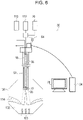
- Fig. 6 is a sectional schematic view showing a state in which the temperature of molten iron 102 inside a converter 100 is continuously measured by using in-converter temperature measurement equipment 50 according to the second embodiment.
- the in-converter temperature measurement equipment 50 according to the second embodiment has a top blowing lance 52 on whose end the lance tip 12 shown in Fig. 2 is provided, a nitrogen gas supply device 20, a switching device 54 that switches between oxygen gas and nitrogen gas, a relay unit 22, and a calculating device 24 that converts image data into temperature data.
- the lance tip 12 has a camera unit 26.
- structures that are common to those of the in-converter temperature measurement equipment 10 shown in Fig. 1 are given the same reference numerals, and descriptions that are repetitive are not given below.
- the top blowing lance 52 has a three-pipe structure. Nitrogen gas that is supplied from the nitrogen gas supply device 20 or oxygen gas that is supplied from an oxygen gas supply device 112, which is a part of converter equipment, is blown against the molten iron 102 by passing through a central pipe. Cooling water is supplied from a cooling water supply device 110, which is a part of converter equipment, and circulates by passing through two outer pipes. In Fig. 6 , reference sign 56 denotes the flow of nitrogen gas or the flow of oxygen gas. When decarburization blowing is to be performed, oxygen gas is supplied to the molten iron 102 from the top blowing lance 52. Therefore, the decarburization of carbon that is included in the molten iron 102 progresses, and the carbon concentration of the molten iron 102 is reduced.
- the nitrogen gas supply device 20 may be an argon supply device that supplies, for example, argon as an inert gas.
- the lance tip 12 shown in Fig. 2 can be used.
- the top blowing lance 52 in order to increase the area of contact of oxygen gas with a molten iron surface, it is preferable to use a lance tip having a plurality of wide peripheral holes 34, and it is more preferable to use a lance tip having four to eight peripheral holes 34. It is preferable that each peripheral hole 34 face slightly outward from the axial center of a lance tip body 30. Therefore, it is possible to suppress mutual interference between gas flows of oxygen gas from the peripheral holes 34 and to suppress scattering of the molten iron 102 caused by the merging of oxygen gas.
- the in-converter temperature measurement equipment 50 As described above, even due to the use of the in-converter temperature measurement equipment 50 according to the second embodiment, it is possible to, while observing the molten iron 102 inside the converter 100, continuously measure the temperature of the molten iron 102. Therefore, the accuracy of the blowing end temperature in the blowing step is increased, as a result of which it is possible to reduce blowing time and the amount of use of auxiliary material. Since a consumable-type probe used in a conventional sub-lance is not used, running costs for measuring temperature can also be reduced.
- the molten stainless steel to be measured is one whose temperature increased to approximately 1500°C by bottom blowing oxygen, after preliminary treatment of molten pig iron having a weight of 130 tons.
- a top blowing lance 52 having a three-pipe structure was installed so that the position of a camera unit 26 was 4.6 m from a slag surface. Nitrogen gas or oxygen gas supplied from the top blowing lance 52 was switched over by a switching device 54.
- oxygen gas was blown from a central pipe of the top blowing lance 52; when the temperature of the molten stainless steel was to be measured, nitrogen gas (flow rate 300 Nm 3 /min) was blown against the molten stainless steel; and molten iron 102 inside a converter 100 was photographed with the camera unit 26 provided at an end.
- the camera unit 26 a camera including a CMOS sensor was used. The guaranteed operation temperature of the camera used is 55°C.
- luminance data using a correspondence relationship, previously measured in a black-body furnace, between the luminance and temperature was converted into temperature data to thereby continuously measure the temperature of the liquid surface of the molten stainless steel.
- conventional batch temperature measurements using a sub-lance were also performed.
- a temperature sensor was provided inside a housing 38 of the camera unit 26, and the ambient temperature inside the housing 38 during standby above a converter and the ambient temperature inside the housing 38 while inserted inside the converter were also measured.
- Fig. 7 is a graph showing temperature measurement results of stainless molten steel obtained by the in-converter temperature measurement equipment 50.
- the horizontal axis indicates elapsed time (min), and the vertical axis indicates molten stainless steel temperature (°C).
- the black dots shown in Fig. 7 indicate pieces of temperature data measured by the batch temperature measurements, and the numerical values indicate the temperatures thereof.
- the temperatures measured by the batch temperature measurements and the temperatures measured by the in-converter temperature measurement equipment 50 were the same. From the results, it was confirmed that the temperature of the liquid surface of the molten stainless steel whose temperature was increased to approximately 1500°C by bottom blowing oxygen could be continuously measured by using the in-converter temperature measurement equipment 50.
- Fig. 8 is a graph showing ambient temperatures inside the housing.
- the horizontal axis indicates elapsed time (min:sec), and the vertical axis indicates ambient temperature (°C) inside the housing.
- min:sec elapsed time
- °C ambient temperature
Landscapes
- Engineering & Computer Science (AREA)
- Chemical & Material Sciences (AREA)
- Manufacturing & Machinery (AREA)
- Materials Engineering (AREA)
- Metallurgy (AREA)
- Organic Chemistry (AREA)
- Mechanical Engineering (AREA)
- General Engineering & Computer Science (AREA)
- Radiation Pyrometers (AREA)
- Carbon Steel Or Casting Steel Manufacturing (AREA)
Abstract
Description
- The present invention relates to a lance tip that is used in measuring the temperature of molten iron that is subjected to blowing inside a converter, in-converter temperature measurement equipment, and an in-converter temperature measurement method using the lance tip and the in-converter temperature measurement equipment.
- In, for example, a blowing process in steelmaking in a converter, a top blowing lance is used, oxygen gas is blown against molten iron to oxidize (burn) phosphorus, carbon, or the like in the molten iron and to adjust the composition of molten iron, and the temperature of molten iron is adjusted so as to become an optimal temperature in a processing operation of a next step. The measurement of the temperature of molten iron during the blowing is important not only with respect to the adjustment of temperature of molten iron but also from the viewpoint of adjusting the composition of molten iron.
- As a technology of measuring the temperature of molten iron,
Patent Literature 1 discloses a technology in which an in-converter observation probe provided with a CCD camera is provided at an end of a sub-lance, and the sub-lance is inserted into a converter to measure the temperature inside the converter. Patent Literature 2 discloses a technology in which a CCD camera is provided at an end portion opposite to an end portion of a main lance, and molten iron is photographed from an upper side of the outside of the lance through a hole for ejecting a gas, to thereby measure the temperature of molten iron. Patent Literature 3 discloses a technology in which the luminance of molten iron is measured using a CCD camera from a tuyere of a bottom portion of a converter, to thereby measure the temperature of molten iron. Further, Patent Literature 4 discloses a technology in which a single-core optical fiber that is small enough not to hinder injection of an oxygen jet is installed near an injection nozzle opening of a main lance, and a monochromatic thermometer that is connected to the single-core optical fiber is used to measure the temperature. -
- PTL 1:
Japanese Unexamined Patent Application Publication No. 10-88221 - PTL 2:
Japanese Unexamined Patent Application Publication No. 2006-126062 - PTL 3:
Japanese Unexamined Patent Application Publication No. 2007-322382 - PTL 4:
Japanese Unexamined Patent Application Publication No. 62-226025 - However, in order to increase the hitting accuracy of a blowing end temperature, it is necessary to continuously capture temperature changes in at least a few minutes in the second half of a blowing step. Since the sub-lance disclosed in
Patent Literature 1 is a device that intermittently captures the state of the inside of the converter, the temperature changes cannot be continuously captured and it is difficult to increase the hitting accuracy of the blowing end temperature. Further, since probes are worn with each measurement timing, probes need to be frequently replaced, and thus running costs are increased. - In the device disclosed in Patent Literature 2, since the camera is installed at a position separated by a distance of 10 m or greater from an object to be measured, it is difficult to know which position on a surface of molten iron inside a converter is being observed due to a reduced field of view. In the measurement method disclosed in Patent Literature 3, a high-temperature ladle that is disposed below the converter or the heat of the converter itself heats the CCD camera unit and thus damages this equipment.
- What can be obtained from the device disclosed in Patent Literature 4 is only data regarding temperature, and a temperature measurement position cannot be directly observed. Therefore, the measured temperature may be the temperature of slag instead of the temperature of molten iron, and thus the temperature of molten iron cannot be precisely measured.
- The present invention has been made in view of such problems of the related art, and an object of the present invention is to provide in-converter temperature measurement equipment that is capable of continuously measuring the temperature of molten iron inside a converter, a lance tip that is used in the in-converter temperature measurement device, and an in-converter temperature measurement method using the in-converter temperature measurement equipment and the lance tip.
- Means for solving the problems described above are as follows.
- (1) A lance tip of a lance that is inserted into a converter includes a cylindrical lance tip body and a camera unit. The lance tip body is provided with a containing portion, peripheral holes through which a gas that is blown against molten iron inside the converter pass, and a water cooling path disposed so as to surround the containing portion. The camera unit has an image sensor configured to generate image data by photographing the molten iron, a lens, and a radiant-heat shielding filter. The camera unit is provided in the containing portion.
- (2) In-converter temperature measurement equipment that measures a temperature of molten iron inside a converter includes a sub-lance on whose end the lance tip according to (1) is provided, an inert gas supply device, and a calculating device configured to convert the image data into temperature data.
- (3) In-converter temperature measurement equipment that measures a temperature of molten iron inside a converter includes a top blowing lance on whose end the lance tip according to (1) is provided, an inert gas supply device, a switching device configured to switch between oxygen gas and inert gas, and a calculating device configured to convert the image data into temperature data.
- (4) In the in-converter temperature measurement equipment according to (2) or (3), the calculating device is configured to convert spectral radiance data generated from the image data into temperature data.
- (5) The in-converter temperature measurement equipment according to any one of (2) to (4), further includes a display device configured to display the image data generated by the image sensor.
- (6) An in-converter temperature measurement method using the in-converter temperature measurement equipment according to any one of (2) to (5) includes photographing the molten iron with the camera unit while blowing inert gas against the molten iron, and converting the generated image data into temperature data.
- It is possible to, by using the in-converter temperature measurement equipment having a lance tip according to the present invention, continuously measure the temperature of molten iron inside the converter while observing the molten iron. Accordingly, it is possible to increase the hitting accuracy of a blowing end temperature in a blowing step and to, thus, reduce the blowing time and the amount of use of auxiliary material.
-
- [
Fig. 1] Fig. 1 is a sectional schematic view showing a state in which the temperature ofmolten iron 102 inside aconverter 100 is continuously measured by using in-convertertemperature measurement equipment 10 according to a first embodiment. - [
Fig. 2] Fig. 2(a) and Fig. 2(b) are a sectional view and a front view of alance tip 12, respectively. - [
Fig. 3] Fig. 3 is a perspective view showing a structure of acamera unit 26. - [
Fig. 4] Fig. 4 shows simulation results obtained by a simulation of temperature changes of animage sensor 40 and alens 42 when asub-lance 14 is inserted in theconverter 100. - [
Fig. 5] Fig. 5 is a graph showing a temperature change of molten iron during blowing whose purpose is decarburization. - [
Fig. 6] Fig. 6 is a sectional schematic view showing a state in which the temperature ofmolten iron 102 inside aconverter 100 is continuously measured by using in-convertertemperature measurement equipment 50 according to a second embodiment. - [
Fig. 7] Fig. 7 is a graph showing temperature measurement results of molten stainless steel obtained by the in-convertertemperature measurement equipment 50. - [
Fig. 8] Fig. 8 is a graph showing ambient temperatures inside a housing. -
Fig. 1 is a sectional schematic view showing a state in which the temperature ofmolten iron 102 inside aconverter 100 is continuously measured by using in-convertertemperature measurement equipment 10 according to a first embodiment. The temperature measurement of themolten iron 102 using the in-convertertemperature measurement equipment 10 according to the present embodiment can be applied to a blowing step whose purpose is, for example, desiliconization, dephosphorization, or decarburization. In the embodiment below, the in-convertertemperature measurement equipment 10 according to the first embodiment is described as being applied to a blowing step whose purpose is decarburization of molten iron. - Oxygen is supplied from a top blowing
lance 104 to themolten iron 102 contained in theconverter 100, and a bottom blowing gas, such as nitrogen, is blown from abottom blowing tuyere 106 and is mixed. Therefore, the decarburization of carbon that is included in themolten iron 102 progresses, and the carbon concentration of themolten iron 102 is reduced. In the decarburization blowing, an end point constituent concentration and a blowing end temperature of themolten iron 102 to be targeted are subjected to static control and dynamic control, and an end point constituent concentration and a blowing end temperature of themolten iron 102 after the blowing are caused to hit the target values. Here, "static control" is control that, from an operation condition before the blowing is started, calculates, for example, the oxygen content that is blown to themolten iron 102. "Dynamic control" is control that, based on a constituent concentration and a temperature measurement value of themolten iron 102 that are measured in the second half of the blowing step, adjusts, for example, the oxygen content that is blown to themolten iron 102. - The in-converter
temperature measurement equipment 10 according to the first embodiment is used in the temperature measurement of themolten iron 102 in the second half of the blowing step, used in the dynamic control. The in-convertertemperature measurement equipment 10 according to the first embodiment has asub-lance 14 on whose end alance tip 12 is provided, a nitrogengas supply device 20, arelay unit 22, and a calculatingdevice 24 that converts image data into temperature data. Thelance tip 12 has acamera unit 26. - The
sub-lance 14, which is different from the top blowinglance 104, refers to a lance that is a measuring probe which is inserted into the converter, and that includes in the inside thereof a measuring device, such as a thermocouple. Thesub-lance 14 may be provided with a gas flow path or a cooling water path as appropriate for protecting the measuring device provided inside thesub-lance 14. In the present embodiment, thesub-lance 14 has a three-pipe structure. Nitrogen gas is supplied from the nitrogengas supply device 20, and is blown against themolten iron 102 by passing through a central pipe. Cooling water is supplied from a coolingwater supply device 110, which is a part of converter equipment, and circulates by passing through two outer pipes. InFig. 1 ,reference sign 16 denotes the flow of nitrogen gas, andreference sign 18 denotes the flow of cooling water. With thesub-lance 14 inserted inside theconverter 100, thesub-lance 14, while blowing nitrogen gas against themolten iron 102, photographs themolten iron 102 inside theconverter 100 with thecamera unit 26 provided at an end of thesub-lance 14. Since dust or the like can be removed from a photographing path of thecamera unit 26 by blowing nitrogen gas against themolten iron 102 from the sub-lance 14 in this way, themolten iron 102 can be photographed without being blocked by the dust or the like. Nitrogen gas is an example of inert gas, and argon gas may be used as the inert gas. - The
camera unit 26 continuously photographs themolten iron 102, and continuously generates image data. Thecamera unit 26 may photograph a moving image of themolten iron 102. The image data generated by thecamera unit 26 is transmitted to the calculatingdevice 24 via therelay unit 22. The transmission of the image data to therelay unit 22 from thecamera unit 26 and the transmission of the image data to the calculatingdevice 24 from therelay unit 22 may be performed through wire or may be wireless. - The calculating
device 24 is, for example, a work station or a general-purpose computer, such as a personal computer. The calculatingdevice 24 converts the image data that is transmitted from thecamera unit 26 into temperature data. As a method of converting the image data into temperature data, there are a method of converting luminance data into temperature data by obtaining the luminance data from the image data and a method of converting spectral radiance data into temperature data by obtaining the spectral radiance data from the image data. - When the luminance data is converted into temperature data, from the obtained image data, the calculating
device 24 obtains, as the luminance data, for example, an integral value of luminance within a predetermined sampling time or a maximum luminance value. By using a correspondence relationship, previously measured at a blackbody furnace, between the luminance data and temperature, the calculatingdevice 24 converts the obtained luminance data into temperature data. - On the other hand, as a method of converting the spectral radiance data into temperature data, a measurement principle based on a two-color radiation thermometer (also called a two-color thermometer or a ratio thermometer) can be applied. In the two-color radiation thermometer, the radiances at two different wavelengths are measured, the ratio between the radiances is calculated, and a comparison is made with a previously measured black-body radiance ratio, to thereby convert it into the temperature of an object. This method can relatively stably measure the temperature even if a change in emissivity occurs. When the spectral radiance data is converted into temperature data based on a principle that is the same as that of the two-color radiation thermometer, the calculating
device 24 obtains, based on three primary colors, which are red (R), green (G), and blue (B), for example, R spectral radiance data and G spectral radiance data, and calculates the radiance ratio from the radiance data, the three primary colors being pieces of image data. The calculatingdevice 24 converts the spectral radiance data into temperature data by using a correspondence relationship, previously examined at, for example, a black-body radiation furnace, between the intensity ratio of the spectral radiance data and temperature. - When image data captured by an infrared camera is used, the calculating
device 24 prepares luminance data corresponding to the infrared wavelength. The calculatingdevice 24 converts the luminance data into temperature data by using a correspondence relationship, previously examined using, for example, a black-body radiation furnace, between the intensity of the luminance data and temperature. As the luminance data that is obtained from the image data, as long as the relationship between a wavelength component intensity thereof and the temperature is previously known, it is possible to use any wavelength component data in an infrared wavelength range. - When, as the
camera unit 26, a device having functions from obtaining image data to converting the image data into temperature data as is the case of an infrared thermography camera is used, the calculatingdevice 24 need not have the function of converting the image data into temperature data. The calculatingdevice 24 displays the temperature data on, for example, adisplay device 28, such as a display. In this way, the temperature of a liquid surface of themolten iron 102 is continuously measured by using the in-convertertemperature measurement equipment 10 according to the first embodiment. The calculatingdevice 24 may display on thedisplay device 28 image data that has been transmitted together with the temperature data. In this way, since, by displaying the image data on thedisplay device 28, the molten iron inside the converter can have its temperature measured while being observed, it is possible to determine whether the temperature data is the temperature of themolten iron 102 or the temperature ofslag 114 formed on a surface of themolten iron 102. In addition, by selectively using the temperature data determined as being the temperature of themolten iron 102, it is possible to prevent the measurement of the temperature of theslag 114 and to thereby increase the temperature measurement accuracy of themolten iron 102. When the image data is to be transmitted to another display device by wireless communication, the in-convertertemperature measurement equipment 10 need not have thedisplay device 28. -
Fig. 2(a) and Fig. 2(b) are a sectional view and a front view of thelance tip 12, respectively. The sectional view ofFig. 2(a) is a sectional view along A-A in the front view ofFig. 2(b) . Thelance tip 12 has a cylindrical shape having the same diameter as thesub-lance 14, and is attached to an end of thesub-lance 14. Thelance tip 12 has alance tip body 30 and thecamera unit 26. Thelance tip body 30 has, for example, a cylindrical shape having a diameter of 300 to 600 mm (400 mm in the example shown inFig. 2 ), and is provided with a containingportion 32,peripheral holes 34, and acooling water path 36. - The containing
portion 32 is a through hole provided at the axial center of thelance tip body 30 and having a diameter of 35 to 70 mm (57 mm in the example shown inFig. 2 ). Thecamera unit 26 is installed in the containingportion 32. Although the containingportion 32 may be a recessed portion that does not open into thesub-lance 14, if the containingportion 32 opens into thesub-lance 14, thecamera unit 26 is cooled by nitrogen gas and a temperature rise of thecamera unit 26 is suppressed, which is more preferable. - The
peripheral holes 34 are each a hole that passes therethrough nitrogen gas that is blown against themolten iron 102. Eachperipheral hole 34 is connected with the central pipe of thesub-lance 14. As shown inFig. 2(b) , sixperipheral holes 34 are provided side by side in a ring in an end surface of thelance tip body 30. AlthoughFig. 2 shows an example in which sixperipheral holes 34 are provided, it is not limited thereto, and at least one peripheral hole only needs to be provided. However, the number ofperipheral holes 34 is preferably 4 or more and 8 or less. When the number ofperipheral holes 34 is 4 or more and 8 or less, the surrounding of thecamera unit 26 can be uniformly cooled. In order to remove dust or theslag 114 from the photographing path, a peripheral hole facing the photographing path may be provided. - The cooling
water path 36 is a pipe that passes therethrough cooling water that is supplied from the coolingwater supply device 110. The coolingwater path 36 is provided so as to surround the containingportion 32. The coolingwater path 36 is connected with the two outer pipes on the outer side of the sub-lance 14, and cooling water circulates inside the coolingwater path 36. Thecamera unit 26 installed in the containingportion 32 is cooled due to cooling water of 40°C or lower flowing in the coolingwater path 36. Therefore, even if thecamera unit 26 is inserted into a high-temperature converter, the temperature of thecamera unit 26 can be kept less than or equal to a guaranteed operation temperature of thecamera unit 26. For thecamera unit 26, for example, a camera unit whose guaranteed operation temperature is 85°C can be used. For example, a CHEETAH series product manufactured by IMPERX applies to such a camera unit. A heat-resistant camera that can endure a temperature of even 200°C manufactured by Integrate Systems Co., Ltd. may be used. Even if a commercial camera whose guaranteed operation temperature is about 60°C is used, as long as the commercial camera is used for a short period of about a few months, the camera can sometimes endure even an ambient temperature of 85 to 100°C. Although the example shown inFig. 2 is an example in which the containingportion 32 is provided at the axial center of thelance tip body 30, it is not limited thereto. The containingportion 32 only needs to be provided in a range surrounded by the coolingwater path 36. -
Fig. 3 is a perspective view showing a structure of thecamera unit 26.Fig. 3(a) is a perspective view of thecamera unit 26, andFig. 3(b) is a perspective view showing each structure of thecamera unit 26. Thecamera unit 26 has ahousing 38, animage sensor 40, alens 42, two radiant-heat shielding filters 44, fixed rings 46, and abattery 48. Thehousing 38 is made of a metal having a high thermal conductivity, such as Cu, and is a hollow cylindrical container having a photographing hole on one end surface side. The outside diameter of thehousing 38 is the same as the inside diameter of the containingportion 32. In the example shown inFig. 2 , the inside diameter of the containingportion 32 is 57 mm. - The
image sensor 40 is a sensor that generates image data by photographing themolten iron 102. Theimage sensor 40 includes a CCD sensor and a data processing circuit that processes data generated by the CCD sensor and transforms the processed data into image data. The two radiant-heat shielding filters 44 are fixed to corresponding ones of the fixed rings 46 on a side of thelens 42 facing themolten iron 102. A temperature rise of thelens 42 and theimage sensor 40 caused by radiant heat from the molten iron is suppressed by providing the radiant-heat shielding filters 44, and, thus, damage to thelens 42 and theimage sensor 40 is suppressed. If the two radiant-heat shielding filters 44 can be fixed to thelens 42 by another means, the fixed rings 46 need not be provided. Although, as theimage sensor 40, an example in which theimage sensor 40 has a CCD sensor is described, theimage sensor 40 is not limited thereto, and a CMOS sensor may be used instead of a CCD sensor. - As the radiant-heat shielding filters 44, one or more types selected from an ND filter (model NDUV10B, model NDUV20B, model NDUV30B) manufactured by Thorlab Inc., a hot mirror (infrared cut filter) (model M254H00) manufactured by Thorlab Inc., and a bandpass filter (model FL532-1) manufactured by Thorlab Inc. can be used. Although
Fig. 3 shows an example in which two radiant-heat shielding filters 44 are provided, it is not limited thereto. As long as there is one or more radiant-heat shielding filters 44, it is possible to suppress a temperature rise of thecamera unit 26 caused by radiant heat of molten iron and to prevent damage to thecamera unit 26. When spectral radiance data is used in the calculatingdevice 24, it is preferable to use a radiant-heat shielding filter that blocks radiant heat having a wavelength different from a wavelength used for converting the spectral radiance data into temperature data. - The
image sensor 40, thelens 42, the two radiant-heat shielding filters 44, and thebattery 48 are installed inside thehousing 38, and thehousing 38 is fixed to the containingportion 32, to thereby mount thecamera unit 26 to the lance tip body. Theimage sensor 40, thelens 42, and the two radiant-heat shielding filters 44 may be directly mounted inside the containingportion 32, and, thus, thecamera unit 26 need not have a housing. However, since the workability when replacing thecamera unit 26 is better when, for example, theimage sensor 40 is previously fixed inside thehousing 38 and the housing is fixed to the containingportion 32, it is preferable that thecamera unit 26 have thehousing 38. Thebattery 48 is a device that supplies electric power that drives theimage sensor 40. As long as thecamera unit 26 and an external power source are connected to each other, thecamera unit 26 need not have thebattery 48. - Since the temperature of the inside of the converter during blowing is high, when the sub-lance 14 is inserted and the
molten iron 102 is photographed, the temperature of thecamera unit 26 becomes high, as a result of which thelens 42 and theimage sensor 40 may be damaged. Therefore, in the in-convertertemperature measurement equipment 10 according to the first embodiment, a temperature rise of theimage sensor 40 and thelens 42 is suppressed by disposing the coolingwater path 36 around the containingportion 32 to perform cooling, and by providing the radiant-heat shielding filters 44 on the side of thelens 42 facing themolten iron 102. -
Fig. 4 shows simulation results obtained by a simulation of temperature changes of theimage sensor 40 and thelens 42 when the sub-lance 14 is inserted in theconverter 100. In the simulation, temperature changes of a portion where theimage sensor 40 and thelens 42 were contained were simulated by using STAR-CCM+ (manufactured by SIEMENS) and by using cooling water temperatures, a cooling water amount, a thermal conductivity of an outer surface of the lance tip, a thermal conductivity of an inner surface of the lance tip, a lance outer surface temperature, a lance inner surface temperature, and a thermal conductivity of each radiant-heat shielding filter, all of which are shown in Table 1 below. In the simulation, the cooling effect by nitrogen gas is not considered. As a boundary condition, a heat flux from the lance outer surface inside the converter was 800 kW/m2. This value is a value that has been set on the assumption that a heat input to cooling water calculated based on an entry-side temperature value and an exit-side temperature value of the cooling water is equal to a heat input from the lance outer surface inside the converter.[Table 1] Item Unit Value Cooling Water Entry-Side Temperature ° C 27 Exit-Side Temperature °C 35 Cooling Water Amount t/h 500 Thermal Conductivity Lance-Tip Outer Surface W/(m2 × K) 47 Lance-Tip Inner Surface W/(m2 × K) 2026 Temperature Lance-Tip Outer Surface ° C 1450 Lance-Tip Inner Surface °C 30 Thermal Conductivity Radiant-Heat Shielding Filter W/(m × K) 1.5 - As shown in
Fig. 4 , the average temperature of a first radiant-heat shielding filter 44(A) became 84°C, and the maximum temperature thereof became 94°C. The average temperature of a second radiant-heat shielding filter 44(B) became 62°C, and the maximum temperature thereof became 66°C. The average temperature of the portion where theimage sensor 40 and thelens 42 were contained became 32°C, and the maximum temperature thereof became 61°C. It was confirmed that, since the guaranteed operation temperature of thecamera unit 26 used in the first embodiment was less than or equal to 100°C, as long as at least one radiant-heat shielding filter 44 was provided, the temperatures of theimage sensor 40 and thelens 42 of thecamera unit 26 could be maintained at less than 100°C. -
Fig. 5 is a graph showing a temperature change of molten iron during blowing whose purpose is decarburization. InFig. 5 , the vertical axis indicates molten iron temperature (°C), and the horizontal axis indicates carbon concentration (mass%). Since oxygen is supplied from thetop blowing lance 104 and the carbon concentration of themolten iron 102 is reduced, the carbon concentration changes from right to left along the horizontal axis as the blowing progresses. On the other hand, the temperature of themolten iron 102 rises as the blowing progresses. - In conventional blowing dynamic control, in the second half of a blowing step, the sub-lance is intermittently inserted to measure the temperature of the
molten iron 102, and a timing in which a blowing end temperature of themolten iron 102 becomes a target temperature is predicted from the measured value. However, since the timing is only a prediction, the blowing end temperature sometimes does not become the target value due to some reason. In contrast, since, by using the in-convertertemperature measurement equipment 10 according to the first embodiment, themolten iron 102 can be subjected to blowing while its temperature is continuously measured in the second half of the blowing step, the blowing end temperature and the target temperature will not differ from each other. - Although, in the example, described above, an example in which the temperature of the
molten iron 102 is measured in the second half of the blowing step has been described, the temperature of themolten iron 102 may be continuously measured in the entire blowing step by using the in-convertertemperature measurement equipment 10 according to the first embodiment. In this way, due to continuously measuring the temperature of themolten iron 102 during the blowing, even if a contingency in the blowing step, such as an abnormal temperature rise during the blowing, occurs, it is possible to quickly detect the contingency and to thus quickly deal with the contingency. In this way, by quickly dealing with the contingency, it is possible to suppress an increase in damages caused by the contingency. - As described above, due to the use of the in-converter
temperature measurement equipment 10 according to the first embodiment, it is possible to, while observing themolten iron 102 inside theconverter 100, continuously measure the molten iron. Therefore, the accuracy of the blowing end temperature in the blowing step is increased, as a result of which it is possible to reduce blowing time and the amount of use of auxiliary material. Since a consumable-type probe used in a conventional sub-lance is not used, running costs for measuring temperature can also be reduced. - Next, a second embodiment is described.
Fig. 6 is a sectional schematic view showing a state in which the temperature ofmolten iron 102 inside aconverter 100 is continuously measured by using in-convertertemperature measurement equipment 50 according to the second embodiment. The in-convertertemperature measurement equipment 50 according to the second embodiment has atop blowing lance 52 on whose end thelance tip 12 shown inFig. 2 is provided, a nitrogengas supply device 20, aswitching device 54 that switches between oxygen gas and nitrogen gas, arelay unit 22, and a calculatingdevice 24 that converts image data into temperature data. Thelance tip 12 has acamera unit 26. In the in-convertertemperature measurement equipment 50 shown inFig. 6 , structures that are common to those of the in-convertertemperature measurement equipment 10 shown inFig. 1 are given the same reference numerals, and descriptions that are repetitive are not given below. - The
top blowing lance 52 has a three-pipe structure. Nitrogen gas that is supplied from the nitrogengas supply device 20 or oxygen gas that is supplied from an oxygengas supply device 112, which is a part of converter equipment, is blown against themolten iron 102 by passing through a central pipe. Cooling water is supplied from a coolingwater supply device 110, which is a part of converter equipment, and circulates by passing through two outer pipes. InFig. 6 ,reference sign 56 denotes the flow of nitrogen gas or the flow of oxygen gas. When decarburization blowing is to be performed, oxygen gas is supplied to themolten iron 102 from thetop blowing lance 52. Therefore, the decarburization of carbon that is included in themolten iron 102 progresses, and the carbon concentration of themolten iron 102 is reduced. - On the other hand, when the temperature of the
molten iron 102 is to be measured, a gas that is transported is switched from oxygen gas to nitrogen gas by the switchingdevice 54, and, while the nitrogen gas is being blown against themolten iron 102, themolten iron 102 inside theconverter 100 is photographed by thecamera unit 26 provided at an end. In this way, the temperature of themolten iron 102 inside theconverter 100 is continuously measured by using the in-convertertemperature measurement equipment 50. The nitrogengas supply device 20 may be an argon supply device that supplies, for example, argon as an inert gas. - As the lance tip provided at an end of the
top blowing lance 52, thelance tip 12 shown inFig. 2 can be used. However, when thetop blowing lance 52 is used, in order to increase the area of contact of oxygen gas with a molten iron surface, it is preferable to use a lance tip having a plurality of wideperipheral holes 34, and it is more preferable to use a lance tip having four to eightperipheral holes 34. It is preferable that eachperipheral hole 34 face slightly outward from the axial center of alance tip body 30. Therefore, it is possible to suppress mutual interference between gas flows of oxygen gas from theperipheral holes 34 and to suppress scattering of themolten iron 102 caused by the merging of oxygen gas. - As described above, even due to the use of the in-converter
temperature measurement equipment 50 according to the second embodiment, it is possible to, while observing themolten iron 102 inside theconverter 100, continuously measure the temperature of themolten iron 102. Therefore, the accuracy of the blowing end temperature in the blowing step is increased, as a result of which it is possible to reduce blowing time and the amount of use of auxiliary material. Since a consumable-type probe used in a conventional sub-lance is not used, running costs for measuring temperature can also be reduced. - Next, an example in which the temperature of a liquid surface of molten stainless steel manufactured by smelting in a converter is continuously measured by using the in-converter
temperature measurement equipment 50 shown inFig. 6 is described. The molten stainless steel to be measured is one whose temperature increased to approximately 1500°C by bottom blowing oxygen, after preliminary treatment of molten pig iron having a weight of 130 tons. - In the present example, a
top blowing lance 52 having a three-pipe structure was installed so that the position of acamera unit 26 was 4.6 m from a slag surface. Nitrogen gas or oxygen gas supplied from thetop blowing lance 52 was switched over by aswitching device 54. When the molten stainless steel was to be subjected to blowing, oxygen gas was blown from a central pipe of thetop blowing lance 52; when the temperature of the molten stainless steel was to be measured, nitrogen gas (flow rate 300 Nm3/min) was blown against the molten stainless steel; andmolten iron 102 inside aconverter 100 was photographed with thecamera unit 26 provided at an end. As thecamera unit 26, a camera including a CMOS sensor was used. The guaranteed operation temperature of the camera used is 55°C. - With a maximum value of luminance within a sampling time of image data generated by the
camera unit 26 being defined as luminance data, the luminance data using a correspondence relationship, previously measured in a black-body furnace, between the luminance and temperature was converted into temperature data to thereby continuously measure the temperature of the liquid surface of the molten stainless steel. In order to evaluate the accuracy of temperature measurement results obtained by the present example, conventional batch temperature measurements using a sub-lance were also performed. Further, a temperature sensor was provided inside ahousing 38 of thecamera unit 26, and the ambient temperature inside thehousing 38 during standby above a converter and the ambient temperature inside thehousing 38 while inserted inside the converter were also measured. -
Fig. 7 is a graph showing temperature measurement results of stainless molten steel obtained by the in-convertertemperature measurement equipment 50. InFig. 7 , the horizontal axis indicates elapsed time (min), and the vertical axis indicates molten stainless steel temperature (°C). The black dots shown inFig. 7 indicate pieces of temperature data measured by the batch temperature measurements, and the numerical values indicate the temperatures thereof. As shown inFig. 7 , the temperatures measured by the batch temperature measurements and the temperatures measured by the in-convertertemperature measurement equipment 50 were the same. From the results, it was confirmed that the temperature of the liquid surface of the molten stainless steel whose temperature was increased to approximately 1500°C by bottom blowing oxygen could be continuously measured by using the in-convertertemperature measurement equipment 50. -
Fig. 8 is a graph showing ambient temperatures inside the housing. InFig. 8 , the horizontal axis indicates elapsed time (min:sec), and the vertical axis indicates ambient temperature (°C) inside the housing. As shown inFig. 8 , it was confirmed that the temperature inside thehousing 38 was maintained at about ordinary temperature from the time during the standby above the converter to the time while the housing was inserted inside the furnace. - It was confirmed that when, after the end of the blowing process in the converter, a
lance tip 12 was removed from thetop blowing lance 52 and thecamera unit 26 provided in the containingportion 32 was checked, thecamera unit 26 operated normally. From this result, it was confirmed that, in the in-convertertemperature measurement equipment 50 according to the present example, even if the temperature of a 1500°C molten stainless steel was measured, theimage sensor 40 and thelens 42 could be kept at approximately ordinary temperature, and damage to thecamera unit 26 due to heating of the molten stainless steel could be prevented. -
- 10
- in-converter temperature measurement equipment
- 12
- lance tip
- 14
- sub-lance
- 16
- flow of nitrogen gas
- 18
- flow of cooling water
- 20
- nitrogen gas supply device
- 22
- relay unit
- 24
- calculating device
- 26
- camera unit
- 28
- display device
- 30
- lance tip body
- 32
- containing portion
- 34
- peripheral hole
- 36
- cooling water path
- 38
- housing
- 40
- image sensor
- 42
- lens
- 44
- radiant-heat shielding filter
- 46
- fixed ring
- 48
- battery
- 50
- in-converter temperature measurement equipment
- 52
- top blowing lance
- 54
- switching device
- 56
- flow of nitrogen gas or flow of oxygen gas
- 100
- converter
- 102
- molten iron
- 104
- top blowing lance
- 106
- bottom blowing tuyere
- 110
- cooling water supply device
- 112
- oxygen gas supply device
- 114
- slag
Claims (6)
- A lance tip of a lance that is inserted into a converter, the lance tip comprising:a cylindrical lance tip body and a camera unit,wherein the lance tip body is provided with a containing portion, peripheral holes through which a gas that is blown against molten iron inside the converter passes, and a water cooling path disposed so as to surround the containing portion,wherein the camera unit has an image sensor configured to generate image data by photographing the molten iron, a lens, and a radiant-heat shielding filter, andwherein the camera unit is provided in the containing portion.
- In-converter temperature measurement equipment that measures a temperature of molten iron inside a converter, the in-converter temperature measurement equipment comprising:a sub-lance on whose end the lance tip according to Claim 1 is provided;an inert gas supply device; anda calculating device configured to convert the image data into temperature data.
- In-converter temperature measurement equipment that measures a temperature of molten iron inside a converter, the in-converter temperature measurement equipment comprising:a top blowing lance on whose end the lance tip according to Claim 1 is provided;an inert gas supply device;a switching device configured to switch between oxygen gas and inert gas; anda calculating device configured to convert the image data into temperature data.
- The in-converter temperature measurement equipment according to Claim 2 or Claim 3, wherein the calculating device is configured to convert spectral radiance data generated from the image data into temperature data.
- The in-converter temperature measurement equipment according to any one of Claims 2 to 4, wherein the in-converter temperature measurement equipment further comprises a display device configured to display the image data generated by the image sensor.
- An in-converter temperature measurement method using the in-converter temperature measurement equipment according to any one of Claims 2 to 5, the in-converter temperature measurement method comprising:
photographing the molten iron with the camera unit while blowing inert gas against the molten iron, and converting the generated image data that has been generated into temperature data.
Applications Claiming Priority (2)
| Application Number | Priority Date | Filing Date | Title |
|---|---|---|---|
| JP2020008408 | 2020-01-22 | ||
| PCT/JP2021/000183 WO2021149490A1 (en) | 2020-01-22 | 2021-01-06 | Lance tip, converter internal temperature measuring equipment, and converter internal temperature measuring method |
Publications (2)
| Publication Number | Publication Date |
|---|---|
| EP4047103A1 true EP4047103A1 (en) | 2022-08-24 |
| EP4047103A4 EP4047103A4 (en) | 2022-12-21 |
Family
ID=76753056
Family Applications (1)
| Application Number | Title | Priority Date | Filing Date |
|---|---|---|---|
| EP21745097.2A Pending EP4047103A4 (en) | 2020-01-22 | 2021-01-06 | Lance tip, converter internal temperature measuring equipment, and converter internal temperature measuring method |
Country Status (4)
| Country | Link |
|---|---|
| EP (1) | EP4047103A4 (en) |
| JP (1) | JP6901059B1 (en) |
| KR (2) | KR20250004382A (en) |
| CN (1) | CN114829634A (en) |
Families Citing this family (2)
| Publication number | Priority date | Publication date | Assignee | Title |
|---|---|---|---|---|
| CN115518788B (en) * | 2022-10-20 | 2025-11-18 | 上海务宝机电科技有限公司 | A catalyst injection system for CCM membrane fabrication |
| JP7782510B2 (en) * | 2023-05-12 | 2025-12-09 | Jfeスチール株式会社 | Lance tip, refining device, and method of operating a furnace equipped with the same |
Family Cites Families (15)
| Publication number | Priority date | Publication date | Assignee | Title |
|---|---|---|---|---|
| JPS5868945U (en) * | 1981-11-02 | 1983-05-11 | 品川白煉瓦株式会社 | Automatic hot spray nozzle device for pig iron mixer cars |
| JPS62226025A (en) | 1986-03-28 | 1987-10-05 | Sumitomo Metal Ind Ltd | Measuring method for fire point temperature of steel making furnace |
| JPS63317614A (en) * | 1987-06-19 | 1988-12-26 | Kobe Steel Ltd | Bending detector for holder of lance for measurement |
| JPH1088221A (en) | 1996-09-06 | 1998-04-07 | Nkk Corp | Probe for metallurgical furnace observation and method for metallurgical furnace observation |
| US6599464B1 (en) * | 1999-10-06 | 2003-07-29 | Bernd Feldhaus | Steelmaking lance with integral temperature probe |
| JP4750961B2 (en) * | 2001-03-29 | 2011-08-17 | 新日本製鐵株式会社 | Coke oven inside observation device |
| JP4260673B2 (en) * | 2004-04-30 | 2009-04-30 | Jfeスチール株式会社 | Hot spot radiation measuring method and apparatus |
| JP2006126062A (en) | 2004-10-29 | 2006-05-18 | Jfe Steel Kk | Method and apparatus for measuring temperature of molten metal |
| JP2007322382A (en) | 2006-06-05 | 2007-12-13 | Nippon Steel Corp | Temperature measurement method for molten steel in converter |
| CN101638711B (en) * | 2008-07-30 | 2011-07-20 | 天津三泰晟驰科技股份有限公司 | Photographic device inside attachment-type refining furnace |
| CN202465764U (en) * | 2012-03-06 | 2012-10-03 | 吕良玮 | Oxygen gun with light transmitting device |
| CN202643731U (en) * | 2012-04-24 | 2013-01-02 | 李宏亮 | Oxygen lance with image collection device |
| JP2015067875A (en) * | 2013-09-30 | 2015-04-13 | スチールプランテック株式会社 | Lance equipment, refining furnace using the same, and lance positioning method |
| US10400293B2 (en) * | 2014-03-14 | 2019-09-03 | Berry Metal Company | Metal making lance with infrared camera in lance head |
| CN110628983A (en) * | 2019-10-10 | 2019-12-31 | 北京科技大学 | Oxygen lance system and monitoring method for continuous monitoring of temperature in fire point zone of converter smelting |
-
2021
- 2021-01-06 KR KR1020247041007A patent/KR20250004382A/en active Pending
- 2021-01-06 JP JP2021517488A patent/JP6901059B1/en active Active
- 2021-01-06 EP EP21745097.2A patent/EP4047103A4/en active Pending
- 2021-01-06 CN CN202180007193.1A patent/CN114829634A/en active Pending
- 2021-01-06 KR KR1020227019558A patent/KR20220093224A/en not_active Ceased
Also Published As
| Publication number | Publication date |
|---|---|
| EP4047103A4 (en) | 2022-12-21 |
| CN114829634A (en) | 2022-07-29 |
| JP6901059B1 (en) | 2021-07-14 |
| KR20250004382A (en) | 2025-01-07 |
| JPWO2021149490A1 (en) | 2021-07-29 |
| KR20220093224A (en) | 2022-07-05 |
Similar Documents
| Publication | Publication Date | Title |
|---|---|---|
| KR101216657B1 (en) | Method of determining temperature of molten pig iron and method of operating blast furnace using same | |
| TW562866B (en) | Temperature measuring apparatus and method for molten metal | |
| EP4047103A1 (en) | Lance tip, converter internal temperature measuring equipment, and converter internal temperature measuring method | |
| WO2021149490A1 (en) | Lance tip, converter internal temperature measuring equipment, and converter internal temperature measuring method | |
| JP2003526005A (en) | Inserting the camera into the furnace | |
| KR102815953B1 (en) | Method of operating a furnace and a furnace training control system | |
| JP4700730B2 (en) | Apparatus for continuous temperature measurement of molten steel in tundish using optical fiber and infrared pyrometer | |
| RU2090814C1 (en) | Method of restoration of damaged refractory lining of furnace and device for realization of this method (versions) | |
| CN108168708A (en) | A kind of steel-making tundish temperature tube, temperature-measuring gun and thermometric robot and its temp measuring method | |
| CN106967862A (en) | Liquid steel temperature determines device | |
| RU2238529C1 (en) | Method of contactless measuring of surface temperature | |
| Viale et al. | Application of on-line infrared thermography in steel making industry | |
| JP7782510B2 (en) | Lance tip, refining device, and method of operating a furnace equipped with the same | |
| Rangavittal et al. | Development and testing of operator vision assistance system for foundry applications | |
| US20240377137A1 (en) | Systems and methods to evaluate spray cooling coverage of graphite furnace electrodes | |
| TWI789807B (en) | Converter blowing control method and converter blowing control system | |
| KR102485010B1 (en) | Apparatus for measuring retained slag in furnace | |
| TWI697561B (en) | Method for evaluating melting loss of bottom blowing hole of converter | |
| Iuchi et al. | Thermometry in steel production | |
| UA49344C2 (en) | A method of a heating station burning through determination | |
| JP2003294534A (en) | Temperature measuring device for molten metal | |
| Ren et al. | Experimental Research of Continuous Temperature Measurement for Molten Metal Bath through Bottom‐Blowing Component | |
| JPS62263913A (en) | Detection of outflow of converter slag | |
| Plessers | Temperature Measurements | |
| CN119043496A (en) | Molten steel online temperature measuring device and method for intermediate frequency furnace |
Legal Events
| Date | Code | Title | Description |
|---|---|---|---|
| STAA | Information on the status of an ep patent application or granted ep patent |
Free format text: STATUS: THE INTERNATIONAL PUBLICATION HAS BEEN MADE |
|
| PUAI | Public reference made under article 153(3) epc to a published international application that has entered the european phase |
Free format text: ORIGINAL CODE: 0009012 |
|
| STAA | Information on the status of an ep patent application or granted ep patent |
Free format text: STATUS: REQUEST FOR EXAMINATION WAS MADE |
|
| 17P | Request for examination filed |
Effective date: 20220518 |
|
| AK | Designated contracting states |
Kind code of ref document: A1 Designated state(s): AL AT BE BG CH CY CZ DE DK EE ES FI FR GB GR HR HU IE IS IT LI LT LU LV MC MK MT NL NO PL PT RO RS SE SI SK SM TR |
|
| RIN1 | Information on inventor provided before grant (corrected) |
Inventor name: YAKABE, MASATSUGU Inventor name: TOMITA, MASATO |
|
| A4 | Supplementary search report drawn up and despatched |
Effective date: 20221117 |
|
| RIC1 | Information provided on ipc code assigned before grant |
Ipc: F27D 3/16 20060101ALI20221111BHEP Ipc: C21C 5/46 20060101AFI20221111BHEP |
|
| DAV | Request for validation of the european patent (deleted) | ||
| DAX | Request for extension of the european patent (deleted) |