EP4046734A1 - Multi-wire frame for cutting blocks of stone material in slabs - Google Patents
Multi-wire frame for cutting blocks of stone material in slabs Download PDFInfo
- Publication number
- EP4046734A1 EP4046734A1 EP22167913.7A EP22167913A EP4046734A1 EP 4046734 A1 EP4046734 A1 EP 4046734A1 EP 22167913 A EP22167913 A EP 22167913A EP 4046734 A1 EP4046734 A1 EP 4046734A1
- Authority
- EP
- European Patent Office
- Prior art keywords
- wire
- wire frame
- groove
- designed
- guiding
- Prior art date
- Legal status (The legal status is an assumption and is not a legal conclusion. Google has not performed a legal analysis and makes no representation as to the accuracy of the status listed.)
- Granted
Links
Images



Classifications
-
- B—PERFORMING OPERATIONS; TRANSPORTING
- B23—MACHINE TOOLS; METAL-WORKING NOT OTHERWISE PROVIDED FOR
- B23D—PLANING; SLOTTING; SHEARING; BROACHING; SAWING; FILING; SCRAPING; LIKE OPERATIONS FOR WORKING METAL BY REMOVING MATERIAL, NOT OTHERWISE PROVIDED FOR
- B23D57/00—Sawing machines or sawing devices not covered by one of the preceding groups B23D45/00 - B23D55/00
- B23D57/003—Sawing machines or sawing devices working with saw wires, characterised only by constructional features of particular parts
- B23D57/0053—Sawing machines or sawing devices working with saw wires, characterised only by constructional features of particular parts of drives for saw wires; of wheel mountings; of wheels
-
- B—PERFORMING OPERATIONS; TRANSPORTING
- B28—WORKING CEMENT, CLAY, OR STONE
- B28D—WORKING STONE OR STONE-LIKE MATERIALS
- B28D1/00—Working stone or stone-like materials, e.g. brick, concrete or glass, not provided for elsewhere; Machines, devices, tools therefor
- B28D1/22—Working stone or stone-like materials, e.g. brick, concrete or glass, not provided for elsewhere; Machines, devices, tools therefor by cutting, e.g. incising
-
- B—PERFORMING OPERATIONS; TRANSPORTING
- B23—MACHINE TOOLS; METAL-WORKING NOT OTHERWISE PROVIDED FOR
- B23D—PLANING; SLOTTING; SHEARING; BROACHING; SAWING; FILING; SCRAPING; LIKE OPERATIONS FOR WORKING METAL BY REMOVING MATERIAL, NOT OTHERWISE PROVIDED FOR
- B23D57/00—Sawing machines or sawing devices not covered by one of the preceding groups B23D45/00 - B23D55/00
- B23D57/0007—Sawing machines or sawing devices not covered by one of the preceding groups B23D45/00 - B23D55/00 using saw wires
- B23D57/0023—Sawing machines or sawing devices not covered by one of the preceding groups B23D45/00 - B23D55/00 using saw wires with a plurality of saw wires or saw wires having plural cutting zones
-
- B—PERFORMING OPERATIONS; TRANSPORTING
- B23—MACHINE TOOLS; METAL-WORKING NOT OTHERWISE PROVIDED FOR
- B23D—PLANING; SLOTTING; SHEARING; BROACHING; SAWING; FILING; SCRAPING; LIKE OPERATIONS FOR WORKING METAL BY REMOVING MATERIAL, NOT OTHERWISE PROVIDED FOR
- B23D57/00—Sawing machines or sawing devices not covered by one of the preceding groups B23D45/00 - B23D55/00
- B23D57/003—Sawing machines or sawing devices working with saw wires, characterised only by constructional features of particular parts
- B23D57/0061—Sawing machines or sawing devices working with saw wires, characterised only by constructional features of particular parts of devices for guiding or feeding saw wires
-
- B—PERFORMING OPERATIONS; TRANSPORTING
- B28—WORKING CEMENT, CLAY, OR STONE
- B28D—WORKING STONE OR STONE-LIKE MATERIALS
- B28D1/00—Working stone or stone-like materials, e.g. brick, concrete or glass, not provided for elsewhere; Machines, devices, tools therefor
- B28D1/02—Working stone or stone-like materials, e.g. brick, concrete or glass, not provided for elsewhere; Machines, devices, tools therefor by sawing
- B28D1/08—Working stone or stone-like materials, e.g. brick, concrete or glass, not provided for elsewhere; Machines, devices, tools therefor by sawing with saw-blades of endless cutter-type, e.g. chain saws, i.e. saw chains, strap saws
-
- B—PERFORMING OPERATIONS; TRANSPORTING
- B28—WORKING CEMENT, CLAY, OR STONE
- B28D—WORKING STONE OR STONE-LIKE MATERIALS
- B28D7/00—Accessories specially adapted for use with machines or devices of the preceding groups
Definitions
- the present invention relates to a multi-wire frame for cutting blocks of stone material into slabs.
- multi-wire frame for cutting blocks of stone material comprising multi-pulley rollers or multi-groove drums, inside the grooves of which diamond wires for cutting blocks of stone material into slabs slide.
- the machine also has two multi-groove wire-guiding rollers or cylinders, each positioned in the vicinity of a multi-groove drum along the wire section which during machining is situated between the block to be cut and said multi-groove drum.
- the distance between the multi-groove wire-guiding drums is slightly greater than the maximum length of the blocks which can be sawn with the machine.
- the function of the wire-guiding rollers is that of keeping in alignment, parallel to each other, the diamond wires in the cutting zone, reacting to any transverse forces which tend to deviate the wires and preventing them from being displaced from the ideal trajectory; therefore the free section between the two wire-guiding rollers is only a few centimetres longer than the length of the block. Too large a distance between the wire-guiding rollers would affect the correct alignment of the wires during sawing of the blocks.
- the multi-wire frames may also have other configurations, for example three small-size multi-groove drums may be envisaged, one drum located at the top vertex having not only a transmission function but also a wire-tensioning function so that the movement path of the wires preferably has a triangular configuration.
- the diamond wires are properly guided and during their cutting operation they maintain their straight position and consequently the cut is very precise.
- the blocks have a length substantially smaller than the distance between the wire-guiding rollers, the latter will be located at a certain distance from the block to be cut so that there will be a section of diamond wire, of not insignificant length, situated between the wire-guiding rollers and the block.
- the wires will not be adequately guided and will have difficulty maintaining their straight position and, on the contrary, they may easily be displaced from their ideal arrangement. The cuts will therefore be much less precise compared to the situation previously described.
- One possible way of overcoming this drawback is to have two or more different-size machines each suitable for cutting a given range of lengths of the blocks, so as to be able to perform more precise cuts.
- the object of the invention is therefore to solve the problems of the prior art.
- a first task of the present invention is to provide a multi-wire frame in which it possible to cut blocks of stone material of different sizes, performing cuts which are always very precise, even in the case of blocks with different lengths.
- a further task of the present invention is to provide a multi-wire frame which is able to be adapted in a preferably automatic and motorized manner to the length of the block to be cut.
- the idea which has occurred is that of providing a multi-wire frame for cutting blocks of stone material, comprising two columns each provided with a slide designed to move along the respective column. Each slide is provided with at least one multi-groove drum designed to engage with a plurality of cutting wires between the two slides.
- the multi-wire frame is provided with two wire-guiding rollers which are designed to guide the wires along the cutting section.
- the frame is characterized in that it comprises motor-driven means for adjusting the distance between the wire-guiding rollers.
- one or both the wire-guiding rollers are movable in the longitudinal direction so that the distance between them may be adjusted.
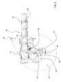
- Figures 1 and 2 show a multi-wire frame according to the present invention denoted generally by the reference number 12.
- the multi-wire frame 12 for cutting blocks of stone material comprises two columns 14, 16 each of which is provided with a slide 18, 20 designed to move along the respective column 14, 16.
- an upper cross-member 32 may be provided between the two columns 14, 16 so as to connect together the two top ends of the columns 14, 16 and reinforce the structure of the frame.
- the slides 18, 20 may be of the type known per se to person skilled in the art and are equipped with at least one multi-groove drum 22, 24, one of which is motor-driven, while the other ones are idle transmission drums.
- a multi-groove drum 22, 24 is understood as meaning also a multi-pulley roller, for the sake of easier reference.
- the multi-groove drums 22, 24 are designed to engage with a plurality of cutting wires which extend relative to each other, over a plurality of grooves in a manner known per se to the person skilled in the art, and which therefore will not further described.
- multi-groove drums are shown in schematic form, with the first groove and last groove.
- the multi-groove drums 22, 24 are two in number, each provided on one of the slides 18, 20.
- a pulley 34 is provided, said pulley not only having a transmission function, but also tensioning each diamond wire, thus creating a preferably substantially triangular movement path.
- the tensioning pulley 34 may be arranged on a cross-member 36 which joins together the two slides 18, 20.
- the multi-groove drums may be four in number.
- each slide 18, 20 may be provided with two multi-groove drums so that the four multi-groove rollers are positioned at the corners of a rectangle, this forming a preferably substantially rectangular movement path.
- the cutting section 36 is the section lying between the two multi-groove drums 22, 24 which during operation exerts the cutting action on the block of stone material.
- Wire-guiding rollers 26, 28 are provided in the vicinity of each multi-grove drum 22, 24, along the cutting section 36, said rollers being designed to guide the wires along the cutting section and withstand any horizontal/transverse forces which tend cause deviation of the cut from the ideal vertical path.
- the wire-guiding rollers 26, 28 are provided with a series of grooves positioned so as to be able to seat the diamond wires.
- the positioning of the diamond wires may be varied depending on the desired thickness of the slabs to be cut, normally about one centimetre at a time starting from a minimum thickness of about 2 centimetres.
- they may have the same length as the multi-wire drums 22, 24 so that their grooves correspond.
- the multi-wire frame according to the present invention is characterized in that it comprises movement means 30 for adjusting the distance between the wire-guiding rollers 26, 28.
- the movement means 30 for adjusting the mutual distance between the wire-guiding rollers 26, 28 comprise a mechanism 30 of the motor-driven type which allows the movement of at least one wire-guiding roller 26, 28 towards or away from the respective multi-groove drum 22, 24.
- a wire-guiding roller 26, 28 may be provided with a mechanism 30 which allows the movement of a single wire-guiding roller 26, 28 towards or away from the multi-groove drum 22, 24.
- both the wire-guiding rollers 26, 28 may be provided with a mechanism 30 which allows the movement of the wire-guiding roller 26, 28 towards or away from the respective multi-groove drum 22, 24.
- the movement of the wire-guiding roller 26, 28 occurs along a direction inclined downwards.
- Each mechanism 30 may comprise a support structure 40.
- the support structure 40 may be fixed to the slide 18, 20 or may be independent of the slide 18, 20.
- the support structure 40 may be arranged slidingly on the respective column 14, 16 and be independent of the slide 18, 20.
- the support structure 40 houses two bars 42 (in Figures 3 and 4 only one bar can be seen) located on the two opposite sides of the wire-guiding roller 26, 28.
- the two bars 42 may have a circular cross-section.
- the two bars slide, by means of bushes or bearings 44, inside corresponding cylindrical seats 46 provided in the support structure 40 and, at their ends, support the wire-guide roller 26, 28.
- the two bars 42 may be arranged horizontally, i.e. in the longitudinal direction.
- the term "longitudinal” is understood as meaning a direction parallel to the plane which contains the direction of the two columns, and substantially perpendicular to the direction of movement of the slides on the columns.
- the two bars 42 may be inclined a few degrees downwards so that, when the bars 42 are extracted, the angle of tangency of the wire with the wire-guiding roller remains constant and thus the winding arc also remains constant.
- the bars may be provided with a rack 48.
- the rack 48 may be arranged directed downwards.
- each bar may be provided with a seat for a rack which may be removable, for example by means of screws, or fixed in a non-removable manner.
- the rack is designed to mesh with a pinion 50 operated by a gear motor 52; it should also be noted that the rack 48 may also act as an anti-rotation element for the bar.
- the gear motor 52 is arranged on the support structure 40, as in the embodiments shown in the accompanying figures.
- the gear motor 52 may be arranged on a structure independent of the slide and designed to be displaced along the column.
- the gear motors 52 may be two in number for each wire-guiding roller 26, 28, each of them with its own pinion 50 acting on a respective rack 48.
- the gear motors 52 of each wire-guiding roller 26, 28 are operated in synchronism so that the axis of the wire-guiding roller during the displacement always remains parallel to itself.
- a support bracket 54 for the wire-guiding roller 26, 28 may be mounted at the free end of each bar 42.
- two supports 56 may be mounted at the bottom end of the bracket 54, preferably in an pivoting manner about a vertical axis, said supports each having a cylindrical seat 58 inside which the two ends of the spindle 60 which rotatably supports the wire-guiding roller 26, 28 are inserted.
- the pivoting support may be provided with pins 62, 64 in the vertical direction, designed to be engaged with respective seats 66, 68 formed on the bottom end of the bracket 54 and corresponding seats formed on the support 56, as shown in Figure 3 .
- each of the two ends of the spindle about which the wire-guiding roller rotates is inserted in a pivoting support. It is preferable for the support to be pivoting since, owing to the intrinsic elasticity of the system, the movement of the wire-guiding rollers might not be perfectly synchronous and therefore there is the possibility that a bar may project more than the other bar, preventing or hindering the movement of the wire-guiding rollers. Therefore, in order to avoid problems arising from imperfect synchronism, the end pins of each roller are able to pivot about a substantially vertical axis and a substantially horizontal axis.
- the frame In the first condition the frame is able to cut blocks with the maximum permitted size (length), while in the second position the frame is able to cut blocks with the minimum permitted size (length).
- the block of stone material which must be cut is positioned in the centre of the multi-wire frame, and both the wire-guiding rollers are both operated in a symmetrical manner such as to move closer together or away from each other.
- the two wire-guiding rollers are moved depending on the length and position of the block to be cut and, in particular, are moved so as to be positioned as close as possible to the block. It is possible to provide automated systems equipped with detection means, for example detectors/transducers (encoders) of the type known per se to the person skilled in the art and designed to detect the length and position of the block, and a control unit integrated in the machine and designed to set automatically the distance of the wire-guiding rollers from the block to be cut.
- detection means for example detectors/transducers (encoders) of the type known per se to the person skilled in the art and designed to detect the length and position of the block
- a control unit integrated in the machine and designed to set automatically the distance of the wire-guiding rollers from the block to be cut.
Landscapes
- Engineering & Computer Science (AREA)
- Mechanical Engineering (AREA)
- Mining & Mineral Resources (AREA)
- Processing Of Stones Or Stones Resemblance Materials (AREA)
Abstract
Description
- The present invention relates to a multi-wire frame for cutting blocks of stone material into slabs.
- In the prior art many types of multi-wire frame for cutting blocks of stone material are known, said frames comprising multi-pulley rollers or multi-groove drums, inside the grooves of which diamond wires for cutting blocks of stone material into slabs slide.
- In the present description reference will be made explicitly to multi-groove drums, it being understood that the principles of the present invention may be applied equally well also to a multi-wire frame with multi-pulley rollers, as will become clear from the continuation of the present description.
- An example of a multi-wire frame is illustrated in
Italian patent application TV2006A000060 - The machine also has two multi-groove wire-guiding rollers or cylinders, each positioned in the vicinity of a multi-groove drum along the wire section which during machining is situated between the block to be cut and said multi-groove drum. The distance between the multi-groove wire-guiding drums is slightly greater than the maximum length of the blocks which can be sawn with the machine. The function of the wire-guiding rollers is that of keeping in alignment, parallel to each other, the diamond wires in the cutting zone, reacting to any transverse forces which tend to deviate the wires and preventing them from being displaced from the ideal trajectory; therefore the free section between the two wire-guiding rollers is only a few centimetres longer than the length of the block. Too large a distance between the wire-guiding rollers would affect the correct alignment of the wires during sawing of the blocks.
- The multi-wire frames may also have other configurations, for example three small-size multi-groove drums may be envisaged, one drum located at the top vertex having not only a transmission function but also a wire-tensioning function so that the movement path of the wires preferably has a triangular configuration. There also exist frames with four small-size multi-groove drums located at the four corners of a rectangle, thus forming preferably a substantially rectangular movement path of the wires.
- The machines of the prior art, although recognized as being valid, have a number of drawbacks and therefore do not always fully satisfy the user.
- For example they have major limitations when it comes to cutting blocks of stone material with different dimensions.
- As mentioned further above, if the distance between the wire-guiding rollers is slightly greater than the length of the block to be cut, the diamond wires are properly guided and during their cutting operation they maintain their straight position and consequently the cut is very precise.
- If, however, the blocks have a length substantially smaller than the distance between the wire-guiding rollers, the latter will be located at a certain distance from the block to be cut so that there will be a section of diamond wire, of not insignificant length, situated between the wire-guiding rollers and the block. Along this path section, the wires will not be adequately guided and will have difficulty maintaining their straight position and, on the contrary, they may easily be displaced from their ideal arrangement. The cuts will therefore be much less precise compared to the situation previously described.
- Therefore, in the case where blocks of varying length must be cut, not all the cuts will be performed in a precise manner. In particular, if blocks which have a length substantially smaller than the distance between the two wire-guiding rollers must be cut, the cuts will not be very precise.
- One possible way of overcoming this drawback is to have two or more different-size machines each suitable for cutting a given range of lengths of the blocks, so as to be able to perform more precise cuts.
- Obviously this solution is somewhat costly and requires a very large (open or closed) space able to accommodate several machines. Moreover, routine and extraordinary maintenance of the set of machines would become an extremely expensive item for the business activity concerned.
- It is also evident that not even by providing several machines is it possible to have always the ideal distance between the wire-guiding rollers when there is a variation in the length of the blocks being machined.
- It is for this reason that usually the most convenient solution is that of using a single cutting machine, accepting the fact that the cuts will not always be precise in the case where blocks which have a size substantially smaller than the distance between the two wire-guiding rollers must be cut.
- The object of the invention is therefore to solve the problems of the prior art.
- A first task of the present invention is to provide a multi-wire frame in which it possible to cut blocks of stone material of different sizes, performing cuts which are always very precise, even in the case of blocks with different lengths.
- A further task of the present invention is to provide a multi-wire frame which is able to be adapted in a preferably automatic and motorized manner to the length of the block to be cut.
- The object and tasks are achieved with a multi-wire frame for cutting blocks of stone material according to the accompanying claims.
- In particular, the idea which has occurred is that of providing a multi-wire frame for cutting blocks of stone material, comprising two columns each provided with a slide designed to move along the respective column. Each slide is provided with at least one multi-groove drum designed to engage with a plurality of cutting wires between the two slides. The multi-wire frame is provided with two wire-guiding rollers which are designed to guide the wires along the cutting section. The frame is characterized in that it comprises motor-driven means for adjusting the distance between the wire-guiding rollers.
- Advantageously, one or both the wire-guiding rollers are movable in the longitudinal direction so that the distance between them may be adjusted.
- The characteristic features and advantages of a multi-wire frame according to the present invention will become clear from the description below of possible embodiments, provided solely by way of a non-limiting explanation, with reference to the accompanying drawings, in which:
-
Fig. 1 shows a schematic perspective view of a multi-wire frame according to the present invention; -
Fig. 2 shows a front schematic view of the multi-wire frame according to Claim 1; -
Figs. 3 and4 show in schematic form a part of a multi-wire frame according to the present invention. -
Figures 1 and2 show a multi-wire frame according to the present invention denoted generally by thereference number 12. - The
multi-wire frame 12 for cutting blocks of stone material comprises twocolumns slide respective column - In accordance with a possible embodiment of the present invention, an
upper cross-member 32 may be provided between the twocolumns columns - The
slides multi-groove drum - As mentioned above, in this description, a
multi-groove drum - The
multi-groove drums - For easier reference, in the accompanying figures the multi-groove drums are shown in schematic form, with the first groove and last groove.
- In accordance with a first embodiment of the present invention (not shown in the accompanying drawings), the
multi-groove drums slides pulley 34 is provided, said pulley not only having a transmission function, but also tensioning each diamond wire, thus creating a preferably substantially triangular movement path. Thetensioning pulley 34 may be arranged on across-member 36 which joins together the twoslides - In accordance with a further embodiment of the present invention (not shown in the accompanying drawings), the multi-groove drums may be four in number. Advantageously, each
slide - Although the cutting wire in the operating condition is moving, from the arrangement of the
multi-groove drums cutting section 36. The cutting section, as can be clearly seen inFigure 2 , is the section lying between the twomulti-groove drums - Wire-guiding
rollers multi-grove drum cutting section 36, said rollers being designed to guide the wires along the cutting section and withstand any horizontal/transverse forces which tend cause deviation of the cut from the ideal vertical path. The wire-guidingrollers multi-wire drums - The multi-wire frame according to the present invention is characterized in that it comprises movement means 30 for adjusting the distance between the wire-guiding
rollers - Advantageously the movement means 30 for adjusting the mutual distance between the wire-guiding
rollers mechanism 30 of the motor-driven type which allows the movement of at least one wire-guidingroller multi-groove drum - In accordance with a first embodiment of the present invention, a wire-guiding
roller mechanism 30 which allows the movement of a single wire-guidingroller multi-groove drum - In accordance with an alternative embodiment of the present invention, both the wire-guiding
rollers mechanism 30 which allows the movement of the wire-guidingroller multi-groove drum - Advantageously the movement of the wire-guiding
roller - With reference to
Figures 3 and4 , a possible embodiment of themechanism 30 which allows the movement of the wire-guidingroller multi-groove drum - Each
mechanism 30 may comprise asupport structure 40. Thesupport structure 40 may be fixed to theslide slide support structure 40 may be arranged slidingly on therespective column slide - In accordance with a possible embodiment of the present invention, the
support structure 40 houses two bars 42 (inFigures 3 and4 only one bar can be seen) located on the two opposite sides of the wire-guidingroller bars 42 may have a circular cross-section. Advantageously, the two bars slide, by means of bushes orbearings 44, inside correspondingcylindrical seats 46 provided in thesupport structure 40 and, at their ends, support the wire-guide roller - The two
bars 42 may be arranged horizontally, i.e. in the longitudinal direction. - In this description, the term "longitudinal" is understood as meaning a direction parallel to the plane which contains the direction of the two columns, and substantially perpendicular to the direction of movement of the slides on the columns.
- Advantageously, the two
bars 42 may be inclined a few degrees downwards so that, when thebars 42 are extracted, the angle of tangency of the wire with the wire-guiding roller remains constant and thus the winding arc also remains constant. - The bars may be provided with a
rack 48. Therack 48 may be arranged directed downwards. In accordance with a possible embodiment of the present invention, each bar may be provided with a seat for a rack which may be removable, for example by means of screws, or fixed in a non-removable manner. - The rack is designed to mesh with a
pinion 50 operated by agear motor 52; it should also be noted that therack 48 may also act as an anti-rotation element for the bar. - In accordance with a first embodiment of the present invention, the
gear motor 52 is arranged on thesupport structure 40, as in the embodiments shown in the accompanying figures. - In accordance with an alternative embodiment of the present invention, the
gear motor 52 may be arranged on a structure independent of the slide and designed to be displaced along the column. - Advantageously, the
gear motors 52 may be two in number for each wire-guidingroller own pinion 50 acting on arespective rack 48. Thegear motors 52 of each wire-guidingroller - In accordance with the embodiment in which both the wire-guiding
rollers gear motors 52 are designed to be operated in pairs in synchronism. - When the gear motors are operated, the associated pinions rotate and move the respective racks and therefore the bars in one direction or the other.
- A
support bracket 54 for the wire-guidingroller bar 42. - In accordance with a possible embodiment of the present invention, two
supports 56 may be mounted at the bottom end of thebracket 54, preferably in an pivoting manner about a vertical axis, said supports each having acylindrical seat 58 inside which the two ends of thespindle 60 which rotatably supports the wire-guidingroller - In accordance with a possible embodiment of the present invention the pivoting support may be provided with
pins respective seats bracket 54 and corresponding seats formed on thesupport 56, as shown inFigure 3 . - Each of the two ends of the spindle about which the wire-guiding roller rotates is inserted in a pivoting support. It is preferable for the support to be pivoting since, owing to the intrinsic elasticity of the system, the movement of the wire-guiding rollers might not be perfectly synchronous and therefore there is the possibility that a bar may project more than the other bar, preventing or hindering the movement of the wire-guiding rollers. Therefore, in order to avoid problems arising from imperfect synchronism, the end pins of each roller are able to pivot about a substantially vertical axis and a substantially horizontal axis.
- In the configuration shown in
Figure 3 , the two bars and therefore the wire-guiding roller are fully retracted towards the outside of the frame, while inFigure 4 the two bars and therefore the wire-guiding roller are fully extended towards the inside of the frame. - In the first condition the frame is able to cut blocks with the maximum permitted size (length), while in the second position the frame is able to cut blocks with the minimum permitted size (length).
- In accordance with a first embodiment of the present invention, the block of stone material which must be cut is positioned in the centre of the multi-wire frame, and both the wire-guiding rollers are both operated in a symmetrical manner such as to move closer together or away from each other.
- The two wire-guiding rollers are moved depending on the length and position of the block to be cut and, in particular, are moved so as to be positioned as close as possible to the block. It is possible to provide automated systems equipped with detection means, for example detectors/transducers (encoders) of the type known per se to the person skilled in the art and designed to detect the length and position of the block, and a control unit integrated in the machine and designed to set automatically the distance of the wire-guiding rollers from the block to be cut.
- The advantages of the present invention compared to the multi-wire frames of the prior art are therefore evident.
- Firstly it is possible to predispose the multi-wire frame in such a way that it is fully adaptable to any size and position of the block to be cut. The diamond wires are guided perfectly and maintain their ideal straight position so that the cut performed will be very precise.
- It is thus possible, when there is a variation in the length and position of the block to be cut, to position the two wire-guiding rollers in the position closest to the block to be cut and therefore manage to keep the diamond wires as straight as possible, obtaining very precise cuts.
- The person skilled in the art, in order to satisfy specific requirements, may make modifications to the parts described and/or replace them with equivalent parts, without thereby departing from the scope of the accompanying claims.
- For example it is possible to envisage other movement systems for the wire-guiding rollers, such as hydraulic systems, worm screws, screws with lead nut, or other systems of a type known per se to the person skilled in the art.
Claims (15)
- Multi-wire frame (12) for cutting blocks of stone material, comprising two columns (14, 16) each of which is provided with a slide (18, 20) designed to move along the respective column (14, 16),each slide (18, 20) being provided with at least one multi-groove drum (22, 24) designed to engage with a plurality of cutting wires between the two slides (18, 20);said multi-wire frame (12) being provided with two multi-groove wire-guiding rollers (26, 28) which are designed to guide the wires along the cutting section;characterized in that the multi-wire frame (12) comprises movement means (30) for adjusting the distance between the multi-groove wire-guiding rollers (26, 28); andin that the movement means (30) are of the motorized type and comprise a mechanism (30) of the motor-driven type which allows the movement of at least one of said multi-groove wire-guiding rollers (26, 28) towards or away the respective multi-groove drum (22, 24), at least one of said multi-groove wire-guiding rollers (26, 28) being provided with the motor-driven mechanism (30).
- Multi-wire frame (12) according to Claim 1, characterized in that it comprises two multi-groove drums (22, 24), i.e. one motor-driven drum and one idle transmission drum, each arranged on one of the slides (18, 20).
- Multi-wire frame (12) according to Claim 2, characterized in that it comprises a third roller located at the top vertex of a triangle and having, in addition to a transmission function, also a wire-tensioning function.
- Multi-wire frame (12) according to Claim 1, characterized in that it comprises four multi-groove drums (22, 24), with two multi-groove drums being arranged on each slide (18, 20) so that the four multi-groove rollers are positioned at the corners of a rectangle.
- Multi-wire frame (12) according to Claim 1, characterized in that both the multi-groove wire-guiding rollers (26, 28) are provided with the motor-driven mechanism (30) which allows the movement of the wire-guiding roller (26, 28) towards or away from the respective multi-groove drum (22, 24).
- Multi-wire frame (12) according to either one of Claims 1 and 5, characterized in that the movement of the wire-guiding roller (26, 28) occurs along a direction inclined downwards.
- Multi-wire frame (12) according to any one of Claims 1 and 6, characterized in that the mechanism (30) comprises:a support structure (40) fixed to the slide (18, 20);two bars (42) located on the two opposite sides of the wire-guiding roller (26, 28) and designed to slide inside corresponding seats (46) provided in the support structure (40) and supporting said wire-guiding roller (26, 28).
- Multi-wire frame (12) according to Claim 7, characterized in that the two bars (42) are cylindrical.
- Multi-wire frame (12) according to Claim 7, characterized in that the two bars (42) are arranged in the transverse direction.
- Multi-wire frame (12) according to Claim 7, characterized in that the two bars (42) are inclined downwards so that, when the bars (42) are extracted, the angle of tangency of the wires with the wire-guiding roller remains constant and thus the winding arc also remains constant.
- Multi-wire frame (12) according to Claim 7, characterized in that the mechanism (30) for each bar (42) comprises a rack (48) and a gear motor (52) designed to operate a pinion (50) meshing with the rack and arranged on the support structure.
- Multi-wire frame (12) according to the preceding claim, characterized in that the gear motors (52) are designed to be operated in synchronism.
- Multi-wire frame (12) according to Claim 7, characterized in that a support (56) for the wire-guiding roller (26, 28) is mounted on the free end of each bar (42) in a manner pivoting about its axis and also about an axis perpendicular thereto.
- Multi-wire frame (12) according to any one of the preceding claims, characterized in that it comprises detection means suitable for detecting the size and position of the block.
- Multi-wire frame (12) according to Claim 14, characterized in that it comprises a control unit integrated in the machine and designed to set automatically the distance of the wire-guiding rollers from the block to be cut.
Applications Claiming Priority (3)
| Application Number | Priority Date | Filing Date | Title |
|---|---|---|---|
| ITTV20140029 ITTV20140029A1 (en) | 2014-02-24 | 2014-02-24 | |
| PCT/IB2015/051346 WO2015125122A2 (en) | 2014-02-24 | 2015-02-23 | Multi-wire frame for cutting blocks of stone material in slabs |
| EP15711862.1A EP3110586B1 (en) | 2014-02-24 | 2015-02-23 | Multi-wire frame for cutting blocks of stone material in slabs |
Related Parent Applications (2)
| Application Number | Title | Priority Date | Filing Date |
|---|---|---|---|
| EP15711862.1A Division EP3110586B1 (en) | 2014-02-24 | 2015-02-23 | Multi-wire frame for cutting blocks of stone material in slabs |
| EP15711862.1A Division-Into EP3110586B1 (en) | 2014-02-24 | 2015-02-23 | Multi-wire frame for cutting blocks of stone material in slabs |
Publications (2)
| Publication Number | Publication Date |
|---|---|
| EP4046734A1 true EP4046734A1 (en) | 2022-08-24 |
| EP4046734B1 EP4046734B1 (en) | 2024-09-04 |
Family
ID=50625028
Family Applications (2)
| Application Number | Title | Priority Date | Filing Date |
|---|---|---|---|
| EP15711862.1A Active EP3110586B1 (en) | 2014-02-24 | 2015-02-23 | Multi-wire frame for cutting blocks of stone material in slabs |
| EP22167913.7A Active EP4046734B1 (en) | 2014-02-24 | 2015-02-23 | Multi-wire frame for cutting blocks of stone material in slabs |
Family Applications Before (1)
| Application Number | Title | Priority Date | Filing Date |
|---|---|---|---|
| EP15711862.1A Active EP3110586B1 (en) | 2014-02-24 | 2015-02-23 | Multi-wire frame for cutting blocks of stone material in slabs |
Country Status (6)
| Country | Link |
|---|---|
| EP (2) | EP3110586B1 (en) |
| CN (1) | CN106061699A (en) |
| BR (1) | BR112016018930B1 (en) |
| ES (1) | ES2998337T3 (en) |
| IT (1) | ITTV20140029A1 (en) |
| WO (1) | WO2015125122A2 (en) |
Families Citing this family (2)
| Publication number | Priority date | Publication date | Assignee | Title |
|---|---|---|---|---|
| ITUB20153924A1 (en) * | 2015-09-28 | 2017-03-28 | Dario Toncelli | Multi-wire frame and method for cutting slabs of stone material blocks |
| CN108214952B (en) * | 2017-12-27 | 2024-05-31 | 青岛高测科技股份有限公司 | A fully automatic distributed polysilicon squaring method |
Citations (6)
| Publication number | Priority date | Publication date | Assignee | Title |
|---|---|---|---|---|
| JPS61100366A (en) * | 1984-10-22 | 1986-05-19 | Sumitomo Metal Ind Ltd | Wire type multi-strip cutting device |
| DE19722123A1 (en) * | 1997-05-27 | 1998-12-03 | Wolfgang Mayer | Cable saw for stone or similar workpieces |
| ES2125145A1 (en) * | 1995-08-18 | 1999-02-16 | Grani Roc S A | System for guiding the diamond-coated cutting wire used in a digitally controlled cutting machine applicable to blocks of stone |
| ITTV20060060A1 (en) | 2006-04-04 | 2007-10-05 | Luca Toncelli | PERFECT MACHINE FOR CUTTING IN SLABS OF BLOCKS OF STONE MATERIALS. |
| WO2011033541A1 (en) * | 2009-09-21 | 2011-03-24 | Pelmine S.R.L. | Multi-wire machine for cutting stone material |
| TR201210695U (en) * | 2012-09-19 | 2012-12-21 | Oztekni̇k Mermer Torna Makina İmalat İnşaat Turi̇zm Nakli̇yat Sanayi̇ Ve Ti̇caret Limited Şi̇rketi̇ | Multi-wire cutting machine. |
Family Cites Families (2)
| Publication number | Priority date | Publication date | Assignee | Title |
|---|---|---|---|---|
| CN102390089B (en) * | 2011-10-11 | 2014-10-01 | 沈阳理工大学 | A natural stone multi-line fully hydraulic cutting machine tool |
| CN103407009B (en) * | 2013-08-21 | 2015-11-18 | 常州贝斯塔德机械股份有限公司 | Diamond wire multi-line cutting machine |
-
2014
- 2014-02-24 IT ITTV20140029 patent/ITTV20140029A1/it unknown
-
2015
- 2015-02-23 EP EP15711862.1A patent/EP3110586B1/en active Active
- 2015-02-23 WO PCT/IB2015/051346 patent/WO2015125122A2/en not_active Ceased
- 2015-02-23 ES ES22167913T patent/ES2998337T3/en active Active
- 2015-02-23 BR BR112016018930-2A patent/BR112016018930B1/en not_active IP Right Cessation
- 2015-02-23 EP EP22167913.7A patent/EP4046734B1/en active Active
- 2015-02-23 CN CN201580008794.9A patent/CN106061699A/en active Pending
Patent Citations (6)
| Publication number | Priority date | Publication date | Assignee | Title |
|---|---|---|---|---|
| JPS61100366A (en) * | 1984-10-22 | 1986-05-19 | Sumitomo Metal Ind Ltd | Wire type multi-strip cutting device |
| ES2125145A1 (en) * | 1995-08-18 | 1999-02-16 | Grani Roc S A | System for guiding the diamond-coated cutting wire used in a digitally controlled cutting machine applicable to blocks of stone |
| DE19722123A1 (en) * | 1997-05-27 | 1998-12-03 | Wolfgang Mayer | Cable saw for stone or similar workpieces |
| ITTV20060060A1 (en) | 2006-04-04 | 2007-10-05 | Luca Toncelli | PERFECT MACHINE FOR CUTTING IN SLABS OF BLOCKS OF STONE MATERIALS. |
| WO2011033541A1 (en) * | 2009-09-21 | 2011-03-24 | Pelmine S.R.L. | Multi-wire machine for cutting stone material |
| TR201210695U (en) * | 2012-09-19 | 2012-12-21 | Oztekni̇k Mermer Torna Makina İmalat İnşaat Turi̇zm Nakli̇yat Sanayi̇ Ve Ti̇caret Limited Şi̇rketi̇ | Multi-wire cutting machine. |
Also Published As
| Publication number | Publication date |
|---|---|
| BR112016018930B1 (en) | 2022-10-04 |
| ES2998337T3 (en) | 2025-02-19 |
| ITTV20140029A1 (en) | 2015-08-25 |
| WO2015125122A2 (en) | 2015-08-27 |
| CN106061699A (en) | 2016-10-26 |
| EP4046734B1 (en) | 2024-09-04 |
| EP3110586A2 (en) | 2017-01-04 |
| WO2015125122A3 (en) | 2015-12-03 |
| BR112016018930A2 (en) | 2017-08-15 |
| EP3110586B1 (en) | 2022-10-05 |
Similar Documents
| Publication | Publication Date | Title |
|---|---|---|
| RU2413606C1 (en) | Paper log cutting machine | |
| EP3160673B1 (en) | Wire shaping machine for cutting blocks of natural stone material | |
| EP3056307A1 (en) | Saw table, band saw apparatus and a method for sawing | |
| CN105834507A (en) | Automatic pipe cutting machine | |
| EP2594358B1 (en) | Machining center with fixed portal for machining wood beams | |
| KR101307837B1 (en) | Simultaneous upper and lower edge of the plate chamfering chamfering device capable of processing | |
| KR20150039498A (en) | Apparatus for cutting stone of bridge type | |
| EP3110586B1 (en) | Multi-wire frame for cutting blocks of stone material in slabs | |
| EA006255B1 (en) | Metal-cutting band saw comprising a suspended saw frame | |
| EP2368679B1 (en) | Nailing machine for assembling pallets made of wood or the like, with sliders for sets of blocks at a variable distance | |
| JPH0323291B2 (en) | ||
| WO2012143956A1 (en) | Machine for multiple wire cutting of stone material | |
| EP2233236B1 (en) | Method and machine for cutting wood panels or the like | |
| EP2361710A1 (en) | Apparatus for varying the cutting thickness at 10mm intervals of wires of machines for cutting stone materials. | |
| CZ303208B6 (en) | Circular saw and saw for severing section bars | |
| WO2012143958A1 (en) | Machine for multiple wire cutting of stone materials | |
| WO2017056009A1 (en) | Multi-wire frame and method for cutting blocks of stone material into slabs | |
| CN220347340U (en) | A metal band saw platform feeding mechanism | |
| EP2457717A1 (en) | Welding machine with two welding heads for profiles made of plastic material, particularly for the production of door and window frames | |
| EP1224990A1 (en) | Bar feeder for feeding machine tools | |
| KR20230139208A (en) | apparatus for milling | |
| EP2671697A1 (en) | Machining center for machining beams, particularly wood beams and the like | |
| IT202000010447A1 (en) | ABRASIVE WIRE MACHINE TOOL FOR CUTTING STONE SLABS WITH SLAB THICKNESS ADJUSTMENT SYSTEM | |
| EP2272642B1 (en) | Machine for cutting panels made of wood or the like | |
| KR20130001822U (en) | The building material cutting stanchion which has a guide device |
Legal Events
| Date | Code | Title | Description |
|---|---|---|---|
| PUAI | Public reference made under article 153(3) epc to a published international application that has entered the european phase |
Free format text: ORIGINAL CODE: 0009012 |
|
| STAA | Information on the status of an ep patent application or granted ep patent |
Free format text: STATUS: THE APPLICATION HAS BEEN PUBLISHED |
|
| AC | Divisional application: reference to earlier application |
Ref document number: 3110586 Country of ref document: EP Kind code of ref document: P |
|
| AK | Designated contracting states |
Kind code of ref document: A1 Designated state(s): AL AT BE BG CH CY CZ DE DK EE ES FI FR GB GR HR HU IE IS IT LI LT LU LV MC MK MT NL NO PL PT RO RS SE SI SK SM TR |
|
| STAA | Information on the status of an ep patent application or granted ep patent |
Free format text: STATUS: REQUEST FOR EXAMINATION WAS MADE |
|
| 17P | Request for examination filed |
Effective date: 20230222 |
|
| RBV | Designated contracting states (corrected) |
Designated state(s): AL AT BE BG CH CY CZ DE DK EE ES FI FR GB GR HR HU IE IS IT LI LT LU LV MC MK MT NL NO PL PT RO RS SE SI SK SM TR |
|
| STAA | Information on the status of an ep patent application or granted ep patent |
Free format text: STATUS: EXAMINATION IS IN PROGRESS |
|
| 17Q | First examination report despatched |
Effective date: 20230530 |
|
| GRAP | Despatch of communication of intention to grant a patent |
Free format text: ORIGINAL CODE: EPIDOSNIGR1 |
|
| STAA | Information on the status of an ep patent application or granted ep patent |
Free format text: STATUS: GRANT OF PATENT IS INTENDED |
|
| RIC1 | Information provided on ipc code assigned before grant |
Ipc: B28D 1/08 20060101ALI20240308BHEP Ipc: B23D 57/00 20060101AFI20240308BHEP |
|
| INTG | Intention to grant announced |
Effective date: 20240405 |
|
| GRAS | Grant fee paid |
Free format text: ORIGINAL CODE: EPIDOSNIGR3 |
|
| GRAA | (expected) grant |
Free format text: ORIGINAL CODE: 0009210 |
|
| STAA | Information on the status of an ep patent application or granted ep patent |
Free format text: STATUS: THE PATENT HAS BEEN GRANTED |
|
| AC | Divisional application: reference to earlier application |
Ref document number: 3110586 Country of ref document: EP Kind code of ref document: P |
|
| AK | Designated contracting states |
Kind code of ref document: B1 Designated state(s): AL AT BE BG CH CY CZ DE DK EE ES FI FR GB GR HR HU IE IS IT LI LT LU LV MC MK MT NL NO PL PT RO RS SE SI SK SM TR |
|
| REG | Reference to a national code |
Ref country code: GB Ref legal event code: FG4D |
|
| REG | Reference to a national code |
Ref country code: CH Ref legal event code: EP |
|
| REG | Reference to a national code |
Ref country code: IE Ref legal event code: FG4D |
|
| REG | Reference to a national code |
Ref country code: DE Ref legal event code: R096 Ref document number: 602015089841 Country of ref document: DE |
|
| P01 | Opt-out of the competence of the unified patent court (upc) registered |
Free format text: CASE NUMBER: APP_51105/2024 Effective date: 20240910 |
|
| REG | Reference to a national code |
Ref country code: LT Ref legal event code: MG9D |
|
| REG | Reference to a national code |
Ref country code: NL Ref legal event code: MP Effective date: 20240904 |
|
| PG25 | Lapsed in a contracting state [announced via postgrant information from national office to epo] |
Ref country code: NO Free format text: LAPSE BECAUSE OF FAILURE TO SUBMIT A TRANSLATION OF THE DESCRIPTION OR TO PAY THE FEE WITHIN THE PRESCRIBED TIME-LIMIT Effective date: 20241204 |
|
| PG25 | Lapsed in a contracting state [announced via postgrant information from national office to epo] |
Ref country code: GR Free format text: LAPSE BECAUSE OF FAILURE TO SUBMIT A TRANSLATION OF THE DESCRIPTION OR TO PAY THE FEE WITHIN THE PRESCRIBED TIME-LIMIT Effective date: 20241205 Ref country code: PL Free format text: LAPSE BECAUSE OF FAILURE TO SUBMIT A TRANSLATION OF THE DESCRIPTION OR TO PAY THE FEE WITHIN THE PRESCRIBED TIME-LIMIT Effective date: 20240904 Ref country code: FI Free format text: LAPSE BECAUSE OF FAILURE TO SUBMIT A TRANSLATION OF THE DESCRIPTION OR TO PAY THE FEE WITHIN THE PRESCRIBED TIME-LIMIT Effective date: 20240904 |
|
| PG25 | Lapsed in a contracting state [announced via postgrant information from national office to epo] |
Ref country code: BG Free format text: LAPSE BECAUSE OF FAILURE TO SUBMIT A TRANSLATION OF THE DESCRIPTION OR TO PAY THE FEE WITHIN THE PRESCRIBED TIME-LIMIT Effective date: 20240904 |
|
| PG25 | Lapsed in a contracting state [announced via postgrant information from national office to epo] |
Ref country code: LV Free format text: LAPSE BECAUSE OF FAILURE TO SUBMIT A TRANSLATION OF THE DESCRIPTION OR TO PAY THE FEE WITHIN THE PRESCRIBED TIME-LIMIT Effective date: 20240904 |
|
| PG25 | Lapsed in a contracting state [announced via postgrant information from national office to epo] |
Ref country code: HR Free format text: LAPSE BECAUSE OF FAILURE TO SUBMIT A TRANSLATION OF THE DESCRIPTION OR TO PAY THE FEE WITHIN THE PRESCRIBED TIME-LIMIT Effective date: 20240904 |
|
| PG25 | Lapsed in a contracting state [announced via postgrant information from national office to epo] |
Ref country code: RS Free format text: LAPSE BECAUSE OF FAILURE TO SUBMIT A TRANSLATION OF THE DESCRIPTION OR TO PAY THE FEE WITHIN THE PRESCRIBED TIME-LIMIT Effective date: 20241204 |
|
| PG25 | Lapsed in a contracting state [announced via postgrant information from national office to epo] |
Ref country code: RS Free format text: LAPSE BECAUSE OF FAILURE TO SUBMIT A TRANSLATION OF THE DESCRIPTION OR TO PAY THE FEE WITHIN THE PRESCRIBED TIME-LIMIT Effective date: 20241204 Ref country code: PL Free format text: LAPSE BECAUSE OF FAILURE TO SUBMIT A TRANSLATION OF THE DESCRIPTION OR TO PAY THE FEE WITHIN THE PRESCRIBED TIME-LIMIT Effective date: 20240904 Ref country code: NO Free format text: LAPSE BECAUSE OF FAILURE TO SUBMIT A TRANSLATION OF THE DESCRIPTION OR TO PAY THE FEE WITHIN THE PRESCRIBED TIME-LIMIT Effective date: 20241204 Ref country code: LV Free format text: LAPSE BECAUSE OF FAILURE TO SUBMIT A TRANSLATION OF THE DESCRIPTION OR TO PAY THE FEE WITHIN THE PRESCRIBED TIME-LIMIT Effective date: 20240904 Ref country code: HR Free format text: LAPSE BECAUSE OF FAILURE TO SUBMIT A TRANSLATION OF THE DESCRIPTION OR TO PAY THE FEE WITHIN THE PRESCRIBED TIME-LIMIT Effective date: 20240904 Ref country code: GR Free format text: LAPSE BECAUSE OF FAILURE TO SUBMIT A TRANSLATION OF THE DESCRIPTION OR TO PAY THE FEE WITHIN THE PRESCRIBED TIME-LIMIT Effective date: 20241205 Ref country code: FI Free format text: LAPSE BECAUSE OF FAILURE TO SUBMIT A TRANSLATION OF THE DESCRIPTION OR TO PAY THE FEE WITHIN THE PRESCRIBED TIME-LIMIT Effective date: 20240904 Ref country code: BG Free format text: LAPSE BECAUSE OF FAILURE TO SUBMIT A TRANSLATION OF THE DESCRIPTION OR TO PAY THE FEE WITHIN THE PRESCRIBED TIME-LIMIT Effective date: 20240904 |
|
| REG | Reference to a national code |
Ref country code: AT Ref legal event code: MK05 Ref document number: 1719840 Country of ref document: AT Kind code of ref document: T Effective date: 20240904 |
|
| PG25 | Lapsed in a contracting state [announced via postgrant information from national office to epo] |
Ref country code: NL Free format text: LAPSE BECAUSE OF FAILURE TO SUBMIT A TRANSLATION OF THE DESCRIPTION OR TO PAY THE FEE WITHIN THE PRESCRIBED TIME-LIMIT Effective date: 20240904 |
|
| REG | Reference to a national code |
Ref country code: ES Ref legal event code: FG2A Ref document number: 2998337 Country of ref document: ES Kind code of ref document: T3 Effective date: 20250219 |
|
| PG25 | Lapsed in a contracting state [announced via postgrant information from national office to epo] |
Ref country code: PT Free format text: LAPSE BECAUSE OF FAILURE TO SUBMIT A TRANSLATION OF THE DESCRIPTION OR TO PAY THE FEE WITHIN THE PRESCRIBED TIME-LIMIT Effective date: 20250106 Ref country code: IS Free format text: LAPSE BECAUSE OF FAILURE TO SUBMIT A TRANSLATION OF THE DESCRIPTION OR TO PAY THE FEE WITHIN THE PRESCRIBED TIME-LIMIT Effective date: 20250104 |
|
| PG25 | Lapsed in a contracting state [announced via postgrant information from national office to epo] |
Ref country code: SM Free format text: LAPSE BECAUSE OF FAILURE TO SUBMIT A TRANSLATION OF THE DESCRIPTION OR TO PAY THE FEE WITHIN THE PRESCRIBED TIME-LIMIT Effective date: 20240904 Ref country code: RO Free format text: LAPSE BECAUSE OF FAILURE TO SUBMIT A TRANSLATION OF THE DESCRIPTION OR TO PAY THE FEE WITHIN THE PRESCRIBED TIME-LIMIT Effective date: 20240904 |
|
| PG25 | Lapsed in a contracting state [announced via postgrant information from national office to epo] |
Ref country code: EE Free format text: LAPSE BECAUSE OF FAILURE TO SUBMIT A TRANSLATION OF THE DESCRIPTION OR TO PAY THE FEE WITHIN THE PRESCRIBED TIME-LIMIT Effective date: 20240904 Ref country code: AT Free format text: LAPSE BECAUSE OF FAILURE TO SUBMIT A TRANSLATION OF THE DESCRIPTION OR TO PAY THE FEE WITHIN THE PRESCRIBED TIME-LIMIT Effective date: 20240904 |
|
| PG25 | Lapsed in a contracting state [announced via postgrant information from national office to epo] |
Ref country code: CZ Free format text: LAPSE BECAUSE OF FAILURE TO SUBMIT A TRANSLATION OF THE DESCRIPTION OR TO PAY THE FEE WITHIN THE PRESCRIBED TIME-LIMIT Effective date: 20240904 |
|
| PG25 | Lapsed in a contracting state [announced via postgrant information from national office to epo] |
Ref country code: SK Free format text: LAPSE BECAUSE OF FAILURE TO SUBMIT A TRANSLATION OF THE DESCRIPTION OR TO PAY THE FEE WITHIN THE PRESCRIBED TIME-LIMIT Effective date: 20240904 |
|
| REG | Reference to a national code |
Ref country code: DE Ref legal event code: R097 Ref document number: 602015089841 Country of ref document: DE |
|
| PG25 | Lapsed in a contracting state [announced via postgrant information from national office to epo] |
Ref country code: DK Free format text: LAPSE BECAUSE OF FAILURE TO SUBMIT A TRANSLATION OF THE DESCRIPTION OR TO PAY THE FEE WITHIN THE PRESCRIBED TIME-LIMIT Effective date: 20240904 |
|
| PLBE | No opposition filed within time limit |
Free format text: ORIGINAL CODE: 0009261 |
|
| STAA | Information on the status of an ep patent application or granted ep patent |
Free format text: STATUS: NO OPPOSITION FILED WITHIN TIME LIMIT |
|
| 26N | No opposition filed |
Effective date: 20250605 |
|
| REG | Reference to a national code |
Ref country code: DE Ref legal event code: R119 Ref document number: 602015089841 Country of ref document: DE |
|
| PG25 | Lapsed in a contracting state [announced via postgrant information from national office to epo] |
Ref country code: SE Free format text: LAPSE BECAUSE OF FAILURE TO SUBMIT A TRANSLATION OF THE DESCRIPTION OR TO PAY THE FEE WITHIN THE PRESCRIBED TIME-LIMIT Effective date: 20240904 |
|
| PG25 | Lapsed in a contracting state [announced via postgrant information from national office to epo] |
Ref country code: MC Free format text: LAPSE BECAUSE OF FAILURE TO SUBMIT A TRANSLATION OF THE DESCRIPTION OR TO PAY THE FEE WITHIN THE PRESCRIBED TIME-LIMIT Effective date: 20240904 |
|
| REG | Reference to a national code |
Ref country code: CH Ref legal event code: PL |
|
| PG25 | Lapsed in a contracting state [announced via postgrant information from national office to epo] |
Ref country code: LU Free format text: LAPSE BECAUSE OF NON-PAYMENT OF DUE FEES Effective date: 20250223 |
|
| PG25 | Lapsed in a contracting state [announced via postgrant information from national office to epo] |
Ref country code: CH Free format text: LAPSE BECAUSE OF NON-PAYMENT OF DUE FEES Effective date: 20250228 |
|
| GBPC | Gb: european patent ceased through non-payment of renewal fee |
Effective date: 20250223 |
|
| REG | Reference to a national code |
Ref country code: BE Ref legal event code: MM Effective date: 20250228 |
|
| PG25 | Lapsed in a contracting state [announced via postgrant information from national office to epo] |
Ref country code: DE Free format text: LAPSE BECAUSE OF NON-PAYMENT OF DUE FEES Effective date: 20250902 |
|
| PG25 | Lapsed in a contracting state [announced via postgrant information from national office to epo] |
Ref country code: GB Free format text: LAPSE BECAUSE OF NON-PAYMENT OF DUE FEES Effective date: 20250223 |
|
| PG25 | Lapsed in a contracting state [announced via postgrant information from national office to epo] |
Ref country code: FR Free format text: LAPSE BECAUSE OF NON-PAYMENT OF DUE FEES Effective date: 20250228 |
|
| PG25 | Lapsed in a contracting state [announced via postgrant information from national office to epo] |
Ref country code: BE Free format text: LAPSE BECAUSE OF NON-PAYMENT OF DUE FEES Effective date: 20250228 |
|
| PG25 | Lapsed in a contracting state [announced via postgrant information from national office to epo] |
Ref country code: IE Free format text: LAPSE BECAUSE OF NON-PAYMENT OF DUE FEES Effective date: 20250223 |
|
| PGFP | Annual fee paid to national office [announced via postgrant information from national office to epo] |
Ref country code: ES Payment date: 20260302 Year of fee payment: 12 |
|
| PGFP | Annual fee paid to national office [announced via postgrant information from national office to epo] |
Ref country code: IT Payment date: 20260121 Year of fee payment: 12 |
|
| PG25 | Lapsed in a contracting state [announced via postgrant information from national office to epo] |
Ref country code: CY Free format text: LAPSE BECAUSE OF FAILURE TO SUBMIT A TRANSLATION OF THE DESCRIPTION OR TO PAY THE FEE WITHIN THE PRESCRIBED TIME-LIMIT Effective date: 20240904 |
|
| PG25 | Lapsed in a contracting state [announced via postgrant information from national office to epo] |
Ref country code: LT Free format text: LAPSE BECAUSE OF FAILURE TO SUBMIT A TRANSLATION OF THE DESCRIPTION OR TO PAY THE FEE WITHIN THE PRESCRIBED TIME-LIMIT Effective date: 20240904 |
|
| PG25 | Lapsed in a contracting state [announced via postgrant information from national office to epo] |
Ref country code: TR Free format text: LAPSE BECAUSE OF FAILURE TO SUBMIT A TRANSLATION OF THE DESCRIPTION OR TO PAY THE FEE WITHIN THE PRESCRIBED TIME-LIMIT Effective date: 20240904 |