EP4046731A1 - Cutting tool, cutting insert and holding tool - Google Patents
Cutting tool, cutting insert and holding tool Download PDFInfo
- Publication number
- EP4046731A1 EP4046731A1 EP21212779.9A EP21212779A EP4046731A1 EP 4046731 A1 EP4046731 A1 EP 4046731A1 EP 21212779 A EP21212779 A EP 21212779A EP 4046731 A1 EP4046731 A1 EP 4046731A1
- Authority
- EP
- European Patent Office
- Prior art keywords
- cutting insert
- face
- corner
- center
- angle
- Prior art date
- Legal status (The legal status is an assumption and is not a legal conclusion. Google has not performed a legal analysis and makes no representation as to the accuracy of the status listed.)
- Pending
Links
- 230000002093 peripheral effect Effects 0.000 claims description 24
- 238000010586 diagram Methods 0.000 description 3
- 238000003754 machining Methods 0.000 description 3
- 238000012986 modification Methods 0.000 description 2
- 230000004048 modification Effects 0.000 description 2
Images










Classifications
-
- B—PERFORMING OPERATIONS; TRANSPORTING
- B23—MACHINE TOOLS; METAL-WORKING NOT OTHERWISE PROVIDED FOR
- B23B—TURNING; BORING
- B23B27/00—Tools for turning or boring machines; Tools of a similar kind in general; Accessories therefor
- B23B27/14—Cutting tools of which the bits or tips or cutting inserts are of special material
- B23B27/16—Cutting tools of which the bits or tips or cutting inserts are of special material with exchangeable cutting bits or cutting inserts, e.g. able to be clamped
- B23B27/1644—Cutting tools of which the bits or tips or cutting inserts are of special material with exchangeable cutting bits or cutting inserts, e.g. able to be clamped with plate-like cutting inserts of special shape clamped by a clamping member acting almost perpendicularly on the chip-forming plane and at the same time upon the wall of a hole in the cutting insert
- B23B27/1651—Cutting tools of which the bits or tips or cutting inserts are of special material with exchangeable cutting bits or cutting inserts, e.g. able to be clamped with plate-like cutting inserts of special shape clamped by a clamping member acting almost perpendicularly on the chip-forming plane and at the same time upon the wall of a hole in the cutting insert characterised by having a special shape
-
- B—PERFORMING OPERATIONS; TRANSPORTING
- B23—MACHINE TOOLS; METAL-WORKING NOT OTHERWISE PROVIDED FOR
- B23B—TURNING; BORING
- B23B27/00—Tools for turning or boring machines; Tools of a similar kind in general; Accessories therefor
-
- B—PERFORMING OPERATIONS; TRANSPORTING
- B23—MACHINE TOOLS; METAL-WORKING NOT OTHERWISE PROVIDED FOR
- B23B—TURNING; BORING
- B23B27/00—Tools for turning or boring machines; Tools of a similar kind in general; Accessories therefor
- B23B27/14—Cutting tools of which the bits or tips or cutting inserts are of special material
- B23B27/16—Cutting tools of which the bits or tips or cutting inserts are of special material with exchangeable cutting bits or cutting inserts, e.g. able to be clamped
- B23B27/1614—Cutting tools of which the bits or tips or cutting inserts are of special material with exchangeable cutting bits or cutting inserts, e.g. able to be clamped with plate-like cutting inserts of special shape clamped against the walls of the recess in the shank by a clamping member acting upon the wall of a hole in the insert
- B23B27/1622—Cutting tools of which the bits or tips or cutting inserts are of special material with exchangeable cutting bits or cutting inserts, e.g. able to be clamped with plate-like cutting inserts of special shape clamped against the walls of the recess in the shank by a clamping member acting upon the wall of a hole in the insert characterised by having a special shape
-
- B—PERFORMING OPERATIONS; TRANSPORTING
- B23—MACHINE TOOLS; METAL-WORKING NOT OTHERWISE PROVIDED FOR
- B23B—TURNING; BORING
- B23B27/00—Tools for turning or boring machines; Tools of a similar kind in general; Accessories therefor
- B23B27/005—Geometry of the chip-forming or the clearance planes, e.g. tool angles
-
- B—PERFORMING OPERATIONS; TRANSPORTING
- B23—MACHINE TOOLS; METAL-WORKING NOT OTHERWISE PROVIDED FOR
- B23B—TURNING; BORING
- B23B27/00—Tools for turning or boring machines; Tools of a similar kind in general; Accessories therefor
- B23B27/14—Cutting tools of which the bits or tips or cutting inserts are of special material
- B23B27/16—Cutting tools of which the bits or tips or cutting inserts are of special material with exchangeable cutting bits or cutting inserts, e.g. able to be clamped
- B23B27/1614—Cutting tools of which the bits or tips or cutting inserts are of special material with exchangeable cutting bits or cutting inserts, e.g. able to be clamped with plate-like cutting inserts of special shape clamped against the walls of the recess in the shank by a clamping member acting upon the wall of a hole in the insert
-
- B—PERFORMING OPERATIONS; TRANSPORTING
- B23—MACHINE TOOLS; METAL-WORKING NOT OTHERWISE PROVIDED FOR
- B23B—TURNING; BORING
- B23B27/00—Tools for turning or boring machines; Tools of a similar kind in general; Accessories therefor
- B23B27/14—Cutting tools of which the bits or tips or cutting inserts are of special material
- B23B27/16—Cutting tools of which the bits or tips or cutting inserts are of special material with exchangeable cutting bits or cutting inserts, e.g. able to be clamped
- B23B27/1644—Cutting tools of which the bits or tips or cutting inserts are of special material with exchangeable cutting bits or cutting inserts, e.g. able to be clamped with plate-like cutting inserts of special shape clamped by a clamping member acting almost perpendicularly on the chip-forming plane and at the same time upon the wall of a hole in the cutting insert
- B23B27/1648—Cutting tools of which the bits or tips or cutting inserts are of special material with exchangeable cutting bits or cutting inserts, e.g. able to be clamped with plate-like cutting inserts of special shape clamped by a clamping member acting almost perpendicularly on the chip-forming plane and at the same time upon the wall of a hole in the cutting insert characterised by having chip-breakers
-
- B—PERFORMING OPERATIONS; TRANSPORTING
- B23—MACHINE TOOLS; METAL-WORKING NOT OTHERWISE PROVIDED FOR
- B23B—TURNING; BORING
- B23B2200/00—Details of cutting inserts
- B23B2200/04—Overall shape
- B23B2200/049—Triangular
-
- B—PERFORMING OPERATIONS; TRANSPORTING
- B23—MACHINE TOOLS; METAL-WORKING NOT OTHERWISE PROVIDED FOR
- B23B—TURNING; BORING
- B23B2200/00—Details of cutting inserts
- B23B2200/04—Overall shape
- B23B2200/049—Triangular
- B23B2200/0495—Triangular rounded
-
- B—PERFORMING OPERATIONS; TRANSPORTING
- B23—MACHINE TOOLS; METAL-WORKING NOT OTHERWISE PROVIDED FOR
- B23B—TURNING; BORING
- B23B2200/00—Details of cutting inserts
- B23B2200/16—Supporting or bottom surfaces
- B23B2200/165—Supporting or bottom surfaces with one or more grooves
-
- B—PERFORMING OPERATIONS; TRANSPORTING
- B23—MACHINE TOOLS; METAL-WORKING NOT OTHERWISE PROVIDED FOR
- B23B—TURNING; BORING
- B23B2200/00—Details of cutting inserts
- B23B2200/28—Angles
- B23B2200/283—Negative cutting angles
-
- B—PERFORMING OPERATIONS; TRANSPORTING
- B23—MACHINE TOOLS; METAL-WORKING NOT OTHERWISE PROVIDED FOR
- B23B—TURNING; BORING
- B23B2200/00—Details of cutting inserts
- B23B2200/28—Angles
- B23B2200/286—Positive cutting angles
-
- B—PERFORMING OPERATIONS; TRANSPORTING
- B23—MACHINE TOOLS; METAL-WORKING NOT OTHERWISE PROVIDED FOR
- B23B—TURNING; BORING
- B23B2205/00—Fixation of cutting inserts in holders
- B23B2205/12—Seats for cutting inserts
-
- B—PERFORMING OPERATIONS; TRANSPORTING
- B23—MACHINE TOOLS; METAL-WORKING NOT OTHERWISE PROVIDED FOR
- B23B—TURNING; BORING
- B23B2205/00—Fixation of cutting inserts in holders
- B23B2205/16—Shims
Definitions
- the present invention relates to a cutting tool, a cutting insert and a holding tool.
- a cutting tool for machining normally includes a cutting insert and a tool main unit (holding tool) that holds the cutting insert.
- Some cutting inserts have an approximately triangular stereoscopic shape (approximately triangular prism shape) having three corner portions, and this type of cutting insert includes, for example, a type of which angle of the corner portion exceeds 60°, a type of which angle of corner portion does not exceed 60°, a negative type (not including a relief angle), a positive type (including a relief angle), and the like.
- These cutting inserts are fixed to a tool main unit and are used for machining (see Patent Publication JP-A-2019-34358 and Japanese Translation of PCT Application No. 2018-529535 ).
- various types of cutting inserts such as four types of cutting inserts, which are negative and positive type cutting inserts of which angle of the corner portion exceeds 60°, e.g. 80°, and negative and positive type cutting inserts of which angle of the corner portion is less than 60°, e.g. 35°, can be used with one holding tool.
- a cutting tool is a cutting tool including a cutting insert and a tool main unit.
- the cutting insert has an approximately triangular stereoscopic shape including three corner portions.
- the tool main unit has a fixing portion that can selectively fix a plurality of types of cutting inserts, including a negative type cutting insert of which angle of the corner portion exceeds 60°, a positive type cutting insert of which angle of the corner portion exceeds 60°, a negative type cutting insert of which angle of the corner portion is less than 60°, and a positive type cutting insert of which angle of the corner portion is less than 60°.
- the fixing portion has a bottom face that contacts with a bottom face of the cutting insert, and a side wall face that contacts with a side face of the cutting insert, and a portion, which contacts with the cutting insert, of the side wall face of the fixing portion differs depending on the type of the cutting insert.
- the four types of cutting inserts can be firmly held by one tool main unit.
- the side wall face of the fixing portion may have, at a center, a center wall face, and receded wall faces which are connected to both ends of the center wall face and are receded further backward of the tool main unit than the center wall face, and have portions that contact with the cutting insert in the center wall face and the receded wall faces.
- the side wall face of the fixing portion may have portions that contact with the cutting insert in an upper part of the center wall face and upper parts of the receded wall faces.
- the cutting inserts may have three peripheral side faces each of which is located between adjacent corner portions, each of the peripheral side faces of the cutting insert may include: a corner face that constitutes a corner portion; a center face that is formed at a center between two adjacent corner portions; and a connecting face that is disposed between the center face and the corner face and connects the center face and the corner face. Either a first portion of the center face of the cutting insert or a second portion, constituted of the connecting face and the corner face, may contact with the side wall face of the fixing portion.
- three types of cutting inserts which are a positive type cutting insert of which angle of the corner portion exceeds 60°, a negative type cutting insert of which angle of the corner portion is less than 60°, and a positive type cutting insert of which angle of the corner portion is less than 60°, may contact a common first portion of the side wall face of the fixing portion, and a negative type cutting insert of which angle of the corner portion exceeds 60°, may contact a second portion, which is different from the common first portion contacted by the three types of cutting inserts, of the side wall face of the fixing portion.
- the second portion of the side wall face of the fixing portion may be located further outward of the center of the side wall face than the first portion.
- a cutting insert according to another aspect of the present invention is a cutting insert having an approximately triangular stereoscopic shape including three corner portions of which angles exceed 60° or less than 60°, and having three peripheral side faces each of which is located between adjacent corner portions.
- Each of the peripheral side faces include: a corner face that constitutes a corner portion; a center face that is formed at a center between adjacent corner portions; and a connecting face that is disposed between the center face and the corner face and connects the center face and the corner face.
- a contact portion that contacts with a tool main unit, when the cutting insert is fixed to the tool main unit of the cutting tool, is formed either in a first portion of the center face or a second portion constituted of the connecting face and the corner face.
- the cutting insert may be a positive type cutting insert of which angle of the corner portion exceeds 60°, a negative type cutting insert of which angle of the corner portion is less than 60°, or a positive type cutting insert of which angle of the corner portion is less than 60°, and a contact portion, which contacts with the tool main unit when the cutting insert is fixed to the tool main unit of the cutting tool, may be formed in the first portion of the center face.
- the cutting insert may be a negative type cutting insert of which angle of the corner portion exceeds 60°, and a contact portion, which contacts with the tool main unit when the cutting insert is fixed to the tool main unit of the cutting tool, may be formed in a second portion constituted of the connecting face and the corner face.
- a holding tool is a holding tool holding a cutting insert that has an approximately triangular stereoscopic shape including three corner portions, the holding tool including: a fixing portion that can selectively fix a plurality of types of cutting inserts including a negative type cutting insert of which angle of the corner portion exceeds 60°, a positive type cutting insert of which angle of the corner portion exceeds 60°, a negative type cutting insert of which angle of the corner portion is less than 60°, and a positive type cutting insert of which angle of the corner portion is less than 60°.
- the fixing portion has a bottom face that contacts with a bottom face of the cutting insert, and a side wall face that contacts with a side face of the cutting insert, and a portion, which contacts with the cutting insert, of the side wall face of the fixing portion differs depending on the type of the cutting insert.
- the side wall face of the fixing portion may have, at a center, a center wall face, and receded wall faces which are connected to both ends of the center wall face and are receded further backward of a tool main unit than the center wall face, and have portions that contact with the cutting insert in the center wall face and the receded wall faces.
- the side wall face of the fixing portion may have portions that contact with the cutting insert in the upper parts of the center wall face and the upper part of the receded wall faces.
- three types of cutting inserts which are a positive type cutting insert of which angle of the corner portion exceeds 60°, a negative type cutting insert of which angle of the corner portion is less than 60°, and a positive type cutting insert of which angle of the corner portion is less than 60°, may contact a common first portion of the side wall face of the fixing portion, and a negative type cutting insert of which angle of corner portion exceeds 60°, may contact a second portion, which is different from the common first portion contacted by the three types of cutting inserts, of the side wall face of the fixing portion.
- the second portion of the side wall face of the fixing portion may be located further outward of the center of the side wall face than the first portion.
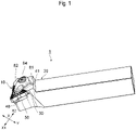
- FIG. 1 is a diagram depicting an example of a cutting tool 1 according to the present embodiment.
- the cutting tool 1 is a cutting edge replaceable type tool for machining.
- the cutting tool 1 includes a cutting insert 10 and a tool main unit (holding tool) 20 to which the cutting insert 10 is fixed.
- the tool main unit 20 is configured to selectively hold a plurality of types of cutting inserts 10 having three corner portions.
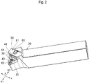
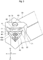
- the tool main unit 20 is formed in an approximately prism shape, and has a fixing portion 30 of the cutting insert 10. As illustrated in FIG. 2 and FIG. 3 , the fixing portion 30 includes a bottom face 40 which contacts with the bottom face of the cutting insert 10, and a side wall face 41 which contacts with the side face of the cutting insert 10.
- the bottom face 40 is formed using a top face of a shim 50 of the tool main unit 20, for example.
- the bottom face 40 may be formed using the tool main unit 20 itself instead of the shim 50.
- the bottom face 40 has an approximately equilateral triangular shape.
- the bottom face 40 is formed such that one of the apexes of the triangle faces the front end side of the tool main unit 20 (in the front end direction X1 in FIG. 2 and FIG. 3 ).
- a protruded portion 60 which protrudes upward and extends in the front end direction X1, is formed on the front end side of the bottom face 40.
- the bottom face 40 has a first bottom face 40a on the front end side, and a second bottom face 40b on the rear end side.
- the first bottom face 40a and the second bottom face 40b are generally both flat, and the first bottom face 40a is lower than the second bottom face 40b, therefore a step is formed between the first bottom face 40a and the second bottom face 40b.
- the protruded portion 60 is formed on the first bottom face 40a.
- a flat surface 61 on the rear portion of the bottom face 40 (area between the bottom face 40 and the side wall face 41), and this flat surface 61 is lower than the second bottom face 40b.
- the term “up” here refers to the upward direction when the tool main unit 20 is set as illustrated in FIG. 2 and FIG. 3 .
- the side wall face 41 is vertically formed at the edge of the bottom face 40 on the rear end side (rear end direction X2 in FIG. 2 and FIG. 3 ).
- the side wall face 41 is an approximately rectangular shape which extends in the left/right direction Y (direction perpendicular to the front/back direction X in FIG. 2 and FIG. 3 ).
- the side wall face 41 has a center wall face 70 in the center in the left/right direction Y and receding wall surfaces 71 that are connected to both ends of the center wall face 70, and recedes backward from the center wall face 70.
- the center wall face 70 is a rectangular flat surface.
- the center wall face 70 is slightly inclined (inclined forward) from the vertical plane of the bottom face 40, such that the upper side of the center wall face 70 locates forward in the front end direction X1, and the lower side thereof locates backward in the rear end direction X2 with respect to the vertical plane of the bottom face 40.
- the receded wall faces 71 are curved surfaces that gradually recede from the center wall face 70 in the left/right direction Y. Just like the center wall face 70, the receded wall faces 71 are slightly inclined (inclined forward) from the vertical plane of the bottom face 40, such that the upper side locates forward in the front end direction X1, and the lower side locates backward in the rear end direction X2 with respect to the vertical plane of the bottom face 40.
- the tool main unit 20 has a step 80 on the upper part of the side wall face 41, for example, and the step 80 is connected to a flat surface 81 located on the side in the rear end direction X2.
- a hole 83 to fix a clamp 82 (illustrated in FIG. 1 ), which holds the cutting insert 10 from above, is formed around the center of the flat surface 81.
- the clamp 82 is fixed to the flat surface 81 of the tool main unit 20 by a screw 84, and press-holds the end face of the cutting insert 10 and the inner face of the hole for fixing.
- the tool main unit 20 selectively holds a plurality of types of cutting inserts 10, including at least four types, which are: a negative type cutting insert of which angle of the corner portion exceeds 60°, a positive type cutting insert of which angle of the corner portion exceeds 60°, a negative type cutting insert of which angle of the corner portion is less than 60°, and a positive type cutting insert of which angle of the corner portion is less than 60°.
- FIG. 4 to FIG. 6 illustrate an example of a first cutting insert 90 which is a negative type cutting insert of which angle of the corner portion exceeds 60°.
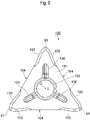
- FIG. 4 is a perspective view depicting an example of the first cutting insert 90
- FIG. 5 is a plan view of the first cutting insert 90 viewed from the first end face
- FIG. 6 is a side view of the first cutting insert 90.
- the first cutting insert 90 has an approximately flat triangular stereoscopic shape (approximately triangular prism shape), for example.
- Each of the three corner portions 91 of the first cutting insert 90 has an 80° point angle ⁇ 1 (indicated in FIG. 5 ).
- the first cutting insert 90 includes: a first end face 100 and a second end face which are approximately triangular-shaped and which face each other; three peripheral side faces 104 which connect the first end face 100 and the second end face 101, and which form crossing ridge lines 102 and 103 with the first end face 100 and with the second end face 101 respectively; and a fixing hole 105 which penetrates from the first end face 100 to the second end face 101.
- the crossing ridge lines 102 and 103 in the vicinity of each corner portion 91 constitute a cutting edge 120.
- the first end face 100 has the fixing hole 105 at the center thereof.
- the center O of the first end face 100 is located on the center axis C of the fixing hole 105.
- the first end face 100 includes three grooves 130, which is formed from the center O toward each apex (corner portion 91).
- the first end face 100 has a first chip breaker 131 and a second chip breaker 132 in the vicinity of a cutting edge 120 of each corner portion 91 respectively.
- the first chip breaker 131 is disposed in the vicinity of the apex of each corner portion 91 and includes one projection which projects upward, for example.
- the second chip breaker 132 includes a plurality of projections which project upward, for example, and is disposed along the crossing ridge line 102 extending from the vicinity of the apex of each corner portion 91 toward the apex of the next corner portion 91.
- the plurality of projections of the second chip breaker 132 are linearly disposed next to each other along the crossing ridge line 102.
- each peripheral side face 104 includes the corner face 140 which forms the corner portion 91, a center face 141 which is formed at the center between adjacent corner portions 91, and a connecting face 142 which is formed between the center face 141 and the corner face 140, and which connects the center face 141 and the corner face 140.
- the first cutting insert 90 which is a negative type, does not have a relief angle, and each peripheral side face 104 is a surface that is vertical to the first end face 100 and the second end face 101.
- an angle ⁇ 2 formed by the two center faces 141 on each side of the corner portion 91 is 60°.
- An angle ⁇ 4, formed by the two connecting faces 142 on each side of the corner portion 91 is 45°.
- a convex portion 150 which expands outward in the view from the first end face 100 (center axis C) side, is formed on the connecting portion between the connecting face 142 and the corner portion 91.
- This convex portion 150 becomes a contact portion that contacts with the side wall face 41 of the tool main unit 20.
- the crossing ridge lines 102 and 103 are inclined so as to be most distant from a virtual mid-plane P1 at the apex of the corner portion 91, and to be closest to the virtual mid-plane P1 at the center between the adjacent corner portions 91.
- the virtual mid-plane P1 is a virtual plane which is vertical to the center axis C, and which passes through the center between the first end face 100 and the second end face 101.
- the inclination angle ⁇ 5 of the crossing ridge line 102 or 103, with respect to the virtual mid-plane P1 is at least 1° and not more than 7°, for example.
- the crossing ridge lines 102 and 103 are linear in the side view in FIG. 6 , but may be curved.
- the inclination angle ⁇ 5 is an angle formed by: a line connecting a point of the crossing ridge line 102 or 103 that is most distant from the virtual mid-plane P1; and a point of the crossing ridge line 102 or 103 that is closest to the virtual mid-plane P1, and the virtual mid-plane P1.
- the fixing hole 105 penetrates at the center of the first cutting insert 90 in a direction from the first end face 100 to the second end face 101 (thickness direction).
- FIG. 7 to FIG. 10 illustrate an example of a positive type cutting insert 190 of which angle of the corner portion exceeds 60°.
- FIG. 7 is a perspective view depicting an example of the second cutting insert 190
- FIG. 8 is a plan view of the second cutting insert 190 viewed from the first end face 100
- FIG. 9 is a bottom view of the second cutting insert 190 viewed from the second end face 101.
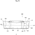
- FIG. 10 is a side view of the second cutting insert 190.
- the second cutting insert 190 which is a positive type, has a configuration that is different from the first cutting insert 90, which is a negative type.
- the second cutting insert 190 which is a positive type, has a relief angle, and the portions of each peripheral side face 104 except in the vicinity of the center face 141 (e.g. corner face 140 and connecting face 142) are surfaces inclined with respect to the vertical plane of the first end face 100.
- the first end face 100 includes the chip breakers 131 and 132, but does not include the grooves 130, for example.
- the second end face 101 has a different configuration from the first end face 100.
- the second end face 101 includes the grooves 130, but does not include the chip breakers 131 and 132, and has a flat bottom face except for the portions of the grooves 130.
- each peripheral side face 104 are inclined, having a 90° or less angle with respect to the first end face 100.
- an angle ⁇ 2 formed by the upper edges (enter crossing ridge lines) of the two center faces 141 on each side of the corner portion 91, is 60° in the view from the first end face 100 side in the center axis C direction.
- An angle ⁇ 3, formed by the upper edges (corner crossing ridge lines) of the two corner faces 140 on each side of the corner portion 91, is 80°.
- An angle ⁇ 4 formed by the upper edges (connecting crossing ridge lines) of the two connecting faces 142 on each side of the corner portion 91 is 45°.
- the inclination angle ⁇ 5 of the crossing ridge line 102 or 103, with respect to the virtual mid-plane P1 is at least 1° and not more than 22°, for example.
- a portion of the second cutting insert 190 has the same configuration as the first cutting insert 90, therefore this portion is denoted with the same reference sign as the first cutting insert 90, and description thereof is omitted.
- FIG. 11 to FIG. 13 illustrate a negative type cutting insert 290 of which angle of the corner portion is less than 60°.
- FIG. 11 is a perspective view depicting an example of the third cutting insert 290
- FIG. 12 is a plan view of the third cutting insert 290 viewed from the first end face 100
- FIG. 13 is a side view of the third cutting insert 290.
- the third cutting insert 290 has a different configuration as the first cutting insert 90, since the angle of the corner portion is less than 60°.
- each of the three corner portions 91 of the third cutting insert 290 has a 35° point angle ⁇ 1.
- an angle ⁇ 2 formed by the two center faces 141 on each side of the corner portion 91 is 60°.
- An angle ⁇ 3, formed by the two corner faces 140 on each side of the corner portion 91 is 35°.
- An angle ⁇ 4 formed by the two connecting faces 142 on each side of the corner portions 91 is 80°.
- a concave portion 300 which concaves inward, is formed in the plan view viewed from the first end face 100 side.
- the center face 141 becomes a contact portion that contacts with the side wall face 41 of the tool main unit 20.
- a portion of the third cutting insert 290, not mentioned here, has the same configuration as the first cutting insert 90, therefore this portion is denoted with the same reference sign as the first cutting insert 90, and description thereof is omitted.
- FIG. 14 to FIG. 17 illustrate a positive type fourth cutting insert 390 of which angle of the corner portion is less than 60°.
- FIG. 14 is a perspective view depicting an example of the fourth cutting insert 390
- FIG. 15 is a plan view of the fourth cutting insert 390 viewed from the first end face 100
- FIG. 16 is a bottom view of the fourth cutting insert 390 viewed from the second end face 101.
- FIG. 17 is a side view of the fourth cutting insert 390.
- the fourth cutting insert 390 which is a positive type, has a configuration that is different from the third cutting insert 290, which is a negative type.
- the fourth cutting insert 390 which is a positive type, has a relief angle, and the portions of each peripheral side face 104 except for the vicinity of the center face 141 (e.g. corner face 140 and the connecting face 142) are surfaces inclined with respect to the vertical plane of the first end face 100.
- the first end face 100 includes the chip breakers 131 and 132, but does not include the grooves 130, for example.
- the second end face 101 has a different configuration from the first end face 100.
- the second end face 101 includes the grooves 130, but does not include the chip breakers 131 and 132, and has a flat bottom face except for the portions of the grooves 130.
- each peripheral side face 104 are inclined, having a 90° or less angle with respect to the first end face 100.
- an angle ⁇ 2 formed by the upper edges (center crossing ridge lines) of the two center faces 141 on each side of the corner portion 91 is 60° in the view from the first end face 100 side in the center axis C direction.
- An angle ⁇ 3, formed by the upper edges (corner crossing ridge lines) of the two corner faces 140 on each side of the corner portion 91, is 35°.
- An angle ⁇ 4 formed by the upper edges (connecting crossing ridge lines) of the two connecting faces 142 on each side of the corner portion 91, is 80°.
- the upper edge of the center face 141 becomes a contact portion that contacts with the side wall face 41 of the tool main unit 20.
- a portion of the fourth cutting insert 390, not mentioned here, has the same configuration as the third cutting insert 290, therefore this portion is denoted with the same reference sign as the third cutting inserts 290, and description thereof is omitted.
- the above mentioned cutting tool 1 can selectively fix the cutting inserts 90, 190, 290 and 390, to the tool main unit 20.
- the first cutting insert 90 is placed in the fixing portion 30 of the tool main unit 20 in a state where one corner portion 91 is pointed toward the front end direction X1, the screw is inserted into the fixing hole 105, and the first cutting insert 90 is fixed to the fixing portion 30 by this screw. Further, the first cutting insert 90 is pressed from above by the clamp 82, as illustrated in FIG. 1 .
- the second end face 101 of the first cutting insert 90 contacts with the bottom face 40 of the fixing portion 30, and the groove 130 of second end face 101 engages with the protruded portion 60.
- One peripheral side face 104 of the first cutting insert 90 contacts with the tool main unit 20 at two locations of the receded wall faces 71 on both sides of the side wall face 41 of the fixing portion 30.
- the convex portion 150 (second portion), which is a connecting portion between the connecting face 142 on the peripheral side face 104 and the corner face 140, contacts with the receded wall faces 71 of the fixing portion 30.
- the convex portion 150 and each receded wall face 71 contact with each other at point F1.
- the second cutting insert 190 is placed in the fixing portion 30 of the tool main unit 20 in a state where one corner portion 91 is pointed toward the front end direction X1, and is fixed to the fixing portion 30 by the screw.
- the second cutting insert 190 is pressed from above by the clamp 82.
- the second end face 101 of the second cutting insert 190 contacts with the bottom face 40 of the fixing portion 30, and the groove 130 of the second end face 101 engages with the protruded portion 60.
- One peripheral side face 104 of the second cutting insert 190 contacts with the tool main unit 20 at one location of the center wall face 70 of the side wall face 41 of the fixing portion 30. For example, as illustrated in FIG.
- the center face 141 (first portion) of the peripheral side face 104 contacts with the center wall face 70 of the fixing portion 30.
- the upper parts of the center face 141 and the center wall face 70 contact with each other.
- the contact portion F2 between the center face 141 and the center wall face 70 is a line extending in the left/right direction Y.
- the third cutting insert 290 is placed in the fixing portion 30 of the tool main unit 20 in a state where one corner portion 91 is pointed toward the front end direction X1, and is fixed to the fixing portion 30 by the screw.
- the third cutting insert 290 is pressed from above by the clamp 82.
- the second end face 101 of the third cutting insert 290 contacts with the bottom face 40 of the fixing portion 30, and the groove 130 of the second end face 101 engages with the protruded portion 60.
- One peripheral side face 104 of the third cutting insert 290 contacts with the tool main unit 20 at one location of the center wall face 70 of the side wall face 41 of the fixing portion 30. For example, as illustrated in FIG.
- the center face 141 (first portion) of the peripheral side face 104 contacts with the center wall face 70 of the fixing portion 30. At this time, (only) the upper parts of the center face 141 and the center wall face 70 contact with each other. As illustrated in FIG. 23 , the contact portion F2 between the center face 141 and the center wall face 70 is a line extending in the left/right direction Y.
- the fourth cutting insert 390 is placed in the fixing portion 30 of the tool main unit 20 in a state where one corner portion 91 is pointed toward the front end direction X1, and is fixed to the fixing portion 30 by the screw.
- the fourth cutting insert 390 is pressed from above by the clamp 82.
- the second end face 101 of the fourth cutting insert 390 contacts with the bottom face 40 of the fixing portion 30, and the groove 130 of the second end face 101 engages with the protruded portion 60.
- One peripheral side face 104 of the fourth cutting insert 390 contacts with the tool main unit 20 at one location of the center wall face 70 of the side wall face 41 of the fixing portion 30. For example, as illustrated in FIG.
- the center face 141 (first portion) of the peripheral side face 104 contacts with the center wall face 70 of the fixing portion 30.
- the upper parts of the center face 141 and the center wall face 70 contact with each other.
- the contact portion F2 between the center face 141 and the center wall face 70 is a line extending in the left/right direction Y.
- the tool main unit 20 has a fixing portion 30 that can selectively fix a plurality of types of cutting inserts 10, including the negative type cutting insert 90 of which angle of the corner portion exceeds 60°, the positive type cutting insert 190 of which angle of the corner portion exceeds 60°, the negative type cutting insert 290 of which angle of the corner portion is less than 60°, and the positive type cutting insert 390 of which angle of the corner portion is less than 60°, and a portion of the side wall face 41 of the fixing portion 30, that contacts with the cutting insert 10, is different depending on the type of the cutting insert 10.
- the four types of cutting inserts 10 can be firmly held by one tool main unit 20.
- one tool main unit 20 can be used for a plurality of types of cutting inserts, even if a number of tool main units 20 that can be installed in a tool rest (e.g. turret) of a machine tool is limited, which is a major advantage of processing a variety of processing shapes for work materials, an ensuring operation efficiency.
- a tool rest e.g. turret
- the side wall face 41 of the fixing portion 30 has the center wall face 70 at the center, and the receded wall faces 71, which are connected to both ends of the center wall face 70, and are receded from the center wall face 70 in the rear end direction X2, and has the portions that contact with the cutting insert 10 in the center wall face 70 and the receded wall faces 71. Thereby the portion where the cutting insert 10 and the side wall face 41 contact can be selected appropriately depending on the type of the cutting insert 10.
- the side wall face 41 of the fixing portion 30 has portions that contact with the cutting insert 10 in the upper part of the center wall face 70 and the upper parts of the receded wall faces 71. Thereby the holding force of the tool main unit 20 on the cutting insert 10 can be increased.
- Three types of cutting inserts which are the positive type cutting insert 190 of which angle of the corner portion exceeds 60°, the negative type cutting insert 290 of which angle of the corner portion is less than 60°, and the positive type cutting insert 390 of which angle of the corner portion is less than 60°, contact the common first portion (center face 141) of the side wall face 41 of the fixing portion 30, and the negative type cutting insert 90, of which angle of the corner portion exceeds 60°, contacts a second portion (connecting face 142 and corner face 140), which is different from the common first portion contacted by the three types of cutting inserts 190, 290 and 390, of the side wall face 41 of the fixing portion 30.
- the tool main unit 20 can appropriately hold the cutting insert at portions where the holding force increases in accordance with the shape of the outer shell of the cutting insert 10.
- the second portion of the side wall face 41 of the fixing portion 30 is located at the outer side of the center of the side wall face 41 more distant from the first portion. Thereby the holding force of the tool main unit 20 in the rotating direction of the cutting insert 90 can be improved.
- the configuration of the cutting insert 10 (90, 190, 290, 390) is not limited to those described in the embodiments.
- the angle ⁇ 1 of the corner portion of the cutting insert 90 or 190 is not limited to 80°
- the angle ⁇ 1 of the corner portion of the cutting insert 290 or 390 is not limited to 35°.
- the negative type cutting insert may be a cutting insert that has no flank in the vicinity of the first end face 100 of the peripheral side face 104, but has a flank in the vicinity of the second end face 101.
- the tool main unit 20 may be able to hold not only the above mentioned cutting inserts 90, 190, 290 and 390, but also a cutting insert 10 having a different configuration (type).
- the present invention is useful to provide a cutting tool that can firmly hold the four types of cutting inserts by one tool main unit.
Landscapes
- Engineering & Computer Science (AREA)
- Mechanical Engineering (AREA)
- Physics & Mathematics (AREA)
- Geometry (AREA)
- Milling Processes (AREA)
- Cutting Tools, Boring Holders, And Turrets (AREA)
Abstract
Cutting tool 1 that can firmly hold four types of cutting inserts by one tool main unit 20. A cutting insert 10 of the cutting tool has an approximately triangular stereoscopic shape including three corner portions. The tool main unit has a fixing portion 30 that can selectively fix a plurality of types of cutting inserts, including: a negative type cutting insert whose angle of the corner portion exceeds 60°, a positive type cutting insert whose angle of the corner portion exceeds 60°; a negative type cutting insert whose angle of the corner portion is less than 60°; and a positive type cutting insert whose angle of the corner portion is less than 60°. The fixing portion has a bottom face 40 that contacts a bottom face of the cutting insert, and a side wall face 41 that contacts a side face of the cutting insert. A portion of the side wall face of the fixing portion which contacts the cutting insert differs depending on the type of the cutting insert.
Description
- The present invention relates to a cutting tool, a cutting insert and a holding tool.
- A cutting tool for machining normally includes a cutting insert and a tool main unit (holding tool) that holds the cutting insert. Some cutting inserts have an approximately triangular stereoscopic shape (approximately triangular prism shape) having three corner portions, and this type of cutting insert includes, for example, a type of which angle of the corner portion exceeds 60°, a type of which angle of corner portion does not exceed 60°, a negative type (not including a relief angle), a positive type (including a relief angle), and the like. These cutting inserts are fixed to a tool main unit and are used for machining (see Patent Publication
JP-A-2019-34358 Japanese Translation of PCT Application No. 2018-529535 - In the case of the above mentioned plurality of types of cutting inserts having an approximately triangular prism shape, the shapes of the outer shells are different from each other and have to be firmly fixed, hence these cutting inserts are fixed to dedicated tool main units respectively. Therefore when the cutting insert is replaced with a different type of cutting insert, the tool main unit is also replaced, which drops operation efficiency. Further, cost also increases since a different tool main unit has to be provided for each type of cutting insert. Furthermore, in a case where various different shapes of work materials that change daily are processed using the cutting inserts, a number of holding tools that can be provided is limited due to the constraints of the tool rest (e.g. turret) of a machine tool, and it is preferable that various types of cutting inserts, such as four types of cutting inserts, which are negative and positive type cutting inserts of which angle of the corner portion exceeds 60°, e.g. 80°, and negative and positive type cutting inserts of which angle of the corner portion is less than 60°, e.g. 35°, can be used with one holding tool.
- With the foregoing in view, it is an object of the present invention to provide a cutting tool, a cutting insert and a holding tool that can firmly hold a plurality of cutting inserts, including the above mentioned four types of cutting inserts, by one tool main unit.
- A cutting tool according to an aspect of the present invention is a cutting tool including a cutting insert and a tool main unit. The cutting insert has an approximately triangular stereoscopic shape including three corner portions. The tool main unit has a fixing portion that can selectively fix a plurality of types of cutting inserts, including a negative type cutting insert of which angle of the corner portion exceeds 60°, a positive type cutting insert of which angle of the corner portion exceeds 60°, a negative type cutting insert of which angle of the corner portion is less than 60°, and a positive type cutting insert of which angle of the corner portion is less than 60°. The fixing portion has a bottom face that contacts with a bottom face of the cutting insert, and a side wall face that contacts with a side face of the cutting insert, and a portion, which contacts with the cutting insert, of the side wall face of the fixing portion differs depending on the type of the cutting insert.
- According to this aspect, the four types of cutting inserts can be firmly held by one tool main unit.
- In the above aspect, the side wall face of the fixing portion may have, at a center, a center wall face, and receded wall faces which are connected to both ends of the center wall face and are receded further backward of the tool main unit than the center wall face, and have portions that contact with the cutting insert in the center wall face and the receded wall faces.
- In the above aspect, the side wall face of the fixing portion may have portions that contact with the cutting insert in an upper part of the center wall face and upper parts of the receded wall faces.
- In the above aspect, the cutting inserts may have three peripheral side faces each of which is located between adjacent corner portions, each of the peripheral side faces of the cutting insert may include: a corner face that constitutes a corner portion; a center face that is formed at a center between two adjacent corner portions; and a connecting face that is disposed between the center face and the corner face and connects the center face and the corner face. Either a first portion of the center face of the cutting insert or a second portion, constituted of the connecting face and the corner face, may contact with the side wall face of the fixing portion.
- In the above aspect, three types of cutting inserts, which are a positive type cutting insert of which angle of the corner portion exceeds 60°, a negative type cutting insert of which angle of the corner portion is less than 60°, and a positive type cutting insert of which angle of the corner portion is less than 60°, may contact a common first portion of the side wall face of the fixing portion, and a negative type cutting insert of which angle of the corner portion exceeds 60°, may contact a second portion, which is different from the common first portion contacted by the three types of cutting inserts, of the side wall face of the fixing portion.
- In the above aspect, the second portion of the side wall face of the fixing portion may be located further outward of the center of the side wall face than the first portion.
- A cutting insert according to another aspect of the present invention is a cutting insert having an approximately triangular stereoscopic shape including three corner portions of which angles exceed 60° or less than 60°, and having three peripheral side faces each of which is located between adjacent corner portions. Each of the peripheral side faces include: a corner face that constitutes a corner portion; a center face that is formed at a center between adjacent corner portions; and a connecting face that is disposed between the center face and the corner face and connects the center face and the corner face. A contact portion that contacts with a tool main unit, when the cutting insert is fixed to the tool main unit of the cutting tool, is formed either in a first portion of the center face or a second portion constituted of the connecting face and the corner face.
- In the above aspect, the cutting insert may be a positive type cutting insert of which angle of the corner portion exceeds 60°, a negative type cutting insert of which angle of the corner portion is less than 60°, or a positive type cutting insert of which angle of the corner portion is less than 60°, and a contact portion, which contacts with the tool main unit when the cutting insert is fixed to the tool main unit of the cutting tool, may be formed in the first portion of the center face.
- In the above aspect, the cutting insert may be a negative type cutting insert of which angle of the corner portion exceeds 60°, and a contact portion, which contacts with the tool main unit when the cutting insert is fixed to the tool main unit of the cutting tool, may be formed in a second portion constituted of the connecting face and the corner face.
- A holding tool according to another aspect of the present invention is a holding tool holding a cutting insert that has an approximately triangular stereoscopic shape including three corner portions, the holding tool including: a fixing portion that can selectively fix a plurality of types of cutting inserts including a negative type cutting insert of which angle of the corner portion exceeds 60°, a positive type cutting insert of which angle of the corner portion exceeds 60°, a negative type cutting insert of which angle of the corner portion is less than 60°, and a positive type cutting insert of which angle of the corner portion is less than 60°. The fixing portion has a bottom face that contacts with a bottom face of the cutting insert, and a side wall face that contacts with a side face of the cutting insert, and a portion, which contacts with the cutting insert, of the side wall face of the fixing portion differs depending on the type of the cutting insert.
- In the above aspect, the side wall face of the fixing portion may have, at a center, a center wall face, and receded wall faces which are connected to both ends of the center wall face and are receded further backward of a tool main unit than the center wall face, and have portions that contact with the cutting insert in the center wall face and the receded wall faces.
- In the above aspect, the side wall face of the fixing portion may have portions that contact with the cutting insert in the upper parts of the center wall face and the upper part of the receded wall faces.
- In the above aspect, three types of cutting inserts, which are a positive type cutting insert of which angle of the corner portion exceeds 60°, a negative type cutting insert of which angle of the corner portion is less than 60°, and a positive type cutting insert of which angle of the corner portion is less than 60°, may contact a common first portion of the side wall face of the fixing portion, and a negative type cutting insert of which angle of corner portion exceeds 60°, may contact a second portion, which is different from the common first portion contacted by the three types of cutting inserts, of the side wall face of the fixing portion.
- In the above aspect, the second portion of the side wall face of the fixing portion may be located further outward of the center of the side wall face than the first portion.
-
-
FIG. 1 is a perspective view of a cutting tool; -
FIG. 2 is a perspective view of a tool main unit; -
FIG. 3 is a front view of a fixing portion of the tool main unit; -
FIG. 4 is a perspective view of a first cutting insert; -
FIG. 5 is a plan view of the first cutting insert; -
FIG. 6 is a side view of the first cutting insert; -
FIG. 7 is a perspective view of a second cutting insert; -
FIG. 8 is a plan view of the second cutting insert; -
FIG. 9 is a bottom view of the second cutting insert; -
FIG. 10 is a side view of the second cutting insert; -
FIG. 11 is a perspective view of a third cutting insert; -
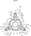
FIG. 12 is a plan view of the third cutting insert; -
FIG. 13 is a side view of the third cutting insert; -
FIG. 14 is a perspective view of a fourth cutting insert; -
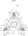
FIG. 15 is a plan view of the fourth cutting insert; -
FIG. 16 is a bottom view of the fourth cutting insert; -
FIG. 17 is a side view of the fourth cutting insert; -
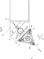
FIG. 18 is an enlarged plan view of the fixing portion of the tool main unit on which the first cutting insert is installed; -
FIG. 19 is a cross-sectional view at A-A inFIG. 18 ; -
FIG. 20 is a diagram depicting a contact portion between the cutting insert and the tool main unit; -
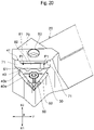
FIG. 21 is an enlarged plan view of the fixing portion of the tool main unit in which the second cutting insert is installed; -
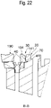
FIG. 22 is a cross-sectional view at B-B inFIG. 21 ; -
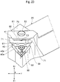
FIG. 23 is a diagram depicting a contact portion between the cutting insert and the tool main unit; -
FIG. 24 is an enlarged plan view of the fixing portion of the tool main unit in which the third cutting insert is installed; -
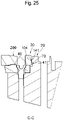
FIG. 25 is a cross-sectional view at C-C inFIG. 24 ; -
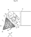
FIG. 26 is an enlarged plan view of the fixing portion of the tool main unit in which the fourth cutting insert is installed; and -
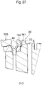
FIG. 27 is a cross-sectional view at D-D inFIG. 26 . - Preferred embodiments of the present invention will be described with reference to the drawings.
-
FIG. 1 is a diagram depicting an example of a cutting tool 1 according to the present embodiment. The cutting tool 1 is a cutting edge replaceable type tool for machining. The cutting tool 1 includes a cuttinginsert 10 and a tool main unit (holding tool) 20 to which the cuttinginsert 10 is fixed. - The tool
main unit 20 is configured to selectively hold a plurality of types of cutting inserts 10 having three corner portions. The toolmain unit 20 is formed in an approximately prism shape, and has a fixingportion 30 of the cuttinginsert 10. As illustrated inFIG. 2 andFIG. 3 , the fixingportion 30 includes abottom face 40 which contacts with the bottom face of the cuttinginsert 10, and a side wall face 41 which contacts with the side face of the cuttinginsert 10. - The
bottom face 40 is formed using a top face of ashim 50 of the toolmain unit 20, for example. However thebottom face 40 may be formed using the toolmain unit 20 itself instead of theshim 50. - The
bottom face 40 has an approximately equilateral triangular shape. Thebottom face 40 is formed such that one of the apexes of the triangle faces the front end side of the tool main unit 20 (in the front end direction X1 inFIG. 2 andFIG. 3 ). A protrudedportion 60, which protrudes upward and extends in the front end direction X1, is formed on the front end side of thebottom face 40. Thebottom face 40 has a firstbottom face 40a on the front end side, and a secondbottom face 40b on the rear end side. The firstbottom face 40a and the secondbottom face 40b are generally both flat, and the firstbottom face 40a is lower than the secondbottom face 40b, therefore a step is formed between the firstbottom face 40a and the secondbottom face 40b. The protrudedportion 60 is formed on the firstbottom face 40a. There is aflat surface 61 on the rear portion of the bottom face 40 (area between thebottom face 40 and the side wall face 41), and thisflat surface 61 is lower than the secondbottom face 40b. The term "up" here refers to the upward direction when the toolmain unit 20 is set as illustrated inFIG. 2 andFIG. 3 . - The
side wall face 41 is vertically formed at the edge of thebottom face 40 on the rear end side (rear end direction X2 inFIG. 2 andFIG. 3 ). Theside wall face 41 is an approximately rectangular shape which extends in the left/right direction Y (direction perpendicular to the front/back direction X inFIG. 2 andFIG. 3 ). Theside wall face 41 has a center wall face 70 in the center in the left/right direction Y and receding wall surfaces 71 that are connected to both ends of thecenter wall face 70, and recedes backward from thecenter wall face 70. - The
center wall face 70 is a rectangular flat surface. Thecenter wall face 70 is slightly inclined (inclined forward) from the vertical plane of thebottom face 40, such that the upper side of thecenter wall face 70 locates forward in the front end direction X1, and the lower side thereof locates backward in the rear end direction X2 with respect to the vertical plane of thebottom face 40. - The receded wall faces 71 are curved surfaces that gradually recede from the center wall face 70 in the left/right direction Y. Just like the
center wall face 70, the receded wall faces 71 are slightly inclined (inclined forward) from the vertical plane of thebottom face 40, such that the upper side locates forward in the front end direction X1, and the lower side locates backward in the rear end direction X2 with respect to the vertical plane of thebottom face 40. - The tool
main unit 20 has astep 80 on the upper part of theside wall face 41, for example, and thestep 80 is connected to aflat surface 81 located on the side in the rear end direction X2. Ahole 83 to fix a clamp 82 (illustrated inFIG. 1 ), which holds the cuttinginsert 10 from above, is formed around the center of theflat surface 81. As illustrated inFIG. 1 , theclamp 82 is fixed to theflat surface 81 of the toolmain unit 20 by ascrew 84, and press-holds the end face of the cuttinginsert 10 and the inner face of the hole for fixing. - The tool
main unit 20 selectively holds a plurality of types of cutting inserts 10, including at least four types, which are: a negative type cutting insert of which angle of the corner portion exceeds 60°, a positive type cutting insert of which angle of the corner portion exceeds 60°, a negative type cutting insert of which angle of the corner portion is less than 60°, and a positive type cutting insert of which angle of the corner portion is less than 60°. -
FIG. 4 to FIG. 6 illustrate an example of afirst cutting insert 90 which is a negative type cutting insert of which angle of the corner portion exceeds 60°.FIG. 4 is a perspective view depicting an example of thefirst cutting insert 90,FIG. 5 is a plan view of thefirst cutting insert 90 viewed from the first end face, andFIG. 6 is a side view of thefirst cutting insert 90. - As illustrated in
FIG. 4 , thefirst cutting insert 90 has an approximately flat triangular stereoscopic shape (approximately triangular prism shape), for example. Each of the threecorner portions 91 of thefirst cutting insert 90 has an 80° point angle α1 (indicated inFIG. 5 ). - As illustrated in
FIG. 4 to FIG. 6 , thefirst cutting insert 90 includes: afirst end face 100 and a second end face which are approximately triangular-shaped and which face each other; three peripheral side faces 104 which connect thefirst end face 100 and thesecond end face 101, and which form crossingridge lines first end face 100 and with thesecond end face 101 respectively; and a fixinghole 105 which penetrates from thefirst end face 100 to thesecond end face 101. Thecrossing ridge lines corner portion 91 constitute acutting edge 120. - As illustrated in
FIG. 4 andFIG. 5 , thefirst end face 100 has the fixinghole 105 at the center thereof. The center O of thefirst end face 100 is located on the center axis C of the fixinghole 105. Thefirst end face 100 includes threegrooves 130, which is formed from the center O toward each apex (corner portion 91). Thefirst end face 100 has afirst chip breaker 131 and asecond chip breaker 132 in the vicinity of acutting edge 120 of eachcorner portion 91 respectively. Thefirst chip breaker 131 is disposed in the vicinity of the apex of eachcorner portion 91 and includes one projection which projects upward, for example. Thesecond chip breaker 132 includes a plurality of projections which project upward, for example, and is disposed along thecrossing ridge line 102 extending from the vicinity of the apex of eachcorner portion 91 toward the apex of thenext corner portion 91. The plurality of projections of thesecond chip breaker 132 are linearly disposed next to each other along thecrossing ridge line 102. By thissecond chip breaker 132, the chip discharge performance can be improved in the back turning operation of the cuttinginsert 90. For example, thesecond end face 101 has the same configuration as thefirst end face 100. Thefirst cutting insert 90 can be used regardless whether thefirst end face 100 is the top face, or thesecond end face 101 is the top face. - As illustrated in
FIG. 4 andFIG. 6 , eachperipheral side face 104 includes thecorner face 140 which forms thecorner portion 91, acenter face 141 which is formed at the center betweenadjacent corner portions 91, and a connectingface 142 which is formed between thecenter face 141 and thecorner face 140, and which connects thecenter face 141 and thecorner face 140. Thefirst cutting insert 90, which is a negative type, does not have a relief angle, and eachperipheral side face 104 is a surface that is vertical to thefirst end face 100 and thesecond end face 101. - As illustrated in
FIG. 5 , in the plan view viewed from thefirst end face 100 side, an angle α2, formed by the two center faces 141 on each side of thecorner portion 91, is 60°. An angle α3, formed by the two corner faces 140 on each side of thecorner portion 91, is 80°. An angle α4, formed by the two connectingfaces 142 on each side of thecorner portion 91, is 45°. Thereby aconvex portion 150, which expands outward in the view from the first end face 100 (center axis C) side, is formed on the connecting portion between the connectingface 142 and thecorner portion 91. Thisconvex portion 150 becomes a contact portion that contacts with the side wall face 41 of the toolmain unit 20. - As illustrated in
FIG. 6 , thecrossing ridge lines corner portion 91, and to be closest to the virtual mid-plane P1 at the center between theadjacent corner portions 91. The virtual mid-plane P1 is a virtual plane which is vertical to the center axis C, and which passes through the center between thefirst end face 100 and thesecond end face 101. In the case of the negative type cutting insert of this example, it is preferable that the inclination angle α5 of thecrossing ridge line crossing ridge lines crossing ridge lines FIG. 6 , but may be curved. In this case, the inclination angle α5 is an angle formed by: a line connecting a point of thecrossing ridge line crossing ridge line - As illustrated in
FIG. 5 , the fixinghole 105 penetrates at the center of thefirst cutting insert 90 in a direction from thefirst end face 100 to the second end face 101 (thickness direction). -
FIG. 7 to FIG. 10 illustrate an example of a positivetype cutting insert 190 of which angle of the corner portion exceeds 60°.FIG. 7 is a perspective view depicting an example of thesecond cutting insert 190,FIG. 8 is a plan view of thesecond cutting insert 190 viewed from thefirst end face 100, andFIG. 9 is a bottom view of thesecond cutting insert 190 viewed from thesecond end face 101.FIG. 10 is a side view of thesecond cutting insert 190. - As illustrated in
FIG. 7 to FIG. 10 , thesecond cutting insert 190, which is a positive type, has a configuration that is different from thefirst cutting insert 90, which is a negative type. In other words, thesecond cutting insert 190, which is a positive type, has a relief angle, and the portions of eachperipheral side face 104 except in the vicinity of the center face 141 (e.g. corner face 140 and connecting face 142) are surfaces inclined with respect to the vertical plane of thefirst end face 100. - As illustrated in
FIG. 7 andFIG. 8 , thefirst end face 100 includes thechip breakers grooves 130, for example. As illustrated inFIG. 9 , thesecond end face 101 has a different configuration from thefirst end face 100. Thesecond end face 101 includes thegrooves 130, but does not include thechip breakers grooves 130. - As illustrated in
FIG. 10 , thecorner face 140 and the connectingface 142 of eachperipheral side face 104 are inclined, having a 90° or less angle with respect to thefirst end face 100. Then as illustrated inFIG. 8 , an angle α2, formed by the upper edges (enter crossing ridge lines) of the two center faces 141 on each side of thecorner portion 91, is 60° in the view from thefirst end face 100 side in the center axis C direction. An angle α3, formed by the upper edges (corner crossing ridge lines) of the two corner faces 140 on each side of thecorner portion 91, is 80°. An angle α4, formed by the upper edges (connecting crossing ridge lines) of the two connectingfaces 142 on each side of thecorner portion 91, is 45°. The vicinity of the upper edge of thecenter face 141 becomes a contact portion that contacts with the side wall face 41 of the toolmain unit 20. In the case of the positive type cutting insert of this example, it is preferable that the inclination angle α5 of thecrossing ridge line FIG. 10 ), is at least 1° and not more than 22°, for example. - A portion of the
second cutting insert 190, not mentioned here, has the same configuration as thefirst cutting insert 90, therefore this portion is denoted with the same reference sign as thefirst cutting insert 90, and description thereof is omitted. -
FIG. 11 to FIG. 13 illustrate a negativetype cutting insert 290 of which angle of the corner portion is less than 60°.FIG. 11 is a perspective view depicting an example of thethird cutting insert 290,FIG. 12 is a plan view of thethird cutting insert 290 viewed from thefirst end face 100, andFIG. 13 is a side view of thethird cutting insert 290. - As illustrated in
FIG. 11 to FIG. 13 , thethird cutting insert 290 has a different configuration as thefirst cutting insert 90, since the angle of the corner portion is less than 60°. In other words, as illustrated inFIG. 12 , each of the threecorner portions 91 of thethird cutting insert 290 has a 35° point angle α1. In a view viewed from thefirst end face 100 side in the center axis C direction, an angle α2, formed by the two center faces 141 on each side of thecorner portion 91, is 60°. An angle α3, formed by the two corner faces 140 on each side of thecorner portion 91, is 35°. An angle α4, formed by the two connectingfaces 142 on each side of thecorner portions 91, is 80°. Thereby, on the connecting portion between the connectingface 142 and thecorner face 140, aconcave portion 300, which concaves inward, is formed in the plan view viewed from thefirst end face 100 side. Here, thecenter face 141 becomes a contact portion that contacts with the side wall face 41 of the toolmain unit 20. A portion of thethird cutting insert 290, not mentioned here, has the same configuration as thefirst cutting insert 90, therefore this portion is denoted with the same reference sign as thefirst cutting insert 90, and description thereof is omitted. -
FIG. 14 to FIG. 17 illustrate a positive typefourth cutting insert 390 of which angle of the corner portion is less than 60°.FIG. 14 is a perspective view depicting an example of thefourth cutting insert 390,FIG. 15 is a plan view of thefourth cutting insert 390 viewed from thefirst end face 100, andFIG. 16 is a bottom view of thefourth cutting insert 390 viewed from thesecond end face 101.FIG. 17 is a side view of thefourth cutting insert 390. - As illustrated in
FIG. 14 to FIG. 17 , thefourth cutting insert 390, which is a positive type, has a configuration that is different from thethird cutting insert 290, which is a negative type. In other words, thefourth cutting insert 390, which is a positive type, has a relief angle, and the portions of eachperipheral side face 104 except for the vicinity of the center face 141 (e.g. corner face 140 and the connecting face 142) are surfaces inclined with respect to the vertical plane of thefirst end face 100. - As illustrated in
FIG. 14 andFIG. 15 , thefirst end face 100 includes thechip breakers grooves 130, for example. As illustrated inFIG. 16 , thesecond end face 101 has a different configuration from thefirst end face 100. Thesecond end face 101 includes thegrooves 130, but does not include thechip breakers grooves 130. - As illustrated in
FIG. 17 , thecorner face 140 and the connectingface 142 of eachperipheral side face 104 are inclined, having a 90° or less angle with respect to thefirst end face 100. Then as illustrated inFIG. 15 , an angle α2, formed by the upper edges (center crossing ridge lines) of the two center faces 141 on each side of thecorner portion 91, is 60° in the view from thefirst end face 100 side in the center axis C direction. An angle α3, formed by the upper edges (corner crossing ridge lines) of the two corner faces 140 on each side of thecorner portion 91, is 35°. An angle α4, formed by the upper edges (connecting crossing ridge lines) of the two connectingfaces 142 on each side of thecorner portion 91, is 80°. The upper edge of thecenter face 141 becomes a contact portion that contacts with the side wall face 41 of the toolmain unit 20. A portion of thefourth cutting insert 390, not mentioned here, has the same configuration as thethird cutting insert 290, therefore this portion is denoted with the same reference sign as the third cutting inserts 290, and description thereof is omitted. - The above mentioned cutting tool 1 can selectively fix the cutting inserts 90, 190, 290 and 390, to the tool
main unit 20. - As illustrated in
FIG. 18 , thefirst cutting insert 90 is placed in the fixingportion 30 of the toolmain unit 20 in a state where onecorner portion 91 is pointed toward the front end direction X1, the screw is inserted into the fixinghole 105, and thefirst cutting insert 90 is fixed to the fixingportion 30 by this screw. Further, thefirst cutting insert 90 is pressed from above by theclamp 82, as illustrated inFIG. 1 . Thesecond end face 101 of thefirst cutting insert 90 contacts with thebottom face 40 of the fixingportion 30, and thegroove 130 ofsecond end face 101 engages with the protrudedportion 60. Oneperipheral side face 104 of thefirst cutting insert 90 contacts with the toolmain unit 20 at two locations of the receded wall faces 71 on both sides of the side wall face 41 of the fixingportion 30. For example, as illustrated inFIG. 19 , the convex portion 150 (second portion), which is a connecting portion between the connectingface 142 on theperipheral side face 104 and thecorner face 140, contacts with the receded wall faces 71 of the fixingportion 30. At this time, (only) the upper parts of theconvex portion 150 and the receded wall faces 71 contact with each other. As illustrated inFIG. 20 , theconvex portion 150 and each recededwall face 71 contact with each other at point F1. - As illustrated in
FIG. 21 , thesecond cutting insert 190 is placed in the fixingportion 30 of the toolmain unit 20 in a state where onecorner portion 91 is pointed toward the front end direction X1, and is fixed to the fixingportion 30 by the screw. Thesecond cutting insert 190 is pressed from above by theclamp 82. Thesecond end face 101 of thesecond cutting insert 190 contacts with thebottom face 40 of the fixingportion 30, and thegroove 130 of thesecond end face 101 engages with the protrudedportion 60. Oneperipheral side face 104 of thesecond cutting insert 190 contacts with the toolmain unit 20 at one location of the center wall face 70 of the side wall face 41 of the fixingportion 30. For example, as illustrated inFIG. 22 , the center face 141 (first portion) of the peripheral side face 104 contacts with the center wall face 70 of the fixingportion 30. At this time, (only) the upper parts of thecenter face 141 and the center wall face 70 contact with each other. As illustrated inFIG. 23 , the contact portion F2 between thecenter face 141 and thecenter wall face 70 is a line extending in the left/right direction Y. - As illustrated in
FIG. 24 , thethird cutting insert 290 is placed in the fixingportion 30 of the toolmain unit 20 in a state where onecorner portion 91 is pointed toward the front end direction X1, and is fixed to the fixingportion 30 by the screw. Thethird cutting insert 290 is pressed from above by theclamp 82. Thesecond end face 101 of thethird cutting insert 290 contacts with thebottom face 40 of the fixingportion 30, and thegroove 130 of thesecond end face 101 engages with the protrudedportion 60. Oneperipheral side face 104 of thethird cutting insert 290 contacts with the toolmain unit 20 at one location of the center wall face 70 of the side wall face 41 of the fixingportion 30. For example, as illustrated inFIG. 25 , the center face 141 (first portion) of the peripheral side face 104 contacts with the center wall face 70 of the fixingportion 30. At this time, (only) the upper parts of thecenter face 141 and the center wall face 70 contact with each other. As illustrated inFIG. 23 , the contact portion F2 between thecenter face 141 and thecenter wall face 70 is a line extending in the left/right direction Y. - As illustrated in
FIG. 26 , thefourth cutting insert 390 is placed in the fixingportion 30 of the toolmain unit 20 in a state where onecorner portion 91 is pointed toward the front end direction X1, and is fixed to the fixingportion 30 by the screw. Thefourth cutting insert 390 is pressed from above by theclamp 82. Thesecond end face 101 of thefourth cutting insert 390 contacts with thebottom face 40 of the fixingportion 30, and thegroove 130 of thesecond end face 101 engages with the protrudedportion 60. Oneperipheral side face 104 of thefourth cutting insert 390 contacts with the toolmain unit 20 at one location of the center wall face 70 of the side wall face 41 of the fixingportion 30. For example, as illustrated inFIG. 27 , the center face 141 (first portion) of the peripheral side face 104 contacts with the center wall face 70 of the fixingportion 30. At this time, (only) the upper parts of thecenter face 141 and the center wall face 70 contact with each other. As illustrated inFIG. 23 , the contact portion F2 between thecenter face 141 and thecenter wall face 70 is a line extending in the left/right direction Y. - According to this embodiment, the tool
main unit 20 has a fixingportion 30 that can selectively fix a plurality of types of cutting inserts 10, including the negativetype cutting insert 90 of which angle of the corner portion exceeds 60°, the positivetype cutting insert 190 of which angle of the corner portion exceeds 60°, the negativetype cutting insert 290 of which angle of the corner portion is less than 60°, and the positivetype cutting insert 390 of which angle of the corner portion is less than 60°, and a portion of the side wall face 41 of the fixingportion 30, that contacts with the cuttinginsert 10, is different depending on the type of the cuttinginsert 10. Thereby the four types of cutting inserts 10 can be firmly held by one toolmain unit 20. As a result, even when the type of the cuttinginsert 10 is changed, the same toolmain unit 20 can be used, and there is no need to replace the toolmain unit 20, hence operation efficiency can be improved. Further, there is no need to provide a different toolmain unit 20 depending on the type of the cutting insert, and cost can be reduced. Furthermore, one toolmain unit 20 can be used for a plurality of types of cutting inserts, even if a number of toolmain units 20 that can be installed in a tool rest (e.g. turret) of a machine tool is limited, which is a major advantage of processing a variety of processing shapes for work materials, an ensuring operation efficiency. - The side wall face 41 of the fixing
portion 30 has the center wall face 70 at the center, and the receded wall faces 71, which are connected to both ends of thecenter wall face 70, and are receded from the center wall face 70 in the rear end direction X2, and has the portions that contact with the cuttinginsert 10 in thecenter wall face 70 and the receded wall faces 71. Thereby the portion where the cuttinginsert 10 and the side wall face 41 contact can be selected appropriately depending on the type of the cuttinginsert 10. - The side wall face 41 of the fixing
portion 30 has portions that contact with the cuttinginsert 10 in the upper part of thecenter wall face 70 and the upper parts of the receded wall faces 71. Thereby the holding force of the toolmain unit 20 on the cuttinginsert 10 can be increased. - Either the first portion of the
center face 141 of the cuttinginsert 10, or the second portion constituted of the connectingface 142 and thecorner face 140, contact with the side wall face 41 of the fixingportion 30, hence the portion where the cuttinginsert 10 and the side wall face 41 contact can be selected appropriately depending on the type of the cuttinginsert 10. - Three types of cutting inserts, which are the positive
type cutting insert 190 of which angle of the corner portion exceeds 60°, the negativetype cutting insert 290 of which angle of the corner portion is less than 60°, and the positivetype cutting insert 390 of which angle of the corner portion is less than 60°, contact the common first portion (center face 141) of the side wall face 41 of the fixingportion 30, and the negativetype cutting insert 90, of which angle of the corner portion exceeds 60°, contacts a second portion (connectingface 142 and corner face 140), which is different from the common first portion contacted by the three types of cuttinginserts portion 30. Thereby the toolmain unit 20 can appropriately hold the cutting insert at portions where the holding force increases in accordance with the shape of the outer shell of the cuttinginsert 10. - The second portion of the side wall face 41 of the fixing
portion 30 is located at the outer side of the center of the side wall face 41 more distant from the first portion. Thereby the holding force of the toolmain unit 20 in the rotating direction of the cuttinginsert 90 can be improved. - Although embodiments of the present invention were described with reference to the accompanying drawings, the present invention is not limited to these examples. It is obvious that an expert skilled in the art can arrive at various changes and modifications within the scope of the spirit described in the Claims, and it should be understood that these changes and modifications are included in the technical scope of the present invention.
- For example, the configuration of the cutting insert 10 (90, 190, 290, 390) is not limited to those described in the embodiments. For example, the angle α1 of the corner portion of the cutting
insert insert first end face 100 of theperipheral side face 104, but has a flank in the vicinity of thesecond end face 101. The toolmain unit 20 may be able to hold not only the above mentioned cutting inserts 90, 190, 290 and 390, but also a cuttinginsert 10 having a different configuration (type). - The present invention is useful to provide a cutting tool that can firmly hold the four types of cutting inserts by one tool main unit.
Claims (14)
- A cutting tool comprising a cutting insert and a tool main unit, whereinthe cutting insert has an approximately triangular stereoscopic shape including three corner portions,the tool main unit has a fixing portion that can selectively fix a plurality of types of cutting inserts, including a negative type cutting insert of which angle of the corner portion exceeds 60°, a positive type cutting insert of which angle of the corner portion exceeds 60°, a negative type cutting insert of which angle of the corner portion is less than 60°, and a positive type cutting insert of which angle of the corner portion is less than 60°,the fixing portion has a bottom face that contacts with a bottom face of the cutting insert, and a side wall face that contacts with a side face of the cutting insert, anda portion, which contacts with the cutting insert, of the side wall face of the fixing portion differs depending on the type of the cutting insert.
- The cutting tool according to Claim 1, wherein
the side wall face of the fixing portion has, at a center, a center wall face, and receded wall faces which are connected to both ends of the center wall face and are receded further backward of the tool main unit than the center wall face, and has portions that contact with the cutting insert in the center wall face and the receded wall faces. - The cutting tool according to Claim 2, wherein
the side wall face of the fixing portion has portions that contact with the cutting insert in an upper part of the center wall face and upper parts of the receded wall faces. - The cutting tool according to one of Claims 1 to 3, whereinthe cutting insert has three peripheral side faces each of which is located between adjacent corner portions,each of the peripheral side faces of the cutting insert includes: a corner face that constitutes a corner portion; a center face that is formed at a center between two adjacent corner portions; and a connecting face that is disposed between the center face and the corner face and connects the center face and the corner face, andeither a first portion of the center face of the cutting insert or a second portion, constituted of the connecting face and the corner face, contacts with the side wall face of the fixing portion.
- The cutting tool according to any one of Claims 1 to 4, whereinthree types of cutting inserts, which are a positive type cutting insert of which angle of the corner portion exceeds 60°, a negative type cutting insert of which angle of the corner portion is less than 60°, and a positive type cutting insert of which angle of the corner portion is less than 60°, contact a common first portion of the side wall face of the fixing portion, anda negative type cutting insert, of which angle of the corner portion exceeds 60°, contacts a second portion, which is different from the common first portion contacted by the three types of cutting inserts, of the side wall face of the fixing portion.
- The cutting tool according to Claim 5, wherein
the second portion of the side wall face of the fixing portion is located further outward of the center of the side wall face than the first portion. - A cutting insert having an approximately triangular stereoscopic shape including three corner portions of which angles exceed 60° or less than 60°, and having three peripheral side faces each of which is located between adjacent corner portions, whereineach of the peripheral side faces include: a corner face that constitutes a corner portion; a center face that is formed at a center between adjacent corner portions; and a connecting face that is disposed between the center face and the corner face and connects the center face and the corner face, anda contact portion that contacts with a tool main unit, when the cutting insert is fixed to the tool main unit of the cutting tool, is formed either in a first portion of the center face or a second portion constituted of the connecting face and the corner face.
- The cutting insert according to Claim 7, whereinthe cutting insert is a positive type cutting insert of which angle of the corner portion exceeds 60°, a negative type cutting insert of which angle of the corner portion is less than 60°, or a positive type cutting insert of which angle of the corner portion is less than 60°, anda contact portion, which contacts with the tool main unit when the cutting insert is fixed to the tool main unit of the cutting tool, is formed in the first portion of the center face.
- The cutting insert according to Claim 7, whereinthe cutting insert is a negative type cutting insert of which angle of the corner portion exceeds 60°, anda contact portion, which contacts with the tool main unit when the cutting insert is fixed to the tool main unit of the cutting tool, is formed in the second portion constituted of the connecting face and the corner face.
- A holding tool holding a cutting insert that has an approximately triangular stereoscopic shape including three corner portions, the holding tool comprising:a fixing portion that can selectively fix a plurality of types of cutting inserts including a negative type cutting insert of which angle of the corner portion exceeds 60°, a positive type cutting insert of which angle of the corner portion exceeds 60°, a negative type cutting insert of which angle of the corner portion is less than 60°, and a positive type cutting insert of which angle of the corner portion is less than 60°, whereinthe fixing portion has a bottom face that contacts with a bottom face of the cutting insert, and a side wall face that contacts with a side face of the cutting insert, anda portion, which contacts with the cutting insert, of the side wall face of the fixing portion differs depending on the type of the cutting insert.
- The holding tool according to Claim 10, wherein
the side wall face of the fixing portion has, at a center, a center wall face, and receded wall faces which are connected to both ends of the center wall face and are receded further backward of a tool main unit than the center wall face, and has portions that contact with the cutting insert in the center wall face and the receded wall faces. - The holding tool according to Claim 11, wherein
the side wall face of the fixing portion has portions that contact with the cutting insert in the upper portion of the center wall face and the upper parts of the receded wall faces. - The holding tool according to any one of Claims 10 to 12, whereinthree types of cutting inserts, which are a positive type cutting insert of which angle of the corner part exceeds 60°, a negative type cutting insert of which angle of the corner portion is less than 60°, and a positive type cutting insert of which angle of the corner portion is less than 60°, contact a common first portion of the side wall face of the fixing portion, anda negative type cutting insert, of which angle of the corner portion exceeds 60°, contacts a second portion, which is different from the common first portion contacted by the three types of cutting inserts, of the side wall face of the fixing portion.
- The holding tool according to Claim 13, wherein
the second portion of the side wall face of the fixing portion is located further outward of the center of the side wall face than the first portion.
Applications Claiming Priority (1)
| Application Number | Priority Date | Filing Date | Title |
|---|---|---|---|
| JP2021024890A JP7299936B2 (en) | 2021-02-19 | 2021-02-19 | Cutting tools, cutting inserts and holding fixtures |
Publications (1)
| Publication Number | Publication Date |
|---|---|
| EP4046731A1 true EP4046731A1 (en) | 2022-08-24 |
Family
ID=78822315
Family Applications (1)
| Application Number | Title | Priority Date | Filing Date |
|---|---|---|---|
| EP21212779.9A Pending EP4046731A1 (en) | 2021-02-19 | 2021-12-07 | Cutting tool, cutting insert and holding tool |
Country Status (4)
| Country | Link |
|---|---|
| US (1) | US11786976B2 (en) |
| EP (1) | EP4046731A1 (en) |
| JP (1) | JP7299936B2 (en) |
| CN (1) | CN114951718B (en) |
Cited By (1)
| Publication number | Priority date | Publication date | Assignee | Title |
|---|---|---|---|---|
| EP4450196A1 (en) * | 2023-04-20 | 2024-10-23 | AB Sandvik Coromant | Turning tool kit and cutting insert therefor |
Families Citing this family (2)
| Publication number | Priority date | Publication date | Assignee | Title |
|---|---|---|---|---|
| JP7041408B1 (en) * | 2021-04-30 | 2022-03-24 | 株式会社タンガロイ | Cutting insert |
| US20250222525A1 (en) * | 2024-01-08 | 2025-07-10 | Iscar, Ltd. | Turning cutting insert with corner cutting portion having reduced nose angle and turning tool |
Citations (3)
| Publication number | Priority date | Publication date | Assignee | Title |
|---|---|---|---|---|
| EP1935538A1 (en) * | 2006-12-21 | 2008-06-25 | Sandvik Intellectual Property HB | A turning tool, as well as a basic body and a shim plate for such tools |
| WO2013109043A1 (en) * | 2012-01-17 | 2013-07-25 | Taegutec Ltd. | Cutting insert for turning and cutting tool assembly including the same |
| JP2019034358A (en) | 2017-08-10 | 2019-03-07 | 株式会社タンガロイ | Cutting insert and cutting tool |
Family Cites Families (23)
| Publication number | Priority date | Publication date | Assignee | Title |
|---|---|---|---|---|
| IL123685A (en) | 1998-03-16 | 2001-09-13 | Iscar Ltd | Modular cutting tool assembly |
| US6379087B1 (en) * | 2000-02-07 | 2002-04-30 | Kennametal Inc. | Cutting insert with split face clamping surfaces and toolholder therefor |
| US6527485B1 (en) * | 2000-11-22 | 2003-03-04 | Tooling Specialties, Inc. | Threading apparatus |
| US20030206777A1 (en) * | 2002-05-03 | 2003-11-06 | Gyllengahm Ulf Stefan | Metal cutting insert having straight cutting edge and curved abutment surface |
| JP4155838B2 (en) | 2003-02-14 | 2008-09-24 | 住友電工ハードメタル株式会社 | Replaceable blade tip and cutting tool using the same |
| US7001115B2 (en) * | 2003-07-21 | 2006-02-21 | Kennametal Inc. | Cutting insert and toolholder for holding the same |
| JP4797526B2 (en) | 2005-09-13 | 2011-10-19 | 株式会社タンガロイ | Throwaway tip |
| US7607868B2 (en) * | 2006-04-24 | 2009-10-27 | Valenite Llc | Side locking insert and material removal tool with same |
| BRPI0712550A2 (en) * | 2006-06-06 | 2012-10-16 | Mitsubishi Materials Corporation | cutting tool and cutting insert |
| DE102006028062B4 (en) * | 2006-06-12 | 2008-09-18 | Vargus Ltd. | Indexable insert |
| JP2009066746A (en) | 2006-11-22 | 2009-04-02 | Mitsubishi Materials Corp | Cutting insert |
| SE530701C2 (en) * | 2006-12-21 | 2008-08-19 | Sandvik Intellectual Property | Turning tools and lathe inserts where the engaging means of the insert are located in the triangle |
| KR100886455B1 (en) | 2006-12-27 | 2009-03-04 | 한국야금 주식회사 | Cutting insert for high-efficient cutting |
| WO2010150907A1 (en) * | 2009-06-26 | 2010-12-29 | 京セラ株式会社 | Cutting insert, cutting tool, and method for manufacturing cut product using same |
| US8807884B2 (en) * | 2009-12-18 | 2014-08-19 | Kennametal Inc. | Tool holder for multiple differently-shaped cutting inserts |
| JP5161324B2 (en) * | 2010-03-31 | 2013-03-13 | 日本特殊陶業株式会社 | Cutting tool for boring |
| DE102012000245A1 (en) * | 2011-01-14 | 2012-07-19 | Kennametal India Limited | A drill bit insert, a drilling tool, and a method of assembling it |
| JP5553128B2 (en) * | 2011-02-24 | 2014-07-16 | 株式会社タンガロイ | Cutting insert and cutting edge exchangeable end mill |
| EP2581157B1 (en) * | 2011-10-11 | 2020-04-01 | VARGUS Ltd. | Cutting tool for grooving and parting operations |
| EP2664399B1 (en) * | 2012-05-15 | 2017-01-04 | VARGUS Ltd. | Cutting tool |
| US20150063926A1 (en) * | 2013-08-30 | 2015-03-05 | Kennametal Inc. | Indexable cutting insert with coolant delivery |
| EP3153260B1 (en) | 2015-10-09 | 2018-05-23 | Sandvik Intellectual Property AB | Turning insert and method |
| US11813678B2 (en) * | 2017-11-02 | 2023-11-14 | Moldino Tool Engineering, Ltd. | Cutting insert and indexable cutting tool |
-
2021
- 2021-02-19 JP JP2021024890A patent/JP7299936B2/en active Active
- 2021-11-04 CN CN202111302784.XA patent/CN114951718B/en active Active
- 2021-11-09 US US17/454,150 patent/US11786976B2/en active Active
- 2021-12-07 EP EP21212779.9A patent/EP4046731A1/en active Pending
Patent Citations (3)
| Publication number | Priority date | Publication date | Assignee | Title |
|---|---|---|---|---|
| EP1935538A1 (en) * | 2006-12-21 | 2008-06-25 | Sandvik Intellectual Property HB | A turning tool, as well as a basic body and a shim plate for such tools |
| WO2013109043A1 (en) * | 2012-01-17 | 2013-07-25 | Taegutec Ltd. | Cutting insert for turning and cutting tool assembly including the same |
| JP2019034358A (en) | 2017-08-10 | 2019-03-07 | 株式会社タンガロイ | Cutting insert and cutting tool |
Cited By (2)
| Publication number | Priority date | Publication date | Assignee | Title |
|---|---|---|---|---|
| EP4450196A1 (en) * | 2023-04-20 | 2024-10-23 | AB Sandvik Coromant | Turning tool kit and cutting insert therefor |
| WO2024217726A1 (en) * | 2023-04-20 | 2024-10-24 | Ab Sandvik Coromant | Turning tool kit and cutting insert therefor |
Also Published As
| Publication number | Publication date |
|---|---|
| JP7299936B2 (en) | 2023-06-28 |
| CN114951718A (en) | 2022-08-30 |
| US11786976B2 (en) | 2023-10-17 |
| US20220266349A1 (en) | 2022-08-25 |
| CN114951718B (en) | 2024-02-02 |
| JP2022126990A (en) | 2022-08-31 |
Similar Documents
| Publication | Publication Date | Title |
|---|---|---|
| EP4046731A1 (en) | Cutting tool, cutting insert and holding tool | |
| RU2455128C2 (en) | Cutting plate | |
| RU2470744C2 (en) | Tangential cutting plate | |
| KR100887787B1 (en) | Cutting insert | |
| KR101130430B1 (en) | Double-sided cutting insert and milling cutter mounting the same | |
| US7001115B2 (en) | Cutting insert and toolholder for holding the same | |
| JP6048715B1 (en) | Cutting inserts, tool bodies and cutting tools | |
| CN102066029A (en) | Cutting insert, cutting tool, and cutting method using cutting insert and cutting tool | |
| KR20110094015A (en) | Double sided cutting inserts and cutting tools with them | |
| KR100937459B1 (en) | Tangential cutting insert | |
| US11717895B2 (en) | Cutting insert and cutting tool assembly including same | |
| US9227246B2 (en) | Cutting tool for grooving and parting operations | |
| CN104487194A (en) | Cutting insert and face milling cutter using same | |
| US11090740B2 (en) | Rotary cutting body having insert pocket with seat surface provided with a plurality of abutment elements and rotary cutting tool | |
| US11833593B2 (en) | Square-shaped insert for bar-peeling and insert-holder tool for same | |
| JPWO2015137508A1 (en) | Cutting inserts, tool bodies and cutting tools | |
| KR20130029199A (en) | Tangential cutting insert | |
| CN115213442A (en) | Cutting inserts and cutting tools | |
| CN103372661A (en) | Indexable cutting insert and a tool for chip removing machining, as well as a basic body for the tool | |
| CN110899804B (en) | Cutting insert and cutting tool | |
| CN118848041B (en) | Cutting inserts and cutting tools | |
| JPH0634893Y2 (en) | End mill | |
| RU2823270C1 (en) | Square insert for centerless turning of workpiece and tool-holder therefor | |
| JP2018149617A (en) | Blade edge replaceable cutting tool | |
| CN118234588A (en) | Cutting insert and cutting tool equipped with the same |
Legal Events
| Date | Code | Title | Description |
|---|---|---|---|
| PUAI | Public reference made under article 153(3) epc to a published international application that has entered the european phase |
Free format text: ORIGINAL CODE: 0009012 |
|
| STAA | Information on the status of an ep patent application or granted ep patent |
Free format text: STATUS: REQUEST FOR EXAMINATION WAS MADE |
|
| 17P | Request for examination filed |
Effective date: 20211226 |
|
| AK | Designated contracting states |
Kind code of ref document: A1 Designated state(s): AL AT BE BG CH CY CZ DE DK EE ES FI FR GB GR HR HU IE IS IT LI LT LU LV MC MK MT NL NO PL PT RO RS SE SI SK SM TR |
|
| STAA | Information on the status of an ep patent application or granted ep patent |
Free format text: STATUS: EXAMINATION IS IN PROGRESS |
|
| 17Q | First examination report despatched |
Effective date: 20241031 |