EP4046350B1 - Method for providing an emergency response service and emergency response service system - Google Patents
Method for providing an emergency response service and emergency response service system Download PDFInfo
- Publication number
- EP4046350B1 EP4046350B1 EP19789638.4A EP19789638A EP4046350B1 EP 4046350 B1 EP4046350 B1 EP 4046350B1 EP 19789638 A EP19789638 A EP 19789638A EP 4046350 B1 EP4046350 B1 EP 4046350B1
- Authority
- EP
- European Patent Office
- Prior art keywords
- emergency
- iot device
- iot
- pidf
- subscriber
- Prior art date
- Legal status (The legal status is an assumption and is not a legal conclusion. Google has not performed a legal analysis and makes no representation as to the accuracy of the status listed.)
- Active
Links
Images


Classifications
-
- H—ELECTRICITY
- H04—ELECTRIC COMMUNICATION TECHNIQUE
- H04L—TRANSMISSION OF DIGITAL INFORMATION, e.g. TELEGRAPHIC COMMUNICATION
- H04L65/00—Network arrangements, protocols or services for supporting real-time applications in data packet communication
- H04L65/10—Architectures or entities
- H04L65/102—Gateways
- H04L65/1023—Media gateways
- H04L65/103—Media gateways in the network
-
- H—ELECTRICITY
- H04—ELECTRIC COMMUNICATION TECHNIQUE
- H04L—TRANSMISSION OF DIGITAL INFORMATION, e.g. TELEGRAPHIC COMMUNICATION
- H04L65/00—Network arrangements, protocols or services for supporting real-time applications in data packet communication
- H04L65/10—Architectures or entities
- H04L65/1063—Application servers providing network services
-
- H—ELECTRICITY
- H04—ELECTRIC COMMUNICATION TECHNIQUE
- H04L—TRANSMISSION OF DIGITAL INFORMATION, e.g. TELEGRAPHIC COMMUNICATION
- H04L65/00—Network arrangements, protocols or services for supporting real-time applications in data packet communication
- H04L65/1066—Session management
- H04L65/1069—Session establishment or de-establishment
-
- H—ELECTRICITY
- H04—ELECTRIC COMMUNICATION TECHNIQUE
- H04L—TRANSMISSION OF DIGITAL INFORMATION, e.g. TELEGRAPHIC COMMUNICATION
- H04L65/00—Network arrangements, protocols or services for supporting real-time applications in data packet communication
- H04L65/1066—Session management
- H04L65/1101—Session protocols
- H04L65/1104—Session initiation protocol [SIP]
-
- H—ELECTRICITY
- H04—ELECTRIC COMMUNICATION TECHNIQUE
- H04L—TRANSMISSION OF DIGITAL INFORMATION, e.g. TELEGRAPHIC COMMUNICATION
- H04L67/00—Network arrangements or protocols for supporting network services or applications
- H04L67/01—Protocols
- H04L67/12—Protocols specially adapted for proprietary or special-purpose networking environments, e.g. medical networks, sensor networks, networks in vehicles or remote metering networks
-
- H—ELECTRICITY
- H04—ELECTRIC COMMUNICATION TECHNIQUE
- H04L—TRANSMISSION OF DIGITAL INFORMATION, e.g. TELEGRAPHIC COMMUNICATION
- H04L67/00—Network arrangements or protocols for supporting network services or applications
- H04L67/50—Network services
- H04L67/52—Network services specially adapted for the location of the user terminal
-
- H—ELECTRICITY
- H04—ELECTRIC COMMUNICATION TECHNIQUE
- H04L—TRANSMISSION OF DIGITAL INFORMATION, e.g. TELEGRAPHIC COMMUNICATION
- H04L67/00—Network arrangements or protocols for supporting network services or applications
- H04L67/50—Network services
- H04L67/54—Presence management, e.g. monitoring or registration for receipt of user log-on information, or the connection status of the users
-
- H—ELECTRICITY
- H04—ELECTRIC COMMUNICATION TECHNIQUE
- H04L—TRANSMISSION OF DIGITAL INFORMATION, e.g. TELEGRAPHIC COMMUNICATION
- H04L67/00—Network arrangements or protocols for supporting network services or applications
- H04L67/50—Network services
- H04L67/56—Provisioning of proxy services
- H04L67/562—Brokering proxy services
-
- G—PHYSICS
- G16—INFORMATION AND COMMUNICATION TECHNOLOGY [ICT] SPECIALLY ADAPTED FOR SPECIFIC APPLICATION FIELDS
- G16Y—INFORMATION AND COMMUNICATION TECHNOLOGY SPECIALLY ADAPTED FOR THE INTERNET OF THINGS [IoT]
- G16Y20/00—Information sensed or collected by the things
- G16Y20/10—Information sensed or collected by the things relating to the environment, e.g. temperature; relating to location
-
- H—ELECTRICITY
- H04—ELECTRIC COMMUNICATION TECHNIQUE
- H04M—TELEPHONIC COMMUNICATION
- H04M2242/00—Special services or facilities
- H04M2242/15—Information service where the information is dependent on the location of the subscriber
-
- H—ELECTRICITY
- H04—ELECTRIC COMMUNICATION TECHNIQUE
- H04M—TELEPHONIC COMMUNICATION
- H04M3/00—Automatic or semi-automatic exchanges
- H04M3/42—Systems providing special services or facilities to subscribers
- H04M3/50—Centralised arrangements for answering calls; Centralised arrangements for recording messages for absent or busy subscribers ; Centralised arrangements for recording messages
- H04M3/51—Centralised call answering arrangements requiring operator intervention, e.g. call or contact centers for telemarketing
- H04M3/5116—Centralised call answering arrangements requiring operator intervention, e.g. call or contact centers for telemarketing for emergency applications
Definitions
- the present invention relates to a method for providing an emergency response service and to an emergency response service system.
- NG911 Next Generation 911
- IP Internet Protocol
- VoIP Voice over Internet Protocol
- IoT Internet of Things
- the document WO 2014/018387 A2 relates to an i3 proxy module.
- An i3 proxy module is provided within a 911 service provider network (e.g., at the VoIP positioning center) to respond to a VoIP i2 SIP INVITE destined for a PSAP having i3 architecture.
- the i3 proxy module responds to the VoIP i2 SIP INVITE by generating a VoIP i3 SIP INVITE with PIDF-LO and routing the same to the i3 emergency services routing proxy (ESRP) within the i3 network.
- ESRP emergency services routing proxy
- an i3 SIP INVITE with PIDF-LO is sent from an i3 proxy module associated with an i2-based VoIP positioning center (VPC).
- legacy originating service provider (OSP) carrier networks are now enabled to route an emergency call to a PSAP having an i3 ESInet architecture.
- OSP legacy originating service provider
- the emergency response services also would need a dedicated system to handle such information.
- the present invention is based on the object to provide a method for providing an emergency response service and an emergency response service system according to which more precise emergency data may be provided in the event of an emergency.
- a method for providing an emergency response service based on the Internet Protocol, IP wherein an emergency call initiated by a subscriber due to an emergency situation is received by a SIP server together with location information, and wherein the SIP server associates the location information with the subscriber that initiated the emergency call, wherein the method comprises the steps of connecting at least one Internet of Things IoT device belonging to the subscriber to the SIP server; associating, in the SIP servers, the at least one IoT device to the location information; receiving at the SIP server, from the at least one IoT device, real time data associated with the emergency situation; and transmitting the real time data associated with the emergency situation to an emergency service routing proxy ESRP of an emergency IP network solution EsiNet.
- an IoT device as a camera located in the branch office at a location where a fire broke out, is able to provide additional information on the emergency situation, as how severe the fire is, and where it is located exactly.
- the handling of an emergency may be improved significantly.
- an innovative solution is provided so as to unify the information provided by the IoT devices in order to integrate both NG911 systems and security monitoring and measurement devices from a location served by the emergency services.
- the SIP server is a SIP Proxy, a SIP Session Border Controller, an IP PBX or any other SIP entity.
- the IoT devices are security monitoring and measurement devices located in or close to a branch office of the subscriber.
- the IoT devices are located somewhere else, i.e., not within the branch office itself.
- the method further comprises a step of associating the location information to the subscriber.
- the location information is associated to the subscriber by assigning it to a single Destination Number DN or a range of DNs, a single IP number of an IP subnet, or to a physical port.
- the method may further comprise a step of associating the subscriber and the at least one IoT device.
- the at least one IoT device is a sensor and/or a monitoring device.
- the method further includes a step of extending Presence Information Data Format PIDF for transporting data received from the at least one IoT device to the ESRP.
- the PIDF-LO is used for transporting the location information of the at least one IoT device to the ESRP.
- the method further includes a step of automatically generating an emergency call from an IoT device event.
- the PIDF may comprise a contact element, in particular, an URL of the contact address indicating how a person or entity of at least one IoT device can be reached.
- the PIDF may further comprise a timestamp element that designates the time at which the PIDF document was created.
- the PDIF document is an XML document.
- an emergency response service system comprising at least one branch office connected to a VoIP network by a SIP server, the branch office being served by an Emergency IP Network Solution EsiNet, wherein the system is adapted to carry out the method specified above.
- At least one IoT device is connected to the SIP server, the at least one IoT device being connected to an IoT management system or to an IoT gateway.
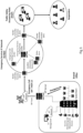
- Fig. 1 schematically shows a branch office 1 connected to the VoIP network 2 by a SIP Server, in this case a SIP Proxy 3.
- the SIP Proxy 3 is connected to Session Initiation Protocol (SIP) Service Provider that provides the access to the Public Switched Telephone Network (PSTN).
- SIP Session Initiation Protocol
- PSTN Public Switched Telephone Network
- EsiNet Emergency IP Network Solution 5
- BCF Border Control Function 6
- ESRP Emergency Service Routing Proxy 7
- SIP Proxies 3 are elements that route SIP requests to user agent servers (UAS) and SIP responses to user agent clients.
- a request may traverse several proxies on its way to a UAS. Each will make routing decisions, modifying the request before forwarding it to the next element. Responses will route through the same set of proxies traversed by the request in the reverse order.
- An emergency call can be recognized by a SIP Proxy 3 by comparing the R-URI to pre-defined list of emergency numbers. A call to a number in this list triggers the server 3 to establish an outgoing call to the PSTN.
- SIP Proxies 3 may support the conveyance of location information, i.e., the Geo-location header field and the Presence Information Data Format Location Object (PIDF-LO) according to the RFC5491. This information can be transparently forwarded or included by the server in the SIP INVITE message sent to the PSTN.
- location information i.e., the Geo-location header field and the Presence Information Data Format Location Object (PIDF-LO) according to the RFC5491. This information can be transparently forwarded or included by the server in the SIP INVITE message sent to the PSTN.
- the SIP proxy 3 is able to associate a location information to the subscribers under it in many ways: the location information may be assigned to a single Destination Number (DN) or range of DNs, single IP number or IP subnet, or for physical ports in case of analog subscribers.
- the location information may be configured in the SIP Proxy 3 database in terms of civic location or other representation described in the RFC5491.
- a subscriber A (not shown in the figure), in this office 1, will generate an emergency call.
- the server checks if the Presence Information Data Format Location Object (PIDF-LO) was received or must be included in the SIP INVITE message body and sends this message via the SIP trunk in order to reach the Emergency Service of the EsiNet 5.
- PIDF-LO Presence Information Data Format Location Object
- the private IoT network 8 is connected to the SIP network via a SIP proxy 3 in order to take advantage of the IoT devices 9 in a branch office 1 in case of emergency situations.
- Fig. 2A and Fig. 2B illustrate two approaches to connect the IoT devices 9 to the SIP proxy according to an embodiment of the invention, whereby in Fig. 2A , the IoT management system 4 shown in Fig. 1 , here, is replaced by an IoT gateway 10 connected to the SIP proxy 3. The communication between them can be achieved using SIP, Websocket, or any other communication protocol over IP.
- the IoT devices 9 are connected directly to the SIP proxy 3.
- the SIP proxy 3 is enhanced with any one of the available frameworks to communicate with the security monitoring and measurement devices 11.
- the SIP proxy 3 has access to the IoT devices 9 connected to it.
- the SIP proxy 3 may associate IoT devices 9 to location information as it is also done for the subscribers.
- the location of the IoT devices 9 may be also received from the IoT Gateway 10.
- Fig. 3 illustrates how subscribers and IoT devices 9 are associated in a SIP proxy 3 (see Fig. 1 ).
- the Presence Information Data Format (PIDF) defined by RFC3863 can be extended to transport IoT devices data to the EsiNet (for example EsiNet 5 shown in Fig. 1 ).
- the PIDF-LO used to transport the geo-location information is an example of extended PIDF.
- the PIDF format provides an unlimited number of tuple, device or person elements.
- Each IoT device 9 can be identified as a "device" element.
- Each device element is identified by a unique ID.
- the PIDF optionally contains a "contact” element that is the URL of the contact address that shows how a person or entity responsible for this device can be reached. It is noted that in the emergency services context, some situations require callback to the emergency call originator.
- the PIDF optionally contains a "timestamp” element that designates the time at the PIDF document was created giving some idea of when the IoT device data was collected.
- Each tuple, device or person element contains a single status element.
- the RFC3863 defines the status element as extensible, i.e., this element may contain any number of extension elements that can be defined to inform the status of each IoT device 9 according to their specificities. By categorizing the security monitoring and measurement devices, a set of relevant data can be defined in terms of status elements such as temperature, smoke presence, distance, alarm detected, etc.
- the PIDF document is an XML document; this extension may be defined in terms of the XML schema. For example:
- a single PIDF document may provide the information on the location of subscribers and IoT devices 9 by the PIDF-LO as well as the status of these devices using this new PIDF extension. The same information may also be sent in multiple PIDF documents.
- the usage of the PIDF extension may easily integrate emergency services and IoT devices 9 for the following reasons.
- the EsiNet does not have to implement a dedicated service to support different protocols, message flows or data format used by the IoT devices 9.
- the call containing the monitoring data may be routed inside the EsiNet as a common emergency call.
- the PIDF document may be sent in the body of any protocol capable to carry an XML document.
- Fig. 4 illustrates a scenario according to another embodiment of the invention, whereby a method of enhanced emergency calls with extended PIDF is implemented.
- the subscriber A is considered as being the originator 12 of the emergency call. Its IP address is within emergency subnet 10.1.21.0 previously configured.
- To this subnet two IoT devices 9 are associated: a smoke detector, IP address 10.1.21.100 and a smart locker, IP address 10.1.21.101. Both devices 9 are in the same subnet 10.1.21.0 and in this case, they have the same geo-location A of the subscriber A.
- the SIP proxy 3 may consult relevant data provided by them. With this data, it creates an enhanced PIDF document, including the geo-location of subscriber originator 12 of the emergency call, the current snapshot data of IoT monitoring devices 11 associated to that subscriber, as indicated below.
- this PIDF document is included in the SIP INVITE message sent to the EsiNet 5 via the SIP Service Provider. Once arrived in the EsiNet 5, this call can be routed as any other call with PIDF-LO.
- Fig. 5 schematically illustrates another scenario for automatic emergency calls based on an IoT event using the extended PIDF providing callback contact information according to an embodiment of the invention.
- the SIP proxy 3 calls a predefined destination that may be or not the emergency service, in order to provide information on the situation.
- the smoke detector IP address 10.1.21.100, in the Figure 5 , which is one of the security monitoring and measurement devices 11, this sensor is located within the subnet 10.1.21.0 with geo-location A, indicated by reference numeral 14. This sensor is also associated to the subscriber B, with geo-location B, indicated by reference numeral 13.
- the SIP INVITE message sent by the SIP proxy 3 includes the location (PIDF-LO) and data (new extended PIDF) of the smoke detector as well as the subscriber B contact as being responsible for this device.
- an Interactive Voice Response IVR
- the media server or other system application capable to play a voice message can be used to play an announcement to the called party.
- a text message can be sent via the Message Session Relay Protocol (MSRP).
- MSRP Message Session Relay Protocol
- the called party With the PIDF data included in the SIP INVITE or other SIP method, the called party is able to callback subscriber B to provide additional assistance.
- Fig. 6 illustrates schematically another embodiment for a scenario to provide emergency video calls.
- the SIP proxy 3 may also send IoT device data via payload. This is especially applicable when it is intended to share real time data provided by devices such as cameras.
- security and monitoring systems send an alarm message to a central monitoring station.
- Even the emergency calls enhanced with the extended PIDF where additional information from the IoT devices 9 is included cannot be visually confirmed.
- an emergency situation in which, for example, medical assistance is required the possibility to see the situation in in real-time may help the responder to provide better assistance.
- the emergency call when the emergency call is generated by a device that is able to provide video calls such as cellphones, PC with webcams, etc, the video stream 16 may be transmitted to the emergency responder 17.
- the emergency responder 17 Considering the Subscriber A in Fig. 6 , indicated by reference numeral 15, the latter may generate an emergency call in order to obtain medical assistance.
- Subscriber A is an analog device and does not have any camera, however, in that room there is a surveillance IoT camera 9', 11' connected to the SIP proxy 3.
- the SIP proxy 3 knows that subscriber A and the IoT camera 9', 11' are associated; internally, the SIP proxy 3 creates a bridge between the audio stream 18 from the susbcriber A and the video stream 16 provided by the IoT camera 9', 11' generating a single media stream to the EsiNet 5 for which this is a common video call, routed normally inside the network.
- private monitoring devices are connected to public the Emergency Response Service using capabilities already supported by the EsiNet.
- the EsiNet does not have to implement a dedicated service to support different protocols, message flows or data format used by the IoT devices.
- the call containing the monitoring data may be routed inside the EsiNet as a common emergency call.
- the PIDF document may be sent in the body of any protocol capable to carry an XML document.
- the embodiments described above may be extended to any private security or monitoring service.
Landscapes
- Engineering & Computer Science (AREA)
- Signal Processing (AREA)
- Computer Networks & Wireless Communication (AREA)
- Business, Economics & Management (AREA)
- Multimedia (AREA)
- General Business, Economics & Management (AREA)
- Marketing (AREA)
- Emergency Management (AREA)
- Health & Medical Sciences (AREA)
- Computing Systems (AREA)
- General Health & Medical Sciences (AREA)
- Medical Informatics (AREA)
- Telephonic Communication Services (AREA)
Description
- The present invention relates to a method for providing an emergency response service and to an emergency response service system.
- Currently, the Emergency Response Services in USA and Europe are in transition from legacy PSTN systems to the Next Generation 911 (NG911) based on the Internet Protocol (IP). The advantage of the NG911 is that it allows the support of different communication technologies such as wireless phones, text and picture messaging, video chat, social media, and Voice over Internet Protocol (VoIP) devices.
- In this scenario, there are many opportunities for Internet of Things (IoT) implementations. Connected homes and enterprises as well as transportation utilities are becoming a reality with the large development of IoT sensors and monitoring devices. These devices can notify emergency situations, providing a bunch of data including the exact location of the incident.
- However, to connect these private locations to the NG911 is a challenge. Each IoT device vendor develops its own communication protocol. To converge many devices in a single platform some IoT communication frameworks are available but nevertheless, these frameworks need to be enhanced with respect to each new vendor in the market.
- The document
WO 2014/018387 A2 relates to an i3 proxy module. An i3 proxy module is provided within a 911 service provider network (e.g., at the VoIP positioning center) to respond to a VoIP i2 SIP INVITE destined for a PSAP having i3 architecture. The i3 proxy module responds to the VoIP i2 SIP INVITE by generating a VoIP i3 SIP INVITE with PIDF-LO and routing the same to the i3 emergency services routing proxy (ESRP) within the i3 network. Thus, an i3 SIP INVITE with PIDF-LO is sent from an i3 proxy module associated with an i2-based VoIP positioning center (VPC). Thus, legacy originating service provider (OSP) carrier networks are now enabled to route an emergency call to a PSAP having an i3 ESInet architecture. - The document MARKAKIS EVANGELOS K ET AL, "EMYNOS: Next Generation Emergency Communication", IEEE COMMUNICATIONS MAGAZINE, IEEE SERVICE CENTER, PISCATAWAY, US, vol. 55, no. 1, doi:10.1109/MCOM.2017.1600284CM, ISSN 0163-6804, (20170101), pages 139 - 145, (20170118), XP011639264 presents an EMYNOS project which aims to the design and implementation of a Next Generation platform capable of accommodating rich-media emergency calls that combine voice, text, and video, thus constituting a tool for coordinating communication among citizens, call centers and first responders.
- The document Nena, "NENA Detailed Functional and Interface Standards for the NENA i3 Solution NENA Detailed Functional and Interface Standards for the NENA i3 Solution", (20160210), pages 1 - 363, URL: https://www.nena.org/resource/ resmar/standards/NENA-STA-010.2_i3_Architectu.pdf, (20191205), XP055649621 describes how NG9-1-1 works after transition, including ongoing interworking requirements for IP-based and TDM-based PSAPs and origination networks..
- Besides that, the emergency response services also would need a dedicated system to handle such information.
- Therefore, the present invention is based on the object to provide a method for providing an emergency response service and an emergency response service system according to which more precise emergency data may be provided in the event of an emergency.
- The object is solved by a method for providing an emergency response service having the features according to claim 1, and an emergency response service system having the features according to 14. Preferred embodiments of the invention are defined in the respective dependent claims.
- Accordingly, a method for providing an emergency response service based on the Internet Protocol, IP, is provided according to the present invention, wherein an emergency call initiated by a subscriber due to an emergency situation is received by a SIP server together with location information, and wherein the SIP server associates the location information with the subscriber that initiated the emergency call, wherein the method comprises the steps of connecting at least one Internet of Things IoT device belonging to the subscriber to the SIP server; associating, in the SIP servers, the at least one IoT device to the location information; receiving at the SIP server, from the at least one IoT device, real time data associated with the emergency situation; and transmitting the real time data associated with the emergency situation to an emergency service routing proxy ESRP of an emergency IP network solution EsiNet.
- By the inventive method, by integrating data of IoT devices into the emergency call and response process, more precise data may be provided as to the emergency situation. For example, an IoT device as a camera located in the branch office at a location where a fire broke out, is able to provide additional information on the emergency situation, as how severe the fire is, and where it is located exactly. Thus, the handling of an emergency may be improved significantly.
- Also, according to the inventive method, an innovative solution is provided so as to unify the information provided by the IoT devices in order to integrate both NG911 systems and security monitoring and measurement devices from a location served by the emergency services.
- Preferably, the SIP server is a SIP Proxy, a SIP Session Border Controller, an IP PBX or any other SIP entity.
- Preferably, the IoT devices are security monitoring and measurement devices located in or close to a branch office of the subscriber. However, it is also possible that the IoT devices are located somewhere else, i.e., not within the branch office itself.
- It is also advantageous, if the method further comprises a step of associating the location information to the subscriber.
- According to a preferred embodiment of the invention, the location information is associated to the subscriber by assigning it to a single Destination Number DN or a range of DNs, a single IP number of an IP subnet, or to a physical port.
- Also, the method may further comprise a step of associating the subscriber and the at least one IoT device.
- Preferably, the at least one IoT device is a sensor and/or a monitoring device.
- Moreover, according to another preferred embodiment, the method further includes a step of extending Presence Information Data Format PIDF for transporting data received from the at least one IoT device to the ESRP.
- According to still another preferred embodiment of the invention, the PIDF-LO is used for transporting the location information of the at least one IoT device to the ESRP.
- Preferably, the method further includes a step of automatically generating an emergency call from an IoT device event.
- Further, the PIDF may comprise a contact element, in particular, an URL of the contact address indicating how a person or entity of at least one IoT device can be reached.
- The PIDF may further comprise a timestamp element that designates the time at which the PIDF document was created.
- Preferably, the PDIF document is an XML document.
- Moreover, according to the present invention, an emergency response service system is provided, comprising at least one branch office connected to a VoIP network by a SIP server, the branch office being served by an Emergency IP Network Solution EsiNet, wherein the system is adapted to carry out the method specified above.
- According to a preferred embodiment of the invention, at least one IoT device is connected to the SIP server, the at least one IoT device being connected to an IoT management system or to an IoT gateway.
- The invention and embodiments thereof will be described below in further detail in connection with the drawing.
- Fig. 1
- schematically shows a scenario of a branch office with IoT monitoring devices connected to a local management according to an embodiment of the invention;
- Fig. 2A and Fig. 2B
- illustrate two approaches to connect the IoT devices to the SIP server according to an embodiment of the invention;
- Fig. 3
- illustrates how subscribers and IoT devices are associated in a SIP server;
- Fig. 4
- schematically shows another scenario of a branch office according to an embodiment of the invention;
- Fig. 5
- schematically illustrates another scenario for automatic emergency calls with extended PIDF providing callback contact information according to an embodiment of the invention; and
- Fig. 6
- schematically illustrates another embodiment for a scenario to provide emergency video calls.
-
Fig. 1 schematically shows a branch office 1 connected to the VoIP network 2 by a SIP Server, in this case a SIP Proxy 3. The SIP Proxy 3 is connected to Session Initiation Protocol (SIP) Service Provider that provides the access to the Public Switched Telephone Network (PSTN). All IoT devices 9, which in the embodiment shown here are security monitoring and measurement devices 11 are connected to a local management system 4 via an IoT network 8. - This location is served by the NG911 service, i.e., an Emergency IP Network Solution 5 (EsiNet). The EsiNet 5 is composed by the Border Control Function 6 (BCF) and the Emergency Service Routing Proxy 7 (ESRP).
- SIP Proxies 3 are elements that route SIP requests to user agent servers (UAS) and SIP responses to user agent clients. A request may traverse several proxies on its way to a UAS. Each will make routing decisions, modifying the request before forwarding it to the next element. Responses will route through the same set of proxies traversed by the request in the reverse order.
- An emergency call can be recognized by a SIP Proxy 3 by comparing the R-URI to pre-defined list of emergency numbers. A call to a number in this list triggers the server 3 to establish an outgoing call to the PSTN. SIP Proxies 3 may support the conveyance of location information, i.e., the Geo-location header field and the Presence Information Data Format Location Object (PIDF-LO) according to the RFC5491. This information can be transparently forwarded or included by the server in the SIP INVITE message sent to the PSTN.
- The SIP proxy 3 is able to associate a location information to the subscribers under it in many ways: the location information may be assigned to a single Destination Number (DN) or range of DNs, single IP number or IP subnet, or for physical ports in case of analog subscribers. The location information may be configured in the SIP Proxy 3 database in terms of civic location or other representation described in the RFC5491.
- In case an emergency situation occurs, for example, a subscriber A (not shown in the figure), in this office 1, will generate an emergency call. Once the SIP Proxy 3 determines that it is an emergency call, the server checks if the Presence Information Data Format Location Object (PIDF-LO) was received or must be included in the SIP INVITE message body and sends this message via the SIP trunk in order to reach the Emergency Service of the EsiNet 5.
- However, a plurality of devices 9 are connected in this branch office 1. Thus, according to the embodiment illustrated in this scenario, the private IoT network 8 is connected to the SIP network via a SIP proxy 3 in order to take advantage of the IoT devices 9 in a branch office 1 in case of emergency situations. This includes:
- an association of subscribers and IoT devices 9 even if they are not in the same location;
- a definition of a method to unify the data format used to transmit the information collected from IoT devices 9 to the emergency services by usage of the PIDF object;
- a definition of a method to include the PIDF object with IoT device data in an emergency call;
- a definition of a method to generate automatic emergency calls from IoT device events; and/or
- a definition of a method to provide real time data from IoT devices 9 using Message Session Relay Protocol (MSRP) or video stream.
-
Fig. 2A and Fig. 2B illustrate two approaches to connect the IoT devices 9 to the SIP proxy according to an embodiment of the invention, whereby inFig. 2A , the IoT management system 4 shown inFig. 1 , here, is replaced by an IoT gateway 10 connected to the SIP proxy 3. The communication between them can be achieved using SIP, Websocket, or any other communication protocol over IP. InFig. 2B , the IoT devices 9 are connected directly to the SIP proxy 3. In this case, the SIP proxy 3 is enhanced with any one of the available frameworks to communicate with the security monitoring and measurement devices 11. - In both approaches, the SIP proxy 3 has access to the IoT devices 9 connected to it. By a unique identifier, for instance, the IP address, the SIP proxy 3 may associate IoT devices 9 to location information as it is also done for the subscribers. The location of the IoT devices 9 may be also received from the IoT Gateway 10.
-
Fig. 3 illustrates how subscribers and IoT devices 9 are associated in a SIP proxy 3 (seeFig. 1 ). The Presence Information Data Format (PIDF) defined by RFC3863 can be extended to transport IoT devices data to the EsiNet (for example EsiNet 5 shown inFig. 1 ). The PIDF-LO used to transport the geo-location information is an example of extended PIDF. The PIDF format provides an unlimited number of tuple, device or person elements. Each IoT device 9 can be identified as a "device" element. Each device element is identified by a unique ID. - The PIDF optionally contains a "contact" element that is the URL of the contact address that shows how a person or entity responsible for this device can be reached. It is noted that in the emergency services context, some situations require callback to the emergency call originator. The PIDF optionally contains a "timestamp" element that designates the time at the PIDF document was created giving some idea of when the IoT device data was collected.
- Each tuple, device or person element contains a single status element. The RFC3863 defines the status element as extensible, i.e., this element may contain any number of extension elements that can be defined to inform the status of each IoT device 9 according to their specificities. By categorizing the security monitoring and measurement devices, a set of relevant data can be defined in terms of status elements such as temperature, smoke presence, distance, alarm detected, etc. The PIDF document is an XML document; this extension may be defined in terms of the XML schema. For example:

- A single PIDF document may provide the information on the location of subscribers and IoT devices 9 by the PIDF-LO as well as the status of these devices using this new PIDF extension. The same information may also be sent in multiple PIDF documents.
- Considering the PIDF-LO is already supported by the NG911 services, the usage of the PIDF extension may easily integrate emergency services and IoT devices 9 for the following reasons. First of all, the EsiNet does not have to implement a dedicated service to support different protocols, message flows or data format used by the IoT devices 9. On the other hand, the call containing the monitoring data may be routed inside the EsiNet as a common emergency call. Besides the SIP protocol, the PIDF document may be sent in the body of any protocol capable to carry an XML document.
-
Fig. 4 illustrates a scenario according to another embodiment of the invention, whereby a method of enhanced emergency calls with extended PIDF is implemented. Here, the subscriber A is considered as being the originator 12 of the emergency call. Its IP address is within emergency subnet 10.1.21.0 previously configured. To this subnet two IoT devices 9 are associated: a smoke detector, IP address 10.1.21.100 and a smart locker, IP address 10.1.21.101. Both devices 9 are in the same subnet 10.1.21.0 and in this case, they have the same geo-location A of the subscriber A. Besides the location of the IoT devices 9, the SIP proxy 3 may consult relevant data provided by them. With this data, it creates an enhanced PIDF document, including the geo-location of subscriber originator 12 of the emergency call, the current snapshot data of IoT monitoring devices 11 associated to that subscriber, as indicated below.
- Thus, this PIDF document is included in the SIP INVITE message sent to the EsiNet 5 via the SIP Service Provider. Once arrived in the EsiNet 5, this call can be routed as any other call with PIDF-LO.
-
Fig. 5 schematically illustrates another scenario for automatic emergency calls based on an IoT event using the extended PIDF providing callback contact information according to an embodiment of the invention. Here, once a critical event is notified by any of the security monitoring and measurement devices 11 in the branch office, the SIP proxy 3 calls a predefined destination that may be or not the emergency service, in order to provide information on the situation. - Considering, for example, the smoke detector, IP address 10.1.21.100, in the
Figure 5 , which is one of the security monitoring and measurement devices 11, this sensor is located within the subnet 10.1.21.0 with geo-location A, indicated by reference numeral 14. This sensor is also associated to the subscriber B, with geo-location B, indicated by reference numeral 13. Once the sensor detects some smoke, the SIP proxy 3 is notified and automatically calls the predefined destination, in this case the emergency service. The SIP INVITE message sent by the SIP proxy 3 includes the location (PIDF-LO) and data (new extended PIDF) of the smoke detector as well as the subscriber B contact as being responsible for this device. - When the call is answered, an Interactive Voice Response (IVR; not shown), the media server or other system application capable to play a voice message can be used to play an announcement to the called party. Alternatively, a text message can be sent via the Message Session Relay Protocol (MSRP). The EsiNet 5 already supports the MSRP.
- With the PIDF data included in the SIP INVITE or other SIP method, the called party is able to callback subscriber B to provide additional assistance.
-
Fig. 6 illustrates schematically another embodiment for a scenario to provide emergency video calls. Here, the SIP proxy 3 may also send IoT device data via payload. This is especially applicable when it is intended to share real time data provided by devices such as cameras. Currently, security and monitoring systems send an alarm message to a central monitoring station. Even the emergency calls enhanced with the extended PIDF where additional information from the IoT devices 9 is included cannot be visually confirmed. Besides that, an emergency situation in which, for example, medical assistance is required, the possibility to see the situation in in real-time may help the responder to provide better assistance. - Thus, when the emergency call is generated by a device that is able to provide video calls such as cellphones, PC with webcams, etc, the video stream 16 may be transmitted to the emergency responder 17. Considering the Subscriber A in
Fig. 6 , indicated by reference numeral 15, the latter may generate an emergency call in order to obtain medical assistance. Subscriber A is an analog device and does not have any camera, however, in that room there is a surveillance IoT camera 9', 11' connected to the SIP proxy 3. The SIP proxy 3 knows that subscriber A and the IoT camera 9', 11' are associated; internally, the SIP proxy 3 creates a bridge between the audio stream 18 from the susbcriber A and the video stream 16 provided by the IoT camera 9', 11' generating a single media stream to the EsiNet 5 for which this is a common video call, routed normally inside the network. - The call enhanced with video can also be applied to the emergency callback calls where the call is originated outside the branch office to a device in the branch office.
- Thus, summarizing the above, according to the embodiments described above, private monitoring devices are connected to public the Emergency Response Service using capabilities already supported by the EsiNet. The EsiNet does not have to implement a dedicated service to support different protocols, message flows or data format used by the IoT devices. The call containing the monitoring data may be routed inside the EsiNet as a common emergency call. Besides the SIP protocol, the PIDF document may be sent in the body of any protocol capable to carry an XML document. Besides the public Emergency Services, the embodiments described above may be extended to any private security or monitoring service.
-
- 1
- branch office
- 2
- VoIP network
- 3
- SIP server
- 4
- IoT management
- 5
- emergency IP Network (EasiNet)
- 6
- Border Control Function
- 7
- Emergency Service Routing Proxy
- 8
- IoT network
- 9
- IoT devices
- 10
- IoT gateway
- 11
- security monitoring and measurement devices
- 12
- originator of emergency call
- 13
- geo-location B
- 14
- geo-location A
- 15
- subscriber A
- 16
- video stream
- 17
- emergency responder
- 18
- audio stream
Claims (15)
- Method for providing an emergency response service based on the Internet Protocol, IP, wherein an emergency call initiated by a subscriber (15) due to an emergency situation is received by a Session Initiation Protocol, SIP, server (3) together with location information, and wherein the SIP server (3) associates the location information with the subscriber (15) that initiated the emergency call, wherein the method comprises the steps of- connecting at least one Internet of Things, IoT, device (9) belonging to the subscriber (15) to the SIP server (3);- associating, in the SIP server (3), the at least one IoT device (9) to the location information;- receiving at the SIP server (3), from the at least one IoT device (9), real time data associated with the emergency situation; and- transmitting the real time data associated with the emergency situation to an emergency service routing proxy, ESRP, of an emergency IP network solution, EsiNet. (5)
- Method according to claim 1, wherein the real time data is received from the at least one IoT device (9) using Message Session Relay Protocol, MSRP, or video stream.
- Method according to claim 1 or claim 2, wherein the at least one IoT device (9) is a security monitoring and measurement device (11) located in or close to a branch office (1) of the subscriber (15).
- Method according to any one of the preceding claims, wherein the method further comprises a step of associating the location information to the subscriber (15).
- Method according to claim 4, wherein the location information is associated to the subscriber (15) by assigning it to a single Destination Number, DN, or a range of DNs, a single IP number of an IP subnet, or to a physical port.
- Method according to any one of the preceding claims, wherein the method further comprises a step of associating the subscriber (15) and the at least one IoT device (9).
- Method according to any one of the preceding claims, wherein the at least one IoT device (9) is a sensor and/or a monitoring device (11).
- Method according to any one of the preceding claims, wherein the method further includes a step of extending Presence Information Data Format, PIDF, for transporting data received from the at least one IoT device (9) to the ESRP.
- Method according to claim 8, wherein the PIDF-LO is used for transporting the location information of the at least one IoT device (9) to the ESRP.
- Method according to any one of the preceding claims, wherein the method further includes a step of automatically generating an emergency call from an IoT device event.
- Method according to any one of claims 8 to 10, wherein the PIDF comprises a contact element, in particular, an Uniform Resource Locator, URL, of the contact address indicating how a person or entity of at least one IoT device (9) can be reached.
- Method according to any one of claims 8 to 11, wherein the PIDF further comprises a timestamp element that designates the time at which the PIDF document was created.
- Method according to claim 12, wherein the PDIF document is an extensible Markup Language, XML, document.
- Emergency response service system comprising at least one branch office (1) connected to a Voice over Internet Protocol, VoIP, network (2) by a SIP server (3), the branch office (1) being served by an Emergency IP Network Solution, EsiNet (5), wherein the system is adapted to carry out the method according to any one of the preceding claims.
- Emergency response service system according to claim 14, wherein at least one IoT device (9) is connected to the SIP server (3), the at least one IoT device (9) being connected to an IoT management system or to an IoT gateway (10).
Applications Claiming Priority (1)
| Application Number | Priority Date | Filing Date | Title |
|---|---|---|---|
| PCT/EP2019/077804 WO2021073715A1 (en) | 2019-10-14 | 2019-10-14 | Method for providing an emergency response service and emergency response service system |
Publications (2)
| Publication Number | Publication Date |
|---|---|
| EP4046350A1 EP4046350A1 (en) | 2022-08-24 |
| EP4046350B1 true EP4046350B1 (en) | 2025-03-12 |
Family
ID=68281430
Family Applications (1)
| Application Number | Title | Priority Date | Filing Date |
|---|---|---|---|
| EP19789638.4A Active EP4046350B1 (en) | 2019-10-14 | 2019-10-14 | Method for providing an emergency response service and emergency response service system |
Country Status (3)
| Country | Link |
|---|---|
| US (1) | US11936811B2 (en) |
| EP (1) | EP4046350B1 (en) |
| WO (1) | WO2021073715A1 (en) |
Family Cites Families (7)
| Publication number | Priority date | Publication date | Assignee | Title |
|---|---|---|---|---|
| US7440442B2 (en) * | 2003-10-21 | 2008-10-21 | 3Com Corporation | IP-based enhanced emergency services using intelligent client devices |
| US7177399B2 (en) * | 2004-02-27 | 2007-02-13 | Nortel Network Limited | Determining the geographical location from which an emergency call originates in a packet-based communications network |
| US8190753B2 (en) * | 2006-08-28 | 2012-05-29 | Samsung Electronics Co., Ltd. | System and method for protecting emergency response services in telecommunication networks from attack |
| US8199697B2 (en) * | 2006-10-19 | 2012-06-12 | At&T Mobility Ii Llc | Sharing data with an emergency response service over a mobile network |
| US8275349B2 (en) * | 2007-11-29 | 2012-09-25 | Rivada Networks, Llc | Method and system for providing tiered priority access to communication network resources |
| EP2875630A2 (en) * | 2012-07-23 | 2015-05-27 | TeleCommunication Systems, Inc. | Sip initiated legacy call to an ng911 esinet |
| TW201416267A (en) * | 2012-10-26 | 2014-05-01 | Hon Hai Prec Ind Co Ltd | System and method for automatically providing an emergency response service |
-
2019
- 2019-10-14 US US17/762,202 patent/US11936811B2/en active Active
- 2019-10-14 WO PCT/EP2019/077804 patent/WO2021073715A1/en not_active Ceased
- 2019-10-14 EP EP19789638.4A patent/EP4046350B1/en active Active
Also Published As
| Publication number | Publication date |
|---|---|
| US20230344936A1 (en) | 2023-10-26 |
| WO2021073715A1 (en) | 2021-04-22 |
| US11936811B2 (en) | 2024-03-19 |
| EP4046350A1 (en) | 2022-08-24 |
Similar Documents
| Publication | Publication Date | Title |
|---|---|---|
| US12375896B2 (en) | Method and system for emergency call management | |
| US9426304B2 (en) | Answering or releasing emergency calls from a map display for an emergency services platform | |
| US7907551B2 (en) | Voice over internet protocol (VoIP) location based 911 conferencing | |
| US8903355B2 (en) | Answering or releasing emergency calls from a map display for an emergency services platform | |
| US7629882B2 (en) | Method and apparatus for determining a physical location of a customer | |
| US8520805B2 (en) | Video E911 | |
| US7123693B2 (en) | Method and apparatus for increasing the reliability of an emergency call communication network | |
| US8954029B2 (en) | Integrated services user part (ISUP)/ session initiation protocol (SIP) gateway for unlicensed mobile access (UMA) emergency services call flow | |
| CN101931659B (en) | Personal identification and interactive device for internet-based text and video communication services | |
| US7260186B2 (en) | Solutions for voice over internet protocol (VoIP) 911 location services | |
| CA2477652A1 (en) | Method and process for signaling, communication and administration of networked objects | |
| US11272347B2 (en) | Modernized messaging compatibility with interim text-to-911 | |
| US20070121798A1 (en) | Public service answering point (PSAP) proxy | |
| Rebahi et al. | Towards a next generation 112 testbed: The EMYNOS ESInet | |
| US20080153455A1 (en) | System, method and program for managing voip calls such as 911 calls from mobile devices | |
| TW200409493A (en) | System for automatically selecting voice data transmission and reception system for IP network, method thereof, and IP terminal | |
| US11936811B2 (en) | Method for providing an emergency response service and emergency response service system | |
| US20210352129A1 (en) | Methods of handling an overload situation of a session initiation protocol, sip node in a telecommunication network, as well as related sip nodes | |
| JP4870882B2 (en) | Communication method between IP networks | |
| WO2007044454A2 (en) | Voice over internet protocol (voip) location based 911 conferencing | |
| Wolf et al. | VoIP EMERGENCY CALLING |
Legal Events
| Date | Code | Title | Description |
|---|---|---|---|
| STAA | Information on the status of an ep patent application or granted ep patent |
Free format text: STATUS: UNKNOWN |
|
| STAA | Information on the status of an ep patent application or granted ep patent |
Free format text: STATUS: THE INTERNATIONAL PUBLICATION HAS BEEN MADE |
|
| PUAI | Public reference made under article 153(3) epc to a published international application that has entered the european phase |
Free format text: ORIGINAL CODE: 0009012 |
|
| STAA | Information on the status of an ep patent application or granted ep patent |
Free format text: STATUS: REQUEST FOR EXAMINATION WAS MADE |
|
| 17P | Request for examination filed |
Effective date: 20220310 |
|
| AK | Designated contracting states |
Kind code of ref document: A1 Designated state(s): AL AT BE BG CH CY CZ DE DK EE ES FI FR GB GR HR HU IE IS IT LI LT LU LV MC MK MT NL NO PL PT RO RS SE SI SK SM TR |
|
| DAV | Request for validation of the european patent (deleted) | ||
| DAX | Request for extension of the european patent (deleted) | ||
| REG | Reference to a national code |
Free format text: PREVIOUS MAIN CLASS: H04L0029060000 Ref country code: DE Ref legal event code: R079 Ref document number: 602019067209 Country of ref document: DE Free format text: PREVIOUS MAIN CLASS: H04L0029060000 Ipc: H04L0065106300 |
|
| GRAP | Despatch of communication of intention to grant a patent |
Free format text: ORIGINAL CODE: EPIDOSNIGR1 |
|
| STAA | Information on the status of an ep patent application or granted ep patent |
Free format text: STATUS: GRANT OF PATENT IS INTENDED |
|
| RIC1 | Information provided on ipc code assigned before grant |
Ipc: H04M 3/51 20060101ALI20240927BHEP Ipc: H04L 67/562 20220101ALI20240927BHEP Ipc: H04L 67/54 20220101ALI20240927BHEP Ipc: H04L 67/52 20220101ALI20240927BHEP Ipc: H04L 65/1104 20220101ALI20240927BHEP Ipc: H04L 65/1069 20220101ALI20240927BHEP Ipc: H04L 65/1023 20220101ALI20240927BHEP Ipc: H04L 65/1063 20220101AFI20240927BHEP |
|
| INTG | Intention to grant announced |
Effective date: 20241011 |
|
| RAP1 | Party data changed (applicant data changed or rights of an application transferred) |
Owner name: UNIFY BETEILIGUNGSVERWALTUNG GMBH & CO. KG |
|
| GRAS | Grant fee paid |
Free format text: ORIGINAL CODE: EPIDOSNIGR3 |
|
| GRAA | (expected) grant |
Free format text: ORIGINAL CODE: 0009210 |
|
| STAA | Information on the status of an ep patent application or granted ep patent |
Free format text: STATUS: THE PATENT HAS BEEN GRANTED |
|
| AK | Designated contracting states |
Kind code of ref document: B1 Designated state(s): AL AT BE BG CH CY CZ DE DK EE ES FI FR GB GR HR HU IE IS IT LI LT LU LV MC MK MT NL NO PL PT RO RS SE SI SK SM TR |
|
| REG | Reference to a national code |
Ref country code: GB Ref legal event code: FG4D |
|
| REG | Reference to a national code |
Ref country code: CH Ref legal event code: EP |
|
| REG | Reference to a national code |
Ref country code: DE Ref legal event code: R096 Ref document number: 602019067209 Country of ref document: DE |
|
| REG | Reference to a national code |
Ref country code: IE Ref legal event code: FG4D |
|
| PG25 | Lapsed in a contracting state [announced via postgrant information from national office to epo] |
Ref country code: RS Free format text: LAPSE BECAUSE OF FAILURE TO SUBMIT A TRANSLATION OF THE DESCRIPTION OR TO PAY THE FEE WITHIN THE PRESCRIBED TIME-LIMIT Effective date: 20250612 |
|
| PG25 | Lapsed in a contracting state [announced via postgrant information from national office to epo] |
Ref country code: FI Free format text: LAPSE BECAUSE OF FAILURE TO SUBMIT A TRANSLATION OF THE DESCRIPTION OR TO PAY THE FEE WITHIN THE PRESCRIBED TIME-LIMIT Effective date: 20250312 |
|
| PG25 | Lapsed in a contracting state [announced via postgrant information from national office to epo] |
Ref country code: ES Free format text: LAPSE BECAUSE OF FAILURE TO SUBMIT A TRANSLATION OF THE DESCRIPTION OR TO PAY THE FEE WITHIN THE PRESCRIBED TIME-LIMIT Effective date: 20250312 |
|
| REG | Reference to a national code |
Ref country code: LT Ref legal event code: MG9D |
|
| PG25 | Lapsed in a contracting state [announced via postgrant information from national office to epo] |
Ref country code: NO Free format text: LAPSE BECAUSE OF FAILURE TO SUBMIT A TRANSLATION OF THE DESCRIPTION OR TO PAY THE FEE WITHIN THE PRESCRIBED TIME-LIMIT Effective date: 20250612 |
|
| PG25 | Lapsed in a contracting state [announced via postgrant information from national office to epo] |
Ref country code: HR Free format text: LAPSE BECAUSE OF FAILURE TO SUBMIT A TRANSLATION OF THE DESCRIPTION OR TO PAY THE FEE WITHIN THE PRESCRIBED TIME-LIMIT Effective date: 20250312 |
|
| REG | Reference to a national code |
Ref country code: NL Ref legal event code: MP Effective date: 20250312 |
|
| PG25 | Lapsed in a contracting state [announced via postgrant information from national office to epo] |
Ref country code: LV Free format text: LAPSE BECAUSE OF FAILURE TO SUBMIT A TRANSLATION OF THE DESCRIPTION OR TO PAY THE FEE WITHIN THE PRESCRIBED TIME-LIMIT Effective date: 20250312 |
|
| PG25 | Lapsed in a contracting state [announced via postgrant information from national office to epo] |
Ref country code: GR Free format text: LAPSE BECAUSE OF FAILURE TO SUBMIT A TRANSLATION OF THE DESCRIPTION OR TO PAY THE FEE WITHIN THE PRESCRIBED TIME-LIMIT Effective date: 20250613 Ref country code: BG Free format text: LAPSE BECAUSE OF FAILURE TO SUBMIT A TRANSLATION OF THE DESCRIPTION OR TO PAY THE FEE WITHIN THE PRESCRIBED TIME-LIMIT Effective date: 20250312 |
|
| REG | Reference to a national code |
Ref country code: AT Ref legal event code: MK05 Ref document number: 1775983 Country of ref document: AT Kind code of ref document: T Effective date: 20250312 |
|
| PG25 | Lapsed in a contracting state [announced via postgrant information from national office to epo] |
Ref country code: NL Free format text: LAPSE BECAUSE OF FAILURE TO SUBMIT A TRANSLATION OF THE DESCRIPTION OR TO PAY THE FEE WITHIN THE PRESCRIBED TIME-LIMIT Effective date: 20250312 |
|
| PG25 | Lapsed in a contracting state [announced via postgrant information from national office to epo] |
Ref country code: SE Free format text: LAPSE BECAUSE OF FAILURE TO SUBMIT A TRANSLATION OF THE DESCRIPTION OR TO PAY THE FEE WITHIN THE PRESCRIBED TIME-LIMIT Effective date: 20250312 |
|
| PG25 | Lapsed in a contracting state [announced via postgrant information from national office to epo] |
Ref country code: SM Free format text: LAPSE BECAUSE OF FAILURE TO SUBMIT A TRANSLATION OF THE DESCRIPTION OR TO PAY THE FEE WITHIN THE PRESCRIBED TIME-LIMIT Effective date: 20250312 |
|
| PG25 | Lapsed in a contracting state [announced via postgrant information from national office to epo] |
Ref country code: PT Free format text: LAPSE BECAUSE OF FAILURE TO SUBMIT A TRANSLATION OF THE DESCRIPTION OR TO PAY THE FEE WITHIN THE PRESCRIBED TIME-LIMIT Effective date: 20250714 |
|
| PG25 | Lapsed in a contracting state [announced via postgrant information from national office to epo] |
Ref country code: PL Free format text: LAPSE BECAUSE OF FAILURE TO SUBMIT A TRANSLATION OF THE DESCRIPTION OR TO PAY THE FEE WITHIN THE PRESCRIBED TIME-LIMIT Effective date: 20250312 Ref country code: IT Free format text: LAPSE BECAUSE OF FAILURE TO SUBMIT A TRANSLATION OF THE DESCRIPTION OR TO PAY THE FEE WITHIN THE PRESCRIBED TIME-LIMIT Effective date: 20250312 |
|
| PGFP | Annual fee paid to national office [announced via postgrant information from national office to epo] |
Ref country code: GB Payment date: 20250828 Year of fee payment: 7 |
|
| PG25 | Lapsed in a contracting state [announced via postgrant information from national office to epo] |
Ref country code: AT Free format text: LAPSE BECAUSE OF FAILURE TO SUBMIT A TRANSLATION OF THE DESCRIPTION OR TO PAY THE FEE WITHIN THE PRESCRIBED TIME-LIMIT Effective date: 20250312 |
|
| PGFP | Annual fee paid to national office [announced via postgrant information from national office to epo] |
Ref country code: FR Payment date: 20250908 Year of fee payment: 7 |
|
| PG25 | Lapsed in a contracting state [announced via postgrant information from national office to epo] |
Ref country code: CZ Free format text: LAPSE BECAUSE OF FAILURE TO SUBMIT A TRANSLATION OF THE DESCRIPTION OR TO PAY THE FEE WITHIN THE PRESCRIBED TIME-LIMIT Effective date: 20250312 Ref country code: EE Free format text: LAPSE BECAUSE OF FAILURE TO SUBMIT A TRANSLATION OF THE DESCRIPTION OR TO PAY THE FEE WITHIN THE PRESCRIBED TIME-LIMIT Effective date: 20250312 |
|
| PG25 | Lapsed in a contracting state [announced via postgrant information from national office to epo] |
Ref country code: RO Free format text: LAPSE BECAUSE OF FAILURE TO SUBMIT A TRANSLATION OF THE DESCRIPTION OR TO PAY THE FEE WITHIN THE PRESCRIBED TIME-LIMIT Effective date: 20250312 |
|
| PG25 | Lapsed in a contracting state [announced via postgrant information from national office to epo] |
Ref country code: SK Free format text: LAPSE BECAUSE OF FAILURE TO SUBMIT A TRANSLATION OF THE DESCRIPTION OR TO PAY THE FEE WITHIN THE PRESCRIBED TIME-LIMIT Effective date: 20250312 |
|
| PG25 | Lapsed in a contracting state [announced via postgrant information from national office to epo] |
Ref country code: IS Free format text: LAPSE BECAUSE OF FAILURE TO SUBMIT A TRANSLATION OF THE DESCRIPTION OR TO PAY THE FEE WITHIN THE PRESCRIBED TIME-LIMIT Effective date: 20250712 |
|
| REG | Reference to a national code |
Ref country code: DE Ref legal event code: R097 Ref document number: 602019067209 Country of ref document: DE |
|
| PGFP | Annual fee paid to national office [announced via postgrant information from national office to epo] |
Ref country code: DE Payment date: 20250902 Year of fee payment: 7 |
|
| PG25 | Lapsed in a contracting state [announced via postgrant information from national office to epo] |
Ref country code: DK Free format text: LAPSE BECAUSE OF FAILURE TO SUBMIT A TRANSLATION OF THE DESCRIPTION OR TO PAY THE FEE WITHIN THE PRESCRIBED TIME-LIMIT Effective date: 20250312 |
|
| PLBE | No opposition filed within time limit |
Free format text: ORIGINAL CODE: 0009261 |
|
| STAA | Information on the status of an ep patent application or granted ep patent |
Free format text: STATUS: NO OPPOSITION FILED WITHIN TIME LIMIT |
|
| REG | Reference to a national code |
Ref country code: CH Ref legal event code: L10 Free format text: ST27 STATUS EVENT CODE: U-0-0-L10-L00 (AS PROVIDED BY THE NATIONAL OFFICE) Effective date: 20260121 |
|
| 26N | No opposition filed |
Effective date: 20251215 |