EP4046244B1 - Shelf power supply device - Google Patents
Shelf power supply device Download PDFInfo
- Publication number
- EP4046244B1 EP4046244B1 EP20785725.1A EP20785725A EP4046244B1 EP 4046244 B1 EP4046244 B1 EP 4046244B1 EP 20785725 A EP20785725 A EP 20785725A EP 4046244 B1 EP4046244 B1 EP 4046244B1
- Authority
- EP
- European Patent Office
- Prior art keywords
- power supply
- strip
- shaped
- shelf
- cavity
- Prior art date
- Legal status (The legal status is an assumption and is not a legal conclusion. Google has not performed a legal analysis and makes no representation as to the accuracy of the status listed.)
- Active
Links
Images



Classifications
-
- H—ELECTRICITY
- H01—ELECTRIC ELEMENTS
- H01R—ELECTRICALLY-CONDUCTIVE CONNECTIONS; STRUCTURAL ASSOCIATIONS OF A PLURALITY OF MUTUALLY-INSULATED ELECTRICAL CONNECTING ELEMENTS; COUPLING DEVICES; CURRENT COLLECTORS
- H01R25/00—Coupling parts adapted for simultaneous co-operation with two or more identical counterparts, e.g. for distributing energy to two or more circuits
- H01R25/16—Rails or bus-bars provided with a plurality of discrete connecting locations for counterparts
- H01R25/161—Details
- H01R25/162—Electrical connections between or with rails or bus-bars
-
- H—ELECTRICITY
- H01—ELECTRIC ELEMENTS
- H01R—ELECTRICALLY-CONDUCTIVE CONNECTIONS; STRUCTURAL ASSOCIATIONS OF A PLURALITY OF MUTUALLY-INSULATED ELECTRICAL CONNECTING ELEMENTS; COUPLING DEVICES; CURRENT COLLECTORS
- H01R25/00—Coupling parts adapted for simultaneous co-operation with two or more identical counterparts, e.g. for distributing energy to two or more circuits
- H01R25/16—Rails or bus-bars provided with a plurality of discrete connecting locations for counterparts
-
- H—ELECTRICITY
- H01—ELECTRIC ELEMENTS
- H01R—ELECTRICALLY-CONDUCTIVE CONNECTIONS; STRUCTURAL ASSOCIATIONS OF A PLURALITY OF MUTUALLY-INSULATED ELECTRICAL CONNECTING ELEMENTS; COUPLING DEVICES; CURRENT COLLECTORS
- H01R25/00—Coupling parts adapted for simultaneous co-operation with two or more identical counterparts, e.g. for distributing energy to two or more circuits
- H01R25/16—Rails or bus-bars provided with a plurality of discrete connecting locations for counterparts
- H01R25/167—Connecting locations formed by staggering mounted apparatus
-
- A—HUMAN NECESSITIES
- A47—FURNITURE; DOMESTIC ARTICLES OR APPLIANCES; COFFEE MILLS; SPICE MILLS; SUCTION CLEANERS IN GENERAL
- A47B—TABLES; DESKS; OFFICE FURNITURE; CABINETS; DRAWERS; GENERAL DETAILS OF FURNITURE
- A47B2220/00—General furniture construction, e.g. fittings
- A47B2220/0075—Lighting
- A47B2220/0077—Lighting for furniture, e.g. cupboards and racks
-
- A—HUMAN NECESSITIES
- A47—FURNITURE; DOMESTIC ARTICLES OR APPLIANCES; COFFEE MILLS; SPICE MILLS; SUCTION CLEANERS IN GENERAL
- A47F—SPECIAL FURNITURE, FITTINGS, OR ACCESSORIES FOR SHOPS, STOREHOUSES, BARS, RESTAURANTS OR THE LIKE; PAYING COUNTERS
- A47F3/00—Show cases or show cabinets
- A47F3/001—Devices for lighting, humidifying, heating, ventilation
-
- Y—GENERAL TAGGING OF NEW TECHNOLOGICAL DEVELOPMENTS; GENERAL TAGGING OF CROSS-SECTIONAL TECHNOLOGIES SPANNING OVER SEVERAL SECTIONS OF THE IPC; TECHNICAL SUBJECTS COVERED BY FORMER USPC CROSS-REFERENCE ART COLLECTIONS [XRACs] AND DIGESTS
- Y02—TECHNOLOGIES OR APPLICATIONS FOR MITIGATION OR ADAPTATION AGAINST CLIMATE CHANGE
- Y02E—REDUCTION OF GREENHOUSE GAS [GHG] EMISSIONS, RELATED TO ENERGY GENERATION, TRANSMISSION OR DISTRIBUTION
- Y02E60/00—Enabling technologies; Technologies with a potential or indirect contribution to GHG emissions mitigation
- Y02E60/10—Energy storage using batteries
Definitions
- the present invention relates to the field of power supply technology, with particular emphasis on a shelf power supply device.
- Displays are generally realized by means of shelves or showcases, which often need to use electrical equipment, such as LED lighting. LED lighting needs to be powered by wires, which brings inconvenience for installation and increases installation costs. Shelves are provided with an up or down adjustment function. When placing different products on the shelves, the height of the shelf layer boards needs to be adjusted up or down, and the fixed-length wire cannot make the layer board easy to move. The wire must be removed and then reinstalled at the new height of the layer board. In addition, the wire exposure will affect the appearance and increase safety risks.
- CN 205811207 U discloses a shelf power supply device according to the preamble of claim 1.
- the power supply head is, however, not slidable.
- the shelf power supply does not include a flexible wire arranged inside the strip-shaped power supply cavity.
- US 1 606 870 A discloses an adjustable fixture with concealed wiring, comprising in combination a panel having a longitudinal slot, a light fixture extending through the slot, friction elements attached thereto, one on the inside of the panel and the other on the outside of the panel therebelow, a fixed electric plug positioned behind the panel and a movable flexible electric cord from the plug to the fixture, whereby the fixture may be freely moved in the slot and retained in position by the weight of the fixture forcing the friction elements to engage the panel.
- the present invention provides a shelf power supply device comprising a strip-shaped power supply cavity, a fixed power supply terminal and a power supply head, wherein: the strip-shaped power supply cavity is provided with a strip-shaped mounting hole extending along the length direction of its side wall; the fixed power supply terminal is arranged inside the strip-shaped power supply cavity; the power supply head is positioned or arranged on the strip-shaped mounting hole, and comprises a power supply part located inside the strip-shaped power supply cavity and an output part located outside the electrical cavity.
- the shelf power supply device further comprises a flexible wire having two ends, wherein the power supply head is positioned to be slidable on the strip-shaped mounting hole, and the flexible wire is arranged inside the strip-shaped power supply cavity.
- the fixed power supply terminal comprises a power supply wire passing through the strip-shaped power supply cavity and fixed at both ends thereof and a power supply block fixedly connected to the power supply wire and connected to the flexible wire.
- a first end of the flexible wire is connected to the fixed power supply terminal and a second end of the flexible wire is connected to the power supply part, wherein, when the power supply head is far from or close to the fixed power supply terminal, the flexible wire is stretched or bent correspondingly in the strip-shaped power supply cavity.
- the output part is provided with a plug or socket for external power supply.
- a protective cover is provided on the socket.
- the output part is provided with a virtual socket having the same shape as the socket and matching with the protective cover.
- the fixed power supply terminal is divided into a positive fixed power supply terminal and negative fixed power supply terminal
- the flexible wire is divided into a positive flexible wire and a negative flexible wire, wherein a respective first end of the positive flexible wire and of the negative flexible wire is connected to the corresponding fixed power supply terminal, and a respective second end of the positive flexible wire and of the negative flexible wire is connected to the same power supply head.
- the positive flexible wire and the negative flexible wire are respectively located on opposite sides of the power supply head.
- the positive fixed power supply terminal and the negative fixed power supply terminal are arranged opposite to each other.
- the projection of the power supply head on the cross section of the strip-shaped power supply cavity along the length direction of the strip-shaped power supply cavity is located between the positive fixed power supply terminal and the negative fixed power supply terminal.
- the power supply head and the strip-shaped power supply cavity are positioned by friction.
- the shelf power supply device of the present invention is provided with a positionable and movable power supply head on the strip-shaped power supply cavity, and a flexible wire is arranged inside the strip-shaped power supply cavity to cooperate with the movement of the power supply head for power supply.
- the structure is simple, flexible in use, and suitable for power supply in the changeable shelf, and also has good waterproof effect.
- the shelf power supply device of this embodiment includes a strip-shaped power supply cavity 100, a fixed power supply terminal 200, a power supply head 300, and a flexible wire 400.
- At least one set of cooperating members including a fixed power supply terminal 200, a power supply head 300 and a flexible wire 400 is provided in the strip-shaped power supply cavity 100, which can be set according to the number of shelves, and a corresponding strip-shaped mounting hole 101 is provided for each set.
- the strip-shaped mounting holes 101 on the strip-shaped power supply cavity 100 can be connected to each other or partitioned.
- six groups or sets, each including a fixed power supply terminal 200, a power supply head 300 and a flexible wire 400 matched to each other, are provided in the strip-shaped power supply cavity 100, and the strip-shaped mounting holes 101 are connected with each other.
- the strip-shaped mounting holes 101 are connected to each other and are connected to both ends of the strip-shaped power supply cavity 100.
- the length and direction of the strip-shaped power supply cavity 100 are set according to the power supply requirements, and can be flat or curved, and the strip-shaped power supply cavity 100 can be surrounded by side plates.
- the side plates can be integral or spliced together.
- at least one fixed power supply terminal 200 is provided inside the strip-shaped power supply cavity 100.
- the fixed power supply terminal 200 can be positioned directly via the side plate and laterally penetrating from the side plate of the strip-shaped power supply cavity 100 and then fixed, and then it may be externally connected to a main power supply equipment.
- the fixed power supply terminal 200 includes a power supply wire 204 (that is, a bus) and a power supply block 203.
- the power supply wire 204 passes through the strip-shaped power supply cavity 100 and is fixed at both ends.
- the power supply block 203 is fixedly connected to the power supply wire 204 and is connected to the flexible wire 400.
- the power supply wire 204 is an insulated wire.
- the power supply wire 204 is used to connect to the power supply bus.
- a connector is generally provided at the end to connect with the external power supply bus. Of course, welding can also be used to achieve electrical connection.
- the strip-shaped power supply cavity 100 is provided with a power supply socket 102 at one end.
- the fixed power supply terminal 200 is arranged in the strip-shaped power supply cavity 100, and the side wall of the strip-shaped power supply cavity 100 is provided with a strip-shaped mounting hole 101 extending along its length.
- the power supply head 300 is positioned to slide on the strip mounting hole 101, and the power supply head 300 includes a power supply part 301 located in the strip-shaped power supply cavity 100 and an output part 302 located outside the strip-shaped power supply cavity 100.
- a flexible wire 400 is provided in the strip-shaped power supply cavity 100, the two ends of the flexible wire 400 are respectively connected to the fixed power supply terminal 200 and the power supply part 301. When the power supply head 300 is far from or close to the fixed power supply terminal 200, the flexible wire 400 is stretched or bent in the strip-shaped power supply cavity 100.
- the strip-shaped power supply cavity 100 is provided with at least one power supply head 300 that can moved and positioned in the longitudinal direction of the strip-shaped power supply cavity 100 depending on the requirements, and a flexible wire 400 is arranged in the strip-shaped power supply cavity 100 to cooperate with the movement of the power supply head 300 to supply power.
- This structure is simple, flexible to use, and suitable for changing shelf power supply.
- the flexible wire 400 is suitable for the power supply of the shelf, as long as it is waterproof, for example, for example an ordinary insulated wire can be used to achieve a good waterproof effect.
- the flexible wire 400 is confined in the strip-shaped power supply cavity 100, so that it is not easy to be observed, and thus the shelf is kept neat and beautiful.
- the output part 302 When an external electrical appliance is connected to the output part 302, there are various power supply structures.
- the output part 302 is provided with a plug or socket 3021 for external power supply.
- the plug 3021 generally has a wire and is directly connected to the electrical appliance.
- the socket 3021 is used, which is more flexible in use.
- a protective cover 3022 is provided on the socket 3021.
- the output part 302 is provided with a virtual socket 3023 having the same shape as the socket 3021 and matching with the protective cover 3022.
- the virtual socket 3023 can be made into a solid structure with the same shape as the socket 3021.
- the fixed power supply terminal 200 is divided into two groups, namely a group which is positive and a group which is negative.
- the flexible wire 400 is divided into a positive flexible wire 401 and a negative flexible wire 402, which are respectively connected to the corresponding fixed power supply terminal 200.
- the other end of the positive flexible wire 401 and of the negative flexible wire 402 is connected to the same power supply head 300 which is associated to the fixed power supply terminal 200.
- the positive flexible wire 401 and the negative flexible wire 402 are respectively located on opposite sides of the power supply head 300.
- the positive fixed power supply terminal 201 and the negative fixed power supply terminal 202 are arranged opposite to each other.
- the projection of the power supply head 300 on the cross section of the strip-shaped power supply cavity 100 along the length direction of the strip-shaped power supply cavity 100 is located between the positive fixed power supply terminal 201 and the negative fixed power supply terminal 202. This configuration allows for a more balanced force on the power supply head 300, and it is not easy to get stuck.
- the power supply head 300 and the strip-shaped power supply cavity 100 are positioned by friction.
- the external material of the power supply head 300 can be made of soft rubber, silica gel, etc., to increase friction force.
- the shape of the cross-section of the strip-shaped power supply cavity 100 can be designed according to the installation position, and is limited by side plates. When it is applied to common display equipment such as shelves, the surface mount installation method is generally adopted.
- the strip-shaped power supply cavity 100 is a flat rectangle with a certain width and height.
- the strip-shaped power supply cavity 100 is surrounded by four side plates, a front cover 103, a left side rail 104, a rear cover 105 and a right side rail 106.
- the front cover 103, the left side rail 104, the rear cover 105, and the right side rail 106 can be manufactured and assembled using a fastener connection, glue bonding or snap connection technique.
- the front cover 103, the left side rail 104, the rear cover 105 and the right side rail 106 are integrally formed and manufactured.
- the manufacturing process can be realized by extrusion molding.
- the material can be plastic.
- PVC is used and the front cover 103 is provided with a strip-shaped mounting hole 101.
- the condition D ⁇ H ⁇ 2D may apply, wherein H is the distance between the inner walls of the front cover 103 and the rear cover 105 of the strip-shaped power supply cavity 100, and D is the diameter of the flexible wire 400.
- H is the distance between the inner walls of the front cover 103 and the rear cover 105 of the strip-shaped power supply cavity 100
- D is the diameter of the flexible wire 400.
- a magnetic member may be provided on the outer side wall of the strip-shaped power supply cavity 100.
- the magnetic member is a cylindrical magnet 500 provided on both sides of the rear cover 105.
Landscapes
- Insertion, Bundling And Securing Of Wires For Electric Apparatuses (AREA)
- Warehouses Or Storage Devices (AREA)
- Connector Housings Or Holding Contact Members (AREA)
- Electric Cable Arrangement Between Relatively Moving Parts (AREA)
Description
- The present invention relates to the field of power supply technology, with particular emphasis on a shelf power supply device.
- Displays are generally realized by means of shelves or showcases, which often need to use electrical equipment, such as LED lighting. LED lighting needs to be powered by wires, which brings inconvenience for installation and increases installation costs. Shelves are provided with an up or down adjustment function. When placing different products on the shelves, the height of the shelf layer boards needs to be adjusted up or down, and the fixed-length wire cannot make the layer board easy to move. The wire must be removed and then reinstalled at the new height of the layer board. In addition, the wire exposure will affect the appearance and increase safety risks.
- In the prior art, in order to solve the above-mentioned problems, some power supply rails and power supply heads arranged on them have been proposed to implement the afore-mentioned power supply demand. In order to change the power supply position when the position of the shelf changes and the lamp installation position changes, the wires on the power supply track are usually bare and are not waterproof, and they are easily corroded after a long time, which reduces the service life.
-
CN 205811207 U discloses a shelf power supply device according to the preamble of claim 1. The power supply head is, however, not slidable. Moreover, the shelf power supply does not include a flexible wire arranged inside the strip-shaped power supply cavity. -
US 1 606 870 A discloses an adjustable fixture with concealed wiring, comprising in combination a panel having a longitudinal slot, a light fixture extending through the slot, friction elements attached thereto, one on the inside of the panel and the other on the outside of the panel therebelow, a fixed electric plug positioned behind the panel and a movable flexible electric cord from the plug to the fixture, whereby the fixture may be freely moved in the slot and retained in position by the weight of the fixture forcing the friction elements to engage the panel. - It is an object of the present invention to provide a shelf power supply device of simple structure, that is flexible in use, that is suitable for power supply in a changeable shelf and that also has a good waterproof effect.
- This problem is solved by a shelf power supply device as claimed by claim 1. Further advantageous embodiments are the subject-matter of the dependent claims.
- The present invention provides a shelf power supply device comprising a strip-shaped power supply cavity, a fixed power supply terminal and a power supply head, wherein: the strip-shaped power supply cavity is provided with a strip-shaped mounting hole extending along the length direction of its side wall; the fixed power supply terminal is arranged inside the strip-shaped power supply cavity; the power supply head is positioned or arranged on the strip-shaped mounting hole, and comprises a power supply part located inside the strip-shaped power supply cavity and an output part located outside the electrical cavity. According to the present invention the shelf power supply device further comprises a flexible wire having two ends, wherein the power supply head is positioned to be slidable on the strip-shaped mounting hole, and the flexible wire is arranged inside the strip-shaped power supply cavity. The fixed power supply terminal comprises a power supply wire passing through the strip-shaped power supply cavity and fixed at both ends thereof and a power supply block fixedly connected to the power supply wire and connected to the flexible wire. A first end of the flexible wire is connected to the fixed power supply terminal and a second end of the flexible wire is connected to the power supply part, wherein, when the power supply head is far from or close to the fixed power supply terminal, the flexible wire is stretched or bent correspondingly in the strip-shaped power supply cavity.
- According to a further embodiment, the output part is provided with a plug or socket for external power supply.
- According to a further embodiment, a protective cover is provided on the socket.
- According to a further embodiment, the output part is provided with a virtual socket having the same shape as the socket and matching with the protective cover.
- According to a further embodiment, the fixed power supply terminal is divided into a positive fixed power supply terminal and negative fixed power supply terminal, and correspondingly, the flexible wire is divided into a positive flexible wire and a negative flexible wire, wherein a respective first end of the positive flexible wire and of the negative flexible wire is connected to the corresponding fixed power supply terminal, and a respective second end of the positive flexible wire and of the negative flexible wire is connected to the same power supply head.
- According to a further embodiment, in the length direction of the strip-shaped power supply cavity, the positive flexible wire and the negative flexible wire are respectively located on opposite sides of the power supply head.
- According to a further embodiment, the positive fixed power supply terminal and the negative fixed power supply terminal are arranged opposite to each other.
- According to a further embodiment, the projection of the power supply head on the cross section of the strip-shaped power supply cavity along the length direction of the strip-shaped power supply cavity is located between the positive fixed power supply terminal and the negative fixed power supply terminal.
- According to a further embodiment, the power supply head and the strip-shaped power supply cavity are positioned by friction.
- The shelf power supply device of the present invention is provided with a positionable and movable power supply head on the strip-shaped power supply cavity, and a flexible wire is arranged inside the strip-shaped power supply cavity to cooperate with the movement of the power supply head for power supply. The structure is simple, flexible in use, and suitable for power supply in the changeable shelf, and also has good waterproof effect.
- The following describes embodiments of the present invention with reference to the accompanying drawings, in which:
-
FIG 1 is a schematic diagram of the three-dimensional structure of the shelf power supply device of this embodiment. -
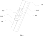
FIG 2 is an enlarged schematic diagram of part A inFIG 1 . -
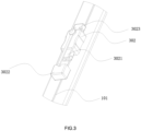
FIG 3 is a schematic structural diagram of the shelf power supply device wherein the protective cover inFIG.2 is removed. -
FIG 4 is a schematic diagram of the three-dimensional structure of the shelf power supply device with the strip-shaped power supply cavity removed of this embodiment. -
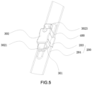
FIG 5 is an enlarged schematic diagram of part B inFIG 4 . -
FIG 6 is a schematic diagram of the structure ofFIG. 5 at another angle (front view). -
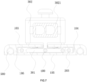
FIG 7 is a schematic cross-sectional view of the shelf power supply device of the embodiment at the power supply head. - Hereinafter, specific embodiments of the present invention will be described in further detail based on the drawings. It should be understood that the description of the embodiments of the present invention is not intended to limit the scope of protection of the present invention.
- As shown in
Figs. 1 to 7 , the shelf power supply device of this embodiment includes a strip-shapedpower supply cavity 100, a fixedpower supply terminal 200, apower supply head 300, and aflexible wire 400. - At least one set of cooperating members including a fixed
power supply terminal 200, apower supply head 300 and aflexible wire 400 is provided in the strip-shapedpower supply cavity 100, which can be set according to the number of shelves, and a corresponding strip-shaped mounting hole 101 is provided for each set. The strip-shaped mounting holes 101 on the strip-shapedpower supply cavity 100 can be connected to each other or partitioned. In this embodiment, six groups or sets, each including a fixedpower supply terminal 200, apower supply head 300 and aflexible wire 400 matched to each other, are provided in the strip-shapedpower supply cavity 100, and the strip-shaped mounting holes 101 are connected with each other. In fact, in order to facilitate production and installation, in this embodiment, the strip-shaped mounting holes 101 are connected to each other and are connected to both ends of the strip-shapedpower supply cavity 100. - The length and direction of the strip-shaped
power supply cavity 100 are set according to the power supply requirements, and can be flat or curved, and the strip-shapedpower supply cavity 100 can be surrounded by side plates. The side plates can be integral or spliced together. In order to achieve a power supply, at least one fixedpower supply terminal 200 is provided inside the strip-shapedpower supply cavity 100. The fixedpower supply terminal 200 can be positioned directly via the side plate and laterally penetrating from the side plate of the strip-shapedpower supply cavity 100 and then fixed, and then it may be externally connected to a main power supply equipment. Or a bus passing through the strip-shapedpower supply cavity 100 may be provided, apower supply block 203 may be arranged on the bus, and then thepower supply block 203 is fixed to realize the positioning of the fixedpower supply terminal 200 in the strip-shapedpower supply cavity 100. The fixedpower supply terminal 200 includes a power supply wire 204 (that is, a bus) and apower supply block 203. Thepower supply wire 204 passes through the strip-shapedpower supply cavity 100 and is fixed at both ends. Thepower supply block 203 is fixedly connected to thepower supply wire 204 and is connected to theflexible wire 400. In order to facilitate the acquisition of materials and reduce the cost, in this embodiment, thepower supply wire 204 is an insulated wire. Thepower supply wire 204 is used to connect to the power supply bus. For convenience, a connector is generally provided at the end to connect with the external power supply bus. Of course, welding can also be used to achieve electrical connection. In this embodiment, the strip-shapedpower supply cavity 100 is provided with apower supply socket 102 at one end. - The fixed
power supply terminal 200 is arranged in the strip-shapedpower supply cavity 100, and the side wall of the strip-shapedpower supply cavity 100 is provided with a strip-shaped mounting hole 101 extending along its length. Thepower supply head 300 is positioned to slide on thestrip mounting hole 101, and thepower supply head 300 includes apower supply part 301 located in the strip-shapedpower supply cavity 100 and anoutput part 302 located outside the strip-shapedpower supply cavity 100. Aflexible wire 400 is provided in the strip-shapedpower supply cavity 100, the two ends of theflexible wire 400 are respectively connected to the fixedpower supply terminal 200 and thepower supply part 301. When thepower supply head 300 is far from or close to the fixedpower supply terminal 200, theflexible wire 400 is stretched or bent in the strip-shapedpower supply cavity 100. - The strip-shaped
power supply cavity 100 is provided with at least onepower supply head 300 that can moved and positioned in the longitudinal direction of the strip-shapedpower supply cavity 100 depending on the requirements, and aflexible wire 400 is arranged in the strip-shapedpower supply cavity 100 to cooperate with the movement of thepower supply head 300 to supply power. This structure is simple, flexible to use, and suitable for changing shelf power supply. Theflexible wire 400 is suitable for the power supply of the shelf, as long as it is waterproof, for example, for example an ordinary insulated wire can be used to achieve a good waterproof effect. Theflexible wire 400 is confined in the strip-shapedpower supply cavity 100, so that it is not easy to be observed, and thus the shelf is kept neat and beautiful. - When an external electrical appliance is connected to the
output part 302, there are various power supply structures. For ease of use, theoutput part 302 is provided with a plug orsocket 3021 for external power supply. Theplug 3021 generally has a wire and is directly connected to the electrical appliance. In this embodiment, thesocket 3021 is used, which is more flexible in use. - In order to protect the
socket 3021 from dust and water, aprotective cover 3022 is provided on thesocket 3021. In order to prevent theprotective cover 3022 from being lost when thesocket 3021 is in use, in this embodiment, theoutput part 302 is provided with avirtual socket 3023 having the same shape as thesocket 3021 and matching with theprotective cover 3022. Thevirtual socket 3023 can be made into a solid structure with the same shape as thesocket 3021. - The fixed
power supply terminal 200 is divided into two groups, namely a group which is positive and a group which is negative. Correspondingly, theflexible wire 400 is divided into a positiveflexible wire 401 and a negativeflexible wire 402, which are respectively connected to the corresponding fixedpower supply terminal 200. The other end of the positiveflexible wire 401 and of the negativeflexible wire 402 is connected to the samepower supply head 300 which is associated to the fixedpower supply terminal 200. - In order to provide sufficient bending space for the two
flexible wires power supply cavity 100, the positiveflexible wire 401 and the negativeflexible wire 402 are respectively located on opposite sides of thepower supply head 300. The positive fixedpower supply terminal 201 and the negative fixedpower supply terminal 202 are arranged opposite to each other. In order to make the structure compact, in this embodiment, the projection of thepower supply head 300 on the cross section of the strip-shapedpower supply cavity 100 along the length direction of the strip-shapedpower supply cavity 100 is located between the positive fixedpower supply terminal 201 and the negative fixedpower supply terminal 202. This configuration allows for a more balanced force on thepower supply head 300, and it is not easy to get stuck. - There are many ways to achieve a positioning of the
power supply head 300. For ease of operation, thepower supply head 300 and the strip-shapedpower supply cavity 100 are positioned by friction. When the size of thepower supply head 300 is set to be in interference fit with at least a part of the inner wall of the strip-shapedpower supply cavity 100, friction positioning can be achieved. The external material of thepower supply head 300 can be made of soft rubber, silica gel, etc., to increase friction force. - The shape of the cross-section of the strip-shaped
power supply cavity 100 can be designed according to the installation position, and is limited by side plates. When it is applied to common display equipment such as shelves, the surface mount installation method is generally adopted. In order to reduce the volume and reduce installation space, in this embodiment, the strip-shapedpower supply cavity 100 is a flat rectangle with a certain width and height. The strip-shapedpower supply cavity 100 is surrounded by four side plates, afront cover 103, aleft side rail 104, arear cover 105 and aright side rail 106. Thefront cover 103, theleft side rail 104, therear cover 105, and theright side rail 106 can be manufactured and assembled using a fastener connection, glue bonding or snap connection technique. For ease of manufacturing, in this embodiment, thefront cover 103, theleft side rail 104, therear cover 105 and theright side rail 106 are integrally formed and manufactured. The manufacturing process can be realized by extrusion molding. Generally, the material can be plastic. In this embodiment, PVC is used and thefront cover 103 is provided with a strip-shaped mountinghole 101. - In order to further prevent the
flexible wire 400 from being wound and overlapping, the condition D<H<2D may apply, wherein H is the distance between the inner walls of thefront cover 103 and therear cover 105 of the strip-shapedpower supply cavity 100, and D is the diameter of theflexible wire 400. Thus, theflexible wire 400 is bent and folded in a single plane, avoiding entanglement. - In order to facilitate installation, a magnetic member may be provided on the outer side wall of the strip-shaped
power supply cavity 100. In this embodiment, the magnetic member is acylindrical magnet 500 provided on both sides of therear cover 105.
Claims (15)
- A shelf power supply device comprising a strip-shaped power supply cavity (100), a fixed power supply terminal (200) and a power supply head (300), wherein:the strip-shaped power supply cavity (100) is provided with a strip-shaped mounting hole (101) extending along the length direction of its side wall;the fixed power supply terminal (200) is arranged inside the strip-shaped power supply cavity (100);the power supply head (300) is positioned on the strip-shaped mounting hole (101), and comprises a power supply part (301) located inside the strip-shaped power supply cavity (100) and an output part (302) located outside the strip-shaped power supply cavity (100);the shelf power supply device further comprises a flexible wire (400) having two ends, whereinthe power supply head (300) is positioned to be slidable on the strip-shaped mounting hole (101) andthe flexible wire (400) is arranged inside the strip-shaped power supply cavity (100), anda first end of the flexible wire (400) is connected to the fixed power supply terminal (200) and a second end of the flexible wire (400) is connected to the power supply part (301), wherein, when the power supply head (300) is far from or close to the fixed power supply terminal (200), the flexible wire (400) is stretched or bent correspondingly in the strip-shaped power supply cavity (100),characterized in that the fixed power supply terminal (200) comprises a power supply wire (204) passing through the strip-shaped power supply cavity (100) and fixed at both ends thereof and a power supply block (203) fixedly connected to the power supply wire (204) and connected to the flexible wire (400).
- The shelf power supply device as claimed in claim 1, wherein the output part (302) of the power supply head (300) is provided with a plug or socket (3021) for external power supply.
- The shelf power supply device as claimed in claim 2, wherein a protective cover (3022) is provided on the socket (3021).
- The shelf power supply device as claimed in claim 3, wherein the output part (302) is provided with a virtual socket (3023) having the same shape as the socket (3021) and matching with the protective cover (3022).
- The shelf power supply device as claimed in any of the preceding claims, wherein the fixed power supply terminal (200) is divided into a positive fixed power supply terminal (201) and negative fixed power supply terminal (202), and correspondingly, the flexible wire (400) is divided into a positive flexible wire (401) and a negative flexible wire (402), a first end of the positive flexible wire (401) being connected to the positive fixed power supply terminal (201) and a first end of the negative flexible wire (402) being connected to the negative fixed power supply terminal (202), and a respective second end of the positive flexible wire (401) and the negative flexible wire (402) being connected to the same power supply head (300).
- The shelf power supply device as claimed in claim 5, wherein, in the length direction of the strip-shaped power supply cavity (100), the positive flexible wire (401) and the negative flexible wire (402) are respectively located on opposite sides of the power supply head (300).
- The shelf power supply device as claimed in claim 5, wherein the positive fixed power supply terminal (201) and the negative fixed power supply terminal (202) are arranged opposite to each other.
- The shelf power supply device as claimed in claim 7, wherein the projection of the power supply head (300) on the cross section of the strip-shaped power supply cavity (100) along the length direction of the strip-shaped power supply cavity (100) is located between the positive fixed power supply terminal (201) and the negative fixed power supply terminal (202).
- The shelf power supply device as claimed in any of the preceding claims, wherein the power supply head (300) and the strip-shaped power supply cavity (100) are positioned by friction.
- The shelf power supply device as claimed in claim 9, wherein a size of the power supply head (300) is matched to an inner wall of the strip-shaped power supply cavity (100) to enable an interference fit with at least a part of the inner wall of the strip-shaped power supply cavity (100).
- The shelf power supply device as claimed in claim 9 or 10, wherein an external material of the power supply head (300) is made of soft rubber or silica gel to increase friction.
- The shelf power supply device as claimed in any of the preceding claims, wherein the strip-shaped power supply cavity (100) is surrounded by four side plates, a front cover (103), a left side rail (104), a rear cover (105) and a right side rail (106).
- The shelf power supply device as claimed in claim 12, wherein the front cover (103), the left side rail (104), the rear cover (105) and the right side rail (106) are integrally formed, in particular by extrusion molding, the front cover (103) being provided with the strip-shaped mounting hole (101).
- The shelf power supply device as claimed in claim 12 or claim 13, wherein a cylindrical magnet (500) is provided on both sides of the rear cover (105) of the strip-shaped power supply cavity (100).
- The shelf power supply device as claimed in any of the preceding claims, wherein the strip-shaped power supply cavity (100) is provided with a power supply socket (102) at one end thereof, configured to connect the power supply wire (204) with an external power supply bus.
Applications Claiming Priority (2)
| Application Number | Priority Date | Filing Date | Title |
|---|---|---|---|
| CN202010006938.XA CN111082270B (en) | 2020-01-03 | 2020-01-03 | A shelf power supply device |
| PCT/EP2020/077331 WO2021136606A1 (en) | 2020-01-03 | 2020-09-30 | Shelf power supply device |
Publications (3)
| Publication Number | Publication Date |
|---|---|
| EP4046244A1 EP4046244A1 (en) | 2022-08-24 |
| EP4046244C0 EP4046244C0 (en) | 2024-05-01 |
| EP4046244B1 true EP4046244B1 (en) | 2024-05-01 |
Family
ID=70321900
Family Applications (1)
| Application Number | Title | Priority Date | Filing Date |
|---|---|---|---|
| EP20785725.1A Active EP4046244B1 (en) | 2020-01-03 | 2020-09-30 | Shelf power supply device |
Country Status (4)
| Country | Link |
|---|---|
| EP (1) | EP4046244B1 (en) |
| CN (1) | CN111082270B (en) |
| DE (1) | DE202020006015U1 (en) |
| WO (1) | WO2021136606A1 (en) |
Families Citing this family (2)
| Publication number | Priority date | Publication date | Assignee | Title |
|---|---|---|---|---|
| CN214411705U (en) * | 2020-09-27 | 2021-10-15 | 赛尔富电子有限公司 | Waterproof power supply track |
| CN113708135B (en) * | 2021-04-22 | 2024-07-09 | 赛尔富电子有限公司 | Waterproof power supply rail |
Citations (1)
| Publication number | Priority date | Publication date | Assignee | Title |
|---|---|---|---|---|
| US1606870A (en) * | 1925-03-18 | 1926-11-16 | Harley G Corwin | Adjustable electric fixture with concealed wiring |
Family Cites Families (22)
| Publication number | Priority date | Publication date | Assignee | Title |
|---|---|---|---|---|
| GB1483337A (en) * | 1974-07-30 | 1977-08-17 | Baskeyfield M | Domestic/commercial electrical outlet system |
| DE8816654U1 (en) * | 1988-01-14 | 1990-03-29 | Demmer, Matthias, 5000 Köln | Low-voltage luminaire for cable systems |
| US5183406A (en) * | 1990-03-27 | 1993-02-02 | Glen Bryan D | Baseboard with movable electrical outlet |
| US5306165A (en) * | 1993-01-27 | 1994-04-26 | Jacques Nadeau | Electric distributing system |
| US6350135B1 (en) * | 1999-07-29 | 2002-02-26 | University Of Rochester | Power outlet for divided channel raceway |
| US7513675B2 (en) * | 2004-05-06 | 2009-04-07 | Genlyte Thomas Group Llc | Modular luminaire system with track and ballast attachment means |
| CN201059503Y (en) * | 2007-07-05 | 2008-05-14 | 鹤山丽得电子实业有限公司 | Novel low pressure LED railway lamp |
| US9228732B2 (en) * | 2008-07-08 | 2016-01-05 | Us Vaopto, Inc. | Modular LED lighting systems, including flexible, rigid, and waterproof lighting strips and connectors |
| CN201570678U (en) * | 2009-11-27 | 2010-09-01 | 英业达股份有限公司 | movable socket |
| CN103066459A (en) * | 2011-10-20 | 2013-04-24 | 鸿富锦精密工业(深圳)有限公司 | Rotary socket |
| RU2695294C2 (en) * | 2012-10-31 | 2019-07-22 | Медиа Граф Дипот Инк. | Lighting system |
| KR20170010711A (en) * | 2014-05-29 | 2017-02-01 | 루이즈 페르난도 데스트로 | Arrangement for Energized Rail for Movable Sockets |
| ES2637562B1 (en) * | 2016-04-12 | 2018-02-07 | Fabricación De Material Eléctrico, S.A. | MODULE FOR SLIDING POWER OUTLET |
| CN205811207U (en) * | 2016-06-22 | 2016-12-14 | 赛尔富电子有限公司 | A kind of stand alone type electricity getting device and use the shelf of this electricity getting device |
| CN116154696A (en) * | 2017-11-01 | 2023-05-23 | 无锡蜜蜂照明科技有限公司 | A rack built-in power-taking system |
| CN207910196U (en) * | 2018-01-27 | 2018-09-25 | 廖占峰 | A kind of arrangements of electric connection |
| CN109921243A (en) * | 2019-03-04 | 2019-06-21 | 西北工业大学 | A kind of movable socket |
| CN110307531A (en) * | 2019-06-21 | 2019-10-08 | 赛尔富电子有限公司 | A retractable cable manager |
| CN110492285B (en) * | 2019-07-12 | 2024-10-01 | 赛尔富电子有限公司 | Goods shelf power supply system |
| CN110854633A (en) * | 2019-10-22 | 2020-02-28 | 赛尔富电子有限公司 | Power supply device for display and exhibition |
| CN211859097U (en) * | 2019-10-22 | 2020-11-03 | 赛尔富电子有限公司 | Power supply device for display and exhibition |
| CN211719913U (en) * | 2020-01-03 | 2020-10-20 | 赛尔富电子有限公司 | Goods shelf power supply device |
-
2020
- 2020-01-03 CN CN202010006938.XA patent/CN111082270B/en active Active
- 2020-09-30 DE DE202020006015.1U patent/DE202020006015U1/en active Active
- 2020-09-30 WO PCT/EP2020/077331 patent/WO2021136606A1/en not_active Ceased
- 2020-09-30 EP EP20785725.1A patent/EP4046244B1/en active Active
Patent Citations (1)
| Publication number | Priority date | Publication date | Assignee | Title |
|---|---|---|---|---|
| US1606870A (en) * | 1925-03-18 | 1926-11-16 | Harley G Corwin | Adjustable electric fixture with concealed wiring |
Also Published As
| Publication number | Publication date |
|---|---|
| EP4046244C0 (en) | 2024-05-01 |
| EP4046244A1 (en) | 2022-08-24 |
| CN111082270B (en) | 2025-02-18 |
| WO2021136606A1 (en) | 2021-07-08 |
| DE202020006015U1 (en) | 2024-04-02 |
| CN111082270A (en) | 2020-04-28 |
Similar Documents
| Publication | Publication Date | Title |
|---|---|---|
| US11528991B2 (en) | Shelf power supply system | |
| US9782018B2 (en) | Modular wall assembly for a cosmetic fixture system | |
| US7824185B2 (en) | Outlet device with changeable position features | |
| US3763307A (en) | Electrical strip cable assembly | |
| EP3772245B1 (en) | Telescopic power supply track | |
| CN110854633A (en) | Power supply device for display and exhibition | |
| EP4046244A1 (en) | Shelf power supply device | |
| WO2021239150A1 (en) | Track lighting system | |
| WO2022165766A1 (en) | Led unit board and display screen | |
| US20060012977A1 (en) | Slatwall lighting system | |
| CN212064298U (en) | Intelligent sound post capable of adjusting direction | |
| CN211719913U (en) | Goods shelf power supply device | |
| CN111536449A (en) | Track lamp assembly | |
| EP3754794B1 (en) | Telescopic power supply track | |
| CN108199242A (en) | A kind of built-in tracks electricity getting device | |
| EP4198386B1 (en) | Lighting system with a continuous flexible track | |
| CA2984651C (en) | Laterally supported lights | |
| EP1602098A1 (en) | Illuminated foldable module and display system | |
| KR20010016731A (en) | Distributing duct having external connection grooves | |
| GB2101175A (en) | Screen | |
| CN219458217U (en) | Panel structure with LED indicator lamp | |
| CN210050761U (en) | Guide rail strip for realizing plane installation | |
| CN215488973U (en) | Hanger rail system for omnibearing display of multiple display screens | |
| CN222513992U (en) | A high efficiency strip driver | |
| CN217082882U (en) | Air conditioner maintenance board |
Legal Events
| Date | Code | Title | Description |
|---|---|---|---|
| REG | Reference to a national code |
Ref country code: DE Ref legal event code: R138 Ref document number: 202020006015 Country of ref document: DE Free format text: GERMAN DOCUMENT NUMBER IS 602020030260 |
|
| STAA | Information on the status of an ep patent application or granted ep patent |
Free format text: STATUS: UNKNOWN |
|
| STAA | Information on the status of an ep patent application or granted ep patent |
Free format text: STATUS: THE INTERNATIONAL PUBLICATION HAS BEEN MADE |
|
| PUAI | Public reference made under article 153(3) epc to a published international application that has entered the european phase |
Free format text: ORIGINAL CODE: 0009012 |
|
| STAA | Information on the status of an ep patent application or granted ep patent |
Free format text: STATUS: REQUEST FOR EXAMINATION WAS MADE |
|
| 17P | Request for examination filed |
Effective date: 20220511 |
|
| AK | Designated contracting states |
Kind code of ref document: A1 Designated state(s): AL AT BE BG CH CY CZ DE DK EE ES FI FR GB GR HR HU IE IS IT LI LT LU LV MC MK MT NL NO PL PT RO RS SE SI SK SM TR |
|
| STAA | Information on the status of an ep patent application or granted ep patent |
Free format text: STATUS: EXAMINATION IS IN PROGRESS |
|
| 17Q | First examination report despatched |
Effective date: 20221027 |
|
| DAV | Request for validation of the european patent (deleted) | ||
| DAX | Request for extension of the european patent (deleted) | ||
| GRAP | Despatch of communication of intention to grant a patent |
Free format text: ORIGINAL CODE: EPIDOSNIGR1 |
|
| STAA | Information on the status of an ep patent application or granted ep patent |
Free format text: STATUS: GRANT OF PATENT IS INTENDED |
|
| GRAS | Grant fee paid |
Free format text: ORIGINAL CODE: EPIDOSNIGR3 |
|
| RIC1 | Information provided on ipc code assigned before grant |
Ipc: A47F 3/00 20060101ALI20240222BHEP Ipc: H01R 25/16 20060101AFI20240222BHEP |
|
| GRAA | (expected) grant |
Free format text: ORIGINAL CODE: 0009210 |
|
| STAA | Information on the status of an ep patent application or granted ep patent |
Free format text: STATUS: THE PATENT HAS BEEN GRANTED |
|
| INTG | Intention to grant announced |
Effective date: 20240306 |
|
| AK | Designated contracting states |
Kind code of ref document: B1 Designated state(s): AL AT BE BG CH CY CZ DE DK EE ES FI FR GB GR HR HU IE IS IT LI LT LU LV MC MK MT NL NO PL PT RO RS SE SI SK SM TR |
|
| REG | Reference to a national code |
Ref country code: GB Ref legal event code: FG4D |
|
| REG | Reference to a national code |
Ref country code: CH Ref legal event code: EP |
|
| REG | Reference to a national code |
Ref country code: IE Ref legal event code: FG4D |
|
| REG | Reference to a national code |
Ref country code: DE Ref legal event code: R096 Ref document number: 602020030260 Country of ref document: DE |
|
| U01 | Request for unitary effect filed |
Effective date: 20240511 |
|
| U07 | Unitary effect registered |
Designated state(s): AT BE BG DE DK EE FI FR IT LT LU LV MT NL PT SE SI Effective date: 20240523 |
|
| PG25 | Lapsed in a contracting state [announced via postgrant information from national office to epo] |
Ref country code: IS Free format text: LAPSE BECAUSE OF FAILURE TO SUBMIT A TRANSLATION OF THE DESCRIPTION OR TO PAY THE FEE WITHIN THE PRESCRIBED TIME-LIMIT Effective date: 20240901 |
|
| PG25 | Lapsed in a contracting state [announced via postgrant information from national office to epo] |
Ref country code: HR Free format text: LAPSE BECAUSE OF FAILURE TO SUBMIT A TRANSLATION OF THE DESCRIPTION OR TO PAY THE FEE WITHIN THE PRESCRIBED TIME-LIMIT Effective date: 20240501 |
|
| PG25 | Lapsed in a contracting state [announced via postgrant information from national office to epo] |
Ref country code: GR Free format text: LAPSE BECAUSE OF FAILURE TO SUBMIT A TRANSLATION OF THE DESCRIPTION OR TO PAY THE FEE WITHIN THE PRESCRIBED TIME-LIMIT Effective date: 20240802 |
|
| PG25 | Lapsed in a contracting state [announced via postgrant information from national office to epo] |
Ref country code: ES Free format text: LAPSE BECAUSE OF FAILURE TO SUBMIT A TRANSLATION OF THE DESCRIPTION OR TO PAY THE FEE WITHIN THE PRESCRIBED TIME-LIMIT Effective date: 20240501 |
|
| PG25 | Lapsed in a contracting state [announced via postgrant information from national office to epo] |
Ref country code: PL Free format text: LAPSE BECAUSE OF FAILURE TO SUBMIT A TRANSLATION OF THE DESCRIPTION OR TO PAY THE FEE WITHIN THE PRESCRIBED TIME-LIMIT Effective date: 20240501 |
|
| PG25 | Lapsed in a contracting state [announced via postgrant information from national office to epo] |
Ref country code: PL Free format text: LAPSE BECAUSE OF FAILURE TO SUBMIT A TRANSLATION OF THE DESCRIPTION OR TO PAY THE FEE WITHIN THE PRESCRIBED TIME-LIMIT Effective date: 20240501 Ref country code: NO Free format text: LAPSE BECAUSE OF FAILURE TO SUBMIT A TRANSLATION OF THE DESCRIPTION OR TO PAY THE FEE WITHIN THE PRESCRIBED TIME-LIMIT Effective date: 20240801 Ref country code: IS Free format text: LAPSE BECAUSE OF FAILURE TO SUBMIT A TRANSLATION OF THE DESCRIPTION OR TO PAY THE FEE WITHIN THE PRESCRIBED TIME-LIMIT Effective date: 20240901 Ref country code: HR Free format text: LAPSE BECAUSE OF FAILURE TO SUBMIT A TRANSLATION OF THE DESCRIPTION OR TO PAY THE FEE WITHIN THE PRESCRIBED TIME-LIMIT Effective date: 20240501 Ref country code: GR Free format text: LAPSE BECAUSE OF FAILURE TO SUBMIT A TRANSLATION OF THE DESCRIPTION OR TO PAY THE FEE WITHIN THE PRESCRIBED TIME-LIMIT Effective date: 20240802 Ref country code: ES Free format text: LAPSE BECAUSE OF FAILURE TO SUBMIT A TRANSLATION OF THE DESCRIPTION OR TO PAY THE FEE WITHIN THE PRESCRIBED TIME-LIMIT Effective date: 20240501 Ref country code: RS Free format text: LAPSE BECAUSE OF FAILURE TO SUBMIT A TRANSLATION OF THE DESCRIPTION OR TO PAY THE FEE WITHIN THE PRESCRIBED TIME-LIMIT Effective date: 20240801 |
|
| U20 | Renewal fee for the european patent with unitary effect paid |
Year of fee payment: 5 Effective date: 20240930 |
|
| PG25 | Lapsed in a contracting state [announced via postgrant information from national office to epo] |
Ref country code: CZ Free format text: LAPSE BECAUSE OF FAILURE TO SUBMIT A TRANSLATION OF THE DESCRIPTION OR TO PAY THE FEE WITHIN THE PRESCRIBED TIME-LIMIT Effective date: 20240501 |
|
| PG25 | Lapsed in a contracting state [announced via postgrant information from national office to epo] |
Ref country code: RO Free format text: LAPSE BECAUSE OF FAILURE TO SUBMIT A TRANSLATION OF THE DESCRIPTION OR TO PAY THE FEE WITHIN THE PRESCRIBED TIME-LIMIT Effective date: 20240501 Ref country code: SK Free format text: LAPSE BECAUSE OF FAILURE TO SUBMIT A TRANSLATION OF THE DESCRIPTION OR TO PAY THE FEE WITHIN THE PRESCRIBED TIME-LIMIT Effective date: 20240501 |
|
| PG25 | Lapsed in a contracting state [announced via postgrant information from national office to epo] |
Ref country code: SM Free format text: LAPSE BECAUSE OF FAILURE TO SUBMIT A TRANSLATION OF THE DESCRIPTION OR TO PAY THE FEE WITHIN THE PRESCRIBED TIME-LIMIT Effective date: 20240501 |
|
| PG25 | Lapsed in a contracting state [announced via postgrant information from national office to epo] |
Ref country code: SM Free format text: LAPSE BECAUSE OF FAILURE TO SUBMIT A TRANSLATION OF THE DESCRIPTION OR TO PAY THE FEE WITHIN THE PRESCRIBED TIME-LIMIT Effective date: 20240501 Ref country code: SK Free format text: LAPSE BECAUSE OF FAILURE TO SUBMIT A TRANSLATION OF THE DESCRIPTION OR TO PAY THE FEE WITHIN THE PRESCRIBED TIME-LIMIT Effective date: 20240501 Ref country code: RO Free format text: LAPSE BECAUSE OF FAILURE TO SUBMIT A TRANSLATION OF THE DESCRIPTION OR TO PAY THE FEE WITHIN THE PRESCRIBED TIME-LIMIT Effective date: 20240501 Ref country code: CZ Free format text: LAPSE BECAUSE OF FAILURE TO SUBMIT A TRANSLATION OF THE DESCRIPTION OR TO PAY THE FEE WITHIN THE PRESCRIBED TIME-LIMIT Effective date: 20240501 |
|
| REG | Reference to a national code |
Ref country code: DE Ref legal event code: R097 Ref document number: 602020030260 Country of ref document: DE |
|
| PLBE | No opposition filed within time limit |
Free format text: ORIGINAL CODE: 0009261 |
|
| STAA | Information on the status of an ep patent application or granted ep patent |
Free format text: STATUS: NO OPPOSITION FILED WITHIN TIME LIMIT |
|
| 26N | No opposition filed |
Effective date: 20250204 |
|
| PG25 | Lapsed in a contracting state [announced via postgrant information from national office to epo] |
Ref country code: MC Free format text: LAPSE BECAUSE OF FAILURE TO SUBMIT A TRANSLATION OF THE DESCRIPTION OR TO PAY THE FEE WITHIN THE PRESCRIBED TIME-LIMIT Effective date: 20240501 |
|
| REG | Reference to a national code |
Ref country code: CH Ref legal event code: PL |
|
| GBPC | Gb: european patent ceased through non-payment of renewal fee |
Effective date: 20240930 |
|
| PG25 | Lapsed in a contracting state [announced via postgrant information from national office to epo] |
Ref country code: GB Free format text: LAPSE BECAUSE OF NON-PAYMENT OF DUE FEES Effective date: 20240930 |
|
| PG25 | Lapsed in a contracting state [announced via postgrant information from national office to epo] |
Ref country code: CH Free format text: LAPSE BECAUSE OF NON-PAYMENT OF DUE FEES Effective date: 20240930 |
|
| PG25 | Lapsed in a contracting state [announced via postgrant information from national office to epo] |
Ref country code: IE Free format text: LAPSE BECAUSE OF NON-PAYMENT OF DUE FEES Effective date: 20240930 |
|
| U20 | Renewal fee for the european patent with unitary effect paid |
Year of fee payment: 6 Effective date: 20250930 |
|
| PG25 | Lapsed in a contracting state [announced via postgrant information from national office to epo] |
Ref country code: CY Free format text: LAPSE BECAUSE OF FAILURE TO SUBMIT A TRANSLATION OF THE DESCRIPTION OR TO PAY THE FEE WITHIN THE PRESCRIBED TIME-LIMIT; INVALID AB INITIO Effective date: 20200930 |
|
| PG25 | Lapsed in a contracting state [announced via postgrant information from national office to epo] |
Ref country code: HU Free format text: LAPSE BECAUSE OF FAILURE TO SUBMIT A TRANSLATION OF THE DESCRIPTION OR TO PAY THE FEE WITHIN THE PRESCRIBED TIME-LIMIT; INVALID AB INITIO Effective date: 20200930 |