EP4045396B1 - Vitrage monte sur une structure par des points de fixation dont un au moins est exempt de jeu par rapport au vitrage ou a un cadre de pincement de celui-ci - Google Patents
Vitrage monte sur une structure par des points de fixation dont un au moins est exempt de jeu par rapport au vitrage ou a un cadre de pincement de celui-ci Download PDFInfo
- Publication number
- EP4045396B1 EP4045396B1 EP20790263.6A EP20790263A EP4045396B1 EP 4045396 B1 EP4045396 B1 EP 4045396B1 EP 20790263 A EP20790263 A EP 20790263A EP 4045396 B1 EP4045396 B1 EP 4045396B1
- Authority
- EP
- European Patent Office
- Prior art keywords
- glazing
- pin
- bushing
- assembly according
- frame
- Prior art date
- Legal status (The legal status is an assumption and is not a legal conclusion. Google has not performed a legal analysis and makes no representation as to the accuracy of the status listed.)
- Active
Links
Images
Classifications
-
- B—PERFORMING OPERATIONS; TRANSPORTING
- B64—AIRCRAFT; AVIATION; COSMONAUTICS
- B64C—AEROPLANES; HELICOPTERS
- B64C1/00—Fuselages; Constructional features common to fuselages, wings, stabilising surfaces or the like
- B64C1/14—Windows; Doors; Hatch covers or access panels; Surrounding frame structures; Canopies; Windscreens accessories therefor, e.g. pressure sensors, water deflectors, hinges, seals, handles, latches, windscreen wipers
- B64C1/1476—Canopies; Windscreens or similar transparent elements
- B64C1/1492—Structure and mounting of the transparent elements in the window or windscreen
-
- B—PERFORMING OPERATIONS; TRANSPORTING
- B60—VEHICLES IN GENERAL
- B60J—WINDOWS, WINDSCREENS, NON-FIXED ROOFS, DOORS, OR SIMILAR DEVICES FOR VEHICLES; REMOVABLE EXTERNAL PROTECTIVE COVERINGS SPECIALLY ADAPTED FOR VEHICLES
- B60J1/00—Windows; Windscreens; Accessories therefor
- B60J1/004—Mounting of windows
-
- E—FIXED CONSTRUCTIONS
- E06—DOORS, WINDOWS, SHUTTERS, OR ROLLER BLINDS IN GENERAL; LADDERS
- E06B—FIXED OR MOVABLE CLOSURES FOR OPENINGS IN BUILDINGS, VEHICLES, FENCES OR LIKE ENCLOSURES IN GENERAL, e.g. DOORS, WINDOWS, BLINDS, GATES
- E06B3/00—Window sashes, door leaves, or like elements for closing wall or like openings; Layout of fixed or moving closures, e.g. windows in wall or like openings; Features of rigidly-mounted outer frames relating to the mounting of wing frames
- E06B3/54—Fixing of glass panes or like plates
- E06B3/5481—Fixing of glass panes or like plates by means of discrete fixing elements, e.g. glazing clips, glaziers points
Definitions
- the invention relates to the field of bolted glazing of vehicles (land, water or air) subjected to pressures (static or dynamic) that may present a risk of buckling.
- a static pressure here refers to a pressure exerted on the outer face of the glazing of an aircraft, for example, at a constant non-zero speed, and a dynamic pressure to a pressure exerted on the outer face of the glazing of an aircraft whose speed varies.
- Buckling is defined as a reversal of the curvature of the glazing, generally towards the inside (or the cabin) of the aircraft under the effect of a load such as aerodynamic pressure. Since the aerodynamic pressures from the outside to the inside are low, less than 0.1 bar, compared to the cabin pressurization level greater than 0.6 bar, the buckling phenomenon does not concern pressurized aircraft glazing.
- the glazing is bolted directly or via a glazing clamping frame, on or through the mounting structure (aircraft fuselage, etc.) so as to keep the glazing attached to it.
- the screws hold the glazing against the structure.
- the translational stop of the glazing is done by friction (under the screw head), and the swiveling stresses the body of the screw itself.
- the possibilities are to thicken the transparency and/or the frame to increase the stiffness of the glazing, and/or to multiply the number of fixing points to stiffen the boundary conditions.
- the invention consists in defining specific fixing points (rigid fixing), combining the function traditional support for the glazing on the structure with anti-translation and anti-rotation functions to locally stiffen the boundary conditions.
- Monolithic glazing consists of a single transparent sheet of mineral glass such as soda-lime, aluminosilicate, borosilicate, etc., possibly thermally toughened or chemically reinforced, or of polymer material such as poly(methyl methacrylate) (PMMA), polycarbonate (PC), polyurethane (PU), ionomer resin, etc.
- PMMA poly(methyl methacrylate)
- PC polycarbonate
- PU polyurethane
- ionomer resin etc.
- Laminated glazing is made up of several such transparent sheets of mineral glass or polymer material glued two by two by an interlayer adhesive layer of polyvinyl butyral (PVB), thermoplastic polyurethane (TPU), ethylene-vinyl acetate (EVA)..
- PVB polyvinyl butyral
- TPU thermoplastic polyurethane
- EVA ethylene-vinyl acetate
- a socket When a socket is used, it is inserted without clearance into a corresponding hole in the glazing or in the clamping frame thereof.
- the screw of a bolt concentric with the socket can be inserted into it, or on the contrary, the socket is independent of any screw, of any screw-nut assembly (bolt).
- the socket like the pin, is also inserted without clearance into a corresponding hole in the mounting structure, possibly passing through the structure.
- Rigid fixing points are specially defined (quantity and position) according to the parameters of the use case (dimension/shape/thickness of the glazing, structural rigidity, pressure distribution, materials used, etc.) to avoid any hyper-staticity and maintain the assembly of the product without constraints.
- the number of sockets and pins, the passage of a screw or not in a socket, the shapes of the sockets and pins used (seen in more detail below), the presence or absence of a shoulder on the sockets/pins, and the joint use of different sockets and/or pins will also be adapted according to these parameters of the use case.
- the rigid fixing points according to the invention are of interest for glazing subjected to pressures likely to cause buckling and for which it is desired to limit the mass and/or facilitate implementation, assembly and/or replacement.
- the invention makes it possible, by combining a few rigid fixing points in the less stiff parts of the periphery of the glazing, where buckling is likely to occur, with known fixing points, with play, to reduce the total number of fixing points of the glazing without modifying its behavior with respect to buckling, or to maintain the total number of fixing points while reducing or eliminating buckling.
- said sleeve or said pin is made of a mechanically resistant rigid material such as metallic or composite comprising fillers and/or reinforcing fibers.
- At least one socket has a cylindrical tube section geometry.
- At least one pawn is cylindrical and solid.
- At least one pawn is conical and solid.
- At least one socket or at least one pin has a shoulder, in particular for support and stopping against the surface of said structure.
- Another object of the invention consists in the application of an assembly as defined in claims 1 to 5, in which the glazing is subjected to static or dynamic pressures, in particular in which the glazing is a aeronautical glazing, in particular airplane or helicopter glazing.
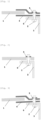
- an aircraft window 1 is clamped by a frame 4 bolted to a structure 3 (fuse) by means of a bolt 2 consisting of a screw and a nut.
- a washer 5 separates the screw head from the upper half of the frame 4 for clamping the window 1.
- a water and air seal 6 separates the lower half of the frame 4 and the structure 3.
- the screw of the bolt 2 is inserted with play in the hole of the frame 4, so that the holes of the frame 4 coincide with the corresponding holes of the structure 3, until the end of the bolting, that is to say including for the bolts tightened last.
- FIG. 2 differs from the Figure 1 by the absence of an intermediate frame 4, the glazing 1 being this time itself provided with a hole and bolted directly onto and through the fuselage 3.
- the screw of the bolt 2 is, for the same reasons as in Figure 1 , inserted with play in the hole of the glazing 1.
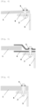
- the glazing fitted to the Figures 1 , respectively 2 are represented in buckling condition, on the Figures 3 , respectively 4.
- the translational stop is made by friction under the screw head of the frame 4, respectively of the glazing 1.
- the swiveling stresses the body of the screw itself.
- the glazing fitted with Figures 1 , respectively 2 can be modified by thickening them as shown in the Figures 5 , respectively 6.
- the resulting weight gain is clearly unfavorable, especially in an aeronautical application.
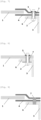
- the glazings mounted on the Figures 1 , respectively 2 have one or more (not all, generally a minority, a limited number of) modified bolting attachment points as shown in the Figures 7 , respectively 8.
- a sleeve 7 is inserted without any play into the hole of the frame 4 or the glazing 1 on the one hand, of the fuselage 3 on the other hand.
- the screw of a bolt 2 can be inserted into the sleeve 7 as shown in the Figures 7 and 8 , but may just as well not be.
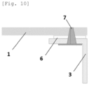
- the glazings mounted on the Figures 1 , respectively 2 have one or more (not all, generally a minority, a limited number of) modified bolting attachment points as shown in the Figure 9 , and, according to the embodiment of the invention, as shown in the Figure 10 .
- a cylindrical 7 (full) pawn, respectively conical, is inserted without any play into the hole of the frame 4, respectively of the glazing 1. The latter is therefore conical.
- Socket 7 of the Figure 8 like pawn 7 of the Figure 10 has a support and stop shoulder against the lower surface of the fuselage 3.
Landscapes
- Engineering & Computer Science (AREA)
- Mechanical Engineering (AREA)
- Aviation & Aerospace Engineering (AREA)
- Civil Engineering (AREA)
- Structural Engineering (AREA)
- Connection Of Plates (AREA)
- Securing Of Glass Panes Or The Like (AREA)
- Load-Bearing And Curtain Walls (AREA)
- Mirrors, Picture Frames, Photograph Stands, And Related Fastening Devices (AREA)
Description
- L'invention se rapporte au domaine des vitrages boulonnés de véhicules (terrestre, aquatique ou aérien) soumis à des pressions (statiques ou dynamiques) pouvant présenter un risque de flambement. Une pression statique fait ici référence à une pression exercée sur la face extérieure du vitrage d'un aéronef, par exemple, à vitesse non nulle constante, et une pression dynamique à une pression exercée sur la face extérieure du vitrage d'un aéronef dont la vitesse varie. Le flambement est défini comme une inversion de courbure du vitrage, en général vers l'intérieur (ou la cabine) de l'avion sous l'effet d'une charge telle que la pression aérodynamique. Les pressions aérodynamiques de l'extérieur vers l'intérieur étant faibles, inférieures à 0,1 bar, par rapport au niveau de pressurisation cabine supérieur à 0,6 bar, le phénomène de flambement ne concerne pas les vitrages d'aéronef pressurisé.
- Actuellement, les vitrages sont boulonnés directement ou par l'intermédiaire d'un cadre de pincement du vitrage, sur ou à travers la structure de montage (carlingue d'avion,...) de sorte à maintenir le vitrage solidaire de celle-ci. Les vis viennent maintenir en appuis le vitrage sur la structure. Les points de fixation peuvent être nombreux, par exemple d'un nombre supérieur à 80 pour un vitrage de 1,2 m2 : cela impose de monter les vis avec un jeu sur le vitrage ou le cadre de pincement de celui-ci, pour que les trous dans ce vitrage ou dans ce cadre soient en face de ceux correspondants dans la structure, pour les boulons serrés en dernier lieu.
- L'arrêt en translation du vitrage se fait par frottement (sous la tête de vis), et le rotulage sollicite le corps de la vis elle-même.
- Pour se prémunir du risque de flambement, les possibilités sont d'épaissir le transparent et/ou le cadre pour augmenter la raideur du vitrage, et/ou de multiplier le nombre de points de fixation pour rigidifier les conditions aux limites.
- Ces possibilités posent plusieurs problèmes, d'importance variable selon les domaines (terrestre / aérien), qui sont les suivants :
- augmentation importante du poids : épaissir le transparent et augmenter le nombre de fixations impacte directement le poids du vitrage ; c'est particulièrement problématique dans les applications aéronautiques ;
- augmentation du temps de montage: augmenter le nombre de fixations signifie un temps de remplacement plus long et plus coûteux (en temps et en composants) ; par ailleurs, multiplier le nombre de points de fixation augmente la complexité du serrage (ordre) et la répétabilité des conditions aux limites ;
- affaiblissement de la résistance au bord : les perçages sont des zones de concentration de contraintes importantes ; augmenter le nombre de perçages signifie augmenter les contraintes ; par ailleurs, un transparent plus épais (plus raide) transmettra davantage de contraintes aux attachements en cas de choc (oiseau, piéton, animal, projectile...) : le bord de la structure de montage et le bord du vitrage (cadre) devront être dimensionnés en conséquence (plus lourd).
- D'autre part, le document
US 2012/228428 A1 décrit un vitrage boulonné au moyen d'une douille montée sur une structure. - L'invention consiste à définir des points de fixation spécifiques (fixation rigide), combinant la fonction traditionnelle de maintien en appui du vitrage sur la structure avec des fonctions anti-translation et anti-rotulage pour rigidifier localement les conditions aux limites.
- A cet effet, l'invention est exposée dans le jeu de revendications joint.
- Un vitrage monolithique consiste en une unique feuille transparente en verre minéral tel que sodocalcique, aluminosilicate, borosilicate..., éventuellement trempée thermiquement ou renforcée chimiquement, ou en matériau polymère tel que poly(méthacrylate de méthyle) (PMMA), polycarbonate (PC), polyuréthane (PU), résine ionomère...
- Un vitrage feuilleté est constitué de plusieurs telles feuilles transparentes en verre minéral ou en matériau polymère collées deux à deux par une couche adhésive intercalaire en polyvinylbutyral (PVB), polyuréthane thermoplastique (TPU), éthylène-acétate de vinyle (EVA)...
- Quand une douille est employée, elle est insérée sans jeu dans un trou correspondant du vitrage ou du cadre de pincement de celui-ci. La vis d'un boulon concentrique à la douille peut être insérée dans celle-ci, ou au contraire, la douille est indépendante de toute vis, de tout ensemble vis-écrou (boulon). La douille, comme le pion, est également insérée sans jeu dans un trou correspondant de la structure de montage, éventuellement en traversant la structure.
- Les points de fixation rigides (sans jeu) sont spécialement définis (quantité et position) en fonction des paramètres du cas d'emploi (dimension/forme/épaisseur du vitrage, rigidité structure, répartition de la pression, matériaux mis en œuvre...) pour éviter tout hyper-statisme et conserver la montabilité du produit sans contraintes. Le nombre des douilles et pions, le passage d'une vis ou non dans une douille, les formes des douilles et pions utilisés (vues plus en détails ci-dessous), la présence ou non d'un épaulement sur les douilles/pions, et l'utilisation conjointe de douilles et/ou de pions différents seront aussi adaptés en fonction de ces paramètres du cas d'emploi.
- Les points de fixation rigides conformes à l'invention sont intéressants pour les vitrages soumis à des pressions susceptibles de provoquer du flambement et dont on souhaite limiter la masse et/ou faciliter la mise en oeuvre, le montage et/ou le remplacement.
- L'invention permet, en combinant quelques points de fixation rigides dans les parties de la périphérie du vitrage les moins raides, où le flambement est susceptible de naître, à des points de fixation connus, avec du jeu, de diminuer le nombre total de points de fixation du vitrage sans modifier son comportement vis-à-vis du flambement, ou de maintenir le nombre total de points de fixation en diminuant ou supprimant le flambement.
- De préférence, ladite douille ou ledit pion est constitué(e) d'un matériau rigide résistant mécaniquement tel que métallique ou composite comprenant des charges et/ou fibres de renforcement.
- De préférence, une douille au moins a une géométrie de section de tube cylindrique.
- De préférence, un pion au moins est cylindrique et plein.
- Conformément à l'invention, un pion au moins est conique et plein.
- De préférence, une douille au moins ou un pion au moins présente un épaulement, notamment d'appui et arrêt contre la surface de ladite structure.
- Un autre objet de l'invention consiste en l'application d'un ensemble tel que défini dans les revendications 1 à 5, dans laquelle le vitrage est soumis à des pressions statiques ou dynamiques, en particulier dans laquelle le vitrage est un vitrage aéronautique, notamment un vitrage d'avion ou d'hélicoptère.
- Les dessins annexés illustrent l'invention. Les figures sont des représentations schématiques en coupe de vitrages soumis à des pressions statiques et/ou dynamiques, notamment d'avion, montés sur une structure.
- [
Fig. 1] et [Fig. 2 ] représentent des vitrages connus au repos. - [
Fig. 3 ] et [Fig. 4 ] représentent des vitrages connus en position de flambement. - [
Fig. 5] et [Fig. 6 ] représentent un premier type connu de solution au problème du flambement. - [
Fig. 7] et [Fig. 8 ] sont des représentations partielles d'un ensemble conforme à une réalisation optionnelle. - [
Fig. 9 ] est également une représentation partielle d'un ensemble conforme à une réalisation optionnelle, tandis que [Fig. 10 ] représente la partie de l'ensemble conforme à l'invention elle-même. - En référence à la
Figure 1 , un vitrage 1 d'avion est pincé par un cadre 4 boulonné sur une structure 3 (carlingue) au moyen d'un boulon 2 constitué d'une vis et d'un écrou. Une rondelle 5 sépare la tête de vis de la moitié supérieure du cadre 4 de pincement du vitrage 1. Un joint d'étanchéité 6 à l'eau et à l'air sépare la moitié inférieure du cadre 4 et la structure 3. - Eu égard au nombre important de points de fixation par boulonnage du vitrage d'avion 1, la vis du boulon 2 est insérée avec du jeu dans le trou du cadre 4, afin que les trous du cadre 4 coïncident avec les trous correspondants de la structure 3, jusqu'à la fin du boulonnage, c'est-à-dire y compris pour les boulons serrés en dernier lieu.
- La
Figure 2 diffère de laFigure 1 par l'absence d'un cadre 4 intermédiaire, le vitrage 1 étant cette fois lui-même muni d'un trou et boulonné directement sur et à travers la carlingue 3. La vis du boulon 2 est, pour les mêmes raisons qu'à laFigure 1 , insérée avec du jeu dans le trou du vitrage 1. - Les vitrages montés des
Figures 1 , respectivement 2, sont représentés en condition de flambement, sur lesFigures 3 , respectivement 4. L'arrêt en translation se fait par frottement sous la tête de vis du cadre 4, respectivement du vitrage 1. Le rotulage sollicite le corps de la vis elle-même. - Pour limiter (diminuer, supprimer) le flambement, les vitrages montés des
Figures 1 , respectivement 2, peuvent être modifiés en les épaississant comme représenté sur lesFigures 5 , respectivement 6. L'alourdissement qui en résulte est à l'évidence défavorable, surtout dans une application aéronautique. - Conformément à une première réalisation optionnelle de l'invention, les vitrages montés des
Figures 1 , respectivement 2, ont un ou plusieurs (non la totalité, en général une minorité, un nombre limité de) points de fixation par boulonnage modifié(s) comme représenté sur lesFigures 7 , respectivement 8. Une douille 7 est insérée sans aucun jeu dans le trou du cadre 4 ou du vitrage 1 d'une part, de la carlingue 3 d'autre part. La vis d'un boulon 2 peut être insérée dans la douille 7 comme représenté sur lesFigures 7 et 8 , mais peut tout aussi bien ne pas l'être. - Selon une deuxième réalisation optionnelle de l'invention, les vitrages montés des
Figures 1 , respectivement 2, ont un ou plusieurs (non la totalité, en général une minorité, un nombre limité de) points de fixation par boulonnage modifié (s) comme représenté sur laFigure 9 , et, selon la réalisation de l'invention, comme représenté sur laFigure 10 . Un pion 7 (plein) cylindrique, respectivement conique, est inséré sans aucun jeu dans le trou du cadre 4, respectivement du vitrage 1. Ce dernier est donc conique. - La douille 7 de la
Figure 8 comme le pion 7 de laFigure 10 présente un épaulement d'appui et d'arrêt contre la surface inférieure de la carlingue 3. - Conformément à l'invention, la modification d'un nombre limité de points de fixation par boulonnage selon ces
Figures 7, 8, 9 et10 , dans les parties de la périphérie du vitrage de moindre rigidité, parties où prend naissance le flambement, suffit à diminuer/supprimer le flambement.
Claims (7)
- Ensemble constitué d'un vitrage monolithique ou feuilleté (1), d'une structure (3) et optionnellement d'un cadre (4), le vitrage (1) étant boulonné à travers la structure ou optionnellement pincé par le cadre (4) lui-même boulonné à travers la structure (3), dans lequel dans une partie au moins de la périphérie du vitrage de souplesse maximale ou de raideur minimale vis-à-vis du phénomène de flambement, ledit boulonnage est réalisé par l'insertion d'au moins un pion (7), et optionnellement au moyen d'au moins un boulon (2) inséré dans une douille (7) concentrique au boulon (2), et optionnellement par l'insertion d'au moins une douille (7), chaque douille (7) et chaque pion (7) étant monté(e) sans jeu à travers le vitrage (1) ou à travers le cadre (4), et sans jeu à travers la structure (3), au moins un dudit au moins un pion (7) étant conique et plein.
- Ensemble selon la revendication 1, caractérisé en ce que ladite au moins une douille (7) ou ledit au moins un pion (7) est constitué(e) d'un matériau rigide résistant mécaniquement tel que métallique ou composite comprenant des charges et/ou fibres de renforcement.
- Ensemble selon l'une des revendications précédentes, caractérisé en ce qu'une douille (7) au moins a une géométrie de section de tube cylindrique.
- Ensemble selon l'une des revendications précédentes, caractérisé en ce qu'un pion (7) au moins est cylindrique et plein.
- Ensemble selon l'une des revendications précédentes, caractérisé en ce qu'une douille (7) au moins ou un pion (7) au moins présente un épaulement, notamment d'appui et arrêt contre la surface de la structure (3).
- Application d'un ensemble selon l'une des revendications précédentes, dans laquelle le vitrage est soumis à des pressions statiques ou dynamiques.
- Application d'un ensemble selon la revendication 6, dans laquelle le vitrage est un vitrage aéronautique, notamment un vitrage d'avion ou d'hélicoptère.
Applications Claiming Priority (2)
| Application Number | Priority Date | Filing Date | Title |
|---|---|---|---|
| FR1911415A FR3101849B1 (fr) | 2019-10-14 | 2019-10-14 | Vitrage monté sur une structure par des points de fixation dont un au moins est exempt de jeu par rapport au vitrage ou à un cadre de pincement de celui-ci |
| PCT/EP2020/078588 WO2021074069A1 (fr) | 2019-10-14 | 2020-10-12 | Vitrage monte sur une structure par des points de fixation dont un au moins est exempt de jeu par rapport au vitrage ou a un cadre de pincement de celui-ci |
Publications (2)
| Publication Number | Publication Date |
|---|---|
| EP4045396A1 EP4045396A1 (fr) | 2022-08-24 |
| EP4045396B1 true EP4045396B1 (fr) | 2024-12-18 |
Family
ID=69743322
Family Applications (1)
| Application Number | Title | Priority Date | Filing Date |
|---|---|---|---|
| EP20790263.6A Active EP4045396B1 (fr) | 2019-10-14 | 2020-10-12 | Vitrage monte sur une structure par des points de fixation dont un au moins est exempt de jeu par rapport au vitrage ou a un cadre de pincement de celui-ci |
Country Status (10)
| Country | Link |
|---|---|
| US (1) | US12157554B2 (fr) |
| EP (1) | EP4045396B1 (fr) |
| KR (1) | KR20220079610A (fr) |
| CN (1) | CN114521182B (fr) |
| BR (1) | BR112022005310A2 (fr) |
| CA (1) | CA3152092A1 (fr) |
| ES (1) | ES3015144T3 (fr) |
| FR (1) | FR3101849B1 (fr) |
| IL (1) | IL292076A (fr) |
| WO (1) | WO2021074069A1 (fr) |
Family Cites Families (18)
| Publication number | Priority date | Publication date | Assignee | Title |
|---|---|---|---|---|
| US2834998A (en) * | 1954-01-25 | 1958-05-20 | Douglas Aircraft Co Inc | Means for mounting a frangible expanse to a vibratile support |
| US3919022A (en) * | 1974-02-21 | 1975-11-11 | Ppg Industries Inc | Window panel edge construction |
| US4893443A (en) * | 1989-01-18 | 1990-01-16 | W & W Glass Products Ltd. | Sealed double glazing unit |
| FR2697877B1 (fr) * | 1992-11-12 | 1995-01-27 | Sextant Avionique | Dispositif pour la fixation sans jeu de plaques de verre. |
| CA2097393A1 (fr) * | 1993-05-31 | 1994-12-01 | Boulos Alkhoury | Verrou pour portes et fenetres coulissantes |
| DE19642175C2 (de) * | 1996-10-12 | 2002-12-19 | Eckelt Glas Gmbh Steyr | Fenster mit einem Holzrahmen und einer Isolierglasscheibe |
| US20050188634A1 (en) * | 2003-09-30 | 2005-09-01 | Nelson Bolton | Laminate suspension system |
| JP4347777B2 (ja) * | 2004-09-22 | 2009-10-21 | 三菱電線工業株式会社 | 電波吸収パネル取付構造 |
| JP2007055502A (ja) * | 2005-08-25 | 2007-03-08 | Honda Motor Co Ltd | 車両用窓ガラスの取付構造 |
| CN107743727B (zh) * | 2006-06-07 | 2010-02-17 | 江西洪都航空工业集团有限责任公司 | 一种飞机舱盖非定向有机玻璃透明体边缘复合连接结构 |
| FR2939104B1 (fr) * | 2008-12-02 | 2010-11-12 | Airbus France | Aeronef a glaces de pare-brise interchangeables entre differents types |
| US9254907B2 (en) * | 2011-03-07 | 2016-02-09 | Ppg Industries Ohio, Inc. | Hoop load bearing aircraft transparency |
| US8851417B2 (en) * | 2012-08-07 | 2014-10-07 | United Technologies Corporation | Self-retaining shear pin for blind mount location |
| CN103291184B (zh) * | 2013-05-16 | 2016-06-01 | 一禾科技发展(上海)有限公司 | 民航飞机窗体透明件紧固结构及其紧固方法 |
| US9073620B2 (en) * | 2013-06-07 | 2015-07-07 | Honda Patents & Technologies North America, Llc | Fastening device for window |
| JP6209784B2 (ja) * | 2013-07-17 | 2017-10-11 | 特許機器株式会社 | 減震ストッパ構造並びに当該減震ストッパ構造を備えた防振架台 |
| FR3039128B1 (fr) * | 2015-07-20 | 2018-05-04 | Airbus Helicopters | Vitrage avec encadrement structurel integre pour aeronef |
| CN209467313U (zh) * | 2019-01-22 | 2019-10-08 | 江苏铁锚玻璃股份有限公司 | 螺栓连接安装形式的多功能航空透明件 |
-
2019
- 2019-10-14 FR FR1911415A patent/FR3101849B1/fr active Active
-
2020
- 2020-10-12 ES ES20790263T patent/ES3015144T3/es active Active
- 2020-10-12 CA CA3152092A patent/CA3152092A1/fr active Pending
- 2020-10-12 US US17/768,715 patent/US12157554B2/en active Active
- 2020-10-12 EP EP20790263.6A patent/EP4045396B1/fr active Active
- 2020-10-12 BR BR112022005310A patent/BR112022005310A2/pt unknown
- 2020-10-12 IL IL292076A patent/IL292076A/en unknown
- 2020-10-12 WO PCT/EP2020/078588 patent/WO2021074069A1/fr not_active Ceased
- 2020-10-12 CN CN202080071991.6A patent/CN114521182B/zh active Active
- 2020-10-12 KR KR1020227015145A patent/KR20220079610A/ko active Pending
Also Published As
| Publication number | Publication date |
|---|---|
| CA3152092A1 (fr) | 2021-04-22 |
| US12157554B2 (en) | 2024-12-03 |
| EP4045396A1 (fr) | 2022-08-24 |
| ES3015144T3 (en) | 2025-04-29 |
| WO2021074069A1 (fr) | 2021-04-22 |
| US20240228010A9 (en) | 2024-07-11 |
| KR20220079610A (ko) | 2022-06-13 |
| CN114521182B (zh) | 2025-04-11 |
| US20240132197A1 (en) | 2024-04-25 |
| FR3101849B1 (fr) | 2023-11-24 |
| CN114521182A (zh) | 2022-05-20 |
| IL292076A (en) | 2022-06-01 |
| FR3101849A1 (fr) | 2021-04-16 |
| BR112022005310A2 (pt) | 2022-06-14 |
Similar Documents
| Publication | Publication Date | Title |
|---|---|---|
| US9254907B2 (en) | Hoop load bearing aircraft transparency | |
| EP3827159B1 (fr) | Aube de turbomachine comportant un renfort structurel a adherence renforcee | |
| FR2673619A1 (fr) | Vitrage feuillete. | |
| FR3075759A1 (fr) | Partie anterieure de nacelle d'un ensemble propulsif d'aeronef comportant un element amortisseur | |
| EP4045396B1 (fr) | Vitrage monte sur une structure par des points de fixation dont un au moins est exempt de jeu par rapport au vitrage ou a un cadre de pincement de celui-ci | |
| EP3648972A1 (fr) | Suppression du bruit de decharge electrostatique par conduction entre un element metallique en gradin et le presse glace | |
| EP2554481B1 (fr) | Dispositif de liaison plus particulièrement adapté pour assurer la liaison entre une entrée d'air et une motorisation d'une nacelle d'aéronef | |
| EP2554480A2 (fr) | Dispositif de liaison plus particulièrement adapté pour assurer la liaison entre une entrée d'air et une motorisation d'une nacelle d'aéronef | |
| WO2021260311A1 (fr) | Vitrage monte sur une structure avec interposition d'un element rigidifiant a surface d'appui localisee entre le vitrage et la structure | |
| CA2486863C (fr) | Nez d'avion avec bouclier | |
| FR3039128A1 (fr) | Vitrage avec encadrement structurel integre pour aeronef | |
| EP4308452A1 (fr) | Vitrage multiple à joint de montage incorporant un élément de renfort et d'étanchéité | |
| WO2022129751A1 (fr) | Vitrage feuilleté à plusieurs panneaux, dont une zone de juxtaposition de panneaux voisins est renforcée par insertion d'un élément structurant | |
| EP4476134B1 (fr) | Ensemble vitré pour un aéronef, procédé de fabrication d'un tel ensemble vitré, et aéronef comprenant un tel ensemble vitré | |
| EP3848288B1 (fr) | Attache arriere entre un mat d'accrochage et une aile d'un aeronef | |
| FR3131710A1 (fr) | Vitrage feuilleté pincé à joint dont les fonctions d’étanchéité et de mise en position sont dissociées | |
| FR3069527A1 (fr) | Structure primaire a conception amelioree pour mat d'accrochage de moteur d'aeronef | |
| EP2554479B1 (fr) | Dispositif de liaison plus particulièrement adapté pour assurer la liaison entre une entrée d'air et une motorisation d'une nacelle d'aéronef | |
| EP3309078A1 (fr) | Nacelle d'aeronef comprenant une liaison entre un conduit d'une entree d'air et un conduit d'une motorisation | |
| EP4440830A1 (fr) | Vitrage feuilleté à élément de blocage en gradin | |
| EP3604074B1 (fr) | Procédé d'assemblage d'une structure de véhicule ferroviaire | |
| FR2944258A1 (fr) | Bequille de protection d'un carenage aerodynamique d'un aeronef, et aeronef muni d'une telle bequille | |
| WO2025088259A1 (fr) | Vitrage aeronautique travaillant en membrane a performance structurale accrue et aeronef le comprenant | |
| FR3024399A1 (fr) | Suspension de vehicule automobile a barre de torsion composite renforcee | |
| FR3024397A1 (fr) | Barre de torsion de suspension de vehicule automobile en materiau composite |
Legal Events
| Date | Code | Title | Description |
|---|---|---|---|
| STAA | Information on the status of an ep patent application or granted ep patent |
Free format text: STATUS: UNKNOWN |
|
| STAA | Information on the status of an ep patent application or granted ep patent |
Free format text: STATUS: THE INTERNATIONAL PUBLICATION HAS BEEN MADE |
|
| PUAI | Public reference made under article 153(3) epc to a published international application that has entered the european phase |
Free format text: ORIGINAL CODE: 0009012 |
|
| STAA | Information on the status of an ep patent application or granted ep patent |
Free format text: STATUS: REQUEST FOR EXAMINATION WAS MADE |
|
| 17P | Request for examination filed |
Effective date: 20220516 |
|
| AK | Designated contracting states |
Kind code of ref document: A1 Designated state(s): AL AT BE BG CH CY CZ DE DK EE ES FI FR GB GR HR HU IE IS IT LI LT LU LV MC MK MT NL NO PL PT RO RS SE SI SK SM TR |
|
| DAV | Request for validation of the european patent (deleted) | ||
| DAX | Request for extension of the european patent (deleted) | ||
| STAA | Information on the status of an ep patent application or granted ep patent |
Free format text: STATUS: EXAMINATION IS IN PROGRESS |
|
| 17Q | First examination report despatched |
Effective date: 20231030 |
|
| GRAP | Despatch of communication of intention to grant a patent |
Free format text: ORIGINAL CODE: EPIDOSNIGR1 |
|
| STAA | Information on the status of an ep patent application or granted ep patent |
Free format text: STATUS: GRANT OF PATENT IS INTENDED |
|
| GRAS | Grant fee paid |
Free format text: ORIGINAL CODE: EPIDOSNIGR3 |
|
| GRAA | (expected) grant |
Free format text: ORIGINAL CODE: 0009210 |
|
| STAA | Information on the status of an ep patent application or granted ep patent |
Free format text: STATUS: THE PATENT HAS BEEN GRANTED |
|
| INTG | Intention to grant announced |
Effective date: 20241023 |
|
| AK | Designated contracting states |
Kind code of ref document: B1 Designated state(s): AL AT BE BG CH CY CZ DE DK EE ES FI FR GB GR HR HU IE IS IT LI LT LU LV MC MK MT NL NO PL PT RO RS SE SI SK SM TR |
|
| REG | Reference to a national code |
Ref country code: CH Ref legal event code: EP |
|
| REG | Reference to a national code |
Ref country code: DE Ref legal event code: R096 Ref document number: 602020043423 Country of ref document: DE |
|
| REG | Reference to a national code |
Ref country code: IE Ref legal event code: FG4D Free format text: LANGUAGE OF EP DOCUMENT: FRENCH |
|
| P01 | Opt-out of the competence of the unified patent court (upc) registered |
Free format text: CASE NUMBER: APP_10452/2025 Effective date: 20250303 |
|
| REG | Reference to a national code |
Ref country code: LT Ref legal event code: MG9D |
|
| PG25 | Lapsed in a contracting state [announced via postgrant information from national office to epo] |
Ref country code: HR Free format text: LAPSE BECAUSE OF FAILURE TO SUBMIT A TRANSLATION OF THE DESCRIPTION OR TO PAY THE FEE WITHIN THE PRESCRIBED TIME-LIMIT Effective date: 20241218 |
|
| PG25 | Lapsed in a contracting state [announced via postgrant information from national office to epo] |
Ref country code: FI Free format text: LAPSE BECAUSE OF FAILURE TO SUBMIT A TRANSLATION OF THE DESCRIPTION OR TO PAY THE FEE WITHIN THE PRESCRIBED TIME-LIMIT Effective date: 20241218 |
|
| PG25 | Lapsed in a contracting state [announced via postgrant information from national office to epo] |
Ref country code: BG Free format text: LAPSE BECAUSE OF FAILURE TO SUBMIT A TRANSLATION OF THE DESCRIPTION OR TO PAY THE FEE WITHIN THE PRESCRIBED TIME-LIMIT Effective date: 20241218 |
|
| PG25 | Lapsed in a contracting state [announced via postgrant information from national office to epo] |
Ref country code: NO Free format text: LAPSE BECAUSE OF FAILURE TO SUBMIT A TRANSLATION OF THE DESCRIPTION OR TO PAY THE FEE WITHIN THE PRESCRIBED TIME-LIMIT Effective date: 20250318 |
|
| REG | Reference to a national code |
Ref country code: NL Ref legal event code: MP Effective date: 20241218 |
|
| PG25 | Lapsed in a contracting state [announced via postgrant information from national office to epo] |
Ref country code: GR Free format text: LAPSE BECAUSE OF FAILURE TO SUBMIT A TRANSLATION OF THE DESCRIPTION OR TO PAY THE FEE WITHIN THE PRESCRIBED TIME-LIMIT Effective date: 20250319 Ref country code: LV Free format text: LAPSE BECAUSE OF FAILURE TO SUBMIT A TRANSLATION OF THE DESCRIPTION OR TO PAY THE FEE WITHIN THE PRESCRIBED TIME-LIMIT Effective date: 20241218 |
|
| PG25 | Lapsed in a contracting state [announced via postgrant information from national office to epo] |
Ref country code: RS Free format text: LAPSE BECAUSE OF FAILURE TO SUBMIT A TRANSLATION OF THE DESCRIPTION OR TO PAY THE FEE WITHIN THE PRESCRIBED TIME-LIMIT Effective date: 20250318 |
|
| REG | Reference to a national code |
Ref country code: ES Ref legal event code: FG2A Ref document number: 3015144 Country of ref document: ES Kind code of ref document: T3 Effective date: 20250429 |
|
| PG25 | Lapsed in a contracting state [announced via postgrant information from national office to epo] |
Ref country code: NL Free format text: LAPSE BECAUSE OF FAILURE TO SUBMIT A TRANSLATION OF THE DESCRIPTION OR TO PAY THE FEE WITHIN THE PRESCRIBED TIME-LIMIT Effective date: 20241218 |
|
| REG | Reference to a national code |
Ref country code: AT Ref legal event code: MK05 Ref document number: 1752057 Country of ref document: AT Kind code of ref document: T Effective date: 20241218 |
|
| REG | Reference to a national code |
Ref country code: GB Ref legal event code: 732E Free format text: REGISTERED BETWEEN 20250515 AND 20250521 |
|
| RAP2 | Party data changed (patent owner data changed or rights of a patent transferred) |
Owner name: SAINT-GOBAIN SULLY |
|
| PG25 | Lapsed in a contracting state [announced via postgrant information from national office to epo] |
Ref country code: SM Free format text: LAPSE BECAUSE OF FAILURE TO SUBMIT A TRANSLATION OF THE DESCRIPTION OR TO PAY THE FEE WITHIN THE PRESCRIBED TIME-LIMIT Effective date: 20241218 |
|
| PG25 | Lapsed in a contracting state [announced via postgrant information from national office to epo] |
Ref country code: PL Free format text: LAPSE BECAUSE OF FAILURE TO SUBMIT A TRANSLATION OF THE DESCRIPTION OR TO PAY THE FEE WITHIN THE PRESCRIBED TIME-LIMIT Effective date: 20241218 |
|
| PG25 | Lapsed in a contracting state [announced via postgrant information from national office to epo] |
Ref country code: IS Free format text: LAPSE BECAUSE OF FAILURE TO SUBMIT A TRANSLATION OF THE DESCRIPTION OR TO PAY THE FEE WITHIN THE PRESCRIBED TIME-LIMIT Effective date: 20250418 |
|
| PG25 | Lapsed in a contracting state [announced via postgrant information from national office to epo] |
Ref country code: PT Free format text: LAPSE BECAUSE OF FAILURE TO SUBMIT A TRANSLATION OF THE DESCRIPTION OR TO PAY THE FEE WITHIN THE PRESCRIBED TIME-LIMIT Effective date: 20250421 |
|
| PG25 | Lapsed in a contracting state [announced via postgrant information from national office to epo] |
Ref country code: EE Free format text: LAPSE BECAUSE OF FAILURE TO SUBMIT A TRANSLATION OF THE DESCRIPTION OR TO PAY THE FEE WITHIN THE PRESCRIBED TIME-LIMIT Effective date: 20241218 |
|
| PG25 | Lapsed in a contracting state [announced via postgrant information from national office to epo] |
Ref country code: RO Free format text: LAPSE BECAUSE OF FAILURE TO SUBMIT A TRANSLATION OF THE DESCRIPTION OR TO PAY THE FEE WITHIN THE PRESCRIBED TIME-LIMIT Effective date: 20241218 Ref country code: AT Free format text: LAPSE BECAUSE OF FAILURE TO SUBMIT A TRANSLATION OF THE DESCRIPTION OR TO PAY THE FEE WITHIN THE PRESCRIBED TIME-LIMIT Effective date: 20241218 |
|
| PG25 | Lapsed in a contracting state [announced via postgrant information from national office to epo] |
Ref country code: SK Free format text: LAPSE BECAUSE OF FAILURE TO SUBMIT A TRANSLATION OF THE DESCRIPTION OR TO PAY THE FEE WITHIN THE PRESCRIBED TIME-LIMIT Effective date: 20241218 |
|
| PG25 | Lapsed in a contracting state [announced via postgrant information from national office to epo] |
Ref country code: CZ Free format text: LAPSE BECAUSE OF FAILURE TO SUBMIT A TRANSLATION OF THE DESCRIPTION OR TO PAY THE FEE WITHIN THE PRESCRIBED TIME-LIMIT Effective date: 20241218 |
|
| PG25 | Lapsed in a contracting state [announced via postgrant information from national office to epo] |
Ref country code: SE Free format text: LAPSE BECAUSE OF FAILURE TO SUBMIT A TRANSLATION OF THE DESCRIPTION OR TO PAY THE FEE WITHIN THE PRESCRIBED TIME-LIMIT Effective date: 20241218 |
|
| REG | Reference to a national code |
Ref country code: DE Ref legal event code: R097 Ref document number: 602020043423 Country of ref document: DE |
|
| PG25 | Lapsed in a contracting state [announced via postgrant information from national office to epo] |
Ref country code: DK Free format text: LAPSE BECAUSE OF FAILURE TO SUBMIT A TRANSLATION OF THE DESCRIPTION OR TO PAY THE FEE WITHIN THE PRESCRIBED TIME-LIMIT Effective date: 20241218 |
|
| PGFP | Annual fee paid to national office [announced via postgrant information from national office to epo] |
Ref country code: IT Payment date: 20250922 Year of fee payment: 6 |
|
| PGFP | Annual fee paid to national office [announced via postgrant information from national office to epo] |
Ref country code: FR Payment date: 20250908 Year of fee payment: 6 |
|
| REG | Reference to a national code |
Ref country code: DE Ref legal event code: R081 Ref document number: 602020043423 Country of ref document: DE Owner name: SAINT-GOBAIN SULLY, FR Free format text: FORMER OWNER: SAINT-GOBAIN GLASS FRANCE, COURBEVOIE, FR |
|
| PLBE | No opposition filed within time limit |
Free format text: ORIGINAL CODE: 0009261 |
|
| STAA | Information on the status of an ep patent application or granted ep patent |
Free format text: STATUS: NO OPPOSITION FILED WITHIN TIME LIMIT |
|
| REG | Reference to a national code |
Ref country code: CH Ref legal event code: L10 Free format text: ST27 STATUS EVENT CODE: U-0-0-L10-L00 (AS PROVIDED BY THE NATIONAL OFFICE) Effective date: 20251029 |
|
| REG | Reference to a national code |
Ref country code: CH Ref legal event code: U11 Free format text: ST27 STATUS EVENT CODE: U-0-0-U10-U11 (AS PROVIDED BY THE NATIONAL OFFICE) Effective date: 20251101 |
|
| REG | Reference to a national code |
Ref country code: ES Ref legal event code: PC2A Owner name: SAINT-GOBAIN SULLY Effective date: 20251111 |
|
| 26N | No opposition filed |
Effective date: 20250919 |
|
| PGFP | Annual fee paid to national office [announced via postgrant information from national office to epo] |
Ref country code: DE Payment date: 20250902 Year of fee payment: 6 |
|
| PGFP | Annual fee paid to national office [announced via postgrant information from national office to epo] |
Ref country code: CH Payment date: 20251101 Year of fee payment: 6 |