EP4044869B1 - Telescopic guide for drawer - Google Patents
Telescopic guide for drawer Download PDFInfo
- Publication number
- EP4044869B1 EP4044869B1 EP20807496.3A EP20807496A EP4044869B1 EP 4044869 B1 EP4044869 B1 EP 4044869B1 EP 20807496 A EP20807496 A EP 20807496A EP 4044869 B1 EP4044869 B1 EP 4044869B1
- Authority
- EP
- European Patent Office
- Prior art keywords
- runner
- floating
- sliding direction
- sliding
- telescopic guide
- Prior art date
- Legal status (The legal status is an assumption and is not a legal conclusion. Google has not performed a legal analysis and makes no representation as to the accuracy of the status listed.)
- Active
Links
Images









Classifications
-
- A—HUMAN NECESSITIES
- A47—FURNITURE; DOMESTIC ARTICLES OR APPLIANCES; COFFEE MILLS; SPICE MILLS; SUCTION CLEANERS IN GENERAL
- A47B—TABLES; DESKS; OFFICE FURNITURE; CABINETS; DRAWERS; GENERAL DETAILS OF FURNITURE
- A47B88/00—Drawers for tables, cabinets or like furniture; Guides for drawers
- A47B88/40—Sliding drawers; Slides or guides therefor
- A47B88/49—Sliding drawers; Slides or guides therefor with double extensible guides or parts
- A47B88/493—Sliding drawers; Slides or guides therefor with double extensible guides or parts with rollers, ball bearings, wheels, or the like
-
- A—HUMAN NECESSITIES
- A47—FURNITURE; DOMESTIC ARTICLES OR APPLIANCES; COFFEE MILLS; SPICE MILLS; SUCTION CLEANERS IN GENERAL
- A47B—TABLES; DESKS; OFFICE FURNITURE; CABINETS; DRAWERS; GENERAL DETAILS OF FURNITURE
- A47B2210/00—General construction of drawers, guides and guide devices
- A47B2210/0002—Guide construction for drawers
- A47B2210/0029—Guide bearing means
- A47B2210/0037—Rollers
- A47B2210/004—Rollers cages therefor, e.g. for telescopic slides
-
- A—HUMAN NECESSITIES
- A47—FURNITURE; DOMESTIC ARTICLES OR APPLIANCES; COFFEE MILLS; SPICE MILLS; SUCTION CLEANERS IN GENERAL
- A47B—TABLES; DESKS; OFFICE FURNITURE; CABINETS; DRAWERS; GENERAL DETAILS OF FURNITURE
- A47B2210/00—General construction of drawers, guides and guide devices
- A47B2210/0002—Guide construction for drawers
- A47B2210/0029—Guide bearing means
- A47B2210/0043—Wheels
Definitions
- telescopic guides i.e. extendable guides formed by two or more elements that slide into one another so as to move the guides between a closed position in which the drawer is retracted in a piece of furniture to an extended position in which the drawer is open.
- this problem is solved by realising a telescopic guide for a drawer of a piece of furniture, comprising a base support, a floating support, and a plurality of grooved rollers.
- 100 generally indicates a telescopic guide for a drawer of a piece of furniture.
- the floating support 20 is interposed between the upper base rail 11 and the lower base rail 12 so as to reduce the lateral overall dimension of said telescopic guide 100, i.e. the overall dimension occupied by said telescopic guide 100 in a horizontal direction transversal to a sliding direction X of said telescopic guide 100.
- the grooved rollers comprise at least one upper grooved roller 1 which is interposed between the upper base rail 11 and the upper floating rail 21 and at least one lower grooved roller 2 which is interposed between the lower floating rail 22 and the lower base rail 12, the upper grooved roller 1 and the lower grooved roller 2 being preferably substantially equal to each other.
- At least one additional grooved roller is provided to be selected from an additional upper planar roller 1 which is interposed between the upper base rail 11 and the upper floating rail 21 or an additional lower planar roller 2 which is interposed between the lower floating rail 22 and the lower base rail 12.
- Each of the base rails 11, 12 and of the floating rails 21, 22 comprise a sliding surface 23, preferably convex, which extends in parallel with said sliding direction X.
- the sliding surface 23 is formed by a convexity in relief with respect to a lateral portion of the respective rail.
- Each of the grooved rollers 1, 2 comprises a peripheral groove 3 which is configured to match to a respective convex sliding surface 23 so as to limit lateral play, i.e. in a direction parallel to the rolling axis, between the peripheral groove 3 and said respective sliding surface 23.
- the coupling between the grooved rollers 1, 2 and the respective sliding surfaces 23 prevents, or in any case significantly limits, a derailing (also called “slip off") of the floating support 20 from its operating position in the fixed support 10 in the event of a lateral impact against the telescopic guide 100 or against the drawer supported by it.
- the pair of abutment surfaces 41, 42 is interposed between the upper floating rail 21 and the lower floating rail 22 so as to reduce the lateral overall dimension of the telescopic guide 100.
- the lateral roller 6 has a vertical rolling axis V so that a rolling of the lateral roller 6 about the vertical rolling axis V allows relative sliding between the floating support 20 and the bracket 40 in parallel with the sliding direction X.
- the at least one lateral roller 6 facilitates the sliding of the bracket 40 along the floating support 20 in the presence of a horizontal load transversal to said sliding direction X.
- a first runner 7 is provided which is interposed between the base support 10 and the floating support 20 so as to secure the floating support 20 for translational movement with respect to the base support 10 in the sliding direction X.
- the upper cage 71 and the lower cage 72 comprise first sides 75 which are configured to prevent a horizontal displacement of said grooved rollers 1, 2 with respect to the first runner 7 in a direction transversal to the sliding direction X.
Landscapes
- Bearings For Parts Moving Linearly (AREA)
- Drawers Of Furniture (AREA)
- Containers And Packaging Bodies Having A Special Means To Remove Contents (AREA)
Description
- The present invention relates to a telescopic guide for drawers.
- The guides for drawer are used to support the weight of the drawers and at the same time to allow and facilitate the sliding thereof to and from an external support structure such as for example a piece of furniture for kitchens or furnishing.
- The need is felt to reduce the dimensions of these guides, in order to make furnishing more compact and at the same time maximize the capacity of the drawers. A further need felt consists in giving the possibility of full access to the drawer, extracting it almost completely from the piece of furniture.
- For these reasons, it is common to use telescopic guides, i.e. extendable guides formed by two or more elements that slide into one another so as to move the guides between a closed position in which the drawer is retracted in a piece of furniture to an extended position in which the drawer is open.
- Said telescopic guides must rigidly support the drawers to which they are fixed, and must minimize friction in the sliding direction of the drawer in the piece of furniture. Furthermore, the need is felt to realize a guide that is relatively cheap to manufacture and simple to assemble, and at the same time robust and durable over time.
- In this context, the invention is most suitably placed in the furnishing sector for catering structures and professional kitchens, in which the telescopic guides are required to be arranged laterally to the drawers. Furthermore, in this context it is desirable that the telescopic guides can be disassembled to allow frequent maintenance and cleaning of said drawers and of the guides themselves.
- It is known the use of rollers interposed between the elements of the telescopic guide in order to facilitate the sliding of the guide itself. However, under certain conditions, such as for example in the case of a lateral impact against the drawer, the presence of non-pivoted rollers can cause lateral derailing of one or more elements of the telescopic guide from their sliding channel in the guide itself. Said derailing known in the jargon as "slip off" interrupts the correct functioning of the telescopic guide.
- To obviate this drawback, the use of opposing rollers has been proposed. However, this solution entails a considerable lateral overall dimension of the guide, which must therefore be placed under the drawer instead of to the side of the drawer. Consequently, this solution is unsuitable for the catering and professional kitchen sector.
- Examples of known guides are disclosed in
DE 25 36 743 A1 orAT 361 171 B - The technical problem underlying the present invention is therefore that of providing a telescopic guide for drawers that is structurally and functionally conceived to at least partially obviate one or more of the drawbacks complained of with reference to the cited prior art.
- Within the scope of this problem, the main object of the present invention is to realise a telescopic guide which is particularly suitable for being mounted on the sides of the drawer.
- A further object is to provide a drawer which is resistant to possible lateral impacts avoiding, or in any case minimizing, the risk of derailings.
- It is also an object of the present invention to provide a telescopic guide which can be easily disassembled for periodic cleaning and any maintenance.
- This problem is solved by the invention and these and other objects are achieved by means of a telescopic guide for drawer realised in accordance with the attached claims.
- According to the invention, this problem is solved by realising a telescopic guide for a drawer of a piece of furniture, comprising a base support, a floating support, and a plurality of grooved rollers.
- The base support can be fixed to the side of the piece of furniture and comprises a pair of base rails, said pair of base rails comprising an upper base rail and a lower base rail.
- Advantageously, the floating support is interposed between the upper base rail and the lower base rail so as to reduce the lateral overall dimension of the telescopic guide.
- The floating support comprises a pair of floating rails, said pair of floating rails comprising an upper floating rail and a lower floating rail.
- The plurality of grooved rollers comprises at least three grooved rollers, divided between upper rollers and lower rollers, which are interposed between said pair of base rails and said pair of floating rails.
- Preferably, the upper grooved rollers are interposed between the upper base rail and the upper floating rail, while the lower grooved rollers are interposed between the lower floating rail and the lower base rail.
- The grooved rollers have respective horizontal rolling axes perpendicular to a sliding direction of the telescopic guide. In this way, a rolling of said grooved rollers about the respective horizontal rolling axes advantageously allows relative sliding between the floating support and the base support in parallel with said sliding direction. Each base rail and each floating rail comprise a sliding surface, preferably convex, which extends in parallel with said sliding direction. Furthermore, each grooved roller comprises a peripheral groove which is configured to match to a respective sliding surface. Advantageously, this expedient limits a lateral play between said peripheral groove and said respective sliding surface. According to a further advantageous aspect, the grooved rollers have a minimum lateral overall dimension.
- The characteristics and the advantages of the invention will become clearer from the following detailed description of a preferred but not exclusive embodiment thereof illustrated, by way of non-limiting example, with reference to the accompanying drawings in which:
-
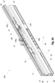
Fig. 1 is an overall perspective view of the telescopic guide in extended position according to an embodiment of the invention; -
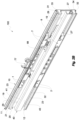
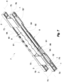
Figs. 2A and2B are overall perspective views of the telescopic guide ofFigure 1 in closed position; -
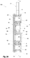
Figs. 3A and3B are a front view and an overall rear view of the telescopic guide ofFigure 2A , respectively; -
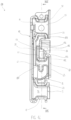
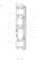
Figs. 4A and4B are a sectional view according to the line IVA-IVA and a sectional view according to the line IVB-IVB of the telescopic guide ofFigure 2A , respectively; -
Fig. 5 is a sectional view along the line V-V of the telescopic guide ofFigure 3A ; -
Figs. 6-12 are perspective views of details of the telescopic guide of the preceding figures; -
Fig. 13 is an overall perspective view of the telescopic guide in extended position according to a further embodiment of the invention; -
Figures 14 and15 are a front view and an overall rear view of the telescopic guide ofFigure 13 , respectively; -
Fig. 16 is a sectional view along the line XVI-XVI of the guide ofFig. 14 ; -
Fig. 17 is a perspective view of a detail of the guide ofFig. 13 in a partially closed position. - In the figures, 100 generally indicates a telescopic guide for a drawer of a piece of furniture.
- The
telescopic guide 100 comprises abase support 10 and afloating support 20, shown inFigure 1 in the extended position and inFigure 2A in the closed position. Thebase support 10 can be fixed to the side of the piece of furniture and comprises a pair of upper andlower base rails - Advantageously, the
floating support 20 is interposed between theupper base rail 11 and thelower base rail 12 so as to reduce the lateral overall dimension of saidtelescopic guide 100, i.e. the overall dimension occupied by saidtelescopic guide 100 in a horizontal direction transversal to a sliding direction X of saidtelescopic guide 100. - Similarly, the
floating support 20 comprises a pair of upper and lower floatingrails - The
telescopic guide 100 also comprises a plurality of grooved rollers which are interposed between said pair ofbase rails rails 21, 22.As will be illustrated in greater detail below, the presence of at least three grooved rollers is required to allow a linear sliding of thefloating support 20 with respect to thebase support 10. However, it may be preferable to use a higher number of grooved rollers to increase load distribution. - As mentioned above, the grooved rollers comprise at least one upper grooved
roller 1 which is interposed between theupper base rail 11 and the upper floatingrail 21 and at least one lowergrooved roller 2 which is interposed between the lower floatingrail 22 and thelower base rail 12, the uppergrooved roller 1 and the lowergrooved roller 2 being preferably substantially equal to each other. - Furthermore, on the basis of what has been illustrated above, at least one additional grooved roller is provided to be selected from an additional upper
planar roller 1 which is interposed between theupper base rail 11 and the upper floatingrail 21 or an additional lowerplanar roller 2 which is interposed between the lower floatingrail 22 and thelower base rail 12. - An embodiment of the
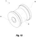
grooved rollers Fig. 10 .Thegrooved rollers telescopic guide 100 so that a rolling of thegrooved rollers floating support 20 and thebase support 10 in parallel with said sliding direction X. Advantageously, the presence of at least threegrooved rollers base rails floating rails floating support 20 with respect to thebase support 10 about an axis parallel to the horizontal rolling axes H. - Each of the
base rails floating rails sliding surface 23, preferably convex, which extends in parallel with said sliding direction X. In other words, thesliding surface 23 is formed by a convexity in relief with respect to a lateral portion of the respective rail. - Each of the
grooved rollers peripheral groove 3 which is configured to match to a respectiveconvex sliding surface 23 so as to limit lateral play, i.e. in a direction parallel to the rolling axis, between theperipheral groove 3 and said respective slidingsurface 23. - According to a further advantageous aspect, the coupling between the
grooved rollers sliding surfaces 23 prevents, or in any case significantly limits, a derailing (also called "slip off") of thefloating support 20 from its operating position in thefixed support 10 in the event of a lateral impact against thetelescopic guide 100 or against the drawer supported by it. - Preferably, the
grooved rolls peripheral groove 3 can be axially symmetrical with respect to the horizontal rolling axes H of thegrooved rollers - Preferably, as shown in
Fig. 4A theperipheral groove 3 defines a substantially H-shaped contour at anysection 30 of thegrooved rollers grooved rollers - In one aspect, the
base support 10 can be fixed to the lateral wall of a piece of furniture by means of fixing means such as screws or rivets. The fixing means can pass through a pair of fixingholes 19 provided in alateral wall 18 of the base support 10.In the condition in which thetelescopic guide 100 is closed, the fixing holes 19 can be advantageously accessible through a pair of throughholes 29 provided in alateral wall 28 of the floatingsupport 20. - According to a further advantageous aspect, the
telescopic guide 100 comprises abracket 40 which can be fixed to the drawer which extends telescopically from thebase 10 and floating supports 20.Thebracket 40 in turn comprises a pair of upper and lower abutment surfaces 41, 42, respectively, which are mutually opposing and extending in parallel with the sliding direction X. - Advantageously, the pair of abutment surfaces 41, 42 is interposed between the upper floating
rail 21 and the lower floatingrail 22 so as to reduce the lateral overall dimension of thetelescopic guide 100. - In some preferred embodiments, the
bracket 40 has an L-shaped cross section visible inFig. 3A .Said L-shaped cross section comprises the abutment surfaces 41, 42 on a -in use- horizontal plane, and also avertical surface 43 which is configured to be fixed to a lateral wall of a drawer. - Advantageously,
planar rollers support 20 and saidbracket 40. - Similarly to what is illustrated with reference to the grooved rollers, the
planar rollers planar roller 51 which is interposed between the upper floatingrail 21 and theupper abutment surface 41 and at least one lowerplanar roller 52 which is interposed between thelower abutment surface 42 and the lower floatingrail 22, the upperplanar roller 51 and the lowerplanar roller 52 preferably being substantially equal to each other. - In addition, at least one additional planar roller is provided to be selected from an additional upper
planar roller 51 which is interposed between the upper floatingrail 21 and theupper abutment surface 41 or an additional lowerplanar roller 52 which is interposed between thelower abutment surface 42 and the lower floatingrail 22. An embodiment of theplanar rollers Fig. 11 .Theplanar rollers planar rollers bracket 40 and the floatingsupport 20 in parallel with said sliding direction X. - According to a further advantageous aspect, each of the floating rails 21, 22 comprises a sliding
surface 24 which is opposite a respective slidingsurface 23, and each of theplanar rollers surface 54 which is configured to engage in a respective slidingsurface 24, as shown inFig. 3A .Advantageously, the slidingsurface 24 of the floating rails 21, 22 has a shape which is complementary with respect to thesurface 23, said sliding surfaces preferably being the former concave and the latter convex. Similarly, the rollingsurface 54 of theplanar rollers surface 24 of the floating rails 21, 22. Also in this case it is therefore possible to have convex and concave surfaces, respectively. This expedient prevents lateral play between theconvex rolling surface 54 and the respective concave slidingsurface 24. It will also be appreciated that also in this case the term concave surface and convex surface is intended to indicate a surface which forms a concavity or a convexity, respectively, with respect to a corresponding adjacent portion. - Preferably, at least one
lateral roller 6 is interposed between the floatingsupport 20 and thebracket 40. An embodiment of thelateral roller 6 is shown inFig. 12 . - The
lateral roller 6 has a vertical rolling axis V so that a rolling of thelateral roller 6 about the vertical rolling axis V allows relative sliding between the floatingsupport 20 and thebracket 40 in parallel with the sliding direction X. Advantageously, the at least onelateral roller 6 facilitates the sliding of thebracket 40 along the floatingsupport 20 in the presence of a horizontal load transversal to said sliding direction X. In one aspect, afirst runner 7 is provided which is interposed between thebase support 10 and the floatingsupport 20 so as to secure the floatingsupport 20 for translational movement with respect to thebase support 10 in the sliding direction X. - The
first runner 7 is secured for translational movement with respect to thebase support 10 in said sliding direction X. Thefirst runner 7 comprises anupper cage 71 which is configured to define a position of the uppergrooved rollers 1 and alower cage 72 which is configured to define a position of the lowergrooved rollers 2. Preferably, thefirst runner 7 further comprises astructural connection 73 between theupper cage 71 and thelower cage 72. - In one embodiment, as shown in
Figures 6 and7 , theupper cage 71 and thelower cage 72 comprisefirst sides 75 which are configured to prevent a horizontal displacement of saidgrooved rollers first runner 7 in a direction transversal to the sliding direction X. - Advantageously, the
first sides 75 are structurally connected throughfirst partitions 76 which are configured to prevent a horizontal displacement of thegrooved rollers first runner 7 in a direction parallel to the sliding direction X. Preferably, as shown inFig. 4A , thefirst sides 75 at their internal surfaces 75' turned towards thegrooved rollers axial cavities 4 of thegrooved rollers grooved rollers first bulges 74 and theaxial cavities 4 are axially symmetrical. Preferably, the diameter of theaxial cavities 4 is greater than the diameter of thefirst bulges 74 so as to allow radial play of thegrooved rollers - In one aspect, the
first bulges 74 allow to achieve a snap coupling, i.e. of the "snap-fit" type, between thefirst runner 7 and thegrooved rollers grooved rollers first runner 7 and of thegrooved rollers base support 10 comprises anupper edge 13 and alower edge 14 which extend along theupper base rail 11 and along thelower base rail 12, respectively. Theupper edge 13 and thelower edge 14 are configured to limit tilting of theupper cage 71 and thelower cage 72, respectively, transversely to said sliding direction X so as to prevent a derailing of saidfirst runner 7 from said pair of base rails 11, 12. This expedient advantageously prevents a release of the floatingsupport 20 from thefirst runner 7 transversely to said sliding direction X. - According to a further advantageous aspect, a
second runner 8 is provided which is interposed between the floatingsupport 20 and thebracket 40. Thesecond runner 8 is configured to define the position of theplanar rollers - In one embodiment, as shown in
Figures 8 and9 , thesecond runner 8 comprisessecond sides 85 which are configured to prevent a horizontal displacement of theplanar rollers second runner 8 in a direction transversal to the sliding direction X. - Advantageously, the
second sides 85 are structurally connected throughsecond partitions 86 which are configured to prevent a horizontal displacement of theplanar rollers second runner 8 in a direction parallel to the sliding direction X. - Preferably, the
second sides 85 at their internal surfaces 85' turned towards theplanar rollers axial cavities 53 of theplanar rollers planar rollers second runner 8. In advantageous embodiments, the second bulges 84 and theaxial cavities 53 are axially symmetrical. Preferably, the diameter of theaxial cavities 53 is greater than the diameter of the second bulges 84 so as to allow radial play of theplanar rollers - According to a further advantageous aspect, the
second runner 8 compriseshorizontal walls 89 which are configured to prevent a vertical displacement of the at least onelateral roller 6 with respect to saidsecond runner 8. - Advantageously, the horizontal walls are structurally connected through
lateral partitions 87 which are configured to prevent a horizontal displacement of the at least onelateral roller 6 with respect to thesecond runner 8 in a direction parallel to the sliding direction X. - Preferably, the
horizontal walls 89 at their internal surfaces 89' turned towards thelateral roller 6 comprise second bulges 84 which are configured to engage in respectiveaxial cavities 64 of thelateral roller 6 so as to prevent a horizontal displacement of thelateral roller 6 with respect to thesecond runner 8 transversely to the sliding direction X. - Preferably, the diameter of the
axial cavities 64 is greater than the diameter of the second bulges 84 so as to allow radial play of thelateral roller 6. - In one aspect, the second bulges 84 allow to achieve a snap coupling, i.e. of the "snap-fit" type, between the
second runner 8 and theplanar rollers planar rollers lateral roller 6 and reduces the number of components so as to achieve a simple and economical coupling. Furthermore, the snap coupling reduces the assembly, disassembly and maintenance times of thesecond runner 8, of theplanar rollers lateral roller 6. Preferably, as shown inFig. 3A , thesecond runner 8 comprises atongue 81 which is configured to engage in a concave slidingsurface 24 of the pair of floatingrails 21, 22.Thetongue 81 allows to secure thesecond runner 8 for translational movement with respect to the floatingsupport 20 in the sliding direction X of the telescopic guide 100.Advantageously, thetongue 81 is resiliently deformable in order to allow inserting thesecond runner 8 in the floatingsupport 20 transversely to the sliding direction X, i.e. inserting thesecond runner 8 laterally in the floatingsupport 20 without having to fit thesecond runner 8 into the floatingsupport 20 in the sliding direction X. If necessary, thetongue 81 is resiliently deformable in order to allow the lateral release of thesecond runner 8 from the floatingsupport 20, i.e. the release of thesecond runner 8 from the floatingsupport 20 transversely to the sliding direction X. - According to a further advantageous aspect, the floating
support 20 comprises an internal rear wing 25 and an internalfront wing 26 which are configured to delimit the path of thesecond runner 8 with respect to the floatingsupport 20 in said sliding direction X under the condition in which thetelescopic guide 100 is extended and under the condition in which thetelescopic guide 100 is closed, respectively. - In one aspect, as shown in
Fig. 5 , afirst stop 77 is provided which is fixedly joined to thebase support 10 and is configured to delimit the path of thefirst runner 7 with respect to thebase support 10 in the sliding direction X. Thefirst stop 77 is removable to allow thefirst runner 7 to be removed from thebase support 10 in parallel with the sliding direction X. - Preferably, the
first stop 77 is intended to collide alternatively with a first front end stop surface 78' or with a first rearend stop surface 78" of thefirst runner 7 so as to stop the travel of thefirst runner 7 with respect to thebase support 10 in the sliding direction X at a predetermined point. Preferably, thefirst stop 77 comprises afirst block 78 intended to collide with the first frontend stop surface 78'.Preferably, afirst stop hole 15 is provided through one of the base rails 11, 12 which is configured to receive the first block 78.According to a further advantageous aspect, thefirst stop 77 comprises ahook 79 intended to collide with the first rearend stop surface 78".Thehook 79 is configured to engage in a first hooking hole 15' provided in said base rail, thehook 79 being configured to fix in a removable way thefirst stop 77 to saidbase support 10. - According to a further advantageous aspect, as shown in
Fig. 5 , the floatingsupport 20 comprises a pair ofexternal wings 27 which are configured to engage on respective abutment surfaces 27' of saidfirst runner 7 so as to stop the advancement of said floatingsupport 20 with respect to thefirst runner 7 at a predetermined point. Preferably, theexternal wings 27 are located at one end of the floatingsupport 20 in the sliding direction X. - In one aspect, the
upper base rail 11 and thelower base rail 12 comprise an upperlongitudinal groove 31 and a lowerlongitudinal groove 32, respectively, which extend in parallel with the sliding direction X. Furthermore, as shown inFig. 3B , the floatingsupport 20 comprises anupper tooth 33 and alower tooth 34 which are configured to engage in a sliding manner in the upperlongitudinal groove 31 and in the lowerlongitudinal groove 32, respectively, so as to prevent a derailing of the floatingsupport 20 with respect to the pair of base rails 11, 12.Preferably, theupper tooth 33 and thelower tooth 34 extend from the upper 21 and lower 22 floating rail, respectively, in the vertical direction away from the respective rail, until they engage in the respective groove. Preferably, theupper tooth 33 and thelower tooth 34 are located at one end of the floatingsupport 20 in the sliding direction X. According to a further advantageous aspect, theupper tooth 33 and thelower tooth 34 are molded in rigid plastic material and are configured to be keyed onto the pair ofexternal wings 27. - In some embodiments, as shown in
Fig. 5 , asecond stop 88 is provided which is fixedly joined to thebracket 40 and configured to delimit the path of saidbracket 40 with respect to saidsecond runner 8 in said sliding direction X. - Preferably, the
second stop 88 is molded in rigid plastic material and is keyed to a keyingwing 17 provided in thebracket 40. - Preferably, the
second stop 88 is intended to collide alternatively with a second front end stop surface 82' or with a second rearend stop surface 82" of thesecond runner 8 so as to stop the travel of thebracket 40 with respect to thesecond runner 8 in the sliding direction X at a predetermined point. - According to a further advantageous aspect, as shown in
Fig. 4B , thesecond runner 8 comprises alongitudinal edge 97 which extends in parallel with said sliding direction X, saidlongitudinal edge 97 being configured to secure thesecond stop 88 for sliding in the sliding direction X so as to prevent a release of thebracket 40 from thesecond runner 8 transversely to the sliding direction X. Advantageously, this expedient ensures that thebracket 40 remains connected in a sliding manner to thesecond runner 8 even in the event of a lateral impact against thetelescopic guide 100. - Preferably, the
second stop 88 is removable so as to allow thebracket 40 to be removed from thesecond runner 8 in the sliding direction X. - In one aspect, the
first runner 7 and thesecond runner 8 slide inside thebase support 10 and inside the floatingsupport 20, respectively, so as to reduce the lateral overall dimension of thetelescopic guide 100. - In one aspect, the
first runner 7 and/or thesecond runner 8 comprise a joint 9 which is interposed between the seats of twogrooved rollers planar rollers grooved rollers planar rollers - According to a further advantageous aspect, the joint 9 is of the telescopic type, i.e. it comprises a
rod 92 which slides along atrack 91 in a direction parallel to the sliding direction X so as to vary the length of the joint 9 in the sliding direction X. Preferably, thetrack 91 and therod 92 comprise aninternal surface 93 and anexternal surface 94, respectively, in contact with each other. Theinternal surface 93 and theexternal surface 94 are specularly corrugated in order to engage one on the other so as to prevent a translation of therod 92 with respect to thetrack 91 unless a force is applied in the sliding direction X, said force having a value equal to or greater than a minimum pre-established threshold for adjusting the length of thejoint 9. Preferably, thetrack 91 comprises areading surface 95 on which a graduatedscale 96 is reproduced, which is configured to allow the reading of a position of saidrod 92 along thetrack 91. - The
internal surface 93 and theexternal surface 94 which is specularly corrugated as well as the graduatedscale 96 allow adjusting the length of saidfirst runner 7 and/or saidsecond runner 8 quickly and without the aid of further tools, thus facilitating the assembly and the maintenance of thetelescopic slide 100. - In preferred embodiments, the
base support 10, the floatingsupport 20 and thebracket 40 are obtained by mechanical processing of a metal sheet such as for example a stainless steel sheet. Preferably, the base rails 11, 12, the floating rails 21, 22 and the abutment surfaces 41, 42 are produced by blanking and bending said metal sheet. According to a further advantageous aspect, thefirst runner 7 and thesecond runner 8 are produced by molding plastic materials. In this way, the manufacturing process of thetelescopic guide 100 is advantageously quick and economical. - Advantageously, the
grooved rollers planar rollers lateral roller 6 are made of a material such as Teflon which is configured to minimize the friction coefficient among therollers base support 10, of the floatingsupport 20 and of thebracket 40. - A more preferred example of embodiment of the invention is described below with reference to
Figures 13 to 17 . - In this example, the
first stop 77 which delimits the path of thefirst runner 7 with respect to thebase support 10 in the sliding direction X, is fixedly joined to the front longitudinal end 98 of thebase support 10, preferably at the upper base rail 11.In this way, thefirst stop 77 prevents thefirst runner 7 from coming off thebase support 10 during the extension phase of thetelescopic guide 100 and the opening phase of the relative drawer. - It should be noted that, in this context, the terms "front" and "rear" refer to the opposing sides of the
telescopic guide 100 turned towards the opening and closing direction, respectively, of the guide itself and of the relative drawer. - As highlighted in
Fig. 17 , thebracket 40 preferably comprises: the abutment surfaces 41, 42 on a - in use - horizontal plane; thevertical surface 43 which is configured to be fixed to a lateral wall of a drawer; and also a second vertical surface 44 which in use is parallel and adjacent to thelateral wall 28 of the floatingsupport 20. - In one aspect shown in
Fig. 13 , the second vertical surface 44 develops along a portion of the longitudinal length of thebracket 40 comprised between the front longitudinal end 99 of thebracket 40 and the fixing point of thesecond stop 88. Advantageously, an anti-slip device 101 is provided, which is fixedly joined to the floatingsupport 20 and is configured to prevent thebracket 40 from slipping off, as shown inFig. 17 . - In one aspect, the anti-slip device 101 is removably fixed to the front longitudinal end 90 of the floating
support 20, preferably by means of a shape coupling. - A saddle 105 which is configured to support the
lower abutment surface 42 of thebracket 40 sliding in the sliding direction X is defined in the anti-slip device 101. - Advantageously, a
projection 102 develops from the saddle 105 whichprojection 102 is configured to engage in a sliding manner in a longitudinal slot 103 defined in thebracket 40 in the sliding direction X. In use, theprojection 102 is oriented vertically so as to secure thebracket 40 for translational movement in the direction X without allowing lateral deviations of the bracket. - According to a further advantageous aspect, the anti-slip device 101 has a
shoulder 104 facing the saddle 105 and configured to abut the upper profile 106 of the second vertical surface 44 of thebracket 40 during the sliding thereof in the sliding direction X. - In order to ensure a better anchoring of the anti-slip device 101 to the floating
support 20, the anti-slip device 101 can include a protrusion 103 which fits into the upper floatingrail 21. - The invention thus solves the proposed problem achieving numerous advantages including:
- the elimination of the risk of slipping off, i.e. of the risk of a derailing of the guide transversally to the sliding direction following a lateral impact,
- the reduction of the lateral overall dimension of the telescopic guide,
- the reduction of the manufacturing costs of said guide,
- the simplification of the guide assembly process,
- a better sliding of the guide,
- the possibility of at least partially disassembling the guide without having to remove it.
Claims (15)
- A telescopic guide (100) for a drawer of a piece of furniture comprising:• a base support (10) which can be fixed to the side of said piece of furniture, said base support (10) comprising a pair of base rails (11, 12) which include an upper base rail (11) and a lower base rail (12),• a floating support (20) comprising a pair of floating rails (21, 22) which include an upper floating rail (21) and a lower floating rail (22),• at least three grooved rollers (1, 2) which are interposed between said pair of base rails (11, 12) and said pair of floating rails (21, 22), said grooved rollers (1, 2) having respective horizontal rolling axes (H) which are perpendicular to a sliding direction (X) of said telescopic guide (100), each of said base rails (11, 12) and of said floating rails (21, 22) comprising a sliding surface (23) which extends in parallel with said sliding direction (X), each of said grooved rollers (1, 2) comprising a peripheral groove (3) which is configured to match to a respective sliding surface (23) and in contact therewith so as to limit lateral play between said peripheral groove (3) and said respective sliding surface (23).
- A telescopic guide (100) according to claim 1, wherein said peripheral groove (3) defines a substantially H-shaped contour (31) at any section (30) of said grooved rollers (1, 2) which are intersected by any plane which passes through the horizontal rolling axis (H) of said grooved rollers (1, 2).
- A telescopic guide (100) according to claim 1 or claim 2, comprising:• a bracket (40) which can be fixed to said drawer, said bracket (40) comprising a pair of abutment surfaces (41, 42) which are mutually opposing, said pair of abutment surfaces (41, 42) comprising an upper abutment surface (41) and a lower abutment surface (42), said abutment surfaces (41, 42) extending in parallel with said sliding direction (X),• at least three planar rollers (51, 52), said planar rollers (51, 52) comprising at least one upper planar roller (51) which is interposed between said upper floating rail (21) and said upper abutment surface (41) and at least one lower planar roller (52) which is interposed between said lower abutment surface (42) and said lower floating rail (22) and at least one additional planar roller to be selected from an additional upper planar roller (51) or an additional lower planar roller (52), said planar rollers (51, 52) having respective horizontal rolling axes (H) which are perpendicular to said sliding direction (X) so that a rolling of said planar rollers (51, 52) about said respective horizontal rolling axes (H') allows relative sliding between said bracket (40) and said floating support (20) in parallel with said sliding direction (X).
- A telescopic guide (100) according to the preceding claim, wherein each of said floating rails (21, 22) comprises an additional sliding surface (24) which is opposite a respective sliding surface (23), each of said planar rollers (51, 52) comprising a rolling surface (54) which is configured to engage in a respective additional sliding surface (24) so as to prevent lateral play between said rolling surface (54) and said additional respective sliding surface (24), said additional sliding surface (24) being preferably concave.
- A telescopic guide (100) according to claim 4, wherein said rolling surface (54) has a shape which is complementary with respect to said additional sliding surface (24), said rolling surface (54) being preferably convex.
- A telescopic guide (100) according to any one of claims 3 to 5, comprising at least one lateral roller (6) which is interposed between said floating support (20) and said bracket (40), said lateral roller (6) preferably having a vertical rolling axis (V) so that a rolling of said lateral roller (6) about said vertical rolling axis (V) allows relative sliding between said floating support (20) and said bracket (40) in parallel with said sliding direction (X).
- A telescopic guide (100) according to any one of the preceding claims, comprising a first runner (7) which is secured for translational movement with respect to said base support (10) in said sliding direction (X), said first runner (7) comprising:• an upper cage (71) which is configured to define a seat of the at least one upper grooved roller (1),• a lower cage (72) which is configured to define a seat of the at least one lower grooved roller (2),• a structural connection (73) between said upper cage (71) and said lower cage (72),said first runner (7) securing said floating support (20) for translational movement with respect to said base support (10) in said sliding direction (X).
- A telescopic guide (100) according to claim 7, wherein said base support (10) comprises an upper edge (13) and a lower edge (14) which extend along said upper base rail (11) and along said lower base rail (12), respectively, said upper edge (13) and said lower edge (14) being configured to limit tilting (T) of said upper cage (71) and of said lower cage (72), respectively, transversely to said sliding direction (X) so as to prevent a release of said floating support (20) from said first runner (7) transversely to said sliding direction (X).
- A telescopic guide (100) according to any one of claims 3 to 8, comprising a second runner (8) which is configured to define seats of said planar rollers (51, 52), said second runner (8) comprising a tongue (81) which is configured to engage in said concave sliding surface (24) so as to secure said second runner (8) for translational movement with respect to said floating support (20) in said sliding direction (X), said tongue (81) being resiliently deformable in order to allow a release of said second runner (8) from said floating support (20) transversely to said sliding direction (X).
- A telescopic guide (100) according to any one of claims 3 to 9, comprising at least one device to be selected from a first stop (77) which is fixedly joined to said base support (10) and a second stop (88) which is fixedly joined to said bracket (40), said first stop (77) delimiting a path of said first runner (7) with respect to said base support (10) in said sliding direction (X), said first stop (77) being removable in order to allow said first runner (7) to be removed from said base support (10) in parallel with said sliding direction (X), said second stop (88) delimiting a path of said bracket (40) with respect to said second runner (8) in said sliding direction (X).
- A telescopic guide (100) according to the preceding claim, wherein said second runner (8) comprises a longitudinal edge (97) which extends in parallel with said sliding direction (X), said longitudinal edge (97) being configured to secure said second stop (88) for sliding in said sliding direction (X) so as to prevent a release of said bracket (40) from said second runner (8) transversely to said sliding direction (X).
- A telescopic guide (100) according to any one of the preceding claims, when dependent on claim 3 and either claims 7 or claim 9, wherein said first runner (7) or said second runner (8) comprises a joint (9) which is interposed between the seats of two grooved rollers (1, 2) or of two planar rollers (51, 52), respectively, said joint (9) having a length in said sliding direction (X) which is adjustable so as to adjust a horizontal distance (D) between said two grooved rollers (1, 2) or between said two planar rollers (51, 52), respectively.
- A telescopic guide (100) according to any one of the preceding claims, wherein said grooved rollers (1, 2) comprise at least one upper grooved roller (1) which is interposed between said upper base rail (11) and said upper floating rail (21) and at least one lower grooved roller (2) which is interposed between said lower floating rail (22) and said lower base rail (12) and at least one additional grooved roller to be selected from an additional upper grooved roller (1) or an additional lower grooved roller (2).
- A telescopic guide (100) according to any one of the preceding claims, wherein said upper base rail (11) and said lower base rail (12) comprise an upper longitudinal groove (31) and a lower longitudinal groove (32), respectively, which extend in parallel with said sliding direction (X) and in which said floating support (20) comprises an upper tooth (33) and a lower tooth (34) which are configured to engage in a sliding manner in said upper longitudinal groove (31) and in said lower longitudinal groove (32), respectively, so as to prevent a derailing of said floating support (20) with respect to said pair of base rails (11, 12).
- A telescopic guide (100) according to any one of the preceding claims, wherein said sliding surface (23) has a convex shape and preferably defines a relief with respect to respective lateral portions of said base rails (11, 12) and of said floating rails (21 ,22).
Applications Claiming Priority (2)
| Application Number | Priority Date | Filing Date | Title |
|---|---|---|---|
| IT102019000019184A IT201900019184A1 (en) | 2019-10-17 | 2019-10-17 | Telescopic runner for drawer |
| PCT/IB2020/059772 WO2021074885A1 (en) | 2019-10-17 | 2020-10-16 | Telescopic guide for drawer |
Publications (2)
| Publication Number | Publication Date |
|---|---|
| EP4044869A1 EP4044869A1 (en) | 2022-08-24 |
| EP4044869B1 true EP4044869B1 (en) | 2023-11-01 |
Family
ID=70918783
Family Applications (1)
| Application Number | Title | Priority Date | Filing Date |
|---|---|---|---|
| EP20807496.3A Active EP4044869B1 (en) | 2019-10-17 | 2020-10-16 | Telescopic guide for drawer |
Country Status (4)
| Country | Link |
|---|---|
| EP (1) | EP4044869B1 (en) |
| ES (1) | ES2971701T3 (en) |
| IT (1) | IT201900019184A1 (en) |
| WO (1) | WO2021074885A1 (en) |
Families Citing this family (1)
| Publication number | Priority date | Publication date | Assignee | Title |
|---|---|---|---|---|
| CN115199130B (en) * | 2022-07-21 | 2024-10-18 | 赵铁创 | Road bridge construction pavement protection structure |
Family Cites Families (2)
| Publication number | Priority date | Publication date | Assignee | Title |
|---|---|---|---|---|
| AT361171B (en) * | 1975-07-22 | 1981-02-25 | Blum Gmbh Julius | DOUBLE DRAWER |
| DE2536743A1 (en) * | 1975-08-18 | 1977-02-24 | Kumepa Patent Gmbh Ets | Drawer runners consisting of flanges moving between fixed rollers - have one flange of pair profiled to prevent drawer from moving sideways |
-
2019
- 2019-10-17 IT IT102019000019184A patent/IT201900019184A1/en unknown
-
2020
- 2020-10-16 ES ES20807496T patent/ES2971701T3/en active Active
- 2020-10-16 EP EP20807496.3A patent/EP4044869B1/en active Active
- 2020-10-16 WO PCT/IB2020/059772 patent/WO2021074885A1/en not_active Ceased
Also Published As
| Publication number | Publication date |
|---|---|
| WO2021074885A1 (en) | 2021-04-22 |
| EP4044869A1 (en) | 2022-08-24 |
| ES2971701T3 (en) | 2024-06-06 |
| IT201900019184A1 (en) | 2021-04-17 |
Similar Documents
| Publication | Publication Date | Title |
|---|---|---|
| US8430567B2 (en) | Load adaptive roller carriage assembly | |
| CN111556720B (en) | Drawer pull-out guide | |
| US20170258226A1 (en) | Cabinet slide system | |
| CN103512307B (en) | Sliding installation structure and refrigeration equipment including the sliding installation structure | |
| US20120319548A1 (en) | Pull-out guide for a drawer | |
| US20160281406A1 (en) | Sliding door top guide fitting | |
| USRE34108E (en) | Pull-out guide for drawers | |
| JP7428804B2 (en) | Guide assembly for guiding at least one sliding door or folding sliding door | |
| CN113039338B (en) | Arrangement for guiding sliding doors | |
| US20080271474A1 (en) | Domestic Refrigerator Provided with Shelves | |
| US11452374B2 (en) | Sliding element guide system | |
| CN113227526B (en) | Sliding door fitting and furniture item | |
| CN109922693B (en) | Drawer pull-out guide | |
| CA3111026A1 (en) | Reinforced shelves, kits therefor and shelving units comprising reinforced shelves | |
| WO2021074885A1 (en) | Telescopic guide for drawer | |
| EP1689264B1 (en) | Drawer pull out guide rail | |
| RU2685812C2 (en) | Guide device for sliding door direction and body furniture article | |
| US7396092B2 (en) | Sliding guide for drawers and other furniture parts slide out of the body of a piece of furniture | |
| CA1038919A (en) | Drawer track for heavy drawers | |
| CN114401650B (en) | Pull out the guide | |
| JP2000501303A (en) | Bottom-mounted drawer guide device for drawers | |
| KR20120006945U (en) | Shelf device for bathroom | |
| CN115003194B (en) | Pull out the guide | |
| CN109072975B (en) | Sliding support accessory using retaining strip | |
| CN113329667B (en) | drawer |
Legal Events
| Date | Code | Title | Description |
|---|---|---|---|
| STAA | Information on the status of an ep patent application or granted ep patent |
Free format text: STATUS: UNKNOWN |
|
| STAA | Information on the status of an ep patent application or granted ep patent |
Free format text: STATUS: THE INTERNATIONAL PUBLICATION HAS BEEN MADE |
|
| PUAI | Public reference made under article 153(3) epc to a published international application that has entered the european phase |
Free format text: ORIGINAL CODE: 0009012 |
|
| STAA | Information on the status of an ep patent application or granted ep patent |
Free format text: STATUS: REQUEST FOR EXAMINATION WAS MADE |
|
| 17P | Request for examination filed |
Effective date: 20220429 |
|
| AK | Designated contracting states |
Kind code of ref document: A1 Designated state(s): AL AT BE BG CH CY CZ DE DK EE ES FI FR GB GR HR HU IE IS IT LI LT LU LV MC MK MT NL NO PL PT RO RS SE SI SK SM TR |
|
| DAV | Request for validation of the european patent (deleted) | ||
| DAX | Request for extension of the european patent (deleted) | ||
| GRAP | Despatch of communication of intention to grant a patent |
Free format text: ORIGINAL CODE: EPIDOSNIGR1 |
|
| STAA | Information on the status of an ep patent application or granted ep patent |
Free format text: STATUS: GRANT OF PATENT IS INTENDED |
|
| INTG | Intention to grant announced |
Effective date: 20230612 |
|
| GRAS | Grant fee paid |
Free format text: ORIGINAL CODE: EPIDOSNIGR3 |
|
| GRAA | (expected) grant |
Free format text: ORIGINAL CODE: 0009210 |
|
| STAA | Information on the status of an ep patent application or granted ep patent |
Free format text: STATUS: THE PATENT HAS BEEN GRANTED |
|
| AK | Designated contracting states |
Kind code of ref document: B1 Designated state(s): AL AT BE BG CH CY CZ DE DK EE ES FI FR GB GR HR HU IE IS IT LI LT LU LV MC MK MT NL NO PL PT RO RS SE SI SK SM TR |
|
| REG | Reference to a national code |
Ref country code: GB Ref legal event code: FG4D |
|
| REG | Reference to a national code |
Ref country code: CH Ref legal event code: EP |
|
| REG | Reference to a national code |
Ref country code: IE Ref legal event code: FG4D |
|
| REG | Reference to a national code |
Ref country code: DE Ref legal event code: R096 Ref document number: 602020020416 Country of ref document: DE |
|
| REG | Reference to a national code |
Ref country code: LT Ref legal event code: MG9D |
|
| REG | Reference to a national code |
Ref country code: NL Ref legal event code: MP Effective date: 20231101 |
|
| PG25 | Lapsed in a contracting state [announced via postgrant information from national office to epo] |
Ref country code: GR Free format text: LAPSE BECAUSE OF FAILURE TO SUBMIT A TRANSLATION OF THE DESCRIPTION OR TO PAY THE FEE WITHIN THE PRESCRIBED TIME-LIMIT Effective date: 20240202 |
|
| PG25 | Lapsed in a contracting state [announced via postgrant information from national office to epo] |
Ref country code: IS Free format text: LAPSE BECAUSE OF FAILURE TO SUBMIT A TRANSLATION OF THE DESCRIPTION OR TO PAY THE FEE WITHIN THE PRESCRIBED TIME-LIMIT Effective date: 20240301 |
|
| PG25 | Lapsed in a contracting state [announced via postgrant information from national office to epo] |
Ref country code: LT Free format text: LAPSE BECAUSE OF FAILURE TO SUBMIT A TRANSLATION OF THE DESCRIPTION OR TO PAY THE FEE WITHIN THE PRESCRIBED TIME-LIMIT Effective date: 20231101 |
|
| PG25 | Lapsed in a contracting state [announced via postgrant information from national office to epo] |
Ref country code: NL Free format text: LAPSE BECAUSE OF FAILURE TO SUBMIT A TRANSLATION OF THE DESCRIPTION OR TO PAY THE FEE WITHIN THE PRESCRIBED TIME-LIMIT Effective date: 20231101 |
|
| PG25 | Lapsed in a contracting state [announced via postgrant information from national office to epo] |
Ref country code: NL Free format text: LAPSE BECAUSE OF FAILURE TO SUBMIT A TRANSLATION OF THE DESCRIPTION OR TO PAY THE FEE WITHIN THE PRESCRIBED TIME-LIMIT Effective date: 20231101 Ref country code: LT Free format text: LAPSE BECAUSE OF FAILURE TO SUBMIT A TRANSLATION OF THE DESCRIPTION OR TO PAY THE FEE WITHIN THE PRESCRIBED TIME-LIMIT Effective date: 20231101 Ref country code: IS Free format text: LAPSE BECAUSE OF FAILURE TO SUBMIT A TRANSLATION OF THE DESCRIPTION OR TO PAY THE FEE WITHIN THE PRESCRIBED TIME-LIMIT Effective date: 20240301 Ref country code: GR Free format text: LAPSE BECAUSE OF FAILURE TO SUBMIT A TRANSLATION OF THE DESCRIPTION OR TO PAY THE FEE WITHIN THE PRESCRIBED TIME-LIMIT Effective date: 20240202 Ref country code: BG Free format text: LAPSE BECAUSE OF FAILURE TO SUBMIT A TRANSLATION OF THE DESCRIPTION OR TO PAY THE FEE WITHIN THE PRESCRIBED TIME-LIMIT Effective date: 20240201 Ref country code: PT Free format text: LAPSE BECAUSE OF FAILURE TO SUBMIT A TRANSLATION OF THE DESCRIPTION OR TO PAY THE FEE WITHIN THE PRESCRIBED TIME-LIMIT Effective date: 20240301 |
|
| PG25 | Lapsed in a contracting state [announced via postgrant information from national office to epo] |
Ref country code: SE Free format text: LAPSE BECAUSE OF FAILURE TO SUBMIT A TRANSLATION OF THE DESCRIPTION OR TO PAY THE FEE WITHIN THE PRESCRIBED TIME-LIMIT Effective date: 20231101 Ref country code: RS Free format text: LAPSE BECAUSE OF FAILURE TO SUBMIT A TRANSLATION OF THE DESCRIPTION OR TO PAY THE FEE WITHIN THE PRESCRIBED TIME-LIMIT Effective date: 20231101 Ref country code: PL Free format text: LAPSE BECAUSE OF FAILURE TO SUBMIT A TRANSLATION OF THE DESCRIPTION OR TO PAY THE FEE WITHIN THE PRESCRIBED TIME-LIMIT Effective date: 20231101 Ref country code: NO Free format text: LAPSE BECAUSE OF FAILURE TO SUBMIT A TRANSLATION OF THE DESCRIPTION OR TO PAY THE FEE WITHIN THE PRESCRIBED TIME-LIMIT Effective date: 20240201 Ref country code: LV Free format text: LAPSE BECAUSE OF FAILURE TO SUBMIT A TRANSLATION OF THE DESCRIPTION OR TO PAY THE FEE WITHIN THE PRESCRIBED TIME-LIMIT Effective date: 20231101 Ref country code: HR Free format text: LAPSE BECAUSE OF FAILURE TO SUBMIT A TRANSLATION OF THE DESCRIPTION OR TO PAY THE FEE WITHIN THE PRESCRIBED TIME-LIMIT Effective date: 20231101 |
|
| REG | Reference to a national code |
Ref country code: ES Ref legal event code: FG2A Ref document number: 2971701 Country of ref document: ES Kind code of ref document: T3 Effective date: 20240606 |
|
| PG25 | Lapsed in a contracting state [announced via postgrant information from national office to epo] |
Ref country code: DK Free format text: LAPSE BECAUSE OF FAILURE TO SUBMIT A TRANSLATION OF THE DESCRIPTION OR TO PAY THE FEE WITHIN THE PRESCRIBED TIME-LIMIT Effective date: 20231101 |
|
| PG25 | Lapsed in a contracting state [announced via postgrant information from national office to epo] |
Ref country code: CZ Free format text: LAPSE BECAUSE OF FAILURE TO SUBMIT A TRANSLATION OF THE DESCRIPTION OR TO PAY THE FEE WITHIN THE PRESCRIBED TIME-LIMIT Effective date: 20231101 |
|
| PG25 | Lapsed in a contracting state [announced via postgrant information from national office to epo] |
Ref country code: SK Free format text: LAPSE BECAUSE OF FAILURE TO SUBMIT A TRANSLATION OF THE DESCRIPTION OR TO PAY THE FEE WITHIN THE PRESCRIBED TIME-LIMIT Effective date: 20231101 |
|
| PG25 | Lapsed in a contracting state [announced via postgrant information from national office to epo] |
Ref country code: SM Free format text: LAPSE BECAUSE OF FAILURE TO SUBMIT A TRANSLATION OF THE DESCRIPTION OR TO PAY THE FEE WITHIN THE PRESCRIBED TIME-LIMIT Effective date: 20231101 Ref country code: SK Free format text: LAPSE BECAUSE OF FAILURE TO SUBMIT A TRANSLATION OF THE DESCRIPTION OR TO PAY THE FEE WITHIN THE PRESCRIBED TIME-LIMIT Effective date: 20231101 Ref country code: IT Free format text: LAPSE BECAUSE OF FAILURE TO SUBMIT A TRANSLATION OF THE DESCRIPTION OR TO PAY THE FEE WITHIN THE PRESCRIBED TIME-LIMIT Effective date: 20231101 Ref country code: EE Free format text: LAPSE BECAUSE OF FAILURE TO SUBMIT A TRANSLATION OF THE DESCRIPTION OR TO PAY THE FEE WITHIN THE PRESCRIBED TIME-LIMIT Effective date: 20231101 Ref country code: DK Free format text: LAPSE BECAUSE OF FAILURE TO SUBMIT A TRANSLATION OF THE DESCRIPTION OR TO PAY THE FEE WITHIN THE PRESCRIBED TIME-LIMIT Effective date: 20231101 Ref country code: CZ Free format text: LAPSE BECAUSE OF FAILURE TO SUBMIT A TRANSLATION OF THE DESCRIPTION OR TO PAY THE FEE WITHIN THE PRESCRIBED TIME-LIMIT Effective date: 20231101 |
|
| REG | Reference to a national code |
Ref country code: DE Ref legal event code: R097 Ref document number: 602020020416 Country of ref document: DE |
|
| PLBE | No opposition filed within time limit |
Free format text: ORIGINAL CODE: 0009261 |
|
| STAA | Information on the status of an ep patent application or granted ep patent |
Free format text: STATUS: NO OPPOSITION FILED WITHIN TIME LIMIT |
|
| 26N | No opposition filed |
Effective date: 20240802 |
|
| PG25 | Lapsed in a contracting state [announced via postgrant information from national office to epo] |
Ref country code: SI Free format text: LAPSE BECAUSE OF FAILURE TO SUBMIT A TRANSLATION OF THE DESCRIPTION OR TO PAY THE FEE WITHIN THE PRESCRIBED TIME-LIMIT Effective date: 20231101 |
|
| PG25 | Lapsed in a contracting state [announced via postgrant information from national office to epo] |
Ref country code: SI Free format text: LAPSE BECAUSE OF FAILURE TO SUBMIT A TRANSLATION OF THE DESCRIPTION OR TO PAY THE FEE WITHIN THE PRESCRIBED TIME-LIMIT Effective date: 20231101 |
|
| REG | Reference to a national code |
Ref country code: CH Ref legal event code: PL |
|
| GBPC | Gb: european patent ceased through non-payment of renewal fee |
Effective date: 20241016 |
|
| PG25 | Lapsed in a contracting state [announced via postgrant information from national office to epo] |
Ref country code: MC Free format text: LAPSE BECAUSE OF FAILURE TO SUBMIT A TRANSLATION OF THE DESCRIPTION OR TO PAY THE FEE WITHIN THE PRESCRIBED TIME-LIMIT Effective date: 20231101 |
|
| PG25 | Lapsed in a contracting state [announced via postgrant information from national office to epo] |
Ref country code: GB Free format text: LAPSE BECAUSE OF NON-PAYMENT OF DUE FEES Effective date: 20241016 |
|
| PG25 | Lapsed in a contracting state [announced via postgrant information from national office to epo] |
Ref country code: LU Free format text: LAPSE BECAUSE OF NON-PAYMENT OF DUE FEES Effective date: 20241016 Ref country code: BE Free format text: LAPSE BECAUSE OF NON-PAYMENT OF DUE FEES Effective date: 20241031 |
|
| PG25 | Lapsed in a contracting state [announced via postgrant information from national office to epo] |
Ref country code: CH Free format text: LAPSE BECAUSE OF NON-PAYMENT OF DUE FEES Effective date: 20241031 |
|
| REG | Reference to a national code |
Ref country code: BE Ref legal event code: MM Effective date: 20241031 |
|
| PG25 | Lapsed in a contracting state [announced via postgrant information from national office to epo] |
Ref country code: FI Free format text: LAPSE BECAUSE OF FAILURE TO SUBMIT A TRANSLATION OF THE DESCRIPTION OR TO PAY THE FEE WITHIN THE PRESCRIBED TIME-LIMIT Effective date: 20231101 |
|
| REG | Reference to a national code |
Ref country code: AT Ref legal event code: UEP Ref document number: 1626196 Country of ref document: AT Kind code of ref document: T Effective date: 20231101 |
|
| PG25 | Lapsed in a contracting state [announced via postgrant information from national office to epo] |
Ref country code: IE Free format text: LAPSE BECAUSE OF NON-PAYMENT OF DUE FEES Effective date: 20241016 |
|
| PG25 | Lapsed in a contracting state [announced via postgrant information from national office to epo] |
Ref country code: RO Free format text: LAPSE BECAUSE OF FAILURE TO SUBMIT A TRANSLATION OF THE DESCRIPTION OR TO PAY THE FEE WITHIN THE PRESCRIBED TIME-LIMIT Effective date: 20231101 |
|
| PGFP | Annual fee paid to national office [announced via postgrant information from national office to epo] |
Ref country code: DE Payment date: 20251021 Year of fee payment: 6 |
|
| PGFP | Annual fee paid to national office [announced via postgrant information from national office to epo] |
Ref country code: AT Payment date: 20251022 Year of fee payment: 6 |
|
| PGFP | Annual fee paid to national office [announced via postgrant information from national office to epo] |
Ref country code: FR Payment date: 20251030 Year of fee payment: 6 |
|
| PG25 | Lapsed in a contracting state [announced via postgrant information from national office to epo] |
Ref country code: CY Free format text: LAPSE BECAUSE OF FAILURE TO SUBMIT A TRANSLATION OF THE DESCRIPTION OR TO PAY THE FEE WITHIN THE PRESCRIBED TIME-LIMIT; INVALID AB INITIO Effective date: 20201016 |
|
| PGFP | Annual fee paid to national office [announced via postgrant information from national office to epo] |
Ref country code: ES Payment date: 20251216 Year of fee payment: 6 |
|
| PG25 | Lapsed in a contracting state [announced via postgrant information from national office to epo] |
Ref country code: HU Free format text: LAPSE BECAUSE OF FAILURE TO SUBMIT A TRANSLATION OF THE DESCRIPTION OR TO PAY THE FEE WITHIN THE PRESCRIBED TIME-LIMIT; INVALID AB INITIO Effective date: 20201016 |