EP4044784A1 - Storage cabinet - Google Patents
Storage cabinet Download PDFInfo
- Publication number
- EP4044784A1 EP4044784A1 EP19948516.0A EP19948516A EP4044784A1 EP 4044784 A1 EP4044784 A1 EP 4044784A1 EP 19948516 A EP19948516 A EP 19948516A EP 4044784 A1 EP4044784 A1 EP 4044784A1
- Authority
- EP
- European Patent Office
- Prior art keywords
- section
- supply component
- delivery section
- production
- unit production
- Prior art date
- Legal status (The legal status is an assumption and is not a legal conclusion. Google has not performed a legal analysis and makes no representation as to the accuracy of the status listed.)
- Granted
Links
Images



Classifications
-
- H—ELECTRICITY
- H05—ELECTRIC TECHNIQUES NOT OTHERWISE PROVIDED FOR
- H05K—PRINTED CIRCUITS; CASINGS OR CONSTRUCTIONAL DETAILS OF ELECTRIC APPARATUS; MANUFACTURE OF ASSEMBLAGES OF ELECTRICAL COMPONENTS
- H05K13/00—Apparatus or processes specially adapted for manufacturing or adjusting assemblages of electric components
- H05K13/08—Monitoring manufacture of assemblages
- H05K13/086—Supply management, e.g. supply of components or of substrates
-
- H—ELECTRICITY
- H05—ELECTRIC TECHNIQUES NOT OTHERWISE PROVIDED FOR
- H05K—PRINTED CIRCUITS; CASINGS OR CONSTRUCTIONAL DETAILS OF ELECTRIC APPARATUS; MANUFACTURE OF ASSEMBLAGES OF ELECTRICAL COMPONENTS
- H05K13/00—Apparatus or processes specially adapted for manufacturing or adjusting assemblages of electric components
- H05K13/02—Feeding of components
- H05K13/021—Loading or unloading of containers
Definitions
- the present description discloses a technology relating to a storage cabinet.
- a storage cabinet described in Patent Literature 1 stores a mounting head and a feeder device.
- the exchange supporting apparatus determines a mounting head and a feeder device which are to be mounted on a component mounter from mounting heads and feeder devices which are stored in the storage cabinet based on production job information and maintenance information.
- the exchange supporting apparatus searches for a feeder device which holds a reel accommodating a type of components needed for a production after the setup change. Further, a guide section of the exchange supporting apparatus informs an operator of a mounting head and a feeder device which are to be delivered from the storage cabinet.
- a setting control section sets a suction nozzle required by a component mounter on a nozzle tray based on information received from at least one of the component mounter and a management device.
- both a supply component such as an article or the like which is mounted on a board by the board work machine and a device which is detachably provided on the board work machine for use in board work are necessary.
- a supply component and a device which match a type of board products to be produced become necessary.
- combinations of a supply component and a device for delivery are limited.
- a storage cabinet which can store a supply component and a device separately and which can deliver a supply component and a device for use for a unit production which specifies a production of an identical type of board products in an associated fashion.
- the present description discloses a storage cabinet including a first storage section, a second storage section, a delivery section, and a moving section.
- the first storage section stores a supply component which is at least one of an article which is provided on a board by a board work machine configured to perform predetermined board work on the board and the board before the article is provided thereon.
- the second storage section stores a device which is detachably provided on the board work machine for use in the board work.
- the delivery section delivers the supply component and the device in an associated fashion which are used for a predetermined unit production included in a production plan which prescribes an order of unit productions which each specify a production of an identical type of board products using the board work machine.
- the moving section moves the supply component stored in the first storage section to the delivery section and moves the device stored in the second storage section to the delivery section.
- the storage cabinet includes the first storage section, the second storage section, the delivery section, and the moving section.
- the storage cabinet can store the supply component in the first storage section and the device in the second storage section.
- the moving section moves the supply component stored in the first storage section to the delivery section and moves the device stored in the second storage section to the delivery section, whereby the delivery section can deliver the supply component and the device in the associated fashion for use in the predetermined unit production.
- Board production facility 80 includes board working line 10L, arrival section 20, conveyance vehicle 30, and storage cabinet 40.
- board working line 10L predetermined board work is performed on board 90.
- the type and number of board work machines 10 constituting board working line 10L are not limited.
- board working line 10L of the present embodiment includes multiple (five) board work machines 10 such as printer 10a, printing inspection machine 10b, component mounter 10c, reflow furnace 10d, and appearance inspection machine 10e, and board 90 is conveyed sequentially in this order by a board conveyance device.
- Printer 10a prints solder in multiple component mounting positions on board 90.
- Solder that is printed on board 90 has a predetermined viscosity, and the solder so printed functions as a bonding material for bonding board 90 and a component that is mounted on board 90 together.
- solder is accommodated in solder accommodation container 91c.
- solder accommodation container 91c For example, a bottomed cylindrical or tubular sealable container can be used as solder accommodation container 91c.
- Printing inspection machine 10b inspects a print state of solder which is printed by printer 10a.
- Component mounter 10c mounts multiple components on board 90 on which solder is printed.
- Component mounter 10c may be provided one, or multiple component mounters 10c may be provided. In the case that multiple component mounters 10c are provided, those multiple component mounters 10c can share a mounting operation for mounting multiple components on board 90.
- Component mounter 10c includes a component supply device for supplying components which are mounted on board 90.
- the component supply device can supply components using, for example, feeder 95b including reel 91a, tray 91b, and the like which are shown in Fig. 2 .
- a component tape (a carrier tape) which accommodates components thereon is wound around reel 91a.
- Reel 91a is rotatably and detachably provided in feeder 95b, and a distal end portion of the component tape is drawn out to a component take-out or pickup section provided in feeder 95b, whereby components are sequentially supplied.
- Reel 91a can supply, for example, a relatively small component such as a chip component.
- Tray 91b can supply a relatively large component such as, for example, a Quad Flat Package (QFP), a Ball Grid Array (BGA), and the like.
- the component supply device can also supply, for example, components accommodated in parts accommodating container 91d. Multiple components are accommodated in parts accommodating container 91d without being arranged.
- mounting head 95a is detachably (in an exchangeable fashion) provided on component mounter 10c.
- At least one holding member 95c is provided detachably (in an exchangeable fashion) provided on mounting head 95a.
- a suction nozzle, a chuck, or the like can be used as holding member 95c.
- Component mounter 10c picks up and holds a component supplied by the component supply device and mounts the component on board 90, which is positioned, by use of mounting head 95a and holding member 95c.
- Holding member 95c can be changed as required in accordance with the type of a component to be mounted in a mounting process of mounting a component on board 90. For example, in the case that holding member 95c for use for a mounting process to be executed is not attached to mounting head 95a of component mounter 10c, holding member 95c accommodated in holding member accommodating device 95d can be attached to mounting head 95a.
- Holding member accommodating device 95d is capable of accommodating multiple holding members 95c in a detachable (exchangeable) fashion and is installed in a predetermined position inside component mounter 10c in a detachable (exchangeable) fashion.
- Reflow furnace 10d heats board 90 on which multiple components are mounted by component mounter 10c to melt the solder printed thereon for soldering.
- Appearance inspection machine 10e inspects the mounting state or the like of the multiple components mounted on board 90 by component mounter 10c.
- board 90 is conveyed sequentially so that the production processes including the inspection process can be executed thereon for production of board product 900 by use of multiple (five) board work machines 10s.
- Board working line 10L can also include, as required, board work machines 10 such as, for example, a function inspection machine, a buffer device, a board supply device, a board flipping device, a shield mounting device, an adhesive application device, an ultraviolet ray irradiation device, and the like.
- Multiple (five) board work machines 10 and management device 19, which make up board working line 10L, are provided so as to be capable of communicating with each other by a wired or wireless communication section.
- Management device 19 controls multiple (five) board work machines 10, which make up board working line 10L, to monitor operation situations of board working line 10L.
- Management device 19 stores various control data for controlling multiple (five) board work machines 10.
- Management device 19 transmits the control data to each of multiple (five) board work machines 10.
- each of multiple (five) board work machines 10 transmits an operation situation and a production situation to management device 19.
- At least one of article 91 which is provided on board 90 by board work machine 10, which is configured to perform predetermined board work on board 90, and board 90 on which any article 91 has not yet been mounted will be referred to as supply component 9S.
- device 9F a thing which is detachably provided on board work machine 10 for use for board work.
- board working line 10L includes printer 10a.
- solder accommodated in solder accommodation container 91c corresponds to article 91.
- the squeegee and the mask correspond to device 9F.
- the printing head and a dispense head correspond to device 9F.
- board working line 10L includes component mounter 10c.
- a component accommodated in a component tape wound around reel 91a corresponds to article 91.
- a component accommodated on tray 91b corresponds to article 91.
- a component accommodated in parts accommodating container 91d corresponds to article 91.
- Mounting head 95a which is detachably provided on component mounter 10c corresponds to device 9F.
- Feeder 95b which is detachably provided in component mounter 10c corresponds to device 9F.
- Holding member 95c which is detachably provided on component mounter 10c via mounting head 95a corresponds to device 9F.
- Holding member accommodating device 95d which is detachably provided in component mounter 10c corresponds to device 9F.
- board working line 10L includes printing inspection machine 10b.
- board working line 10L includes appearance inspection machine 10e.
- an inspection head for inspecting an inspection target object corresponds to device 9F.
- Board 90 on which any article 91 has not yet been mounted is conveyed to printer 10a shown in Fig. 1 . That board 90 is included in supply component 9S.
- supply component 9S arrives at arrival section 20, predetermined landing work is performed. Then, supply component 9S is accommodated in accommodation case 93, and this accommodation case 93 is mounted on conveyance vehicle 30 and is conveyed to storage cabinet 40. Once supply component 9S is stored in storage cabinet 40, supply component 9S is then supplied to board working line 10L as required.
- identification code 92 is provided on supply component 9S.
- Identification code 92 stores identification information for identifying supply component 9S.
- a one-dimensional code, a two-dimensional code, a wireless tag, or the like can be used for identification code 92.
- the management device When supply component 9S arrives at arrival section 20, an operator at arrival section 20 issues identification information using, for example, the management device.
- the operator reads a barcode or the like which is provided on supply component 9S by a supplier (a vendor) using a barcode reader or the like. Then, the operator can also obtain supply component information for supply component 9S from a database in which the supply information for supply component 9S is registered.
- the operator stores at least the identification information of the identification information and the supply component information in identification code 92 using the management device.
- the operator at arrival section 20 attaches identification code 92 which stores at least the identification information therein to supply component 9S and accommodates that supply component 9S in accommodation case 93.
- Accommodation case 93 need only accommodate at least one supply component 9S and hence can take various forms.
- Specific code 94 is provided on accommodation case 93.
- Specific code 94 stores specific information for specifying accommodation case 93. For example, a one-dimensional code, a two-dimensional code, a wireless tag, or the like can be used for specific code 94.
- Fig. 2 is a plan view showing an example of an accommodation state in which supply component 9S and device 9F are accommodated in accommodation case 93.
- Fig. 2 shows an example of a state in which reel 91a around which a component tape accommodating a component corresponding to article 91 is wound is accommodated in accommodation case 93.
- Fig. 2 shows an example of a state in which trays 91b each accommodating a component corresponding to article 91 are accommodated (loaded) in accommodation case 93.
- Tray 91b is accommodated in a packaging bag, and identification code 92 is attached to the packaging bag of tray 91b.
- FIG. 2 shows an example of a state in which solder accommodation containers 91c each accommodating solder corresponding to article 91 are accommodated in accommodation case 93.
- Fig. 2 shows an example of a state in which substrate 90 on which any article 91 has not yet been provided is accommodated d in accommodation case 93.
- FIG. 2 shows an example of a state in which mounting head 95a, feeder 95b, holding member 95c, and holding member accommodating device 95d, which each correspond to device 9F, are accommodated individually in corresponding accommodation cases 93.
- Mounting head 95a and feeder 95b are individually accommodated in corresponding accommodation cases 93.
- Holding member 95c can be accommodated in an accommodation space which accommodates detachably holding member 95c and can also be accommodated detachably in holding member accommodating device 95d.
- Accommodation case 93 can also accommodate supply component 9S and device 9F together.
- parts accommodating containers 91d, each accommodating a component corresponding to article 91, and holding member accommodating device 95d and holding members 95c, each corresponding to device 9F are accommodated together in accommodation case 93 shown in Fig. 2 .
- a shock absorbing member is provided in accommodation case 93, whereby vibration or the like which would be applied to supply components 9S and device 9F during conveyance or the like is reduced.
- the operator at arrival section 20 mounts accommodation case 93 which accommodates therein at least one of supply component 9S and device 9F on conveyance vehicle 30.
- the operator can pull conveyance vehicle 30.
- a self-propelled unmanned conveyance vehicle an automated guided vehicle (AGV)
- AGV automated guided vehicle
- conveyance vehicle 30 adopts an unmanned conveyance vehicle.
- Board working line 10L, arrival section 20, conveyance vehicle 30, and storage cabinet 40 are provided so as to be capable of communicating with each other by a wired or wireless communication section.
- management device 19 transmits a conveyance command to conveyance vehicle 30.
- the conveyance command includes a conveyance destination of that accommodation case 93.
- Management device 19 selects storage cabinet 40 which can store that accommodation case 93 and determines a conveyance destination.
- conveyance vehicle 30 conveys that accommodation case 93 to storage cabinet 40 which is designated as the conveyance destination.
- Conveyance vehicle 30 can also convey at least one of supply component 9S and device 9F without using accommodation case 93.
- the operator can convey at least one of supply component 9S and device 9F without using conveyance vehicle 30.
- at least a part of the work described as being performed by the operator can be automated using a conveyance device (for example, a belt conveyor), an actuator (for example, a robot arm and the like.), the management device, or the like.
- supply component 9S and device 9F that have arrived at arrival section 20 is conveyed to storage cabinet 40.
- at least one of supply component 9S and device 9F which become unnecessary in board working line 10L is conveyed to storage cabinet 40.
- Supply component 9S and device 9F which are conveyed to storage cabinet 40 are stored in storage cabinet 40 and are then conveyed to board working line 10L as required.
- Storage cabinet 40 need only store supply component 9S and device 9F, and hence, storage cabinet 40 can take various forms.
- storage cabinet 40 of the present embodiment is formed in, for example, an octagonal prism shape.
- storage cabinet 40 includes first opening section 41a, second opening section 41b, storage section 42, delivery section 43, control device 40a, and moving device 40b.
- Storage section 42 includes first storage section 42a and second storage section 42b and can further include third storage section 42c.
- Delivery section 43 includes first delivery section 43a and second delivery section 43b. Delivery portion 43 can be formed into, for example, wheeled table 46 or rack 47.
- control device 40a when taken as a control block, includes moving section 44.
- Control device 40a can further include guide section 45.
- storage cabinet 40 can include at least one of work space 40c, acquisition device 40d, display device 40e, and delivery space 40f.
- work space 40c acquisition device 40d
- display device 40e display device 40e
- delivery space 40f delivery space 40f.
- storage cabinet 40 includes all the parts and devices described above. Delivery section 43 is formed into rack 47.
- first opening section 41a is provided in a front surface of storage cabinet 40
- second section 41b is provided in a side surface of storage cabinet 40.
- Supply component 9S and device 9F are received in and delivered out from first opening section 41a.
- First opening section 41a is formed larger than supply component 9S and device 9F so that supply component 9S and device 9F can be received in and delivered out from first opening section 41a.
- At least one of supply component 9S and device 9F can be received in and delivered out via first opening section 41a while being accommodated in accommodation case 93.
- first opening section 41a is formed larger than accommodation case 93 so that accommodation case 93 can be received in and delivered out from first opening section 41a.
- Supply component 9S and device 9F are delivered out from second opening section 41b. What is described above about first opening section 41a will be true with second opening section 41b.
- acquisition device 40d is provided in first opening section 41a.
- Acquisition device 40d reads identification code 92 provided on supply component 9S and acquires the identification information for identifying supply component 9S Similarly, acquisition device 40d reads identification code 92 provided on device 9F and acquires the identification information for identifying device 9F.
- a known reader for example, a code reader for reading a one-dimensional code and a two-dimensional code, a wireless reader for performing wireless communication with a wireless tag, or the like
- a known reader for example, a code reader for reading a one-dimensional code and a two-dimensional code, a wireless reader for performing wireless communication with a wireless tag, or the like
- acquisition device 40d is set above work space 40c provided in the vicinity of first opening section 41a.
- Acquisition device 40d reads identification code 92 provided on supply component 9S to acquire at least the identification information of the identification information and the supply component information when supply component 9S is received in via first opening section 41a.
- acquisition device 40d reads identification code 92 provided on device 9F to acquire at least the identification information of the identification information and the device information on device 9F when device 9F is received in via first opening section 41a.
- Acquisition device 40d can read specific code 94 provided on accommodation case 93 to acquire the specific information when accommodation case 93 is received in via first opening section 41a. In this case, acquisition device 40d can acquire the identification information of at least one of supply component 9S and device 9F which is accommodated in accommodation case 93 based on the correspondence between the specific information and the identification information.
- first opening section 41a functions both as the receiving section and the delivery section through which supply component 9S and device 9F can be received in or delivered out
- second opening section 41b functions exclusively as the delivery section through supply component 9S and device 9F can be delivered out.
- Storage section 42 need only store both supply component 9S and device 9F and hence can take various forms. As shown in Fig. 3b , storage section 42 of the present embodiment is disposed in a circular shape when viewed in a vertical direction (a Z-axis direction). As shown in Fig. 3c , storage section 42 includes first storage sections 42a each configured to store supply component 9S and second storage sections 42b each configured to store device 9F.
- first storage sections 42a and second storage sections 42b are changed as required.
- at least one storage section 42 of multiple storage sections 42 can include only first storage section 42a, while at least one storage section 42 of the other storage sections 42 of multiple storage sections 42 can include only second storage section 42b.
- a part of first storage sections 42a or second storage sections 42b is eliminated so as to secure work space 40c and delivery space 40f.
- first storage section 42a can be set so as to match supply component 9S to be stored therein
- shape and size (width, depth, and height) of second storage section 42b can be set so as to match device 9F to be stored therein
- storage section 42 can also store accommodation case 93 which accommodates at least one of supply component 9S and device 9F therein.
- first storage section 42a and second storage section 42b can be set so as to match accommodation case 93.
- shape and size (width, depth, and height) of accommodation case 93 can be set so as to match the shapes and sizes of first storage section 42a and second storage section 42b.
- storage section 42 can also include third storage sections 42c which each store both supply component 9s and device 9F.
- Accommodation case 93 which accommodates both supply component 9S and device 9F (in which device 9F and supply component 9S are accommodated together) is stored in third storage section 42c.
- supply component 9S, device 9F, and accommodation case 93 can also be stored in suitable storage sections 42.
- storage section 42 where supply component 9S is stored is first storage section 42a.
- Storage section 42 where device 9F is stored is second storage section 42b.
- Storage section 42 where both supply component 9S and device 9F are stored is third storage section 42c.
- supply component 9S, device 9F, and accommodation case 93 may be stored in any storage cabinets 40, as long as those storage cabinets 40 include suitable storage sections 42.
- a production plan prescribes an order of unit productions UJ0 which each specify a production of an identical type of board products 900 using board work machines 10.
- the production plan prescribes a production of multiple types (for example, three types) of board products 900 as in a production order of a production of a first type of board products 900, a production of a second type of board products 900, a production of a third type of board products 900, and the like.
- the production plan can also include a production number of board product 900 to be produced, a production period, a delivery time, supply component 9S and device 9F which are to be used, and the like.
- the production plan can also include board working line or lines 10L for use for production.
- the production plan may be a production plan for one type of board products 900.
- Delivery section 43 delivers out supply component 9S and device 9F in associated fashion which are to be used for a predetermined unit production UJ0 included in the production plan.
- delivery section 43 includes first delivery section 43a and second delivery section 43b.
- Supply component 9S for use for unit production UJ0 is delivered to first delivery section 43a.
- Device 9F for use for unit production UJ0 which uses supply component 9S delivered out from first storage section 43a is delivered to second delivery section 43b.
- First delivery section 43a and second delivery section 43b can be formed into, for example, wheeled table 46 or rack 47 which can hold supply component 9S and device 9F. Wheeled table 46 or rack 47 need only hold supply component 9S and device 9F, and hence, wheeled table 46 and rack 47 can take various forms. As shown in Fig. 3a , in the present embodiment, first delivery section 43a and second delivery section 43b are formed into rack 47 which includes multiple storage spaces.
- first storage section 43a is formed in an upper space of rack 47
- second delivery section 43b is formed in a lower space of rack 47
- a door portion is provided in second opening section 41b shown in Fig. 3b .
- the upper space and the lower space of rack 47 can communicate with delivery space 40f via second opening section 41b.
- the door portion is caused to be in an open state by control device 40a when supply component 9S and device 9F are delivered out.
- supply component 9S and device 9F which are used for identical unit production UJ0 are delivered out in an associated fashion by way of second opening section 41b.
- supply component 9S and device 9F are so delivered out, the door portion is caused to be in a closed state by control device 40a.
- Control device 40a includes a known arithmetic unit and a storage device, as well as a control circuit which is configured therein. Control device 40a is provided so as to be capable of communicating with moving device 40b, acquisition device 40d, and display device 40e and can control these devices. In addition, control device 40a can also cause a door portion provided in first opening section 41a and the door portion provided in second opening section 41b to be opened and closed. Further, control device 40a can store supply information on supply component 9S and can also notify management device 19 of the supply component information.
- the supply information can include a type of a component accommodated in reel 91a, the number of components (the number of remaining components), a reel diameter, a reel model type, and a reel supplier (vendor), an expiration date, and the like.
- control device 40a can store device information on device 9F and can also notify management device 19 of the device information.
- the device information can include the number of times of use of mounting head 95a, the duration of use of mounting head 95a, component mounter 10c which uses mounting head 95a, the maintenance time of mounting head 95a, and the like.
- moving device 40b moves supply component 9S so received to predetermined first storage section 42a, and when supply component 9S is delivered out, moving device 40b moves supply component 9S stored in first storage section 42a to delivery space 40f.
- moving device 40b moves device 9F so received to predetermined second storage section 42b, and when device 9F is delivered out, moving device 40b moves device 9F stored in second storage section 42b to delivery space 40f.
- accommodation case 93 which accommodates at least one of supply component 9S and device 9F is received in storage cabinet 40 by way of first opening section 41a. That is, when accommodation case 93 is received in by way of first opening section 41a, moving device 40b moves accommodation case 93 so received to predetermined first storage section 42a, second storage section 42b or third storage section 42c. In addition, when accommodation case 93 is delivered out, moving device 40b moves accommodation case 93 stored in first storage section 42a, second storage section 42b or third storage section 42c to delivery space 40f.
- moving device 40b of the present embodiment is provided radially inwards of storage section 42 as viewed in the vertical direction (the Z-axis direction).
- Moving device 40b need only be able to move a target object (supply component 9S and device 9F or accommodation case 93) and hence can take various forms.
- a robot arm an articulated robot
- a lifting and lowering slide mechanism and the like can be used for moving device 40b.
- Moving device 40b can include, for example, a raising/lowering section 40b1 and gripping section 40b2. Raising/lowering section 40b1 can rotate around an axis extending along the vertical direction (the Z-axis direction) and can raise or lower gripping section 40b2 along the vertical direction (the Z-axis direction). Gripping section 40b2 can advance or retreat and can hold or release a hold of a target object. As a result, moving device 40b can store a target object that is received in by way of first opening section 41a in storage section 42 and can move the target object to delivery space 40f. In addition, moving device 40b can also move the target object moved to delivery space 40f to delivery section 43. Further, moving device 40b can include a conveyance device (that is, a belt conveyor or the like) in delivery space 40f. In this case, the conveyance device can move the target object moved to delivery space 40f to delivery section 43.
- a conveyance device that is, a belt conveyor or the like
- moving device 40b When delivering supply component 9s, moving device 40b can also move supply component 9S stored in first storage section 42a to work space 40c provided in first opening section 41a. Similarly, when delivering device 9F, moving device 40b can move device 9F stored in second storage section 42b to work space 40c provided in first opening section 41a. In addition, when delivering both supply component 9S and device 9F, moving device 40b can move supply component 9S and device 9F which are stored in third storage section 42c to work space 40c provided in first opening section 41a. What is described above applies to a case in which at least one of supply component 9S and device 9F is accommodated in accommodation case 93.
- At least one of supply component 9S and device 9F is stored while being accommodated in accommodation case 93 and is delivered out while being accommodated in accommodation case 93.
- at least one of supply component 9S and device 9F which is accommodated in accommodation case 93 can easily be moved, and hence, irrespective of types of supply component 9S and device 9F, gripping section 40b2 of moving device 40b can easily be shared with.
- at least one of supply component 9S and device 9F can easily be managed to thereby reduce a risk of being lost or the like by storing and delivering at least one of supply component 9S and device 9F while being accommodated in accommodation case 93.
- accommodation case 93 can accommodate various types of supply components 9S and can accommodate various types of devices 9F.
- accommodation case 93 can also accommodate both supply component 9S and device 9F (can accommodate device 9F and supply component 9S together).
- board work machine 10 is component mount 10c for mounting a component, which is supply component 9S, on board 90, which is supply component 9S.
- holding member 95c for holding a component is limited depending on a type of component, there may be a case in which a component and holding member 95c for holding the component are preferably managed together.
- holding member 95c which is device 9F for picking up to hold a component and mounting the component on board 90, and a component which can be held by holding member 95c need only be accommodated together in accommodation case 93.
- device 9F and supply component 9S need only be accommodated together in accommodation case 93 as the degree at which supply component 9S and device 9F are related to each other (the degree of association) becomes higher.
- storage cabinet 40 includes display device 40e.
- a know display device can be used for display device 40e, and this display device 40e displays various types of data in such a way that the operator can visually recognize them.
- Display device 40e displays, for example, supply component information on supply component 9S stored in first storage section 42a, device information on device 9F stored in second storage section 42b, and the like in response to an operation by the operator.
- control device 40a can store positional information, receiving and delivery information and storage information on supply component 9S and device 9F in storage section 42, and display device 40e can also display these pieces of information.
- the positional information indicates storage locations of supply component 9S and device 9F.
- the receiving and delivery information indicates receiving date and time and delivery date and time of each of supply component 9S and device 9F.
- the storage information includes, for example, information on the ambient temperature in storage section 42, the humidity in storage section 42, and the like.
- Control device 40a stores positional information and receiving date and time of each of supply component 9S and device 9F when that supply component 9S and that device 9F are received to be stored.
- Control device 40a stores storage information on supply component 9S and device 9F while that supply component 9S and that device 9F are being stored.
- Control device 40a stores delivery date and time of each of supply component 9S and device 9F when that supply component 9S and that device 9F are delivered out.
- Display device 40e of the present embodiment is made up of a touch panel, and display device 40e also functions as an input device for receiving various types of operations by the operator.
- the operator can also specify supply component 9S and device 9F which are desired to be delivered out from storage cabinet 40 by use of the touch panel (display device 40e functioning as the input device).
- storage cabinet 40 delivers out supply component 9S and device 9F which are so specified.
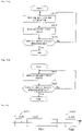
- control device 40a when taken as control blocks, control device 40a includes moving section 44 and guide section 45. Control device 40a executes control programs in accordance with flowcharts shown in Figs. 5a and 5b .
- Fig. 5a shows an example of a control procedure for a receiving operation of supply component 9S and device 9F.
- Control device 40a acquires identification information of supply component 9S using acquisition device 40d when supply component 9S is received in via first opening section 41a (Step S11). Similarly, control device 40a can also acquire identification information of device 9F using acquisition device 40d when device 9F is received in via first opening section 41a.
- control device 40a can also acquire specific information of accommodation case 93 using acquisition device 40d when accommodation case 93 is received in via first opening section 41a. In this case, control device 40a acquires the identification information of at least one of supply component 9S and device 9F which is accommodated in accommodation case 93 based on the correspondence between the specific information and the identification information. In any of the cases, control device 40a causes the storage device to store the acquired identification information.
- moving section 44 causes moving device 40b to move supply component 9S to predetermined first storage section 42a for storage therein (Step S12). Similarly, moving section 44 can also cause moving device 40b to move device 9F to predetermined second storage section 42b for storage therein. In addition, moving section 44 can also cause moving device 40b to move supply component 9S and device 9F to predetermined third storage section 42c for storage therein. Further, moving section 44 can also cause moving device 40b to move accommodation case 93 to predetermined storage section 42 for storage therein. In any of the cases, control device 40a causes the storage device to store the positional information and the receiving dates and times of supply component 9S and device 9F.
- control device 40a determines whether all supply components 9S and devices 9F that are scheduled to be received in storage cabinet 40 have been so received (step S13). If all supply components 9S and devices 9F that are scheduled to be received in storage cabinet 40 have been so received (if Yes in Step S13), control device 40a ends temporarily the control for the receiving operation. If all supply components 9S and devices 9F that are scheduled to be received in storage cabinet 40 have not yet been so received (if NO in Step S13), control device 40a returns to the operation in Step S11 for the receiving operation. Then, control device 40a repeats the operations shown in Steps S11 to S13 until all supply components 9S and devices 9F that are scheduled to be received in storage cabinet 40 have been so received.
- Fig. 5b shows an example of a control procedure for a delivery operation of supply component 9S and device 9F.
- the production plan is managed by, for example, management device 19, and management device 19 transmits a delivery command of delivering supply component 9S and device 9F which are to be used for identical unit production UJ0 to storage cabinet 40 based on the production plan.
- storage cabinet 40 associates supply component 9S and device 9F with each other for use for specified identical unit production UJ0 and then delivers that supply component 9S and that device 9F which are so associated with each other.
- moving section 44 moves supply component 9S stored in first storage section 42 to delivery section 43 and moves device 9F stored in second storage section 42b to delivery section 43.
- moving section 44 can also move supply component 9S stored in first storage section 42a to first delivery section 43a and move device 9F stored in second storage section 42b to second delivery section 43b.
- moving section 44 causes moving device 40b to move supply component 9S stored in first storage section 42a to delivery space 40f and then to move that supply component 9S moved to delivery space 40f to first delivery section 43a.
- moving section 44 causes moving device 40b to move device 9F stored in second storage section 42b to delivery space 40f and then to move that device 9F moved to delivery space 40f to second delivery section 43b (step S21).
- Moving section 44 can also cause moving device 40b to move accommodation case 93 stored in storage section 42 to delivery space 40f and then to move that accommodation case 93 moved to delivery space 40f to delivery section 43.
- control device 40a causes the storage device to store the delivery dates and times of supply component 9S and device 9F.
- control device 40a determines whether all supply components 9S and devices 9F that are scheduled to be delivered out from storage cabinet 40 have been so delivered out (Step S22). If control device 40a determines that all supply components 9S and devices 9F that are scheduled to be delivered out from storage cabinet 40 have been so delivered out (Yes in Step S22), control device 40a ends temporarily the control for delivery operation. If control device 40a determines that all supply components 9S and devices 9F that are scheduled to be delivered out from storage cabinet 40 have not yet been so delivered out (No in Step S22), control device 40a returns to the operation in Step S21. Then, control device 40a repeats the operations shown in Steps S21 and S22 until all supply components 9S and devices 9F that are scheduled to be delivered out from storage cabinet 40 have been so delivered out.
- first unit production UJ1 one unit production UJ0 in which board products 900 are produced by board work machine 10 is referred to as first unit production UJ1.
- second unit production UJ2 at least one unit production UJ0 which is carried out after first unit production UJ1 on is referred to as second unit production UJ2.
- first unit production UJ1 since board products 900 are produced by board work machine 10, device 9F has already been mounted in board work machine 10. Therefore, there are fewer delivery requests for device 9F in first unit production UJ1 than in second unit production UJ2.
- moving section 44 can move supply component 9S and device 9F which are used for second unit production UJ2. Specifically speaking, moving section 44 causes moving device 40b to move supply component 9S and device 9F which are used for second production UJ2 based on a delivery command received from management device 19.
- Storage cabinet 40 of the present embodiment includes guide section 45.
- Guide section 45 notifies the operator of first delivery section 43a from which supply component 9S for use for second unit production UJ2 is delivered out and second delivery section 43b from which device 9F for use for second unit production UJ2 is delivered out. As a result, the operator can easily recognize supply component 9S and device 9F which are used for second unit production UJ2.
- Guide section 45 need only notify the operator of first delivery section 43a and second delivery section 43b, and hence, guide section 45 can take various forms.
- guide section 45 can display the positions of those first delivery section 43a and second delivery section 43b which are formed into rack 47 by use of display device 40e shown in Fig. 3a .
- guide section 45 can also display the positions of those first delivery section 43a and second delivery section 43b which are formed into rack 47 by use of a display device which is provided on rack 47.
- guide section 45 displays an indicator in the vicinity of the upper space of rack 47 indicating that the upper space is a delivery location for supply component 9S, whereby guide section 45 notifies that that first delivery section 43a is formed in the upper space of rack 47.
- guide section 45 displays an indicator in the vicinity of the lower space of rack 47 indicating that the lower space is a delivery location for device 9F, whereby guide section 45 notifies that that second delivery section 43b is formed in the lower space of rack 47.
- first unit production UJ1 since board products 900 are produced by board work machine 10, there is a possibility of, for example, occurrence of a shortage of components accommodated in reel 91a (a shortage of supply components 9S).
- management device 19 transmits a delivery command of delivering supply components 9S required to storage cabinet 40.
- storage cabinet 40 delivers out supply components 9S so required.
- moving section 44 causes moving device 40b to move supply component 9S which is used for first unit production UJ1 to first delivery section 43a.
- moving section 44 causes moving device 40b to move supply component 9S which is used for first unit production UJ1 to first delivery section 43a based on a delivery command received from management device 19.
- guide section 45 need only notify of first delivery section 43a from which supply component 9S which is used for first unit production UJ1 is delivered out and first delivery section 43a from which supply component 9S which is used for second unit production UJ2 is delivered out in a distinguishable fashion.
- guide section 45 can notify through display that a part of the upper space of rack 47 shown in Fig. 7a is allocated for the current production to thereby notify the operator that supply component S9 which is used for first unit production UJ1 is delivered to the space so allocated.
- guide section 45 can notify through display that the remainder of the upper space of rack 47 shown in Fig. 7a is allocated for a subsequent production to thereby notify the operator that supply component 9S which is used for second unit production UJ2 is delivered to the space so allocated.
- the operator can identify to distinguish first delivery section 43a from which supply component 9S which is used for first unit production UJ1 is delivered out from first delivery section 43a from which supply component 9S which is used for second unit production UJ2 is delivered out.
- moving section 44 can also causes moving device 40b to move device 9F which is used for first unit production UJ1 to second delivery section 43b.
- guide section 45 need only notify the operator of second delivery section 43b from which device 9F which is used for first unit production UJ1 is delivered out and second delivery section 43b from which device 9F which is used for second unit production UJ2 is delivered out in a distinguishable fashion.
- guide section 45 can notify through display that a portion of the lower space of rack 47 shown in Fig. 7a is allocated for the current production to thereby notify the operator that device 9F which is used for first unit production UJ1 is delivered to the space so allocated.
- guide section 45 can notify through display that the remainder of the lower space of rack 47 shown in Fig. 7a is allocated for a subsequent production to thereby notify the operator that device 9F which is used for second unit production UJ2 is delivered to the space so allocated.
- the operator can identify to distinguish second delivery section 43b from which device 9F which is used for first unit production UJ1 is delivered out from second delivery section 43b from which device 9F which is used for second unit production UJ2 is delivered out.
- partition plate 49 can be provided in rack 47.
- Partition plate 49 provided in first delivery section 43a shown in Fig. 7a divides first delivery section 43a into first delivery section 43a from which supply component 9S which is used for first unit production UJ1 is delivered out and first delivery section 43a from which supply component 9S which is used for second unit production UJ2 is delivered out.
- partition plate 49 provided in second delivery section 43b divides second delivery section 43b into second delivery section 43b from which device 9F which is used for first unit production UJ1 is delivered out and second delivery section 43b from which device 9F which is used for second unit production UJ2 is delivered out.
- guide section 45 similarly applies wheeled table 46 shown in Fig. 7b and also similarly applies to forms shown in Figs. 7c and 7d .
- guide section 45 need only notify the operator of first delivery section 43a from which supply component 9S which is used for unit production UJ0 occurring subsequent to first unit production UJ1 is delivered out and first delivery section 43a from which supply component 9S which is used for unit production UJ0 occurring subsequent to unit production UJ0 occurring subsequent to first unit production UJ1 is delivered out in a distinguishable fashion.
- guide section 45 notifies through display that the remainder of the upper space of rack 47 shown in Fig. 7a is allocated for a subsequent production and a production after the subsequent production on instead of notifying that the remainder of the upper space of rack 47 is allocated for the subsequent production.
- the operator can identify to distinguish first delivery section 43a from which supply component 9S which is used for unit production UJ0 subsequent to first unit production UJ1 is delivered out from first delivery section 43a from which supply component 9S which is used for unit production UJ0 occurring subsequent to unit production UJ0 occurring subsequent to first unit production UJ1 is delivered out.
- Partition plate 49 can also be provided in each of these first delivery sections 43a.
- guide section 45 need only notify the operator of second delivery section 43b from which device 9F which is used for unit production UJ0 occurring subsequent to first unit production UJ1 is delivered out and second delivery section 43b from which device 9F which is used for unit production UJ0 occurring subsequent to unit production UJ0 occurring subsequent to first unit production UJ1 is delivered out in a distinguishable fashion.
- guide section 45 notifies through display that the remainder of the lower space of rack 47 shown in Fig. 7a is allocated for a subsequent production and a production after the subsequent production on instead of notifying that the remainder of the lower space of rack 47 is allocated for the subsequent production.
- the operator can identify to distinguish second delivery section 43b from which device 9F which is used for unit production UJ0 subsequent to first unit production UJ1 is delivered out from second delivery section 43b from which device 9F which is used for unit production UJ0 occurring subsequent to unit production UJ0 occurring subsequent to first unit production UJ1 is delivered out.
- Partition plate 49 can also be provided in each of these second delivery sections 43b.
- first production time slot TM1 at least one unit production UJ0 of second unit production UJ2 is performed.
- second production time slot TM2 occurs later than first production time slot TM1, and in second production time slot TM2, at least one unit production UJ0 of the other unit productions UJ0 of second unit production UJ2 is performed.
- guide section 45 notifies that the remainder of the upper space of rack 47 shown in Fig. 7a is allocated for a production in first production time slot TM1 and a production in second production time slot TM2 instead of notifying that the remainder of the upper space of rack 47 is allocated for a subsequent production.
- the operator can identify to distinguish first delivery section 43a from which supply component 9S which is used for first production time slot TM1 is delivered out from first delivery section 43a from which supply component 9S which is used for second production time slot TM2 is delivered out.
- Partition plate 49 can also be provided in each of these first delivery sections 43a.
- guide section 45 need only notify of second delivery section 43b from which device 9F which is used for first production time slot TM1 is delivered out and second delivery section 43b from which device 9F which is used for second production time slot TM2 is delivered out in a distinguishable fashion.
- guide section 45 notifies that the remainder of the lower space of rack 47 shown in Fig. 7a is allocated for a production in first production time slot TM1 and a production in second production time slot TM2 instead of notifying that the remainder of the lower space of rack 47 is allocated for a subsequent production.
- the operator can identify to distinguish second delivery section 43b from which device 9F which is used for first production time slot TM1 is delivered out from second delivery section 43b from which device 9F which is used for second production time slot TM2 is delivered out.
- Partition plate 49 can also be provided in each of these second delivery sections 43b.
- first delivery section 43a and second delivery section 43b are formed into rack 47 which can hold supply component 9S and device 9F.
- first delivery section 43a and second delivery section 43b can be formed into wheeled table 46 which can hold supply component 9S and device 9F.
- wheeled table 46 includes a similar configuration to that of rack 47 described above.
- wheeled table 46 can adopt, for example, a conveyance vehicle similar to conveyance vehicle 30, which may be an unmanned conveyance vehicle or may be pulled by the operator.
- First delivery section 43a and second delivery section 43b can also be formed into multiple wheeled tables 46 or multiple racks 47.
- multiple first delivery sections 43a may be formed, or multiple second delivery sections 43b may be formed, respectively.
- first delivery section 43a needs to be identified, and second delivery section 43b needs to be identified.
- first identification section 48a for identifying first delivery section 43a and second identification section 48b for identifying second delivery section 43b need only be provided on wheeled table 46 or rack 47.
- First identification section 48a need only identify first delivery section 43a and hence can take various forms.
- second identification section 48b need only identify second delivery section 43b and hence can take various forms.
- First identification section 48a and second identification section 48b can each adopt, for example, a one-dimensional code, a two-dimensional code, a wireless tag, or the like.
- First identification section 48a and second identification section 48b may be a form of notification by guide section 45.
- first delivery section 43a may be formed into first wheeled table 46a which can hold supply component 9S
- second delivery section 43b may be formed into second wheeled table 46b which can hold device 9F.
- first identification section 48a for identifying first delivery section 43a need only be provided on first wheeled table 46a
- second identification section 48b for identifying second delivery section 43b need only be provided on second wheeled table 46b.
- first delivery section 43a may be formed into first rack 47a which can hold supply component 9S
- second delivery section 43b may be formed into second rack 47b which can hold device 9F.
- first identification section 48a for identifying first delivery section 43a need only be provided on first rack 47a
- second identification section 48b for identifying second delivery section 43b need only be provided on second rack 47b.
- storage cabinet 40 and the operator can identify first delivery section 43a and can identify second delivery section 43b.
- supply component 9S and device 9F are delivered out while being associated with each other by way of second opening section 41b.
- supply component 9S and device 9F can also be delivered out while being associated with each other by way of first opening section 41a.
- moving section 44 can cause moving device 40b to deliver out accommodation case 93 which accommodates supply component 9S and device 9F by way of first opening section 41a.
- a conveyance device can also be provided outside storage cabinet 40. In this case, the conveyance device conveys supply component 9S delivered out by way of first opening section 41a to delivery section 43. The conveyance device conveys device 9F delivered out by way of first opening section 41a to delivery section 43.
- the conveyance device can convey supply component 9S delivered out by way of first opening section 41a to first delivery section 43a.
- the conveyance device can convey device 9F delivered out by way of first opening section 41a to second delivery section 43b.
- the conveyance device can convey accommodation case 93, accommodating at least one of supply component 9S and device 9F, which is delivered out by way of first opening section 41a to delivery section 43.
- delivery section 43 is not limited to the form in which the exclusive delivery sections are defined as with first delivery section 43a and second delivery section 43b.
- Delivery section 43 may take, for example, a form in which a location corresponding to first delivery section 43a and a location corresponding to second delivery section 43b are mixed together.
- storage cabinet 40 may adopt a configuration in which delivery section 43 is divided for each identical unit production UJ0 and supply component 9S and device 9F which are used for identical unit production UJ0 are delivered individually to the divided sections.
- delivery section 43 may be configured so that only supply component 9S and device 9F which are used for one unit production UJ0 are delivered out, while supply component 9S and device 9F which are used for another unit production UJ0 are not delivered out at the same time.
- storage cabinet 40 With storage cabinet 40, storage cabinet 40 includes first storage section 42a, second storage section 42b, delivery section 43, and moving section 44. As a result, with storage cabinet 40, supply component 9S can be stored in first storage section 42, and device 9F can be stored in second storage section 42b. In addition, with storage cabinet 40, moving section 44 causes supply component 9S stored in first storage section 42a to be delivered to delivery section 43 and causes device 9F stored in second storage section 42b to be delivered to delivery section 43, and delivery section 43 can deliver out supply component 9S and device 9F which are used for predetermined unit projection UJ0 therefrom in an associated fashion.
- 10 board work machine, 10c: component mounter, 40: storage cabinet, 42a: first storage section, 42b:second storage section, 43: delivery section, 43a: first delivery section, 43b: second delivery section, 44: moving section, 45: guide section, 46: wheeled table, 46a: first wheeled table, 46b: second wheeled table, 47: rack, 47a: first rack, 47b: second rack, 48a: first identification section, 48b: second identification section, 90: board, 91: article, 93: accommodation case, 95c: holding member, 9S: supply component, 9F: device, 900: board product, UJ0: unit production, UJ1: first unit production, UJ2: second unit production, TM1: first production time slot, TM2: second production time slot
Landscapes
- Engineering & Computer Science (AREA)
- Manufacturing & Machinery (AREA)
- Microelectronics & Electronic Packaging (AREA)
- Operations Research (AREA)
- Supply And Installment Of Electrical Components (AREA)
- General Factory Administration (AREA)
Abstract
Description
- The present description discloses a technology relating to a storage cabinet.
- A storage cabinet described in Patent Literature 1 stores a mounting head and a feeder device. In addition, in an exchange supporting apparatus described in Patent Literature 1, when a setup change is carried out to change the types of boards to be produced, the exchange supporting apparatus determines a mounting head and a feeder device which are to be mounted on a component mounter from mounting heads and feeder devices which are stored in the storage cabinet based on production job information and maintenance information. The exchange supporting apparatus searches for a feeder device which holds a reel accommodating a type of components needed for a production after the setup change. Further, a guide section of the exchange supporting apparatus informs an operator of a mounting head and a feeder device which are to be delivered from the storage cabinet.
- In a nozzle managing machine of Patent Literature 2, a setting control section sets a suction nozzle required by a component mounter on a nozzle tray based on information received from at least one of the component mounter and a management device.
-
- Patent Literature 1:
JP-A-2017-37886 - Patent Literature 2: International Publication No.
WO2014/069016 - For production of board products using a board work machine, both a supply component such as an article or the like which is mounted on a board by the board work machine and a device which is detachably provided on the board work machine for use in board work are necessary. In addition, since a combination of supply component and device necessary for production of board products changes as the type of board products to be produced changes, a supply component and a device which match a type of board products to be produced become necessary. Further, when a supply component and a device are stored in such a state that the supply component is incorporated in the device as with the reel and the feeder device described above, combinations of a supply component and a device for delivery are limited.
- In view of these situations, according to the present description, there is disclosed a storage cabinet which can store a supply component and a device separately and which can deliver a supply component and a device for use for a unit production which specifies a production of an identical type of board products in an associated fashion.
- The present description discloses a storage cabinet including a first storage section, a second storage section, a delivery section, and a moving section. The first storage section stores a supply component which is at least one of an article which is provided on a board by a board work machine configured to perform predetermined board work on the board and the board before the article is provided thereon. The second storage section stores a device which is detachably provided on the board work machine for use in the board work. The delivery section delivers the supply component and the device in an associated fashion which are used for a predetermined unit production included in a production plan which prescribes an order of unit productions which each specify a production of an identical type of board products using the board work machine. The moving section moves the supply component stored in the first storage section to the delivery section and moves the device stored in the second storage section to the delivery section.
- With the configuration of the storage cabinet described above, the storage cabinet includes the first storage section, the second storage section, the delivery section, and the moving section. As a result, the storage cabinet can store the supply component in the first storage section and the device in the second storage section. In addition, with the storage cabinet described above, the moving section moves the supply component stored in the first storage section to the delivery section and moves the device stored in the second storage section to the delivery section, whereby the delivery section can deliver the supply component and the device in the associated fashion for use in the predetermined unit production.
-
-
Fig. 1 is a schematic view showing a configuration example of a board production facility. -
Fig. 2 is a plan view showing an example of a state in which supply components and devices are accommodated in accommodation cases at an arrival section. -
Fig. 3a is a front view showing an example of a storage cabinet. -
Fig. 3b is a plan view of the storage cabinet shown inFig. 3a . -
Fig. 3c is a front view showing an example of a storage section of the storage cabinet shown inFig. 3b . -
Fig. 4 is a block diagram showing an example of control blocks of the storage cabinet. -
Fig. 5a is a flowchart showing an example of a control procedure for a receiving operation of a supply component and a device. -
Fig. 5b is a flowchart showing an example of a control procedure for a delivery operation of a supply component and a device. -
Fig. 6 is a schematic diagram showing an example of a relationship among a first unit production, a second unit production, a first production time slot, and a second production time slot. -
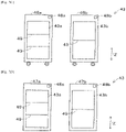
Fig. 7a is a schematic diagram showing a configuration example of a delivery section in which a first delivery section and a second delivery section are both formed into a rack. -
Fig. 7b is a schematic diagram showing a configuration example of a delivery section in which a first delivery section and a second delivery section are both formed into a wheeled table. -
Fig. 7c is a schematic diagram showing a configuration example of a delivery section in which a first delivery section is formed into a first wheeled table and a second delivery section is formed into a second wheeled table. -
Fig. 7d is a schematic diagram showing a configuration example of a delivery section in which a first delivery section is formed into a first rack and a second delivery section is formed into a second rack. - As shown in
Fig. 1 ,storage cabinet 40 of an embodiment of the present description is provided inboard production facility 80.Board production facility 80 includesboard working line 10L,arrival section 20,conveyance vehicle 30, andstorage cabinet 40. - In
board working line 10L, predetermined board work is performed onboard 90. The type and number of board work machines 10 constitutingboard working line 10L are not limited. As shown inFig. 1 ,board working line 10L of the present embodiment includes multiple (five) board work machines 10 such as printer 10a, printing inspection machine 10b, component mounter 10c, reflow furnace 10d, and appearance inspection machine 10e, andboard 90 is conveyed sequentially in this order by a board conveyance device. - Printer 10a prints solder in multiple component mounting positions on
board 90. Solder that is printed onboard 90 has a predetermined viscosity, and the solder so printed functions as a bonding material forbonding board 90 and a component that is mounted onboard 90 together. As shown inFig. 2 , solder is accommodated insolder accommodation container 91c. For example, a bottomed cylindrical or tubular sealable container can be used assolder accommodation container 91c. - Printing inspection machine 10b inspects a print state of solder which is printed by printer 10a. Component mounter 10c mounts multiple components on
board 90 on which solder is printed. Component mounter 10c may be provided one, or multiple component mounters 10c may be provided. In the case that multiple component mounters 10c are provided, those multiple component mounters 10c can share a mounting operation for mounting multiple components onboard 90. - Component mounter 10c includes a component supply device for supplying components which are mounted on
board 90. The component supply device can supply components using, for example,feeder 95b including reel 91a,tray 91b, and the like which are shown inFig. 2 . A component tape (a carrier tape) which accommodates components thereon is wound aroundreel 91a.Reel 91a is rotatably and detachably provided infeeder 95b, and a distal end portion of the component tape is drawn out to a component take-out or pickup section provided infeeder 95b, whereby components are sequentially supplied.Reel 91a can supply, for example, a relatively small component such as a chip component. - Multiple components are arranged on
tray 91b.Tray 91b can supply a relatively large component such as, for example, a Quad Flat Package (QFP), a Ball Grid Array (BGA), and the like. The component supply device can also supply, for example, components accommodated inparts accommodating container 91d. Multiple components are accommodated inparts accommodating container 91d without being arranged. - Further, mounting
head 95a is detachably (in an exchangeable fashion) provided on component mounter 10c. At least one holdingmember 95c is provided detachably (in an exchangeable fashion) provided on mountinghead 95a. For example, a suction nozzle, a chuck, or the like can be used as holdingmember 95c. Component mounter 10c picks up and holds a component supplied by the component supply device and mounts the component onboard 90, which is positioned, by use of mountinghead 95a and holdingmember 95c. - Holding
member 95c can be changed as required in accordance with the type of a component to be mounted in a mounting process of mounting a component onboard 90. For example, in the case that holdingmember 95c for use for a mounting process to be executed is not attached to mountinghead 95a of component mounter 10c, holdingmember 95c accommodated in holding memberaccommodating device 95d can be attached to mountinghead 95a. Holding memberaccommodating device 95d is capable of accommodating multiple holdingmembers 95c in a detachable (exchangeable) fashion and is installed in a predetermined position inside component mounter 10c in a detachable (exchangeable) fashion. - Reflow furnace 10d heats
board 90 on which multiple components are mounted by component mounter 10c to melt the solder printed thereon for soldering. Appearance inspection machine 10e inspects the mounting state or the like of the multiple components mounted onboard 90 by component mounter 10c. In this way, inboard working line 10L,board 90 is conveyed sequentially so that the production processes including the inspection process can be executed thereon for production ofboard product 900 by use of multiple (five) board work machines 10s.Board working line 10L can also include, as required, board work machines 10 such as, for example, a function inspection machine, a buffer device, a board supply device, a board flipping device, a shield mounting device, an adhesive application device, an ultraviolet ray irradiation device, and the like. - Multiple (five) board work machines 10 and
management device 19, which make upboard working line 10L, are provided so as to be capable of communicating with each other by a wired or wireless communication section.Management device 19 controls multiple (five) board work machines 10, which make upboard working line 10L, to monitor operation situations ofboard working line 10L.Management device 19 stores various control data for controlling multiple (five) board work machines 10.Management device 19 transmits the control data to each of multiple (five) board work machines 10. On the other hand, each of multiple (five) board work machines 10 transmits an operation situation and a production situation tomanagement device 19. - In the present description, at least one of
article 91 which is provided onboard 90 by board work machine 10, which is configured to perform predetermined board work onboard 90, andboard 90 on which anyarticle 91 has not yet been mounted will be referred to assupply component 9S. In addition, a thing which is detachably provided on board work machine 10 for use for board work will be referred to asdevice 9F. - As has been described above,
board working line 10L includes printer 10a. In this case, for example, solder accommodated insolder accommodation container 91c corresponds toarticle 91. In addition, for example, in the case of printer 10a configured to execute a printing process onboard 90 by moving solder along a mask by a squeegee, the squeegee and the mask correspond todevice 9F. Further, for example, in the case of a printer configured to apply solder on each of multiple printing positions onboard 90 by a printing head, the printing head and a dispense head correspond todevice 9F. - In addition,
board working line 10L includes component mounter 10c. In this case, for example, a component accommodated in a component tape wound aroundreel 91a corresponds toarticle 91. A component accommodated ontray 91b corresponds toarticle 91. A component accommodated inparts accommodating container 91d corresponds toarticle 91. Mountinghead 95a which is detachably provided on component mounter 10c corresponds todevice 9F.Feeder 95b which is detachably provided in component mounter 10c corresponds todevice 9F. Holdingmember 95c which is detachably provided on component mounter 10c via mountinghead 95a corresponds todevice 9F. Holding memberaccommodating device 95d which is detachably provided in component mounter 10c corresponds todevice 9F. - Further,
board working line 10L includes printing inspection machine 10b. In addition,board working line 10L includes appearance inspection machine 10e. In these cases, for example, an inspection head for inspecting an inspection target object (solder or a component) corresponds todevice 9F.Board 90 on which anyarticle 91 has not yet been mounted is conveyed to printer 10a shown inFig. 1 . Thatboard 90 is included insupply component 9S. - When
supply component 9S arrives atarrival section 20, predetermined landing work is performed. Then,supply component 9S is accommodated inaccommodation case 93, and thisaccommodation case 93 is mounted onconveyance vehicle 30 and is conveyed tostorage cabinet 40. Oncesupply component 9S is stored instorage cabinet 40,supply component 9S is then supplied to board workingline 10L as required. - As shown in
Fig. 2 ,identification code 92 is provided onsupply component 9S.Identification code 92 stores identification information for identifyingsupply component 9S. For example, a one-dimensional code, a two-dimensional code, a wireless tag, or the like can be used foridentification code 92. Whensupply component 9S arrives atarrival section 20, an operator atarrival section 20 issues identification information using, for example, the management device. In addition, the operator reads a barcode or the like which is provided onsupply component 9S by a supplier (a vendor) using a barcode reader or the like. Then, the operator can also obtain supply component information forsupply component 9S from a database in which the supply information forsupply component 9S is registered. The operator stores at least the identification information of the identification information and the supply component information inidentification code 92 using the management device. - The operator at
arrival section 20 attachesidentification code 92 which stores at least the identification information therein to supplycomponent 9S and accommodates thatsupply component 9S inaccommodation case 93.Accommodation case 93 need only accommodate at least onesupply component 9S and hence can take various forms.Specific code 94 is provided onaccommodation case 93.Specific code 94 stores specific information for specifyingaccommodation case 93. For example, a one-dimensional code, a two-dimensional code, a wireless tag, or the like can be used forspecific code 94. - When accommodating
supply component 9S inaccommodation case 93, the operator readsspecific code 94 using the reader and readsidentification code 92 provided on thatsupply component 9S using the reader. As a result, a correspondence between the specific information which specifiesaccommodation case 93accommodating supply component 9S and the identification information which identifies thatsupply component 9S is generated, and the correspondence so generated is transmitted to and stored in a storage section ofmanagement device 19. What is described above onsupply component 9S also applies to a case in whichdevice 9F arrives atarrival section 20. -
Fig. 2 is a plan view showing an example of an accommodation state in whichsupply component 9S anddevice 9F are accommodated inaccommodation case 93. Specifically speaking,Fig. 2 shows an example of a state in whichreel 91a around which a component tape accommodating a component corresponding toarticle 91 is wound is accommodated inaccommodation case 93. In addition,Fig. 2 shows an example of a state in whichtrays 91b each accommodating a component corresponding toarticle 91 are accommodated (loaded) inaccommodation case 93.Tray 91b is accommodated in a packaging bag, andidentification code 92 is attached to the packaging bag oftray 91b. Further,Fig. 2 shows an example of a state in which solderaccommodation containers 91c each accommodating solder corresponding toarticle 91 are accommodated inaccommodation case 93. In addition,Fig. 2 shows an example of a state in whichsubstrate 90 on which anyarticle 91 has not yet been provided is accommodated d inaccommodation case 93. - Further,
Fig. 2 shows an example of a state in which mountinghead 95a,feeder 95b, holdingmember 95c, and holding memberaccommodating device 95d, which each correspond todevice 9F, are accommodated individually in correspondingaccommodation cases 93. Mountinghead 95a andfeeder 95b are individually accommodated in correspondingaccommodation cases 93. Holdingmember 95c can be accommodated in an accommodation space which accommodates detachably holdingmember 95c and can also be accommodated detachably in holding memberaccommodating device 95d. -
Accommodation case 93 can also accommodatesupply component 9S anddevice 9F together. For example,parts accommodating containers 91d, each accommodating a component corresponding toarticle 91, and holding memberaccommodating device 95d and holdingmembers 95c, each corresponding todevice 9F, are accommodated together inaccommodation case 93 shown inFig. 2 . In either of the cases, a shock absorbing member is provided inaccommodation case 93, whereby vibration or the like which would be applied to supplycomponents 9S anddevice 9F during conveyance or the like is reduced. - The operator at
arrival section 20 mountsaccommodation case 93 which accommodates therein at least one ofsupply component 9S anddevice 9F onconveyance vehicle 30. For example, the operator can pullconveyance vehicle 30. In addition, for example, a self-propelled unmanned conveyance vehicle (an automated guided vehicle (AGV)), which does not have to be pulled by the operator, can also be used forconveyance vehicle 30. In the present embodiment,conveyance vehicle 30 adopts an unmanned conveyance vehicle. -
Board working line 10L,arrival section 20,conveyance vehicle 30, andstorage cabinet 40 are provided so as to be capable of communicating with each other by a wired or wireless communication section. Whenaccommodation case 93 which accommodates at least one ofsupply component 9S anddevice 9F is mounted onconveyance vehicle 30,management device 19 transmits a conveyance command toconveyance vehicle 30. The conveyance command includes a conveyance destination of thataccommodation case 93.Management device 19 selectsstorage cabinet 40 which can store thataccommodation case 93 and determines a conveyance destination. When receiving the conveyance command,conveyance vehicle 30 conveys thataccommodation case 93 tostorage cabinet 40 which is designated as the conveyance destination. -
Conveyance vehicle 30 can also convey at least one ofsupply component 9S anddevice 9F without usingaccommodation case 93. In addition, the operator can convey at least one ofsupply component 9S anddevice 9F without usingconveyance vehicle 30. Further, at least a part of the work described as being performed by the operator can be automated using a conveyance device (for example, a belt conveyor), an actuator (for example, a robot arm and the like.), the management device, or the like. - In this way, at least one of
supply component 9S anddevice 9F that have arrived atarrival section 20 is conveyed tostorage cabinet 40. In addition, at least one ofsupply component 9S anddevice 9F which become unnecessary inboard working line 10L is conveyed tostorage cabinet 40.Supply component 9S anddevice 9F which are conveyed tostorage cabinet 40 are stored instorage cabinet 40 and are then conveyed to board workingline 10L as required. -
Storage cabinet 40 need onlystore supply component 9S anddevice 9F, and hence,storage cabinet 40 can take various forms. As shown inFigs. 3a and 3b ,storage cabinet 40 of the present embodiment is formed in, for example, an octagonal prism shape. As shown inFigs. 3a to 3c ,storage cabinet 40 includesfirst opening section 41a,second opening section 41b,storage section 42,delivery section 43,control device 40a, and movingdevice 40b.Storage section 42 includesfirst storage section 42a andsecond storage section 42b and can further includethird storage section 42c.Delivery section 43 includesfirst delivery section 43a andsecond delivery section 43b.Delivery portion 43 can be formed into, for example, wheeled table 46 orrack 47. - Further, as shown in
Fig. 4 , when taken as a control block,control device 40a includes movingsection 44.Control device 40a can further includeguide section 45. In addition,storage cabinet 40 can include at least one ofwork space 40c,acquisition device 40d,display device 40e, and delivery space 40f. As shown inFigs. 3a to 3c and4 , in the present embodiment,storage cabinet 40 includes all the parts and devices described above.Delivery section 43 is formed intorack 47. - As shown in
Figs. 3a and 3b ,first opening section 41a is provided in a front surface ofstorage cabinet 40, andsecond section 41b is provided in a side surface ofstorage cabinet 40.Supply component 9S anddevice 9F are received in and delivered out fromfirst opening section 41a.First opening section 41a is formed larger thansupply component 9S anddevice 9F so thatsupply component 9S anddevice 9F can be received in and delivered out fromfirst opening section 41a. - At least one of
supply component 9S anddevice 9F can be received in and delivered out viafirst opening section 41a while being accommodated inaccommodation case 93. In this case,first opening section 41a is formed larger thanaccommodation case 93 so thataccommodation case 93 can be received in and delivered out fromfirst opening section 41a.Supply component 9S anddevice 9F are delivered out fromsecond opening section 41b. What is described above aboutfirst opening section 41a will be true withsecond opening section 41b. - In addition,
acquisition device 40d is provided infirst opening section 41a.Acquisition device 40d readsidentification code 92 provided onsupply component 9S and acquires the identification information for identifyingsupply component 9S Similarly,acquisition device 40d readsidentification code 92 provided ondevice 9F and acquires the identification information for identifyingdevice 9F. A known reader (for example, a code reader for reading a one-dimensional code and a two-dimensional code, a wireless reader for performing wireless communication with a wireless tag, or the like) can be used foracquisition device 40d. - As shown in
Figs. 3a and 3b ,acquisition device 40d is set abovework space 40c provided in the vicinity offirst opening section 41a.Acquisition device 40d readsidentification code 92 provided onsupply component 9S to acquire at least the identification information of the identification information and the supply component information whensupply component 9S is received in viafirst opening section 41a. Similarly,acquisition device 40d readsidentification code 92 provided ondevice 9F to acquire at least the identification information of the identification information and the device information ondevice 9F whendevice 9F is received in viafirst opening section 41a. -
Acquisition device 40d can readspecific code 94 provided onaccommodation case 93 to acquire the specific information whenaccommodation case 93 is received in viafirst opening section 41a. In this case,acquisition device 40d can acquire the identification information of at least one ofsupply component 9S anddevice 9F which is accommodated inaccommodation case 93 based on the correspondence between the specific information and the identification information. - As a result, with
storage cabinet 40 of the present embodiment,acquisition device 40d is provided only infirst opening section 41a. In addition,first opening section 41a functions both as the receiving section and the delivery section through whichsupply component 9S anddevice 9F can be received in or delivered out, whilesecond opening section 41b functions exclusively as the delivery section throughsupply component 9S anddevice 9F can be delivered out. -
Storage section 42 need only store bothsupply component 9S anddevice 9F and hence can take various forms. As shown inFig. 3b ,storage section 42 of the present embodiment is disposed in a circular shape when viewed in a vertical direction (a Z-axis direction). As shown inFig. 3c ,storage section 42 includesfirst storage sections 42a each configured to storesupply component 9S andsecond storage sections 42b each configured to storedevice 9F. - The numbers and arrangements of
first storage sections 42a andsecond storage sections 42b are changed as required. For example, at least onestorage section 42 ofmultiple storage sections 42 can include onlyfirst storage section 42a, while at least onestorage section 42 of theother storage sections 42 ofmultiple storage sections 42 can include onlysecond storage section 42b. As shown inFig. 3b , instorage cabinet 40 of the present embodiment, a part offirst storage sections 42a orsecond storage sections 42b is eliminated so as to securework space 40c and delivery space 40f. - Further, the shape and size (width, depth, and height) of
first storage section 42a can be set so as to matchsupply component 9S to be stored therein, and the shape and size (width, depth, and height) ofsecond storage section 42b can be set so as to matchdevice 9F to be stored therein. In addition,storage section 42 can also storeaccommodation case 93 which accommodates at least one ofsupply component 9S anddevice 9F therein. - In this case, the shapes and sizes (width, depth, and height) of
first storage section 42a andsecond storage section 42b can be set so as to matchaccommodation case 93. On the contrary, the shape and size (width, depth, and height) ofaccommodation case 93 can be set so as to match the shapes and sizes offirst storage section 42a andsecond storage section 42b. - As shown in
Fig. 3c ,storage section 42 can also includethird storage sections 42c which each store bothsupply component 9s anddevice 9F.Accommodation case 93 which accommodates bothsupply component 9S anddevice 9F (in whichdevice 9F andsupply component 9S are accommodated together) is stored inthird storage section 42c. In addition,supply component 9S,device 9F, andaccommodation case 93 can also be stored insuitable storage sections 42. In this case,storage section 42 wheresupply component 9S is stored isfirst storage section 42a.Storage section 42 wheredevice 9F is stored issecond storage section 42b.Storage section 42 where bothsupply component 9S anddevice 9F are stored isthird storage section 42c. In the case thatboard production facility 80 includesmultiple storage cabinets 40,supply component 9S,device 9F, andaccommodation case 93 may be stored in anystorage cabinets 40, as long as thosestorage cabinets 40 includesuitable storage sections 42. - A production plan prescribes an order of unit productions UJ0 which each specify a production of an identical type of
board products 900 using board work machines 10. For example, the production plan prescribes a production of multiple types (for example, three types) ofboard products 900 as in a production order of a production of a first type ofboard products 900, a production of a second type ofboard products 900, a production of a third type ofboard products 900, and the like. In addition, the production plan can also include a production number ofboard product 900 to be produced, a production period, a delivery time,supply component 9S anddevice 9F which are to be used, and the like. Further, in the case that there exist multipleboard working lines 10L which can be used for production, the production plan can also include board working line orlines 10L for use for production. The production plan may be a production plan for one type ofboard products 900. -
Delivery section 43 delivers outsupply component 9S anddevice 9F in associated fashion which are to be used for a predetermined unit production UJ0 included in the production plan. In the present embodiment,delivery section 43 includesfirst delivery section 43a andsecond delivery section 43b.Supply component 9S for use for unit production UJ0 is delivered tofirst delivery section 43a.Device 9F for use for unit production UJ0 which usessupply component 9S delivered out fromfirst storage section 43a is delivered tosecond delivery section 43b. -
First delivery section 43a andsecond delivery section 43b can be formed into, for example, wheeled table 46 orrack 47 which can holdsupply component 9S anddevice 9F. Wheeled table 46 orrack 47 need only holdsupply component 9S anddevice 9F, and hence, wheeled table 46 andrack 47 can take various forms. As shown inFig. 3a , in the present embodiment,first delivery section 43a andsecond delivery section 43b are formed intorack 47 which includes multiple storage spaces. - For example,
first storage section 43a is formed in an upper space ofrack 47, whilesecond delivery section 43b is formed in a lower space ofrack 47. A door portion is provided insecond opening section 41b shown inFig. 3b . The upper space and the lower space ofrack 47 can communicate with delivery space 40f viasecond opening section 41b. Specifically speaking, the door portion is caused to be in an open state bycontrol device 40a whensupply component 9S anddevice 9F are delivered out. Then,supply component 9S anddevice 9F which are used for identical unit production UJ0 are delivered out in an associated fashion by way ofsecond opening section 41b. Whensupply component 9S anddevice 9F are so delivered out, the door portion is caused to be in a closed state bycontrol device 40a. -
Control device 40a includes a known arithmetic unit and a storage device, as well as a control circuit which is configured therein.Control device 40a is provided so as to be capable of communicating with movingdevice 40b,acquisition device 40d, anddisplay device 40e and can control these devices. In addition,control device 40a can also cause a door portion provided infirst opening section 41a and the door portion provided insecond opening section 41b to be opened and closed. Further,control device 40a can store supply information onsupply component 9S and can also notifymanagement device 19 of the supply component information. - For example, in the case that
supply component 9S isreel 91a, the supply information can include a type of a component accommodated inreel 91a, the number of components (the number of remaining components), a reel diameter, a reel model type, and a reel supplier (vendor), an expiration date, and the like. Similarly,control device 40a can store device information ondevice 9F and can also notifymanagement device 19 of the device information. For example, in the case thatdevice 9F is mountinghead 95a, the device information can include the number of times of use of mountinghead 95a, the duration of use of mountinghead 95a, component mounter 10c which uses mountinghead 95a, the maintenance time of mountinghead 95a, and the like. - When
supply component 9S is received instorage cabinet 40 viafirst opening section 41a, movingdevice 40b movessupply component 9S so received to predeterminedfirst storage section 42a, and whensupply component 9S is delivered out, movingdevice 40b movessupply component 9S stored infirst storage section 42a to delivery space 40f. Similarly, whendevice 9F is received instorage cabinet 40 viafirs opening section 41a, movingdevice 40b movesdevice 9F so received to predeterminedsecond storage section 42b, and whendevice 9F is delivered out, movingdevice 40b movesdevice 9F stored insecond storage section 42b to delivery space 40f. - The same applies when
accommodation case 93 which accommodates at least one ofsupply component 9S anddevice 9F is received instorage cabinet 40 by way offirst opening section 41a. That is, whenaccommodation case 93 is received in by way offirst opening section 41a, movingdevice 40b movesaccommodation case 93 so received to predeterminedfirst storage section 42a,second storage section 42b orthird storage section 42c. In addition, whenaccommodation case 93 is delivered out, movingdevice 40b movesaccommodation case 93 stored infirst storage section 42a,second storage section 42b orthird storage section 42c to delivery space 40f. - As shown in
Fig. 3b , movingdevice 40b of the present embodiment is provided radially inwards ofstorage section 42 as viewed in the vertical direction (the Z-axis direction). Movingdevice 40b need only be able to move a target object (supply component 9S anddevice 9F or accommodation case 93) and hence can take various forms. For example, a robot arm (an articulated robot), a lifting and lowering slide mechanism, and the like can be used for movingdevice 40b. - Moving
device 40b can include, for example, a raising/lowering section 40b1 and gripping section 40b2. Raising/lowering section 40b1 can rotate around an axis extending along the vertical direction (the Z-axis direction) and can raise or lower gripping section 40b2 along the vertical direction (the Z-axis direction). Gripping section 40b2 can advance or retreat and can hold or release a hold of a target object. As a result, movingdevice 40b can store a target object that is received in by way offirst opening section 41a instorage section 42 and can move the target object to delivery space 40f. In addition, movingdevice 40b can also move the target object moved to delivery space 40f todelivery section 43. Further, movingdevice 40b can include a conveyance device (that is, a belt conveyor or the like) in delivery space 40f. In this case, the conveyance device can move the target object moved to delivery space 40f todelivery section 43. - When delivering
supply component 9s, movingdevice 40b can also movesupply component 9S stored infirst storage section 42a to workspace 40c provided infirst opening section 41a. Similarly, when deliveringdevice 9F, movingdevice 40b can movedevice 9F stored insecond storage section 42b to workspace 40c provided infirst opening section 41a. In addition, when delivering bothsupply component 9S anddevice 9F, movingdevice 40b can movesupply component 9S anddevice 9F which are stored inthird storage section 42c to workspace 40c provided infirst opening section 41a. What is described above applies to a case in which at least one ofsupply component 9S anddevice 9F is accommodated inaccommodation case 93. - With
storage cabinet 40 of the present embodiment, at least one ofsupply component 9S anddevice 9F is stored while being accommodated inaccommodation case 93 and is delivered out while being accommodated inaccommodation case 93. As a result, at least one ofsupply component 9S anddevice 9F which is accommodated inaccommodation case 93 can easily be moved, and hence, irrespective of types ofsupply component 9S anddevice 9F, gripping section 40b2 of movingdevice 40b can easily be shared with. In addition, at least one ofsupply component 9S anddevice 9F can easily be managed to thereby reduce a risk of being lost or the like by storing and delivering at least one ofsupply component 9S anddevice 9F while being accommodated inaccommodation case 93. - As has been described above,
accommodation case 93 can accommodate various types ofsupply components 9S and can accommodate various types ofdevices 9F. In addition,accommodation case 93 can also accommodate bothsupply component 9S anddevice 9F (can accommodatedevice 9F andsupply component 9S together). For example, let's assume a case in which board work machine 10 is component mount 10c for mounting a component, which issupply component 9S, onboard 90, which issupply component 9S. In this case, for example, since there exists a case in which the use of holdingmember 95c for holding a component is limited depending on a type of component, there may be a case in which a component and holdingmember 95c for holding the component are preferably managed together. In this case, holdingmember 95c, which isdevice 9F for picking up to hold a component and mounting the component onboard 90, and a component which can be held by holdingmember 95c need only be accommodated together inaccommodation case 93. In this way,device 9F andsupply component 9S need only be accommodated together inaccommodation case 93 as the degree at whichsupply component 9S anddevice 9F are related to each other (the degree of association) becomes higher. - As shown in
Fig. 3a ,storage cabinet 40 includesdisplay device 40e. A know display device can be used fordisplay device 40e, and thisdisplay device 40e displays various types of data in such a way that the operator can visually recognize them.Display device 40e displays, for example, supply component information onsupply component 9S stored infirst storage section 42a, device information ondevice 9F stored insecond storage section 42b, and the like in response to an operation by the operator. - In addition,
control device 40a can store positional information, receiving and delivery information and storage information onsupply component 9S anddevice 9F instorage section 42, anddisplay device 40e can also display these pieces of information. The positional information indicates storage locations ofsupply component 9S anddevice 9F. The receiving and delivery information indicates receiving date and time and delivery date and time of each ofsupply component 9S anddevice 9F. The storage information includes, for example, information on the ambient temperature instorage section 42, the humidity instorage section 42, and the like.Control device 40a stores positional information and receiving date and time of each ofsupply component 9S anddevice 9F when thatsupply component 9S and thatdevice 9F are received to be stored.Control device 40a stores storage information onsupply component 9S anddevice 9F while thatsupply component 9S and thatdevice 9F are being stored.Control device 40a stores delivery date and time of each ofsupply component 9S anddevice 9F when thatsupply component 9S and thatdevice 9F are delivered out. -
Display device 40e of the present embodiment is made up of a touch panel, anddisplay device 40e also functions as an input device for receiving various types of operations by the operator. For example, the operator can also specifysupply component 9S anddevice 9F which are desired to be delivered out fromstorage cabinet 40 by use of the touch panel (display device 40e functioning as the input device). In this case,storage cabinet 40 delivers outsupply component 9S anddevice 9F which are so specified. - As shown in
Fig. 4 , when taken as control blocks,control device 40a includes movingsection 44 andguide section 45.Control device 40a executes control programs in accordance with flowcharts shown inFigs. 5a and 5b . -
Fig. 5a shows an example of a control procedure for a receiving operation ofsupply component 9S anddevice 9F.Control device 40a acquires identification information ofsupply component 9S usingacquisition device 40d whensupply component 9S is received in viafirst opening section 41a (Step S11). Similarly,control device 40a can also acquire identification information ofdevice 9F usingacquisition device 40d whendevice 9F is received in viafirst opening section 41a. - In addition,
control device 40a can also acquire specific information ofaccommodation case 93 usingacquisition device 40d whenaccommodation case 93 is received in viafirst opening section 41a. In this case,control device 40a acquires the identification information of at least one ofsupply component 9S anddevice 9F which is accommodated inaccommodation case 93 based on the correspondence between the specific information and the identification information. In any of the cases,control device 40a causes the storage device to store the acquired identification information. - Next, moving
section 44causes moving device 40b to movesupply component 9S to predeterminedfirst storage section 42a for storage therein (Step S12). Similarly, movingsection 44 can also cause movingdevice 40b to movedevice 9F to predeterminedsecond storage section 42b for storage therein. In addition, movingsection 44 can also cause movingdevice 40b to movesupply component 9S anddevice 9F to predeterminedthird storage section 42c for storage therein. Further, movingsection 44 can also cause movingdevice 40b to moveaccommodation case 93 topredetermined storage section 42 for storage therein. In any of the cases,control device 40a causes the storage device to store the positional information and the receiving dates and times ofsupply component 9S anddevice 9F. - Next,
control device 40a determines whether allsupply components 9S anddevices 9F that are scheduled to be received instorage cabinet 40 have been so received (step S13). If allsupply components 9S anddevices 9F that are scheduled to be received instorage cabinet 40 have been so received (if Yes in Step S13),control device 40a ends temporarily the control for the receiving operation. If allsupply components 9S anddevices 9F that are scheduled to be received instorage cabinet 40 have not yet been so received (if NO in Step S13),control device 40a returns to the operation in Step S11 for the receiving operation. Then,control device 40a repeats the operations shown in Steps S11 to S13 until allsupply components 9S anddevices 9F that are scheduled to be received instorage cabinet 40 have been so received. -
Fig. 5b shows an example of a control procedure for a delivery operation ofsupply component 9S anddevice 9F. The production plan is managed by, for example,management device 19, andmanagement device 19 transmits a delivery command of deliveringsupply component 9S anddevice 9F which are to be used for identical unit production UJ0 tostorage cabinet 40 based on the production plan. When receiving the delivery command,storage cabinet 40associates supply component 9S anddevice 9F with each other for use for specified identical unit production UJ0 and then delivers thatsupply component 9S and thatdevice 9F which are so associated with each other. - Specifically speaking, moving
section 44 movessupply component 9S stored infirst storage section 42 todelivery section 43 and movesdevice 9F stored insecond storage section 42b todelivery section 43. In addition, movingsection 44 can also movesupply component 9S stored infirst storage section 42a tofirst delivery section 43a and movedevice 9F stored insecond storage section 42b tosecond delivery section 43b. In the present embodiment, movingsection 44causes moving device 40b to movesupply component 9S stored infirst storage section 42a to delivery space 40f and then to move thatsupply component 9S moved to delivery space 40f tofirst delivery section 43a. - In addition, moving
section 44causes moving device 40b to movedevice 9F stored insecond storage section 42b to delivery space 40f and then to move thatdevice 9F moved to delivery space 40f tosecond delivery section 43b (step S21). Movingsection 44 can also cause movingdevice 40b to moveaccommodation case 93 stored instorage section 42 to delivery space 40f and then to move thataccommodation case 93 moved to delivery space 40f todelivery section 43. In any of the cases,control device 40a causes the storage device to store the delivery dates and times ofsupply component 9S anddevice 9F. - Next,
control device 40a determines whether allsupply components 9S anddevices 9F that are scheduled to be delivered out fromstorage cabinet 40 have been so delivered out (Step S22). Ifcontrol device 40a determines that allsupply components 9S anddevices 9F that are scheduled to be delivered out fromstorage cabinet 40 have been so delivered out (Yes in Step S22),control device 40a ends temporarily the control for delivery operation. Ifcontrol device 40a determines that allsupply components 9S anddevices 9F that are scheduled to be delivered out fromstorage cabinet 40 have not yet been so delivered out (No in Step S22),control device 40a returns to the operation in Step S21. Then,control device 40a repeats the operations shown in Steps S21 and S22 until allsupply components 9S anddevices 9F that are scheduled to be delivered out fromstorage cabinet 40 have been so delivered out. - Here, one unit production UJ0 in which
board products 900 are produced by board work machine 10 is referred to as first unit production UJ1. In addition, as shown inFig. 6 , at least one unit production UJ0 which is carried out after first unit production UJ1 on is referred to as second unit production UJ2. In first unit production UJ1, sinceboard products 900 are produced by board work machine 10,device 9F has already been mounted in board work machine 10. Therefore, there are fewer delivery requests fordevice 9F in first unit production UJ1 than in second unit production UJ2. - Then, as a mode in which
delivery section 43 delivers outsupply component 9S anddevice 9F in an associated fashion, a case is assumed in whichsupply component 9S anddevice 9F are delivered out for use for second unit production UJ2. In this case, movingsection 44 can movesupply component 9S anddevice 9F which are used for second unit production UJ2. Specifically speaking, movingsection 44causes moving device 40b to movesupply component 9S anddevice 9F which are used for second production UJ2 based on a delivery command received frommanagement device 19. -
Storage cabinet 40 of the present embodiment includesguide section 45.Guide section 45 notifies the operator offirst delivery section 43a from whichsupply component 9S for use for second unit production UJ2 is delivered out andsecond delivery section 43b from whichdevice 9F for use for second unit production UJ2 is delivered out. As a result, the operator can easily recognizesupply component 9S anddevice 9F which are used for second unit production UJ2. -
Guide section 45 need only notify the operator offirst delivery section 43a andsecond delivery section 43b, and hence, guidesection 45 can take various forms. For example, guidesection 45 can display the positions of thosefirst delivery section 43a andsecond delivery section 43b which are formed intorack 47 by use ofdisplay device 40e shown inFig. 3a . In addition, as shown inFig. 7a , guidesection 45 can also display the positions of thosefirst delivery section 43a andsecond delivery section 43b which are formed intorack 47 by use of a display device which is provided onrack 47. - Specifically speaking,
guide section 45 displays an indicator in the vicinity of the upper space ofrack 47 indicating that the upper space is a delivery location forsupply component 9S, wherebyguide section 45 notifies that thatfirst delivery section 43a is formed in the upper space ofrack 47. Similarly, guidesection 45 displays an indicator in the vicinity of the lower space ofrack 47 indicating that the lower space is a delivery location fordevice 9F, wherebyguide section 45 notifies that thatsecond delivery section 43b is formed in the lower space ofrack 47. - In first unit production UJ1, since
board products 900 are produced by board work machine 10, there is a possibility of, for example, occurrence of a shortage of components accommodated inreel 91a (a shortage ofsupply components 9S). In the case that a shortage ofsupply components 9S occurs, or in the case that there is a possibility of a shortage ofsupply components 9S,management device 19 transmits a delivery command of deliveringsupply components 9S required tostorage cabinet 40. Upon receipt of the delivery command,storage cabinet 40 delivers outsupply components 9S so required. - In this case, moving
section 44causes moving device 40b to movesupply component 9S which is used for first unit production UJ1 tofirst delivery section 43a. Specifically speaking, movingsection 44causes moving device 40b to movesupply component 9S which is used for first unit production UJ1 tofirst delivery section 43a based on a delivery command received frommanagement device 19. In this case, guidesection 45 need only notify offirst delivery section 43a from whichsupply component 9S which is used for first unit production UJ1 is delivered out andfirst delivery section 43a from whichsupply component 9S which is used for second unit production UJ2 is delivered out in a distinguishable fashion. - Specifically speaking,
guide section 45 can notify through display that a part of the upper space ofrack 47 shown inFig. 7a is allocated for the current production to thereby notify the operator that supply component S9 which is used for first unit production UJ1 is delivered to the space so allocated. In addition,guide section 45 can notify through display that the remainder of the upper space ofrack 47 shown inFig. 7a is allocated for a subsequent production to thereby notify the operator that supplycomponent 9S which is used for second unit production UJ2 is delivered to the space so allocated. As a result, the operator can identify to distinguishfirst delivery section 43a from whichsupply component 9S which is used for first unit production UJ1 is delivered out fromfirst delivery section 43a from whichsupply component 9S which is used for second unit production UJ2 is delivered out. - As has been described above, although there are fewer delivery requests for
device 9F in first unit production UJ1 than in second unit production UJ2, there is also a possibility of occurrence of a necessity ofnew device 9F in first unit production UJ1 due to, for example, a failure ofdevice 9F currently in use. Therefore, as in the case withsupply component 9S, movingsection 44 can also causes movingdevice 40b to movedevice 9F which is used for first unit production UJ1 tosecond delivery section 43b. In this case, guidesection 45 need only notify the operator ofsecond delivery section 43b from whichdevice 9F which is used for first unit production UJ1 is delivered out andsecond delivery section 43b from whichdevice 9F which is used for second unit production UJ2 is delivered out in a distinguishable fashion. - Specifically speaking,
guide section 45 can notify through display that a portion of the lower space ofrack 47 shown inFig. 7a is allocated for the current production to thereby notify the operator thatdevice 9F which is used for first unit production UJ1 is delivered to the space so allocated. In addition,guide section 45 can notify through display that the remainder of the lower space ofrack 47 shown inFig. 7a is allocated for a subsequent production to thereby notify the operator thatdevice 9F which is used for second unit production UJ2 is delivered to the space so allocated. As a result, the operator can identify to distinguishsecond delivery section 43b from whichdevice 9F which is used for first unit production UJ1 is delivered out fromsecond delivery section 43b from whichdevice 9F which is used for second unit production UJ2 is delivered out. - In addition,
partition plate 49 can be provided inrack 47.Partition plate 49 provided infirst delivery section 43a shown inFig. 7a dividesfirst delivery section 43a intofirst delivery section 43a from whichsupply component 9S which is used for first unit production UJ1 is delivered out andfirst delivery section 43a from whichsupply component 9S which is used for second unit production UJ2 is delivered out. In addition,partition plate 49 provided insecond delivery section 43b dividessecond delivery section 43b intosecond delivery section 43b from whichdevice 9F which is used for first unit production UJ1 is delivered out andsecond delivery section 43b from whichdevice 9F which is used for second unit production UJ2 is delivered out. What is described aboutguide section 45 similarly applies wheeled table 46 shown inFig. 7b and also similarly applies to forms shown inFigs. 7c and 7d . - There may be a case in which the operator has difficulty in distinguishing
supply component 9S which is used for last unit production UJ0 fromsupply component 9S which is used for unit production UJ0 which is carried out after the last unit production UJ0 on. Then, guidesection 45 need only notify the operator offirst delivery section 43a from whichsupply component 9S which is used for unit production UJ0 occurring subsequent to first unit production UJ1 is delivered out andfirst delivery section 43a from whichsupply component 9S which is used for unit production UJ0 occurring subsequent to unit production UJ0 occurring subsequent to first unit production UJ1 is delivered out in a distinguishable fashion. - Specifically speaking,
guide section 45 notifies through display that the remainder of the upper space ofrack 47 shown inFig. 7a is allocated for a subsequent production and a production after the subsequent production on instead of notifying that the remainder of the upper space ofrack 47 is allocated for the subsequent production. As a result, the operator can identify to distinguishfirst delivery section 43a from whichsupply component 9S which is used for unit production UJ0 subsequent to first unit production UJ1 is delivered out fromfirst delivery section 43a from whichsupply component 9S which is used for unit production UJ0 occurring subsequent to unit production UJ0 occurring subsequent to first unit production UJ1 is delivered out.Partition plate 49 can also be provided in each of thesefirst delivery sections 43a. - What is described on
supply component 9S similarly applies todevice 9F. Then, guidesection 45 need only notify the operator ofsecond delivery section 43b from whichdevice 9F which is used for unit production UJ0 occurring subsequent to first unit production UJ1 is delivered out andsecond delivery section 43b from whichdevice 9F which is used for unit production UJ0 occurring subsequent to unit production UJ0 occurring subsequent to first unit production UJ1 is delivered out in a distinguishable fashion. - Specifically speaking,
guide section 45 notifies through display that the remainder of the lower space ofrack 47 shown inFig. 7a is allocated for a subsequent production and a production after the subsequent production on instead of notifying that the remainder of the lower space ofrack 47 is allocated for the subsequent production. As a result, the operator can identify to distinguishsecond delivery section 43b from whichdevice 9F which is used for unit production UJ0 subsequent to first unit production UJ1 is delivered out fromsecond delivery section 43b from whichdevice 9F which is used for unit production UJ0 occurring subsequent to unit production UJ0 occurring subsequent to first unit production UJ1 is delivered out.Partition plate 49 can also be provided in each of thesesecond delivery sections 43b. - In addition, there may be a case in which the operator wants to identify to distinguish
supply component 9S which is used for a predetermined production time slot (for example, a morning production for board products 900) fromsupply component 9S which is used for a production time slot (for example, an afternoon production for board products 900) occurring after the predetermined production time slot. Then, guidesection 45 need only notify offirst delivery section 43a from whichsupply component 9S which is used for first production time slot TM1 is delivered out andfirst delivery section 43a from whichsupply component 9S which is used for second production time slot TM2 is delivered out in a distinguishable fashion. In first production time slot TM1, at least one unit production UJ0 of second unit production UJ2 is performed. As shown inFig. 6 , second production time slot TM2 occurs later than first production time slot TM1, and in second production time slot TM2, at least one unit production UJ0 of the other unit productions UJ0 of second unit production UJ2 is performed. - In this mode, guide
section 45 notifies that the remainder of the upper space ofrack 47 shown inFig. 7a is allocated for a production in first production time slot TM1 and a production in second production time slot TM2 instead of notifying that the remainder of the upper space ofrack 47 is allocated for a subsequent production. As a result, the operator can identify to distinguishfirst delivery section 43a from whichsupply component 9S which is used for first production time slot TM1 is delivered out fromfirst delivery section 43a from whichsupply component 9S which is used for second production time slot TM2 is delivered out.Partition plate 49 can also be provided in each of thesefirst delivery sections 43a. - What is described on
supply component 9S similarly applies todevice 9F. Then, guidesection 45 need only notify ofsecond delivery section 43b from whichdevice 9F which is used for first production time slot TM1 is delivered out andsecond delivery section 43b from whichdevice 9F which is used for second production time slot TM2 is delivered out in a distinguishable fashion. - In this mode, guide
section 45 notifies that the remainder of the lower space ofrack 47 shown inFig. 7a is allocated for a production in first production time slot TM1 and a production in second production time slot TM2 instead of notifying that the remainder of the lower space ofrack 47 is allocated for a subsequent production. As a result, the operator can identify to distinguishsecond delivery section 43b from whichdevice 9F which is used for first production time slot TM1 is delivered out fromsecond delivery section 43b from whichdevice 9F which is used for second production time slot TM2 is delivered out.Partition plate 49 can also be provided in each of thesesecond delivery sections 43b. - In the present embodiment,
first delivery section 43a andsecond delivery section 43b are formed intorack 47 which can holdsupply component 9S anddevice 9F. For example,first delivery section 43a andsecond delivery section 43b can be formed into wheeled table 46 which can holdsupply component 9S anddevice 9F. As shown inFig. 7b , wheeled table 46 includes a similar configuration to that ofrack 47 described above. In addition, wheeled table 46 can adopt, for example, a conveyance vehicle similar toconveyance vehicle 30, which may be an unmanned conveyance vehicle or may be pulled by the operator. -
First delivery section 43a andsecond delivery section 43b can also be formed into multiple wheeled tables 46 ormultiple racks 47. In addition, in one wheeled table 46 or onerack 47, multiplefirst delivery sections 43a may be formed, or multiplesecond delivery sections 43b may be formed, respectively. In either of the cases,first delivery section 43a needs to be identified, andsecond delivery section 43b needs to be identified. Then,first identification section 48a for identifyingfirst delivery section 43a andsecond identification section 48b for identifyingsecond delivery section 43b need only be provided on wheeled table 46 orrack 47. -
First identification section 48a need only identifyfirst delivery section 43a and hence can take various forms. Similarly,second identification section 48b need only identifysecond delivery section 43b and hence can take various forms.First identification section 48a andsecond identification section 48b can each adopt, for example, a one-dimensional code, a two-dimensional code, a wireless tag, or the like.First identification section 48a andsecond identification section 48b may be a form of notification byguide section 45. - In addition, as shown in
Fig. 7c ,first delivery section 43a may be formed into first wheeled table 46a which can holdsupply component 9S, andsecond delivery section 43b may be formed into second wheeled table 46b which can holddevice 9F. In this case,first identification section 48a for identifyingfirst delivery section 43a need only be provided on first wheeled table 46a, andsecond identification section 48b for identifyingsecond delivery section 43b need only be provided on second wheeled table 46b. - Further, as shown in
Fig. 7d ,first delivery section 43a may be formed intofirst rack 47a which can holdsupply component 9S, andsecond delivery section 43b may be formed intosecond rack 47b which can holddevice 9F. In this case,first identification section 48a for identifyingfirst delivery section 43a need only be provided onfirst rack 47a, andsecond identification section 48b for identifyingsecond delivery section 43b need only be provided onsecond rack 47b. In either of the cases,storage cabinet 40 and the operator can identifyfirst delivery section 43a and can identifysecond delivery section 43b. - With
storage cabinet 40 of the embodiment,supply component 9S anddevice 9F are delivered out while being associated with each other by way ofsecond opening section 41b. However, withstorage cabinet 40,supply component 9S anddevice 9F can also be delivered out while being associated with each other by way offirst opening section 41a. For example, movingsection 44 can cause movingdevice 40b to deliver outaccommodation case 93 which accommodatessupply component 9S anddevice 9F by way offirst opening section 41a. In addition, a conveyance device can also be provided outsidestorage cabinet 40. In this case, the conveyance device conveyssupply component 9S delivered out by way offirst opening section 41a todelivery section 43. The conveyance device conveysdevice 9F delivered out by way offirst opening section 41a todelivery section 43. In addition, the conveyance device can conveysupply component 9S delivered out by way offirst opening section 41a tofirst delivery section 43a. The conveyance device can conveydevice 9F delivered out by way offirst opening section 41a tosecond delivery section 43b. In addition, the conveyance device can conveyaccommodation case 93, accommodating at least one ofsupply component 9S anddevice 9F, which is delivered out by way offirst opening section 41a todelivery section 43. - In addition,
delivery section 43 is not limited to the form in which the exclusive delivery sections are defined as withfirst delivery section 43a andsecond delivery section 43b.Delivery section 43 may take, for example, a form in which a location corresponding tofirst delivery section 43a and a location corresponding tosecond delivery section 43b are mixed together. In this case,storage cabinet 40 may adopt a configuration in whichdelivery section 43 is divided for each identical unit production UJ0 andsupply component 9S anddevice 9F which are used for identical unit production UJ0 are delivered individually to the divided sections. In addition,delivery section 43 may be configured so thatonly supply component 9S anddevice 9F which are used for one unit production UJ0 are delivered out, whilesupply component 9S anddevice 9F which are used for another unit production UJ0 are not delivered out at the same time. - With
storage cabinet 40,storage cabinet 40 includesfirst storage section 42a,second storage section 42b,delivery section 43, and movingsection 44. As a result, withstorage cabinet 40,supply component 9S can be stored infirst storage section 42, anddevice 9F can be stored insecond storage section 42b. In addition, withstorage cabinet 40, movingsection 44 causessupply component 9S stored infirst storage section 42a to be delivered todelivery section 43 and causesdevice 9F stored insecond storage section 42b to be delivered todelivery section 43, anddelivery section 43 can deliver outsupply component 9S anddevice 9F which are used for predetermined unit projection UJ0 therefrom in an associated fashion. - 10: board work machine, 10c: component mounter, 40: storage cabinet, 42a: first storage section, 42b:second storage section, 43: delivery section, 43a: first delivery section, 43b: second delivery section, 44: moving section, 45: guide section, 46: wheeled table, 46a: first wheeled table, 46b: second wheeled table, 47: rack, 47a: first rack, 47b: second rack, 48a: first identification section, 48b: second identification section, 90: board, 91: article, 93: accommodation case, 95c: holding member, 9S: supply component, 9F: device, 900: board product, UJ0: unit production, UJ1: first unit production, UJ2: second unit production, TM1: first production time slot, TM2: second production time slot
Claims (14)
- A storage cabinet comprising:a first storage section configured to store a supply component which is at least one of an article which is provided on a board by a board work machine configured to perform predetermined board work on the board and the board before the article is provided thereon;a second storage section configured to store a device which is detachably provided on the board work machine for use in the board work;a delivery section configured to deliver the supply component and the device in an associated fashion which are used for a predetermined unit production included in a production plan which prescribes an order of unit productions which each specify a production of an identical type of board products using the board work machine; anda moving section configured to move the supply component stored in the first storage section to the delivery section and moves the device stored in the second storage section to the delivery section.
- The storage cabinet according to claim 1,
wherein at least one of the supply component and the device is stored in such a state that the at least one is accommodated in an accommodation case and is delivered out in such a state that the at least one is accommodated in the accommodation case. - The storage cabinet according to claim 2,
wherein the device and the supply component are accommodated together in the accommodation case. - The storage cabinet according to claim 3,wherein the board work machine is a component mounter configured to mount a component, which is the supply component, on the board, which is the supply component, andwherein a holding member, which is the device and is configured to pick up, hold, and mount the component on the board, and the component, which can be held by the holding member, are accommodated together in the accommodation case.
- The storage cabinet according any one of claims 1 to 4,
wherein the moving section is configured to move the supply component and the device which are used for a second unit projection which is at least one of the unit productions occurring subsequent to a first unit production which is one of the unit productions in which the board products are produced by the board work machine. - The storage cabinet according to claim 5,
wherein the delivery section comprises:a first delivery section from which the supply component which is used for the unit production is delivered out; anda second delivery section from which the device which is used for the unit production is delivered out, the unit production being identical to the unit production in which the supply component is used. - The storage cabinet according to claim 6, further comprising:
a guide section configured to notify an operator of the first delivery section from which the supply component which is used for the second unit production is delivered out and the second delivery section from which the device which is used for the second unit production is delivered out. - The storage cabinet according to claim 7,
wherein the guide section notifies of the first delivery section from which the supply component which is used for the unit production subsequent to the first unit production is delivered out and the first delivery section from which the supply component which is used for the unit production occurring subsequent to the unit production occurring subsequent to the first unit production is delivered out in a distinguishable fashion. - The storage cabinet according to claim 7 or 8,
wherein the guide section notifies of the second delivery section from which the device which is used for the unit production subsequent to the first unit production is delivered out and the second delivery section from which the device which is used for the unit production occurring subsequent to the unit production occurring subsequent to the first unit production is delivered out in a distinguishable fashion. - The storage cabinet according to claim 7,
wherein the guide section notifies of the first delivery section from which the supply component which is used for a first production time slot, in which at least one of the unit productions of the second unit production is performed, is delivered out and the first delivery section from which the supply component which is used for a second production time slot, which occurs later than the first production time slot and in which at least one unit production of the other unit productions of the second unit production is performed, is delivered out in a distinguishable fashion. - The storage as claimed in claim 7 or claim 8,
wherein the guide section notifies of the second delivery section from which the device which is used for a first production time slot, in which at least one of the unit productions of the second unit production is performed, is delivered out and the second delivery section from which the device which is used for a second production time slot, which occurs later than the first production time slot and in which at least one unit production of the other unit productions of the second unit production is performed, is delivered out in a distinguishable fashion. - The storage cabinet according to any one of claims 7 to 11,wherein the moving section moves the supply component which is used for the first unit production to the first delivery section, andwherein the guide section notifies of the first delivery section from which the supply component which is used for the first unit production is delivered out and the first delivery section from which the supply component which is used for the second unit production is delivered out in a distinguishable fashion.
- The storage cabinet according to any one of claims 1 to 12,
wherein the delivery section comprises:a first delivery section from which the supply component which is used for the unit production is delivered out; anda second delivery section from which the device which is used for the unit production identical to the unit production for which the supply component delivered out from the first delivery section is used is delivered out,wherein the first delivery section and the second delivery section are formed into a wheeled table or a rack which can hold the supply component and the device, andwherein a first identification section configured to identify the first delivery section and a second identification section configured to identify the second delivery section are provided on the wheeled table or the rack. - The storage cabinet according to any one of claims 1 to 12,
wherein the delivery section comprises:a first delivery section from which the supply component which is used for the unit production is delivered out; anda second delivery section from which the device which is used for the unit production identical to the unit production for which the supply component delivered out from the first delivery section is used is delivered out,wherein the first delivery section is formed into a first wheeled table or a first rack which can hold the supply component,wherein the second delivery section is formed into a second wheeled table or a second rack which can hold the device,wherein a first identification section configured to identify the first delivery section is provided on the first wheeled table or the first rack, andwherein a second identification section configured to identify the second delivery section is provided on the second wheeled table or the second rack.
Applications Claiming Priority (1)
| Application Number | Priority Date | Filing Date | Title |
|---|---|---|---|
| PCT/JP2019/040079 WO2021070339A1 (en) | 2019-10-10 | 2019-10-10 | Storage cabinet |
Publications (3)
| Publication Number | Publication Date |
|---|---|
| EP4044784A1 true EP4044784A1 (en) | 2022-08-17 |
| EP4044784A4 EP4044784A4 (en) | 2022-10-19 |
| EP4044784B1 EP4044784B1 (en) | 2025-02-19 |
Family
ID=75437826
Family Applications (1)
| Application Number | Title | Priority Date | Filing Date |
|---|---|---|---|
| EP19948516.0A Active EP4044784B1 (en) | 2019-10-10 | 2019-10-10 | Storage cabinet |
Country Status (3)
| Country | Link |
|---|---|
| EP (1) | EP4044784B1 (en) |
| JP (1) | JP7281552B2 (en) |
| WO (1) | WO2021070339A1 (en) |
Families Citing this family (2)
| Publication number | Priority date | Publication date | Assignee | Title |
|---|---|---|---|---|
| JPWO2023132081A1 (en) * | 2022-01-07 | 2023-07-13 | ||
| JPWO2024161633A1 (en) * | 2023-02-03 | 2024-08-08 |
Family Cites Families (7)
| Publication number | Priority date | Publication date | Assignee | Title |
|---|---|---|---|---|
| JP2005244175A (en) * | 2004-01-27 | 2005-09-08 | Matsushita Electric Ind Co Ltd | Management method and system for equipment requiring maintenance management |
| KR102135007B1 (en) | 2012-10-30 | 2020-07-16 | 가부시키가이샤 후지 | Nozzle managing apparatus |
| JP6739152B2 (en) | 2015-08-07 | 2020-08-12 | 株式会社Fuji | Exchange support device |
| JP6817005B2 (en) * | 2016-09-23 | 2021-01-20 | ヤマハ発動機株式会社 | Parts supply system, autonomous bogie and parts supply method |
| WO2018127956A1 (en) * | 2017-01-05 | 2018-07-12 | 株式会社Fuji | System for managing component mounting line |
| EP3738908B1 (en) * | 2018-01-12 | 2024-07-31 | Fuji Corporation | Storage device and storage method |
| JP2019182561A (en) * | 2018-04-03 | 2019-10-24 | 株式会社東芝 | Program and picking system |
-
2019
- 2019-10-10 EP EP19948516.0A patent/EP4044784B1/en active Active
- 2019-10-10 WO PCT/JP2019/040079 patent/WO2021070339A1/en not_active Ceased
- 2019-10-10 JP JP2021551052A patent/JP7281552B2/en active Active
Also Published As
| Publication number | Publication date |
|---|---|
| EP4044784B1 (en) | 2025-02-19 |
| EP4044784A4 (en) | 2022-10-19 |
| JP7281552B2 (en) | 2023-05-25 |
| WO2021070339A1 (en) | 2021-04-15 |
| JPWO2021070339A1 (en) | 2021-04-15 |
Similar Documents
| Publication | Publication Date | Title |
|---|---|---|
| JP2024012692A (en) | Automatic exchange system and automatic exchange method | |
| CN112106460B (en) | Parts storage number management system and parts storage number management method | |
| EP3738908B1 (en) | Storage device and storage method | |
| EP4044784B1 (en) | Storage cabinet | |
| JP7105915B2 (en) | Storage and storage equipment with it | |
| JP7153805B2 (en) | Simulation device and simulation method | |
| JP7266113B2 (en) | Storehouse | |
| EP4032834B1 (en) | Storage | |
| JP7661368B2 (en) | Reel storage trays and storage units | |
| US12626580B2 (en) | Component notification device, feeder rack, and component notification method | |
| EP4048044B1 (en) | Storeroom | |
| JP7227990B2 (en) | Article management device and article management method | |
| JP7312904B2 (en) | parts warehouse | |
| US20250120057A1 (en) | Article management device and article management method | |
| JP2024164341A (en) | Product Guidance System | |
| JP7535188B2 (en) | Sticking removal device | |
| EP4060575B1 (en) | Operation status display device and operation status display method | |
| JP7701983B2 (en) | Component management device and component management method | |
| WO2024161633A1 (en) | Automated warehouse management system and tray | |
| WO2023162082A1 (en) | Notification device and notification method | |
| WO2025109715A1 (en) | Work guidance apparatus and work guidance method | |
| WO2025052553A1 (en) | Reel management device and reel management method | |
| JP2024164342A (en) | Reel reinforcement member and automated warehouse |
Legal Events
| Date | Code | Title | Description |
|---|---|---|---|
| STAA | Information on the status of an ep patent application or granted ep patent |
Free format text: STATUS: THE INTERNATIONAL PUBLICATION HAS BEEN MADE |
|
| PUAI | Public reference made under article 153(3) epc to a published international application that has entered the european phase |
Free format text: ORIGINAL CODE: 0009012 |
|
| STAA | Information on the status of an ep patent application or granted ep patent |
Free format text: STATUS: REQUEST FOR EXAMINATION WAS MADE |
|
| 17P | Request for examination filed |
Effective date: 20220406 |
|
| AK | Designated contracting states |
Kind code of ref document: A1 Designated state(s): AL AT BE BG CH CY CZ DE DK EE ES FI FR GB GR HR HU IE IS IT LI LT LU LV MC MK MT NL NO PL PT RO RS SE SI SK SM TR |
|
| A4 | Supplementary search report drawn up and despatched |
Effective date: 20220919 |
|
| RIC1 | Information provided on ipc code assigned before grant |
Ipc: H05K 13/02 20060101ALI20220913BHEP Ipc: H05K 13/08 20060101ALI20220913BHEP Ipc: H05K 13/00 20060101AFI20220913BHEP |
|
| DAV | Request for validation of the european patent (deleted) | ||
| DAX | Request for extension of the european patent (deleted) | ||
| P01 | Opt-out of the competence of the unified patent court (upc) registered |
Effective date: 20230328 |
|
| GRAP | Despatch of communication of intention to grant a patent |
Free format text: ORIGINAL CODE: EPIDOSNIGR1 |
|
| STAA | Information on the status of an ep patent application or granted ep patent |
Free format text: STATUS: GRANT OF PATENT IS INTENDED |
|
| RIC1 | Information provided on ipc code assigned before grant |
Ipc: H05K 13/02 20060101ALI20241025BHEP Ipc: H05K 13/08 20060101ALI20241025BHEP Ipc: H05K 13/00 20060101AFI20241025BHEP |
|
| INTG | Intention to grant announced |
Effective date: 20241122 |
|
| GRAS | Grant fee paid |
Free format text: ORIGINAL CODE: EPIDOSNIGR3 |
|
| GRAA | (expected) grant |
Free format text: ORIGINAL CODE: 0009210 |
|
| STAA | Information on the status of an ep patent application or granted ep patent |
Free format text: STATUS: THE PATENT HAS BEEN GRANTED |
|
| AK | Designated contracting states |
Kind code of ref document: B1 Designated state(s): AL AT BE BG CH CY CZ DE DK EE ES FI FR GB GR HR HU IE IS IT LI LT LU LV MC MK MT NL NO PL PT RO RS SE SI SK SM TR |
|
| REG | Reference to a national code |
Ref country code: GB Ref legal event code: FG4D |
|
| REG | Reference to a national code |
Ref country code: CH Ref legal event code: EP |
|
| REG | Reference to a national code |
Ref country code: DE Ref legal event code: R096 Ref document number: 602019066361 Country of ref document: DE |
|
| REG | Reference to a national code |
Ref country code: IE Ref legal event code: FG4D |
|
| REG | Reference to a national code |
Ref country code: NL Ref legal event code: MP Effective date: 20250219 |
|
| PG25 | Lapsed in a contracting state [announced via postgrant information from national office to epo] |
Ref country code: RS Free format text: LAPSE BECAUSE OF FAILURE TO SUBMIT A TRANSLATION OF THE DESCRIPTION OR TO PAY THE FEE WITHIN THE PRESCRIBED TIME-LIMIT Effective date: 20250519 |
|
| PG25 | Lapsed in a contracting state [announced via postgrant information from national office to epo] |
Ref country code: FI Free format text: LAPSE BECAUSE OF FAILURE TO SUBMIT A TRANSLATION OF THE DESCRIPTION OR TO PAY THE FEE WITHIN THE PRESCRIBED TIME-LIMIT Effective date: 20250219 |
|
| PG25 | Lapsed in a contracting state [announced via postgrant information from national office to epo] |
Ref country code: PL Free format text: LAPSE BECAUSE OF FAILURE TO SUBMIT A TRANSLATION OF THE DESCRIPTION OR TO PAY THE FEE WITHIN THE PRESCRIBED TIME-LIMIT Effective date: 20250219 |
|
| PG25 | Lapsed in a contracting state [announced via postgrant information from national office to epo] |
Ref country code: ES Free format text: LAPSE BECAUSE OF FAILURE TO SUBMIT A TRANSLATION OF THE DESCRIPTION OR TO PAY THE FEE WITHIN THE PRESCRIBED TIME-LIMIT Effective date: 20250219 |
|
| REG | Reference to a national code |
Ref country code: LT Ref legal event code: MG9D |
|
| PG25 | Lapsed in a contracting state [announced via postgrant information from national office to epo] |
Ref country code: NO Free format text: LAPSE BECAUSE OF FAILURE TO SUBMIT A TRANSLATION OF THE DESCRIPTION OR TO PAY THE FEE WITHIN THE PRESCRIBED TIME-LIMIT Effective date: 20250519 Ref country code: IS Free format text: LAPSE BECAUSE OF FAILURE TO SUBMIT A TRANSLATION OF THE DESCRIPTION OR TO PAY THE FEE WITHIN THE PRESCRIBED TIME-LIMIT Effective date: 20250619 |
|
| PG25 | Lapsed in a contracting state [announced via postgrant information from national office to epo] |
Ref country code: NL Free format text: LAPSE BECAUSE OF FAILURE TO SUBMIT A TRANSLATION OF THE DESCRIPTION OR TO PAY THE FEE WITHIN THE PRESCRIBED TIME-LIMIT Effective date: 20250219 |
|
| PG25 | Lapsed in a contracting state [announced via postgrant information from national office to epo] |
Ref country code: HR Free format text: LAPSE BECAUSE OF FAILURE TO SUBMIT A TRANSLATION OF THE DESCRIPTION OR TO PAY THE FEE WITHIN THE PRESCRIBED TIME-LIMIT Effective date: 20250219 |
|
| PG25 | Lapsed in a contracting state [announced via postgrant information from national office to epo] |
Ref country code: PT Free format text: LAPSE BECAUSE OF FAILURE TO SUBMIT A TRANSLATION OF THE DESCRIPTION OR TO PAY THE FEE WITHIN THE PRESCRIBED TIME-LIMIT Effective date: 20250620 Ref country code: LV Free format text: LAPSE BECAUSE OF FAILURE TO SUBMIT A TRANSLATION OF THE DESCRIPTION OR TO PAY THE FEE WITHIN THE PRESCRIBED TIME-LIMIT Effective date: 20250219 |
|
| PG25 | Lapsed in a contracting state [announced via postgrant information from national office to epo] |
Ref country code: GR Free format text: LAPSE BECAUSE OF FAILURE TO SUBMIT A TRANSLATION OF THE DESCRIPTION OR TO PAY THE FEE WITHIN THE PRESCRIBED TIME-LIMIT Effective date: 20250520 Ref country code: BG Free format text: LAPSE BECAUSE OF FAILURE TO SUBMIT A TRANSLATION OF THE DESCRIPTION OR TO PAY THE FEE WITHIN THE PRESCRIBED TIME-LIMIT Effective date: 20250219 |
|
| REG | Reference to a national code |
Ref country code: AT Ref legal event code: MK05 Ref document number: 1769655 Country of ref document: AT Kind code of ref document: T Effective date: 20250219 |
|
| PG25 | Lapsed in a contracting state [announced via postgrant information from national office to epo] |
Ref country code: SE Free format text: LAPSE BECAUSE OF FAILURE TO SUBMIT A TRANSLATION OF THE DESCRIPTION OR TO PAY THE FEE WITHIN THE PRESCRIBED TIME-LIMIT Effective date: 20250219 |
|
| PG25 | Lapsed in a contracting state [announced via postgrant information from national office to epo] |
Ref country code: SM Free format text: LAPSE BECAUSE OF FAILURE TO SUBMIT A TRANSLATION OF THE DESCRIPTION OR TO PAY THE FEE WITHIN THE PRESCRIBED TIME-LIMIT Effective date: 20250219 |
|
| PG25 | Lapsed in a contracting state [announced via postgrant information from national office to epo] |
Ref country code: DK Free format text: LAPSE BECAUSE OF FAILURE TO SUBMIT A TRANSLATION OF THE DESCRIPTION OR TO PAY THE FEE WITHIN THE PRESCRIBED TIME-LIMIT Effective date: 20250219 |
|
| PG25 | Lapsed in a contracting state [announced via postgrant information from national office to epo] |
Ref country code: IT Free format text: LAPSE BECAUSE OF FAILURE TO SUBMIT A TRANSLATION OF THE DESCRIPTION OR TO PAY THE FEE WITHIN THE PRESCRIBED TIME-LIMIT Effective date: 20250219 |
|
| PG25 | Lapsed in a contracting state [announced via postgrant information from national office to epo] |
Ref country code: AT Free format text: LAPSE BECAUSE OF FAILURE TO SUBMIT A TRANSLATION OF THE DESCRIPTION OR TO PAY THE FEE WITHIN THE PRESCRIBED TIME-LIMIT Effective date: 20250219 |
|
| PG25 | Lapsed in a contracting state [announced via postgrant information from national office to epo] |
Ref country code: CZ Free format text: LAPSE BECAUSE OF FAILURE TO SUBMIT A TRANSLATION OF THE DESCRIPTION OR TO PAY THE FEE WITHIN THE PRESCRIBED TIME-LIMIT Effective date: 20250219 Ref country code: EE Free format text: LAPSE BECAUSE OF FAILURE TO SUBMIT A TRANSLATION OF THE DESCRIPTION OR TO PAY THE FEE WITHIN THE PRESCRIBED TIME-LIMIT Effective date: 20250219 |
|
| PG25 | Lapsed in a contracting state [announced via postgrant information from national office to epo] |
Ref country code: RO Free format text: LAPSE BECAUSE OF FAILURE TO SUBMIT A TRANSLATION OF THE DESCRIPTION OR TO PAY THE FEE WITHIN THE PRESCRIBED TIME-LIMIT Effective date: 20250219 |
|
| PG25 | Lapsed in a contracting state [announced via postgrant information from national office to epo] |
Ref country code: SK Free format text: LAPSE BECAUSE OF FAILURE TO SUBMIT A TRANSLATION OF THE DESCRIPTION OR TO PAY THE FEE WITHIN THE PRESCRIBED TIME-LIMIT Effective date: 20250219 |
|
| REG | Reference to a national code |
Ref country code: DE Ref legal event code: R097 Ref document number: 602019066361 Country of ref document: DE |
|
| PLBE | No opposition filed within time limit |
Free format text: ORIGINAL CODE: 0009261 |
|
| STAA | Information on the status of an ep patent application or granted ep patent |
Free format text: STATUS: NO OPPOSITION FILED WITHIN TIME LIMIT |
|
| PGFP | Annual fee paid to national office [announced via postgrant information from national office to epo] |
Ref country code: DE Payment date: 20250902 Year of fee payment: 7 |
|
| 26N | No opposition filed |
Effective date: 20251120 |