EP4044765A1 - Electrode-embedded ceramic structure - Google Patents
Electrode-embedded ceramic structure Download PDFInfo
- Publication number
- EP4044765A1 EP4044765A1 EP20874607.3A EP20874607A EP4044765A1 EP 4044765 A1 EP4044765 A1 EP 4044765A1 EP 20874607 A EP20874607 A EP 20874607A EP 4044765 A1 EP4044765 A1 EP 4044765A1
- Authority
- EP
- European Patent Office
- Prior art keywords
- ceramic
- shaft
- electrode
- hole
- tube
- Prior art date
- Legal status (The legal status is an assumption and is not a legal conclusion. Google has not performed a legal analysis and makes no representation as to the accuracy of the status listed.)
- Pending
Links
Images


Classifications
-
- H—ELECTRICITY
- H05—ELECTRIC TECHNIQUES NOT OTHERWISE PROVIDED FOR
- H05B—ELECTRIC HEATING; ELECTRIC LIGHT SOURCES NOT OTHERWISE PROVIDED FOR; CIRCUIT ARRANGEMENTS FOR ELECTRIC LIGHT SOURCES, IN GENERAL
- H05B3/00—Ohmic-resistance heating
- H05B3/20—Heating elements having extended surface area substantially in a two-dimensional [2D] plane, e.g. plate-heater
- H05B3/22—Heating elements having extended surface area substantially in a two-dimensional [2D] plane, e.g. plate-heater non-flexible
- H05B3/28—Heating elements having extended surface area substantially in a two-dimensional [2D] plane, e.g. plate-heater non-flexible heating conductor embedded in insulating material
- H05B3/283—Heating elements having extended surface area substantially in a two-dimensional [2D] plane, e.g. plate-heater non-flexible heating conductor embedded in insulating material the insulating material being an inorganic material, e.g. ceramic
-
- H—ELECTRICITY
- H05—ELECTRIC TECHNIQUES NOT OTHERWISE PROVIDED FOR
- H05B—ELECTRIC HEATING; ELECTRIC LIGHT SOURCES NOT OTHERWISE PROVIDED FOR; CIRCUIT ARRANGEMENTS FOR ELECTRIC LIGHT SOURCES, IN GENERAL
- H05B2203/00—Aspects relating to Ohmic resistive heating covered by group H05B3/00
- H05B2203/027—Heaters specially adapted for glow plug igniters
-
- H—ELECTRICITY
- H05—ELECTRIC TECHNIQUES NOT OTHERWISE PROVIDED FOR
- H05B—ELECTRIC HEATING; ELECTRIC LIGHT SOURCES NOT OTHERWISE PROVIDED FOR; CIRCUIT ARRANGEMENTS FOR ELECTRIC LIGHT SOURCES, IN GENERAL
- H05B3/00—Ohmic-resistance heating
- H05B3/02—Details
- H05B3/03—Electrodes
-
- H—ELECTRICITY
- H05—ELECTRIC TECHNIQUES NOT OTHERWISE PROVIDED FOR
- H05B—ELECTRIC HEATING; ELECTRIC LIGHT SOURCES NOT OTHERWISE PROVIDED FOR; CIRCUIT ARRANGEMENTS FOR ELECTRIC LIGHT SOURCES, IN GENERAL
- H05B3/00—Ohmic-resistance heating
- H05B3/02—Details
- H05B3/06—Heater elements structurally combined with coupling elements or holders
-
- H—ELECTRICITY
- H05—ELECTRIC TECHNIQUES NOT OTHERWISE PROVIDED FOR
- H05B—ELECTRIC HEATING; ELECTRIC LIGHT SOURCES NOT OTHERWISE PROVIDED FOR; CIRCUIT ARRANGEMENTS FOR ELECTRIC LIGHT SOURCES, IN GENERAL
- H05B3/00—Ohmic-resistance heating
- H05B3/10—Heating elements characterised by the composition or nature of the materials or by the arrangement of the conductor
- H05B3/12—Heating elements characterised by the composition or nature of the materials or by the arrangement of the conductor characterised by the composition or nature of the conductive material
- H05B3/14—Heating elements characterised by the composition or nature of the materials or by the arrangement of the conductor characterised by the composition or nature of the conductive material the material being non-metallic
- H05B3/141—Conductive ceramics, e.g. metal oxides, metal carbides, barium titanate, ferrites, zirconia, vitrous compounds
-
- H—ELECTRICITY
- H05—ELECTRIC TECHNIQUES NOT OTHERWISE PROVIDED FOR
- H05B—ELECTRIC HEATING; ELECTRIC LIGHT SOURCES NOT OTHERWISE PROVIDED FOR; CIRCUIT ARRANGEMENTS FOR ELECTRIC LIGHT SOURCES, IN GENERAL
- H05B3/00—Ohmic-resistance heating
- H05B3/40—Heating elements having the shape of rods or tubes
- H05B3/42—Heating elements having the shape of rods or tubes non-flexible
- H05B3/48—Heating elements having the shape of rods or tubes non-flexible heating conductor embedded in insulating material
Definitions
- the present specification discloses a technique relating to an electrode-embedded ceramic structure.
- Patent Document 1 Japanese Patent Application Publication No. 2011-207222 (referred to as Patent Document 1, hereinafter) describes a ceramic structure with an electrode embedded therein (a pillar-shaped ceramic heater).
- the electrode is firstly printed on a surface of a ceramic sheet. Then, the ceramic sheet is wrapped around a ceramic shaft while being pressed against the ceramic shaft to produce an intermediate in which the ceramic sheet is pressure bonded to the ceramic shaft. After this, the intermediate is fired to bond the ceramic sheet and the ceramic shaft, as a result of which the ceramic heater is produced.
- Patent Document 1 the intermediate in which the ceramic sheet is pressure bonded to the ceramic shaft is fired. As a result, the ceramic sheet is bonded and integrated with the ceramic shaft, completing a structure in which the electrode is embedded in the ceramic.
- the ceramic heater of Patent Document 1 includes a structure in which a matrix (ceramic) has a different material (electrode) from the matrix embedded therein. Thus, the matrix may be degraded, such as the matrix being cracked, for example, due to a thermal expansion rate difference between the ceramic and the electrode.
- the present specification aims to realize an electrode-embedded ceramic structure with improved durability.
- An electrode-embedded ceramic structure disclosed in the present specification may comprise a ceramic shaft, wherein an electrode is disposed on an outer circumference thereof; and a ceramic tube housing the ceramic shaft therein and coupled to the ceramic shaft.
- spaces may be provided locally between the ceramic shaft and the ceramic tube.
- An electrode-embedded ceramic structure disclosed in the present specification may comprise a ceramic shaft, wherein an electrode is disposed on an outer circumference thereof: and a ceramic tube housing the ceramic shaft therein and coupled to the ceramic shaft.
- the electrode-embedded ceramic structure disclosed in the present specification is manufactured by preparing the ceramic shaft that has the electrode (wiring pattern) provided on the outer circumference and the ceramic tube separately, inserting the ceramic shaft into the ceramic tube, and firing this assembly. By firing the assembly with the ceramic shaft inserted in the ceramic tube, the ceramic shaft and the ceramic tube are bonded and thus integrated. That is, the electrode is embedded in the ceramic.
- the electrode In the ceramic shaft before insertion into the ceramic tube, the electrode may not be exposed at a surface (outer circumferential surface) of the ceramic shaft.
- a surface of the electrode may be covered by a protection layer or the like.
- spaces may be provided locally between the ceramic shaft and the ceramic tube.
- “between the ceramic shaft and the ceramic tube” means an interface at which the outer surface of the ceramic shaft joins (contacts) an inner surface of the ceramic tube (inner wall of the tube) before they arc bonded.
- the interface between the ceramic shaft and the ceramic tube can be identified, even after they have been bonded and integrated, based on a distance from the center axis or outer surface of the electrode-embedded ceramic structure, observation of a cross-sectional image of the electrode-embedded ceramic structure, the position of the electrode in a cross-sectional image, or the like.
- a material of the ceramic shaft and the ceramic tube may be an alumina-containing material or a zirconia-containing material.
- the alumina-containing material include alumina (Al 2 O 3 ), mullite (Al 6 O 13 Si 2 ). spinel (MgAl 3 O 4 ). etc.
- the zirconia-containing material include zirconia (ZrO 2 ), zirconia-containing materials such as partially stabilized zirconia and stabilized zirconia to which yttria (Y 2 O 3 ), calcia (CaO), etc. are added as stabilizers, etc.
- a homogeneous material may be used (e.g., the ceramic shaft and the ceramic tube are constituted of alumina) or different materials may be used (e.g., the ceramic shaft is constituted of alumina and the ceramic tube is constituted of zirconia). It is preferable that the ceramic shaft and the ceramic tube are constituted of a homogeneous material to bond them favorably.
- the ceramic shaft may have a solid cylinder shape or a hollow cylinder shape. That is, the ceramic shaft may be solid or hollow. In case of the ceramic shaft having a hollow cylinder shape, one end thereof may be closed (bottomed hollow cylinder), both ends thereof may be closed (hollow cylinder), or the both ends may be open.
- the ceramic shaft with its both ends open can be considered to include a through hole (first through hole) extending axially from one end to the other end. Providing the first through hole in the ceramic shaft allows matter (liquid such as water, a solid such as a metal wire) to be disposed within the ceramic shaft.
- the electrode may be disposed on the outer circumference of the ceramic shaft. Providing the ceramic shaft with the electrode allows the electrode-embedded ceramic structure to be used as a heater (ceramic heater). In case of the ceramic shaft including the first through hole, matter can be disposed within the first through hole and be heated therein. For example, platinum (Pt), Au-Pt alloy containing gold (Au), etc. may be used as a material of the electrode.
- the electrode may be formed on the outer circumferential surface of the ceramic shaft by screen printing, vapor deposition. or the like. Further, a surface of the electrode may be covered by a protection layer after the electrode has been formed on the outer circumferential surface of the ceramic shaft. Although a material of the protection layer is not particularly limited, resin, ceramic, etc. can be used.
- the ceramic tube may include a hole for housing the ceramic shaft (housing portion).
- the ceramic tube may have a bottomed hollow cylinder shape including a bottom surface that contacts a longitudinal end surface of the ceramic shaft and an inner circumferential surface that contacts the outer circumferential surface of the ceramic shaft.
- a through hole (second through hole) communicating with the outside of the ceramic tube may be defined in the bottom surface.
- the second through hole may communicate with the first through hole.
- the ceramic tube may include the second through hole that extends from the housing portion in which the ceramic shaft is housed to the outside of the ceramic tube and communicates with the first through hole.
- the first through hole can be depressurized by suction of the first through hole via the second through hole.
- Depressurizing the first through hole via the second through hole while matter is disposed within the first through hole allows for adsorption of another material (such as metal) to the matter disposed within the first through hole. That is, the first through hole and the second through hole allow the electrode-embedded ceramic structure to be used as a vacuum adsorption device. Further, as described, providing the ceramic shaft with the electrode allows the electrode-embedded ceramic structure to be used as a heater. Thus, by including the first through hole and the second through hole, the electrode-embedded ceramic structure can adsorb another substance to matter, while heating the matter.
- another material such as metal
- the diameters of the first through hole and the second through hole may be the same or different. In case of the diameters of the first through hole and the second through hole being different, the diameter of the second through hole may be smaller than the diameter of the first through hole.
- providing the ceramic shaft with the first through hole allows for placement of matter within the first through hole, heating thereof, and adsorption thereto.
- the diameter of the second through hole being smaller than the diameter of the first through hole reduces leakage of the matter disposed within the first through hole to the outside of the electrode-embedded ceramic structure. Further, in depressurizing (deaerating) the first through hole. a pressure decrease in the first through hole is further facilitated as the diameter of the second through hole is smaller.
- the outer shape of the ceramic tube may be any shape, and for example, may be a cylinder or polygonal prism.
- the entirety of the longitudinal end surface of the ceramic shaft may be in contact with the ceramic tube or a part thereof may not be in contact therewith.
- the entirety of the outer circumferential surface of the ceramic shaft may be in contact with the inner circumferential surface of the ceramic tube or a part thereof may not be in contact therewith.
- the state where the ceramic shaft is inserted in the ceramic tube means a state prior to firing of the ceramic shaft and the ceramic tube to bond them.
- the end surface of the ceramic shaft and/or the bottom surface of the ceramic tube can be partially non-contact with the bottom surface of the ceramic tube.
- the outer circumferential surface of the ceramic shaft and/or the inner circumferential surface of the ceramic tube can be partially non-contact with the inner circumferential surface of the ceramic tube.
- a pore-forming material may be added to the ceramic shaft and/or the inside of the ceramic tube, and the pore-forming material may be eliminated upon firing the electrode-embedded ceramic structure (the ceramic shaft and the ceramic tube).
- This method can also provide spaces locally between the ceramic shaft and the ceramic tube.
- Polymer particles, carbon particles, etc. can be used as the pore-forming material.
- a space volume (space ratio) of the entire electrode-embedded ceramic structure and a space volume (space ratio) between the ceramic shaft and the ceramic tube can be controlled by adjusting the kind of pore-forming material (material, particle size) and an amount of the pore-forming material to be added.
- spaces can also be provided between the ceramic shaft and the ceramic tube by controlling a firing condition for the electrode-embedded ceramic structure (firing temperature, firing time, etc.) as well.
- the electrode-embedded ceramic structure disclosed in the present specification is manufactured by preparing the ceramic shaft and the ceramic tube separately, inserting the ceramic shaft into the ceramic tube, and then firing the assembly. Thus, before firing (in the state where the ceramic shaft is inserted in the ceramic tube), there is a distinct interface between the ceramic shaft and the ceramic tube. Then, during firing, bonding progresses at the interface between the ceramic shaft and the ceramic tube, and thus they are integrated.
- a degree of the bonding (progress of the bonding) between the ceramic shaft and the ceramic tube can be controlled and spaces can be provided at parts between the ceramic shaft and the ceramic tube.
- spaces are provided locally between the ceramic shaft and the ceramic tube.
- a force applied from the electrode to the ceramic can be mitigated by the spaces between the ceramic shaft and the ceramic tube.
- Providing spaces between the ceramic shaft and the ceramic tube allows for improved durability of the electrode-embedded ceramic structure.
- the space volume (space ratio) between (at the interface between) the ceramic shaft and the ceramic tube can be determined from an image of a cross section of the electrode-embedded ceramic structure (a cross section along a plane including the ceramic shaft or a cross section along a plane perpendicular to the ceramic shaft). Specifically, a SEM image of a cross section of the ceramic structure is firstly obtained to identify the interface between the ceramic shaft and the ceramic tube. Then, an area of the spaces per 1 ⁇ m of the interface length is measured. The area of the spaces can be calculated, for example, by image-processing the obtained SEM image by iTEM analysis software (manufactured by Seika Corporation).
- the area of the spaces per 1 ⁇ m of the interface length may be 0.3 ⁇ m 2 or more. With the space area of 0.3 ⁇ m 2 , the force applied from the electrode to the ceramic is sufficiently mitigated, and thus the electrode-embedded ceramic structure can have improved durability.
- the space area at the interface of the ceramic shaft and the ceramic tube may be 0.5 ⁇ m 2 or more, 1 ⁇ m 2 or more, 1.5 ⁇ m 2 or more, or 2 ⁇ m 2 or more.
- the force applied to the ceramic is further mitigated as the space area per 1 ⁇ m of the interface length is larger.
- the space area at the interface between the ceramic shaft and the ceramic tube may be 5 ⁇ m 2 or less. With the space area of 5 ⁇ m 2 or less, the ceramic shaft and the ceramic tube are sufficiently joined (bonded) and thus separation of the ceramic shaft from the ceramic tube due to an impact can be prevented.
- the space area at the interface between the ceramic shaft and the ceramic tube may be 4.5 ⁇ m 2 or less, 4 ⁇ m 2 or less, 3.5 ⁇ m 2 or less, or 3 ⁇ m 2 or less.
- the spaces are uniformly distributed over the interface between the ceramic shaft and the ceramic tube.
- the interface between the end surface of the ceramic shaft and the ceramic tube is equally divided into four sections in an image of a cross section along a plane including the axis of the ceramic shaft, it is preferable that the spaces are observed in two or more sections of the four sections. It is more preferable that the spaces are observed in all of the four sections.
- the interface between a side surface (outer circumferential surface) of the ceramic shaft and the ceramic tube is equally divided into four sections (except for a portion where the electrode is disposed) in the same cross-sectional image, it is preferable that the spaces are observed in two or more sections, and it is more preferable that the spaces are observed in all of the four sections.
- the interface is equally divided into four sections (except for the portion where the electrode is disposed) in a cross section along a plane perpendicular to the axis of the ceramic shaft, it is preferable that the spaces are observed in two or more sections, and it is more preferable that the spaces are observed in all of the four sections.
- the ceramic structure 50 is an example of the electrode-embedded ceramic structure.
- the ceramic structure 50 is used as a ceramic heater.
- the ceramic structure 50 comprises a ceramic shaft 20 that has a solid cylinder shape and has electrodes 22 disposed on an outer circumference (outer circumferential surface) thereof and a ceramic tube 10 that has a bottomed hollow cylinder shape.
- the outer shape of the ceramic tube 10 is substantially cylindrical, however, its end portion at an end has a substantially conical shape with its diameter decreasing toward the end.
- the ceramic shaft 20 is housed in the ceramic tube 10.
- the ceramic shaft 20 and the ceramic tube 10 are constituted of alumina, and are bonded and integrated with each other. Thus, the electrodes 22 are embedded in the ceramic.
- FIG. 3 is a part of a cross section including the axis of the ceramic shaft 20 (longitudinal cross section) and an enlarged view of a broken-line area III in FIG. 2 .
- spaces 40 are provided at intervals at an interface between the ceramic shaft 20 and the ceramic tube 10.
- the spaces 40 are distributed almost uniformly over the interface between the ceramic shaft 20 and the ceramic tube 10.
- the spaces 40 are depicted in relatively large size and in a schematic manner to assist in understanding features of the ceramic structure 50. In actuality, the spaces do not have a specific shape and vary in size.
- FIG. 4 illustrates a cross section perpendicular to the axis of the ceramic shaft 20 (radial cross section) and illustrates a cross section along a line IV-IV in FIG. 2 .
- the ceramic shaft 20 has a solid structure.
- the spaces 40 are provided at intervals and almost uniformly over the interface between the ceramic shaft 20 and the ceramic tube 10.
- bonded portions 42 where the ceramic shaft 20 and the ceramic tube 10 are bonded are provided at intervals and almost uniformly in the circumferential direction of the ceramic shaft 20. This mitigates a circumferential local concentration of internal stress caused when the ceramic structure 50 was fired (shrink fitted).
- the spaces 40 are schematically depicted in relatively large size.
- FIG. 5 illustrates a cross section perpendicular to the axis of the ceramic shaft 20 (radial cross section) for portions where the electrodes 22 are disposed and illustrates a cross section along a line V-V in FIG. 2 .
- the spaces at the interface between the ceramic shaft 20 and the ceramic tube 10 are not illustrated to clearly show the state of the electrodes 22.
- front and rear surfaces of the electrodes 22 contact the ceramic (the ceramic shaft 20 and the ceramic tube 10). That is. the electrodes 22 are embedded in the ceramic configuring the ceramic structure 50. In the ceramic structure 50, the electrodes 22 do not fully circumferentially extend, and there are portions between the electrodes 22, 22 where the ceramic shaft 20 and the ceramic tube 10 are bonded.
- FIG. 6 is an enlarged view of a border between a portion where an electrode 22 is disposed and a portion where no electrodes 22 are disposed (contact portion between the ceramic shaft 20 and the ceramic tube 10) and illustrates an area enclosed by a broken line VI in FIG. 5 .
- no spaces are observed at an interface between the electrode 22 and the ceramic shaft 20 and at an interface between the electrode 22 and the ceramic tube 10.
- the spaces 40 are observed at intervals at the interface between the ceramic shaft 20 and the ceramic tube 10.
- the spaces 40 are provided at intervals and almost uniformly over the interface between the ceramic shaft 20 and the ceramic tube 10.
- the spaces 40 can reduce a force applied to the ceramic due to a thermal expansion rate difference between the electrodes 22 and the ceramic.
- no spaces are provided between the electrodes 22 and the ceramic. This prevents heat transfer between the electrodes 22 and the ceramic upon heat generation by the electrodes 22 from being cut off, realizing a heater with high responsivity (the temperature of the ceramic changes responsively according to temperature change of the electrodes 22).
- the ceramic shaft 20 that is constituted of alumina and has the electrodes (Pt electrodes) 22 vapor deposited on its surface was prepared, the ceramic tube 10 constituted of alumina in which a hole (bottomed hole) 12 is provided at the center was prepared separately from the ceramic shaft 20, and the ceramic shaft 20 was inserted into the hole 12. That is, the hole 12 is a housing portion for housing the ceramic shaft 20. The ceramic shaft 20 was inserted until its end surface contacts the bottom of the hole 12. The diameter of the hole 12 is constant from its one end to the other end, and is substantially equal to the diameter of the ceramic shaft 20.
- the ceramic structure 50 Thereafter, firing was performed at 1600°C in the atmosphere, resulting in the ceramic structure 50.
- images of cross sections shown in FIGS. 3 to 5 were captured, and it was observed that spaces were provided almost uniformly over the interface between the ceramic shaft 20 and the ceramic tube 10. Further, as a result of measurement for an area of the spaces per 1 ⁇ m of an interface length over 100 ⁇ m of the interface, the area of the spaces was 0.3 ⁇ m 2 / ⁇ m.
- a characteristic (durability) of the ceramic structure 50 was evaluated. Specifically, a test (thermal shock test) was conducted where one cycle of the test incudes a process of: repeatedly changing a voltage applied to the electrodes 22; increasing the temperature of the ceramic structure 50 to 600°C in 10 seconds; and cooling it to 100°C in 20 seconds.
- a ceramic structure was manufactured in a conventional manufacturing method, that is. by preparing a ceramic sheet that is constituted of alumina and has Pt electrodes printed on its surface. wrapping the ceramic sheet around a ceramic shaft constituted of alumina while pressing the ceramic shaft against the ceramic sheet, and then firing the assembly at 1600°C in the atmosphere.
- the interface between the ceramic sheet and the ceramic shaft were entirely bonded and spaces were hardly observed at the interface. Specifically, the area of spaces was less than 0.01 ⁇ m 2 / ⁇ m.
- the ceramic structure of the comparative example had cracks at the interface between the ceramic sheet and the ceramic shaft in 20 th cycle.
- the ceramic structure 50 no cracks were observed at the interface between the ceramic shaft 20 and the ceramic tube 10 even after 100 cycles. It has been confirmed that in the ceramic structure 50, the spaces 40 between the ceramic shaft 20 and the ceramic tube 10 mitigate thermal shock due to the thermal expansion rate difference between the electrodes 22 and the ceramic (the ceramic shaft 20 and the ceramic tube 10) and suppress degradation of the ceramic.
- the ceramic structure 50 is described as including the ceramic tube 10 in which the hole 12, of which diameter is constant from its one end to the other end, is defined.
- a ceramic tube 10a in which the hole 12 includes a recess 14 at a bottom surface 12a and a plurality of recesses 16 at an inner circumferential surface 12b can be used.
- the recesses 16 extend entirely on the inner circumferential surface of the ceramic tube 10a.
- the recesses 16 may not be provided, or the recess 14 may not be provided and only the recesses 16 may be provided.
- the recesses 16 may not entirely extend on the inner circumferential surface of the ceramic tube 10a, for example, may be provided at intervals in the circumferential direction.
- the recesses 16 may be provided to face the ceramic shaft 20 in portions where the electrodes 22 are not provided.
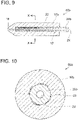
- the ceramic structure 50b is a variant of the ceramic structure 50, and comprises a ceramic shaft 20b and a ceramic tube 10b including through holes, which is different from the ceramic shaft 20 and the ceramic tube 10 of the ceramic structure 50.
- Elements of the ceramic structure 50b that are substantially the same as those of the ceramic structure 50 are denoted with the same reference signs as those used for the ceramic structure 50 and descriptions for these elements may be omitted.
- FIG. 9 corresponds to the cross section illustrated in FIG. 2 in connection with the ceramic structure 50
- FIG. 10 corresponds to the cross section illustrated in FIG. 5 in connection with the ceramic structure 50.
- the ceramic shaft 20b includes a first through hole 24 axially extending from one end to the other end. That is, the ceramic shaft 20b has a hollow structure. As illustrated in FIG. 10 , the first through hole 24 is open at both axial ends. The diameter of the first through hole 24 is adjusted to 200 to 3000 ⁇ m (may be 200 to 1000 ⁇ m). Further, the electrodes 22 are disposed on the outer circumferential surface of the ceramic shaft 20b at intervals circumferentially. The electrodes 22 are embedded in a ceramic resulting from the ceramic shaft 20b and the ceramic tube 10b being bonded and integrated.
- the ceramic tube 10b includes a second through hole 18 extending from the bottom (surface contacting the axial end surface of the ceramic shaft 20b) of the hole (housing portion) 12 to the outside of the ceramic tube 10b.
- the second through hole 18 communicates with the first through hole 24.
- the diameter of the second through hole 18 is adjusted to 20 to 1000 ⁇ m (may be 20 to 300 ⁇ m). That is, the diameter of the second through hole 18 may be smaller than the diameter of the first through hole 24.
- the ceramic structure 50b can be considered to include a through hole extending axially from its one end to the other end (the first through hole 24 and the second through hole 18).
- the ceramic structure 50b can be used as a heater for heating the matter. Further, the ceramic structure 50b can be used as a vacuum adsorption device that adsorbs another substance to the matter within the first through hole 24 by depressurizing the first through hole 24 though deaeration of gas in the first through hole 24 via the second through hole 18. In this case, it is possible to adsorb another substance to the matter while heating the matter within the first through hole 24 by turning on the heater. Typically, the higher the temperature of the matter becomes, the faster the adsorption rate becomes.
- the ceramic structure 50b can be used as a vacuum adsorption device with a heater.
- a configuration may be employed in which the ceramic shaft 20b includes the first through hole 24 and the ceramic tube 10b does not include the second through hole 18 (i.e., a configuration in which the ceramic tube 10 is used instead of the ceramic tube 10b).
- Such a configuration can also allow for placement of matter within the first through hole 24 and heating thereof.
- the diameters of the first through hole 24 and the second through hole 18 can be varied appropriately depending on the purpose, for example, the diameters of the first through hole 24 and the second through hole can be equal to each other.
Landscapes
- Chemical & Material Sciences (AREA)
- Engineering & Computer Science (AREA)
- Ceramic Engineering (AREA)
- Inorganic Chemistry (AREA)
- Resistance Heating (AREA)
Abstract
Description
- The present specification discloses a technique relating to an electrode-embedded ceramic structure.
-
Japanese Patent Application Publication No. 2011-207222 - As described, in Patent Document 1, the intermediate in which the ceramic sheet is pressure bonded to the ceramic shaft is fired. As a result, the ceramic sheet is bonded and integrated with the ceramic shaft, completing a structure in which the electrode is embedded in the ceramic. The ceramic heater of Patent Document 1 includes a structure in which a matrix (ceramic) has a different material (electrode) from the matrix embedded therein. Thus, the matrix may be degraded, such as the matrix being cracked, for example, due to a thermal expansion rate difference between the ceramic and the electrode. There is a need for improved durability (degradation control) of ceramic structures having an electrode embedded therein. The present specification aims to realize an electrode-embedded ceramic structure with improved durability.
- An electrode-embedded ceramic structure disclosed in the present specification may comprise a ceramic shaft, wherein an electrode is disposed on an outer circumference thereof; and a ceramic tube housing the ceramic shaft therein and coupled to the ceramic shaft. In this electrode-embedded ceramic structure, spaces may be provided locally between the ceramic shaft and the ceramic tube.
-
-
FIG. 1 illustrates a schematic view (perspective view) of an electrode-embedded ceramic structure according to a first embodiment; -
FIG. 2 illustrates a cross-sectional view along a line II-II inFIG. 1 ; -
FIG. 3 illustrates an enlarged view of an area enclosed by a broken line III inFIG. 2 ; -
FIG. 4 illustrates a cross-sectional view along a line IV-IV inFIG. 2 ; -
FIG. 5 illustrates a cross-sectional view along a line V-V inFIG. 2 : -
FIG. 6 illustrates an enlarged view of an area enclosed by a broken line VI inFIG. 5 ; -
FIG. 7 illustrates a manufacturing process of the electrode-embedded ceramic structure; -
FIG. 8 illustrates a variant of the electrode-embedded ceramic structure according to the first embodiment (in cross-sectional view); -
FIG. 9 illustrates a cross-sectional view of an electrode-embedded ceramic structure according to a second embodiment; and -
FIG. 10 illustrates a cross-sectional view along a line X-X inFIG. 9 . - An electrode-embedded ceramic structure disclosed in the present specification may comprise a ceramic shaft, wherein an electrode is disposed on an outer circumference thereof: and a ceramic tube housing the ceramic shaft therein and coupled to the ceramic shaft. The electrode-embedded ceramic structure disclosed in the present specification is manufactured by preparing the ceramic shaft that has the electrode (wiring pattern) provided on the outer circumference and the ceramic tube separately, inserting the ceramic shaft into the ceramic tube, and firing this assembly. By firing the assembly with the ceramic shaft inserted in the ceramic tube, the ceramic shaft and the ceramic tube are bonded and thus integrated. That is, the electrode is embedded in the ceramic. In the ceramic shaft before insertion into the ceramic tube, the electrode may not be exposed at a surface (outer circumferential surface) of the ceramic shaft. For example, in the ceramic shaft before insertion into the ceramic tube, a surface of the electrode may be covered by a protection layer or the like.
- In the electrode-embedded ceramic structure, spaces may be provided locally between the ceramic shaft and the ceramic tube. Here, "between the ceramic shaft and the ceramic tube" means an interface at which the outer surface of the ceramic shaft joins (contacts) an inner surface of the ceramic tube (inner wall of the tube) before they arc bonded. The interface between the ceramic shaft and the ceramic tube can be identified, even after they have been bonded and integrated, based on a distance from the center axis or outer surface of the electrode-embedded ceramic structure, observation of a cross-sectional image of the electrode-embedded ceramic structure, the position of the electrode in a cross-sectional image, or the like.
- A material of the ceramic shaft and the ceramic tube may be an alumina-containing material or a zirconia-containing material. Examples of the alumina-containing material include alumina (Al2O3), mullite (Al6O13Si2). spinel (MgAl3O4). etc. Examples of the zirconia-containing material include zirconia (ZrO2), zirconia-containing materials such as partially stabilized zirconia and stabilized zirconia to which yttria (Y2O3), calcia (CaO), etc. are added as stabilizers, etc. A homogeneous material may be used (e.g., the ceramic shaft and the ceramic tube are constituted of alumina) or different materials may be used (e.g., the ceramic shaft is constituted of alumina and the ceramic tube is constituted of zirconia). It is preferable that the ceramic shaft and the ceramic tube are constituted of a homogeneous material to bond them favorably.
- The ceramic shaft may have a solid cylinder shape or a hollow cylinder shape. That is, the ceramic shaft may be solid or hollow. In case of the ceramic shaft having a hollow cylinder shape, one end thereof may be closed (bottomed hollow cylinder), both ends thereof may be closed (hollow cylinder), or the both ends may be open. The ceramic shaft with its both ends open can be considered to include a through hole (first through hole) extending axially from one end to the other end. Providing the first through hole in the ceramic shaft allows matter (liquid such as water, a solid such as a metal wire) to be disposed within the ceramic shaft.
- The electrode may be disposed on the outer circumference of the ceramic shaft. Providing the ceramic shaft with the electrode allows the electrode-embedded ceramic structure to be used as a heater (ceramic heater). In case of the ceramic shaft including the first through hole, matter can be disposed within the first through hole and be heated therein. For example, platinum (Pt), Au-Pt alloy containing gold (Au), etc. may be used as a material of the electrode. The electrode may be formed on the outer circumferential surface of the ceramic shaft by screen printing, vapor deposition. or the like. Further, a surface of the electrode may be covered by a protection layer after the electrode has been formed on the outer circumferential surface of the ceramic shaft. Although a material of the protection layer is not particularly limited, resin, ceramic, etc. can be used.
- The ceramic tube may include a hole for housing the ceramic shaft (housing portion). Specifically, the ceramic tube may have a bottomed hollow cylinder shape including a bottom surface that contacts a longitudinal end surface of the ceramic shaft and an inner circumferential surface that contacts the outer circumferential surface of the ceramic shaft. Further, a through hole (second through hole) communicating with the outside of the ceramic tube may be defined in the bottom surface. In this case, the second through hole may communicate with the first through hole. That is, the ceramic tube may include the second through hole that extends from the housing portion in which the ceramic shaft is housed to the outside of the ceramic tube and communicates with the first through hole. In this case, the first through hole can be depressurized by suction of the first through hole via the second through hole.
- Depressurizing the first through hole via the second through hole while matter is disposed within the first through hole allows for adsorption of another material (such as metal) to the matter disposed within the first through hole. That is, the first through hole and the second through hole allow the electrode-embedded ceramic structure to be used as a vacuum adsorption device. Further, as described, providing the ceramic shaft with the electrode allows the electrode-embedded ceramic structure to be used as a heater. Thus, by including the first through hole and the second through hole, the electrode-embedded ceramic structure can adsorb another substance to matter, while heating the matter.
- In case of the electrode-embedded ceramic structure including the first through hole and the second through hole, the diameters of the first through hole and the second through hole may be the same or different. In case of the diameters of the first through hole and the second through hole being different, the diameter of the second through hole may be smaller than the diameter of the first through hole. As described, providing the ceramic shaft with the first through hole allows for placement of matter within the first through hole, heating thereof, and adsorption thereto. The diameter of the second through hole being smaller than the diameter of the first through hole reduces leakage of the matter disposed within the first through hole to the outside of the electrode-embedded ceramic structure. Further, in depressurizing (deaerating) the first through hole. a pressure decrease in the first through hole is further facilitated as the diameter of the second through hole is smaller. The outer shape of the ceramic tube may be any shape, and for example, may be a cylinder or polygonal prism.
- In the state where the ceramic shaft is inserted in the ceramic tube, the entirety of the longitudinal end surface of the ceramic shaft may be in contact with the ceramic tube or a part thereof may not be in contact therewith. Similarly, in the state where the ceramic shaft is inserted in the ceramic tube, the entirety of the outer circumferential surface of the ceramic shaft may be in contact with the inner circumferential surface of the ceramic tube or a part thereof may not be in contact therewith. Here, "the state where the ceramic shaft is inserted in the ceramic tube" means a state prior to firing of the ceramic shaft and the ceramic tube to bond them.
- For example. by providing the end surface of the ceramic shaft and/or the bottom surface of the ceramic tube with a recess, the end surface of the ceramic shaft can be partially non-contact with the bottom surface of the ceramic tube. Similarly, by providing the outer circumferential surface of the ceramic shaft and/or the inner circumferential surface of the ceramic tube with a recess, the outer circumferential surface of the ceramic shaft can be partially non-contact with the inner circumferential surface of the ceramic tube. By maintaining the ceramic shaft and the ceramic tube partially non-contact with each other in the state where the ceramic shaft is inserted in the ceramic tube, spaces are provided locally between the ceramic shaft and the ceramic tube.
- Further, a pore-forming material may be added to the ceramic shaft and/or the inside of the ceramic tube, and the pore-forming material may be eliminated upon firing the electrode-embedded ceramic structure (the ceramic shaft and the ceramic tube). This method can also provide spaces locally between the ceramic shaft and the ceramic tube. Polymer particles, carbon particles, etc. can be used as the pore-forming material. A space volume (space ratio) of the entire electrode-embedded ceramic structure and a space volume (space ratio) between the ceramic shaft and the ceramic tube can be controlled by adjusting the kind of pore-forming material (material, particle size) and an amount of the pore-forming material to be added.
- Further, spaces can also be provided between the ceramic shaft and the ceramic tube by controlling a firing condition for the electrode-embedded ceramic structure (firing temperature, firing time, etc.) as well. As described, the electrode-embedded ceramic structure disclosed in the present specification is manufactured by preparing the ceramic shaft and the ceramic tube separately, inserting the ceramic shaft into the ceramic tube, and then firing the assembly. Thus, before firing (in the state where the ceramic shaft is inserted in the ceramic tube), there is a distinct interface between the ceramic shaft and the ceramic tube. Then, during firing, bonding progresses at the interface between the ceramic shaft and the ceramic tube, and thus they are integrated. By controlling the firing condition, a degree of the bonding (progress of the bonding) between the ceramic shaft and the ceramic tube can be controlled and spaces can be provided at parts between the ceramic shaft and the ceramic tube.
- As described. in the electrode-embedded ceramic structure disclosed in the present specification, spaces are provided locally between the ceramic shaft and the ceramic tube. Thus, for example, when the electrode generates heat or when the electrode-embedded ceramic structure is heated, a force applied from the electrode to the ceramic can be mitigated by the spaces between the ceramic shaft and the ceramic tube. Specifically, it is possible to suppress cracks in the ceramic (the ceramic shaft and the ceramic tube) caused by a thermal expansion rate difference between the matrix (the ceramic) and the electrode. Providing spaces between the ceramic shaft and the ceramic tube allows for improved durability of the electrode-embedded ceramic structure.
- The space volume (space ratio) between (at the interface between) the ceramic shaft and the ceramic tube can be determined from an image of a cross section of the electrode-embedded ceramic structure (a cross section along a plane including the ceramic shaft or a cross section along a plane perpendicular to the ceramic shaft). Specifically, a SEM image of a cross section of the ceramic structure is firstly obtained to identify the interface between the ceramic shaft and the ceramic tube. Then, an area of the spaces per 1 µm of the interface length is measured. The area of the spaces can be calculated, for example, by image-processing the obtained SEM image by iTEM analysis software (manufactured by Seika Corporation). The area of the spaces per 1 µm of the interface length (space area/µm) may be 0.3 µm2 or more. With the space area of 0.3 µm2, the force applied from the electrode to the ceramic is sufficiently mitigated, and thus the electrode-embedded ceramic structure can have improved durability.
- The space area at the interface of the ceramic shaft and the ceramic tube may be 0.5 µm2 or more, 1 µm2 or more, 1.5 µm2 or more, or 2 µm2 or more. The force applied to the ceramic is further mitigated as the space area per 1 µm of the interface length is larger. Further, the space area at the interface between the ceramic shaft and the ceramic tube may be 5 µm2 or less. With the space area of 5 µm2 or less, the ceramic shaft and the ceramic tube are sufficiently joined (bonded) and thus separation of the ceramic shaft from the ceramic tube due to an impact can be prevented. The space area at the interface between the ceramic shaft and the ceramic tube may be 4.5 µm2 or less, 4 µm2 or less, 3.5 µm2 or less, or 3 µm2 or less.
- It is preferable that the spaces are uniformly distributed over the interface between the ceramic shaft and the ceramic tube. For example, when the interface between the end surface of the ceramic shaft and the ceramic tube is equally divided into four sections in an image of a cross section along a plane including the axis of the ceramic shaft, it is preferable that the spaces are observed in two or more sections of the four sections. It is more preferable that the spaces are observed in all of the four sections. Further, where the interface between a side surface (outer circumferential surface) of the ceramic shaft and the ceramic tube is equally divided into four sections (except for a portion where the electrode is disposed) in the same cross-sectional image, it is preferable that the spaces are observed in two or more sections, and it is more preferable that the spaces are observed in all of the four sections. Similarly, where the interface is equally divided into four sections (except for the portion where the electrode is disposed) in a cross section along a plane perpendicular to the axis of the ceramic shaft, it is preferable that the spaces are observed in two or more sections, and it is more preferable that the spaces are observed in all of the four sections.
- Referring to the drawings, a
ceramic structure 50 is described. Theceramic structure 50 is an example of the electrode-embedded ceramic structure. Theceramic structure 50 is used as a ceramic heater. As illustrated inFIGS. 1 and 2 , theceramic structure 50 comprises aceramic shaft 20 that has a solid cylinder shape and haselectrodes 22 disposed on an outer circumference (outer circumferential surface) thereof and aceramic tube 10 that has a bottomed hollow cylinder shape. The outer shape of theceramic tube 10 is substantially cylindrical, however, its end portion at an end has a substantially conical shape with its diameter decreasing toward the end. Theceramic shaft 20 is housed in theceramic tube 10. Theceramic shaft 20 and theceramic tube 10 are constituted of alumina, and are bonded and integrated with each other. Thus, theelectrodes 22 are embedded in the ceramic. -
FIG. 3 is a part of a cross section including the axis of the ceramic shaft 20 (longitudinal cross section) and an enlarged view of a broken-line area III inFIG. 2 . As illustrated inFIG. 3 ,spaces 40 are provided at intervals at an interface between theceramic shaft 20 and theceramic tube 10. Thespaces 40 are distributed almost uniformly over the interface between theceramic shaft 20 and theceramic tube 10. At portions where nospaces 40 are provided, theceramic shaft 20 and theceramic tube 10 are bonded. InFIG. 3 , thespaces 40 are depicted in relatively large size and in a schematic manner to assist in understanding features of theceramic structure 50. In actuality, the spaces do not have a specific shape and vary in size. -
FIG. 4 illustrates a cross section perpendicular to the axis of the ceramic shaft 20 (radial cross section) and illustrates a cross section along a line IV-IV inFIG. 2 . As apparent fromFIG. 4 , theceramic shaft 20 has a solid structure. As illustrated inFIG. 4 , in a circumferential direction of theceramic shaft 20 as well, thespaces 40 are provided at intervals and almost uniformly over the interface between theceramic shaft 20 and theceramic tube 10. In other words, bondedportions 42 where theceramic shaft 20 and theceramic tube 10 are bonded are provided at intervals and almost uniformly in the circumferential direction of theceramic shaft 20. This mitigates a circumferential local concentration of internal stress caused when theceramic structure 50 was fired (shrink fitted). InFIG. 4 as well, thespaces 40 are schematically depicted in relatively large size. -
FIG. 5 illustrates a cross section perpendicular to the axis of the ceramic shaft 20 (radial cross section) for portions where theelectrodes 22 are disposed and illustrates a cross section along a line V-V inFIG. 2 . InFIG. 5 , the spaces at the interface between theceramic shaft 20 and theceramic tube 10 are not illustrated to clearly show the state of theelectrodes 22. As illustrated inFIG. 5 , front and rear surfaces of theelectrodes 22 contact the ceramic (theceramic shaft 20 and the ceramic tube 10). That is. theelectrodes 22 are embedded in the ceramic configuring theceramic structure 50. In theceramic structure 50, theelectrodes 22 do not fully circumferentially extend, and there are portions between theelectrodes ceramic shaft 20 and theceramic tube 10 are bonded. -
FIG. 6 is an enlarged view of a border between a portion where anelectrode 22 is disposed and a portion where noelectrodes 22 are disposed (contact portion between theceramic shaft 20 and the ceramic tube 10) and illustrates an area enclosed by a broken line VI inFIG. 5 . As shown inFIG. 6 , no spaces are observed at an interface between theelectrode 22 and theceramic shaft 20 and at an interface between theelectrode 22 and theceramic tube 10. On the other hand, thespaces 40 are observed at intervals at the interface between theceramic shaft 20 and theceramic tube 10. - As illustrated in
FIGS. 3 to 6 , in theceramic structure 50, thespaces 40 are provided at intervals and almost uniformly over the interface between theceramic shaft 20 and theceramic tube 10. Thus, thespaces 40 can reduce a force applied to the ceramic due to a thermal expansion rate difference between theelectrodes 22 and the ceramic. On the other hand, no spaces are provided between theelectrodes 22 and the ceramic. This prevents heat transfer between theelectrodes 22 and the ceramic upon heat generation by theelectrodes 22 from being cut off, realizing a heater with high responsivity (the temperature of the ceramic changes responsively according to temperature change of the electrodes 22). - Referring to
FIG. 7 . a manufacturing method of theceramic structure 50 is described. For theceramic structure 50, firstly theceramic shaft 20 that is constituted of alumina and has the electrodes (Pt electrodes) 22 vapor deposited on its surface was prepared, theceramic tube 10 constituted of alumina in which a hole (bottomed hole) 12 is provided at the center was prepared separately from theceramic shaft 20, and theceramic shaft 20 was inserted into thehole 12. That is, thehole 12 is a housing portion for housing theceramic shaft 20. Theceramic shaft 20 was inserted until its end surface contacts the bottom of thehole 12. The diameter of thehole 12 is constant from its one end to the other end, and is substantially equal to the diameter of theceramic shaft 20. Thereafter, firing was performed at 1600°C in the atmosphere, resulting in theceramic structure 50. For theceramic structure 50, images of cross sections shown inFIGS. 3 to 5 were captured, and it was observed that spaces were provided almost uniformly over the interface between theceramic shaft 20 and theceramic tube 10. Further, as a result of measurement for an area of the spaces per 1 µm of an interface length over 100 µm of the interface, the area of the spaces was 0.3 µm2/µm. - A characteristic (durability) of the
ceramic structure 50 was evaluated. Specifically, a test (thermal shock test) was conducted where one cycle of the test incudes a process of: repeatedly changing a voltage applied to theelectrodes 22; increasing the temperature of theceramic structure 50 to 600°C in 10 seconds; and cooling it to 100°C in 20 seconds. As a comparative example, a ceramic structure was manufactured in a conventional manufacturing method, that is. by preparing a ceramic sheet that is constituted of alumina and has Pt electrodes printed on its surface. wrapping the ceramic sheet around a ceramic shaft constituted of alumina while pressing the ceramic shaft against the ceramic sheet, and then firing the assembly at 1600°C in the atmosphere. In the ceramic structure of the comparative example, the interface between the ceramic sheet and the ceramic shaft were entirely bonded and spaces were hardly observed at the interface. Specifically, the area of spaces was less than 0.01 µm2/µm. - As a result of the test above, the ceramic structure of the comparative example had cracks at the interface between the ceramic sheet and the ceramic shaft in 20th cycle. On the other hand, in the
ceramic structure 50, no cracks were observed at the interface between theceramic shaft 20 and theceramic tube 10 even after 100 cycles. It has been confirmed that in theceramic structure 50, thespaces 40 between theceramic shaft 20 and theceramic tube 10 mitigate thermal shock due to the thermal expansion rate difference between theelectrodes 22 and the ceramic (theceramic shaft 20 and the ceramic tube 10) and suppress degradation of the ceramic. - In the embodiment above, the
ceramic structure 50 is described as including theceramic tube 10 in which thehole 12, of which diameter is constant from its one end to the other end, is defined. However, such as aceramic structure 50a illustrated inFIG. 8 , aceramic tube 10a in which thehole 12 includes arecess 14 at abottom surface 12a and a plurality ofrecesses 16 at an innercircumferential surface 12b can be used. Therecesses 16 extend entirely on the inner circumferential surface of theceramic tube 10a. By providing therecess 14, a space is surely provided between theceramic shaft 20 and theceramic tube 10a at the end surface of theceramic shaft 20. Similarly, by providing therecesses 16, spaces are surely provided between theceramic shaft 20 and theceramic tube 10a at the outer circumferential surface of theceramic shaft 20. - As a variant of the
ceramic structure 50a, only therecess 14 may be provided and therecesses 16 may not be provided, or therecess 14 may not be provided and only therecesses 16 may be provided. Further, therecesses 16 may not entirely extend on the inner circumferential surface of theceramic tube 10a, for example, may be provided at intervals in the circumferential direction. Alternatively, therecesses 16 may be provided to face theceramic shaft 20 in portions where theelectrodes 22 are not provided. - Referring to
FIGS. 9 and 10 , aceramic structure 50b is described. Theceramic structure 50b is a variant of theceramic structure 50, and comprises aceramic shaft 20b and aceramic tube 10b including through holes, which is different from theceramic shaft 20 and theceramic tube 10 of theceramic structure 50. Elements of theceramic structure 50b that are substantially the same as those of theceramic structure 50 are denoted with the same reference signs as those used for theceramic structure 50 and descriptions for these elements may be omitted.FIG. 9 corresponds to the cross section illustrated inFIG. 2 in connection with theceramic structure 50, andFIG. 10 corresponds to the cross section illustrated inFIG. 5 in connection with theceramic structure 50. - As illustrated in
FIG. 9 , theceramic shaft 20b includes a first throughhole 24 axially extending from one end to the other end. That is, theceramic shaft 20b has a hollow structure. As illustrated inFIG. 10 , the first throughhole 24 is open at both axial ends. The diameter of the first throughhole 24 is adjusted to 200 to 3000 µm (may be 200 to 1000 µm). Further, theelectrodes 22 are disposed on the outer circumferential surface of theceramic shaft 20b at intervals circumferentially. Theelectrodes 22 are embedded in a ceramic resulting from theceramic shaft 20b and theceramic tube 10b being bonded and integrated. - The
ceramic tube 10b includes a second throughhole 18 extending from the bottom (surface contacting the axial end surface of theceramic shaft 20b) of the hole (housing portion) 12 to the outside of theceramic tube 10b. The second throughhole 18 communicates with the first throughhole 24. The diameter of the second throughhole 18 is adjusted to 20 to 1000 µm (may be 20 to 300 µm). That is, the diameter of the second throughhole 18 may be smaller than the diameter of the first throughhole 24. Theceramic structure 50b can be considered to include a through hole extending axially from its one end to the other end (the first throughhole 24 and the second through hole 18). - With matter (liquid, solid) disposed within the first through
hole 24, theceramic structure 50b can be used as a heater for heating the matter. Further, theceramic structure 50b can be used as a vacuum adsorption device that adsorbs another substance to the matter within the first throughhole 24 by depressurizing the first throughhole 24 though deaeration of gas in the first throughhole 24 via the second throughhole 18. In this case, it is possible to adsorb another substance to the matter while heating the matter within the first throughhole 24 by turning on the heater. Typically, the higher the temperature of the matter becomes, the faster the adsorption rate becomes. Theceramic structure 50b can be used as a vacuum adsorption device with a heater. - As a variant of the
ceramic structure 50b, a configuration may be employed in which theceramic shaft 20b includes the first throughhole 24 and theceramic tube 10b does not include the second through hole 18 (i.e., a configuration in which theceramic tube 10 is used instead of theceramic tube 10b). Such a configuration can also allow for placement of matter within the first throughhole 24 and heating thereof. The diameters of the first throughhole 24 and the second throughhole 18 can be varied appropriately depending on the purpose, for example, the diameters of the first throughhole 24 and the second through hole can be equal to each other. - While specific examples of the present disclosure have been described above in detail, these examples are merely illustrative and place no limitation on the scope of the patent claims. The technology described in the patent claims also encompasses various changes and modifications to the specific examples described above. The technical elements explained in the present description or drawings provide technical utility either independently or through various combinations. The present disclosure is not limited to the combinations described at the time the claims are filed. Further, the purpose of the examples illustrated by the present description or drawings is to satisfy multiple objectives simultaneously, and satisfying any one of those objectives gives technical utility to the present disclosure.
Claims (9)
- An electrode-embedded ceramic structure comprising:a ceramic shaft, wherein an electrode is disposed on an outer circumference thereof; anda ceramic tube housing the ceramic shaft therein and coupled to the ceramic shaft,whereinspaces are provided locally between the ceramic shaft and the ceramic tube.
- The electrode-embedded ceramic structure according to claim 1. wherein the spaces are each 0.3 µm2 or more per 1 µm of an interface length between the ceramic shaft and the ceramic tube.
- The electrode-embedded ceramic structure according to claim 1 or 2, wherein the spaces are provided at intervals in a circumferential direction of the ceramic shaft.
- The electrode-embedded ceramic structure according to any one of claims 1 to 3, wherein the ceramic shaft includes a first through hole axially extending from one end to another end.
- The electrode-embedded ceramic structure according to claim 4, wherein the ceramic tube includes a second through hole that extends from a housing portion in which the ceramic shaft is housed to outside of the ceramic tube and communicates with the first through hole.
- The electrode-embedded ceramic structure according to claim 5, wherein a diameter of the second through hole is smaller than a diameter of the first through hole.
- The electrode-embedded ceramic structure according to any one of claims 1 to 6, wherein a material of the ceramic shaft and ceramic tube is an alumina-containing material or zirconia-containing material.
- The electrode-embedded ceramic structure according to claim 7, wherein the ceramic shaft and the ceramic tube are constituted of a homogeneous material.
- The electrode-embedded ceramic structure according to any one of claims 1 to 8. wherein the electrode-embedded ceramic structure is a heater.
Applications Claiming Priority (2)
| Application Number | Priority Date | Filing Date | Title |
|---|---|---|---|
| JP2019188095 | 2019-10-11 | ||
| PCT/JP2020/037656 WO2021070763A1 (en) | 2019-10-11 | 2020-10-02 | Electrode-embedded ceramic structure |
Publications (2)
| Publication Number | Publication Date |
|---|---|
| EP4044765A1 true EP4044765A1 (en) | 2022-08-17 |
| EP4044765A4 EP4044765A4 (en) | 2023-11-01 |
Family
ID=75437937
Family Applications (1)
| Application Number | Title | Priority Date | Filing Date |
|---|---|---|---|
| EP20874607.3A Pending EP4044765A4 (en) | 2019-10-11 | 2020-10-02 | Electrode-embedded ceramic structure |
Country Status (4)
| Country | Link |
|---|---|
| US (1) | US12563645B2 (en) |
| EP (1) | EP4044765A4 (en) |
| JP (1) | JP7361128B2 (en) |
| WO (1) | WO2021070763A1 (en) |
Families Citing this family (2)
| Publication number | Priority date | Publication date | Assignee | Title |
|---|---|---|---|---|
| US20240225108A1 (en) * | 2022-05-30 | 2024-07-11 | Shenzhen Huachengda Precision Industry Co. Ltd. | Atomizer and atomizing assembly |
| WO2025203441A1 (en) * | 2024-03-28 | 2025-10-02 | 日本碍子株式会社 | Electrode-embedded ceramic structure |
Family Cites Families (9)
| Publication number | Priority date | Publication date | Assignee | Title |
|---|---|---|---|---|
| US7420139B2 (en) * | 2004-02-19 | 2008-09-02 | Ngk Spark Plug Co., Ltd. | Glow plug |
| GB2442890B (en) * | 2004-06-25 | 2008-08-27 | Kyocera Corp | Ceramic heater, method for manufacturing the same, heating apparatus and hair iron |
| GB2443361B (en) * | 2004-07-28 | 2008-07-30 | Kyocera Corp | Ceramic heater and heating iron using the same |
| JPWO2006011520A1 (en) * | 2004-07-28 | 2008-05-01 | 京セラ株式会社 | Ceramic heater and heating iron using the same |
| JP2006120559A (en) * | 2004-10-25 | 2006-05-11 | Ngk Spark Plug Co Ltd | Ceramic heater, heat exchange unit, and method of manufacturing ceramic heater |
| JP2006228713A (en) * | 2005-01-20 | 2006-08-31 | Ngk Spark Plug Co Ltd | Ceramic heater, heat exchange unit, warm water cleaning toilet seat, and method for manufacturing ceramic heater |
| JP2006222008A (en) * | 2005-02-14 | 2006-08-24 | Kyocera Corp | Ceramic heater and electronic components with built-in heater |
| JP5370396B2 (en) * | 2010-03-12 | 2013-12-18 | Tdk株式会社 | Manufacturing method of ceramic electronic component |
| JP6100642B2 (en) * | 2013-07-29 | 2017-03-22 | 京セラ株式会社 | heater |
-
2020
- 2020-10-02 JP JP2021551628A patent/JP7361128B2/en active Active
- 2020-10-02 WO PCT/JP2020/037656 patent/WO2021070763A1/en not_active Ceased
- 2020-10-02 EP EP20874607.3A patent/EP4044765A4/en active Pending
-
2022
- 2022-04-04 US US17/657,766 patent/US12563645B2/en active Active
Also Published As
| Publication number | Publication date |
|---|---|
| JPWO2021070763A1 (en) | 2021-04-15 |
| US12563645B2 (en) | 2026-02-24 |
| US20220232672A1 (en) | 2022-07-21 |
| WO2021070763A1 (en) | 2021-04-15 |
| JP7361128B2 (en) | 2023-10-13 |
| EP4044765A4 (en) | 2023-11-01 |
Similar Documents
| Publication | Publication Date | Title |
|---|---|---|
| US12563645B2 (en) | Electrode-embedded ceramic structure | |
| JP7089990B2 (en) | Sensor element | |
| US20130031952A1 (en) | Gas sensor with thermal shock protection | |
| JP7402297B2 (en) | sensor element | |
| JP7122248B2 (en) | sensor element | |
| JP6934310B2 (en) | Sensor element | |
| US9696274B2 (en) | Gas sensor element and gas sensor | |
| JP2013234896A (en) | Gas sensor element and gas sensor | |
| US8080143B2 (en) | Gas sensor element, method for manufacturing the same, and gas sensor | |
| US20210389271A1 (en) | Sensor element of gas sensor | |
| WO2020071246A1 (en) | Sensor element | |
| US20210389270A1 (en) | Sensor element of gas sensor | |
| JP7261640B2 (en) | Sensor element of gas sensor | |
| US12135307B2 (en) | Sensor element of gas sensor | |
| JP5097082B2 (en) | Gas sensor and manufacturing method thereof | |
| US20090050480A1 (en) | Exhaust gas sensor | |
| JP4644109B2 (en) | Gas sensor | |
| WO2025203441A1 (en) | Electrode-embedded ceramic structure | |
| JP7543188B2 (en) | Sensor element | |
| JP4565563B2 (en) | Method for manufacturing gas sensor element | |
| JP4618681B2 (en) | Gas sensor element and gas sensor | |
| JP2010185891A (en) | Method of manufacturing gas sensor element, and method of manufacturing the gas sensor | |
| JP2021139830A (en) | Gas sensor | |
| JP2005049115A (en) | Oxygen sensor | |
| US20010042685A1 (en) | Gas sensor with an oxygen ion-conducting solid electrolyte |
Legal Events
| Date | Code | Title | Description |
|---|---|---|---|
| STAA | Information on the status of an ep patent application or granted ep patent |
Free format text: STATUS: THE INTERNATIONAL PUBLICATION HAS BEEN MADE |
|
| PUAI | Public reference made under article 153(3) epc to a published international application that has entered the european phase |
Free format text: ORIGINAL CODE: 0009012 |
|
| STAA | Information on the status of an ep patent application or granted ep patent |
Free format text: STATUS: REQUEST FOR EXAMINATION WAS MADE |
|
| 17P | Request for examination filed |
Effective date: 20220505 |
|
| AK | Designated contracting states |
Kind code of ref document: A1 Designated state(s): AL AT BE BG CH CY CZ DE DK EE ES FI FR GB GR HR HU IE IS IT LI LT LU LV MC MK MT NL NO PL PT RO RS SE SI SK SM TR |
|
| DAV | Request for validation of the european patent (deleted) | ||
| DAX | Request for extension of the european patent (deleted) | ||
| REG | Reference to a national code |
Ref country code: DE Ref legal event code: R079 Free format text: PREVIOUS MAIN CLASS: H05B0003180000 Ipc: H05B0003480000 |
|
| A4 | Supplementary search report drawn up and despatched |
Effective date: 20231002 |
|
| RIC1 | Information provided on ipc code assigned before grant |
Ipc: H05B 3/14 20060101ALI20230926BHEP Ipc: H05B 3/03 20060101ALI20230926BHEP Ipc: H05B 3/18 20060101ALI20230926BHEP Ipc: H05B 3/48 20060101AFI20230926BHEP |