EP4044416A1 - Dual sourced common 3-level vscf - Google Patents
Dual sourced common 3-level vscf Download PDFInfo
- Publication number
- EP4044416A1 EP4044416A1 EP22156066.7A EP22156066A EP4044416A1 EP 4044416 A1 EP4044416 A1 EP 4044416A1 EP 22156066 A EP22156066 A EP 22156066A EP 4044416 A1 EP4044416 A1 EP 4044416A1
- Authority
- EP
- European Patent Office
- Prior art keywords
- phase
- power
- lead
- positive
- negative
- Prior art date
- Legal status (The legal status is an assumption and is not a legal conclusion. Google has not performed a legal analysis and makes no representation as to the accuracy of the status listed.)
- Pending
Links
Images



Classifications
-
- H—ELECTRICITY
- H02—GENERATION; CONVERSION OR DISTRIBUTION OF ELECTRIC POWER
- H02M—APPARATUS FOR CONVERSION BETWEEN AC AND AC, BETWEEN AC AND DC, OR BETWEEN DC AND DC, AND FOR USE WITH MAINS OR SIMILAR POWER SUPPLY SYSTEMS; CONVERSION OF DC OR AC INPUT POWER INTO SURGE OUTPUT POWER; CONTROL OR REGULATION THEREOF
- H02M5/00—Conversion of AC power input into AC power output, e.g. for change of voltage, for change of frequency, for change of number of phases
- H02M5/40—Conversion of AC power input into AC power output, e.g. for change of voltage, for change of frequency, for change of number of phases with intermediate conversion into DC
- H02M5/42—Conversion of AC power input into AC power output, e.g. for change of voltage, for change of frequency, for change of number of phases with intermediate conversion into DC by static converters
- H02M5/44—Conversion of AC power input into AC power output, e.g. for change of voltage, for change of frequency, for change of number of phases with intermediate conversion into DC by static converters using discharge tubes or semiconductor devices to convert the intermediate DC into AC
- H02M5/453—Conversion of AC power input into AC power output, e.g. for change of voltage, for change of frequency, for change of number of phases with intermediate conversion into DC by static converters using discharge tubes or semiconductor devices to convert the intermediate DC into AC using devices of a triode or transistor type requiring continuous application of a control signal
- H02M5/458—Conversion of AC power input into AC power output, e.g. for change of voltage, for change of frequency, for change of number of phases with intermediate conversion into DC by static converters using discharge tubes or semiconductor devices to convert the intermediate DC into AC using devices of a triode or transistor type requiring continuous application of a control signal using semiconductor devices only
-
- H—ELECTRICITY
- H02—GENERATION; CONVERSION OR DISTRIBUTION OF ELECTRIC POWER
- H02M—APPARATUS FOR CONVERSION BETWEEN AC AND AC, BETWEEN AC AND DC, OR BETWEEN DC AND DC, AND FOR USE WITH MAINS OR SIMILAR POWER SUPPLY SYSTEMS; CONVERSION OF DC OR AC INPUT POWER INTO SURGE OUTPUT POWER; CONTROL OR REGULATION THEREOF
- H02M1/00—Details of apparatus for conversion
- H02M1/0067—Converter structures employing plural converter units, other than for parallel operation of the units on a single load
-
- H—ELECTRICITY
- H02—GENERATION; CONVERSION OR DISTRIBUTION OF ELECTRIC POWER
- H02M—APPARATUS FOR CONVERSION BETWEEN AC AND AC, BETWEEN AC AND DC, OR BETWEEN DC AND DC, AND FOR USE WITH MAINS OR SIMILAR POWER SUPPLY SYSTEMS; CONVERSION OF DC OR AC INPUT POWER INTO SURGE OUTPUT POWER; CONTROL OR REGULATION THEREOF
- H02M1/00—Details of apparatus for conversion
- H02M1/08—Circuits specially adapted for the generation of control voltages for semiconductor devices incorporated in static converters
-
- H—ELECTRICITY
- H02—GENERATION; CONVERSION OR DISTRIBUTION OF ELECTRIC POWER
- H02M—APPARATUS FOR CONVERSION BETWEEN AC AND AC, BETWEEN AC AND DC, OR BETWEEN DC AND DC, AND FOR USE WITH MAINS OR SIMILAR POWER SUPPLY SYSTEMS; CONVERSION OF DC OR AC INPUT POWER INTO SURGE OUTPUT POWER; CONTROL OR REGULATION THEREOF
- H02M7/00—Conversion of AC power input into DC power output; Conversion of DC power input into AC power output
- H02M7/02—Conversion of AC power input into DC power output without possibility of reversal
- H02M7/04—Conversion of AC power input into DC power output without possibility of reversal by static converters
- H02M7/06—Conversion of AC power input into DC power output without possibility of reversal by static converters using discharge tubes without control electrode or semiconductor devices without control electrode
- H02M7/10—Conversion of AC power input into DC power output without possibility of reversal by static converters using discharge tubes without control electrode or semiconductor devices without control electrode arranged for operation in series, e.g. for multiplication of voltage
-
- H—ELECTRICITY
- H02—GENERATION; CONVERSION OR DISTRIBUTION OF ELECTRIC POWER
- H02M—APPARATUS FOR CONVERSION BETWEEN AC AND AC, BETWEEN AC AND DC, OR BETWEEN DC AND DC, AND FOR USE WITH MAINS OR SIMILAR POWER SUPPLY SYSTEMS; CONVERSION OF DC OR AC INPUT POWER INTO SURGE OUTPUT POWER; CONTROL OR REGULATION THEREOF
- H02M7/00—Conversion of AC power input into DC power output; Conversion of DC power input into AC power output
- H02M7/42—Conversion of DC power input into AC power output without possibility of reversal
- H02M7/44—Conversion of DC power input into AC power output without possibility of reversal by static converters
- H02M7/48—Conversion of DC power input into AC power output without possibility of reversal by static converters using discharge tubes with control electrode or semiconductor devices with control electrode
- H02M7/483—Converters with outputs that each can have more than two voltages levels
- H02M7/487—Neutral point clamped inverters
-
- H—ELECTRICITY
- H02—GENERATION; CONVERSION OR DISTRIBUTION OF ELECTRIC POWER
- H02M—APPARATUS FOR CONVERSION BETWEEN AC AND AC, BETWEEN AC AND DC, OR BETWEEN DC AND DC, AND FOR USE WITH MAINS OR SIMILAR POWER SUPPLY SYSTEMS; CONVERSION OF DC OR AC INPUT POWER INTO SURGE OUTPUT POWER; CONTROL OR REGULATION THEREOF
- H02M1/00—Details of apparatus for conversion
- H02M1/0048—Circuits or arrangements for reducing losses
- H02M1/0054—Transistor switching losses
-
- H—ELECTRICITY
- H02—GENERATION; CONVERSION OR DISTRIBUTION OF ELECTRIC POWER
- H02M—APPARATUS FOR CONVERSION BETWEEN AC AND AC, BETWEEN AC AND DC, OR BETWEEN DC AND DC, AND FOR USE WITH MAINS OR SIMILAR POWER SUPPLY SYSTEMS; CONVERSION OF DC OR AC INPUT POWER INTO SURGE OUTPUT POWER; CONTROL OR REGULATION THEREOF
- H02M7/00—Conversion of AC power input into DC power output; Conversion of DC power input into AC power output
- H02M7/02—Conversion of AC power input into DC power output without possibility of reversal
- H02M7/04—Conversion of AC power input into DC power output without possibility of reversal by static converters
- H02M7/12—Conversion of AC power input into DC power output without possibility of reversal by static converters using discharge tubes with control electrode or semiconductor devices with control electrode
- H02M7/21—Conversion of AC power input into DC power output without possibility of reversal by static converters using discharge tubes with control electrode or semiconductor devices with control electrode using devices of a triode or transistor type requiring continuous application of a control signal
- H02M7/217—Conversion of AC power input into DC power output without possibility of reversal by static converters using discharge tubes with control electrode or semiconductor devices with control electrode using devices of a triode or transistor type requiring continuous application of a control signal using semiconductor devices only
- H02M7/25—Conversion of AC power input into DC power output without possibility of reversal by static converters using discharge tubes with control electrode or semiconductor devices with control electrode using devices of a triode or transistor type requiring continuous application of a control signal using semiconductor devices only arranged for operation in series, e.g. for multiplication of voltage
Definitions
- the present disclosure relates to power generation systems, and more particularly to aircraft generators.
- 4-phase, 3-level inverters help mitigate above weight/efficiency/power quality issues but still lack ability to compensate for voltage losses. Further, 4-phase, 3-level inverters also require balanced split DC link voltage. Typically, this is addressed by additional mid-point balancing closed-loop control techniques which results in additional switching losses and dynamic performance degradation under certain operating conditions.
- a system comprises a first 3-phase rectifier having a positive DC lead and a negative DC lead and a second 3-phase rectifier having a positive DC lead and a negative DC lead.
- the system also includes a 4-phase, 3-level inverter connected to the first and second 3-phase rectifiers.
- the positive DC lead of the first 3-phase rectifier can be connected to a positive input terminal of the 4-phase, 3-level inverter and the negative DC lead of the first 3-phase rectifier can be connected to a midpoint input terminal of the 4-phase, 3-level inverter.
- the positive DC lead of the second 3-phase rectifier can be connected to the midpont input terminal of the 4-phase, 3-level inverter and the negative DC lead of the second 3-phase rectifier can be connected to a negative input terminal of the 4-phase, 3-level inverter.
- the 4-phase, 3-level inverter can include a respective output for each of four AC phases including a neutral AC phase.
- the system can also include a first generator with three phases connected to the first 3-phase rectifier, and second generator with three phases connected to the second 3-phase rectifier.
- the first and second generators can be variable frequency generators.
- the first and second generators can be connected to a common output shaft of a prime mover or the first and second generators may be connected to a respective output shaft of a respective prime mover.
- Each of the three phases of the first and second rectifiers can be configured as a 115 V input phase and each of the first and second 3-phase rectifiers is configured for 270 V output to the 4-phase, 3-level inverter.
- the 4-phase, 3-level inverter can be configured to output 115 V, 400 Hz AC power from the four AC phases.
- Each of the first and second 3-phase rectifiers can include a respective capacitor connected across the respective positive and negative DC leads.
- the system can also include at least one GCU (generator control unit) operatively connected to control the first and second generators using feedback measured across the respective capacitors.
- GCU generator control unit
- the 4-phase, 3-level inverter can include a first input capacitor connected in series with a second input capacitor, where the first input capacitor can connect between the positive and midpoint input terminals of the 4-phase, 3-level inverter, and the second capacitor can connect between the midpoint and negative input terminals of the 4-phase, 3-level inverter.
- the 4-phase, 3-level inverter can also include four sets of switches, and each set of switches can be connected across the positive, negative, and midpoint input terminals, each of the set of switches being connected to a respective one of the AC phases.
- the system can include logic operatively connected to the switches to condition DC power from the first and second 3-phase rectifiers into AC power output to the AC phases. Each set of switches can be connected to a respective one of the AC phases through a network of inductors and capacitors.
- Another system includes a first 3-phase rectifier having a positive DC lead and a negative DC lead and a second 3-phase rectifier having a positive DC lead and a negative DC lead.
- the positive DC lead of the first 3-phase rectifier can be connected to a positive output terminal
- the negative DC lead of the first 3-phase rectifier can be connected to a midpoint output terminal
- the positive DC lead of the second 3-phase rectifier can be connected to the midpoint output terminal.
- the negative DC lead of the second 3-phase rectifier can be connected to a negative output terminal.
- a method comprises receiving variable frequency, 3-phase power from a first generator, receiving variable frequency, 3-phase power from a second generator, rectifying the variable frequency, 3-phase power from each of the first and second generators into DC power. And inverting the DC power into 4-phase, constant frequency power for powering a load.
- Inverting DC power into 4-phase, constant frequency power can include receiving the DC power as three level DC power. Receiving power from each of the first and second generators can further include receiving the power from the generators operating at the same speed. Inverting the DC power into 4-phase, constant frequency power can further include outputting neutral phase in the 4-phase constant frequency power.
- Fig. 1 a partial view of an embodiment of a system in accordance with the disclosure is shown in Fig. 1 and is designated generally by reference character 100.
- Other embodiments of systems in accordance with the disclosure, or aspects thereof, are provided in Figs. 2-3 , as will be described.
- the systems and methods described herein can be used to provide sufficient voltage headroom for a 3-level inverter, without the need for step-up transformers.
- a system 100 comprises a first 3-phase rectifier 102 (hereinafter referred to as “first rectifier 102”) having a positive DC lead and a negative DC lead and a second 3-phase rectifier (hereinafter referred to as “second rectifier 104") 104 having a positive DC lead and a negative DC lead.
- first rectifier 102 having a positive DC lead and a negative DC lead
- second rectifier 104 having a positive DC lead and a negative DC lead.
- a 4-phase, 3-level inverter 106 (hereinafter referred to as “inverter 106") can be connected to the first and second rectifiers 102,104 through respective leads.
- the positive DC lead of the first rectifier 102 can be connected to a positive input terminal 108 of the inverter 106 and the negative DC lead can be connected to a midpoint input terminal 110 of the inverter 106.
- the positive DC lead of the second rectifier 104 can be connected to the midpoint input terminal 110 of the inverter 106 and the negative DC can be connected to a negative input terminal 112 of the inverter 106.
- the inverter 106 can include a respective output for each of three AC phases A,B,C, and a respective output for a neutral AC phase N.
- the system 100 can also include a first generator 114 with three phases A,B,C connected to the first rectifier 102, and second generator 116 with three phases A,B,C connected to the second rectifier 104.
- the first and second generators 114,116 can be variable frequency generators, for example. Shown schematically in Figs. 1-2 , the first and second generators 114,116, can also be connected to a common output shaft 118 of a prime mover, or the generators 114,116 can be connected to separate prime movers (prime mover(s) not shown).
- Each of the three input phases A,B,C of the first and second rectifiers 102,104 can be configured as a 115 V phase, and each of the first and second rectifiers 102,104 can be configured for 270 V output to the inverter 106.
- the inverter 106 can be configured to output 115 V, 400 Hz AC power from the four AC phases A,B,C,N.
- Each of the first and second rectifiers 102,104 can include a respective capacitor 120,122 connected across the respective positive and negative DC leads.
- the system 100 can also include at least one generator control unit 124,126 operatively connected to control the first and second generators 114,116 using feedback measured across the respective capacitors 120,122.
- the inverter 106 can include a first input capacitor 128 connected in series with a second input capacitor 130.
- the first input capacitor 128 can connect between the positive and midpoint input terminals 108,110 of the inverter 106
- the second capacitor 130 can connect between the midpoint and negative input terminals 110, 112.
- the inverter 106 can also include four sets of switches and diodes 132,134,136,138 where each of these sets can be configured in a 3-level inverter phase leg.
- Each set of switches and diodes 132,134,136,138 can be connected across the positive, negative, and midpoint input terminals 108, 112, and 110 respectively, and each of the set of switches 132,134,136,138 can be connected to a respective one of the AC phases A,B,C,N.
- the system 100 can also include logic 140 operatively connected to the switches 132,134,136,138 to condition DC power from the first and second rectifiers 102,104 into AC power output to the AC phases A,B,C,N.
- Each set of switches 132,134,136,138 can also be connected to a respective one of the AC phases A,B,C,N through a network of inductors and capacitors 142.
- a system 300 can include a first rectifier 302 having a positive and a second rectifier 304.
- a positive DC lead of the first rectifier 302 can be connected to a positive output terminal 308 (e.g. for +270 V DC aircraft power) and a negative DC lead of the first rectifier 302 can be connected to a midpoint output terminal 310 (e.g. for ⁇ 270 V DC aircraft power).
- a positive DC lead of the second rectifier 304 can be connected to the midpoint output terminal 310 and a negative DC lead of the second rectifier 304 can be connected to a negative output terminal 312 (e.g. for -270 V DC aircraft power).
- a generator 314 may be connected to the first rectifier 302 and a second generator 316 may be connected to the second rectifier 304.
- the system 300 may be similar to that of system 100 described above, in that generators 314,316 may be variable frequency generators, may output the three AC phases A,B,C, and may be connected to a common shaft of a prime mover, or the generators 314,316 may be connected to separate prime movers. Additionally, the system 300 can also include at least one generator control unit 324,326 operatively connected to control the first and second generators 314,616 using feedback measured across the respective capacitors 320,322.
- a method 200 can comprise, at boxes 202 and 204, receiving variable frequency, 3-phase power from a first generator 114 and receiving variable frequency, 3-phase power from a second generator 116.
- the method 200 can include rectifying the variable frequency, 3-phase power from each of the first and second generators 114,116 into DC power.
- the method 200 can include inverting the DC power into 4-phase, constant frequency power for powering a load, for example using inverter 106 as described above.
- Inverting DC power into 4-phase, constant frequency power can include, at box 210, receiving the DC power as three level switched DC power. Shown at box 212, receiving power from each of the first and second generators 114,116 can further include receiving the power from the generators 114,116 operating at the same speed, e.g. because generators 114,116 can be on the same shaft 118 of a prime mover or different prime movers. Further, at box 214, inverting the DC power into 4-phase, constant frequency power can further include outputting neutral phase N in the 4-phase constant frequency power.
- a total DC link of 540 Vdc provides sufficient voltage headroom for the inverter to adequately produce a high quality 115Vac VSCF output across all operating loads and/or conditions, such as linear, non-linear, and motor-driven aircraft accessories (e.g. pumps, compressors, fans), without the need for step-up transformer.
- linear, non-linear, and motor-driven aircraft accessories e.g. pumps, compressors, fans
Landscapes
- Engineering & Computer Science (AREA)
- Power Engineering (AREA)
- Inverter Devices (AREA)
Abstract
Description
- The present disclosure relates to power generation systems, and more particularly to aircraft generators.
- Power conversion for aircraft generators and onboard loads is a specialty with increasing demands upon it as the trend toward more-electric aircraft progresses. Conventional DC-link based 3-phase, 2-level inverter VSCF (variable speed constant frequency) electric power generation requires neutral-forming transformer (NFT) which are heavy and can be inefficient. Hence, not desirable for aerospace applications especially for high power (e.g., >50 kW), and unpressurized environments.
- Further, if nominal output voltage of the input engine-driven generators are about same as required VSCF output voltage then typically the NFT would be required to provide additional attribute of stepping up the voltage to account for various voltage losses in the conversion system. 4-phase, 2-level inverter implementation helps eliminate NFT but still lacks ability to step-up the voltage, and also suffers from heavy power quality / EMC (electromagnetic compatibility) filters and lower efficiency.
- 4-phase, 3-level inverters help mitigate above weight/efficiency/power quality issues but still lack ability to compensate for voltage losses. Further, 4-phase, 3-level inverters also require balanced split DC link voltage. Typically, this is addressed by additional mid-point balancing closed-loop control techniques which results in additional switching losses and dynamic performance degradation under certain operating conditions.
- The conventional techniques have been considered satisfactory for their intended purpose. However, there is an ever present need for improved systems and methods for light weight, high efficiency power generation. This disclosure provides a solution for this need.
- A system comprises a first 3-phase rectifier having a positive DC lead and a negative DC lead and a second 3-phase rectifier having a positive DC lead and a negative DC lead. The system also includes a 4-phase, 3-level inverter connected to the first and second 3-phase rectifiers.
- The positive DC lead of the first 3-phase rectifier can be connected to a positive input terminal of the 4-phase, 3-level inverter and the negative DC lead of the first 3-phase rectifier can be connected to a midpoint input terminal of the 4-phase, 3-level inverter. The positive DC lead of the second 3-phase rectifier can be connected to the midpont input terminal of the 4-phase, 3-level inverter and the negative DC lead of the second 3-phase rectifier can be connected to a negative input terminal of the 4-phase, 3-level inverter. The 4-phase, 3-level inverter can include a respective output for each of four AC phases including a neutral AC phase.
- The system can also include a first generator with three phases connected to the first 3-phase rectifier, and second generator with three phases connected to the second 3-phase rectifier. The first and second generators can be variable frequency generators. The first and second generators can be connected to a common output shaft of a prime mover or the first and second generators may be connected to a respective output shaft of a respective prime mover.
- Each of the three phases of the first and second rectifiers can be configured as a 115 V input phase and each of the first and second 3-phase rectifiers is configured for 270 V output to the 4-phase, 3-level inverter. The 4-phase, 3-level inverter can be configured to output 115 V, 400 Hz AC power from the four AC phases. Each of the first and second 3-phase rectifiers can include a respective capacitor connected across the respective positive and negative DC leads. The system can also include at least one GCU (generator control unit) operatively connected to control the first and second generators using feedback measured across the respective capacitors.
- The 4-phase, 3-level inverter can include a first input capacitor connected in series with a second input capacitor, where the first input capacitor can connect between the positive and midpoint input terminals of the 4-phase, 3-level inverter, and the second capacitor can connect between the midpoint and negative input terminals of the 4-phase, 3-level inverter. The 4-phase, 3-level inverter can also include four sets of switches, and each set of switches can be connected across the positive, negative, and midpoint input terminals, each of the set of switches being connected to a respective one of the AC phases. The system can include logic operatively connected to the switches to condition DC power from the first and second 3-phase rectifiers into AC power output to the AC phases. Each set of switches can be connected to a respective one of the AC phases through a network of inductors and capacitors.
- Another system includes a first 3-phase rectifier having a positive DC lead and a negative DC lead and a second 3-phase rectifier having a positive DC lead and a negative DC lead. The positive DC lead of the first 3-phase rectifier can be connected to a positive output terminal, the negative DC lead of the first 3-phase rectifier can be connected to a midpoint output terminal, and the positive DC lead of the second 3-phase rectifier can be connected to the midpoint output terminal. The negative DC lead of the second 3-phase rectifier can be connected to a negative output terminal.
- A method comprises receiving variable frequency, 3-phase power from a first generator, receiving variable frequency, 3-phase power from a second generator, rectifying the variable frequency, 3-phase power from each of the first and second generators into DC power. And inverting the DC power into 4-phase, constant frequency power for powering a load.
- Inverting DC power into 4-phase, constant frequency power can include receiving the DC power as three level DC power. Receiving power from each of the first and second generators can further include receiving the power from the generators operating at the same speed. Inverting the DC power into 4-phase, constant frequency power can further include outputting neutral phase in the 4-phase constant frequency power.
- These and other features of the systems and methods of the subject disclosure will become more readily apparent to those skilled in the art from the following detailed description taken in conjunction with the drawings.
- So that those skilled in the art to which the subject disclosure appertains will readily understand how to make and use the devices and methods of the subject disclosure without undue experimentation, embodiments thereof will be described in detail herein below with reference to certain figures, wherein:
-
Fig. 1 is a schematic of an embodiment of a system constructed in accordance with the present disclosure, showing the connection between generators, rectifiers, and inverters; -
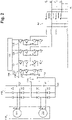
Fig. 2 is a detailed schematic circuit diagram of the system ofFig. 1 showing the switches in the 4-phase, 3-level inverter; and -
Fig. 3 is a schematic of an embodiment of a system constructed in accordance with the present disclosure, showing the connection between generators and rectifiers; -
Fig. 4 is a schematic block diagram showing a method in accordance with at least one aspect of this disclosure. - Reference will now be made to the drawings wherein like reference numerals identify similar structural features or aspects of the subject disclosure. For purposes of explanation and illustration, and not limitation, a partial view of an embodiment of a system in accordance with the disclosure is shown in
Fig. 1 and is designated generally byreference character 100. Other embodiments of systems in accordance with the disclosure, or aspects thereof, are provided inFigs. 2-3 , as will be described. The systems and methods described herein can be used to provide sufficient voltage headroom for a 3-level inverter, without the need for step-up transformers. - A
system 100 comprises a first 3-phase rectifier 102 (hereinafter referred to as "first rectifier 102") having a positive DC lead and a negative DC lead and a second 3-phase rectifier (hereinafter referred to as "second rectifier 104") 104 having a positive DC lead and a negative DC lead. A 4-phase, 3-level inverter 106 (hereinafter referred to as "inverter 106") can be connected to the first and second rectifiers 102,104 through respective leads. - For example, as shown in
Figs 1-2 , the positive DC lead of thefirst rectifier 102 can be connected to apositive input terminal 108 of theinverter 106 and the negative DC lead can be connected to amidpoint input terminal 110 of theinverter 106. The positive DC lead of thesecond rectifier 104 can be connected to themidpoint input terminal 110 of theinverter 106 and the negative DC can be connected to anegative input terminal 112 of theinverter 106. Theinverter 106 can include a respective output for each of three AC phases A,B,C, and a respective output for a neutral AC phase N. - The
system 100 can also include afirst generator 114 with three phases A,B,C connected to thefirst rectifier 102, andsecond generator 116 with three phases A,B,C connected to thesecond rectifier 104. In embodiments, the first and second generators 114,116 can be variable frequency generators, for example. Shown schematically inFigs. 1-2 , the first and second generators 114,116, can also be connected to acommon output shaft 118 of a prime mover, or the generators 114,116 can be connected to separate prime movers (prime mover(s) not shown). - Each of the three input phases A,B,C of the first and second rectifiers 102,104 can be configured as a 115 V phase, and each of the first and second rectifiers 102,104 can be configured for 270 V output to the
inverter 106. Theinverter 106 can be configured to output 115 V, 400 Hz AC power from the four AC phases A,B,C,N. Each of the first and second rectifiers 102,104 can include a respective capacitor 120,122 connected across the respective positive and negative DC leads. Thesystem 100 can also include at least one generator control unit 124,126 operatively connected to control the first and second generators 114,116 using feedback measured across the respective capacitors 120,122. - Referring now to
Fig. 2 , theinverter 106 can include afirst input capacitor 128 connected in series with asecond input capacitor 130. For example, thefirst input capacitor 128 can connect between the positive and midpoint input terminals 108,110 of theinverter 106, and thesecond capacitor 130 can connect between the midpoint andnegative input terminals inverter 106 can also include four sets of switches and diodes 132,134,136,138 where each of these sets can be configured in a 3-level inverter phase leg. Each set of switches and diodes 132,134,136,138 can be connected across the positive, negative, andmidpoint input terminals system 100 can also includelogic 140 operatively connected to the switches 132,134,136,138 to condition DC power from the first and second rectifiers 102,104 into AC power output to the AC phases A,B,C,N. Each set of switches 132,134,136,138 can also be connected to a respective one of the AC phases A,B,C,N through a network of inductors andcapacitors 142. - Referring now to
Fig. 3 , asystem 300 can include afirst rectifier 302 having a positive and asecond rectifier 304. A positive DC lead of thefirst rectifier 302 can be connected to a positive output terminal 308 (e.g. for +270 V DC aircraft power) and a negative DC lead of thefirst rectifier 302 can be connected to a midpoint output terminal 310 (e.g. for ±270 V DC aircraft power). A positive DC lead of thesecond rectifier 304 can be connected to themidpoint output terminal 310 and a negative DC lead of thesecond rectifier 304 can be connected to a negative output terminal 312 (e.g. for -270 V DC aircraft power). As shown, agenerator 314 may be connected to thefirst rectifier 302 and asecond generator 316 may be connected to thesecond rectifier 304. Thesystem 300 may be similar to that ofsystem 100 described above, in that generators 314,316 may be variable frequency generators, may output the three AC phases A,B,C, and may be connected to a common shaft of a prime mover, or the generators 314,316 may be connected to separate prime movers. Additionally, thesystem 300 can also include at least one generator control unit 324,326 operatively connected to control the first and second generators 314,616 using feedback measured across the respective capacitors 320,322. - Shown in
Fig. 4 , amethod 200 can comprise, atboxes first generator 114 and receiving variable frequency, 3-phase power from asecond generator 116. Shown atbox 206, themethod 200 can include rectifying the variable frequency, 3-phase power from each of the first and second generators 114,116 into DC power. Atbox 208, themethod 200 can include inverting the DC power into 4-phase, constant frequency power for powering a load, forexample using inverter 106 as described above. - Inverting DC power into 4-phase, constant frequency power can include, at
box 210, receiving the DC power as three level switched DC power. Shown atbox 212, receiving power from each of the first and second generators 114,116 can further include receiving the power from the generators 114,116 operating at the same speed, e.g. because generators 114,116 can be on thesame shaft 118 of a prime mover or different prime movers. Further, atbox 214, inverting the DC power into 4-phase, constant frequency power can further include outputting neutral phase N in the 4-phase constant frequency power. - The methods and systems of the present disclosure, as described above and shown in the drawings, provide for high efficiency, lightweight VSCF generation. For example, a total DC link of 540 Vdc provides sufficient voltage headroom for the inverter to adequately produce a high quality 115Vac VSCF output across all operating loads and/or conditions, such as linear, non-linear, and motor-driven aircraft accessories (e.g. pumps, compressors, fans), without the need for step-up transformer. While the apparatus and methods of the subject disclosure have been shown and described, those skilled in the art will readily appreciate that changes and/or modifications may be made thereto without departing from the scope of the subject disclosure.
Claims (15)
- A system comprising:a first 3-phase rectifier (302) having a positive DC lead and a negative DC lead;a second 3-phase rectifier (304) having a positive DC lead and a negative DC lead; anda 4-phase, 3-level inverter connected to the first and second 3-phase rectifiers (302; 304),wherein the positive DC lead of the first 3-phase rectifier (302) is connected to a positive input terminal of the 4-phase, 3-level inverter, wherein the negative DC lead of the first 3-phase rectifier (302) is connected to a midpoint input terminal of the 4-phase, 3-level inverter, wherein the positive DC lead of the second 3-phase rectifier (304) is connected to the midpoint input terminal of the 4-phase, 3-level inverter, wherein the negative DC lead of the second 3-phase rectifier (304) is connected to a negative input terminal of the 4-phase, 3-level inverter, and wherein the 4-phase, 3-level inverter includes a respective output for each of four AC phases including a neutral AC phase.
- The system as recited in claim 1, further comprising a first generator (114) with three phases connected to the first 3-phase rectifier (302), and second generator (116) with three phases connected to the second 3-phase rectifier.
- The system as recited in claim 2, wherein the first and second generators (114, 116) are variable frequency generators.
- The system as recited in claim 2, wherein the first and second generators (114, 116) are connected to a common output shaft of a prime mover, or wherein the first and second generators (114, 116) are connected to a respective output shaft of a respective prime mover.
- The system as recited in any preceding claim, wherein each of the three phases of the first and second rectifiers (302, 304) is configured as a 115 V input phase, wherein each of the first and second 3-phase rectifiers (302, 304) is configured for 270 V output to the 4-phase, 3-level inverter, and wherein the 4-phase, 3-level inverter is configured to output 115 V, 400 Hz AC power from the four AC phases.
- The system as recited in any preceding claim, wherein each of the first and second 3-phase rectifiers (302, 304 includes a respective capacitor connected across the respective positive and negative DC leads.
- The system as recited in claim 5, further comprising at least one GCU (generator control unit) operatively connected to control the first and second generators (114, 116) using feedback measured across the respective capacitors.
- The system as recited in any preceding claim, wherein the 4-phase, 3-level inverter includes a first input capacitor connected in series with a second input capacitor, wherein the first input capacitor connects between the positive and midpoint input terminals of the 4-phase, 3-level inverter, and wherein the second capacitor connects between the midpoint and negative input terminals of the 4-phase, 3-level inverter.
- The system as recited in claim 8, wherein the 4-phase, 3-level inverter includes four sets of switches, each set of switches connected across the positive, negative, and midpoint input terminals, and each of the set of switches being connected to a respective one of the AC phases.
- The system as recited in claim 9, further comprising logic operatively connected to the switches to condition DC power from the first and second 3-phase rectifiers (302, 304) into AC power output to the AC phases.
- The system as recited in claim 9, wherein each set of switches is connected to a respective one of the AC phases through a network of inductors and capacitors.
- A method comprising:receiving variable frequency, 3-phase power from a first generator (114);receiving variable frequency, 3-phase power from a second generator (116);rectifying the variable frequency, 3-phase power from each of the first and second generators (1114, 116) into DC power;inverting the DC power into 4-phase, constant frequency power for powering a load.
- The method as recited in claim 12, wherein inverting DC power into 4-phase, constant frequency power includes receiving the DC power as three level DC power, and wherein receiving power from each of the first and second generators (114, 116) includes receiving the power from the generators operating at the same speed.
- The method as recited in claim 12, wherein inverting the DC power into 4-phase, constant frequency power includes outputting neutral phase in the 4-phase constant frequency power.
- A system comprising:a first 3-phase rectifier (302) having a positive DC lead and a negative DC lead;a second 3-phase rectifier (304) having a positive DC lead and a negative DC lead;wherein the positive DC lead of the first 3-phase rectifier (302) is connected to a positive output terminal, wherein the negative DC lead of the first 3-phase rectifier (302) is connected to a midpoint output terminal, wherein the positive DC lead of the second 3-phase rectifier (304) is connected to the midpoint output terminal, and wherein the negative DC lead of the second 3-phase rectifier (304) is connected to a negative output terminal.
Applications Claiming Priority (1)
| Application Number | Priority Date | Filing Date | Title |
|---|---|---|---|
| US17/173,070 US11611287B2 (en) | 2021-02-10 | 2021-02-10 | Dual sourced common 3-level VSCF |
Publications (1)
| Publication Number | Publication Date |
|---|---|
| EP4044416A1 true EP4044416A1 (en) | 2022-08-17 |
Family
ID=80446245
Family Applications (1)
| Application Number | Title | Priority Date | Filing Date |
|---|---|---|---|
| EP22156066.7A Pending EP4044416A1 (en) | 2021-02-10 | 2022-02-10 | Dual sourced common 3-level vscf |
Country Status (2)
| Country | Link |
|---|---|
| US (1) | US11611287B2 (en) |
| EP (1) | EP4044416A1 (en) |
Cited By (1)
| Publication number | Priority date | Publication date | Assignee | Title |
|---|---|---|---|---|
| WO2025046199A1 (en) * | 2023-08-29 | 2025-03-06 | Safran Electrical & Power | Device for powering an electrical network of an aeronautical propulsion system and associated method |
Families Citing this family (1)
| Publication number | Priority date | Publication date | Assignee | Title |
|---|---|---|---|---|
| US11588412B1 (en) * | 2021-08-27 | 2023-02-21 | Illinois Tool Works Inc. | Systems, methods, and retrofit kits to provide output power with asynchronous generator speeds |
Citations (5)
| Publication number | Priority date | Publication date | Assignee | Title |
|---|---|---|---|---|
| US6049195A (en) * | 1998-01-05 | 2000-04-11 | Capstone Turbine Corporation | Split generator winding inverter |
| CN205864242U (en) * | 2016-08-08 | 2017-01-04 | Emif科技有限公司 | Three-phase four-wire EMC filter and common mode-differential mode and differential mode-common mode inductor |
| US10027113B2 (en) * | 2013-05-23 | 2018-07-17 | Airbus Operations Gmbh | High-voltage DC voltage unit and method for operating a high-voltage DC voltage unit |
| US20190229643A1 (en) * | 2018-01-22 | 2019-07-25 | Hamilton Sundstrand Corporation | Alternate grounding of inverter midpoint for three level switching control |
| CN111865121A (en) * | 2020-08-10 | 2020-10-30 | 中惠创智无线供电技术有限公司 | Single-phase and three-phase compatible PFC converter and control method thereof |
Family Cites Families (8)
| Publication number | Priority date | Publication date | Assignee | Title |
|---|---|---|---|---|
| US6979904B2 (en) | 2002-04-19 | 2005-12-27 | Micron Technology, Inc. | Integrated circuit package having reduced interconnects |
| US10011910B2 (en) * | 2012-10-29 | 2018-07-03 | Energystics, Ltd. | Linear faraday induction generator for the generation of electrical power from ocean wave kinetic energy and arrangements thereof |
| US10003186B2 (en) | 2016-06-15 | 2018-06-19 | Hamilton Sundstrand Corporation | Variable-speed constant-frequency power control |
| US10892665B2 (en) | 2018-03-09 | 2021-01-12 | Hamilton Sunstrand Corporation | Variable speed constant frequency (VSCF) generator system |
| US11225881B2 (en) | 2018-11-08 | 2022-01-18 | Rolls-Royce North American Technologies, Inc. | Hybrid propulsion systems |
| US10759540B2 (en) | 2018-11-08 | 2020-09-01 | Rolls-Royce North American Technologies, Inc. | Hybrid propulsion systems |
| US10742133B1 (en) * | 2019-01-25 | 2020-08-11 | Hamilton Sunstrand Corporation | Power converters, power distribution systems and methods of converting power |
| US10917019B2 (en) * | 2019-03-11 | 2021-02-09 | Utah State University | Quasi-single stage power converter topology |
-
2021
- 2021-02-10 US US17/173,070 patent/US11611287B2/en active Active
-
2022
- 2022-02-10 EP EP22156066.7A patent/EP4044416A1/en active Pending
Patent Citations (5)
| Publication number | Priority date | Publication date | Assignee | Title |
|---|---|---|---|---|
| US6049195A (en) * | 1998-01-05 | 2000-04-11 | Capstone Turbine Corporation | Split generator winding inverter |
| US10027113B2 (en) * | 2013-05-23 | 2018-07-17 | Airbus Operations Gmbh | High-voltage DC voltage unit and method for operating a high-voltage DC voltage unit |
| CN205864242U (en) * | 2016-08-08 | 2017-01-04 | Emif科技有限公司 | Three-phase four-wire EMC filter and common mode-differential mode and differential mode-common mode inductor |
| US20190229643A1 (en) * | 2018-01-22 | 2019-07-25 | Hamilton Sundstrand Corporation | Alternate grounding of inverter midpoint for three level switching control |
| CN111865121A (en) * | 2020-08-10 | 2020-10-30 | 中惠创智无线供电技术有限公司 | Single-phase and three-phase compatible PFC converter and control method thereof |
Non-Patent Citations (3)
| Title |
|---|
| "Aircraft Electrical and Electronic Systems - Principles, Operation and Maintenance", 21 August 2009, Great Britain, ISBN: 978-0-7506-8695-2, article DAVID WYATT ET AL: "Aircraft Electrical and Electronic Systems - Principles, Operation and Maintenance", XP055610484 * |
| SHARIFZADEH MOHAMMAD ET AL: "Hybrid SHM-SHE Pulse-Amplitude Modulation for High-Power Four-Leg Inverter", IEEE TRANSACTIONS ON INDUSTRIAL ELECTRONICS, IEEE SERVICE CENTER, PISCATAWAY, NJ, USA, vol. 63, no. 11, 1 November 2016 (2016-11-01), pages 7234 - 7242, XP011625157, ISSN: 0278-0046, [retrieved on 20161007], DOI: 10.1109/TIE.2016.2538204 * |
| YARAMASU VENKATA ET AL: "Predictive control of four-leg power converters", 2015 IEEE INTERNATIONAL SYMPOSIUM ON PREDICTIVE CONTROL OF ELECTRICAL DRIVES AND POWER ELECTRONICS (PRECEDE), IEEE, 5 October 2015 (2015-10-05), pages 121 - 125, XP032858313, DOI: 10.1109/PRECEDE.2015.7395594 * |
Cited By (2)
| Publication number | Priority date | Publication date | Assignee | Title |
|---|---|---|---|---|
| WO2025046199A1 (en) * | 2023-08-29 | 2025-03-06 | Safran Electrical & Power | Device for powering an electrical network of an aeronautical propulsion system and associated method |
| FR3152494A1 (en) * | 2023-08-29 | 2025-03-07 | Safran Electrical & Power | Device for supplying an electrical network of an aeronautical propulsion system and associated method |
Also Published As
| Publication number | Publication date |
|---|---|
| US20220255452A1 (en) | 2022-08-11 |
| US11611287B2 (en) | 2023-03-21 |
Similar Documents
| Publication | Publication Date | Title |
|---|---|---|
| US4922400A (en) | Neutral forming circuit | |
| EP3258588B1 (en) | Control of an electrical converter | |
| US10523130B2 (en) | Alternate grounding of inverter midpoint for three level switching control | |
| US20110084670A1 (en) | Power Distribution Systems | |
| CA2565707C (en) | Low harmonics, polyphase converter circuit | |
| US9793827B2 (en) | Power conversion system and method | |
| GB2456917A (en) | High frequency electric-drive with multi-pole motor for gas pipeline and storage compression applications | |
| US11611287B2 (en) | Dual sourced common 3-level VSCF | |
| RU2562251C2 (en) | Method of formation of output voltage and device for method implementation | |
| Diab et al. | A modular multilevel converter with isolated energy-balancing modules for MV drives incorporating symmetrical six-phase machines | |
| EP3742596B1 (en) | Power converter | |
| US20180183336A1 (en) | Apparatus for controlling dc link voltage in power cell of medium-voltage inverter | |
| Khaledian et al. | Harmonic mitigation and a practical study of torque harmonics in induction motor startup | |
| US7099165B1 (en) | Network harmonic scrubber | |
| Paikray et al. | A new multicarrier SPWM technique for five level cascaded H-bridge inverter | |
| US10985687B2 (en) | Common mode noise cancellation and DC ripple reduction techniques | |
| Melo et al. | Ac-dc-ac six-phase machine drive system based on single-phase bridge converters | |
| Selvakumar et al. | Simulation of 3-phase matrix converter using space vector modulation | |
| Si et al. | Control strategy and simulation of a modular multilevel converter (MMC) based pump-back system for variable speed drive application | |
| da Silva Dias et al. | Transformerless topologies for medium voltage converters | |
| Eid et al. | VSCF aircraft electric power system performance with active power filters | |
| WO2023287424A1 (en) | Cell based multilevel converter with multiple operating modes and associated control method | |
| US12057800B2 (en) | Generator systems | |
| Salim | Harmonics elimination of seven phase uncontrolled rectifiers driving dc motor | |
| Tak et al. | Capacitor Sizing of High Resolution Converter for Induction Machine Driven Fan Load |
Legal Events
| Date | Code | Title | Description |
|---|---|---|---|
| PUAI | Public reference made under article 153(3) epc to a published international application that has entered the european phase |
Free format text: ORIGINAL CODE: 0009012 |
|
| STAA | Information on the status of an ep patent application or granted ep patent |
Free format text: STATUS: THE APPLICATION HAS BEEN PUBLISHED |
|
| AK | Designated contracting states |
Kind code of ref document: A1 Designated state(s): AL AT BE BG CH CY CZ DE DK EE ES FI FR GB GR HR HU IE IS IT LI LT LU LV MC MK MT NL NO PL PT RO RS SE SI SK SM TR |
|
| STAA | Information on the status of an ep patent application or granted ep patent |
Free format text: STATUS: REQUEST FOR EXAMINATION WAS MADE |
|
| 17P | Request for examination filed |
Effective date: 20230215 |
|
| RBV | Designated contracting states (corrected) |
Designated state(s): AL AT BE BG CH CY CZ DE DK EE ES FI FR GB GR HR HU IE IS IT LI LT LU LV MC MK MT NL NO PL PT RO RS SE SI SK SM TR |
|
| STAA | Information on the status of an ep patent application or granted ep patent |
Free format text: STATUS: EXAMINATION IS IN PROGRESS |
|
| 17Q | First examination report despatched |
Effective date: 20230915 |