EP4044376A1 - Shaft end grounding device - Google Patents
Shaft end grounding device Download PDFInfo
- Publication number
- EP4044376A1 EP4044376A1 EP20899952.4A EP20899952A EP4044376A1 EP 4044376 A1 EP4044376 A1 EP 4044376A1 EP 20899952 A EP20899952 A EP 20899952A EP 4044376 A1 EP4044376 A1 EP 4044376A1
- Authority
- EP
- European Patent Office
- Prior art keywords
- brush holder
- mounting base
- flange mounting
- holder assembly
- axle
- Prior art date
- Legal status (The legal status is an assumption and is not a legal conclusion. Google has not performed a legal analysis and makes no representation as to the accuracy of the status listed.)
- Withdrawn
Links
Images




Classifications
-
- B—PERFORMING OPERATIONS; TRANSPORTING
- B60—VEHICLES IN GENERAL
- B60L—PROPULSION OF ELECTRICALLY-PROPELLED VEHICLES; SUPPLYING ELECTRIC POWER FOR AUXILIARY EQUIPMENT OF ELECTRICALLY-PROPELLED VEHICLES; ELECTRODYNAMIC BRAKE SYSTEMS FOR VEHICLES IN GENERAL; MAGNETIC SUSPENSION OR LEVITATION FOR VEHICLES; MONITORING OPERATING VARIABLES OF ELECTRICALLY-PROPELLED VEHICLES; ELECTRIC SAFETY DEVICES FOR ELECTRICALLY-PROPELLED VEHICLES
- B60L3/00—Electric devices on electrically-propelled vehicles for safety purposes; Monitoring operating variables, e.g. speed, deceleration or energy consumption
- B60L3/0023—Detecting, eliminating, remedying or compensating for drive train abnormalities, e.g. failures within the drive train
- B60L3/0069—Detecting, eliminating, remedying or compensating for drive train abnormalities, e.g. failures within the drive train relating to the isolation, e.g. ground fault or leak current
-
- B—PERFORMING OPERATIONS; TRANSPORTING
- B60—VEHICLES IN GENERAL
- B60M—POWER SUPPLY LINES, AND DEVICES ALONG RAILS, FOR ELECTRICALLY- PROPELLED VEHICLES
- B60M5/00—Arrangements along running rails or at joints thereof for current conduction or insulation, e.g. safety devices for reducing earth currents
-
- B—PERFORMING OPERATIONS; TRANSPORTING
- B61—RAILWAYS
- B61F—RAIL VEHICLE SUSPENSIONS, e.g. UNDERFRAMES, BOGIES OR ARRANGEMENTS OF WHEEL AXLES; RAIL VEHICLES FOR USE ON TRACKS OF DIFFERENT WIDTH; PREVENTING DERAILING OF RAIL VEHICLES; WHEEL GUARDS, OBSTRUCTION REMOVERS OR THE LIKE FOR RAIL VEHICLES
- B61F15/00—Axle-boxes
- B61F15/20—Details
- B61F15/28—Axle-boxes modified to ensure electrical conductivity
-
- H—ELECTRICITY
- H01—ELECTRIC ELEMENTS
- H01R—ELECTRICALLY-CONDUCTIVE CONNECTIONS; STRUCTURAL ASSOCIATIONS OF A PLURALITY OF MUTUALLY-INSULATED ELECTRICAL CONNECTING ELEMENTS; COUPLING DEVICES; CURRENT COLLECTORS
- H01R4/00—Electrically-conductive connections between two or more conductive members in direct contact, i.e. touching one another; Means for effecting or maintaining such contact; Electrically-conductive connections having two or more spaced connecting locations for conductors and using contact members penetrating insulation
- H01R4/58—Electrically-conductive connections between two or more conductive members in direct contact, i.e. touching one another; Means for effecting or maintaining such contact; Electrically-conductive connections having two or more spaced connecting locations for conductors and using contact members penetrating insulation characterised by the form or material of the contacting members
- H01R4/66—Connections with the terrestrial mass, e.g. earth plate, earth pin
-
- H—ELECTRICITY
- H01—ELECTRIC ELEMENTS
- H01R—ELECTRICALLY-CONDUCTIVE CONNECTIONS; STRUCTURAL ASSOCIATIONS OF A PLURALITY OF MUTUALLY-INSULATED ELECTRICAL CONNECTING ELEMENTS; COUPLING DEVICES; CURRENT COLLECTORS
- H01R39/00—Rotary current collectors, distributors or interrupters
- H01R39/02—Details for dynamo electric machines
- H01R39/38—Brush holders
- H01R39/385—Means for mechanical fixation of the brush holder
- H01R39/386—Electrically insulated bolts
-
- H—ELECTRICITY
- H01—ELECTRIC ELEMENTS
- H01R—ELECTRICALLY-CONDUCTIVE CONNECTIONS; STRUCTURAL ASSOCIATIONS OF A PLURALITY OF MUTUALLY-INSULATED ELECTRICAL CONNECTING ELEMENTS; COUPLING DEVICES; CURRENT COLLECTORS
- H01R39/00—Rotary current collectors, distributors or interrupters
- H01R39/02—Details for dynamo electric machines
- H01R39/38—Brush holders
- H01R39/39—Brush holders wherein the brush is fixedly mounted in the holder
Definitions
- the present invention relates to a current receiving component of a rail transit vehicle, in particular to an axle end grounding device suitable for extreme working conditions.
- axle end grounding device for rail transit vehicles is used to prevent electric corrosion of axle box bearings, improve the electrical conductivity of rail vehicles, and realize main circuit current return grounding of rail vehicles.
- the axle end grounding device is a device on an axle, it works in extremely harsh environments and bears the highest level of vibration impact on a vehicle, and its practical application conditions are far higher than product test standards.
- the axle end grounding device In order to meet the functional properties of the axle end grounding device, the axle end grounding device must be insulated from an axle box by insulating parts, so there is a tight connection between metal parts and non-metallic insulating parts in structure.
- the axle end grounding device for subway vehicles disclosed in Chinese patent CN207466417U is directly installed on an axle box only by fastening bolts and non-metallic insulating parts (insulating supports or insulating pads). Because the axle end grounding device is usually a metal part that greatly differs from a non-metallic insulating part in mechanical strength, the non-metallic insulating part will first deform under the fastening torque of a fastening bolt, the fastening torque will gradually attenuate, the pre-tightening force of the fastening bolt decreases, and the fastening bolt may loosen under the load and strong impact vibration in the absence of other anti-loosening measures, resulting in the risks of falling and failure (especially falling on a rail or turnout) of the existing axle end grounding device in actual application, which will pose a greater risk to the safe operation of trains.
- non-metallic insulating parts insulating supports or insulating pads
- the technical problem to be solved by the present invention is to provide an axle end grounding device with high safety and reliability in response to the deficiencies of falling and failure of the existing axle end grounding device.
- an axle end grounding device includes a brush holder assembly and a flange mounting base, the brush holder assembly is mounted in a middle hole of the flange mounting base in an electrical isolation manner, and one end of the brush holder assembly is fixedly connected to one end of the flange mounting base by a second bolt; the other end of the brush holder assembly is mounted in the middle hole of the other end of the flange mounting base in a fitting manner by means of one end of a positioning ring, the other end of the positioning ring is mounted in an axle box in a fitting manner, the positioning ring is axially limited by an insulating block, and the flange mounting base is fixedly mounted on the axle box by a first bolt and a metal gasket.
- the brush holder assembly is first assembled in the middle hole of the flange mounting base, then the brush holder assembly is fixed in the flange mounting base by the second bolt and the positioning ring, and the flange mounting base is rigidly connected to the axle box by the first bolt and the metal gasket, thereby achieving double fixation. Because the metal gasket will not deform due to long-term operation in the rigid connection, the fastening torque of the first bolt remains unchanged, and the flange mounting base can be stably mounted on the axle box.
- an insulating support is arranged between the flange mounting base and the brush holder assembly, and an insulating pad is arranged between the second bolt and the flange mounting base.
- the brush holder assembly includes a brush holder, a carbon brush is supported and mounted in the brush holder by a constant force spring, one end of a current guide wire of the carbon brush is fixedly connected to the brush holder, and the brush holder is fixedly connected to a current guide bar connected to a vehicle current return circuit.
- current is introduced from the current guide bar, and is connected to the ground via the brush holder, the carbon brushes, an axle, a wheel, and a rail in sequence to achieve grounding current return.
- a sealing ring is arranged between the end cover and a mounting surface of the brush holder, meanwhile, and between the insulating support and the flange mounting base, and between the insulating support and the mounting surface of the brush holder, and between the flange mounting base and a mounting surface of the axle box.
- the axle end grounding device of the present invention not only realizes the function of grounding current return, but also structurally avoids the possibility of disengagement of the brush holder assembly, and ensures reliable grounding current return under extreme working conditions, thereby improving the reliability and safety of the axle end grounding device.
- axle box 1
- first bolt 3
- sealing ring 4
- flange mounting base 5
- second bolt 6
- brush holder assembly 7
- current guide bar 8
- end cover 9, positioning ring
- 10, insulating block 11, brush holder; 12, carbon brush; 13, constant force spring; 14, insulating support; 15, insulating pad; 16, metal gasket.
- an axle end grounding device of the present invention mainly consists of sealing rings 3, a flange mounting base 4, a second bolt 5, a brush holder assembly 6, a current guide bar 7, an end cover 8, a positioning ring 9, insulating blocks 10, an insulating support 14, an insulating pad 15, and a metal gasket 16.
- the flange mounting base 4 is mounted and fixed on an axle box 1 by a first bolt 2 and the metal gasket 16. Because the metal gasket 16 will not deform due to long-term operation in rigid connection, the fastening torque of the first bolt 2 remains unchanged, and the flange mounting base 4 can be stably mounted on the axle box 1.
- the brush holder assembly 6 is assembled in a middle hole of the flange mounting base 4, one end of the flange mounting base 4 is fixedly connected to one end of the brush holder assembly 6 by the second bolt 5, the other end of the flange mounting base 4 clamps and fixes the other end of the brush holder assembly 6 by means of one end of the positioning ring 9, and the other end of the positioning ring 9 is fixedly connected to an inner cavity of the axle box 1.
- the positioning ring 9 bears the vibration impact of the axle end grounding device, so that the second bolt 5 only achieves connection and does not bear shearing force.
- the insulating blocks 10 are fastened to the brush holder assembly 6, and the insulating blocks 10 axially confine the positioning ring 9 in the middle hole of the flange mounting base 4, so that the insulating blocks 10 can not only restrict the disengagement of the positioning ring 9, but also realize the insulation between the positioning ring 9 and the brush holder assembly 6.
- the arrangement of the positioning ring 9 and the insulating blocks 10 ensures the integrity of the axle end grounding device during delivery.
- the flange mounting base 4 and the brush holder assembly 6 are insulated by the insulating support 14, and the second bolt 5 and the flange mounting base 4 are insulated by the insulating pad 15.
- the insulating pad 15 is a non-metallic part, which may deform under long-term operation in a rigid connection, resulting in a decrease in the fastening torque of the second bolt 5, thereby causing the fastening failure of the second bolt 5.
- the entire brush holder assembly 6 is assembled in the middle hole of the flange mounting base 4, even if the second bolt 5 fails, the brush holder assembly 6 will not be disengaged, and there will be no safety hazard.
- the brush holder assembly 6 includes a brush holder 11, three carbon brushes 12 are supported and mounted in the brush holder 11 by constant force springs 13, a current guide bar 7 is fixedly connected to the outside of the brush holder 11 by bolts, and current guide wires of the carbon brushes 12 are electrically connected to the inside of the brush holder 11.
- the current guide bar 7 is connected to a vehicle current return circuit, so that current flows from the current guide bar 7 into the brush holder 11, then flows into the carbon brushes 12 via the brush holder 11, and finally flows into an axle, a wheel and a rail in sequence via the carbon brushes 12 to achieve grounding current return.
- the outer ends of the carbon brushes 12 (the outer end of the brush holder 11) are sealed by the end cover 8.
- a sealing ring 3 is arranged between the end cover 8 and a mounting surface of the brush holder 11, meanwhile, the sealing ring 3 is also respectively arranged between the insulating support 14 and the flange mounting base 4 and between the insulating support 14 and the mounting surface of the brush holder 11, and the sealing ring 3 is also arranged between the flange mounting base 4 and a mounting surface of the axle box 1.
Landscapes
- Engineering & Computer Science (AREA)
- Mechanical Engineering (AREA)
- Life Sciences & Earth Sciences (AREA)
- Sustainable Development (AREA)
- Sustainable Energy (AREA)
- Power Engineering (AREA)
- Transportation (AREA)
- Motor Or Generator Frames (AREA)
- Motor Power Transmission Devices (AREA)
- Elimination Of Static Electricity (AREA)
Abstract
Description
- The present invention relates to a current receiving component of a rail transit vehicle, in particular to an axle end grounding device suitable for extreme working conditions.
- An axle end grounding device for rail transit vehicles is used to prevent electric corrosion of axle box bearings, improve the electrical conductivity of rail vehicles, and realize main circuit current return grounding of rail vehicles. The axle end grounding device is a device on an axle, it works in extremely harsh environments and bears the highest level of vibration impact on a vehicle, and its practical application conditions are far higher than product test standards. In order to meet the functional properties of the axle end grounding device, the axle end grounding device must be insulated from an axle box by insulating parts, so there is a tight connection between metal parts and non-metallic insulating parts in structure.
- For example, the axle end grounding device for subway vehicles disclosed in Chinese patent
CN207466417U is directly installed on an axle box only by fastening bolts and non-metallic insulating parts (insulating supports or insulating pads). Because the axle end grounding device is usually a metal part that greatly differs from a non-metallic insulating part in mechanical strength, the non-metallic insulating part will first deform under the fastening torque of a fastening bolt, the fastening torque will gradually attenuate, the pre-tightening force of the fastening bolt decreases, and the fastening bolt may loosen under the load and strong impact vibration in the absence of other anti-loosening measures, resulting in the risks of falling and failure (especially falling on a rail or turnout) of the existing axle end grounding device in actual application, which will pose a greater risk to the safe operation of trains. - The technical problem to be solved by the present invention is to provide an axle end grounding device with high safety and reliability in response to the deficiencies of falling and failure of the existing axle end grounding device.
- In order to solve the above technical problem, the present invention adopts the following technical solution: an axle end grounding device includes a brush holder assembly and a flange mounting base, the brush holder assembly is mounted in a middle hole of the flange mounting base in an electrical isolation manner, and one end of the brush holder assembly is fixedly connected to one end of the flange mounting base by a second bolt; the other end of the brush holder assembly is mounted in the middle hole of the other end of the flange mounting base in a fitting manner by means of one end of a positioning ring, the other end of the positioning ring is mounted in an axle box in a fitting manner, the positioning ring is axially limited by an insulating block, and the flange mounting base is fixedly mounted on the axle box by a first bolt and a metal gasket.
- During the assembly of the present invention, the brush holder assembly is first assembled in the middle hole of the flange mounting base, then the brush holder assembly is fixed in the flange mounting base by the second bolt and the positioning ring, and the flange mounting base is rigidly connected to the axle box by the first bolt and the metal gasket, thereby achieving double fixation. Because the metal gasket will not deform due to long-term operation in the rigid connection, the fastening torque of the first bolt remains unchanged, and the flange mounting base can be stably mounted on the axle box. Even if the fastening of the second bolt fails, because the entire brush holder assembly is fixedly assembled in the middle hole of the flange mounting base, the brush holder assembly will not be disengaged from the flange mounting base, thereby ensuring the high safety and high reliability of the axle end grounding device. During the running process of a vehicle, the positioning ring bears the vibration impact, and the second bolt only achieves connection and does not bear shearing force, which further ensures the high safety and high reliability of the axle end grounding device.
- In order to realize the insulation isolation between the brush holder assembly and the flange mounting base, an insulating support is arranged between the flange mounting base and the brush holder assembly, and an insulating pad is arranged between the second bolt and the flange mounting base.
- Specifically, the brush holder assembly includes a brush holder, a carbon brush is supported and mounted in the brush holder by a constant force spring, one end of a current guide wire of the carbon brush is fixedly connected to the brush holder, and the brush holder is fixedly connected to a current guide bar connected to a vehicle current return circuit. During operation, current is introduced from the current guide bar, and is connected to the ground via the brush holder, the carbon brushes, an axle, a wheel, and a rail in sequence to achieve grounding current return.
- In order to ensure the sealing and waterproofing of the carbon brushes, the outer end of the brush holder is sealed by an end cover, a sealing ring is arranged between the end cover and a mounting surface of the brush holder, meanwhile, and between the insulating support and the flange mounting base, and between the insulating support and the mounting surface of the brush holder, and between the flange mounting base and a mounting surface of the axle box.
- The axle end grounding device of the present invention not only realizes the function of grounding current return, but also structurally avoids the possibility of disengagement of the brush holder assembly, and ensures reliable grounding current return under extreme working conditions, thereby improving the reliability and safety of the axle end grounding device.
- In order to describe the technical solutions in the embodiments of the present invention or in the prior art more clearly, the following briefly introduces the accompanying drawings required in the description of the embodiments or the prior art. Apparently, the accompanying drawings in the following description show some embodiments of the present invention, and a person of ordinary skill in the art may still derive other drawings from these drawings without any creative effort.
-
FIG. 1 is a schematic diagram of an installation structure of an axle end grounding device of the present invention. -
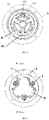
FIG. 2 is a schematic front structure diagram of the axle end grounding device inFIG. 1 . -
FIG. 3 is a left view ofFIG. 2 . -
FIG. 4 is a right view ofFIG. 2 . -
FIG. 5 is a cross-sectional view taken along line A-A inFIG. 4 after a current guide bar is removed. -
FIG. 6 is a schematic front structure diagram of a brush holder assembly inFIG. 2 . -
FIG. 7 is a left view ofFIG. 6 . -
FIG. 8 is a cross-sectional view taken along line A-A inFIG. 7 . -
FIG. 9 is a right view ofFIG. 6 . -
FIG. 10 is an exploded view of the axle end grounding device of the present invention. - In the
figures: 1 , axle box; 2, first bolt; 3, sealing ring; 4, flange mounting base; 5, second bolt; 6, brush holder assembly; 7, current guide bar; 8, end cover; 9, positioning ring; 10, insulating block; 11, brush holder; 12, carbon brush; 13, constant force spring; 14, insulating support; 15, insulating pad; 16, metal gasket. - The present invention will be further described below with reference to specific preferred embodiments, but the scope of protection of the present invention is not limited thereby.
- For the convenience of description, the relative positional relationships of components, such as upper, lower, left, and right, are described according to the layout direction of the accompanying drawings in the specification, and do not limit the structure of this patent.
- As shown in
FIGS. 1 to 10 , an axle end grounding device of the present invention mainly consists ofsealing rings 3, aflange mounting base 4, asecond bolt 5, abrush holder assembly 6, acurrent guide bar 7, anend cover 8, apositioning ring 9,insulating blocks 10, aninsulating support 14, aninsulating pad 15, and ametal gasket 16. - The
flange mounting base 4 is mounted and fixed on an axle box 1 by afirst bolt 2 and themetal gasket 16. Because themetal gasket 16 will not deform due to long-term operation in rigid connection, the fastening torque of thefirst bolt 2 remains unchanged, and theflange mounting base 4 can be stably mounted on the axle box 1. - The
brush holder assembly 6 is assembled in a middle hole of theflange mounting base 4, one end of theflange mounting base 4 is fixedly connected to one end of thebrush holder assembly 6 by thesecond bolt 5, the other end of theflange mounting base 4 clamps and fixes the other end of thebrush holder assembly 6 by means of one end of thepositioning ring 9, and the other end of thepositioning ring 9 is fixedly connected to an inner cavity of the axle box 1. During the running process of a vehicle, thepositioning ring 9 bears the vibration impact of the axle end grounding device, so that thesecond bolt 5 only achieves connection and does not bear shearing force. Theinsulating blocks 10 are fastened to thebrush holder assembly 6, and theinsulating blocks 10 axially confine thepositioning ring 9 in the middle hole of theflange mounting base 4, so that theinsulating blocks 10 can not only restrict the disengagement of thepositioning ring 9, but also realize the insulation between thepositioning ring 9 and thebrush holder assembly 6. The arrangement of thepositioning ring 9 and theinsulating blocks 10 ensures the integrity of the axle end grounding device during delivery. - The
flange mounting base 4 and thebrush holder assembly 6 are insulated by theinsulating support 14, and thesecond bolt 5 and theflange mounting base 4 are insulated by theinsulating pad 15. Theinsulating pad 15 is a non-metallic part, which may deform under long-term operation in a rigid connection, resulting in a decrease in the fastening torque of thesecond bolt 5, thereby causing the fastening failure of thesecond bolt 5. However, because the entirebrush holder assembly 6 is assembled in the middle hole of theflange mounting base 4, even if thesecond bolt 5 fails, thebrush holder assembly 6 will not be disengaged, and there will be no safety hazard. - The
brush holder assembly 6 includes abrush holder 11, threecarbon brushes 12 are supported and mounted in thebrush holder 11 byconstant force springs 13, acurrent guide bar 7 is fixedly connected to the outside of thebrush holder 11 by bolts, and current guide wires of thecarbon brushes 12 are electrically connected to the inside of thebrush holder 11. During operation, thecurrent guide bar 7 is connected to a vehicle current return circuit, so that current flows from thecurrent guide bar 7 into thebrush holder 11, then flows into thecarbon brushes 12 via thebrush holder 11, and finally flows into an axle, a wheel and a rail in sequence via thecarbon brushes 12 to achieve grounding current return. The outer ends of the carbon brushes 12 (the outer end of the brush holder 11) are sealed by theend cover 8. - In order to ensure the sealing and waterproofing of the
carbon brushes 12, the outer end of thebrush holder 11 is sealed by theend cover 8, asealing ring 3 is arranged between theend cover 8 and a mounting surface of thebrush holder 11, meanwhile, thesealing ring 3 is also respectively arranged between theinsulating support 14 and theflange mounting base 4 and between theinsulating support 14 and the mounting surface of thebrush holder 11, and thesealing ring 3 is also arranged between theflange mounting base 4 and a mounting surface of the axle box 1. - The forgoing descriptions are only preferred embodiments of the present application, and do not limit the present application in any form. Although the present application is disclosed above with the preferred embodiments, the present application is not limited thereto. Some variations or modifications made by any skilled person familiar with the art using the disclosed technical contents without departing from the scope of the technical solution of the present application are equivalent to the embodiments, and all fall within the scope of the technical solution.
Claims (5)
- An axle end grounding device, comprising a brush holder assembly (6) and a flange mounting base, wherein the brush holder assembly is mounted in a middle hole of the flange mounting base (4) in an electrical isolation manner, and one end of the brush holder assembly is fixedly connected to one end of the flange mounting base by a second bolt (5); the other end of the brush holder assembly is mounted in the middle hole of the other end of the flange mounting base in a fitting manner by means of one end of a positioning ring (9), the other end of the positioning ring is mounted in an axle box (1) in a fitting manner, the positioning ring (9) is axially limited by an insulating block (10), and the flange mounting base is fixedly mounted on the axle box (1) by a first bolt (2) and a metal gasket.
- The axle end grounding device according to claim 1, wherein an insulating support (14) is arranged between the flange mounting base and the brush holder assembly, and an insulating pad (15) is arranged between the second bolt and the flange mounting base.
- The axle end grounding device according to claim 1, wherein the brush holder assembly comprises a brush holder (11), a carbon brush (12) is supported and mounted in the brush holder by a constant force spring (13), one end of a current guide wire of the carbon brush (12) is fixedly connected to the brush holder, and the brush holder is fixedly connected to a current guide bar (7) connected to a vehicle current return circuit.
- The axle end grounding device according to claim 3, wherein the outer end of the brush holder (11) is sealed by an end cover (8), and a sealing ring is arranged between the brush holder and the end cover.
- The axle end grounding device according to claim 2, wherein a sealing ring is respectively arranged between the insulating support and the flange mounting base and between the insulating support and a mounting surface of the brush holder, and between the flange mounting base and a mounting surface of the axle box.
Applications Claiming Priority (2)
| Application Number | Priority Date | Filing Date | Title |
|---|---|---|---|
| CN201911258753.1A CN111002874B (en) | 2019-12-10 | 2019-12-10 | A shaft end grounding device |
| PCT/CN2020/131278 WO2021115120A1 (en) | 2019-12-10 | 2020-11-25 | Shaft end grounding device |
Publications (2)
| Publication Number | Publication Date |
|---|---|
| EP4044376A1 true EP4044376A1 (en) | 2022-08-17 |
| EP4044376A4 EP4044376A4 (en) | 2023-11-08 |
Family
ID=70115158
Family Applications (1)
| Application Number | Title | Priority Date | Filing Date |
|---|---|---|---|
| EP20899952.4A Withdrawn EP4044376A4 (en) | 2019-12-10 | 2020-11-25 | Shaft end grounding device |
Country Status (3)
| Country | Link |
|---|---|
| EP (1) | EP4044376A4 (en) |
| CN (1) | CN111002874B (en) |
| WO (1) | WO2021115120A1 (en) |
Cited By (1)
| Publication number | Priority date | Publication date | Assignee | Title |
|---|---|---|---|---|
| RU236912U1 (en) * | 2025-03-04 | 2025-08-28 | Акционерное общество "Производственно-коммерческая фирма "Промтехсервис" | Current-discharge device for subway cars |
Families Citing this family (4)
| Publication number | Priority date | Publication date | Assignee | Title |
|---|---|---|---|---|
| CN111002874B (en) * | 2019-12-10 | 2023-07-11 | 中车株洲电力机车有限公司 | A shaft end grounding device |
| CN111775993B (en) * | 2020-06-30 | 2021-09-10 | 中车青岛四方机车车辆股份有限公司 | Axle head earthing device, wheel pair and rail vehicle |
| CN113904188B (en) * | 2021-09-09 | 2024-01-19 | 中车太原机车车辆有限公司 | Railway wagon bearing grounding device |
| CN113823927B (en) * | 2021-11-04 | 2025-09-12 | 青岛四方阿尔斯通铁路运输设备有限公司 | A rolling contact bogie axle end grounding device structure |
Family Cites Families (14)
| Publication number | Priority date | Publication date | Assignee | Title |
|---|---|---|---|---|
| DE4127336A1 (en) * | 1991-08-19 | 1993-02-25 | Schunk Metall & Kunststoff | HOLDING DEVICE FOR BRUSH VEHICLES USED AS RE-CURRENT AND / OR EARTHING CONTACT BRUSHES AND METHOD FOR PRODUCING SUCH A HOLDING DEVICE |
| CN2389090Y (en) * | 1999-09-28 | 2000-07-26 | 株洲九方机车配件有限公司 | Earthing device |
| JP4055457B2 (en) * | 2002-04-09 | 2008-03-05 | 日立化成工業株式会社 | Ground brush device |
| CN2654421Y (en) * | 2003-11-24 | 2004-11-10 | 湘潭电机股份有限公司 | Shaft terminal contact type earthing device |
| CN201046675Y (en) * | 2007-06-22 | 2008-04-16 | 大同市东方机车配件有限公司 | Electric locomotive earthing device |
| CN201142509Y (en) * | 2007-10-18 | 2008-10-29 | 株洲九方电器设备有限公司 | Axle head grounding device |
| CN202127102U (en) * | 2011-02-17 | 2012-01-25 | 赛锐(青岛)自动化技术有限公司 | Grounding device for bogie of electric locomotive |
| CN203485921U (en) * | 2013-08-16 | 2014-03-19 | 上海中电罗莱电气有限公司 | Grounding device |
| CN203496816U (en) * | 2013-09-23 | 2014-03-26 | 常州朗锐东洋传动技术有限公司 | Grounding device of metro vehicle gearbox |
| CN106207507B (en) * | 2016-07-19 | 2019-05-17 | 辽宁红德电碳制品有限公司 | CRH EMU grounding device |
| CN206718882U (en) * | 2017-01-23 | 2017-12-08 | 长城汽车股份有限公司 | Wheel ring flange and hub for vehicle wheel structure |
| CN207466417U (en) | 2017-11-09 | 2018-06-08 | 崔明 | A kind of railcar axle head grounding device |
| CN208299064U (en) * | 2018-07-03 | 2018-12-28 | 四川城际轨道交通材料有限责任公司 | A kind of earthing or grounding means |
| CN111002874B (en) * | 2019-12-10 | 2023-07-11 | 中车株洲电力机车有限公司 | A shaft end grounding device |
-
2019
- 2019-12-10 CN CN201911258753.1A patent/CN111002874B/en not_active Expired - Fee Related
-
2020
- 2020-11-25 WO PCT/CN2020/131278 patent/WO2021115120A1/en not_active Ceased
- 2020-11-25 EP EP20899952.4A patent/EP4044376A4/en not_active Withdrawn
Cited By (1)
| Publication number | Priority date | Publication date | Assignee | Title |
|---|---|---|---|---|
| RU236912U1 (en) * | 2025-03-04 | 2025-08-28 | Акционерное общество "Производственно-коммерческая фирма "Промтехсервис" | Current-discharge device for subway cars |
Also Published As
| Publication number | Publication date |
|---|---|
| EP4044376A4 (en) | 2023-11-08 |
| WO2021115120A1 (en) | 2021-06-17 |
| CN111002874B (en) | 2023-07-11 |
| CN111002874A (en) | 2020-04-14 |
Similar Documents
| Publication | Publication Date | Title |
|---|---|---|
| CN111002874B (en) | A shaft end grounding device | |
| US20150171604A1 (en) | Connection structure between main transformer and high-voltage device box and railcar including same | |
| CN105305706A (en) | Wiring improvement method and wiring apparatus for outgoing line of alternating current frequency conversion traction motor for track traffic vehicles | |
| CN205336020U (en) | A termination that is used for track transportation vehicles with exchanging frequency conversion traction motor lead -out wire | |
| CN208299064U (en) | A kind of earthing or grounding means | |
| CN102537209A (en) | Wire rope locking positioning device and method | |
| CN102398605B (en) | Sealing device, locomotive and hermetic connecting method | |
| CN112864751B (en) | Rail vehicle earthing device | |
| CN219610758U (en) | Grounding device for suspension type monorail vehicle | |
| CN220440346U (en) | Power cable anti-galloping device | |
| CN223797628U (en) | Cable terminal fracture prevention device | |
| CN211442292U (en) | High-voltage cable assembly and rail train | |
| CN203839892U (en) | Phase-to-phase spacer | |
| CN209700442U (en) | A kind of railway contact line low clearance suspension arrangement | |
| CN210882126U (en) | Insulating guide post type axle box positioning structure | |
| CN106207507A (en) | CRH EMUs grounding device | |
| CN219980012U (en) | Single carbon brush ground return device | |
| CN212861096U (en) | Shaft end grounding reflux device | |
| CN219610757U (en) | Railway vehicle bearing anti-over-power device and railway vehicle | |
| CN205160277U (en) | Electric automobile is with electronic power assisted steering pump second grade insulator arrangement | |
| CN113904188B (en) | Railway wagon bearing grounding device | |
| CN217882241U (en) | City rail earthing device | |
| CN103481845A (en) | Grounding device of metro vehicle gearbox | |
| CN214848332U (en) | High-voltage grounding switch transmission device | |
| CN202340060U (en) | Switch cabinet friction ground connector |
Legal Events
| Date | Code | Title | Description |
|---|---|---|---|
| STAA | Information on the status of an ep patent application or granted ep patent |
Free format text: STATUS: THE INTERNATIONAL PUBLICATION HAS BEEN MADE |
|
| PUAI | Public reference made under article 153(3) epc to a published international application that has entered the european phase |
Free format text: ORIGINAL CODE: 0009012 |
|
| STAA | Information on the status of an ep patent application or granted ep patent |
Free format text: STATUS: REQUEST FOR EXAMINATION WAS MADE |
|
| 17P | Request for examination filed |
Effective date: 20220509 |
|
| AK | Designated contracting states |
Kind code of ref document: A1 Designated state(s): AL AT BE BG CH CY CZ DE DK EE ES FI FR GB GR HR HU IE IS IT LI LT LU LV MC MK MT NL NO PL PT RO RS SE SI SK SM TR |
|
| DAV | Request for validation of the european patent (deleted) | ||
| DAX | Request for extension of the european patent (deleted) | ||
| A4 | Supplementary search report drawn up and despatched |
Effective date: 20231006 |
|
| RIC1 | Information provided on ipc code assigned before grant |
Ipc: H01R 39/39 20060101ALI20230929BHEP Ipc: H01R 39/38 20060101ALI20230929BHEP Ipc: B60L 3/00 20190101ALI20230929BHEP Ipc: B61F 15/28 20060101ALI20230929BHEP Ipc: B60M 5/00 20060101ALI20230929BHEP Ipc: H01R 4/66 20060101AFI20230929BHEP |
|
| STAA | Information on the status of an ep patent application or granted ep patent |
Free format text: STATUS: THE APPLICATION HAS BEEN WITHDRAWN |
|
| 18W | Application withdrawn |
Effective date: 20240902 |