EP4044356B1 - Collector plate and cylindrical lithium battery - Google Patents
Collector plate and cylindrical lithium battery Download PDFInfo
- Publication number
- EP4044356B1 EP4044356B1 EP21870549.9A EP21870549A EP4044356B1 EP 4044356 B1 EP4044356 B1 EP 4044356B1 EP 21870549 A EP21870549 A EP 21870549A EP 4044356 B1 EP4044356 B1 EP 4044356B1
- Authority
- EP
- European Patent Office
- Prior art keywords
- current collecting
- collecting plate
- circular current
- circular
- grooves
- Prior art date
- Legal status (The legal status is an assumption and is not a legal conclusion. Google has not performed a legal analysis and makes no representation as to the accuracy of the status listed.)
- Active
Links
Images
Classifications
-
- H—ELECTRICITY
- H01—ELECTRIC ELEMENTS
- H01M—PROCESSES OR MEANS, e.g. BATTERIES, FOR THE DIRECT CONVERSION OF CHEMICAL ENERGY INTO ELECTRICAL ENERGY
- H01M4/00—Electrodes
- H01M4/02—Electrodes composed of, or comprising, active material
- H01M4/64—Carriers or collectors
- H01M4/66—Selection of materials
-
- H—ELECTRICITY
- H01—ELECTRIC ELEMENTS
- H01M—PROCESSES OR MEANS, e.g. BATTERIES, FOR THE DIRECT CONVERSION OF CHEMICAL ENERGY INTO ELECTRICAL ENERGY
- H01M10/00—Secondary cells; Manufacture thereof
- H01M10/05—Accumulators with non-aqueous electrolyte
- H01M10/052—Li-accumulators
-
- H—ELECTRICITY
- H01—ELECTRIC ELEMENTS
- H01M—PROCESSES OR MEANS, e.g. BATTERIES, FOR THE DIRECT CONVERSION OF CHEMICAL ENERGY INTO ELECTRICAL ENERGY
- H01M4/00—Electrodes
- H01M4/02—Electrodes composed of, or comprising, active material
- H01M4/64—Carriers or collectors
-
- H—ELECTRICITY
- H01—ELECTRIC ELEMENTS
- H01M—PROCESSES OR MEANS, e.g. BATTERIES, FOR THE DIRECT CONVERSION OF CHEMICAL ENERGY INTO ELECTRICAL ENERGY
- H01M4/00—Electrodes
- H01M4/02—Electrodes composed of, or comprising, active material
- H01M4/64—Carriers or collectors
- H01M4/70—Carriers or collectors characterised by shape or form
- H01M4/80—Porous plates, e.g. sintered carriers
-
- H—ELECTRICITY
- H01—ELECTRIC ELEMENTS
- H01M—PROCESSES OR MEANS, e.g. BATTERIES, FOR THE DIRECT CONVERSION OF CHEMICAL ENERGY INTO ELECTRICAL ENERGY
- H01M50/00—Constructional details or processes of manufacture of the non-active parts of electrochemical cells other than fuel cells, e.g. hybrid cells
- H01M50/10—Primary casings; Jackets or wrappings
- H01M50/102—Primary casings; Jackets or wrappings characterised by their shape or physical structure
- H01M50/107—Primary casings; Jackets or wrappings characterised by their shape or physical structure having curved cross-section, e.g. round or elliptic
-
- H—ELECTRICITY
- H01—ELECTRIC ELEMENTS
- H01M—PROCESSES OR MEANS, e.g. BATTERIES, FOR THE DIRECT CONVERSION OF CHEMICAL ENERGY INTO ELECTRICAL ENERGY
- H01M50/00—Constructional details or processes of manufacture of the non-active parts of electrochemical cells other than fuel cells, e.g. hybrid cells
- H01M50/60—Arrangements or processes for filling or topping-up with liquids; Arrangements or processes for draining liquids from casings
- H01M50/609—Arrangements or processes for filling with liquid, e.g. electrolytes
-
- Y—GENERAL TAGGING OF NEW TECHNOLOGICAL DEVELOPMENTS; GENERAL TAGGING OF CROSS-SECTIONAL TECHNOLOGIES SPANNING OVER SEVERAL SECTIONS OF THE IPC; TECHNICAL SUBJECTS COVERED BY FORMER USPC CROSS-REFERENCE ART COLLECTIONS [XRACs] AND DIGESTS
- Y02—TECHNOLOGIES OR APPLICATIONS FOR MITIGATION OR ADAPTATION AGAINST CLIMATE CHANGE
- Y02E—REDUCTION OF GREENHOUSE GAS [GHG] EMISSIONS, RELATED TO ENERGY GENERATION, TRANSMISSION OR DISTRIBUTION
- Y02E60/00—Enabling technologies; Technologies with a potential or indirect contribution to GHG emissions mitigation
- Y02E60/10—Energy storage using batteries
Definitions
- the present application relates to the technical field of lithium battery, and more particularly to a current collecting plate and a cylindrical lithium battery.
- lithium batteries are developing rapidly. Due to the high specific energy, long life, and green environmental protection, lithium batteries have attracted more and more attention, and the lithium batteries will have broad application prospects in electric vehicle power sources and energy storage power sources.
- the existing cylindrical battery includes a battery case, an electrode group arranged in the battery case, a current collecting plate arranged at the end of the electrode group, and the current collecting plate is provided with several liquid guiding holes, the speed and uniformity of the electrolyte permeating the battery electrode group can be accelerated by the arrangement of the several liquid guiding holes.
- the liquid guiding is carried out through the liquid guiding holes on the current collecting plate, so that there is still an area under the current collecting plate that cannot get the electrolyte infiltrated at the first time, resulting in poor penetration consistency of the pole pieces, and the injection takes a long time.
- a Chinese application CN208284552U disclosed speed and homogeneity that electrolyte soaks battery pole group can be accelerated in this application, improves battery filling efficiency and battery quality.
- a Chinese application CN106410102A disclosed a circular anode bus disc with four-segment semicircular tabs.
- the circular anode bus disc comprises an anode bus disc body, a central liquid absorbing hole, liquid absorbing hole groups, four laser welding areas and the tabs, wherein the central liquid absorbing hole, the liquid absorbing hole groups, the four laser welding areas and the tabs are arranged on the anode bus disc body, the central liquid absorbing hole is formed in the center of the anode bus disc body, the four laser welding areas are distributed on the front face of the anode bus disc body evenly, the liquid absorbing hole group and the tab are arranged between each two adjacent laser welding areas, each tab is positioned on the inner side of the corresponding liquid absorbing hole group, and the tabs are formed by outward turnover of sector areas arranged on the anode bus disc body and form a four-segment circular wall.
- An international application WO2007134091A2 disclosed a cylindrical electrochemical cell which includes a first electrode and a second electrode which is a counter electrode to the first electrode, and an electrolyte.
- the first electrode includes a polyanion-based electrode active material.
- a US application US20050260487A1 disclosed a secondary battery includes an electrode group with both positive and negative electrodes and a separator interposed therebetween and a case wherein the electrode group is located.
- a cap assembly is combined with the case, seals it, and is electrically connected to the electrode group.
- An object of an embodiment of the present application is to provide a current collecting plate, in order to solve the technical problem that the penetration consistency of the pole pieces of the cylindrical lithium battery in the art is poor, and the injection takes a long time.
- a current collecting plate which includes: a circular current collecting plate, a center of the circular current collecting plate is provided with a central area, an edge of the circular current collecting plate is provided with at least one notch, and circumferences of concentric circles outside the central area of the circular current collecting plate are respectively provided with liquid guiding holes, a diameter of the liquid guiding hole of the concentric circles on an outer circle on the circular current collecting plate is larger than that of the liquid guiding hole on the concentric circles on an inner circle on the circular current collecting plate, and each liquid guiding hole and the notch are configured for guiding liquid for to a battery electrode group at a bottom of the circular current collecting plate; the circular current collecting plate is provided with a plurality of grooves, and a depth of each groove is greater than a thickness of the circular current collecting plate.
- the circular current collecting plate is provided with a plurality of grooves.
- each of the grooves extends along a radial direction of the circular current collecting plate.
- the grooves are formed by a top surface of the circular current collecting plate being recessed toward a bottom surface of the circular current collecting plate.
- grooves are strip-shaped grooves.
- the circular current collecting plate is a positive electrode current collecting plate, and the central area is provided with a through hole.
- the notch is formed through a thickness direction of the circular current collecting plate.
- the embodiment of the present application provides a cylindrical lithium battery, which includes the current collecting plate above-mentioned.
- the beneficial effect of the current collecting plate provided by the present application is that compared with the prior art, the current collecting plate of the present application is provided with liquid guiding holes and at least one notch is arranged on the edge of the circular current collecting plate, so that any concentric circular electrode sheet (battery electrode group) under the current collecting plate can form a liquid injection channel, then, the liquid injection channel can be formed in any concentric circular pole piece under the current collecting plate at the first time of liquid injection of the cylindrical lithium battery, so as to obtain the penetration of the electrolyte, which can effectively improve the consistency of the electrolyte penetration of the electrode sheet, reduce the time-consuming of liquid injection, and improve the product quality.
- first and second are only used for descriptive purposes, and should not be construed as indicating or implying relative importance or implying the number of indicated technical features. Thus, a feature defined as “first” or “second” may expressly or implicitly includes one or more of that feature.
- plurality means two or more, unless otherwise expressly and specifically defined.
- an embodiment of the present application provides a current collecting plate 100, including a circular current collecting plate 10, a center of the circular current collecting plate 10 is provided with a central area 15, an edge of the circular current collecting plate 10 is provided with at least one notch 11, and circumferences of concentric circles of the circular current collecting plate 10 are respectively provided with a liquid guiding hole 2, and each liquid guiding hole 12 and the notch 11 are configured for guiding liquid for to a battery electrode group at a bottom of the circular current collecting plate 10.
- the current collecting plate 100 provided in the embodiment of the present application is applied to a cylindrical lithium battery.
- the body of the current collecting plate is a circular current collecting plate 10, and at least one notch 11 is provided on the edge of the circular current collecting plate 10, or a plurality of notches 11 are arranged at intervals along the circumferential edge of the circular current collecting plate 10, and at the same time, liquid conducting holes 12 are respectively arranged on the circumferences of the concentric circles of the circular current collecting plate 10.
- the liquid can be guided through each concentric liquid guide hole 12 outside the central area of the circular current collecting plate 10 and the notch 11 at the edge of the circular current collecting plate 10, so that the cylindrical lithium battery can form a liquid injection channel for any concentric circular electrode piece under the current collecting plate 100 at the first time of liquid injection, and then obtain electrolyte penetration, which can effectively improve the consistency of electrode sheets electrolyte penetration, reduce the time-consuming of liquid injection, and improve product quality; therefore, the problem that in the prior art, when guiding liquid through the liquid guiding holes 12 on the current collecting plate, it is easy for a part of the area under the current collecting plate to fail to obtain electrolyte penetration for the first time, can be avoided.
- the diameter of the liquid guiding hole 12 of the concentric circles on an outer circle on the circular current collecting plate 10 is larger than that of the liquid guiding hole 12 on the concentric circles on an inner circle on the circular current collecting plate 10.
- the diameter of the liquid guiding hole 12 of the concentric circles on an outer circle on the circular current collecting plate 10 is larger than that of the liquid guiding hole 12 on the concentric circles on an inner circle on the circular current collecting plate 10, that is, based on the center of the circular current collecting plate 10, a plurality of concentric circles are provided on the circular current collecting plate 10, the inner circle is the concentric circles with a smaller radius than the other concentric circles, and the outer circle is the concentric circles with a larger radius than the other concentric circles.
- the large-diameter liquid conducting holes 12 are adapted to the circular current collecting plate 10 to meet the requirements of the large area of the outer ring electrode sheet for electrolyte, to ensure product quality.
- the circular current collecting plate 10 is provided with a plurality of grooves 13.
- the plurality of grooves 13 are provided on the circular current collecting plate 10, and the bottoms of the grooves 13 protrude from the bottom surface of the circular current collecting plate 10, in this way, the concave surface on the end surface of the battery electrode group below the circular current collecting plate 10 is matched, so that the current collecting plate and the end surface of the electrode group can be better positioned and fixed, which is convenient for laser welding, improves the production efficiency of the product, and reduces the production cost of the product and improves the market competitiveness of the product, compared with the end surface of the existing battery electrode group as a whole, the welding plate is formed after the whole end surface is flattened.
- the circular current collecting plate 10 is provided with the grooves 13 corresponding to the end surface of the battery electrode group to be flattened to facilitate welding, and other parts of the end surface of the battery electrode group are still in an upright state. It is easier to penetrate and improve the penetration efficiency of the electrolyte.
- each of the grooves 13 is extended along the radial direction of the circular current collecting plate 10.
- the grooves 13 are strip-shaped grooves.
- each groove 13 extends along the radial direction of the circular current collecting plate 10, that is, the center of the circular current collecting plate 10 is arranged in a reflective shape toward the circumferential direction of the circular current collecting plate 10, in this way, it is more stable and reliable when it is matched with the end surface of the electrode group.
- the grooves 13 are formed by a top surface of the circular current collecting plate 10 being recessed toward a bottom surface of the circular current collecting plate 10.
- a depth of each groove 13 is greater than a thickness of the circular current collecting plate 10.
- the grooves 13 are integrally formed by the top surface of the circular current collecting plate 10 being recessed toward the bottom surface thereof, so that the bottom of the groove 13 protrudes from the bottom surface of the circular current collecting plate 10, so that the grooves 13 form a convex structure on the bottom surface of the circular current collecting plate 10, so that it matches with the concave surface of the end surface of the electrode group, that is, the convex structure is inserted into the concave surface of the end surface of the electrode group to play the function of positioning and fixing.
- the circular current collecting plate 10 is a positive current collecting plate, and the central area 15 is provided with a through hole 14.
- the through hole 14 is provided in the central area 15 of the circular current collecting plate 10 to facilitate the insertion of the welding needle into the cell, and to complete the welding of the negative electrode liquid collecting sheet at the bottom of the cell and the battery shell, and the setting of the through hole 14 is used to facilitate the release of gas which is formed via electrochemical reactions during formation process, and the pressure inside the cylindrical lithium battery is released in time to ensure the safety of the battery.
- the notches 11 are formed through the thickness direction of the circular current collecting plate 10.
- each notch 11 are in the shape of an arc, specifically, each notch 11 is a semicircle, and the semicircle notch 11 runs through the entire circular current collecting plate 10.
- An embodiment of the present application provides a cylindrical lithium battery, including the current collecting plate 100 described in any of the above embodiments.
- a cylindrical lithium battery includes a battery case and an electrode group disposed in the battery case, and the current collecting plate 100 in any of the above embodiments is disposed at an end of the electrode group.
- the cylindrical lithium battery provided by the embodiments of the present application has the current collecting plate 100 provided by any of the above embodiments, therefore, it has all the beneficial effects of the current collecting plate 100 provided by any of the above embodiments, and will not be repeated here.
- the current collecting plate provided in this embodiment works as follows:
- the current collecting plate is applied to the cylindrical lithium battery.
- the body of the current collecting plate is a circular current collecting plate 10, and a plurality of notches 11 are arranged on the edge of the circular current collecting plate 10, the notches are semicircular, and the notches are arranged at intervals along the circumferential edge of the circular current collecting plate 10, and at the same time, liquid guiding holes 12 are provided on the circumferences of the concentric circles of the circular current collecting plate 10 respectively.
- the liquid can be guided through each concentric liquid guide hole 12 outside the central area of the circular current collecting plate 10 and the notch 11 at the edge of the circular current collecting plate 10, so that the cylindrical lithium battery can form a liquid injection channel for any concentric circular electrode piece under the current collecting plate 100 at the first time of liquid inj ection, and then obtain electrolyte penetration, which can effectively improve the consistency of electrode sheets electrolyte penetration, reduce the time-consuming of liquid injection, and improve product quality; therefore, the problem that in the prior art, when guiding liquid through the liquid guiding holes 12 on the current collecting plate, it is easy for a part of the area under the current collecting plate to fail to obtain electrolyte penetration for the first time, can be avoided.
- each groove 13 is extended along the radial direction of the circular current collecting plate 10, the grooves 13 are strip-shaped grooves, and the grooves 13 are formed by the top surface of the circular current collecting plate 10 being recessed toward the bottom surface thereof, and the depth of each groove 13 is greater than the thickness of the circular current collecting plate 10, so that it matches with the concave surface of the end surface of the electrode group, to make the current collecting plate and the end surface of the electrode group better positioned and fixed, which is convenient for laser welding, improves the production efficiency of the product, reduces the production cost of the product, and improves the market competitiveness of the product.
- the current collecting plate and the cylindrical lithium battery provided by the present application are provided with liquid guiding holes and at least one notch is arranged on the edge of the circular current collecting plate, so that any concentric circular electrode sheet (battery electrode group) under the current collecting plate can form a liquid injection channel, then, the liquid injection channel can be formed in any concentric circular pole piece under the current collecting plate at the first time of liquid injection of the cylindrical lithium battery, so as to obtain the penetration of the electrolyte, which can effectively improve the consistency of the electrolyte penetration of the electrode sheet, reduce the time-consuming of liquid injection, and improve the product quality.
Landscapes
- Chemical & Material Sciences (AREA)
- Chemical Kinetics & Catalysis (AREA)
- Electrochemistry (AREA)
- General Chemical & Material Sciences (AREA)
- Engineering & Computer Science (AREA)
- Manufacturing & Machinery (AREA)
- Materials Engineering (AREA)
- Secondary Cells (AREA)
- Cell Electrode Carriers And Collectors (AREA)
- Connection Of Batteries Or Terminals (AREA)
- Battery Electrode And Active Subsutance (AREA)
- Primary Cells (AREA)
- Filling, Topping-Up Batteries (AREA)
Description
- The present application relates to the technical field of lithium battery, and more particularly to a current collecting plate and a cylindrical lithium battery.
- With the development of economy and society, batteries, especially lithium batteries, are developing rapidly. Due to the high specific energy, long life, and green environmental protection, lithium batteries have attracted more and more attention, and the lithium batteries will have broad application prospects in electric vehicle power sources and energy storage power sources.
- The existing cylindrical battery includes a battery case, an electrode group arranged in the battery case, a current collecting plate arranged at the end of the electrode group, and the current collecting plate is provided with several liquid guiding holes, the speed and uniformity of the electrolyte permeating the battery electrode group can be accelerated by the arrangement of the several liquid guiding holes. However, the liquid guiding is carried out through the liquid guiding holes on the current collecting plate, so that there is still an area under the current collecting plate that cannot get the electrolyte infiltrated at the first time, resulting in poor penetration consistency of the pole pieces, and the injection takes a long time.
- A Chinese application
CN208284552U disclosed speed and homogeneity that electrolyte soaks battery pole group can be accelerated in this application, improves battery filling efficiency and battery quality. - A Chinese application
CN106410102A disclosed a circular anode bus disc with four-segment semicircular tabs. The circular anode bus disc comprises an anode bus disc body, a central liquid absorbing hole, liquid absorbing hole groups, four laser welding areas and the tabs, wherein the central liquid absorbing hole, the liquid absorbing hole groups, the four laser welding areas and the tabs are arranged on the anode bus disc body, the central liquid absorbing hole is formed in the center of the anode bus disc body, the four laser welding areas are distributed on the front face of the anode bus disc body evenly, the liquid absorbing hole group and the tab are arranged between each two adjacent laser welding areas, each tab is positioned on the inner side of the corresponding liquid absorbing hole group, and the tabs are formed by outward turnover of sector areas arranged on the anode bus disc body and form a four-segment circular wall. - An international application
WO2007134091A2 disclosed a cylindrical electrochemical cell which includes a first electrode and a second electrode which is a counter electrode to the first electrode, and an electrolyte. The first electrode includes a polyanion-based electrode active material. - A US application
US20050260487A1 disclosed a secondary battery includes an electrode group with both positive and negative electrodes and a separator interposed therebetween and a case wherein the electrode group is located. A cap assembly is combined with the case, seals it, and is electrically connected to the electrode group. - An object of an embodiment of the present application is to provide a current collecting plate, in order to solve the technical problem that the penetration consistency of the pole pieces of the cylindrical lithium battery in the art is poor, and the injection takes a long time.
- The invention is defined in the appended claims.
- In order to solve above object, the technical solution adopted in the present application is to provide a current collecting plate, which includes:
a circular current collecting plate, a center of the circular current collecting plate is provided with a central area, an edge of the circular current collecting plate is provided with at least one notch, and circumferences of concentric circles outside the central area of the circular current collecting plate are respectively provided with liquid guiding holes, a diameter of the liquid guiding hole of the concentric circles on an outer circle on the circular current collecting plate is larger than that of the liquid guiding hole on the concentric circles on an inner circle on the circular current collecting plate, and each liquid guiding hole and the notch are configured for guiding liquid for to a battery electrode group at a bottom of the circular current collecting plate; the circular current collecting plate is provided with a plurality of grooves, and a depth of each groove is greater than a thickness of the circular current collecting plate. - Further, the circular current collecting plate is provided with a plurality of grooves.
- Further, each of the grooves extends along a radial direction of the circular current collecting plate.
- Further, the grooves are formed by a top surface of the circular current collecting plate being recessed toward a bottom surface of the circular current collecting plate.
- Further, the grooves are strip-shaped grooves.
- Further, the circular current collecting plate is a positive electrode current collecting plate, and the central area is provided with a through hole.
- Further, the notch is formed through a thickness direction of the circular current collecting plate.
- The embodiment of the present application provides a cylindrical lithium battery, which includes the current collecting plate above-mentioned.
- The beneficial effect of the current collecting plate provided by the present application is that compared with the prior art, the current collecting plate of the present application is provided with liquid guiding holes and at least one notch is arranged on the edge of the circular current collecting plate, so that any concentric circular electrode sheet (battery electrode group) under the current collecting plate can form a liquid injection channel, then, the liquid injection channel can be formed in any concentric circular pole piece under the current collecting plate at the first time of liquid injection of the cylindrical lithium battery, so as to obtain the penetration of the electrolyte, which can effectively improve the consistency of the electrolyte penetration of the electrode sheet, reduce the time-consuming of liquid injection, and improve the product quality.
- In order to illustrate the technical solutions in the embodiments of the present application more clearly, the following briefly introduces the accompanying drawings that need to be used in the description of the embodiments or the prior art. Obviously, the drawings in the following description are only for the present application. In some embodiments, for those of ordinary skill in the art, other drawings can also be obtained according to these drawings without any creative effort.
-
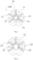
Fig. 1 is a schematic structural diagram of a current collecting plate provided by an embodiment of the present application as a positive electrode current collecting plate; and -
Fig. 2 is a schematic structural diagram of a current collecting plate provided by an embodiment of the present application as a negative electrode current collecting plate. - The details of the symbols involved in the above drawings are as follows:
- 100-current collecting plate;
- 10-circular current collecting plate; 11-notch; 12-liquid guiding hole; 13-groove; 14-through hole; 15-central area.
- In order to make the technical problems, technical solutions and beneficial effects to be solved by the present application clearer, the present application will be described in further detail below with reference to the accompanying drawings and embodiments. It should be understood that the specific embodiments described herein are only used to explain the present application, but not to limit the present application.
- It should be noted that when an element is referred to as being "fixed to" or "disposed on" another element, it can be directly on the other element or indirectly on the other element. When an element is referred to as being "connected to" another element, it can be directly connected to the other element or indirectly connected to the other element.
- It is to be understood that the terms "length", "width", "upper", "lower", "front", "rear", "left", "right", "vertical", "horizontal", "top" , "bottom", "inside", "outside", etc. indicate the orientation or positional relationship based on the orientation or positional relationship shown in the accompanying drawings, only for the convenience of describing the present application and simplifying the description, rather than indicating or implying the indicated a device or element must have a particular orientation, be constructed and operate in a particular orientation, and therefore should not be construed as a limitation of the present application.
- In addition, the terms "first" and "second" are only used for descriptive purposes, and should not be construed as indicating or implying relative importance or implying the number of indicated technical features. Thus, a feature defined as "first" or "second" may expressly or implicitly includes one or more of that feature. In the description of the present application, "plurality" means two or more, unless otherwise expressly and specifically defined.
- In order to illustrate the technical solutions described in the present application, a detailed description is given below with reference to the specific drawings and embodiments.
- As shown in
Fig. 1 and Fig. 2 , an embodiment of the present application provides acurrent collecting plate 100, including a circularcurrent collecting plate 10, a center of the circularcurrent collecting plate 10 is provided with acentral area 15, an edge of the circularcurrent collecting plate 10 is provided with at least onenotch 11, and circumferences of concentric circles of the circularcurrent collecting plate 10 are respectively provided with a liquid guiding hole 2, and eachliquid guiding hole 12 and thenotch 11 are configured for guiding liquid for to a battery electrode group at a bottom of the circularcurrent collecting plate 10. - The
current collecting plate 100 provided in the embodiment of the present application is applied to a cylindrical lithium battery. The body of the current collecting plate is a circularcurrent collecting plate 10, and at least onenotch 11 is provided on the edge of the circularcurrent collecting plate 10, or a plurality ofnotches 11 are arranged at intervals along the circumferential edge of the circularcurrent collecting plate 10, and at the same time, liquid conductingholes 12 are respectively arranged on the circumferences of the concentric circles of the circularcurrent collecting plate 10. When the battery electrode group (that is the concentric electrode sheets) on the bottom of the circularcurrent collecting plate 10 is injected, the liquid can be guided through each concentricliquid guide hole 12 outside the central area of the circularcurrent collecting plate 10 and thenotch 11 at the edge of the circularcurrent collecting plate 10, so that the cylindrical lithium battery can form a liquid injection channel for any concentric circular electrode piece under thecurrent collecting plate 100 at the first time of liquid injection, and then obtain electrolyte penetration, which can effectively improve the consistency of electrode sheets electrolyte penetration, reduce the time-consuming of liquid injection, and improve product quality; therefore, the problem that in the prior art, when guiding liquid through the liquid guidingholes 12 on the current collecting plate, it is easy for a part of the area under the current collecting plate to fail to obtain electrolyte penetration for the first time, can be avoided. - In some embodiments of the present application, optionally, as shown in
Fig. 1 and Fig. 2 , the diameter of theliquid guiding hole 12 of the concentric circles on an outer circle on the circularcurrent collecting plate 10 is larger than that of theliquid guiding hole 12 on the concentric circles on an inner circle on the circularcurrent collecting plate 10. - In the embodiment, the diameter of the
liquid guiding hole 12 of the concentric circles on an outer circle on the circularcurrent collecting plate 10 is larger than that of theliquid guiding hole 12 on the concentric circles on an inner circle on the circularcurrent collecting plate 10, that is, based on the center of the circularcurrent collecting plate 10, a plurality of concentric circles are provided on the circularcurrent collecting plate 10, the inner circle is the concentric circles with a smaller radius than the other concentric circles, and the outer circle is the concentric circles with a larger radius than the other concentric circles. With the diameter of theliquid guiding hole 12 of the concentric circles on the outer circle on the circularcurrent collecting plate 10 is larger than that of theliquid guiding hole 12 on the concentric circles on the inner circle on the circularcurrent collecting plate 10, the electrolyte of the electrode sheets under the current collecting plate can be penetrated more, since a plurality of outer circle electrode sheets are provided, which results in a large area and a large amount of electrolyte required. Therefore, the large-diameterliquid conducting holes 12 are adapted to the circularcurrent collecting plate 10 to meet the requirements of the large area of the outer ring electrode sheet for electrolyte, to ensure product quality. - In some embodiments of the present application, optionally, as shown in
Fig. 1 and Fig. 2 , the circularcurrent collecting plate 10 is provided with a plurality ofgrooves 13. - In the embodiment, the plurality of
grooves 13 are provided on the circularcurrent collecting plate 10, and the bottoms of thegrooves 13 protrude from the bottom surface of the circularcurrent collecting plate 10, in this way, the concave surface on the end surface of the battery electrode group below the circularcurrent collecting plate 10 is matched, so that the current collecting plate and the end surface of the electrode group can be better positioned and fixed, which is convenient for laser welding, improves the production efficiency of the product, and reduces the production cost of the product and improves the market competitiveness of the product, compared with the end surface of the existing battery electrode group as a whole, the welding plate is formed after the whole end surface is flattened. The circularcurrent collecting plate 10 is provided with thegrooves 13 corresponding to the end surface of the battery electrode group to be flattened to facilitate welding, and other parts of the end surface of the battery electrode group are still in an upright state. It is easier to penetrate and improve the penetration efficiency of the electrolyte. - In the above-mentioned embodiment of the present application, optionally, as shown in
Fig. 1 and Fig. 2 , each of thegrooves 13 is extended along the radial direction of the circularcurrent collecting plate 10. Optionally, thegrooves 13 are strip-shaped grooves. - In the embodiment, each
groove 13 extends along the radial direction of the circularcurrent collecting plate 10, that is, the center of the circularcurrent collecting plate 10 is arranged in a reflective shape toward the circumferential direction of the circularcurrent collecting plate 10, in this way, it is more stable and reliable when it is matched with the end surface of the electrode group. - In the above-mentioned embodiment of the present application, optionally, as shown in
Fig. 1 and Fig. 2 , thegrooves 13 are formed by a top surface of the circularcurrent collecting plate 10 being recessed toward a bottom surface of the circularcurrent collecting plate 10. Optionally, a depth of eachgroove 13 is greater than a thickness of the circularcurrent collecting plate 10. - In the embodiment, specifically, the
grooves 13 are integrally formed by the top surface of the circular current collectingplate 10 being recessed toward the bottom surface thereof, so that the bottom of thegroove 13 protrudes from the bottom surface of the circular current collectingplate 10, so that thegrooves 13 form a convex structure on the bottom surface of the circular current collectingplate 10, so that it matches with the concave surface of the end surface of the electrode group, that is, the convex structure is inserted into the concave surface of the end surface of the electrode group to play the function of positioning and fixing. - In some embodiments of the present application, optionally, as shown in
Fig. 1 , the circular current collectingplate 10 is a positive current collecting plate, and thecentral area 15 is provided with a throughhole 14. - In the embodiment, when the current collecting plate is the positive current collecting plate, the through
hole 14 is provided in thecentral area 15 of the circular current collectingplate 10 to facilitate the insertion of the welding needle into the cell, and to complete the welding of the negative electrode liquid collecting sheet at the bottom of the cell and the battery shell, and the setting of the throughhole 14 is used to facilitate the release of gas which is formed via electrochemical reactions during formation process, and the pressure inside the cylindrical lithium battery is released in time to ensure the safety of the battery. - In some embodiments of the present application, optionally, as shown in
Fig. 1 and Fig. 2 , thenotches 11 are formed through the thickness direction of the circular current collectingplate 10. - In the embodiment, each
notch 11 are in the shape of an arc, specifically, eachnotch 11 is a semicircle, and thesemicircle notch 11 runs through the entire circular current collectingplate 10. - An embodiment of the present application provides a cylindrical lithium battery, including the
current collecting plate 100 described in any of the above embodiments. - In some embodiments of the present application, optionally, a cylindrical lithium battery includes a battery case and an electrode group disposed in the battery case, and the
current collecting plate 100 in any of the above embodiments is disposed at an end of the electrode group. - The cylindrical lithium battery provided by the embodiments of the present application has the
current collecting plate 100 provided by any of the above embodiments, therefore, it has all the beneficial effects of thecurrent collecting plate 100 provided by any of the above embodiments, and will not be repeated here. - Specifically, as shown in
Fig. 1 and Fig. 2 , the current collecting plate provided in this embodiment works as follows:
The current collecting plate is applied to the cylindrical lithium battery. The body of the current collecting plate is a circular current collectingplate 10, and a plurality ofnotches 11 are arranged on the edge of the circular current collectingplate 10, the notches are semicircular, and the notches are arranged at intervals along the circumferential edge of the circular current collectingplate 10, and at the same time,liquid guiding holes 12 are provided on the circumferences of the concentric circles of the circular current collectingplate 10 respectively. When the battery electrode group (that is the concentric electrode sheets) on the bottom of the circular current collectingplate 10 is injected, the liquid can be guided through each concentricliquid guide hole 12 outside the central area of the circular current collectingplate 10 and thenotch 11 at the edge of the circular current collectingplate 10, so that the cylindrical lithium battery can form a liquid injection channel for any concentric circular electrode piece under thecurrent collecting plate 100 at the first time of liquid inj ection, and then obtain electrolyte penetration, which can effectively improve the consistency of electrode sheets electrolyte penetration, reduce the time-consuming of liquid injection, and improve product quality; therefore, the problem that in the prior art, when guiding liquid through the liquid guiding holes 12 on the current collecting plate, it is easy for a part of the area under the current collecting plate to fail to obtain electrolyte penetration for the first time, can be avoided. In addition, thegrooves 13 can also be provided on the circular current collectingplate 10, eachgroove 13 is extended along the radial direction of the circular current collectingplate 10, thegrooves 13 are strip-shaped grooves, and thegrooves 13 are formed by the top surface of the circular current collectingplate 10 being recessed toward the bottom surface thereof, and the depth of eachgroove 13 is greater than the thickness of the circular current collectingplate 10, so that it matches with the concave surface of the end surface of the electrode group, to make the current collecting plate and the end surface of the electrode group better positioned and fixed, which is convenient for laser welding, improves the production efficiency of the product, reduces the production cost of the product, and improves the market competitiveness of the product. - In summary, the current collecting plate and the cylindrical lithium battery provided by the present application are provided with liquid guiding holes and at least one notch is arranged on the edge of the circular current collecting plate, so that any concentric circular electrode sheet (battery electrode group) under the current collecting plate can form a liquid injection channel, then, the liquid injection channel can be formed in any concentric circular pole piece under the current collecting plate at the first time of liquid injection of the cylindrical lithium battery, so as to obtain the penetration of the electrolyte, which can effectively improve the consistency of the electrolyte penetration of the electrode sheet, reduce the time-consuming of liquid injection, and improve the product quality.
Claims (7)
- A current collecting plate (100), comprising:a circular current collecting plate (10), a center of the circular current collecting plate (10) is provided with a central area (15), an edge of the circular current collecting plate (10) is provided with at least one notch (11), and circumferences of concentric circles outside the central area (15) of the circular current collecting plate (10) are respectively provided with liquid guiding holes (12), a diameter of the liquid guiding hole (12) of the concentric circles on an outer circle on the circular current collecting plate (10) is larger than that of the liquid guiding hole (12) on the concentric circles on an inner circle on the circular current collecting plate (10), and each liquid guiding hole (12) and the notch (11) are configured for guiding liquid for to a battery electrode group at a bottom of the circular current collecting plate (10); andwherein the circular current collecting plate (10) is provided with a plurality of grooves (13), and a depth of each groove (13) is greater than a thickness of the circular current collecting plate (10).
- The current collecting plate according to claim 1, wherein each of the grooves (13) extends along a radial direction of the circular current collecting plate (10).
- The current collecting plate according to claim 1, wherein the grooves (13) are formed by a top surface of the circular current collecting plate (10) being recessed toward a bottom surface of the circular current collecting plate (10).
- The current collecting plate according to claim 3, wherein the grooves (13) are strip-shaped grooves.
- The current collecting plate according to claim 1, wherein the circular current collecting plate (10) is a positive electrode current collecting plate and the central area (15) is provided with a through hole (14).
- The current collecting plate according to claim 1, wherein the notch (11) is formed through a thickness direction of the circular current collecting plate (10).
- A cylindrical lithium battery, comprising the current collecting plate as claimed in any one of claims 1 to 6.
Applications Claiming Priority (2)
| Application Number | Priority Date | Filing Date | Title |
|---|---|---|---|
| CN202011178413.0A CN114512673A (en) | 2020-10-29 | 2020-10-29 | Collector plate and cylindrical lithium battery |
| PCT/CN2021/111287 WO2022088827A1 (en) | 2020-10-29 | 2021-08-06 | Collector plate and cylindrical lithium battery |
Publications (4)
| Publication Number | Publication Date |
|---|---|
| EP4044356A1 EP4044356A1 (en) | 2022-08-17 |
| EP4044356A4 EP4044356A4 (en) | 2024-03-06 |
| EP4044356C0 EP4044356C0 (en) | 2025-01-01 |
| EP4044356B1 true EP4044356B1 (en) | 2025-01-01 |
Family
ID=81383543
Family Applications (1)
| Application Number | Title | Priority Date | Filing Date |
|---|---|---|---|
| EP21870549.9A Active EP4044356B1 (en) | 2020-10-29 | 2021-08-06 | Collector plate and cylindrical lithium battery |
Country Status (6)
| Country | Link |
|---|---|
| US (1) | US20220416254A1 (en) |
| EP (1) | EP4044356B1 (en) |
| JP (1) | JP3244027U (en) |
| CN (1) | CN114512673A (en) |
| HU (1) | HUE070953T2 (en) |
| WO (1) | WO2022088827A1 (en) |
Families Citing this family (7)
| Publication number | Priority date | Publication date | Assignee | Title |
|---|---|---|---|---|
| CN213520238U (en) | 2020-10-29 | 2021-06-22 | 深圳市比克动力电池有限公司 | All-tab cylindrical lithium battery cap and all-tab cylindrical lithium battery |
| CN213520231U (en) | 2020-10-29 | 2021-06-22 | 深圳市比克动力电池有限公司 | New cylindrical lithium battery cap and new cylindrical lithium battery |
| CN218039691U (en) * | 2022-08-08 | 2022-12-13 | 湖北亿纬动力有限公司 | Collector plate and battery |
| CN115241608B (en) * | 2022-08-20 | 2024-03-22 | 深圳市赛尔摩星科技有限公司 | Current collecting plate and cylindrical lithium battery |
| CN221080284U (en) * | 2023-10-31 | 2024-06-04 | 惠州亿纬动力电池有限公司 | lithium battery |
| WO2025182677A1 (en) * | 2024-02-29 | 2025-09-04 | パナソニックIpマネジメント株式会社 | Sealed battery |
| CN119890621B (en) * | 2025-01-10 | 2025-10-31 | 江苏睿恩新能源科技有限公司 | Negative electrode current collecting disc and cylindrical lithium ion battery |
Family Cites Families (14)
| Publication number | Priority date | Publication date | Assignee | Title |
|---|---|---|---|---|
| KR100599792B1 (en) * | 2004-05-19 | 2006-07-13 | 삼성에스디아이 주식회사 | Secondary Battery, Electrode Assembly and Current Collecting Plate Used in the Same |
| JP4606079B2 (en) * | 2004-07-21 | 2011-01-05 | 三洋電機株式会社 | battery |
| JP5051410B2 (en) * | 2005-05-30 | 2012-10-17 | 株式会社Gsユアサ | Sealed battery lead, sealed battery using the lead, and method of manufacturing the battery |
| JP2007250442A (en) * | 2006-03-17 | 2007-09-27 | Sanyo Electric Co Ltd | Nonaqueous electrolyte secondary battery |
| US20070298317A1 (en) * | 2006-05-09 | 2007-12-27 | Ralph Brodd | Secondary electrochemical cell with increased current collecting efficiency |
| CN102306712A (en) * | 2011-08-31 | 2012-01-04 | 华为技术有限公司 | Cylinder battery |
| CN102629688B (en) * | 2012-03-23 | 2015-08-19 | 实联长宜中国控股有限公司 | A cylindrical lithium battery |
| CN204441382U (en) * | 2015-01-23 | 2015-07-01 | 深圳市慧通天下科技股份有限公司 | Cylinder type lithium battery end face weld collector |
| CN107808962B (en) * | 2016-09-08 | 2021-04-13 | Fdk株式会社 | Cylindrical alkaline secondary battery |
| CN106410102B (en) * | 2016-11-09 | 2023-06-27 | 浙江兴海能源科技有限公司 | Circular positive electrode confluence disc with four-section semicircular lugs and connecting method thereof |
| CN206711986U (en) * | 2017-04-06 | 2017-12-05 | 珠海南北能源科技有限公司 | A kind of new cylindrical lithium battery |
| CN208284552U (en) * | 2018-06-01 | 2018-12-25 | 苏州安靠电源有限公司 | The uniform end face weld battery of fluid injection |
| CN211789215U (en) * | 2020-05-21 | 2020-10-27 | 湖南华兴新能源科技有限公司 | Upper gasket of cylindrical battery |
| CN213520044U (en) * | 2020-10-29 | 2021-06-22 | 深圳市比克动力电池有限公司 | Current collector plate and cylindrical lithium battery |
-
2020
- 2020-10-29 CN CN202011178413.0A patent/CN114512673A/en active Pending
-
2021
- 2021-08-06 WO PCT/CN2021/111287 patent/WO2022088827A1/en not_active Ceased
- 2021-08-06 JP JP2022600083U patent/JP3244027U/en active Active
- 2021-08-06 HU HUE21870549A patent/HUE070953T2/en unknown
- 2021-08-06 EP EP21870549.9A patent/EP4044356B1/en active Active
- 2021-08-06 US US17/778,915 patent/US20220416254A1/en not_active Abandoned
Also Published As
| Publication number | Publication date |
|---|---|
| WO2022088827A1 (en) | 2022-05-05 |
| JP3244027U (en) | 2023-10-04 |
| CN114512673A (en) | 2022-05-17 |
| EP4044356A1 (en) | 2022-08-17 |
| US20220416254A1 (en) | 2022-12-29 |
| EP4044356C0 (en) | 2025-01-01 |
| HUE070953T2 (en) | 2025-07-28 |
| EP4044356A4 (en) | 2024-03-06 |
Similar Documents
| Publication | Publication Date | Title |
|---|---|---|
| EP4044356B1 (en) | Collector plate and cylindrical lithium battery | |
| CN217934126U (en) | Battery with a battery cell | |
| CN213520044U (en) | Current collector plate and cylindrical lithium battery | |
| CN217062311U (en) | Cover plate assembly for lithium ion battery, lithium ion battery and vehicle | |
| US20240213630A1 (en) | Lithium battery and method for preparing lithium battery | |
| CN109119674B (en) | Power lithium battery | |
| CN219873942U (en) | Converging disc structure and battery pack | |
| EP4668426A1 (en) | Cover plate assembly, method for manufacturing same, and battery | |
| CN216133955U (en) | A current collector plate and cylindrical battery | |
| US20250132468A1 (en) | Current collector structure and battery pack | |
| CN212323103U (en) | Lithium battery case and lithium battery | |
| CN220324653U (en) | Current collecting disc and tab connection structure, battery cell and lithium battery | |
| CN218887487U (en) | A kind of battery and battery module | |
| CN216133947U (en) | Explosion-proof end cover of cylindrical battery and cylindrical battery | |
| CN215771249U (en) | Lithium ion battery and vehicle comprising same | |
| WO2024045072A1 (en) | Cell, battery, electric device, and manufacturing method for cell | |
| CN223401840U (en) | Current collecting disc and cylindrical battery | |
| EP4589708A1 (en) | Current collector disk and battery | |
| CN220895791U (en) | Cylinder battery assembly that converges | |
| CN222562922U (en) | Confluence sheet | |
| CN220253351U (en) | Cylindrical battery cover plate assembly | |
| CN222775416U (en) | Battery cover and battery | |
| CN222720620U (en) | Battery with improved positive terminal structure | |
| CN221102229U (en) | Cylindrical battery with explosion-proof structure | |
| CN222546413U (en) | Cylindrical cells and cylindrical batteries |
Legal Events
| Date | Code | Title | Description |
|---|---|---|---|
| STAA | Information on the status of an ep patent application or granted ep patent |
Free format text: STATUS: UNKNOWN |
|
| STAA | Information on the status of an ep patent application or granted ep patent |
Free format text: STATUS: THE INTERNATIONAL PUBLICATION HAS BEEN MADE |
|
| PUAI | Public reference made under article 153(3) epc to a published international application that has entered the european phase |
Free format text: ORIGINAL CODE: 0009012 |
|
| STAA | Information on the status of an ep patent application or granted ep patent |
Free format text: STATUS: REQUEST FOR EXAMINATION WAS MADE |
|
| 17P | Request for examination filed |
Effective date: 20220331 |
|
| AK | Designated contracting states |
Kind code of ref document: A1 Designated state(s): AL AT BE BG CH CY CZ DE DK EE ES FI FR GB GR HR HU IE IS IT LI LT LU LV MC MK MT NL NO PL PT RO RS SE SI SK SM TR |
|
| DAV | Request for validation of the european patent (deleted) | ||
| DAX | Request for extension of the european patent (deleted) | ||
| A4 | Supplementary search report drawn up and despatched |
Effective date: 20240202 |
|
| RIC1 | Information provided on ipc code assigned before grant |
Ipc: H01M 50/609 20210101ALI20240129BHEP Ipc: H01M 4/70 20060101ALI20240129BHEP Ipc: H01M 4/64 20060101ALI20240129BHEP Ipc: H01M 50/109 20210101ALI20240129BHEP Ipc: H01M 50/107 20210101ALI20240129BHEP Ipc: H01M 50/538 20210101AFI20240129BHEP |
|
| GRAP | Despatch of communication of intention to grant a patent |
Free format text: ORIGINAL CODE: EPIDOSNIGR1 |
|
| STAA | Information on the status of an ep patent application or granted ep patent |
Free format text: STATUS: GRANT OF PATENT IS INTENDED |
|
| INTG | Intention to grant announced |
Effective date: 20240805 |
|
| GRAS | Grant fee paid |
Free format text: ORIGINAL CODE: EPIDOSNIGR3 |
|
| GRAA | (expected) grant |
Free format text: ORIGINAL CODE: 0009210 |
|
| STAA | Information on the status of an ep patent application or granted ep patent |
Free format text: STATUS: THE PATENT HAS BEEN GRANTED |
|
| AK | Designated contracting states |
Kind code of ref document: B1 Designated state(s): AL AT BE BG CH CY CZ DE DK EE ES FI FR GB GR HR HU IE IS IT LI LT LU LV MC MK MT NL NO PL PT RO RS SE SI SK SM TR |
|
| REG | Reference to a national code |
Ref country code: GB Ref legal event code: FG4D |
|
| REG | Reference to a national code |
Ref country code: CH Ref legal event code: EP |
|
| REG | Reference to a national code |
Ref country code: DE Ref legal event code: R096 Ref document number: 602021024487 Country of ref document: DE |
|
| REG | Reference to a national code |
Ref country code: IE Ref legal event code: FG4D |
|
| U01 | Request for unitary effect filed |
Effective date: 20250128 |
|
| U07 | Unitary effect registered |
Designated state(s): AT BE BG DE DK EE FI FR IT LT LU LV MT NL PT RO SE SI Effective date: 20250203 |
|
| PG25 | Lapsed in a contracting state [announced via postgrant information from national office to epo] |
Ref country code: PL Free format text: LAPSE BECAUSE OF FAILURE TO SUBMIT A TRANSLATION OF THE DESCRIPTION OR TO PAY THE FEE WITHIN THE PRESCRIBED TIME-LIMIT Effective date: 20250101 |
|
| PG25 | Lapsed in a contracting state [announced via postgrant information from national office to epo] |
Ref country code: ES Free format text: LAPSE BECAUSE OF FAILURE TO SUBMIT A TRANSLATION OF THE DESCRIPTION OR TO PAY THE FEE WITHIN THE PRESCRIBED TIME-LIMIT Effective date: 20250101 |
|
| PG25 | Lapsed in a contracting state [announced via postgrant information from national office to epo] |
Ref country code: IS Free format text: LAPSE BECAUSE OF FAILURE TO SUBMIT A TRANSLATION OF THE DESCRIPTION OR TO PAY THE FEE WITHIN THE PRESCRIBED TIME-LIMIT Effective date: 20250501 Ref country code: NO Free format text: LAPSE BECAUSE OF FAILURE TO SUBMIT A TRANSLATION OF THE DESCRIPTION OR TO PAY THE FEE WITHIN THE PRESCRIBED TIME-LIMIT Effective date: 20250401 |
|
| PG25 | Lapsed in a contracting state [announced via postgrant information from national office to epo] |
Ref country code: HR Free format text: LAPSE BECAUSE OF FAILURE TO SUBMIT A TRANSLATION OF THE DESCRIPTION OR TO PAY THE FEE WITHIN THE PRESCRIBED TIME-LIMIT Effective date: 20250101 |
|
| PG25 | Lapsed in a contracting state [announced via postgrant information from national office to epo] |
Ref country code: GR Free format text: LAPSE BECAUSE OF FAILURE TO SUBMIT A TRANSLATION OF THE DESCRIPTION OR TO PAY THE FEE WITHIN THE PRESCRIBED TIME-LIMIT Effective date: 20250402 |
|
| PG25 | Lapsed in a contracting state [announced via postgrant information from national office to epo] |
Ref country code: CZ Free format text: LAPSE BECAUSE OF FAILURE TO SUBMIT A TRANSLATION OF THE DESCRIPTION OR TO PAY THE FEE WITHIN THE PRESCRIBED TIME-LIMIT Effective date: 20250101 |
|
| REG | Reference to a national code |
Ref country code: HU Ref legal event code: AG4A Ref document number: E070953 Country of ref document: HU |
|
| PGFP | Annual fee paid to national office [announced via postgrant information from national office to epo] |
Ref country code: HU Payment date: 20250825 Year of fee payment: 5 |
|
| U20 | Renewal fee for the european patent with unitary effect paid |
Year of fee payment: 5 Effective date: 20250827 |
|
| PG25 | Lapsed in a contracting state [announced via postgrant information from national office to epo] |
Ref country code: SM Free format text: LAPSE BECAUSE OF FAILURE TO SUBMIT A TRANSLATION OF THE DESCRIPTION OR TO PAY THE FEE WITHIN THE PRESCRIBED TIME-LIMIT Effective date: 20250101 |
|
| PG25 | Lapsed in a contracting state [announced via postgrant information from national office to epo] |
Ref country code: SK Free format text: LAPSE BECAUSE OF FAILURE TO SUBMIT A TRANSLATION OF THE DESCRIPTION OR TO PAY THE FEE WITHIN THE PRESCRIBED TIME-LIMIT Effective date: 20250101 |
|
| PLBE | No opposition filed within time limit |
Free format text: ORIGINAL CODE: 0009261 |
|
| STAA | Information on the status of an ep patent application or granted ep patent |
Free format text: STATUS: NO OPPOSITION FILED WITHIN TIME LIMIT |
|
| REG | Reference to a national code |
Ref country code: CH Ref legal event code: L10 Free format text: ST27 STATUS EVENT CODE: U-0-0-L10-L00 (AS PROVIDED BY THE NATIONAL OFFICE) Effective date: 20251112 |
|
| 26N | No opposition filed |
Effective date: 20251002 |
|
| REG | Reference to a national code |
Ref country code: CH Ref legal event code: H13 Free format text: ST27 STATUS EVENT CODE: U-0-0-H10-H13 (AS PROVIDED BY THE NATIONAL OFFICE) Effective date: 20260324 |
|
| PG25 | Lapsed in a contracting state [announced via postgrant information from national office to epo] |
Ref country code: MC Free format text: LAPSE BECAUSE OF FAILURE TO SUBMIT A TRANSLATION OF THE DESCRIPTION OR TO PAY THE FEE WITHIN THE PRESCRIBED TIME-LIMIT Effective date: 20250101 |
|
| PG25 | Lapsed in a contracting state [announced via postgrant information from national office to epo] |
Ref country code: CH Free format text: LAPSE BECAUSE OF NON-PAYMENT OF DUE FEES Effective date: 20250831 |