EP4044198A1 - Spent fuel assembly uncovering and recycling system and method - Google Patents
Spent fuel assembly uncovering and recycling system and method Download PDFInfo
- Publication number
- EP4044198A1 EP4044198A1 EP19945629.4A EP19945629A EP4044198A1 EP 4044198 A1 EP4044198 A1 EP 4044198A1 EP 19945629 A EP19945629 A EP 19945629A EP 4044198 A1 EP4044198 A1 EP 4044198A1
- Authority
- EP
- European Patent Office
- Prior art keywords
- valve
- spent fuel
- storage tank
- assembly
- fuel storage
- Prior art date
- Legal status (The legal status is an assumption and is not a legal conclusion. Google has not performed a legal analysis and makes no representation as to the accuracy of the status listed.)
- Pending
Links
Images




Classifications
-
- G—PHYSICS
- G21—NUCLEAR PHYSICS; NUCLEAR ENGINEERING
- G21C—NUCLEAR REACTORS
- G21C19/00—Arrangements for treating, for handling, or for facilitating the handling of, fuel or other materials which are used within the reactor, e.g. within its pressure vessel
- G21C19/02—Details of handling arrangements
- G21C19/06—Magazines for holding fuel elements or control elements
- G21C19/07—Storage racks; Storage pools
-
- G—PHYSICS
- G21—NUCLEAR PHYSICS; NUCLEAR ENGINEERING
- G21C—NUCLEAR REACTORS
- G21C17/00—Monitoring; Testing ; Maintaining
- G21C17/06—Devices or arrangements for monitoring or testing fuel or fuel elements outside the reactor core, e.g. for burn-up, for contamination
- G21C17/07—Leak testing
-
- G—PHYSICS
- G21—NUCLEAR PHYSICS; NUCLEAR ENGINEERING
- G21C—NUCLEAR REACTORS
- G21C19/00—Arrangements for treating, for handling, or for facilitating the handling of, fuel or other materials which are used within the reactor, e.g. within its pressure vessel
- G21C19/02—Details of handling arrangements
-
- G—PHYSICS
- G21—NUCLEAR PHYSICS; NUCLEAR ENGINEERING
- G21C—NUCLEAR REACTORS
- G21C19/00—Arrangements for treating, for handling, or for facilitating the handling of, fuel or other materials which are used within the reactor, e.g. within its pressure vessel
- G21C19/02—Details of handling arrangements
- G21C19/06—Magazines for holding fuel elements or control elements
-
- G—PHYSICS
- G21—NUCLEAR PHYSICS; NUCLEAR ENGINEERING
- G21F—PROTECTION AGAINST X-RADIATION, GAMMA RADIATION, CORPUSCULAR RADIATION OR PARTICLE BOMBARDMENT; TREATING RADIOACTIVELY CONTAMINATED MATERIAL; DECONTAMINATION ARRANGEMENTS THEREFOR
- G21F5/00—Transportable or portable shielded containers
- G21F5/06—Details of, or accessories to, the containers
- G21F5/14—Devices for handling containers or shipping-casks, e.g. transporting devices loading and unloading, filling of containers
-
- G—PHYSICS
- G21—NUCLEAR PHYSICS; NUCLEAR ENGINEERING
- G21F—PROTECTION AGAINST X-RADIATION, GAMMA RADIATION, CORPUSCULAR RADIATION OR PARTICLE BOMBARDMENT; TREATING RADIOACTIVELY CONTAMINATED MATERIAL; DECONTAMINATION ARRANGEMENTS THEREFOR
- G21F5/00—Transportable or portable shielded containers
- G21F5/06—Details of, or accessories to, the containers
- G21F5/12—Closures for containers; Sealing arrangements
-
- Y—GENERAL TAGGING OF NEW TECHNOLOGICAL DEVELOPMENTS; GENERAL TAGGING OF CROSS-SECTIONAL TECHNOLOGIES SPANNING OVER SEVERAL SECTIONS OF THE IPC; TECHNICAL SUBJECTS COVERED BY FORMER USPC CROSS-REFERENCE ART COLLECTIONS [XRACs] AND DIGESTS
- Y02—TECHNOLOGIES OR APPLICATIONS FOR MITIGATION OR ADAPTATION AGAINST CLIMATE CHANGE
- Y02E—REDUCTION OF GREENHOUSE GAS [GHG] EMISSIONS, RELATED TO ENERGY GENERATION, TRANSMISSION OR DISTRIBUTION
- Y02E30/00—Energy generation of nuclear origin
- Y02E30/30—Nuclear fission reactors
Definitions
- the present invention generally belongs to the technical field of spent fuel assembly recycling, and more particularly, relates to a spent fuel assembly uncovering and recycling system and method.
- the widely used concrete dry storage equipment for spent fuel in the world includes two independent parts, one is a metal spent fuel storage tank for receiving the spent fuel, and the other is a concrete silo placed outside the storage tank to undertake structure and shield protection functional. There is an air flow channel between the two parts, and the decay heat is passively discharged through natural ventilation.
- the spent fuel storage tank in the prior art is a cylindrical thin-walled metal container, which is filled with inert protective gas after being evacuated and dried, to realize long-term storage of spent fuel assemblies, and most spent fuel storage tanks are weld sealed storage tanks.
- the weld sealed storage tank can meet the storage requirements of the spent fuel, considering the influence of the external environment and internal long-term exposure to high temperature and high radiation environment within the design life range, the aging and degradation of the weld joint may lead to seal leakage, and the fuel cladding may also break and releases dangerous fission gases.
- countries adopting a closed nuclear fuel cycle it is necessary to ensure that the spent fuel assemblies can be safely recovered and utilized after long-term storage.
- One object of the present invention is to provide a spent fuel assembly uncovering and recycling system and method, to solve the technical problem that there is no engineering practice and experience for recycling and utilizing the spent fuel assemblies in the prior art.
- a spent fuel assembly uncovering and recycling system suitable for a spent fuel storage tank storing a spent fuel assembly, includes a helium leakage and cladding damage detection assembly, connected to the spent fuel storage tank, for controllably detecting a weld joint sealing condition of a cover assembly of the spent fuel storage tank and a cladding damage condition of the spent fuel assembly in the spent fuel storage tank, respectively; a water filling and exhausting assembly, connected to the spent fuel storage tank, for controllably injecting water into the spent fuel assembly for cooling and exhausting gas in the spent fuel storage tank; and a cutting assembly, for controllably cutting a cover assembly weld joint of the spent fuel storage tank to recycle the spent fuel assembly in the spent fuel storage tank.
- the spent fuel assembly uncovering and recycling system further includes: a control unit, connected to the helium leakage and cladding damage detection assembly, the water filling and exhausting assembly and the cutting assembly respectivelly, for controlling opening and closing of the helium leakage and cladding damage detection assembly, the water filling and exhausting assembly and the cutting assembly.
- the helium leakage and cladding damage detection assembly includes a main detection pipeline, a first detection pipeline and a second detection pipeline.
- One end of the main detection pipeline is connected to the spent fuel storage tank, the other end of the main detection pipeline is connected to the first detection pipeline and the second detection pipeline, resepectively.
- the main detection pipeline, the first detection pipeline and the second detection pipeline are configured for transferring leaked gas from the spent fuel storage tank.
- the main detection pipeline is provided with a first valve, the first valve is connected to the control unit for opening and closing under the control of the control unit.
- the first detection pipeline is provided with a helium leakage detection module for detecting helium leakage of the spent fuel storage tank, to detect sealing performance of the cover assembly weld joint of the spent fuel storage tank.
- the second detection pipeline is provided with a cladding damage detection module for sampling the leaked gas from the spent fuel storage tank, to detect cladding damage of the spent fuel assembly.
- one end of the main detection pipeline close to the spent fuel storage tank is provided with a blocking cover, to prevent gas leakage.
- the helium leakage detection module includes: a second valve and a helium leakage detector in communication with each other.One end of the second valve is communicated with the first valve for controlling opending and closing of the first detection pipeline.
- the helium leakage detector is connected to the other end of the second valve to detect helium leakage from the spent fuel storage tank and test the sealing performance of the cover assembly weld joint of the spent fuel storage tank.
- the control unit is connected to the second valve and the helium leakage detector for controlling opening and closing of the second valve and the helium leakage detector.
- the cladding damage detection module includes a third valve and a cladding damage sampling cartridge in communication with each other.
- One end of the third valve is communicated with the first valve to control opending and closing of the second detection pipeline.
- the cladding damage sampling cartridge is connected to the other end of the third valve for sampling the gas leaked from the spent fuel storage tank and detecting the cladding damage of the spent fuel assembly.
- the control unit is connected to the third valve and the cladding damage sampling cartridge, to control opening and closing of the third valve and the cladding damage sampling cartridge.
- the cladding damage detection module further includes: a fourth valve, a quick connector, a fifth valve and a high efficiency adsorption filter.
- the fourth valve and the quick connector are sequentially connected between the third valve and the cladding damage sampling cartridge, to control quick disconnection of the cladding damage sampling cartridge after sampling.
- the fifth valve is connected between the cladding damage sampling cartridge and the high efficiency adsorption filter, to control a flow of gas in the cladding damage sampling cartridge.
- the high efficiency adsorption filter is configured for connecting with one end of the quick connector afar from the fourth valve after the cladding damage sampling cartridge detects that the spent fuel assembly is damaged, to purify gas leaked from the spent fuel storage tank.
- the control unit is connected with the fourth valve, the quick connector, the fifth valve and the high efficiency adsorption filter, for controlling opening and closing of the fourth valve, the quick connector, the fifth valve and the high efficiency adsorption filter.
- the cladding damage detection module further includes a vacuum pump and a pressure detector.
- the vacuum pump is connected between the cladding damage sampling cartridge and the high efficiency adsorption filter, for sampling gas in the second detection pipeline.
- the pressure detector is connected between the third valve and the fourth valve, for detecting a pressure state of the second detection pipeline.
- the control unit is connected with the vacuum pump and the pressure detector, for controlling opening and closing of the vacuum pump and the pressure detector.
- the water filling and exhausting assembly indues a water filling module and an exhausting module.
- the water filling module is connected to the spent fuel storage tank to inject boron-containing water into the spent fuel storage tank.
- the exhausting module is connected to the spent fuel storage tank, to make the boron-containing water in the spent fuel storage tank flash evaporated into water vapor after being heated to be exhausted.
- the water filling module includes a water pump and a sixth valve. Two ends of the sixth valve are respectively communicated with the water pump and the drainage hole quick connector. One end of the water pump afar from the sixth valve is communicated with the boron-containing water source to inject boron-containing water into the spent fuel storage tank.
- the control unit is connected to the water pump and the sixth valve, to control opening and closing of the water pump and the sixth valve.
- the exhausting module includes a condensation tank, a suction pipeline valve, a first exhaust pipeline valve and a second exhaust pipeline valve.
- the first exhaust pipeline valve communicates with a top of the condensation tank
- the second exhaust pipeline valve communicates with a bottom of the condensation tank tank
- the condensation tank is communicated with an inflatable hole quick connector through the suction pipeline valve, so that the boron-containing water in the spent fuel storage tank is heated and flashed into water vapor and further discharged to the condensation tank, Part of the water vapor condensed by the condensation tank is discharged from the top of the condensation tank through the first exhaust pipeline valve, and the other part of the water vapor condensed by the condensation tank is discharged from the bottom of the condensation tank through the second exhaust pipeline valve.
- the control unit is connected with the condensation tank, the suction pipeline valve, the first exhaust pipeline valveand the second exhaust pipeline valve for controlling opening and closing of the condensation tank.
- a spent fuel assembly uncovering and recycling method includes the steps of: Step 1: detecting a weld joint sealing condition of a cover assembly of a spent fuel storage tank and a cladding damage condition of the spent fuel assembly in the spent fuel storage tank, and purifying the leaked gas; Step 2: connecting the purified spent fuel storage tank with a water filling module and an exhausting module, to inject water to the spent fuel assembly for cooling and discharge gas from the spent fuel storage tank; and Step 3: cutting weld joints of an outer cover and an inner cover in sequence, removing the outer cover and the inner cover, and recycling the spent fuel assembly in the spent fuel storage tank.
- Step 1 includes the steps of: Step 11: detecting leakage of the weld joint of the inner cover, the air hole cover or the drainage hole cover, and cutting and removing the air hole cover and drainage hole cover hole cover if there is leakage, otherwise, going directly to Step 12; Step 12: detecting leakage of the quick connector and cutting and removing the air hole cover and the drainage hole cover if there is a leakage; otherwise, going directly to Step 13; Step 13: detecting leakage of the drainage hole quick connector, and cutting and removing the drainage hole cover and the air hole cover if there is a leakage; otherwise, going directly to Step 14; and Step 14: detecting leakage of the spent fuel assembly cladding and purifying the gas leaked after the damage if there is a leakage; otherwise, going directly to Step S2.
- Step 11 includes: Step 111: drilling small-sized holes on the outer cover as test holes; Step 112: placing one end of the first valve in the test hole, temporarily blocking the test hole via industrial adhesives or other glue materials; starting the helium leakage detector, opening the first valve and the second valve, and detecting whether there is helium in the gas in the test hole through the helium leakage detector, to detect the leakage of the weld joint of the inner cover, the air hole cover or the drainage hole cover and going directly to Step 113 if there is a leakage; otherwise, going directly to Step 12; Step 113: closing the first valve, the second valve and the helium leakage detector, opening the third valve and the first valve in sequence, sampling the gas in the test hole through the cladding damage sampling cartridge to detect cladding damage of the spent fuel assembly; closing the first valve and the third valve, and disconnecting the connection between the cladding damage sampling cartridge and the quick connector after sampling; going to step 114 if there is damage; otherwise, going directly
- Step 12 includes: Step 121: drilling large-sized holes on the outer cover to completely expose the air hole cover and the drainage hole cover, and drilling small-sized holes on air hole cover as test holes; Step 122: placing one end of the first valve in the test hole, and temporarily blocking the test hole via industrial adhesives or other glue materials; starting the helium leakage detector, opening the first valve and the second valve; detecting whether there is helium in the gas in the test hole through the helium leakage detector, to determine the leakage of the inflatable hole quick connector; if there is leakage, going to Step 123; otherwise, going directly to Step 13; Step 123: closing the first valve, the second valve and the helium leakage detector, opening the third valve and the first valve in sequence, sampling the gas in the test hole through the cladding damage sampling cartridge to detect the damage of the spent fuel cladding; after sampling, closing the first valve and the third valve, and disconnecting the connection between the cladding damage sampling cartridge and the quick connector; if there is damage, going
- Step 13 includes: Step 131: drilling holes on the drainage hole cover as a test hole; Step 132: placing one end of the first valve in the test hole, and temporarily blocking the test hole via industrial adhesives or other adhesive materials; starting the helium leakage detector, opening the first valve and the second valve, and detecting whether there is helium in the gas in the test hole through the helium leakage detector, to determine the leakage of the drainage hole quick connector; if there is leakage, going to Step 133; otherwise, going directly to Step 14; Step 133: closing the first valve, the second valve and the helium leakage detector, opening the third valve and the first valve in sequence, sampling the gas in the test hole through the cladding damage sampling cartridge to detect the damage of the spent fuel cladding; after sampling, closing the first valve and the third valve, and disconnecting the connection between the cladding damage sampling cartridge and the quick connector; if there is damage, going to Step 134; otherwise, going directly to Step 135; Step 134: connecting the high efficiency
- Step 14 includes: Step 141: using the inflatable hole quick connector as the test hole; Step 142: placing one end of the first valve in the test hole; opening the third valve and the first valve in sequence, and sampling the gas in the test hole through the cladding damage sampling cartridge, to detect the damage of the spent fuel cladding; after sampling, closing the first valve and the third valve, and disconnecting the connection between the cladding damage sampling cartridge and the quick connector; if there is damage, going to Step 143; otherwise, going directly to Step 2; and Step 143: connecting the high efficiency adsorption filter with the quick connector to purify the gas extracted from the test hole.
- Step 2 includes: connecting the water filling module with the drainage hole quick connector to ineject boron-containing water into the spent fuel storage tank; connecting the exhausting module with the inflatable hole quick connector, to make the boron-containing water in the spent fuel storage tank heated and flashed into water vapor and further condensed and discharged from the inflatable hole quick connector.
- the present invention provides a spent fuel assembly uncovering and recycling system and method to solve the technical problem that the spent fuel assembly is not recycled and utilized in the prior art.
- the spent fuel assembly uncovering and recycling system and method of the present invention comprehensively considers the leakage of the inner cover, the air hole cover, the drainage hole cover, the inflatable hole quick connector, as well as the damage of the spent fuel assembly, and provides a safe and reliable uncovering and recycling solution.
- the storage tank can be safely cut to recycle the spent fuel assemblies.
- the spent fuel assembly uncovering and recycling system and method of the present invention can meet the requirements for the uncovering and recycling of the spent fuel assemblies in the spent fuel reprocessing plant, and realize the safe recycling of the spent fuel assemblies in the reprocessing plant, which is convenient for the safe recycling and utilization of the spent fuel assemblies in weld sealed storage tanks.
- the present invention provides a spent fuel assembly uncovering and recycling system and method.
- the core idea of the present invention is: comprehensively consider the the inner cover weld joint, air hole cover weld joint, drainage hole cover weld joint, leakage of the thread sealing surface of the inflatable hole quick connector and the threaded sealing surface of the drainage hole quick connector, as well as the damage of the spent fuel assembly, give a safe and reliable solution for uncovering and recycling spent fuel assembly.
- the storage tank can be safely cut to recycle the spent fuel assemblies.
- the spent fuel assembly uncovering and recycling system and method of the present invention can meet the requirements for the uncovering and recycling of the spent fuel assemblies in the spent fuel reprocessing plant, and realize the safe recycling of the spent fuel assemblies in the reprocessing plant, which is convenient for the safe recycling and utilization of the spent fuel assemblies in weld sealed storage tanks.
- a first embodiment of the present invention provides a spent fuel assembly uncovering and recycling system, which is suitable for a spent fuel storage tank storing a spent fuel assembly, wherein the spent fuel storage tank is a weld sealed spent fuel storage tank.
- the spent fuel assembly uncovering and recycling system includes:
- the spent fuel storage tank 1 Due to the arrangement of the helium leakage and cladding damage detection assembly 100, the spent fuel storage tank 1 can be detected during the short-term operation, loading, transfer and long-term storage of spent fuel. Due to the arrangement of the water filling and exhausting assembly 200, the spent fuel cladding temperature can be prevented from exceeding safe benchmark, thereby improving the safety of spent fuel recycling.
- the welding seam of the cover assembly is cut by the cutting assembly 300, so as to recycle the spent fuel assembly, and improve the recycle efficiency of the spent fuel assembly in the spent fuel storage tank 1.
- the spent fuel assembly uncovering and recycling system includes: a control unit 400, connected to the helium leakage and cladding damage detection assembly 100, the water filling and exhausting assembly 200 and the cutting assembly 300 respectivelly, for controlling opening and closing of the helium leakage and cladding damage detection assembly 100, the water filling and exhausting assembly 200 and the cutting assembly 300, improving the controllability and automation of the spent fuel assembly uncovering and recycling system, as well as ensuring the accuracy of detection and the efficiency of recycling.
- the the helium leakage and cladding damage detection assembly 100 includes: a main detection pipeline 140, a first detection pipeline 150 and a second detection pipeline 160.
- One end of the main detection pipeline 140 is connected to the spent fuel storage tank 1, the other end of the main detection pipeline 140 is connected to the first detection pipeline 150 and the second detection pipeline 160, resepectively.
- the main detection pipeline 140, the first detection pipeline 150 and the second detection pipeline 160 are configured for transferring leaked gas from the spent fuel storage tank 1.
- the main detection pipeline 140 is provided with a first valve 110, the first valve 110 is connected to the control unit 400 for opening and closing under the control of the control unit 400.
- the first detection pipeline 150 is provided with a helium leakage detection module 120 for detecting helium leakage of the spent fuel storage tank 1, to detect sealing performance of the cover assembly weld joint of the spent fuel storage tank 1.
- the second detection pipeline 160 is provided with a cladding damage detection module 130 for sampling the leaked gas from the spent fuel storage tank 1, to detect cladding damage of the spent fuel assembly.
- one end of the main detection pipeline 140 close to the spent fuel storage tank 1 is provided with a blocking cover (not shown), which is used to avoid gas leakage, and to prevent the gas from leaking into the environment, polluting the environment and causing harm to the human body.
- the blocking cover can aslo improve the detection accuracy of the helium leak detection module 120.
- the helium leakage detection module 120 includes: a second valve 121 and a helium leakage detector 122 in communication with each other. One end of the second valve 121 away from the helium leakage detector 122 is communicated with the first valve 110 for controlling opending and closing of the first detection pipeline 150.
- the helium leakage detector 122 is connected to the other end of the second valve 121 to detect helium leakage from the spent fuel storage tank 1 and test the sealing performance of the cover assembly weld joint of the spent fuel storage tank 1.
- the control unit 400 is connected to the second valve 121 and the helium leakage detector 122 for controlling opening and closing of the second valve 121 and the helium leakage detector 122, as well as realizing remote opening and closing of the second valve 121 and the helium leakage detector 122, thereby improving the safety of the staff member.
- the cladding damage detection module 130 includes a third valve 131 and a cladding damage sampling cartridge 132 in communication with each other.
- One end of the third valve 131 away from the cladding damage sampling cartridge 132 is communicated with the first valve 110 to control opending and closing of the cladding damage sampling cartridge 132.
- the cladding damage sampling cartridge 132 is connected to the other end of the third valve 131 for sampling the gas leaked from the spent fuel storage tank 1 and detecting the cladding damage of the spent fuel assembly.
- the control unit 400 is connected to the third valve 131 and the cladding damage sampling cartridge 132, to control opening and closing of the third valve 131 and the cladding damage sampling cartridge 132.
- the cladding damage detection module 130 includes: a fourth valve 133, a quick connector 134, a fifth valve 138 and a high efficiency adsorption filter 135.
- the fourth valve 133 and the quick connector 134 are sequentially connected between the third valve 131 and the cladding damage sampling cartridge 132, to control quick disconnection of the cladding damage sampling cartridge 132 after sampling.
- the fifth valve 138 is connected between the cladding damage sampling cartridge 132 and the high efficiency adsorption filter 135, to control a flow of gas in the cladding damage sampling cartridge 132.
- the high efficiency adsorption filter 135 is configured for connecting with one end of the quick connector 134 afar from the fourth valve 133 after the cladding damage sampling cartridge 132 detects that the spent fuel assembly cladding is damaged, to purify gas leaked from the test hole. In this manner, the quick connector 134 is first connected with the cladding damage sampling cartridge 132, for sampling the gas in the test hole and detecting the shadding. After shadding damage is detected, the quick connector 134 turns to connect with the high efficiency adsorption filter 135.
- control unit 400 is connected with the fourth valve 133, the quick connector 134, the fifth valve 138 and the high efficiency adsorption filter 135, for controlling opening and closing of the fourth valve 133, the quick connector 134, the fifth valve 138 and the high efficiency adsorption filter 135.
- the cladding damage detection module 130 includes a vacuum pump 136, a pressure detector 137 and a fifth valve 138.
- the vacuum pump 136 is connected between the cladding damage sampling cartridge 132 and the high efficiency adsorption filter 135, for sampling gas in the second detection pipeline 160.
- the pressure detector 137 is connected between the third valve 131 and the fourth valve 133, for detecting whether the second detection pipeline 160 is under negative pressure. If the second detection pipeline 160 is under negative pressure, the gas in the test hole can enter the cladding damage sampling cartridge 132 smoothly. If the econd detection pipeline 160 is not under negative pressure, the gas in the test hole cannot enter the cladding damage sampling cartridge 132 smoothly.
- control unit 400 is connected with the vacuum pump 136 and the pressure detector 137, for controlling opening and closing of the vacuum pump 136 and the pressure detector 137, to further improve the automation level of the recycling system.
- the pressure detector 137 may include a first pressure detector 1371 and a second pressure detector 1372 connected in parallel. By arranging two pressure detectors, the reliability of the pressure monitor 137 can be improved, to avoid inaccurate judgment of the operator due to the damage of the instruments.
- the water filling and exhausting assembly 200 includes a water filling module 210 and exhausting module 220.
- the water filling module 210 includes a water pump 211 and a sixth valve 212. Two ends of the sixth valve 212 are respectively connected to the water pump 211 is communicated with the drainage hole quick connector 15 of the spent fuel storage tank 1. One end of the water pump 211 away from the sixth valve 212 is communicated with the boron-containing water source for injecting boron-containing water into the spent fuel storage tank 1.
- the control unit 400 is connected to the water pump 211 and the sixth valve 212, to control the opening and closing of the water pump 211 and the sixth valve 212.
- a seventh valve can also be set between the water pump 211 and the sixth valve 212 for backup. When the sixth valve 212 is unavailable, the seventh valve is activated, to improve the applicability and reliability of the water filling module 210.
- the exhausting module 220 includes a condensation tank 221 and a suction pipeline valve 222.
- the condensation tank 221 is communicated with the inflatable hole quick connector 16 of the spent fuel storage tank 1 through the suction pipeline valve 222, so that the boron-containing water in the spent fuel storage tank 1 can be heated and flashed into water vapor, and be discharged quickly from the inflatable hole quick connector 16 and further be condensed through the condensation tank 221.
- the exhausting module 220 further includes a first exhaust pipeline valvec 223 and a second exhaust pipeline valve 224.
- the first exhaust pipeline valve 223 communicates with the top of the condensation tank 221, and the second exhaust pipeline valv 224 communicates with the bottom of the condensation tank 221.
- the water vapor discharged from the inflatable hole quick connector 16 enters the condensation tank 221 through the suction pipeline valve 222, and is condensed and converted into water vapor. Part of the water vapor is discharged from the top of the condensation tank 221 via the first exhaust pipeline valve 223. Part of the water vapor is discharged from is discharged from the bottom of the condensation tank via the second exhaust pipeline valve 224.
- the control unit 400 is connected with the condensation tank 221, the suction pipeline valve 222, the first exhaust pipeline valve 223 and the second exhaust pipeline valve 224 for controlling the opening and closing of the condensation tank 221, the suction pipeline valve 222, the first exhaust pipeline valve 223 and the second exhaust pipeline valve 224.
- the cutting assembly 300 may include a cutting unit and a hoisting unit (not shown), wherein the cutting unit is used to cut the welding seam of the cover assembly, and the hoisting unit is used to remove the cut structure after the cutting unit completes the cutting.
- the structures of the cutting unit and the hoisting unit are basically the same as those of the known cutting unit and the hoisting unit, and the specific structures are not repeated here.
- the present invention provides a spent fuel assembly uncovering and recycling method for the spent fuel assembly uncovering and recycling system of the first embodiment of the present invention, which is suitable for a spent fuel storage tank 1 storing spent fuel assemblies.
- the spent fuel storage tank 1 includes : an outer cover 11, an inner cover 12, a drainage hole cover 13, an air hole cover 14, a drainage hole quick connector 15, an inflatable hole quick connector 16 and a cylinder 17, and the cylinder 17 is installed with spent fuel assemblies.
- the outer cover 11 and the inner cover 12 are welded with the cylinder 17 to form an outer cover weld and an inner cover weld.
- the drainage hole cover 13 and the air hole cover 14 are welded to the inner cover 11, to form the welding seam of the air hole cover 14 and the welding seam of the drainage hole cover 13.
- the drainage hole quick connector 15 and the inflatable hole quick connector 16 are respectively screwed with the drain pipe and the inflatable pipe, to form the air hole quick joint thread sealing surface and the drainage hole quick connector thread sealing surface.
- the spent fuel assembly uncovering and recycling method includes the following steps:
- the present embodiment comprehensively considers the sealing surfaces of various layers that may affect the sealing integrity of the storage equipment during the recycling process, and considers the impact of the dangerous fission gas released by the damaged cladding of the spent fuel assembly on the human body, to meet the requirements for the recycling and utilization of spent fuel assemblies, the safe recovery of spent fuel assemblies in the reprocessing plant is realized, which is convenient for the safe recycling and utilization of spent fuel assemblies inside the storage tanks.
- Step 1 includes:
- Step 11 may further include:
- Step 12 may further include:
- step 13 may further include:
- Step 14 may further include:
- Step 2 includes: connecting the water filling module 210 with the drainage hole quick connector 15 to ineject boron-containing water into the spent fuel storage tank 1; connecting the exhausting module 220 with the inflatable hole quick connector 16, to make the boron-containing water in the spent fuel storage tank 1 heated and flashed into water vapor and further condensed and discharged from the inflatable hole quick connector 16, thereby avoiding accidents cased by the temperature of the spent fuel assembly exceeding the safety benchmark.
- the present invention comprehensively considers the the inner cover weld joint, air hole cover weld joint, drainage hole cover weld joint, leakage of the thread sealing surface of the inflatable hole quick connector and the threaded sealing surface of the drainage hole quick connector, as well as the damage of the spent fuel assembly, give a safe and reliable solution for uncovering and recycling spent fuel assembly.
- the storage tank can be safely cut to recycle the spent fuel assemblies.
- the spent fuel assembly uncovering and recycling system and method of the present invention can meet the requirements for the uncovering and recycling of the spent fuel assemblies in the spent fuel reprocessing plant, and realize the safe recycling of the spent fuel assemblies in the reprocessing plant, which is convenient for the safe recycling and utilization of the spent fuel assemblies in weld sealed storage tanks.
Landscapes
- Physics & Mathematics (AREA)
- Engineering & Computer Science (AREA)
- General Engineering & Computer Science (AREA)
- High Energy & Nuclear Physics (AREA)
- Plasma & Fusion (AREA)
- Filling Or Discharging Of Gas Storage Vessels (AREA)
- Monitoring And Testing Of Nuclear Reactors (AREA)
Abstract
Description
- The present invention generally belongs to the technical field of spent fuel assembly recycling, and more particularly, relates to a spent fuel assembly uncovering and recycling system and method.
- At present, the widely used concrete dry storage equipment for spent fuel in the world includes two independent parts, one is a metal spent fuel storage tank for receiving the spent fuel, and the other is a concrete silo placed outside the storage tank to undertake structure and shield protection functional. There is an air flow channel between the two parts, and the decay heat is passively discharged through natural ventilation.
- The spent fuel storage tank in the prior art is a cylindrical thin-walled metal container, which is filled with inert protective gas after being evacuated and dried, to realize long-term storage of spent fuel assemblies, and most spent fuel storage tanks are weld sealed storage tanks. Although the weld sealed storage tank can meet the storage requirements of the spent fuel, considering the influence of the external environment and internal long-term exposure to high temperature and high radiation environment within the design life range, the aging and degradation of the weld joint may lead to seal leakage, and the fuel cladding may also break and releases dangerous fission gases. For countries adopting a closed nuclear fuel cycle, it is necessary to ensure that the spent fuel assemblies can be safely recovered and utilized after long-term storage. However, at present, there is no engineering practice and experience for recycling and utilizing the spent fuel assemblies.
- In view of the above, what is needed, therefore, is to provide a spent fuel assembly uncovering and recycling system and method, to solve the technical problem that there is no engineering practice and experience for recycling and utilizing the spent fuel assemblies in the prior art.
- One object of the present invention is to provide a spent fuel assembly uncovering and recycling system and method, to solve the technical problem that there is no engineering practice and experience for recycling and utilizing the spent fuel assemblies in the prior art.
- According to one embodiment of the present invention, a spent fuel assembly uncovering and recycling system, suitable for a spent fuel storage tank storing a spent fuel assembly, includes a helium leakage and cladding damage detection assembly, connected to the spent fuel storage tank, for controllably detecting a weld joint sealing condition of a cover assembly of the spent fuel storage tank and a cladding damage condition of the spent fuel assembly in the spent fuel storage tank, respectively; a water filling and exhausting assembly, connected to the spent fuel storage tank, for controllably injecting water into the spent fuel assembly for cooling and exhausting gas in the spent fuel storage tank; and a cutting assembly, for controllably cutting a cover assembly weld joint of the spent fuel storage tank to recycle the spent fuel assembly in the spent fuel storage tank.
- According to one embodiment of the present invention, the spent fuel assembly uncovering and recycling system further includes: a control unit, connected to the helium leakage and cladding damage detection assembly, the water filling and exhausting assembly and the cutting assembly respectivelly, for controlling opening and closing of the helium leakage and cladding damage detection assembly, the water filling and exhausting assembly and the cutting assembly.
- According to one embodiment of the present invention, the helium leakage and cladding damage detection assembly includes a main detection pipeline, a first detection pipeline and a second detection pipeline. One end of the main detection pipeline is connected to the spent fuel storage tank, the other end of the main detection pipeline is connected to the first detection pipeline and the second detection pipeline, resepectively. The main detection pipeline, the first detection pipeline and the second detection pipeline are configured for transferring leaked gas from the spent fuel storage tank. The main detection pipeline is provided with a first valve, the first valve is connected to the control unit for opening and closing under the control of the control unit. The first detection pipeline is provided with a helium leakage detection module for detecting helium leakage of the spent fuel storage tank, to detect sealing performance of the cover assembly weld joint of the spent fuel storage tank. The second detection pipeline is provided with a cladding damage detection module for sampling the leaked gas from the spent fuel storage tank, to detect cladding damage of the spent fuel assembly.
- According to one embodiment of the present invention, one end of the main detection pipeline close to the spent fuel storage tank is provided with a blocking cover, to prevent gas leakage.
- According to one embodiment of the present invention, the helium leakage detection module includes: a second valve and a helium leakage detector in communication with each other.One end of the second valve is communicated with the first valve for controlling opending and closing of the first detection pipeline. The helium leakage detector is connected to the other end of the second valve to detect helium leakage from the spent fuel storage tank and test the sealing performance of the cover assembly weld joint of the spent fuel storage tank. The control unit is connected to the second valve and the helium leakage detector for controlling opening and closing of the second valve and the helium leakage detector.
- According to one embodiment of the present invention, the cladding damage detection module includes a third valve and a cladding damage sampling cartridge in communication with each other. One end of the third valve is communicated with the first valve to control opending and closing of the second detection pipeline. The cladding damage sampling cartridge is connected to the other end of the third valve for sampling the gas leaked from the spent fuel storage tank and detecting the cladding damage of the spent fuel assembly. The control unit is connected to the third valve and the cladding damage sampling cartridge, to control opening and closing of the third valve and the cladding damage sampling cartridge.
- According to one embodiment of the present invention, the cladding damage detection module further includes: a fourth valve, a quick connector, a fifth valve and a high efficiency adsorption filter. The fourth valve and the quick connector are sequentially connected between the third valve and the cladding damage sampling cartridge, to control quick disconnection of the cladding damage sampling cartridge after sampling. The fifth valve is connected between the cladding damage sampling cartridge and the high efficiency adsorption filter, to control a flow of gas in the cladding damage sampling cartridge. The high efficiency adsorption filter is configured for connecting with one end of the quick connector afar from the fourth valve after the cladding damage sampling cartridge detects that the spent fuel assembly is damaged, to purify gas leaked from the spent fuel storage tank. The control unit is connected with the fourth valve, the quick connector, the fifth valve and the high efficiency adsorption filter, for controlling opening and closing of the fourth valve, the quick connector, the fifth valve and the high efficiency adsorption filter.
- According to one embodiment of the present invention, the cladding damage detection module further includes a vacuum pump and a pressure detector. The vacuum pump is connected between the cladding damage sampling cartridge and the high efficiency adsorption filter, for sampling gas in the second detection pipeline. The pressure detector is connected between the third valve and the fourth valve, for detecting a pressure state of the second detection pipeline. The control unit is connected with the vacuum pump and the pressure detector, for controlling opening and closing of the vacuum pump and the pressure detector.
- According to one embodiment of the present invention, the water filling and exhausting assembly indues a water filling module and an exhausting module. The water filling module is connected to the spent fuel storage tank to inject boron-containing water into the spent fuel storage tank. The exhausting module is connected to the spent fuel storage tank, to make the boron-containing water in the spent fuel storage tank flash evaporated into water vapor after being heated to be exhausted.
- According to one embodiment of the present invention, the water filling module includes a water pump and a sixth valve. Two ends of the sixth valve are respectively communicated with the water pump and the drainage hole quick connector. One end of the water pump afar from the sixth valve is communicated with the boron-containing water source to inject boron-containing water into the spent fuel storage tank. The control unit is connected to the water pump and the sixth valve, to control opening and closing of the water pump and the sixth valve.
- According to one embodiment of the present invention, the exhausting module includes a condensation tank, a suction pipeline valve, a first exhaust pipeline valve and a second exhaust pipeline valve. The first exhaust pipeline valve communicates with a top of the condensation tank, the second exhaust pipeline valve communicates with a bottom of the condensation tank tank, and the condensation tank is communicated with an inflatable hole quick connector through the suction pipeline valve, so that the boron-containing water in the spent fuel storage tank is heated and flashed into water vapor and further discharged to the condensation tank, Part of the water vapor condensed by the condensation tank is discharged from the top of the condensation tank through the first exhaust pipeline valve, and the other part of the water vapor condensed by the condensation tank is discharged from the bottom of the condensation tank through the second exhaust pipeline valve. The control unit is connected with the condensation tank, the suction pipeline valve, the first exhaust pipeline valveand the second exhaust pipeline valve for controlling opening and closing of the condensation tank. The suction pipeline valve, the first exhaust pipeline valve and the second exhaust pipeline valve.
- According to another embodiment of the present invention, a spent fuel assembly uncovering and recycling method includes the steps of: Step 1: detecting a weld joint sealing condition of a cover assembly of a spent fuel storage tank and a cladding damage condition of the spent fuel assembly in the spent fuel storage tank, and purifying the leaked gas; Step 2: connecting the purified spent fuel storage tank with a water filling module and an exhausting module, to inject water to the spent fuel assembly for cooling and discharge gas from the spent fuel storage tank; and Step 3: cutting weld joints of an outer cover and an inner cover in sequence, removing the outer cover and the inner cover, and recycling the spent fuel assembly in the spent fuel storage tank.
- According to one embodiment of the present invention,
Step 1 includes the steps of: Step 11: detecting leakage of the weld joint of the inner cover, the air hole cover or the drainage hole cover, and cutting and removing the air hole cover and drainage hole cover hole cover if there is leakage, otherwise, going directly toStep 12; Step 12: detecting leakage of the quick connector and cutting and removing the air hole cover and the drainage hole cover if there is a leakage; otherwise, going directly toStep 13; Step 13: detecting leakage of the drainage hole quick connector, and cutting and removing the drainage hole cover and the air hole cover if there is a leakage; otherwise, going directly toStep 14; and Step 14: detecting leakage of the spent fuel assembly cladding and purifying the gas leaked after the damage if there is a leakage; otherwise, going directly to Step S2. - According to one embodiment of the present invention,
Step 11 includes: Step 111: drilling small-sized holes on the outer cover as test holes; Step 112: placing one end of the first valve in the test hole, temporarily blocking the test hole via industrial adhesives or other glue materials; starting the helium leakage detector, opening the first valve and the second valve, and detecting whether there is helium in the gas in the test hole through the helium leakage detector, to detect the leakage of the weld joint of the inner cover, the air hole cover or the drainage hole cover and going directly toStep 113 if there is a leakage; otherwise, going directly toStep 12; Step 113: closing the first valve, the second valve and the helium leakage detector, opening the third valve and the first valve in sequence, sampling the gas in the test hole through the cladding damage sampling cartridge to detect cladding damage of the spent fuel assembly; closing the first valve and the third valve, and disconnecting the connection between the cladding damage sampling cartridge and the quick connector after sampling; going tostep 114 if there is damage; otherwise, going directly tostep 115; Step 114: connecting the high efficiency adsorption filter with the quick connector, to purify the gas extracted from the test hole; Step 115: drilling large-sized holes on the outer cover to completely expose and cut and remove the air hole cover plate and the drainage hole cover. - According to one embodiment of the present invention,
Step 12 includes: Step 121: drilling large-sized holes on the outer cover to completely expose the air hole cover and the drainage hole cover, and drilling small-sized holes on air hole cover as test holes; Step 122: placing one end of the first valve in the test hole, and temporarily blocking the test hole via industrial adhesives or other glue materials; starting the helium leakage detector, opening the first valve and the second valve; detecting whether there is helium in the gas in the test hole through the helium leakage detector, to determine the leakage of the inflatable hole quick connector; if there is leakage, going toStep 123; otherwise, going directly toStep 13; Step 123: closing the first valve, the second valve and the helium leakage detector, opening the third valve and the first valve in sequence, sampling the gas in the test hole through the cladding damage sampling cartridge to detect the damage of the spent fuel cladding; after sampling, closing the first valve and the third valve, and disconnecting the connection between the cladding damage sampling cartridge and the quick connector; if there is damage, going tostep 124; otherwise, going directly tostep 125; Step 124: connecting the high efficiency adsorption filter with the quick connector to purify the gas extracted from the test hole; and Step 125: cutting and removing the air hole cover and the drainage hole cover. - According to one embodiment of the present invention,
Step 13 includes: Step 131: drilling holes on the drainage hole cover as a test hole; Step 132: placing one end of the first valve in the test hole, and temporarily blocking the test hole via industrial adhesives or other adhesive materials; starting the helium leakage detector, opening the first valve and the second valve, and detecting whether there is helium in the gas in the test hole through the helium leakage detector, to determine the leakage of the drainage hole quick connector; if there is leakage, going toStep 133; otherwise, going directly toStep 14; Step 133: closing the first valve, the second valve and the helium leakage detector, opening the third valve and the first valve in sequence, sampling the gas in the test hole through the cladding damage sampling cartridge to detect the damage of the spent fuel cladding; after sampling, closing the first valve and the third valve, and disconnecting the connection between the cladding damage sampling cartridge and the quick connector; if there is damage, going toStep 134; otherwise, going directly toStep 135; Step 134: connecting the high efficiency adsorption filter with the quick connector to purify the gas extracted from the test hole; and Step 135: cutting and removing the air hole cover and the drainage hole cover. - According to one embodiment of the present invention,
Step 14 includes: Step 141: using the inflatable hole quick connector as the test hole; Step 142: placing one end of the first valve in the test hole; opening the third valve and the first valve in sequence, and sampling the gas in the test hole through the cladding damage sampling cartridge, to detect the damage of the spent fuel cladding; after sampling, closing the first valve and the third valve, and disconnecting the connection between the cladding damage sampling cartridge and the quick connector; if there is damage, going to Step 143; otherwise, going directly toStep 2; and Step 143: connecting the high efficiency adsorption filter with the quick connector to purify the gas extracted from the test hole. - According to one embodiment of the present invention,
Step 2 includes: connecting the water filling module with the drainage hole quick connector to ineject boron-containing water into the spent fuel storage tank; connecting the exhausting module with the inflatable hole quick connector, to make the boron-containing water in the spent fuel storage tank heated and flashed into water vapor and further condensed and discharged from the inflatable hole quick connector. - Compared with the prior art, the present invention provides a spent fuel assembly uncovering and recycling system and method to solve the technical problem that the spent fuel assembly is not recycled and utilized in the prior art. The spent fuel assembly uncovering and recycling system and method of the present invention comprehensively considers the leakage of the inner cover, the air hole cover, the drainage hole cover, the inflatable hole quick connector, as well as the damage of the spent fuel assembly, and provides a safe and reliable uncovering and recycling solution. During the short-term operation, loading, transfer and long-term storage of the spent fuel, if equipment failure, human events or other events causes the cladding temperature to exceed the safety benchmark, the storage tank can be safely cut to recycle the spent fuel assemblies. The spent fuel assembly uncovering and recycling system and method of the present invention can meet the requirements for the uncovering and recycling of the spent fuel assemblies in the spent fuel reprocessing plant, and realize the safe recycling of the spent fuel assemblies in the reprocessing plant, which is convenient for the safe recycling and utilization of the spent fuel assemblies in weld sealed storage tanks.
- In order to illustrate the technical solutions of the embodiments of the present invention more clearly, the embodiments of the present invention will now be briefly introduced in view of the accompanying drawings used. Obviously, the accompanying drawings only show some embodiments of the present invention. For one ordinary skilled in the art, other drawings can also be obtained without creative effort based on these drawings.
-
Fig. 1 is a schematic structural diagram of a spent fuel assembly uncovering and recycling system according to a first embodiment of the present invention; -
Fig. 2 is a schematic structural diagram of a helium leakage and cladding damage detection assembly in the spent fuel assembly uncovering and recycling system according to the first embodiment of the present invention; -
Fig. 3 is a schematic structural diagram of a water filling and exhausting assembly in the spent fuel assembly uncovering and recycling system according to the first embodiment of the present invention; -
Fig. 4 is a schematic structural diagram of a spent fuel storage tank in a spent fuel assembly uncovering and recycling method according to a second embodiment of the present invention; -
Fig. 5 is a flowchart of a spent fuel assembly uncovering and recycling method according to a second embodiment of the present invention; -
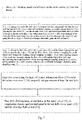
Fig. 6 is a flow chart ofStep 1 inFig. 5 ; -
Fig. 7 is a flow chart ofStep 11 inFig. 6 ; -
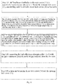
Fig. 8 is a flow chart ofStep 12 inFig. 6 ; -
Fig. 9 is a flow chart ofStep 13 inFig. 6 ; and -
Fig. 10 is a flowchart ofStep 14 inFig. 6 . - In order to solve the problem in the prior art that there is no technical solution for uncovering and recycling spent fuel assemblies, the present invention provides a spent fuel assembly uncovering and recycling system and method. The core idea of the present invention is: comprehensively consider the the inner cover weld joint, air hole cover weld joint, drainage hole cover weld joint, leakage of the thread sealing surface of the inflatable hole quick connector and the threaded sealing surface of the drainage hole quick connector, as well as the damage of the spent fuel assembly, give a safe and reliable solution for uncovering and recycling spent fuel assembly. During the short-term operation, loading, transfer and long-term storage of the spent fuel, if equipment failure, human-related events or other events cause the cladding temperature to exceed the safety benchmark, the storage tank can be safely cut to recycle the spent fuel assemblies. The spent fuel assembly uncovering and recycling system and method of the present invention can meet the requirements for the uncovering and recycling of the spent fuel assemblies in the spent fuel reprocessing plant, and realize the safe recycling of the spent fuel assemblies in the reprocessing plant, which is convenient for the safe recycling and utilization of the spent fuel assemblies in weld sealed storage tanks.
- In order to make the objects, technical solutions and advantages of the present invention clearer, the embodiments of the present invention will be further described in detail below with reference to the accompanying drawings.
- Referring to
Fig. 1 , a first embodiment of the present invention provides a spent fuel assembly uncovering and recycling system, which is suitable for a spent fuel storage tank storing a spent fuel assembly, wherein the spent fuel storage tank is a weld sealed spent fuel storage tank. The spent fuel assembly uncovering and recycling system includes: - a helium leakage and cladding
damage detection assembly 100, connected to the spentfuel storage tank 1, for controllably detecting a weld joint sealing condition of a cover assembly of the spentfuel storage tank 1 and a cladding damage condition of the spent fuel assembly in the spentfuel storage tank 1, respectively; - a water filling and exhausting assembly 200, connected to the spent
fuel storage tank 1, for controllably injecting water into the spent fuel assembly for cooling and exhausting gas in the spentfuel storage tank 1; and - a cutting
assembly 300, for controllably cutting a cover assembly weld joint of the spentfuel storage tank 1 to recycle the spent fuel assembly in the spentfuel storage tank 1. - Due to the arrangement of the helium leakage and cladding
damage detection assembly 100, the spentfuel storage tank 1 can be detected during the short-term operation, loading, transfer and long-term storage of spent fuel. Due to the arrangement of the water filling and exhausting assembly 200, the spent fuel cladding temperature can be prevented from exceeding safe benchmark, thereby improving the safety of spent fuel recycling. The welding seam of the cover assembly is cut by the cuttingassembly 300, so as to recycle the spent fuel assembly, and improve the recycle efficiency of the spent fuel assembly in the spentfuel storage tank 1. - Further, the spent fuel assembly uncovering and recycling system includes: a
control unit 400, connected to the helium leakage and claddingdamage detection assembly 100, the water filling and exhausting assembly 200 and the cuttingassembly 300 respectivelly, for controlling opening and closing of the helium leakage and claddingdamage detection assembly 100, the water filling and exhausting assembly 200 and the cuttingassembly 300, improving the controllability and automation of the spent fuel assembly uncovering and recycling system, as well as ensuring the accuracy of detection and the efficiency of recycling. - Further, as shown in
Fig. 2 , the the helium leakage and claddingdamage detection assembly 100 includes:
amain detection pipeline 140, afirst detection pipeline 150 and asecond detection pipeline 160. One end of themain detection pipeline 140 is connected to the spentfuel storage tank 1, the other end of themain detection pipeline 140 is connected to thefirst detection pipeline 150 and thesecond detection pipeline 160, resepectively. Themain detection pipeline 140, thefirst detection pipeline 150 and thesecond detection pipeline 160 are configured for transferring leaked gas from the spentfuel storage tank 1. Themain detection pipeline 140 is provided with afirst valve 110, thefirst valve 110 is connected to thecontrol unit 400 for opening and closing under the control of thecontrol unit 400. Thefirst detection pipeline 150 is provided with a heliumleakage detection module 120 for detecting helium leakage of the spentfuel storage tank 1, to detect sealing performance of the cover assembly weld joint of the spentfuel storage tank 1. Thesecond detection pipeline 160 is provided with a claddingdamage detection module 130 for sampling the leaked gas from the spentfuel storage tank 1, to detect cladding damage of the spent fuel assembly. - It should be noted that, one end of the
main detection pipeline 140 close to the spentfuel storage tank 1 is provided with a blocking cover (not shown), which is used to avoid gas leakage, and to prevent the gas from leaking into the environment, polluting the environment and causing harm to the human body. At the same time, the blocking cover can aslo improve the detection accuracy of the heliumleak detection module 120. - Further, the helium
leakage detection module 120 includes: asecond valve 121 and ahelium leakage detector 122 in communication with each other. One end of thesecond valve 121 away from thehelium leakage detector 122 is communicated with thefirst valve 110 for controlling opending and closing of thefirst detection pipeline 150. Thehelium leakage detector 122 is connected to the other end of thesecond valve 121 to detect helium leakage from the spentfuel storage tank 1 and test the sealing performance of the cover assembly weld joint of the spentfuel storage tank 1. Thecontrol unit 400 is connected to thesecond valve 121 and thehelium leakage detector 122 for controlling opening and closing of thesecond valve 121 and thehelium leakage detector 122, as well as realizing remote opening and closing of thesecond valve 121 and thehelium leakage detector 122, thereby improving the safety of the staff member. - Further, the cladding
damage detection module 130 includes athird valve 131 and a claddingdamage sampling cartridge 132 in communication with each other. One end of thethird valve 131 away from the claddingdamage sampling cartridge 132 is communicated with thefirst valve 110 to control opending and closing of the claddingdamage sampling cartridge 132. The claddingdamage sampling cartridge 132 is connected to the other end of thethird valve 131 for sampling the gas leaked from the spentfuel storage tank 1 and detecting the cladding damage of the spent fuel assembly. Thecontrol unit 400 is connected to thethird valve 131 and the claddingdamage sampling cartridge 132, to control opening and closing of thethird valve 131 and the claddingdamage sampling cartridge 132. - Further, the cladding
damage detection module 130 includes: afourth valve 133, aquick connector 134, afifth valve 138 and a highefficiency adsorption filter 135. Thefourth valve 133 and thequick connector 134 are sequentially connected between thethird valve 131 and the claddingdamage sampling cartridge 132, to control quick disconnection of the claddingdamage sampling cartridge 132 after sampling. Thefifth valve 138 is connected between the claddingdamage sampling cartridge 132 and the highefficiency adsorption filter 135, to control a flow of gas in the claddingdamage sampling cartridge 132. The highefficiency adsorption filter 135 is configured for connecting with one end of thequick connector 134 afar from thefourth valve 133 after the claddingdamage sampling cartridge 132 detects that the spent fuel assembly cladding is damaged, to purify gas leaked from the test hole. In this manner, thequick connector 134 is first connected with the claddingdamage sampling cartridge 132, for sampling the gas in the test hole and detecting the shadding. After shadding damage is detected, thequick connector 134 turns to connect with the highefficiency adsorption filter 135. In addition, thecontrol unit 400 is connected with thefourth valve 133, thequick connector 134, thefifth valve 138 and the highefficiency adsorption filter 135, for controlling opening and closing of thefourth valve 133, thequick connector 134, thefifth valve 138 and the highefficiency adsorption filter 135. - Further, the cladding
damage detection module 130 includes avacuum pump 136, apressure detector 137 and afifth valve 138. Thevacuum pump 136 is connected between the claddingdamage sampling cartridge 132 and the highefficiency adsorption filter 135, for sampling gas in thesecond detection pipeline 160. Thepressure detector 137 is connected between thethird valve 131 and thefourth valve 133, for detecting whether thesecond detection pipeline 160 is under negative pressure. If thesecond detection pipeline 160 is under negative pressure, the gas in the test hole can enter the claddingdamage sampling cartridge 132 smoothly. If theecond detection pipeline 160 is not under negative pressure, the gas in the test hole cannot enter the claddingdamage sampling cartridge 132 smoothly. Due to the arrangement of the vacuum pump, the gas in the test hole can automatically enter the claddingdamage sampling cartridge 132, thereby reducing manual operation and improving the automation level. Further, thecontrol unit 400 is connected with thevacuum pump 136 and thepressure detector 137, for controlling opening and closing of thevacuum pump 136 and thepressure detector 137, to further improve the automation level of the recycling system. - It should be noted that, the
pressure detector 137 may include afirst pressure detector 1371 and asecond pressure detector 1372 connected in parallel. By arranging two pressure detectors, the reliability of the pressure monitor 137 can be improved, to avoid inaccurate judgment of the operator due to the damage of the instruments. - In the first embodiment of the presnet invention, after the
main detection pipeline 140 is connected with the spentfuel storage tank 1 , industrial adhesives or other adhesive materials are used to temporarily block themain detection pipeline 140, to improve the connection stability between themain detection pipeline 140 and the spentfuel storage tank 1 and ensure the reliability and accuracy of the test results. - Further, referring to
Figs. 3 and 4 , the water filling and exhausting assembly 200 includes awater filling module 210 andexhausting module 220. Thewater filling module 210 includes awater pump 211 and asixth valve 212. Two ends of thesixth valve 212 are respectively connected to thewater pump 211 is communicated with the drainage holequick connector 15 of the spentfuel storage tank 1. One end of thewater pump 211 away from thesixth valve 212 is communicated with the boron-containing water source for injecting boron-containing water into the spentfuel storage tank 1. Thecontrol unit 400 is connected to thewater pump 211 and thesixth valve 212, to control the opening and closing of thewater pump 211 and thesixth valve 212. It should be noted that, a seventh valve can also be set between thewater pump 211 and thesixth valve 212 for backup. When thesixth valve 212 is unavailable, the seventh valve is activated, to improve the applicability and reliability of thewater filling module 210. - Further, the
exhausting module 220 includes acondensation tank 221 and asuction pipeline valve 222. Thecondensation tank 221 is communicated with the inflatable holequick connector 16 of the spentfuel storage tank 1 through thesuction pipeline valve 222, so that the boron-containing water in the spentfuel storage tank 1 can be heated and flashed into water vapor, and be discharged quickly from the inflatable holequick connector 16 and further be condensed through thecondensation tank 221. - In the present embodiment, the
exhausting module 220 further includes a firstexhaust pipeline valvec 223 and a secondexhaust pipeline valve 224. The firstexhaust pipeline valve 223 communicates with the top of thecondensation tank 221, and the secondexhaust pipeline valv 224 communicates with the bottom of thecondensation tank 221. The water vapor discharged from the inflatable holequick connector 16 enters thecondensation tank 221 through thesuction pipeline valve 222, and is condensed and converted into water vapor. Part of the water vapor is discharged from the top of thecondensation tank 221 via the firstexhaust pipeline valve 223. Part of the water vapor is discharged from is discharged from the bottom of the condensation tank via the secondexhaust pipeline valve 224. Thecontrol unit 400 is connected with thecondensation tank 221, thesuction pipeline valve 222, the firstexhaust pipeline valve 223 and the secondexhaust pipeline valve 224 for controlling the opening and closing of thecondensation tank 221, thesuction pipeline valve 222, the firstexhaust pipeline valve 223 and the secondexhaust pipeline valve 224. - Due to the arrangement of the
water filling module 210, the problem of exceeding the safe temperature due to high temperature caused by the spent fuel assembly loaded inside the spentfuel storage tank 1 can be reduced. Due to the arrangement of theexhausting module 220, the problem of excessively high air pressure in the spentfuel storage tank 1 is further avoided, thereby further ensuring the stability and safety of the spentfuel storage tank 1. - It should be further noted that, the cutting
assembly 300 may include a cutting unit and a hoisting unit (not shown), wherein the cutting unit is used to cut the welding seam of the cover assembly, and the hoisting unit is used to remove the cut structure after the cutting unit completes the cutting. The structures of the cutting unit and the hoisting unit are basically the same as those of the known cutting unit and the hoisting unit, and the specific structures are not repeated here. - The present invention provides a spent fuel assembly uncovering and recycling method for the spent fuel assembly uncovering and recycling system of the first embodiment of the present invention, which is suitable for a spent
fuel storage tank 1 storing spent fuel assemblies. As shown inFig. 4 , the spentfuel storage tank 1 includes : anouter cover 11, aninner cover 12, adrainage hole cover 13, anair hole cover 14, a drainage holequick connector 15, an inflatable holequick connector 16 and acylinder 17, and thecylinder 17 is installed with spent fuel assemblies. Theouter cover 11 and theinner cover 12 are welded with thecylinder 17 to form an outer cover weld and an inner cover weld. Thedrainage hole cover 13 and theair hole cover 14 are welded to theinner cover 11, to form the welding seam of theair hole cover 14 and the welding seam of thedrainage hole cover 13. The drainage holequick connector 15 and the inflatable holequick connector 16 are respectively screwed with the drain pipe and the inflatable pipe, to form the air hole quick joint thread sealing surface and the drainage hole quick connector thread sealing surface. - As shown in
Fig. 5 , the spent fuel assembly uncovering and recycling method includes the following steps: - Step 1: detecting a weld joint sealing condition of a cover assembly of a spent
fuel storage tank 1 and a cladding damage condition of the spent fuel assembly in the spentfuel storage tank 1, and purifying the leaked gas; - Step 2: connecting the purified spent
fuel storage tank 1 with awater filling module 210 and anexhausting module 220, to inject water to the spent fuel assembly for cooling and discharge gas from the spentfuel storage tank 1; and - Step 3: cutting weld joints of an
outer cover 11 and aninner cover 12 in sequence, removing theouter cover 11 and theinner cover 12, and recycling the spent fuel assembly in the spentfuel storage tank 1. - The present embodiment comprehensively considers the sealing surfaces of various layers that may affect the sealing integrity of the storage equipment during the recycling process, and considers the impact of the dangerous fission gas released by the damaged cladding of the spent fuel assembly on the human body, to meet the requirements for the recycling and utilization of spent fuel assemblies, the safe recovery of spent fuel assemblies in the reprocessing plant is realized, which is convenient for the safe recycling and utilization of spent fuel assemblies inside the storage tanks.
- Further, as shown in
Fig. 6 ,Step 1 includes: - Step 11: detecting leakage of the weld joint of the
inner cover 12, theair hole cover 13 or thedrainage hole cover 14, and cutting and removing theair hole cover 13 and drainage holecover hole cover 14 if there is leakage, otherwise, going directly to Step 12; - Step 12: detecting leakage of the inflatable hole
quick connector 16 and cutting and removing theair hole cover 13 and thedrainage hole cover 14 if there is a leakage; otherwise, going directly to Step 13; - Step 13: detecting leakage of the drainage hole
quick connector 15, and cutting and removing thedrainage hole cover 13 and theair hole cover 14 if there is a leakage; otherwise, going directly to Step 14; and - Step 14: detecting damage of the spent fuel assembly cladding and purifying the gas leaked after the damage if there is a leakage; otherwise, going directly to Step S2. Via detecting the damage of the spent fuel assembly cladding, the harmful gas after damage is prevented from entering the environment and further harming the environment and human body.
- Further, referring to
Fig. 7 ,Step 11 may further include: - Step 111: drilling small-sized holes on the
outer cover 11 as test holes. The small-sized holes can meet the requirements of the test and cannot destroy the overall structure. - Step 112: placing one end of the first valve (110) in the test hole, temporarily blocking the test hole via industrial adhesives or other glue materials; starting the
helium leakage detector 122, opening thefirst valve 110 and thesecond valve 121, and detecting whether there is helium in the gas in the test hole through thehelium leak detector 122, to detect the leakage of the weld joint of theinner cover 12, theair hole cover 13 or thedrainage hole cover 14 and going directly to Step 113 if there is a leakage; otherwise, going directly to Step 12. The use of the industrial adhesives or other glue materials for temporary bloking can further ensure the reliability and accuracy of the test. - Step 113: closing the
first valve 110, thesecond valve 121 and thehelium leakage detector 122, opening thethird valve 131 and thefirst valve 110 in sequence, sampling the gas in the test hole through the claddingdamage sampling cartridge 132 to detect cladding damage of the spent fuel assembly; closing thefirst valve 110 and thethird valve 131, and disconnecting the connection between the claddingdamage sampling cartridge 132 and thequick connector 134 after sampling; going to step 114 if there is damage; otherwise, going directly to step 115; - Step 114: connecting the high
efficiency adsorption filter 135 with thequick connector 134, to purify the gas extracted from the test hole; - Step 115: drilling large-sized holes on the
outer cover 11 to completely expose and cut and remove the airhole cover plate 14 and thedrainage hole cover 13. With this arrangement, before cutting and removing theair hole cover 14 and thedrainage hole cover 13, first drill holes in the inflatable hole position and the drainage hole position of theouter cover 11 of the fuel storage tank, so that theair hole cover 14 and thedrainage hole cover 13 is easy to cut and remove, so as to prevent other structures from being affected. - Further, referring to
Fig. 8 ,Step 12 may further include: - Step 121: drilling small-sized holes on the
outer cover 11, and drilling holes onair hole cover 14 as test holes; - Step 122: placing one end of the
first valve 110 in the test hole, and temporarily blocking the test hole via industrial adhesives or other glue materials; starting thehelium leakage detector 122, opening thefirst valve 110 and thesecond valve 121; detecting whether there is helium in the gas in the test hole through thehelium leakage detector 122, to determine the leakage of the inflatable holequick connector 16; if there is leakage, going to Step 123; otherwise, going directly to Step 13; - Step 123: closing the
first valve 110, thesecond valve 121 and thehelium leakage detector 122, opening thethird valve 131 and thefirst valve 110 in sequence, sampling the gas in the test hole through the claddingdamage sampling cartridge 132 to detect the damage of the spent fuel cladding; after sampling, closing thefirst valve 110 and thethird valve 131, and disconnecting the connection between the claddingdamage sampling cartridge 132 and thequick connector 134; if there is damage, going to step 124; otherwise, going directly to step 125; - Step 124: connecting the high
efficiency adsorption filter 135 with thequick connector 134 to purify the gas extracted from the test hole; and - Step 125: cutting and removing the
air hole cover 14 and thedrainage hole cover 13. - Further, referring to
Fig. 9 , step 13 may further include: - Step 131: drilling holes on the
drainage hole cover 13 as a test hole; - Step 132: placing one end of the
first valve 110 in the test hole, and temporarily blocking the test hole via industrial adhesives or other adhesive materials; starting thehelium leakage detector 122, opening the first valve and thesecond valve 121, and detecting whether there is helium in the gas in the test hole through thehelium leakage detector 122, to determine the leakage of the drainage holequick connector 15; if there is leakage, going to Step 133; otherwise, going directly to Step 14; - Step 133: closing the
first valve 110, thesecond valve 121 and thehelium leakage detector 122, opening thethird valve 131 and thefirst valve 110 in sequence, sampling the gas in the test hole through the claddingdamage sampling cartridge 132 to detect the damage of the spent fuel cladding; after sampling, closing thefirst valve 110 and thethird valve 131, and disconnecting the connection between the claddingdamage sampling cartridge 132 and thequick connector 134; if there is damage, going to Step 134; otherwise, going directly to Step 135; - Step 134: connecting the high
efficiency adsorption filter 135 with thequick connector 134 to purify the gas extracted from the test hole; and - Step 135: cutting and removing the
air hole cover 14 and thedrainage hole cover 13. - Further, referring to
Fig. 10 ,Step 14 may further include: - Step 141: using the inflatable hole
quick connector 16 as the test hole; - Step 142: placing one end of the
first valve 110 in the test hole; opening thethird valve 131 and thefirst valve 121 in sequence, and sampling the gas in the test hole through the claddingdamage sampling cartridge 132, to detect the damage of the spent fuel cladding; after sampling, closing thefirst valve 110 and thethird valve 131, and disconnecting the connection between the claddingdamage sampling cartridge 132 and thequick connector 134; if there is damage, going to Step 143; otherwise, going directly toStep 2; and - Step 143: connecting the high
efficiency adsorption filter 135 with thequick connector 134 to purify the gas extracted from the test hole. If there is no leakage in the spentfuel storage tank 1, detecting the damage of the spent fuel assembly cladding can improve the safety of the spent fuel assembly recycling and avoid human events. - Specifically,
Step 2 includes: connecting thewater filling module 210 with the drainage holequick connector 15 to ineject boron-containing water into the spentfuel storage tank 1; connecting theexhausting module 220 with the inflatable holequick connector 16, to make the boron-containing water in the spentfuel storage tank 1 heated and flashed into water vapor and further condensed and discharged from the inflatable holequick connector 16, thereby avoiding accidents cased by the temperature of the spent fuel assembly exceeding the safety benchmark. - It should be noted that, before performing the above steps, it is first necessary to confirm that the
first valve 110, thesecond valve 121, thethird valve 131, thefourth valve 133 and thefifth valve 138 are in a closed state. - Summarizing the above, the present invention comprehensively considers the the inner cover weld joint, air hole cover weld joint, drainage hole cover weld joint, leakage of the thread sealing surface of the inflatable hole quick connector and the threaded sealing surface of the drainage hole quick connector, as well as the damage of the spent fuel assembly, give a safe and reliable solution for uncovering and recycling spent fuel assembly. During the short-term operation, loading, transfer and long-term storage of the spent fuel, if equipment failure, human-related events or other events cause the cladding temperature to exceed the safety benchmark, the storage tank can be safely cut to recycle the spent fuel assemblies. The spent fuel assembly uncovering and recycling system and method of the present invention can meet the requirements for the uncovering and recycling of the spent fuel assemblies in the spent fuel reprocessing plant, and realize the safe recycling of the spent fuel assemblies in the reprocessing plant, which is convenient for the safe recycling and utilization of the spent fuel assemblies in weld sealed storage tanks.
- The above described embodiments are only preferred embodiments of the present invention, and are not intended to limit the scope of the present invention. Any modification, equivalent replacement and improvement within the spirit and principle of the present invention should be included in the protection scope of the present invention.
Claims (18)
- A spent fuel assembly uncovering and recycling system, suitable for a spent fuel storage tank (1) storing a spent fuel assembly, characterized in that, the spent fuel assembly uncovering and recycling system comprises:a helium leakage and cladding damage detection assembly (100), connected to the spent fuel storage tank (1), for controllably detecting a weld joint sealing condition of a cover assembly of the spent fuel storage tank (1) and a cladding damage condition of the spent fuel assembly in the spent fuel storage tank (1), respectively;a water filling and exhausting assembly (200), connected to the spent fuel storage tank (1), for controllably injecting water into the spent fuel assembly for cooling and exhausting gas in the spent fuel storage tank (1); anda cutting assembly (300), for controllably cutting a cover assembly weld joint of the spent fuel storage tank (1) to recycle the spent fuel assembly in the spent fuel storage tank (1).
- The spent fuel assembly uncovering and recycling system according to claim 1, characterized in that, the spent fuel assembly uncovering and recycling system further comprises: a control unit (400), connected to the helium leakage and cladding damage detection assembly (100), the water filling and exhausting assembly (200) and the cutting assembly (300) respectivelly, for controlling opening and closing of the helium leakage and cladding damage detection assembly (100), the water filling and exhausting assembly (200) and the cutting assembly (300).
- The spent fuel assembly uncovering and recycling system according to claim 2, characterized in that, the helium leakage and cladding damage detection assembly (100) comprises a main detection pipeline (140), a first detection pipeline (150) and a second detection pipeline (160), one end of the main detection pipeline (140) is connected to the spent fuel storage tank (1), the other end of the main detection pipeline (140) is connected to the first detection pipeline (150) and the second detection pipeline (160), resepectively, the main detection pipeline (140), the first detection pipeline (150) and the second detection pipeline (160) are configured for transferring leaked gas from the spent fuel storage tank ( 1);
the main detection pipeline (140) is provided with a first valve (110), the first valve (110) is connected to the control unit (400) for opening and closing under the control of the control unit (400); the first detection pipeline (150) is provided with a helium leakage detection module (120) for detecting helium leakage of the spent fuel storage tank (1), to detect sealing performance of the cover assembly weld joint of the spent fuel storage tank (1); the second detection pipeline (160) is provided with a cladding damage detection module (130) for sampling the leaked gas from the spent fuel storage tank (1), to detect cladding damage of the spent fuel assembly. - The spent fuel assembly uncovering and recycling system according to claim 3, characterized in that, one end of the main detection pipeline (140) close to the spent fuel storage tank (1) is provided with a blocking cover.
- The spent fuel assembly uncovering and recycling system according to claim 4, characterized in that, the helium leakage detection module (120) comprises: a second valve (121) and a helium leakage detector (122) in communication with each other; one end of the second valve (121) is communicated with the first valve (110) for controlling opending and closing of the first detection pipeline (150); the helium leakage detector (122) is connected to the other end of the second valve (121) to detect helium leakage from the spent fuel storage tank (1) and test the sealing performance of the cover assembly weld joint of the spent fuel storage tank (1); the control unit (400) is connected to the second valve (121) and the helium leakage detector (122) for controlling opening and closing of the second valve (121) and the helium leakage detector (122).
- The spent fuel assembly uncovering and recycling system according to claim 5, characterized in that, the cladding damage detection module (130) comprises a third valve (131) and a cladding damage sampling cartridge (132) in communication with each other, one end of the third valve (131) is communicated with the first valve (110) to control opending and closing of the second detection pipeline (160); the cladding damage sampling cartridge (132) is connected to the other end of the third valve (131) for sampling the gas leaked from the spent fuel storage tank (1) and detecting the cladding damage of the spent fuel assembly; the control unit (400) is connected to the third valve ( 131 ) and the cladding damage sampling cartridge (132), to control opening and closing of the third valve (131) and the cladding damage sampling cartridge (132).
- The spent fuel assembly uncovering and recycling system according to claim 6, characterized in that, the cladding damage detection module (130) further comprises: a fourth valve (133), a quick connector (134), a fifth valve (138) and a high efficiency adsorption filter (135);the fourth valve (133) and the quick connector (134) are sequentially connected between the third valve (131) and the cladding damage sampling cartridge (132), to control quick disconnection of the cladding damage sampling cartridge (132) after sampling;the fifth valve (138) is connected between the cladding damage sampling cartridge (132) and the high efficiency adsorption filter (135), to control a flow of gas in the cladding damage sampling cartridge (132);the high efficiency adsorption filter (135) is configured for connecting with one end of the quick connector (134) afar from the fourth valve (133) after the cladding damage sampling cartridge (132) detects that the spent fuel shadding is damaged, to purify gas leaked from the spent fuel storage tank (1); andthe control unit (400) is connected with the fourth valve (133), the quick connector (134), the fifth valve (138) and the high efficiency adsorption filter (135), for controlling opening and closing of the fourth valve (133), the quick connector (134), the fifth valve (138) and the high efficiency adsorption filter (135).
- The spent fuel assembly uncovering and recycling system according to claim 7, characterized in that, the cladding damage detection module (130) further comprises a vacuum pump (136) and a pressure detector (137),the vacuum pump (136) is connected between the cladding damage sampling cartridge (132) and the high efficiency adsorption filter (135), for sampling gas in the second detection pipeline (160);the pressure detector (137) is connected between the third valve (131) and the fourth valve (133), for detecting a pressure state of the second detection pipeline (160); andthe control unit (400) is connected with the vacuum pump (136) and the pressure detector (137), for controlling opening and closing of the vacuum pump (136) and the pressure detector (137).
- The spent fuel assembly uncovering and recycling system according to claim 2, characterized in that, the water filling and exhausting assembly (200) comprises a water filling module (210) and an exhausting module (220), the water filling module (210) is connected to the spent fuel storage tank (1) to inject boron-containing water into the spent fuel storage tank (1); the exhausting module (220) is connected to the spent fuel storage tank (1), to make the boron-containing water in the spent fuel storage tank (1) flash evaporated into water vapor after being heated to be exhausted.
- The spent fuel assembly uncovering and recycling system according to claim 9, characterized in that, the water filling module (210) comprises a water pump (211) and a sixth valve (212); two ends of the sixth valve (212) ) are respectively communicated with the water pump (211) and the drainage hole quick connector (15); one end of the water pump (211) afar from the sixth valve (212) is communicated with the boron-containing water source to inject boron-containing water into the spent fuel storage tank (1); the control unit (400) is connected to the water pump (211) and the sixth valve (212), to control opening and closing the of the water pump (211) and the sixth valve (212).
- The spent fuel assembly uncovering and recycling system according to claim 10, characterized in that, the exhausting module (220) comprises a condensation tank (221), a suction pipeline valve (222), a first exhaust pipeline valve (223) and a second exhaust pipeline valve (224); the first exhaust pipeline valve (223) communicates with a top of the condensation tank (221), the second exhaust pipeline valve (224) communicates with a bottom of the condensation tank tank (221), and the condensation tank (221) is communicated with an inflatable hole quick connector (16) through the suction pipeline valve (222), so that the boron-containing water in the spent fuel storage tank (1) is heated and flashed into water vapor and further discharged to the condensation tank (221), and part of the water vapor condensed by the condensation tank (221) is discharged from the top of the condensation tank (221) through the first exhaust pipeline valve (223), and the other part of the water vapor condensed by the condensation tank (221) is discharged from the bottom of the condensation tank (221) through the second exhaust pipeline valve (224); the control unit (400) is connected with the condensation tank (221), the suction pipeline valve (222), the first exhaust pipeline valve (223) and the second exhaust pipeline valve (224) for controlling opening and closing of the condensation tank (221), the suction pipeline valve (222), the first exhaust pipeline valve (223) and the second exhaust pipeline valve (224).
- A spent fuel assembly uncovering and recycling method, comprising the steps of:Step 1: detecting a weld joint sealing condition of a cover assembly of a spent fuel storage tank (1) and a cladding damage condition of the spent fuel assembly in the spent fuel storage tank (1), and purifying the leaked gas;Step 2: connecting the purified spent fuel storage tank (1) with a water filling module (210) and an exhausting module (220), to inject water to the spent fuel assembly for cooling and discharge gas from the spent fuel storage tank (1); andStep 3: cutting weld joints of an outer cover (11) and an inner cover (12) in sequence, removing the outer cover (11) and the inner cover (12), and recycling the spent fuel assembly in the spent fuel storage tank (1).
- The spent fuel assembly uncovering and recycling method according to claim 12, characterized in that, Step 1 comprises the steps of:Step 11: detecting leakage of the weld joint of the inner cover (12), the air hole cover (13) or the drainage hole cover (14), and cutting and removing the air hole cover (13) and drainage hole cover hole cover (14) if there is leakage, otherwise, going directly to Step 12;Step 12: detecting leakage of the inflatable hole quick connector (16) and cutting and removing the air hole cover (13) and the drainage hole cover (14) if there is a leakage; otherwise, going directly to Step 13;Step 13: detecting leakage of the drainage hole quick connector (15), and cutting and removing the drainage hole cover (13) and the air hole cover (14) if there is a leakage; otherwise, going directly to Step 14; andStep 14: detecting damage of the spent fuel assembly cladding and purifying the gas leaked after the damage if there is a leakage; otherwise, going directly to Step S2.
- The spent fuel assembly uncovering and recycling method according to claim 13, characterized in that, Step 11 comprises:Step 111: drilling small-sized holes on the outer cover (11) as test holes;Step 112: placing one end of the first valve (110) in the test hole, temporarily blocking the test hole via industrial adhesives or other glue materials; starting the helium leakage detector (122), opening the first valve (110) and the second valve (121), and detecting whether there is helium in the gas in the test hole through the helium leak detector (122), to detect the leakage of the weld joint of the inner cover (12), the air hole cover (13) or the drainage hole cover (14) and going directly to Step 113 if there is a leakage; otherwise, going directly to Step 12;Step 113: closing the first valve (110), the second valve (121) and the helium leakage detector (122), opening the third valve (131) and the first valve (110) in sequence, sampling the gas in the test hole through the cladding damage sampling cartridge (132) to detect cladding damage of the spent fuel assembly; closing the first valve (110) and the third valve (131), and disconnecting the connection between the cladding damage sampling cartridge (132) and the quick connector (134) after sampling; going to step 114 if there is damage; otherwise, going directly to step 115;Step 114: connecting the high efficiency adsorption filter (135) with the quick connector (134), to purify the gas extracted from the test hole;Step 115: drilling large-sized holes on the outer cover (11) to completely expose and cut and remove the air hole cover plate (14) and the drainage hole cover (13).
- The spent fuel assembly uncovering and recycling method according to claim 14, characterized in that, Step 12 comprises:Step 121: drilling large-sized holes on the outer cover (11) to completely expose the air hole cover (14) and the drainage hole cover (13), and drilling small-sized holes on air hole cover (14) as test holes;Step 122: placing one end of the first valve (110) in the test hole, and temporarily blocking the test hole via industrial adhesives or other glue materials; starting the helium leakage detector (122), opening the first valve (110) and the second valve (121); detecting whether there is helium in the gas in the test hole through the helium leakage detector (122), to determine the leakage of the inflatable hole quick connector (16); if there is leakage, going to Step 123; otherwise, going directly to Step 13;Step 123: closing the first valve (110), the second valve (121) and the helium leakage detector (122), opening the third valve (131) and the first valve (110) in sequence, sampling the gas in the test hole through the cladding damage sampling cartridge (132) to detect the damage of the spent fuel cladding; after sampling, closing the first valve (110) and the third valve (131), and disconnecting the connection between the cladding damage sampling cartridge (132) and the quick connector (134); if there is damage, going to step 124; otherwise, going directly to step 125;Step 124: connecting the high efficiency adsorption filter (135) with the quick connector (134) to purify the gas extracted from the test hole; andStep 125: cutting and removing the air hole cover (14) and the drainage hole cover (13).
- The spent fuel assembly uncovering and recycling method according to claim 15, characterized in that, Step 13 comprises:Step 131: drilling holes on the drainage hole cover (13) as a test hole;Step 132: placing one end of the first valve (110) in the test hole, and temporarily blocking the test hole via industrial adhesives or other adhesive materials; starting the helium leakage detector (122), opening the first valve and the second valve (121), and detecting whether there is helium in the gas in the test hole through the helium leakage detector (122), to determine the leakage of the drainage hole quick connector (15); if there is leakage, going to Step 133; otherwise, going directly to Step 14;Step 133: closing the first valve (110), the second valve (121) and the helium leakage detector (122), opening the third valve (131) and the first valve (110) in sequence, sampling the gas in the test hole through the cladding damage sampling cartridge (132) to detect the damage of the spent fuel cladding; after sampling, closing the first valve (110) and the third valve (131), and disconnecting the connection between the cladding damage sampling cartridge (132) and the quick connector (134); if there is damage, going to Step 134; otherwise, going directly to Step 135;Step 134: connecting the high efficiency adsorption filter (135) with the quick connector (134) to purify the gas extracted from the test hole; andStep 135: cutting and removing the air hole cover (14) and the drainage hole cover (13).
- The spent fuel assembly uncovering and recycling method according to claim 16, characterized in that, Step 14 comprises:Step 141: using the inflatable hole quick connector (16) as the test hole;Step 142: placing one end of the first valve (110) in the test hole; opening the third valve (131) and the first valve (121) in sequence, and sampling the gas in the test hole through the cladding damage sampling cartridge (132), to detect the damage of the spent fuel cladding; after sampling, closing the first valve (110) and the third valve (131), and disconnecting the connection between the cladding damage sampling cartridge (132) and the quick connector (134); if there is damage, going to Step 143; otherwise, going directly to Step 2; andStep 143: connecting the high efficiency adsorption filter (135) with the quick connector (134) to purify the gas extracted from the test hole.
- The spent fuel assembly uncovering and recycling method according to claim 13, characterized in that, Step 2 comprising: connecting the water filling module (210) with the drainage hole quick connector (15) to ineject boron-containing water into the spent fuel storage tank (1); connecting the exhausting module (220) with the inflatable hole quick connector (16), to make the boron-containing water in the spent fuel storage tank (1) heated and flashed into water vapor and further condensed and discharged from the inflatable hole quick connector (16)..
Applications Claiming Priority (2)
| Application Number | Priority Date | Filing Date | Title |
|---|---|---|---|
| CN201910869206.0A CN110619966B (en) | 2019-09-16 | 2019-09-16 | A system and method for uncovering and retrieving spent fuel assemblies |
| PCT/CN2019/122418 WO2021051659A1 (en) | 2019-09-16 | 2019-12-02 | Spent fuel assembly uncovering and recycling system and method |
Publications (2)
| Publication Number | Publication Date |
|---|---|
| EP4044198A1 true EP4044198A1 (en) | 2022-08-17 |
| EP4044198A4 EP4044198A4 (en) | 2023-11-29 |
Family
ID=68922824
Family Applications (1)
| Application Number | Title | Priority Date | Filing Date |
|---|---|---|---|
| EP19945629.4A Pending EP4044198A4 (en) | 2019-09-16 | 2019-12-02 | Spent fuel assembly uncovering and recycling system and method |
Country Status (3)
| Country | Link |
|---|---|
| EP (1) | EP4044198A4 (en) |
| CN (1) | CN110619966B (en) |
| WO (1) | WO2021051659A1 (en) |
Families Citing this family (3)
| Publication number | Priority date | Publication date | Assignee | Title |
|---|---|---|---|---|
| CN114188060B (en) * | 2021-10-27 | 2025-03-14 | 中国原子能科学研究院 | A sealing welding treatment method for damaged spent fuel assembly |
| CN115171935B (en) * | 2022-07-29 | 2025-02-18 | 华能核能技术研究院有限公司 | Automatic loading system and method for new fuel of pebble bed high temperature reactor |
| CN120260997B (en) * | 2025-04-03 | 2025-09-30 | 中核四0四有限公司 | Underwater collection and storage device for damaged pipe section of spent fuel assembly |
Family Cites Families (12)
| Publication number | Priority date | Publication date | Assignee | Title |
|---|---|---|---|---|
| FR2081176A1 (en) * | 1970-03-13 | 1971-12-03 | Commissariat Energie Atomique | Extraction of irradiated fuel elements - for recovery of fissile material and fission products |
| JPH08292287A (en) * | 1995-04-21 | 1996-11-05 | Hitachi Ltd | How to monitor spent fuel storage |
| US5862195A (en) * | 1996-09-09 | 1999-01-19 | Peterson, Ii; William Donald | Canister, transport, storage, monitoring, and retrieval system |
| GB9815421D0 (en) * | 1998-07-16 | 1998-09-16 | British Nuclear Fuels Plc | Fuel containment apparatus |
| JP2003156593A (en) * | 2001-11-21 | 2003-05-30 | Toshiba Corp | Underwater laser cutter of radioactive long load |
| JP2015004662A (en) * | 2013-05-21 | 2015-01-08 | 日立化成株式会社 | Molten fuel retrieval device |
| CN204964148U (en) * | 2015-07-30 | 2016-01-13 | 苏州热工研究院有限公司 | Irradiated fuel assembly breakage detection device |
| WO2017087106A2 (en) * | 2015-10-16 | 2017-05-26 | Holtec International | Nuclear waste storage canisters |
| CN105931691B (en) * | 2016-04-21 | 2018-01-12 | 中广核核电运营有限公司 | Nuclear Power Station's Exhausted Fuels radgas processing method |
| CN106504804A (en) * | 2016-12-30 | 2017-03-15 | 核动力运行研究所 | A kind of cooling system and method for spent fuel transport container in discharge process |
| CN209357469U (en) * | 2018-08-20 | 2019-09-06 | 深圳中广核工程设计有限公司 | Nuclear power station ventilating hole channel structure and spentnuclear fuel Dry storage device |
| CN109599198B (en) * | 2018-12-12 | 2020-09-25 | 深圳中广核工程设计有限公司 | Spent fuel storage tank for nuclear power plant |
-
2019
- 2019-09-16 CN CN201910869206.0A patent/CN110619966B/en active Active
- 2019-12-02 WO PCT/CN2019/122418 patent/WO2021051659A1/en not_active Ceased
- 2019-12-02 EP EP19945629.4A patent/EP4044198A4/en active Pending
Also Published As
| Publication number | Publication date |
|---|---|
| EP4044198A4 (en) | 2023-11-29 |
| WO2021051659A1 (en) | 2021-03-25 |
| CN110619966A (en) | 2019-12-27 |
| CN110619966B (en) | 2021-09-07 |
Similar Documents
| Publication | Publication Date | Title |
|---|---|---|
| CN110619966A (en) | Spent fuel assembly uncovering and retrieving system and method | |
| US11646123B2 (en) | Three-way valve operational to both transfer steam to a decontamination water tank under one accident situation and discharge the steam to atmosphere under a different accident situation | |
| CN111681794B (en) | Full-range SGTR accident handling method and system for pressurized water reactor nuclear power plant | |
| KR101495784B1 (en) | Device for collecting and leak detecting of gas pipeline | |
| JP7285201B2 (en) | Hydrogen treatment system | |
| US4081323A (en) | Subatmospheric double containment system | |
| CN106448783A (en) | Dual-functional spent-fuel storage and transportation metal tank of nuclear power plant | |
| JP2010539507A (en) | Method for filling the primary primary cooling system of a nuclear power plant with water and exhausting air from the system, and head for carrying out this method | |
| CN203839051U (en) | Passive filter discharge system for underground nuclear power plants | |
| CN104681107A (en) | System and method for preventing inner shell failure and radioactive release of dual-layer containment | |
| CN105845187A (en) | Severe nuclear power plant accident mitigating system | |
| CN108447575B (en) | Dry storage and loading method of pressurized water reactor spent fuel | |
| CN205751540U (en) | Major accident mitigation system of nuclear | |
| CN111156423B (en) | Active safety protection system and method for hydrogen leakage | |
| CN105605364B (en) | Sealing jig for pipe fittings and sealing method for pipe fittings | |
| JP5173834B2 (en) | Method and apparatus for sealing a canister loaded with spent nuclear fuel in a cooling bath | |
| CN117945496A (en) | Method and device for removing residual tritium from filter core of waste filter in heavy water pile disposal pit | |
| CN107719888A (en) | A kind of radioactive liquid waste transporter | |
| CN206259183U (en) | A kind of Nuclear Power Station's Exhausted Fuels component level storage fuel tank | |
| CN102519681A (en) | Detection method for quality of welding line of sealed container | |
| CN117594255A (en) | Pressure relief and discharge device to seawater in case of serious accident of marine floating nuclear power plant | |
| CN219043328U (en) | Sealing shielding system for gaseous Po-210 test | |
| CN110600151A (en) | Laboratory support system suitable for contain tritium helium gas return circuit | |
| CN102444759B (en) | Composite multi-pipeline tee joint structure assembly | |
| CN115331858B (en) | SGTR accident handling method and control system for pressurized water reactor nuclear power plant |
Legal Events
| Date | Code | Title | Description |
|---|---|---|---|
| STAA | Information on the status of an ep patent application or granted ep patent |
Free format text: STATUS: THE INTERNATIONAL PUBLICATION HAS BEEN MADE |
|
| PUAI | Public reference made under article 153(3) epc to a published international application that has entered the european phase |
Free format text: ORIGINAL CODE: 0009012 |
|
| STAA | Information on the status of an ep patent application or granted ep patent |
Free format text: STATUS: REQUEST FOR EXAMINATION WAS MADE |
|
| 17P | Request for examination filed |
Effective date: 20220414 |
|
| AK | Designated contracting states |
Kind code of ref document: A1 Designated state(s): AL AT BE BG CH CY CZ DE DK EE ES FI FR GB GR HR HU IE IS IT LI LT LU LV MC MK MT NL NO PL PT RO RS SE SI SK SM TR |
|
| DAV | Request for validation of the european patent (deleted) | ||
| DAX | Request for extension of the european patent (deleted) | ||
| REG | Reference to a national code |
Ref country code: DE Ref legal event code: R079 Free format text: PREVIOUS MAIN CLASS: G21C0019020000 Ipc: G21C0017070000 |
|
| A4 | Supplementary search report drawn up and despatched |
Effective date: 20231026 |
|
| RIC1 | Information provided on ipc code assigned before grant |
Ipc: G21F 5/12 20060101ALI20231020BHEP Ipc: G21C 19/07 20060101ALI20231020BHEP Ipc: G21F 5/14 20060101ALI20231020BHEP Ipc: G21C 17/07 20060101AFI20231020BHEP |