EP4044196A1 - Nuclear power plant personnel gate and installation method thereof - Google Patents
Nuclear power plant personnel gate and installation method thereof Download PDFInfo
- Publication number
- EP4044196A1 EP4044196A1 EP19944888.7A EP19944888A EP4044196A1 EP 4044196 A1 EP4044196 A1 EP 4044196A1 EP 19944888 A EP19944888 A EP 19944888A EP 4044196 A1 EP4044196 A1 EP 4044196A1
- Authority
- EP
- European Patent Office
- Prior art keywords
- sealing door
- power plant
- nuclear power
- personnel gate
- interlock
- Prior art date
- Legal status (The legal status is an assumption and is not a legal conclusion. Google has not performed a legal analysis and makes no representation as to the accuracy of the status listed.)
- Granted
Links
Images


Classifications
-
- G—PHYSICS
- G21—NUCLEAR PHYSICS; NUCLEAR ENGINEERING
- G21C—NUCLEAR REACTORS
- G21C13/00—Pressure vessels; Containment vessels; Containment in general
- G21C13/02—Details
-
- G—PHYSICS
- G21—NUCLEAR PHYSICS; NUCLEAR ENGINEERING
- G21C—NUCLEAR REACTORS
- G21C13/00—Pressure vessels; Containment vessels; Containment in general
- G21C13/02—Details
- G21C13/028—Seals, e.g. for pressure vessels or containment vessels
-
- G—PHYSICS
- G21—NUCLEAR PHYSICS; NUCLEAR ENGINEERING
- G21F—PROTECTION AGAINST X-RADIATION, GAMMA RADIATION, CORPUSCULAR RADIATION OR PARTICLE BOMBARDMENT; TREATING RADIOACTIVELY CONTAMINATED MATERIAL; DECONTAMINATION ARRANGEMENTS THEREFOR
- G21F7/00—Shielded cells or rooms
- G21F7/005—Shielded passages through walls; Locks; Transferring devices between rooms
-
- E—FIXED CONSTRUCTIONS
- E06—DOORS, WINDOWS, SHUTTERS, OR ROLLER BLINDS IN GENERAL; LADDERS
- E06B—FIXED OR MOVABLE CLOSURES FOR OPENINGS IN BUILDINGS, VEHICLES, FENCES OR LIKE ENCLOSURES IN GENERAL, e.g. DOORS, WINDOWS, BLINDS, GATES
- E06B5/00—Doors, windows, or like closures for special purposes; Border constructions therefor
- E06B5/10—Doors, windows, or like closures for special purposes; Border constructions therefor for protection against air-raid or other war-like action; for other protective purposes
- E06B5/18—Doors, windows, or like closures for special purposes; Border constructions therefor for protection against air-raid or other war-like action; for other protective purposes against harmful radiation
-
- Y—GENERAL TAGGING OF NEW TECHNOLOGICAL DEVELOPMENTS; GENERAL TAGGING OF CROSS-SECTIONAL TECHNOLOGIES SPANNING OVER SEVERAL SECTIONS OF THE IPC; TECHNICAL SUBJECTS COVERED BY FORMER USPC CROSS-REFERENCE ART COLLECTIONS [XRACs] AND DIGESTS
- Y02—TECHNOLOGIES OR APPLICATIONS FOR MITIGATION OR ADAPTATION AGAINST CLIMATE CHANGE
- Y02E—REDUCTION OF GREENHOUSE GAS [GHG] EMISSIONS, RELATED TO ENERGY GENERATION, TRANSMISSION OR DISTRIBUTION
- Y02E30/00—Energy generation of nuclear origin
- Y02E30/30—Nuclear fission reactors
Definitions
- the present invention generally relates to nuclear power plants, and more particularly, relates to a nuclear power plant personnel gate and installation method thereof.
- nuclear reactors are equipped with containment systems. In normal operating conditions, abnormal operating conditions and accident conditions, it is necessary to maintain the integrity and sealing of the containment pressure boundary, to prevent the leakage of radioactive materials. As an important part of the pressure boundary of the nuclear reactor containment, the nuclear power plant personnel gate also needs to undertake the same functional requirements.
- the conventional nuclear power plant personnel gates have the disadvantages of unsatisfactory sealing leakage rate, low transmission precision, and inconvenient installation process.
- One object of the present invention is to provide a nuclear power plant personnel gate and installation method thereof, to solve the technical problem that the sealing leakage rate of the conventional nuclear power plant personnel gate does not meet the requirements of actual use.
- a nuclear power plant personnel gate applicable to a double-layered containment of a nuclear power plant, the double-layered containment including an outer containment and an inner containment, the inner containment and the outer containment being correspondingly provided with an inner pre-buried penetrating piece and an outer pre-buried penetrating piece, and the personnel gate passing through the inner pre-buried penetrating piece and the outer pre-buried penetrating piece, wherein the inner pre-buried penetrating piece is fixedly connected to the personnel gate, and the outer pre-buried penetrating piece is flexibly connected to the personnel gate in a sealed mode.
- the nuclear power plant personnel gate includes: a shell ring assembly passing through and supporting the inner pre-buried penetrating piece and the outer pre-buried penetrating piece; an outer sealing door movably arranged at one side of the shell ring assembly close to the outer containment, for establishing a shielding sealing barrier on the boundary of the outer containment; an inner sealing door, movably arranged at one side of the shell ring assembly close to the inner containment, for establishing a pressure-bearing sealing barrier on the boundary of the inner containment; the shell ring assembly, the outer sealing door, and the inner sealing door jointly enclose a sealed space; and an intermediate transmission cartridge detachably disposed in the sealed space and movably connected to the inner sealing door and the outer sealing door, for controlling opening and closing of the the inner sealing door and the outer sealing door.
- the shell ring assembly includes: an inner shell ring, an outer shell ring, and an intermediate shell ring fixedly connected to the inner shell ring and the outer shell ring, the inner shell ring is connected to the inner sealing door, and the outer shell ring is connected to the outer sealing door, the inner pre-buried penetrating piece is fixedly connected to the intermediate shell ring through a cantilever connection support ring plate, to support the personnel gate to the pre-buried penetrating piece and improve the synchronization of the displacement of the double-layer containment.
- the outer pre-buried penetrating piece is flexibly and sealingly connected to the ntermediate shell ring through a displacement compensation assembly, to compensate the displacement deviation of the intermediate shell ring and the outer shell ring in the civil installation and earthquake environment, and ensure the sealing between the outer containment and the inner containment ring corridor.
- the cantilever connection support ring plate includes: a support plate body having one end fixedly connected to the intermediate shell ring and other end extending upwardly, the support plate body having a height higher than a height of the inner pre-buried penetrating piece, and the support plate body being welded and connected to the inner pre-buried penetrating piece through a circumferential weld; and a backing plate arranged below the inner pre-buried penetrating piece and fixedly connected to the support plate body.
- the displacement compensation assembly includes a first clamp and a second clamp correspondingly disposed on the intermediate shell ring and the outer pre-buried penetrating piece, and a displacement compensation body connecting the intermediate shell ring and the outer pre-buried penetrating piece, one end of the displacement compensation body is fixed on the outer pre-buried penetrating piece via the first clamp, and the other end of the displacement compensation body is fixed on the intermediate shell ring via the second clamp.
- the displacement compensation body includes multiple layers of materials, an inner layer is a reinforcing cloth with high tensile strength to improve sealing performance, an outer layer is a protective ceramic cloth to improve fire performance, and the inner layer is assembled by thermal welding at the construction site and the outer layer is assembled by stitching.
- an inner surface of the inner layer of the displacement compensation body is coated with a high temperature resistant food-grade silica gel coating, to improve the high temperature resistance performance thereof.
- the intermediate transmission cartridge has an accommodating space, a multilayer transmission assembly is movably arranged in the accommodating space, and the multilayer transmission assembly is detachably connected to the intermediate transmission cartridge; each multilayer transmission assembly is driven by gears, and the multilayer transmission assembly drives the inner sealing door and the outer sealing door, and realizes the opening of the inner sealing door and the outer sealing door by means of mechanical interlocking.
- the multilayer transmission assembly includes: a power source module, a drive and pressure balance module and an interlocking mechanism module; the power source module is arranged at a bottom of the intermediate transmission cartridge to generate driving power manually or electrically; an input end of the drive and pressure balance module is connected to the power source module, and an output end of the drive and pressure balance module is respectively connected to a pressure balance mechanism, the inner sealing door, the outer sealing door and the interlocking mechanism module, for transmitting the driving force to the pressure balance mechanism, the inner sealing door and the outer sealing door to realize opening and closing of the sealing door and the operation of the pressure balance mechanism, and transmitting the driving force to the interlocking mechanism module; the interlocking mechanism module is arranged on a top of the intermediate transmission cartridge, and controls unilateral or bilateral opening of the inner sealing door and the outer sealing door according to the driving force; the accommodating space is provided with a first connecting assembly therein fixed on the bottom of the intermediate transmission cartridge and a second connecting assembly and a third connecting assembly fixed on
- the power source module includes: a motor, a reducer connected to an output end of the motor, a first input shaft and a second input shaft connected to an output end of the reducer, and a first output shaft and a second output shaft corresponding to the first input shaft and the second input shaft, a first clutch mounted between the first input shaft and the first output shaft, a second clutch mounted between the the second input shaft and the second output shaft, the first input shaft and the second input shaft drive the corresponding first output shaft and second output shaft to output driving force or disengage from the first output shaft and second output shaft through the first clutch and the second clutch; a first driving gear and a second driving gear correspondingly sleeved on the first output shaft and the second output shaft, the drive force generated by the motor is transmitted to the drive and pressure balance module.
- the power source module further includes: a first manual shaft, a second manual shaft, a first manual shaft driven gear correspondingly connected to the first manual shaft, a first manual shaft driving gear meshing with the first manual shaft driven gear, the first manual shaft driving gear is sleeved on the third input shaft, the third input shaft is also sleeved with a first steering device and a third clutch, the second manual shaft is sleeved with a second steering gear and a fourth clutch, the third input shaft and the second manual shaft drive the corresponding first output shaft and the second output shaft to output driving force or disengage from the first output shaft and the second output shaft through the third clutch and the fourth clutch.
- the drive and pressure balance module includes: a fifth input shaft, a sixth input shaft, and a first driven gear, a first interlock driving gear and a first pressure driving gear sleeved on the fifth input shaft; a second driven gear, a second interlock driving gear, a second pressure driving gear sleeved on the sixth input shaft; the first driven gear and the second driven gear mesh with the first driving gear and the second driving gear; one end of the fifth input shaft and the sixth input shaft each is respectively connected to the inner sealing door and the outer sealing door, to drive the opening and closing of the inner sealing door and the outer sealing door; the first interlock driving gear and the second interlock driving gear are configured to transmit the driving force to the interlocking mechanism module.
- the drive and pressure balance module further includes: a first pressure balance shaft and a second pressure balance shaft, the first pressure driven gear is sleeved on the first pressure balance shaft, the first pressure driven gear is meshed with the first pressure driving gear for transmitting the driving force to the first pressure balance shaft, the second pressure driven gear is sleeved on the second pressure balance shaft, the second pressure driven gear is meshed with the second pressure driving gear for transmitting the driving force to the second pressure balance shaft, one end of the first pressure balance shaft and the second pressure balance shaft is connected to the pressure balance mechanism, to drive the pressure balance mechanism to open and close under the action of the driving force.
- the drive and pressure balance module further includes: a first safety clutch sleeved on the fifth input shaft and a second safety clutch sleeved on the sixth input shaft, the first safety clutch is arranged between the first interlock driving gear and the first driven gear, the second safety clutch is provided between the second interlock driving gear and the second driven gear, to realize overload protection.
- the interlocking mechanism module includes: a first interlock output shaft, a second interlock output shaft, and a first interlock driven gear and a second interlock driven gear correspondingly sleeved on one end of the first interlock output shaft and the second interlock output shaft, the first interlock driven gear and the second interlock driven gear are meshed with the second interlock driving gear and the first interlock driving gear respectively, for transmitting the driving force to the first interlock output shaft and the second interlock output shaft.
- the interlocking mechanism module further includes: an interlock unit, the interlock unit is connected to the first interlock output shaft and the second interlock output shaft, the interlock unit includes a first spline arranged on the first interlock output shaft, a second spline arranged on the second interlock output shaft, the interlock unit further includes a spanner, the spanner is connected to the first spline and the second spline respectively, so as to drive the disconnection or combination of the first spline and the second spline, to realize unilateral or bilateral opening of the inner sealing door and the outer sealing door.
- the inner sealing door includes a sealing door body and a door frame, the sealing door body is connected to the intermediate transmission cartridge, the door frame is fixedly connected to the shell ring assembly, and the sealing door body is locked to the door frame via a seal locking device
- the seal locking device includes: a first commutator, connected to the intermediate transmission cartridge, to change the direction of the driving force output by the intermediate transmission cartridge; a transmission assembly, connected to the first commutator for transmitting the driving force transmitted by the first commutator; a locking assembly, connected to the transmission assembly, for locking the sealing door body to the door frameunder the action of the driving force.
- the transmission assembly includes: a first output shaft connected to the first commutator and a first sprocket wheel sleeved on the first output shaft, the first sprocket wheel and the second sprocket sleeved on the hinge mechanism are connected via a first chain, the second sprocket wheel drives the hinge mechanism to rotate, and a third sprocket wheel sleeved on the hinge mechanism rotates under the rotation of the hinge mechanism, the third sprocket wheel is connected to the fourth sprocket wheel through a second chain, the fourth sprocket wheel is connected to the second commutator through a third output shaft, the second commutator is sleeved on one end of the horizontal drive link, the third commutator is sleeved on the other end of the horizontal drive link, the output ends of the third commutator are respectively connected to the first vertical driving link and the second vertical driving link,
- the locking assembly includes: a first telescopic rod, a second telescopic rod, a first locking lever, a second locking lever, a first bolt and a second bolt fixed on the sealing door body, a third bolt and a fourth door bolt fixed on the door frame, a first ball joint connecting the first telescopic rod and the first locking lever, a second ball joint connecting the second telescopic rod and the second locking lever, one end of the first telescopic rod is connected to one of the output ends of the fourth commutator, and the other end of the first telescopic rod is connected to the first ball joint, the other end of the first ball joint is connected to one end of the first locking lever, the other end of the first locking lever slidly extends through the first bolt and the third bolt, one end of the second telescopic rod is connected to the other output end of the fourth commutator, the other end of the second telescopic rod is connected to the second ball joint, the other
- the locking assembly further comprises: a third telescopic rod, a fourth telescopic rod, a third locking lever, a fourth locking lever, a fifth bolt and a sixth bolt fixed on the sealing door body, a seventh bolt and an eighth bolt fixed on the door frame, a third ball joint connecting the third telescopic rod and the third locking lever, a fourth ball joint connecting the fourth telescopic rod and the fourth locking lever, one end of the third telescopic rod is connected to one of the output ends of the fifth commutator, the other end of the third telescopic rodis connected with the third ball joint, the other end of the third ball joint is connected with one end of the third locking lever, other end of the third locking lever slidely extends through the fifth bolt and the seventh bolt, one end of the fourth telescopic rod is connected to the other output end of the fifth commutator, the other end of the fourth telescopic rod is connected with the fourth ball joint, the other end of the fourth ball joint, the other end of the fourth ball joint, the other end of
- a passage floor is provided in the sealed space for the staff to pass through, and the passage floor has a length no less than that of the sealed spaces.
- an installation method of a nuclear power plant personnel gate applicable to the nuclear power plant personnel gate according to the present invention.
- the installation method includes the steps of: fixing a support bracket to a predetermined overall horizontal introduction installation position of the personnel gate via expansion bolts, the support bracket being supported on the outer containment via wooden blocks; installing a first sliding bracket, a second sliding bracket and a transfer trolley on the support bracket after the support bracket being connected and fixed, adjusting elevation of the transfer trolley by adjusting an adjusting gasket set, and fixing the transfer trolley via connecting bolts after the elevation of the transfer trolley is adjusted; hoisting the personnel gate vertically as a whole by an off-site crane, and fixing the personnel gate to the first sliding bracket and the second sliding bracket by wire ropes; installing pulling chains, pulling the personnel gate horizontally to a predetermined installation position, and removing the transfer trolley and the support bracket; and installing supports of the personnel gate, and removing the first sliding bracket and the first sliding bracket.
- the nuclear power plant personnel gate of the present invention has the following advantages.
- the present invention provides a nuclear power plant personnel gate and an installation method thereof, aiming at the technical problem in the prior art that the leakage rate of the nuclear power plant personnel gate does not meet the actual requirements, can obtain the sealing and continuity of the enter and exit passages of the double-layered containment. Due to the arrangement of the cantilever connection support ring plate, the impact of the double-layer containment displacement asynchrony on the on-site installation of the personnel gate can be solved.
- the inner and outer pre-buried penetrating pieces are conneted, to compensate for the displacement deviation of the two penetrating pieces in civil installation, earthquake and other environments, ensure the sealing between the penetrating pieces and the double-layer containment ring corridor, the flexible seals can be welded and clamped on site.
- the seal and the penetrating piece can be installed separately, and subsequent replacement is more convenient.
- the intermediate transmission cartridge of the present invention also adopts gear transmission instead of chain transmission, which improves transmission efficiency and greatly improves transmission accuracy. The impact rebound problem during the opening or closing process of the sealing door brought by the chain drive is eliminated.
- the locking of the sealing door is realized by the locking device, which solves the problem of the accuracy and synchronization of the locking operation of the personnel gate sealing door.
- the installation method is proposed, in which the personnel gate equipment is required to complete the equipment assembly and the factory joint adjustment test before leaving the factory, which effectively improves the assembly accuracy of the equipment, avoids the problems of low assembly accuracy, easy rework and unqualified on-site acceptance tests that exist in the on-site segmented installation.
- the on-site installation operation period of the personnel gate introduced into the installation scheme is short, and the operating space required is small, which facilitates the on-site construction of other items.
- the present invention aims to provide a nuclear power plant personnel gate and an installation method thereof.
- the core idea of the present invention is to provide a nuclear power plant personnel gate and an installation method thereof, which can obtain the sealing and continuity of the enter and exit passages of the double-layered containment. Due to the arrangement of the cantilever connection support ring plate, the impact of the double-layer containment displacement asynchrony on the on-site installation of the personnel gate can be solved.
- the inner and outer pre-buried penetrating pieces are conneted, to compensate for the displacement deviation of the two penetrating pieces in civil installation, earthquake and other environments, ensure the sealing between the penetrating pieces and the double-layer containment ring corridor, the flexible seals can be welded and clamped on site.
- the seal and the penetrating piece can be installed separately, and subsequent replacement is more convenient.
- the intermediate transmission cartridge of the present invention also adopts gear transmission instead of chain transmission, which improves transmission efficiency and greatly improves transmission accuracy. The impact rebound problem during the opening or closing process of the sealing door brought by the chain drive is eliminated.
- the locking of the sealing door is realized by the locking device, which solves the problem of the accuracy and synchronization of the locking operation of the personnel gate sealing door.
- the installation method is proposed, in which the personnel gate equipment is required to complete the equipment assembly and the factory joint adjustment test before leaving the factory, which effectively improves the assembly accuracy of the equipment, avoids the problems of low assembly accuracy, easy rework and unqualified on-site acceptance tests that exist in the on-site segmented installation.
- the on-site installation operation period of the personnel gate introduced into the installation scheme is short, and the operating space required is small, which facilitates the on-site construction of other items.
- the present invention provides a nuclear power plant personnel gate, which is applicable to a double-layered containment of a nuclear power plant.
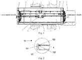
- the double-layered containment includes an outer containment 1 and an inner containment 2, and an inner pre-buried penetrating piece 4 and an outer pre-buried penetrating piece 3 are arranged on the outer containment 1 and the inner containment 2 correspondingly.
- the personnel gate penetrates through the inner pre-buried penetrating piece 4 and the outer pre-buried penetrating piece 3, the inner pre-buried penetrating piece 4 is fixedly connected to the personnel gate, and the outer pre-buried penetrating piece 3 is flexibly connected to the personnel gate in a sealed mode.
- the nuclear power plant personnel gate includes: a shell ring assembly 5, passing through the inner pre-buried penetrating piece 4 and the outer pre-buried penetrating piece 3, to support the the inner pre-buried penetrating piece 4 and the outer pre-buried penetrating piece 3; an outer sealing door 6 movably arranged at one side of the shell ring assembly 5 close to the outer containment 1, for establishing a shielding sealing barrier on the boundary of the outer containment 1; an inner sealing door 7, movably arranged at one side of the shell ring assembly 5 close to the inner containment 2, for establishing a pressure-bearing sealing barrier on the boundary of the inner containment 2; the shell ring assembly 5, the outer sealing door 6, and the inner sealing door 7 jointly enclose a sealed space 8; and an intermediate transmission cartridge 9 detachably disposed in the sealed space 8 and movably connected to the inner sealing door 7 and the outer sealing door 6, for controlling opening and closing of the the inner sealing door 7 and the outer sealing door 6.
- a passage floor 12 is provided in the sealed space 8 for the staff to pass through, and the passage floor 12 has a length no less than that of the sealed spaces 8.
- the shell ring assembly 5 includes an inner shell ring 51, an outer shell ring 52, and an intermediate shell ring 53 fixedly connected to the inner shell ring 51 and the outer shell ring 52.
- the inner shell ring 51 is connected to the inner sealing door 7, and the outer shell ring 52 is connected to the outer sealing door 6, the inner pre-buried penetrating piece 4 is fixedly connected to the intermediate shell ring 53 through a cantilever connection support ring plate 10 to support the personnel gate to the inner pre-buried penetrating piece 4, to improve the displacement synchronization of double-layer containment.
- the outer pre-buried penetrating piece 3 is flexibly and sealingly connected to the ntermediate shell ring 53 through a displacement compensation assembly 11, to compensate the displacement deviation of the intermediate shell ring 53 and the outer pre-buried penetrating piece 3 in the civil installation and earthquake environment, and ensure the sealing between the outer containment 1 and the ring corridor of the inner containment 2.
- the cantilevered connection support ring plate 10 includes: a support plate body 101 having one end fixedly connected to the intermediate shell ring 53 and other end extending upwardly, the support plate body 101 having a height higher than a height of the inner pre-buried penetrating piece 4, and the support plate body 101 being welded and connected to the inner pre-buried penetrating piece 4 through a circumferential weld 103; and a backing plate 102 arranged below the inner pre-buried penetrating piece 4 and fixedly connected to the support plate body 101.
- the welding quality of the girth weld can be ensured, the fixation reliability of the inner pre-buried penetrating piece 4 and the intermediate shell ring 53 can be ensured. In this manner, the entire personnel gate equipment can be supported on the inner pre-buried penetrating piece 4.
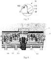
- the displacement compensation assembly 11 includes a first clamp 111 and a second clamp 112 correspondingly disposed on the intermediate shell ring 53 and the outer pre-buried penetrating piece 3, and a displacement compensation body 113 connecting the intermediate shell ring 53 and the outer pre-buried penetrating piece 3.
- One end of the displacement compensation body 113 is fixed on the outer pre-buried penetrating piece 3 via the first clamp 111, and the other end of the displacement compensation body 113 is fixed on the intermediate shell ring 53 via the second clamp 112. Due to the arrangement of the displacement compensation assembly 11, the sealing performance of the corridor space between the outer containment 1 and the inner containment 2 can be ensured, and the leakage of radioactive substances can be prevented.
- the displacement compensation body 113 includes multiple layers of materials, an inner layer is a reinforcing cloth with high tensile strength to improve sealing performance, an outer layer is a protective ceramic cloth to improve fire performance, the inner layer is assembled by thermal welding at the construction site and the outer layer is assembled by stitching. An inner surface of the inner layer of the displacement compensation body 113 is coated with a high temperature resistant food-grade silica gel coating, to improve the high temperature resistance. It should be noted that, in installation of the displacement compensation assembly 11, the displacement compensation assembly 11 is actually installed around the site.
- the intermediate transmission cartridge 9 has an accommodating space, and a multilayer transmission assembly 91 is movably arranged in the accommodation space.
- the multilayer transmission assembly 91 is detachably connected to the intermediate transmission cartridge; each multilayer transmission assembly 91 is driven by gears, and the multilayer transmission assembly 91 drives the inner sealing door 7 and the outer sealing door 6, and realizes the opening of the inner sealing door 7 and the outer sealing door 6 by means of mechanical interlocking.
- Adopting gear transmission instead of chain transmission, will further improve the transmission efficiency and transmission accuracy, and effectively eliminate the problem of the rebound impact of the sealing door caused by the chain transmission.
- the multilayer transmission assembly 91 includes: a power source module 911, a drive and pressure balance module 912, and an interlocking mechanism module 913;
- the power source module 911 is arranged at the bottom of the intermediate transmission cartridge 9, to generate driving force manually or electrically;
- the accommodating space is provided with a first connecting assembly 914 fixed on the bottom of the intermediate transmission cartridge 9, and a second connecting assembly 915 and a third connecting assembly 916 fixed on the side wall of the intermediate transmission cartridge 9.
- the first connecting assembly 914, the second connecting assembly 915 and the third connecting assembly 916 are respectively detachably connected to the power source module 911, the drive and pressure balance module 912 and the interlocking mechanism module 913. Due to the arrangement of the first connecting assembly 914, the second connecting assembly 915 and the third connecting assembly 916, the installation of the intermediate transmission cartridge 9 can be decoupled from the multilayer transmission assembly 91, so that the multilayer transmission assembly 9 can be installed when the operation is required after the installation of the personnel gate.
- the multilayer transmission assembly 9 is exempted from the maintenance requirements during the on-site installation, commissioning and maintenance of the power station. In the subsequent operation, if maintenance is required, it can be disassembled and replaced at any time.
- the multilayer transmission assembly 91 and the first connecting assembly 914, the second connecting assembly 915 and the third connecting assembly 916 can be detachable by connecting detachable parts such as bearings, bearing seats and bolts.
- the specific setting position of each component can be set according to actual needs, as long as the driving force can be stably transmitted when the transmission assembly is working and the transmission assembly is detachable.
- the power source module 911 includes: a motor 9111, a reducer 9112 connected to the output end of the motor 9111, a first input shaft 9113 and a second input shaft 9114 connected to the output end of the reducer 9112, and a first output shaft 9115 and a second output shaft 9116 corresponding to the first input shaft 9113 and the second input shaft 9114, a first clutch 9117 installed between the first input shaft 9113 and the first output shaft 9115, a second clutch 9118 mounted between the second input shaft 9114 and the second output shaft 9116, the first input shaft 9113 and the second input shaft 9114 drive the corresponding first output shaft 9115 and second output shaft 9116 to output driving force or disengage from the first output shaft 9115 and second output shaft 9116 through the first clutch 9117 and the second clutch 9118.
- the power source module 911 further includes: a first driving gear 9119 and a second driving gear 91110 correspondingly sleeved on the first output shaft 9115 and the second output shaft 916, to transmit the driving force generated by the motor 9111 to the drive and pressure balance module 912.
- the power source module 911 further includes: a first manual shaft 91111, a second manual shaft 91119, a first manual shaft driven gear 91112 correspondingly connected to the first manual shaft 91111, a first manual shaft driving gear 91113 meshing with the first manual shaft driven gear 91112, the first manual shaft driving gear 91113 is sleeved on the third input shaft 91114, the third input shaft 91114 is also sleeved with a first steering device 91115 and a third clutch 91117, the second manual shaft 91119 is sleeved with a second steering gear 91116 and a fourth clutch 91118, the third input shaft 91114 and the second manual shaft 91119 drive the corresponding first output shaft 9115 and the second output shaft 9116 to output driving force or disengage from the first output shaft 9115 and the second output shaft 9116 through the third clutch 91117 and the fourth clutch 91118.
- the drive and pressure balance module 912 includes: a fifth input shaft 9121, a sixth input shaft 9122, and a first driven gear 9123, a first interlock driving gear 9125 and a first pressure driving gear 9127 sleeved on the fifth input shaft 9121; a second driven gear 9124, a second interlock driving gear 9126, a second pressure driving gear 9128 sleeved on the sixth input shaft 9122; the first driven gear 9123 and the second driven gear 9124 mesh with the first driving gear 9119 and the second driving gear 91110.
- One end of the fifth input shaft 9121 and the sixth input shaft 9122 each is respectively connected to the inner sealing door 7 and the outer sealing door 6, to drive the opening and closing of the inner sealing door 7 and the outer sealing door 6.
- the first interlock driving gear 9125 and the second interlock driving gear 9126 are configured to transmit the driving force to the interlocking mechanism module 913.
- the drive and pressure balance module 912 further includes: a first pressure balance shaft 9129 and a second pressure balance shaft 91210.
- the first pressure driven gear 91211 is sleeved on the first pressure balance shaft 9129, the first pressure driven gear 91211 is meshed with the first pressure driving gear 9127 for transmitting the driving force to the first pressure balance shaft 9129.
- the second pressure driven gear 91212 is sleeved on the second pressure balance shaft 91210, the second pressure driven gear 91212 is meshed with the second pressure driving gear 9128 for transmitting the driving force to the second pressure balance shaft 91210.
- One end of the first pressure balance shaft 9129 and the second pressure balance shaft 91210 is connected to the pressure balance mechanism, to drive the pressure balance mechanism to open and close under the action of the driving force.
- the drive and pressure balance module 912 further includes: a first safety clutch 91213 sleeved on the fifth input shaft 9121 and a second safety clutch 91214 sleeved on the sixth input shaft 9122.
- the first safety clutch 91213 is arranged between the first interlock driving gear 9125 and the first driven gear 9123.
- the second safety clutch 91214 is provided between the second interlock driving gear 9126 and the second driven gear 9124, to realize overload protection.
- the interlocking mechanism module 913 includes: a first interlock output shaft 9131, a second interlock output shaft 9132, and a first interlock driven gear 9133 and a second interlock driven gear 9134 correspondingly sleeved on one end of the first interlock output shaft 9131 and the second interlock output shaft 9132.
- the first interlock driven gear 9133 and the second interlock driven gear 9134 are meshed with the second interlock driving gear 9126 and the first interlock driving gear 9125 respectively, for transmitting the driving force to the first interlock output shaft 9131 and the second interlock output shaft 9132.
- the interlocking mechanism module 913 further includes: an interlock unit 9135, the interlock unit 9135 is connected to the first interlock output shaft 9131 and the second interlock output shaft 9132.
- the interlock unit 9135 includes a first spline 91351 arranged on the first interlock output shaft 9131, a second spline 91352 arranged on the second interlock output shaft 9132.
- the interlock unit 9135 further includes a spanner 91353, the spanner 91353 is connected to the first spline 91351 and the second spline 91352 respectively, so as to drive the disconnection or combination of the first spline 91351 and the second spline 91352, to realize unilateral or bilateral opening of the inner sealing door 7 and the outer sealing door 6.
- the inner sealing door 7 includes a sealing door body 71 and a door frame 72.
- the sealing door body 71 is connected to the intermediate transmission cartridge 9, the door frame 72 is fixedly connected to the shell ring assembly 5, and the sealing door body 71 is locked to the door frame 72 via a seal locking device 73.
- the seal locking device 73 includes a first commutator 731, connected to the intermediate transmission cartridge 9, to change the direction of the driving force output by the intermediate transmission cartridge 9; a transmission assembly 732, connected to the first commutator 731 for transmitting the driving force transmitted by the first commutator 731; a locking assembly 733, connected to the transmission assembly 732, for locking the sealing door body 71 to the door frame 72 under the action of the driving force.
- the transmission assembly 732 includes: a first output shaft 7321 connected to the first commutator 731 and a first sprocket wheel 7322 sleeved on the first output shaft 7321.
- the first sprocket wheel 7322 and the second sprocket 7323 sleeved on the hinge mechanism 7324 are connected via a first chain 7325, the second sprocket wheel 7323 drives the hinge mechanism 7324 to rotate, and a third sprocket wheel 7326 sleeved on the hinge mechanism 7324 rotates under the rotation of the hinge mechanism 7324.
- the third sprocket wheel 7326 is connected to the fourth sprocket wheel 7327 through a second chain 7328, the fourth sprocket wheel 7327 is connected to the second commutator 7330 through a third output shaft 7329.
- the second commutator 7330 is sleeved on one end of the horizontal drive link 7331
- the third commutator 7332 is sleeved on the other end of the horizontal drive link 7331
- the output ends of the third commutator 7332 are respectively connected to the first vertical driving link 7333 and the second vertical driving link 7334.
- the first vertical driving link 7333 is connected to a fourth commutator 7335
- the second vertical driving link 7334 is connected to a fifth commutator 7336, to transmit the driving force to the fourth commutator 7335 and the fifth commutator 7336 after the driving force changes.
- the fourth commutator 7335 and the fifth commutator 7336 are both connected to the locking assembly 733, so as to transmit the driving force to the locking assembly 733.
- the locking assembly 733 includes: a first telescopic rod 741, a second telescopic rod 742, a first locking lever 749, a second locking lever 7410, a first bolt 743 and a second bolt 744 fixed on the sealing door body 71, a third bolt 744 and a fourth door bolt 746 fixed on the door frame 72, a first ball joint 747 connecting the first telescopic rod 741 and the first locking lever 749, and a second ball joint 748 connecting the second telescopic rod 742 and the second locking lever 7410.
- One end of the first telescopic rod 741 is connected to one of the output ends of the fourth commutator 7335, and the other end of the first telescopic rod 741 is connected to the first ball joint 747, the other end of the first ball joint 747 is connected to one end of the first locking lever 749, the other end of the first locking lever 749 slidly extends through the first bolt 743 and the third bolt 745, one end of the second telescopic rod 742 is connected to the other output end of the fourth commutator 7335, the other end of the second telescopic rod 742 is connected to the second ball joint 748, the other end of the second ball joint 748 is connected with one end of the second locking lever 7410, the other end of the second locking lever 7410 slidly extends through the second bolt 744 and the fourth bolt 746.
- the first telescopic rod 741 and the second telescopic rod 742 can be driven by the driving force to lengthen or shorten, so that the first locking lever 749 extends into or out of the third bolt 745; the second locking lever 7410 extends into or out of the fourth bolt 746.
- the locking assembly 733 further includes: a third telescopic rod 751, a fourth telescopic rod 752, a third locking lever 759, a fourth locking lever 7510, a fifth bolt 753 and a sixth bolt 754 fixed on the sealing door body 71, a seventh bolt 755 and an eighth bolt 756 fixed on the door frame 20, a third ball joint 757 connecting the third telescopic rod 751 and the third locking lever 759, a fourth ball joint 758 connecting the fourth telescopic rod 759 and the fourth locking lever 7510.
- One end of the third telescopic rod 751 is connected to one of the output ends of the fifth commutator 7336, the other end of the third telescopic rod 751 is connected with the third ball joint 757, the other end of the third ball joint 757 is connected with one end of the third locking lever 759, other end of the third locking lever 759 slidely extends through the fifth bolt 753 and the seventh bolt 755.
- One end of the fourth telescopic rod 752 is connected to the other output end of the fifth commutator 7336, the other end of the fourth telescopic rod 752 is connected with the fourth ball joint 758, the other end of the fourth ball joint 758 is connected with one end of the fourth locking lever 7510, the other end of the fourth locking lever 7510 slidely extends through the sixth bolt 754 and the eighth bolt 756.
- the third telescopic rod 751 and the fourth telescopic rod 752 are driven by the driving force to lengthen or shorten, so that the third locking lever 329 can extend into or out of the seventh bolt 325, and the fourth locking lever 7510 can extend into or out of the eighth bolt 756.
- the telescopic rod and the locking lever are connected by a ball joint, and the deflection angle of the ball joint can be adjusted in real time, which can solve the problem that the locking lever is stuck due to eccentric load during the bolt insertion process.
- the present invention also provides an installation method of a nuclear power plant personnel gate, as shown in Fig. 7 : the installation method includes the steps of:
- the personnel gate equipment is required to complete the equipment assembly and the factory joint adjustment test before leaving the factory, which effectively improves the assembly accuracy of the equipment, avoids the problems of low assembly accuracy, easy rework and unqualified on-site acceptance tests that exist in the on-site segmented installation.
- the on-site installation operation period of the personnel gate introduced into the installation scheme is short, and the operating space required is small, which facilitates the on-site construction of other items.
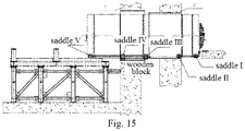
- installation tools used to introduce the overall horizontal installation position include: a first sliding bracket, a second sliding bracket, a transfer trolley and a support bracket A.
- the first sliding bracket and the second sliding bracket are fixed on two ends of the transfer trolley, and the transfer trolley and the support bracket A are fixedly connected by bolts.
- the first sliding bracket includes saddle III, saddle IV and saddle V
- Saddle III, saddle IV and saddle V are parallel to each other, and are in the shape of an arc, to couple with the shell ring assembly 5.
- Saddle III, Saddle IV and Saddle V are joined together by two support beams.
- the second sliding bracket includes a saddle I, a saddle II.
- the saddle I and the saddle II are also connected together by two support beams, which are also in the shape of an arc.
- the transfer trolley includes 6 columns, namely Column I, Column II, Column III, Column IV, Column V, and Column VI, the 6 columns are fixed on two parallel rails.
- the transport trolley is formed with four universal wheels at four bottom corners thereof, to drive the personnel gate to slide, which is convenient and labor-saving.
- the support bracket A is a support frame composed of several sections of steel.
- the support bracket A is used to support the transfer trolley.
- the personnel gate can be raised to a preset height before installation, to improve the reliability of installation.
- the support bracket A is supported on the outer containment 1 through the wooden block, to prevent the support bracket from being displaced when the personnel gate is introduced horizontally as a whole, and improve the reliability of the installation.
- One end of the wooden block is fixedly connected to the outer containment 1, and the other end is fixedly connected to the support bracket.
- the adjusting gasket set to adjust the elevation of the transfer trolley, the elevation of the transfer trolley can be adjusted and the applicability of the installation method is enhanced.
- a passage platform is set on one side of the inner containment 2, and a chain is drawn out from the passage platform.
- One end of the chain is fixedly connected to the passage platform, and the other end of the chain is fixedly connected to the personnel door.
- the location of the personnel gate is shown in Fig. 14 .
- the installation method of a nuclear power plant personnel gate of the present invention realizes installation by sliding, the operation space is small, the operation period is short, and it has great application significance.
- the present invention provides a nuclear power plant personnel gate and an installation method thereof, aiming at the technical problem in the prior art that the leakage rate of the nuclear power plant personnel gate does not meet the actual requirements, can obtain the sealing and continuity of the enter and exit passages of the double-layered containment. Due to the arrangement of the cantilever connection support ring plate, the impact of the double-layer containment displacement asynchrony on the on-site installation of the personnel gate can be solved.
- the inner and outer pre-buried penetrating pieces are conneted, to compensate for the displacement deviation of the two penetrating pieces in civil installation, earthquake and other environments, ensure the sealing between the penetrating pieces and the double-layer containment ring corridor, the flexible seals can be welded and clamped on site.
- the seal and the penetrating piece can be installed separately, and subsequent replacement is more convenient.
- the intermediate transmission cartridge of the present invention also adopts gear transmission instead of chain transmission, which improves transmission efficiency and greatly improves transmission accuracy. The impact rebound problem during the opening or closing process of the sealing door brought by the chain drive is eliminated.
- the locking of the sealing door is realized by the locking device, which solves the problem of the accuracy and synchronization of the locking operation of the personnel gate sealing door.
- the installation method is proposed, in which the personnel gate equipment is required to complete the equipment assembly and the factory joint adjustment test before leaving the factory, which effectively improves the assembly accuracy of the equipment, avoids the problems of low assembly accuracy, easy rework and unqualified on-site acceptance tests that exist in the on-site segmented installation.
- the on-site installation operation period of the personnel gate introduced into the installation scheme is short, and the operating space required is small, which facilitates the on-site construction of other items.
Landscapes
- Physics & Mathematics (AREA)
- Engineering & Computer Science (AREA)
- General Engineering & Computer Science (AREA)
- High Energy & Nuclear Physics (AREA)
- Plasma & Fusion (AREA)
- Pressure Vessels And Lids Thereof (AREA)
Abstract
Description
- The present invention generally relates to nuclear power plants, and more particularly, relates to a nuclear power plant personnel gate and installation method thereof.
- Generally, nuclear reactors are equipped with containment systems. In normal operating conditions, abnormal operating conditions and accident conditions, it is necessary to maintain the integrity and sealing of the containment pressure boundary, to prevent the leakage of radioactive materials. As an important part of the pressure boundary of the nuclear reactor containment, the nuclear power plant personnel gate also needs to undertake the same functional requirements. However, the conventional nuclear power plant personnel gates have the disadvantages of unsatisfactory sealing leakage rate, low transmission precision, and inconvenient installation process.
- What is needed, therefore, is to provide a nuclear power plant personnel gate and installation method thereof, to solve the technical problem that the sealing leakage rate of the conventional nuclear power plant personnel gate does not meet the requirements of actual use.
- One object of the present invention is is to provide a nuclear power plant personnel gate and installation method thereof, to solve the technical problem that the sealing leakage rate of the conventional nuclear power plant personnel gate does not meet the requirements of actual use.
- According to one embodiment of the present invention, a nuclear power plant personnel gate, applicable to a double-layered containment of a nuclear power plant, the double-layered containment including an outer containment and an inner containment, the inner containment and the outer containment being correspondingly provided with an inner pre-buried penetrating piece and an outer pre-buried penetrating piece, and the personnel gate passing through the inner pre-buried penetrating piece and the outer pre-buried penetrating piece, wherein the inner pre-buried penetrating piece is fixedly connected to the personnel gate, and the outer pre-buried penetrating piece is flexibly connected to the personnel gate in a sealed mode. The nuclear power plant personnel gate includes: a shell ring assembly passing through and supporting the inner pre-buried penetrating piece and the outer pre-buried penetrating piece; an outer sealing door movably arranged at one side of the shell ring assembly close to the outer containment, for establishing a shielding sealing barrier on the boundary of the outer containment; an inner sealing door, movably arranged at one side of the shell ring assembly close to the inner containment, for establishing a pressure-bearing sealing barrier on the boundary of the inner containment; the shell ring assembly, the outer sealing door, and the inner sealing door jointly enclose a sealed space; and an intermediate transmission cartridge detachably disposed in the sealed space and movably connected to the inner sealing door and the outer sealing door, for controlling opening and closing of the the inner sealing door and the outer sealing door.
- According to one embodiment of the nuclear power plant personnel gate of the present invention, the shell ring assembly includes: an inner shell ring, an outer shell ring, and an intermediate shell ring fixedly connected to the inner shell ring and the outer shell ring, the inner shell ring is connected to the inner sealing door, and the outer shell ring is connected to the outer sealing door, the inner pre-buried penetrating piece is fixedly connected to the intermediate shell ring through a cantilever connection support ring plate, to support the personnel gate to the pre-buried penetrating piece and improve the synchronization of the displacement of the double-layer containment. The outer pre-buried penetrating piece is flexibly and sealingly connected to the ntermediate shell ring through a displacement compensation assembly, to compensate the displacement deviation of the intermediate shell ring and the outer shell ring in the civil installation and earthquake environment, and ensure the sealing between the outer containment and the inner containment ring corridor.
- According to one embodiment of the nuclear power plant personnel gate of the present invention, the cantilever connection support ring plate includes: a support plate body having one end fixedly connected to the intermediate shell ring and other end extending upwardly, the support plate body having a height higher than a height of the inner pre-buried penetrating piece, and the support plate body being welded and connected to the inner pre-buried penetrating piece through a circumferential weld; and a backing plate arranged below the inner pre-buried penetrating piece and fixedly connected to the support plate body.
- According to one embodiment of the nuclear power plant personnel gate of the present invention, the displacement compensation assembly includes a first clamp and a second clamp correspondingly disposed on the intermediate shell ring and the outer pre-buried penetrating piece, and a displacement compensation body connecting the intermediate shell ring and the outer pre-buried penetrating piece, one end of the displacement compensation body is fixed on the outer pre-buried penetrating piece via the first clamp, and the other end of the displacement compensation body is fixed on the intermediate shell ring via the second clamp.
- According to one embodiment of the nuclear power plant personnel gate of the present invention, the displacement compensation body includes multiple layers of materials, an inner layer is a reinforcing cloth with high tensile strength to improve sealing performance, an outer layer is a protective ceramic cloth to improve fire performance, and the inner layer is assembled by thermal welding at the construction site and the outer layer is assembled by stitching.
- According to one embodiment of the nuclear power plant personnel gate of the present invention, an inner surface of the inner layer of the displacement compensation body is coated with a high temperature resistant food-grade silica gel coating, to improve the high temperature resistance performance thereof.
- According to one embodiment of the nuclear power plant personnel gate of the present invention, the intermediate transmission cartridge has an accommodating space, a multilayer transmission assembly is movably arranged in the accommodating space, and the multilayer transmission assembly is detachably connected to the intermediate transmission cartridge; each multilayer transmission assembly is driven by gears, and the multilayer transmission assembly drives the inner sealing door and the outer sealing door, and realizes the opening of the inner sealing door and the outer sealing door by means of mechanical interlocking.
- According to one embodiment of the nuclear power plant personnel gate of the present invention, the multilayer transmission assembly includes: a power source module, a drive and pressure balance module and an interlocking mechanism module; the power source module is arranged at a bottom of the intermediate transmission cartridge to generate driving power manually or electrically; an input end of the drive and pressure balance module is connected to the power source module, and an output end of the drive and pressure balance module is respectively connected to a pressure balance mechanism, the inner sealing door, the outer sealing door and the interlocking mechanism module, for transmitting the driving force to the pressure balance mechanism, the inner sealing door and the outer sealing door to realize opening and closing of the sealing door and the operation of the pressure balance mechanism, and transmitting the driving force to the interlocking mechanism module; the interlocking mechanism module is arranged on a top of the intermediate transmission cartridge, and controls unilateral or bilateral opening of the inner sealing door and the outer sealing door according to the driving force; the accommodating space is provided with a first connecting assembly therein fixed on the bottom of the intermediate transmission cartridge and a second connecting assembly and a third connecting assembly fixed on a side wall of the intermediate transmission cartridge, the first connecting assembly, the second connecting assembly and the third connecting assembly are respectively detachably connected to the power source module, the drive and pressure balance module and the interlocking mechanism module.
- According to one embodiment of the nuclear power plant personnel gate of the present invention, the power source module includes: a motor, a reducer connected to an output end of the motor, a first input shaft and a second input shaft connected to an output end of the reducer, and a first output shaft and a second output shaft corresponding to the first input shaft and the second input shaft, a first clutch mounted between the first input shaft and the first output shaft, a second clutch mounted between the the second input shaft and the second output shaft, the first input shaft and the second input shaft drive the corresponding first output shaft and second output shaft to output driving force or disengage from the first output shaft and second output shaft through the first clutch and the second clutch; a first driving gear and a second driving gear correspondingly sleeved on the first output shaft and the second output shaft, the drive force generated by the motor is transmitted to the drive and pressure balance module.
- According to one embodiment of the nuclear power plant personnel gate of the present invention, the power source module further includes: a first manual shaft, a second manual shaft, a first manual shaft driven gear correspondingly connected to the first manual shaft, a first manual shaft driving gear meshing with the first manual shaft driven gear, the first manual shaft driving gear is sleeved on the third input shaft, the third input shaft is also sleeved with a first steering device and a third clutch, the second manual shaft is sleeved with a second steering gear and a fourth clutch, the third input shaft and the second manual shaft drive the corresponding first output shaft and the second output shaft to output driving force or disengage from the first output shaft and the second output shaft through the third clutch and the fourth clutch.
- According to one embodiment of the nuclear power plant personnel gate of the present invention, the drive and pressure balance module includes: a fifth input shaft, a sixth input shaft, and a first driven gear, a first interlock driving gear and a first pressure driving gear sleeved on the fifth input shaft; a second driven gear, a second interlock driving gear, a second pressure driving gear sleeved on the sixth input shaft; the first driven gear and the second driven gear mesh with the first driving gear and the second driving gear; one end of the fifth input shaft and the sixth input shaft each is respectively connected to the inner sealing door and the outer sealing door, to drive the opening and closing of the inner sealing door and the outer sealing door; the first interlock driving gear and the second interlock driving gear are configured to transmit the driving force to the interlocking mechanism module.
- According to one embodiment of the nuclear power plant personnel gate of the present invention, the drive and pressure balance module further includes: a first pressure balance shaft and a second pressure balance shaft, the first pressure driven gear is sleeved on the first pressure balance shaft, the first pressure driven gear is meshed with the first pressure driving gear for transmitting the driving force to the first pressure balance shaft, the second pressure driven gear is sleeved on the second pressure balance shaft, the second pressure driven gear is meshed with the second pressure driving gear for transmitting the driving force to the second pressure balance shaft, one end of the first pressure balance shaft and the second pressure balance shaft is connected to the pressure balance mechanism, to drive the pressure balance mechanism to open and close under the action of the driving force.
- According to one embodiment of the nuclear power plant personnel gate of the present invention, the drive and pressure balance module further includes: a first safety clutch sleeved on the fifth input shaft and a second safety clutch sleeved on the sixth input shaft, the first safety clutch is arranged between the first interlock driving gear and the first driven gear, the second safety clutch is provided between the second interlock driving gear and the second driven gear, to realize overload protection.
- According to one embodiment of the nuclear power plant personnel gate of the present invention, the interlocking mechanism module includes: a first interlock output shaft, a second interlock output shaft, and a first interlock driven gear and a second interlock driven gear correspondingly sleeved on one end of the first interlock output shaft and the second interlock output shaft, the first interlock driven gear and the second interlock driven gear are meshed with the second interlock driving gear and the first interlock driving gear respectively, for transmitting the driving force to the first interlock output shaft and the second interlock output shaft.
- According to one embodiment of the nuclear power plant personnel gate of the present invention, the interlocking mechanism module further includes: an interlock unit, the interlock unit is connected to the first interlock output shaft and the second interlock output shaft, the interlock unit includes a first spline arranged on the first interlock output shaft, a second spline arranged on the second interlock output shaft, the interlock unit further includes a spanner, the spanner is connected to the first spline and the second spline respectively, so as to drive the disconnection or combination of the first spline and the second spline, to realize unilateral or bilateral opening of the inner sealing door and the outer sealing door.
- According to one embodiment of the nuclear power plant personnel gate of the present invention, the inner sealing door includes a sealing door body and a door frame, the sealing door body is connected to the intermediate transmission cartridge, the door frame is fixedly connected to the shell ring assembly, and the sealing door body is locked to the door frame via a seal locking device, the seal locking device includes: a first commutator, connected to the intermediate transmission cartridge, to change the direction of the driving force output by the intermediate transmission cartridge; a transmission assembly, connected to the first commutator for transmitting the driving force transmitted by the first commutator; a locking assembly, connected to the transmission assembly, for locking the sealing door body to the door frameunder the action of the driving force.
- According to one embodiment of the nuclear power plant personnel gate of the present invention, the transmission assembly includes: a first output shaft connected to the first commutator and a first sprocket wheel sleeved on the first output shaft, the first sprocket wheel and the second sprocket sleeved on the hinge mechanism are connected via a first chain, the second sprocket wheel drives the hinge mechanism to rotate, and a third sprocket wheel sleeved on the hinge mechanism rotates under the rotation of the hinge mechanism, the third sprocket wheel is connected to the fourth sprocket wheel through a second chain, the fourth sprocket wheel is connected to the second commutator through a third output shaft, the second commutator is sleeved on one end of the horizontal drive link, the third commutator is sleeved on the other end of the horizontal drive link, the output ends of the third commutator are respectively connected to the first vertical driving link and the second vertical driving link, the first vertical driving link is connected to a fourth commutator, the second vertical driving link is connected to a fifth commutator, the fourth commutator and the fifth commutator are both connected to the locking assembly, to transmit the driving force to the locking assembly.
- According to one embodiment of the nuclear power plant personnel gate of the present invention, the locking assembly includes: a first telescopic rod, a second telescopic rod, a first locking lever, a second locking lever, a first bolt and a second bolt fixed on the sealing door body, a third bolt and a fourth door bolt fixed on the door frame, a first ball joint connecting the first telescopic rod and the first locking lever, a second ball joint connecting the second telescopic rod and the second locking lever, one end of the first telescopic rod is connected to one of the output ends of the fourth commutator, and the other end of the first telescopic rod is connected to the first ball joint, the other end of the first ball joint is connected to one end of the first locking lever, the other end of the first locking lever slidly extends through the first bolt and the third bolt, one end of the second telescopic rod is connected to the other output end of the fourth commutator, the other end of the second telescopic rod is connected to the second ball joint, the other end of the second ball joint is connected with one end of the second locking lever, the other end of the second locking lever slidly extends through the second bolt and the fourth bolt, the first telescopic rod and the second telescopic rod can be driven by the driving force to lengthen or shorten, so that the first locking lever extends into or out of the third bolt; the second locking lever extends into or out of the fourth bolt.
- According to one embodiment of the nuclear power plant personnel gate of the present invention, the locking assembly further comprises: a third telescopic rod, a fourth telescopic rod, a third locking lever, a fourth locking lever, a fifth bolt and a sixth bolt fixed on the sealing door body, a seventh bolt and an eighth bolt fixed on the door frame, a third ball joint connecting the third telescopic rod and the third locking lever, a fourth ball joint connecting the fourth telescopic rod and the fourth locking lever, one end of the third telescopic rod is connected to one of the output ends of the fifth commutator, the other end of the third telescopic rodis connected with the third ball joint, the other end of the third ball joint is connected with one end of the third locking lever, other end of the third locking lever slidely extends through the fifth bolt and the seventh bolt, one end of the fourth telescopic rod is connected to the other output end of the fifth commutator, the other end of the fourth telescopic rod is connected with the fourth ball joint, the other end of the fourth ball joint is connected with one end of the fourth locking lever, the other end of the fourth locking lever slidely extends through the sixth bolt and the eighth bolt, and the third telescopic rod and the fourth telescopic rod are driven by the driving force to lengthen or shorten, so that the third locking lever can extend into or out of the seventh bolt, and the fourth locking lever can extend into or out of the eighth bolt.
- According to one embodiment of the nuclear power plant personnel gate of the present invention, a passage floor is provided in the sealed space for the staff to pass through, and the passage floor has a length no less than that of the sealed spaces.
- According to another embodiment of the present invention, an installation method of a nuclear power plant personnel gate, applicable to the nuclear power plant personnel gate according to the present invention is provided. The installation method includes the steps of: fixing a support bracket to a predetermined overall horizontal introduction installation position of the personnel gate via expansion bolts, the support bracket being supported on the outer containment via wooden blocks; installing a first sliding bracket, a second sliding bracket and a transfer trolley on the support bracket after the support bracket being connected and fixed, adjusting elevation of the transfer trolley by adjusting an adjusting gasket set, and fixing the transfer trolley via connecting bolts after the elevation of the transfer trolley is adjusted; hoisting the personnel gate vertically as a whole by an off-site crane, and fixing the personnel gate to the first sliding bracket and the second sliding bracket by wire ropes; installing pulling chains, pulling the personnel gate horizontally to a predetermined installation position, and removing the transfer trolley and the support bracket; and installing supports of the personnel gate, and removing the first sliding bracket and the first sliding bracket.
- Compared with the prior art, the nuclear power plant personnel gate of the present invention has the following advantages. The present invention provides a nuclear power plant personnel gate and an installation method thereof, aiming at the technical problem in the prior art that the leakage rate of the nuclear power plant personnel gate does not meet the actual requirements, can obtain the sealing and continuity of the enter and exit passages of the double-layered containment. Due to the arrangement of the cantilever connection support ring plate, the impact of the double-layer containment displacement asynchrony on the on-site installation of the personnel gate can be solved. Due to the arrangement of the displacement compensation assembly, the inner and outer pre-buried penetrating pieces are conneted, to compensate for the displacement deviation of the two penetrating pieces in civil installation, earthquake and other environments, ensure the sealing between the penetrating pieces and the double-layer containment ring corridor, the flexible seals can be welded and clamped on site. The seal and the penetrating piece can be installed separately, and subsequent replacement is more convenient. The intermediate transmission cartridge of the present invention also adopts gear transmission instead of chain transmission, which improves transmission efficiency and greatly improves transmission accuracy. The impact rebound problem during the opening or closing process of the sealing door brought by the chain drive is eliminated. The locking of the sealing door is realized by the locking device, which solves the problem of the accuracy and synchronization of the locking operation of the personnel gate sealing door. Finally, the installation method is proposed, in which the personnel gate equipment is required to complete the equipment assembly and the factory joint adjustment test before leaving the factory, which effectively improves the assembly accuracy of the equipment, avoids the problems of low assembly accuracy, easy rework and unqualified on-site acceptance tests that exist in the on-site segmented installation. The on-site installation operation period of the personnel gate introduced into the installation scheme is short, and the operating space required is small, which facilitates the on-site construction of other items.
- In order to make the objects, technical solutions and advantages of the present invention clearer, the embodiments of the present invention will be further described in detail with reference to the accompanying drawings, in which:
-
Fig.1 is a schematic structural diagram of a nuclear power plant personnel gate according to a first embodiment of the present invention; -
Fig. 2 is a schematic structural diagram of a cantilever connection support ring plate in the nuclear power plant personnel gate of the first embodiment of the present invention; -
Fig. 3 is a schematic structural diagram of a displacement compensation assembly in the nuclear power plant personnel gate of the first embodiment of the present invention; -
Fig. 4 is a schematic structural diagram of an intermediate transmission cartridge in the nuclear power plant personnel gate of the first embodiment of the present invention; -
Fig. 5 is a schematic diagram of internal structure of the intermediate transmission cartridge in the nuclear power plant personnel gate of the first embodiment of the present invention; -
Fig. 6 is a schematic structural diagram of a seal locking device in the nuclear power plant personnel gate of the first embodiment of the present invention; -
Fig. 7 is a flowchart of an installation method of a nuclear power plant personnel gate according to a second embodiment of the present invention; -
Fig. 8 is a schematic structural diagram of an installation tool in the installation method of a nuclear power plant personnel gate according to a second embodiment of the present invention; -
Fig. 9 is a schematic structural diagram of a first sliding bracket in the installation method of a nuclear power plant personnel gate according to a second embodiment of the present invention; -
Fig. 10 is a schematic structural diagram of a second sliding bracket in the installation method of a nuclear power plant personnel gate according to a second embodiment of the present invention; -
Fig. 11 is a schematic structural diagram of a transfer trolley in the installation method of a nuclear power plant personnel gate according to a second embodiment of the present invention; -
Fig. 12 is a schematic structural diagram of a support bracket in the installation method of a nuclear power plant personnel gate according to a second embodiment of the present invention; -
Fig. 13 is a schematic diagram in the installation method of a nuclear power plant personnel gate according to a second embodiment of the present invention, showing the installation tool being overall horizontally introduced to an installation position; -
Fig. 14 is a schematic diagram in the installation method of a nuclear power plant personnel gate according to a second embodiment of the present invention, showing the state of the personnel gate prior to being overall horizontally introduced; and -
Fig. 15 is a schematic diagram in the installation method of a nuclear power plant personnel gate according to a second embodiment of the present invention, showing the state of the personnel gate after being overall horizontally introduced. - In order to solve the problems of sealing and continuity of the equipment enter and exit passages existing in the prior art, the present invention aims to provide a nuclear power plant personnel gate and an installation method thereof. The core idea of the present invention is to provide a nuclear power plant personnel gate and an installation method thereof, which can obtain the sealing and continuity of the enter and exit passages of the double-layered containment. Due to the arrangement of the cantilever connection support ring plate, the impact of the double-layer containment displacement asynchrony on the on-site installation of the personnel gate can be solved. Due to the arrangement of the displacement compensation assembly, the inner and outer pre-buried penetrating pieces are conneted, to compensate for the displacement deviation of the two penetrating pieces in civil installation, earthquake and other environments, ensure the sealing between the penetrating pieces and the double-layer containment ring corridor, the flexible seals can be welded and clamped on site. The seal and the penetrating piece can be installed separately, and subsequent replacement is more convenient. The intermediate transmission cartridge of the present invention also adopts gear transmission instead of chain transmission, which improves transmission efficiency and greatly improves transmission accuracy. The impact rebound problem during the opening or closing process of the sealing door brought by the chain drive is eliminated. The locking of the sealing door is realized by the locking device, which solves the problem of the accuracy and synchronization of the locking operation of the personnel gate sealing door. Finally, the installation method is proposed, in which the personnel gate equipment is required to complete the equipment assembly and the factory joint adjustment test before leaving the factory, which effectively improves the assembly accuracy of the equipment, avoids the problems of low assembly accuracy, easy rework and unqualified on-site acceptance tests that exist in the on-site segmented installation. The on-site installation operation period of the personnel gate introduced into the installation scheme is short, and the operating space required is small, which facilitates the on-site construction of other items.
- In order to make the objects, technical solutions and technical effects of the present invention clearer, the specific embodiments of the present invention will be further described in detail below with reference to the accompanying drawings.
- The present invention provides a nuclear power plant personnel gate, which is applicable to a double-layered containment of a nuclear power plant. Referring to
Fig. 1 , the double-layered containment includes anouter containment 1 and aninner containment 2, and an inner pre-buriedpenetrating piece 4 and an outer pre-buriedpenetrating piece 3 are arranged on theouter containment 1 and theinner containment 2 correspondingly. The personnel gate penetrates through the inner pre-buriedpenetrating piece 4 and the outer pre-buriedpenetrating piece 3, the inner pre-buriedpenetrating piece 4 is fixedly connected to the personnel gate, and the outer pre-buriedpenetrating piece 3 is flexibly connected to the personnel gate in a sealed mode. - The nuclear power plant personnel gate includes: a shell ring assembly 5, passing through the inner pre-buried
penetrating piece 4 and the outer pre-buriedpenetrating piece 3, to support the the inner pre-buriedpenetrating piece 4 and the outer pre-buriedpenetrating piece 3; anouter sealing door 6 movably arranged at one side of the shell ring assembly 5 close to theouter containment 1, for establishing a shielding sealing barrier on the boundary of theouter containment 1; an inner sealing door 7, movably arranged at one side of the shell ring assembly 5 close to theinner containment 2, for establishing a pressure-bearing sealing barrier on the boundary of theinner containment 2; the shell ring assembly 5, theouter sealing door 6, and the inner sealing door 7 jointly enclose a sealed space 8; and anintermediate transmission cartridge 9 detachably disposed in the sealed space 8 and movably connected to the inner sealing door 7 and theouter sealing door 6, for controlling opening and closing of the the inner sealing door 7 and theouter sealing door 6. - According to a preferred embodiment of the present invention, a
passage floor 12 is provided in the sealed space 8 for the staff to pass through, and thepassage floor 12 has a length no less than that of the sealed spaces 8. - Further, the shell ring assembly 5 includes an
inner shell ring 51, anouter shell ring 52, and anintermediate shell ring 53 fixedly connected to theinner shell ring 51 and theouter shell ring 52. Theinner shell ring 51 is connected to the inner sealing door 7, and theouter shell ring 52 is connected to theouter sealing door 6, the inner pre-buriedpenetrating piece 4 is fixedly connected to theintermediate shell ring 53 through a cantilever connectionsupport ring plate 10 to support the personnel gate to the inner pre-buriedpenetrating piece 4, to improve the displacement synchronization of double-layer containment. The outer pre-buriedpenetrating piece 3 is flexibly and sealingly connected to thentermediate shell ring 53 through adisplacement compensation assembly 11, to compensate the displacement deviation of theintermediate shell ring 53 and the outer pre-buriedpenetrating piece 3 in the civil installation and earthquake environment, and ensure the sealing between theouter containment 1 and the ring corridor of theinner containment 2. - Further, referring to
Fig 2 , the cantilevered connectionsupport ring plate 10 includes: asupport plate body 101 having one end fixedly connected to theintermediate shell ring 53 and other end extending upwardly, thesupport plate body 101 having a height higher than a height of the inner pre-buriedpenetrating piece 4, and thesupport plate body 101 being welded and connected to the inner pre-buriedpenetrating piece 4 through acircumferential weld 103; and abacking plate 102 arranged below the inner pre-buriedpenetrating piece 4 and fixedly connected to thesupport plate body 101. Due to the arrangement of thebacking plate 102, the welding quality of the girth weld can be ensured, the fixation reliability of the inner pre-buriedpenetrating piece 4 and theintermediate shell ring 53 can be ensured. In this manner, the entire personnel gate equipment can be supported on the inner pre-buriedpenetrating piece 4. - Further, referring to
Fig. 3 , thedisplacement compensation assembly 11 includes afirst clamp 111 and asecond clamp 112 correspondingly disposed on theintermediate shell ring 53 and the outer pre-buriedpenetrating piece 3, and adisplacement compensation body 113 connecting theintermediate shell ring 53 and the outer pre-buriedpenetrating piece 3. One end of thedisplacement compensation body 113 is fixed on the outer pre-buriedpenetrating piece 3 via thefirst clamp 111, and the other end of thedisplacement compensation body 113 is fixed on theintermediate shell ring 53 via thesecond clamp 112. Due to the arrangement of thedisplacement compensation assembly 11, the sealing performance of the corridor space between theouter containment 1 and theinner containment 2 can be ensured, and the leakage of radioactive substances can be prevented. - Further, the
displacement compensation body 113 includes multiple layers of materials, an inner layer is a reinforcing cloth with high tensile strength to improve sealing performance, an outer layer is a protective ceramic cloth to improve fire performance, the inner layer is assembled by thermal welding at the construction site and the outer layer is assembled by stitching. An inner surface of the inner layer of thedisplacement compensation body 113 is coated with a high temperature resistant food-grade silica gel coating, to improve the high temperature resistance. It should be noted that, in installation of thedisplacement compensation assembly 11, thedisplacement compensation assembly 11 is actually installed around the site. - Further, referring to
Fig. 4 , theintermediate transmission cartridge 9 has an accommodating space, and amultilayer transmission assembly 91 is movably arranged in the accommodation space. Themultilayer transmission assembly 91 is detachably connected to the intermediate transmission cartridge;
eachmultilayer transmission assembly 91 is driven by gears, and themultilayer transmission assembly 91 drives the inner sealing door 7 and theouter sealing door 6, and realizes the opening of the inner sealing door 7 and theouter sealing door 6 by means of mechanical interlocking. Adopting gear transmission, instead of chain transmission, will further improve the transmission efficiency and transmission accuracy, and effectively eliminate the problem of the rebound impact of the sealing door caused by the chain transmission. - Specifically, the
multilayer transmission assembly 91 includes: apower source module 911, a drive andpressure balance module 912, and aninterlocking mechanism module 913; - The
power source module 911 is arranged at the bottom of theintermediate transmission cartridge 9, to generate driving force manually or electrically; - an input end of the drive and
pressure balance module 912 is connected to thepower source module 911, and the output end of the drive andpressure balance module 912 is respectively connected to the pressure balance mechanism, the inner sealing door 7, theouter sealing door 6 and theinterlocking mechanism module 913, for transmitting the driving force to the pressure balance mechanism, the inner sealing door 7 and theouter sealing door 6, to realize the opening and closing of the inner sealing door 7 and theouter sealing door 6 and the operation of the pressure balance mechanism; and to transmit the driving force to theinterlocking mechanism module 913; - the
interlocking mechanism module 913 is arranged on the top of theintermediate transmission cartridge 9, to control the unilateral or bilateral opening of the inner sealing door 7 and theouter sealing door 6 according to the driving force. - Further, the accommodating space is provided with a first connecting
assembly 914 fixed on the bottom of theintermediate transmission cartridge 9, and a second connectingassembly 915 and a third connectingassembly 916 fixed on the side wall of theintermediate transmission cartridge 9. The first connectingassembly 914, the second connectingassembly 915 and the third connectingassembly 916 are respectively detachably connected to thepower source module 911, the drive andpressure balance module 912 and theinterlocking mechanism module 913. Due to the arrangement of the first connectingassembly 914, the second connectingassembly 915 and the third connectingassembly 916, the installation of theintermediate transmission cartridge 9 can be decoupled from themultilayer transmission assembly 91, so that themultilayer transmission assembly 9 can be installed when the operation is required after the installation of the personnel gate. Themultilayer transmission assembly 9 is exempted from the maintenance requirements during the on-site installation, commissioning and maintenance of the power station. In the subsequent operation, if maintenance is required, it can be disassembled and replaced at any time. Preferably, themultilayer transmission assembly 91 and the first connectingassembly 914, the second connectingassembly 915 and the third connectingassembly 916 can be detachable by connecting detachable parts such as bearings, bearing seats and bolts. The specific setting position of each component can be set according to actual needs, as long as the driving force can be stably transmitted when the transmission assembly is working and the transmission assembly is detachable. - Specifically, referring to
Fig. 5 , thepower source module 911 includes: amotor 9111, areducer 9112 connected to the output end of themotor 9111, afirst input shaft 9113 and asecond input shaft 9114 connected to the output end of thereducer 9112, and afirst output shaft 9115 and asecond output shaft 9116 corresponding to thefirst input shaft 9113 and thesecond input shaft 9114, a first clutch 9117 installed between thefirst input shaft 9113 and thefirst output shaft 9115, a second clutch 9118 mounted between thesecond input shaft 9114 and thesecond output shaft 9116, thefirst input shaft 9113 and thesecond input shaft 9114 drive the correspondingfirst output shaft 9115 andsecond output shaft 9116 to output driving force or disengage from thefirst output shaft 9115 andsecond output shaft 9116 through the first clutch 9117 and the second clutch 9118. Thepower source module 911 further includes: afirst driving gear 9119 and asecond driving gear 91110 correspondingly sleeved on thefirst output shaft 9115 and thesecond output shaft 916, to transmit the driving force generated by themotor 9111 to the drive andpressure balance module 912. - Further, the
power source module 911 further includes: a firstmanual shaft 91111, a second manual shaft 91119, a first manual shaft drivengear 91112 correspondingly connected to the firstmanual shaft 91111, a first manualshaft driving gear 91113 meshing with the first manual shaft drivengear 91112, the first manualshaft driving gear 91113 is sleeved on thethird input shaft 91114, thethird input shaft 91114 is also sleeved with afirst steering device 91115 and athird clutch 91117, the second manual shaft 91119 is sleeved with asecond steering gear 91116 and afourth clutch 91118, thethird input shaft 91114 and the second manual shaft 91119 drive the correspondingfirst output shaft 9115 and thesecond output shaft 9116 to output driving force or disengage from thefirst output shaft 9115 and thesecond output shaft 9116 through thethird clutch 91117 and thefourth clutch 91118. - Further, the drive and
pressure balance module 912 includes: afifth input shaft 9121, asixth input shaft 9122, and a first drivengear 9123, a firstinterlock driving gear 9125 and a firstpressure driving gear 9127 sleeved on thefifth input shaft 9121; a second drivengear 9124, a secondinterlock driving gear 9126, a secondpressure driving gear 9128 sleeved on thesixth input shaft 9122; the first drivengear 9123 and the second drivengear 9124 mesh with thefirst driving gear 9119 and thesecond driving gear 91110. One end of thefifth input shaft 9121 and thesixth input shaft 9122 each is respectively connected to the inner sealing door 7 and theouter sealing door 6, to drive the opening and closing of the inner sealing door 7 and theouter sealing door 6. The firstinterlock driving gear 9125 and the secondinterlock driving gear 9126 are configured to transmit the driving force to theinterlocking mechanism module 913. - Further, the drive and
pressure balance module 912 further includes: a firstpressure balance shaft 9129 and a secondpressure balance shaft 91210. The first pressure drivengear 91211 is sleeved on the firstpressure balance shaft 9129, the first pressure drivengear 91211 is meshed with the firstpressure driving gear 9127 for transmitting the driving force to the firstpressure balance shaft 9129. The second pressure drivengear 91212 is sleeved on the secondpressure balance shaft 91210, the second pressure drivengear 91212 is meshed with the secondpressure driving gear 9128 for transmitting the driving force to the secondpressure balance shaft 91210. One end of the firstpressure balance shaft 9129 and the secondpressure balance shaft 91210 is connected to the pressure balance mechanism, to drive the pressure balance mechanism to open and close under the action of the driving force. - Further, the drive and
pressure balance module 912 further includes: afirst safety clutch 91213 sleeved on thefifth input shaft 9121 and asecond safety clutch 91214 sleeved on thesixth input shaft 9122. Thefirst safety clutch 91213 is arranged between the firstinterlock driving gear 9125 and the first drivengear 9123. Thesecond safety clutch 91214 is provided between the secondinterlock driving gear 9126 and the second drivengear 9124, to realize overload protection. - Further, the
interlocking mechanism module 913 includes: a firstinterlock output shaft 9131, a secondinterlock output shaft 9132, and a first interlock drivengear 9133 and a second interlock drivengear 9134 correspondingly sleeved on one end of the firstinterlock output shaft 9131 and the secondinterlock output shaft 9132. The first interlock drivengear 9133 and the second interlock drivengear 9134 are meshed with the secondinterlock driving gear 9126 and the firstinterlock driving gear 9125 respectively, for transmitting the driving force to the firstinterlock output shaft 9131 and the secondinterlock output shaft 9132. - Further, the
interlocking mechanism module 913 further includes: aninterlock unit 9135, theinterlock unit 9135 is connected to the firstinterlock output shaft 9131 and the secondinterlock output shaft 9132. Theinterlock unit 9135 includes afirst spline 91351 arranged on the firstinterlock output shaft 9131, asecond spline 91352 arranged on the secondinterlock output shaft 9132. Theinterlock unit 9135 further includes aspanner 91353, thespanner 91353 is connected to thefirst spline 91351 and thesecond spline 91352 respectively, so as to drive the disconnection or combination of thefirst spline 91351 and thesecond spline 91352, to realize unilateral or bilateral opening of the inner sealing door 7 and theouter sealing door 6. - Further, referring to
Fig. 6 , the inner sealing door 7 includes a sealingdoor body 71 and adoor frame 72. The sealingdoor body 71 is connected to theintermediate transmission cartridge 9, thedoor frame 72 is fixedly connected to the shell ring assembly 5, and the sealingdoor body 71 is locked to thedoor frame 72 via aseal locking device 73. Theseal locking device 73 includes afirst commutator 731, connected to theintermediate transmission cartridge 9, to change the direction of the driving force output by theintermediate transmission cartridge 9; atransmission assembly 732, connected to thefirst commutator 731 for transmitting the driving force transmitted by thefirst commutator 731; a lockingassembly 733, connected to thetransmission assembly 732, for locking the sealingdoor body 71 to thedoor frame 72 under the action of the driving force. - Further, the
transmission assembly 732 includes: afirst output shaft 7321 connected to thefirst commutator 731 and afirst sprocket wheel 7322 sleeved on thefirst output shaft 7321. Thefirst sprocket wheel 7322 and thesecond sprocket 7323 sleeved on thehinge mechanism 7324 are connected via afirst chain 7325, thesecond sprocket wheel 7323 drives thehinge mechanism 7324 to rotate, and athird sprocket wheel 7326 sleeved on thehinge mechanism 7324 rotates under the rotation of thehinge mechanism 7324. Thethird sprocket wheel 7326 is connected to the fourth sprocket wheel 7327 through asecond chain 7328, the fourth sprocket wheel 7327 is connected to thesecond commutator 7330 through athird output shaft 7329. Thesecond commutator 7330 is sleeved on one end of thehorizontal drive link 7331, thethird commutator 7332 is sleeved on the other end of thehorizontal drive link 7331, and the output ends of thethird commutator 7332 are respectively connected to the firstvertical driving link 7333 and the secondvertical driving link 7334. The firstvertical driving link 7333 is connected to afourth commutator 7335, the secondvertical driving link 7334 is connected to afifth commutator 7336, to transmit the driving force to thefourth commutator 7335 and thefifth commutator 7336 after the driving force changes. Thefourth commutator 7335 and thefifth commutator 7336 are both connected to the lockingassembly 733, so as to transmit the driving force to the lockingassembly 733. - Further, the locking
assembly 733 includes: a firsttelescopic rod 741, a secondtelescopic rod 742, afirst locking lever 749, asecond locking lever 7410, afirst bolt 743 and asecond bolt 744 fixed on the sealingdoor body 71, athird bolt 744 and afourth door bolt 746 fixed on thedoor frame 72, a first ball joint 747 connecting the firsttelescopic rod 741 and thefirst locking lever 749, and a second ball joint 748 connecting the secondtelescopic rod 742 and thesecond locking lever 7410. One end of the firsttelescopic rod 741 is connected to one of the output ends of thefourth commutator 7335, and the other end of the firsttelescopic rod 741 is connected to the first ball joint 747, the other end of the first ball joint 747 is connected to one end of thefirst locking lever 749, the other end of thefirst locking lever 749 slidly extends through thefirst bolt 743 and thethird bolt 745, one end of the secondtelescopic rod 742 is connected to the other output end of thefourth commutator 7335, the other end of the secondtelescopic rod 742 is connected to the second ball joint 748, the other end of the second ball joint 748 is connected with one end of thesecond locking lever 7410, the other end of thesecond locking lever 7410 slidly extends through thesecond bolt 744 and thefourth bolt 746. The firsttelescopic rod 741 and the secondtelescopic rod 742 can be driven by the driving force to lengthen or shorten, so that thefirst locking lever 749 extends into or out of thethird bolt 745; thesecond locking lever 7410 extends into or out of thefourth bolt 746. - Further, the locking
assembly 733 further includes: a thirdtelescopic rod 751, a fourthtelescopic rod 752, athird locking lever 759, afourth locking lever 7510, afifth bolt 753 and asixth bolt 754 fixed on the sealingdoor body 71, aseventh bolt 755 and aneighth bolt 756 fixed on the door frame 20, a third ball joint 757 connecting the thirdtelescopic rod 751 and thethird locking lever 759, a fourth ball joint 758 connecting the fourthtelescopic rod 759 and thefourth locking lever 7510. One end of the thirdtelescopic rod 751 is connected to one of the output ends of thefifth commutator 7336, the other end of the thirdtelescopic rod 751 is connected with the third ball joint 757, the other end of the third ball joint 757 is connected with one end of thethird locking lever 759, other end of thethird locking lever 759 slidely extends through thefifth bolt 753 and theseventh bolt 755. One end of the fourthtelescopic rod 752 is connected to the other output end of thefifth commutator 7336, the other end of the fourthtelescopic rod 752 is connected with the fourth ball joint 758, the other end of the fourth ball joint 758 is connected with one end of thefourth locking lever 7510, the other end of thefourth locking lever 7510 slidely extends through thesixth bolt 754 and theeighth bolt 756. The thirdtelescopic rod 751 and the fourthtelescopic rod 752 are driven by the driving force to lengthen or shorten, so that the third locking lever 329 can extend into or out of the seventh bolt 325, and thefourth locking lever 7510 can extend into or out of theeighth bolt 756. - The telescopic rod and the locking lever are connected by a ball joint, and the deflection angle of the ball joint can be adjusted in real time, which can solve the problem that the locking lever is stuck due to eccentric load during the bolt insertion process.
- It should be understood that, the
outer sealing door 6 and the inner sealing door 7 have the same locking device, which will not be explained again. - The present invention also provides an installation method of a nuclear power plant personnel gate, as shown in
Fig. 7 : the installation method includes the steps of: - Step S1, fixing a support bracket to a predetermined overall horizontal introduction installation position of the personnel gate via expansion bolts, the support bracket A being supported on the
outer containment 1 via wooden blocks; - Step S2, installing a first sliding bracket, a second sliding bracket and a transfer trolley on the support bracket A after the support bracket A being connected and fixed, adjusting elevation of the transfer trolley by adjusting an adjusting gasket set, and fixing the transfer trolley via connecting bolts after the elevation of the transfer trolley is adjusted;
- Step S3, hoisting the personnel gate vertically as a whole by an off-site crane, and fixing the personnel gate to the first sliding bracket and the second sliding bracket by wire ropes;
- Step S4, installing pulling chains, pulling the personnel gate horizontally to a predetermined installation position, and removing the transfer trolley and the support bracket; and
- Step S5, installing supports of the personnel gate, and removing the first sliding bracket and the first sliding bracket.
- In the installation method of a nuclear power plant personnel gate of the present invention, the personnel gate equipment is required to complete the equipment assembly and the factory joint adjustment test before leaving the factory, which effectively improves the assembly accuracy of the equipment, avoids the problems of low assembly accuracy, easy rework and unqualified on-site acceptance tests that exist in the on-site segmented installation. The on-site installation operation period of the personnel gate introduced into the installation scheme is short, and the operating space required is small, which facilitates the on-site construction of other items.
- Referring to
Fig. 8 , installation tools used to introduce the overall horizontal installation position include: a first sliding bracket, a second sliding bracket, a transfer trolley and a support bracket A. The first sliding bracket and the second sliding bracket are fixed on two ends of the transfer trolley, and the transfer trolley and the support bracket A are fixedly connected by bolts. - As shown in
Fig. 9 : the first sliding bracket includes saddle III, saddle IV and saddle V Saddle III, saddle IV and saddle V are parallel to each other, and are in the shape of an arc, to couple with the shell ring assembly 5. Saddle III, Saddle IV and Saddle V are joined together by two support beams. - As shown in
Fig. 10 , the second sliding bracket includes a saddle I, a saddle II. The saddle I and the saddle II are also connected together by two support beams, which are also in the shape of an arc. - As shown in
Fig. 11 , the transfer trolley includes 6 columns, namely Column I, Column II, Column III, Column IV, Column V, and Column VI, the 6 columns are fixed on two parallel rails. The transport trolley is formed with four universal wheels at four bottom corners thereof, to drive the personnel gate to slide, which is convenient and labor-saving. - As shown in
Fig. 12 , the support bracket A is a support frame composed of several sections of steel. The support bracket A is used to support the transfer trolley. At the same time, the personnel gate can be raised to a preset height before installation, to improve the reliability of installation. - Further, referring to
Fig. 13 , it can be clearly seen that: the support bracket A is supported on theouter containment 1 through the wooden block, to prevent the support bracket from being displaced when the personnel gate is introduced horizontally as a whole, and improve the reliability of the installation. One end of the wooden block is fixedly connected to theouter containment 1, and the other end is fixedly connected to the support bracket. At the same time, by adjusting the adjusting gasket set to adjust the elevation of the transfer trolley, the elevation of the transfer trolley can be adjusted and the applicability of the installation method is enhanced. - When the personnel gate reaches ae preset position and needs to be installed, a passage platform is set on one side of the
inner containment 2, and a chain is drawn out from the passage platform. One end of the chain is fixedly connected to the passage platform, and the other end of the chain is fixedly connected to the personnel door. Before pulling, the location of the personnel gate is shown inFig. 14 . - Further, when the chain pulls the personnel gate to the preset position, the position of the personnel gate is shown in
Fig. 15 . It should be noted that the first sliding bracket and the second sliding bracket need to be removed later to complete the installation. - The installation method of a nuclear power plant personnel gate of the present invention realizes installation by sliding, the operation space is small, the operation period is short, and it has great application significance.
- Summarizing the above, the present invention provides a nuclear power plant personnel gate and an installation method thereof, aiming at the technical problem in the prior art that the leakage rate of the nuclear power plant personnel gate does not meet the actual requirements, can obtain the sealing and continuity of the enter and exit passages of the double-layered containment. Due to the arrangement of the cantilever connection support ring plate, the impact of the double-layer containment displacement asynchrony on the on-site installation of the personnel gate can be solved. Due to the arrangement of the displacement compensation assembly, the inner and outer pre-buried penetrating pieces are conneted, to compensate for the displacement deviation of the two penetrating pieces in civil installation, earthquake and other environments, ensure the sealing between the penetrating pieces and the double-layer containment ring corridor, the flexible seals can be welded and clamped on site. The seal and the penetrating piece can be installed separately, and subsequent replacement is more convenient. The intermediate transmission cartridge of the present invention also adopts gear transmission instead of chain transmission, which improves transmission efficiency and greatly improves transmission accuracy. The impact rebound problem during the opening or closing process of the sealing door brought by the chain drive is eliminated. The locking of the sealing door is realized by the locking device, which solves the problem of the accuracy and synchronization of the locking operation of the personnel gate sealing door. Finally, the installation method is proposed, in which the personnel gate equipment is required to complete the equipment assembly and the factory joint adjustment test before leaving the factory, which effectively improves the assembly accuracy of the equipment, avoids the problems of low assembly accuracy, easy rework and unqualified on-site acceptance tests that exist in the on-site segmented installation. The on-site installation operation period of the personnel gate introduced into the installation scheme is short, and the operating space required is small, which facilitates the on-site construction of other items.
- The above described embodiments are only preferred embodiments of the present invention, and are not intended to limit the scope of the present invention. Any modification, equivalent replacement and improvement within the spirit and principle of the present invention should be included in the protection scope of the present invention.
Claims (21)
- A nuclear power plant personnel gate, applicable to a double-layered containment of a nuclear power plant, the double-layered containment comprising an outer containment (1) and an inner containment (2), the inner containment (2) and the outer containment (1) ) being correspondingly provided with an inner pre-buried penetrating piece (4) and an outer pre-buried penetrating piece (3), and the personnel gate passing through the inner pre-buried penetrating piece (4) and the outer pre-buried penetrating piece (3), characterized in that, the nuclear power plant personnel gate comprises:a shell ring assembly (5) passing through and supporting the inner pre-buried penetrating piece (4) and the outer pre-buried penetrating piece (3);an outer sealing door (6) movably arranged at one side of the shell ring assembly (5) close to the outer containment (1), for establishing a shielding sealing barrier on the boundary of the outer containment (1);an inner sealing door (7), movably arranged at one side of the shell ring assembly (5) close to the inner containment (2), for establishing a pressure-bearing sealing barrier on the boundary of the inner containment (2);the shell ring assembly (5), the outer sealing door (6), and the inner sealing door (7) jointly enclose a sealed space (8); andan intermediate transmission cartridge (9) detachably disposed in the sealed space (8) and movably connected to the inner sealing door (7) and the outer sealing door (6), for controlling opening and closing of the the inner sealing door (7) and the outer sealing door (6).
- The nuclear power plant personnel gate according to claim 1, characterized in that, the shell ring assembly (5) comprises: an inner shell ring (51), an outer shell ring (52), and an intermediate shell ring (53) fixedly connected to the inner shell ring (51) and the outer shell ring (52), the inner shell ring (51) is connected to the inner sealing door (7), and the outer shell ring (52) is connected to the outer sealing door (6), the inner pre-buried penetrating piece (4) is fixedly connected to the intermediate shell ring (53) through a cantilever connection support ring plate (10), and the outer pre-buried penetrating piece (3) is flexibly and sealingly connected to the ntermediate shell ring (53) through a displacement compensation assembly (11).
- The nuclear power plant personnel gate according to claim 2, characterized in that, the cantilever connection support ring plate (10) comprises:a support plate body (101) having one end fixedly connected to the intermediate shell ring (53) andother end extending upwardly, the support plate body (101) having a height higher than a height of the inner pre-buried penetrating piece (4), and the support plate body (101) being welded and connected to the inner pre-buried penetrating piece (4) through a circumferential weld (103); anda backing plate (102) arranged below the inner pre-buried penetrating piece (4) and fixedly connected to the support plate body (101).
- The nuclear power plant personnel gate according to claim 2, characterized in that, the displacement compensation assembly (11) comprises a first clamp (111) and a second clamp (112) correspondingly disposed on the intermediate shell ring (53) and the outer pre-buried penetrating piece (3), and a displacement compensation body connecting the intermediate shell ring (53) and the outer pre-buried penetrating piece (3), one end of the displacement compensation body (113) is fixed on the outer pre-buried penetrating piece (3) via the first clamp (111), and the other end of the displacement compensation body (113) is fixed on the intermediate shell ring (53) via the second clamp (112).
- The nuclear power plant personnel gate according to claim 4, characterized in that, the displacement compensation body (113) comprises multiple layers of materials, an inner layer is a reinforcing cloth with high tensile strength, an outer layer is a protective ceramic cloth, the inner layer is assembled by thermal welding at the construction site and the outer layer is assembled by stitching.
- The nuclear power plant personnel gate according to claim 4, characterized in that, an inner surface of the inner layer of the displacement compensation body (113) is coated with a high temperature resistant food-grade silica gel coating.
- The nuclear power plant personnel gate according to claim 1, characterized in that, the intermediate transmission cartridge (9) has an accommodating space, a multilayer transmission assembly (91) is movably arranged in the accommodating space, and the multilayer transmission assembly (91) is detachably connected to the intermediate transmission cartridge (9);
each multilayer transmission assembly (91) is driven by gears, and the multilayer transmission assembly (91) drives the inner sealing door (7) and the outer sealing door (6), and realizes the opening of the inner sealing door (7) and the outer sealing door (6) by means of mechanical interlocking. - The nuclear power plant personnel gate according to claim 7, characterized in that, the multilayer transmission assembly (91) comprises: a power source module (911), a drive and pressure balance module (912) and an interlocking mechanism module (913);the power source module (911) is arranged at a bottom of the intermediate transmission cartridge (9); an input end of the drive and pressure balance module (912) is connected to the power source module (911), and an output end of the drive and pressure balance module (912) is respectively connected to a pressure balance mechanism, the inner sealing door (7), the outer sealing door (6) and the interlocking mechanism module (913), for transmitting the driving force to the pressure balance mechanism, the inner sealing door (7) and the outer sealing door (6), and transmitting the driving force to the interlocking mechanism module (913);the interlocking mechanism module (913) is arranged on a top of the intermediate transmission cartridge (9), and controls unilateral or bilateral opening of the inner sealing door (7) and the outer sealing door (6) according to the driving force;the accommodating space is provided with a first connecting assembly (914) fixed on the bottom of the intermediate transmission cartridge (9) and a second connecting assembly (915) and a third connecting assembly (916) fixed on a side wall of the intermediate transmission cartridge (9), the first connecting assembly (914), the second connecting assembly (915) and the third connecting assembly (916) are respectively detachably connected to the power source module (911), the drive and pressure balance module (912) and the interlocking mechanism module (913).
- The nuclear power plant personnel gate according to claim 8, characterized in that, the power source module (911) comprises: a motor (9111), a reducer (9112) connected to an output end of the motor (9111), a first input shaft (9113) and a second input shaft (9114) connected to an output end of the reducer (9112), and a first output shaft (9115) and a second output shaft (9116) corresponding to the first input shaft (9113) and the second input shaft (9114), a first clutch (9117) mounted between the first input shaft (9113) and the first output shaft (9115), a second clutch (9118) mounted between the the second input shaft (9114) and the second output shaft (9116), the first input shaft (9113) and the second input shaft (9114) drive the corresponding first output shaft (9115) and second output shaft (9116) to output driving force or disengage from the first output shaft (9115) and second output shaft (9116) through the first clutch (9117) and the second clutch (9118);
the power source module (911) further comprises: a first driving gear (9119) and a second driving gear (91110) correspondingly sleeved on the first output shaft (9115) and the second output shaft (916). - The nuclear power plant personnel gate according to claim 9, characterized in that, the power source module (911) further comprises: a first manual shaft (91111), a second manual shaft (91119), a first manual shaft driven gear (91112) correspondingly connected to the first manual shaft (91111), a first manual shaft driving gear (91113) meshing with the first manual shaft driven gear (91112), the first manual shaft driving gear (91113) is sleeved on the third input shaft (91114), the third input shaft (91114) is also sleeved with a first steering device (91115) and a third clutch (91117), the second manual shaft (91119) is sleeved with a second steering gear (91116) and a fourth clutch (91118), the third input shaft (91114) and the second manual shaft (91119) drive the corresponding first output shaft (9115) and the second output shaft (9116) to output driving force or disengage from the first output shaft (9115) and the second output shaft ( 9116) through the third clutch (91117) and the fourth clutch (91118).
- The nuclear power plant personnel gate according to claim 10, characterized in that, the drive and pressure balance module (912) comprises: a fifth input shaft (9121), a sixth input shaft (9122), and a first driven gear (9123), a first interlock driving gear (9125) and a first pressure driving gear (9127) sleeved on the fifth input shaft (9121); a second driven gear (9124), a second interlock driving gear (9126), a second pressure driving gear (9128) sleeved on the sixth input shaft (9122); the first driven gear (9123) and the second driven gear (9124) mesh with the first driving gear (9119) and the second driving gear (91110); one end of the fifth input shaft (9121) and the sixth input shaft (9122) each is respectively connected to the inner sealing door (7) and the outer sealing door, to drive the opening and closing of the inner sealing door (7) and the outer sealing door (6); the first interlock driving gear (9125) and the second interlock driving gear (9126) are configured to transmit the driving force to the interlocking mechanism module (913).
- The nuclear power plant personnel gate according to claim 11, characterized in that, the drive and pressure balance module (912) further comprises: a first pressure balance shaft (9129) and a second pressure balance shaft (91210), the first pressure driven gear (91211) is sleeved on the first pressure balance shaft (9129), the first pressure driven gear (91211) is meshed with the first pressure driving gear (9127) for transmitting the driving force to the first pressure balance shaft (9129), the second pressure driven gear (91212) is sleeved on the second pressure balance shaft (91210), the second pressure driven gear ( 91212) is meshed with the second pressure driving gear (9128) for transmitting the driving force to the second pressure balance shaft (91210), one end of the first pressure balance shaft (9129) and the second pressure balance shaft (91210) is connected to the pressure balance mechanism, to drive the pressure balance mechanism to open and close under the action of the driving force.
- The nuclear power plant personnel gate according to claim 12, characterized in that, the drive and pressure balance module (912) further comprises: a first safety clutch (91213) sleeved on the fifth input shaft (9121) and a second safety clutch (91214) sleeved on the sixth input shaft (9122), the first safety clutch (91213) is arranged between the first interlock driving gear (9125) and the first driven gear ( 9123), the second safety clutch (91214) is provided between the second interlock driving gear (9126) and the second driven gear (9124), to realize overload protection.
- The nuclear power plant personnel gate according to claim 13, characterized in that, the interlocking mechanism module (913) comprises: a first interlock output shaft (9131), a second interlock output shaft (9132), and a first interlock driven gear (9133) and a second interlock driven gear (9134) correspondingly sleeved on one end of the first interlock output shaft (9131) and the second interlock output shaft (9132), the first interlock driven gear (9133) and the second interlock driven gear (9134) are meshed with the second interlock driving gear (9126) and the first interlock driving gear (9125) respectively, for transmitting the driving force to the first interlock output shaft (9131) and the second interlock output shaft (9132).
- The nuclear power plant personnel gate according to claim 14, characterized in that, the interlocking mechanism module (913) further comprises: an interlock unit (9135), the interlock unit (9135) is connected to the first interlock output shaft (9131) and the second interlock output shaft (9132), the interlock unit (9135) comprises a first spline (91351) arranged on the first interlock output shaft (9131), a second spline (91352) arranged on the second interlock output shaft (9132), the interlock unit (9135) further comprises a spanner (91353), the spanner (91353) is connected to the first spline (91351) and the second spline (91352) respectively, so as to drive the disconnection or combination of the first spline (91351) and the second spline (91352), to realize unilateral or bilateral opening of the inner sealing door (7) and the outer sealing door (6).
- The nuclear power plant personnel gate according to claim 1, characterized in that, the inner sealing door (7) comprises a sealing door body (71) and a door frame (72), the sealing door body (71) is connected to the intermediate transmission cartridge (9), the door frame (72) is fixedly connected to the shell ring assembly (5), and the sealing door body (71) is locked to the door frame (72) via a seal locking device (73), the seal locking device (73) comprises:a first commutator (731), connected to the intermediate transmission cartridge (9), to change the direction of the driving force output by the intermediate transmission cartridge (9);a transmission assembly (732), connected to the first commutator (731) for transmitting the driving force transmitted by the first commutator (731);a locking assembly (733), connected to the transmission assembly (732), for locking the sealing door body (71) to the door frame (72) under the action of the driving force.
- The nuclear power plant personnel gate according to claim 16, characterized in that, the transmission assembly (732) comprises: a first output shaft (7321) connected to the first commutator (731) and a first sprocket wheel (7322) sleeved on the first output shaft (7321), the first sprocket wheel (7322) and the second sprocket (7323) sleeved on the hinge mechanism (7324) are connected via a first chain (7325), the second sprocket wheel (7323) drives the hinge mechanism (7324) to rotate, and a third sprocket wheel (7326) sleeved on the hinge mechanism (7324) rotates under the rotation of the hinge mechanism (7324), the third sprocket wheel (7326) is connected to the fourth sprocket wheel (7327) through a second chain (7328), the fourth sprocket wheel (7327) is connected to the second commutator (7330) through a third output shaft (7329), the second commutator (7330) is sleeved on one end of the horizontal drive link (7331), the third commutator (7332) is sleeved on the other end of the horizontal drive link (7331), the output ends of the third commutator (7332) are respectively connected to the first vertical driving link (7333) and the second vertical driving link (7334), the first vertical driving link (7333) is connected to a fourth commutator (7335), the second vertical driving link (7334) is connected to a fifth commutator (7336), the fourth commutator (7335) and the fifth commutator (7336) are both connected to the locking assembly (733).
- The nuclear power plant personnel gate according to claim 17, characterized in that, the locking assembly (733) comprises: a first telescopic rod (741), a second telescopic rod (742), a first locking lever ( 749), a second locking lever (7410), a first bolt (743) and a second bolt (744) fixed on the sealing door body (71), a third bolt (744) and a fourth door bolt (746) fixed on the door frame (72), a first ball joint (747) connecting the first telescopic rod (741) and the first locking lever (749), a second ball joint (748) connecting the second telescopic rod (742) and the second locking lever (7410), one end of the first telescopic rod (741) is connected to one of the output ends of the fourth commutator (7335), and the other end of the first telescopic rod (741) is connected to the first ball joint (747), the other end of the first ball joint (747) is connected to one end of the first locking lever (749), the other end of the first locking lever (749) slidly extends through the first bolt (743) and the third bolt (745), one end of the second telescopic rod (742) is connected to the other output end of the fourth commutator (7335), the other end of the second telescopic rod (742) is connected to the second ball joint (748), the other end of the second ball joint (748) is connected with one end of the second locking lever (7410), the other end of the second locking lever (7410) slidly extends through the second bolt (744) and the fourth bolt (746), the first telescopic rod (741) and the second telescopic rod (742) can be driven by the driving force to lengthen or shorten, so that the first locking lever (749) extends into or out of the third bolt (745); the second locking lever (7410) extends into or out of the fourth bolt (746).
- The nuclear power plant personnel gate according to claim 18, characterized in that, the locking assembly (733) further comprises: a third telescopic rod (751), a fourth telescopic rod (752), a third locking lever (759), a fourth locking lever (7510), a fifth bolt (753) and a sixth bolt (754) fixed on the sealing door body (71), a seventh bolt (755) and an eighth bolt (756) fixed on the door frame (20), a third ball joint (757) connecting the third telescopic rod (751) and the third locking lever (759), a fourth ball joint (758) connecting the fourth telescopic rod (759) and the fourth locking lever (7510), one end of the third telescopic rod (751) is connected to one of the output ends of the fifth commutator (7336), the other end of the third telescopic rod (751) is connected with the third ball joint (757), the other end of the third ball joint (757) is connected with one end of the third locking lever (759), other end of the third locking lever (759) slidely extends through the fifth bolt (753) and the seventh bolt (755), one end of the fourth telescopic rod (752) is connected to the other output end of the fifth commutator (7336), the other end of the fourth telescopic rod (752) is connected with the fourth ball joint (758), the other end of the fourth ball joint (758) is connected with one end of the fourth locking lever (7510), the other end of the fourth locking lever (7510) slidely extends through the sixth bolt (754) and the eighth bolt (756), and the third telescopic rod (751) and the fourth telescopic rod (752) are driven by the driving force to lengthen or shorten, so that the third locking lever (329) can extend into or out of the seventh bolt (325), and the fourth locking lever (7510) can extend into or out of the eighth bolt (756).
- The nuclear power plant personnel gate according to claim 1, characterized in that, a passage floor (12) is provided in the sealed space (8) for the staff to pass through, and the passage floor (12) has a length no less than that of the sealed spaces (8).
- An installation method of a nuclear power plant personnel gate, applicable to the nuclear power plant personnel gate according to any one of claims 1 to 20, characterized in that, the installation method comprises the steps of:fixing a support bracket to a predetermined overall horizontal introduction installation position of the personnel gate via expansion bolts, the support bracket being supported on the outer containment (1) via wooden blocks;installing a first sliding bracket, a second sliding bracket and a transfer trolley on the support bracket after the support bracket being connected and fixed, adjusting elevation of the transfer trolley by adjusting an adjusting gasket set, and fixing the transfer trolley via connecting bolts after the elevation of the transfer trolley is adjusted;hoisting the personnel gate vertically as a whole by an off-site crane, and fixing the personnel gate to the first sliding bracket and the second sliding bracket by wire ropes;installing pulling chains, pulling the personnel gate horizontally to a predetermined installation position, and removing the transfer trolley and the support bracket; andinstalling supports of the personnel gate, and removing the first sliding bracket and the first sliding bracket.
Applications Claiming Priority (2)
| Application Number | Priority Date | Filing Date | Title |
|---|---|---|---|
| CN201910864619.XA CN110600148B (en) | 2019-09-12 | 2019-09-12 | A nuclear power plant personnel gate and its installation method |
| PCT/CN2019/121858 WO2021047066A1 (en) | 2019-09-12 | 2019-11-29 | Nuclear power plant personnel gate and installation method thereof |
Publications (3)
| Publication Number | Publication Date |
|---|---|
| EP4044196A1 true EP4044196A1 (en) | 2022-08-17 |
| EP4044196A4 EP4044196A4 (en) | 2024-04-03 |
| EP4044196B1 EP4044196B1 (en) | 2026-01-28 |
Family
ID=68859284
Family Applications (1)
| Application Number | Title | Priority Date | Filing Date |
|---|---|---|---|
| EP19944888.7A Active EP4044196B1 (en) | 2019-09-12 | 2019-11-29 | Nuclear power plant personnel gate and installation method thereof |
Country Status (3)
| Country | Link |
|---|---|
| EP (1) | EP4044196B1 (en) |
| CN (1) | CN110600148B (en) |
| WO (1) | WO2021047066A1 (en) |
Families Citing this family (5)
| Publication number | Priority date | Publication date | Assignee | Title |
|---|---|---|---|---|
| CN111438520B (en) * | 2020-04-02 | 2021-05-25 | 安徽钟南人防工程防护设备有限公司 | Assembly line for producing steel structure protective door |
| CN114934740B (en) * | 2022-06-08 | 2025-05-06 | 中国人民解放军军事科学院国防工程研究院 | A rewinding explosion-proof valve capable of realizing early closing function |
| CN116189943B (en) * | 2023-02-22 | 2025-05-13 | 中国核工业二三建设有限公司 | A gate installation method |
| CN117526009B (en) * | 2024-01-08 | 2024-03-19 | 中建科工集团有限公司 | Station access equipment and access method for virtual power plant |
| CN119122409B (en) * | 2024-11-13 | 2025-02-14 | 湖南康宁达医疗科技股份有限公司 | Medical polymer radiation shielding door seam sealing device |
Family Cites Families (18)
| Publication number | Priority date | Publication date | Assignee | Title |
|---|---|---|---|---|
| JPS61120090A (en) * | 1984-11-16 | 1986-06-07 | 株式会社日立製作所 | Air rocket for staff |
| JPH01201192A (en) * | 1988-02-05 | 1989-08-14 | Nippon Atom Ind Group Co Ltd | Large-sized apparatus transfer-in/out port of isolated facilities |
| JP2001221884A (en) * | 2000-02-09 | 2001-08-17 | Ishikawajima Harima Heavy Ind Co Ltd | Disassembly and inspection method of swing support part of airlock door for personnel |
| DE102004037951B4 (en) * | 2004-08-05 | 2006-05-04 | Howaldtswerke-Deutsche Werft Gmbh | submarine |
| US8329267B2 (en) * | 2009-01-15 | 2012-12-11 | Eversealed Windows, Inc. | Flexible edge seal for vacuum insulating glazing units |
| CN201347715Y (en) * | 2009-01-22 | 2009-11-18 | 中国核电工程有限公司 | Personnel strobe |
| CN104100094B (en) * | 2013-04-02 | 2016-07-06 | 中国核工业第五建设有限公司 | Steel containment vessel of nuclear power station access lock installation method |
| CN203499511U (en) * | 2013-09-05 | 2014-03-26 | 中国核电工程有限公司 | Sealing device between personnel air lock and outer safety shell |
| JP2015129651A (en) * | 2014-01-06 | 2015-07-16 | 株式会社Ihi | reactor containment vessel |
| CN104153308B (en) * | 2014-07-14 | 2016-05-11 | 中国核电工程有限公司 | Personnel gate channel lifting bottom plate |
| CN207092860U (en) * | 2017-06-19 | 2018-03-13 | 中国铁道科学研究院铁道建筑研究所 | Closedown structure and the tunnel Dong Shimen with the closedown structure |
| CN107538206B (en) * | 2017-08-25 | 2019-11-05 | 中国核工业华兴建设有限公司 | A kind of nuclear power station access lock main shaft installation method |
| CN107887039B (en) * | 2017-11-01 | 2019-10-15 | 中广核工程有限公司 | Displacement Compensation Device for Personnel Gate in Nuclear Power Plant |
| RU180081U1 (en) * | 2017-12-27 | 2018-06-04 | Акционерное общество "Атоммашэкспорт" | Transport gateway for tightly closing openings in the protective shells of the reactor building of the NPP |
| CN209045172U (en) * | 2018-10-31 | 2019-06-28 | 深圳中广核工程设计有限公司 | Nuclear power station-service equipment gate displacement compensation device |
| CN109736673B (en) * | 2019-01-17 | 2020-10-27 | 中国建筑标准设计研究院有限公司 | Manual and electric control high-resistance airtight protective door |
| CN109915603B (en) * | 2019-03-28 | 2024-06-11 | 江苏核电有限公司 | Blocking device and blocking method for blocking shaft penetrating piece of personnel gate of containment |
| CN109958376B (en) * | 2019-04-04 | 2020-12-22 | 岭东核电有限公司 | Nuclear power plant airlock transmission equipment |
-
2019
- 2019-09-12 CN CN201910864619.XA patent/CN110600148B/en active Active
- 2019-11-29 WO PCT/CN2019/121858 patent/WO2021047066A1/en not_active Ceased
- 2019-11-29 EP EP19944888.7A patent/EP4044196B1/en active Active
Also Published As
| Publication number | Publication date |
|---|---|
| EP4044196B1 (en) | 2026-01-28 |
| CN110600148A (en) | 2019-12-20 |
| WO2021047066A1 (en) | 2021-03-18 |
| CN110600148B (en) | 2021-09-07 |
| EP4044196A4 (en) | 2024-04-03 |
Similar Documents
| Publication | Publication Date | Title |
|---|---|---|
| EP4044196B1 (en) | Nuclear power plant personnel gate and installation method thereof | |
| EP2481058B1 (en) | Cask handling system and method | |
| GB2533740A (en) | Nuclear power door | |
| CN110553013A (en) | A transmission system for a personnel gate in a nuclear power plant | |
| CN107934778A (en) | The lifting erecting device and method of AP1000 nuclear island super large shield doors | |
| AU2023200881B2 (en) | Nuclearized hot isostatic press | |
| CN121051846A (en) | Assembly and construction methods of the bio-shielding wall for fusion devices and the bio-shielding wall itself | |
| CN110444299B (en) | A kind of nuclear power plant double-layer containment equipment sealed cabin and its opening and closing method | |
| CN114171229B (en) | Radiation shielding device for reactor tunnel location | |
| Pelletier et al. | Design of the monorail crane system for remote handling of the ITER neutral beam cell | |
| CN116214427B (en) | A pipe extension installation device and a pipe extension installation method | |
| CN220502629U (en) | Roasting furnace carbon block discharging and charging safety platform device | |
| CN121848063A (en) | Maintenance device and maintenance method for pitching oil cylinder | |
| Benzoni et al. | Remote handling validation of the OPM-FDS connecting system for the IFMIF-DONES target assembly | |
| Ballard | Interim design status and operational report for semiremote handling fixtures: size reduction system | |
| CN102335897B (en) | Modularized prying device for repairing pipe threads and manufacturing method thereof | |
| CA2766591C (en) | Retube platform for nuclear reactor | |
| CN116189943B (en) | A gate installation method | |
| Martins et al. | Study of ITER equatorial port plug handling system and vacuum sealing interface | |
| CN109137868B (en) | Driving device of single-side driving gear climbing ship lift | |
| CN118323678A (en) | A callan pre-tightening device for radioactive environment | |
| CN120967787A (en) | Large-span prestress bailey beam and lifting method thereof | |
| KR20220084558A (en) | Impeller wire drum stopper device | |
| CN121672378A (en) | Lifting device capable of being quickly fixed in limited space | |
| CN121245290A (en) | Efficient dismounting method for blast furnace baking guide pipe |
Legal Events
| Date | Code | Title | Description |
|---|---|---|---|
| STAA | Information on the status of an ep patent application or granted ep patent |
Free format text: STATUS: THE INTERNATIONAL PUBLICATION HAS BEEN MADE |
|
| PUAI | Public reference made under article 153(3) epc to a published international application that has entered the european phase |
Free format text: ORIGINAL CODE: 0009012 |
|
| STAA | Information on the status of an ep patent application or granted ep patent |
Free format text: STATUS: REQUEST FOR EXAMINATION WAS MADE |
|
| 17P | Request for examination filed |
Effective date: 20220411 |
|
| AK | Designated contracting states |
Kind code of ref document: A1 Designated state(s): AL AT BE BG CH CY CZ DE DK EE ES FI FR GB GR HR HU IE IS IT LI LT LU LV MC MK MT NL NO PL PT RO RS SE SI SK SM TR |
|
| DAV | Request for validation of the european patent (deleted) | ||
| DAX | Request for extension of the european patent (deleted) | ||
| RIC1 | Information provided on ipc code assigned before grant |
Ipc: E06B 11/08 20060101ALI20231113BHEP Ipc: G21F 7/005 20060101ALI20231113BHEP Ipc: G21C 13/02 20060101AFI20231113BHEP |
|
| A4 | Supplementary search report drawn up and despatched |
Effective date: 20240229 |
|
| RIC1 | Information provided on ipc code assigned before grant |
Ipc: E06B 5/18 20060101ALN20240223BHEP Ipc: G21F 7/005 20060101ALI20240223BHEP Ipc: G21C 13/02 20060101AFI20240223BHEP |
|
| GRAP | Despatch of communication of intention to grant a patent |
Free format text: ORIGINAL CODE: EPIDOSNIGR1 |
|
| STAA | Information on the status of an ep patent application or granted ep patent |
Free format text: STATUS: GRANT OF PATENT IS INTENDED |
|
| RIC1 | Information provided on ipc code assigned before grant |
Ipc: E06B 5/18 20060101ALN20250321BHEP Ipc: G21F 7/005 20060101ALI20250321BHEP Ipc: G21C 13/02 20060101AFI20250321BHEP |
|
| INTG | Intention to grant announced |
Effective date: 20250407 |
|
| GRAJ | Information related to disapproval of communication of intention to grant by the applicant or resumption of examination proceedings by the epo deleted |
Free format text: ORIGINAL CODE: EPIDOSDIGR1 |
|
| STAA | Information on the status of an ep patent application or granted ep patent |
Free format text: STATUS: REQUEST FOR EXAMINATION WAS MADE |
|
| GRAP | Despatch of communication of intention to grant a patent |
Free format text: ORIGINAL CODE: EPIDOSNIGR1 |
|
| STAA | Information on the status of an ep patent application or granted ep patent |
Free format text: STATUS: GRANT OF PATENT IS INTENDED |
|
| INTC | Intention to grant announced (deleted) | ||
| RIC1 | Information provided on ipc code assigned before grant |
Ipc: G21C 13/02 20060101AFI20250731BHEP Ipc: G21F 7/005 20060101ALI20250731BHEP Ipc: E06B 5/18 20060101ALN20250731BHEP |
|
| INTG | Intention to grant announced |
Effective date: 20250821 |
|
| GRAS | Grant fee paid |
Free format text: ORIGINAL CODE: EPIDOSNIGR3 |
|
| GRAA | (expected) grant |
Free format text: ORIGINAL CODE: 0009210 |
|
| STAA | Information on the status of an ep patent application or granted ep patent |
Free format text: STATUS: THE PATENT HAS BEEN GRANTED |
|
| AK | Designated contracting states |
Kind code of ref document: B1 Designated state(s): AL AT BE BG CH CY CZ DE DK EE ES FI FR GB GR HR HU IE IS IT LI LT LU LV MC MK MT NL NO PL PT RO RS SE SI SK SM TR |
|
| REG | Reference to a national code |
Ref country code: CH Ref legal event code: F10 Free format text: ST27 STATUS EVENT CODE: U-0-0-F10-F00 (AS PROVIDED BY THE NATIONAL OFFICE) Effective date: 20260128 Ref country code: GB Ref legal event code: FG4D |
|
| REG | Reference to a national code |
Ref country code: DE Ref legal event code: R096 Ref document number: 602019081038 Country of ref document: DE |
|
| REG | Reference to a national code |
Ref country code: IE Ref legal event code: FG4D |