EP4044124A1 - Augmented reality in wire harness installation - Google Patents
Augmented reality in wire harness installation Download PDFInfo
- Publication number
- EP4044124A1 EP4044124A1 EP22151180.1A EP22151180A EP4044124A1 EP 4044124 A1 EP4044124 A1 EP 4044124A1 EP 22151180 A EP22151180 A EP 22151180A EP 4044124 A1 EP4044124 A1 EP 4044124A1
- Authority
- EP
- European Patent Office
- Prior art keywords
- installation
- landmarks
- component model
- processor
- overlay
- Prior art date
- Legal status (The legal status is an assumption and is not a legal conclusion. Google has not performed a legal analysis and makes no representation as to the accuracy of the status listed.)
- Granted
Links
Images


Classifications
-
- G—PHYSICS
- G09—EDUCATION; CRYPTOGRAPHY; DISPLAY; ADVERTISING; SEALS
- G09B—EDUCATIONAL OR DEMONSTRATION APPLIANCES; APPLIANCES FOR TEACHING, OR COMMUNICATING WITH, THE BLIND, DEAF OR MUTE; MODELS; PLANETARIA; GLOBES; MAPS; DIAGRAMS
- G09B19/00—Teaching not covered by other main groups of this subclass
- G09B19/003—Repetitive work cycles; Sequence of movements
-
- G—PHYSICS
- G06—COMPUTING OR CALCULATING; COUNTING
- G06T—IMAGE DATA PROCESSING OR GENERATION, IN GENERAL
- G06T19/00—Manipulating three-dimensional [3D] models or images for computer graphics
- G06T19/006—Mixed reality
-
- G—PHYSICS
- G06—COMPUTING OR CALCULATING; COUNTING
- G06V—IMAGE OR VIDEO RECOGNITION OR UNDERSTANDING
- G06V20/00—Scenes; Scene-specific elements
- G06V20/20—Scenes; Scene-specific elements in augmented reality scenes
Definitions
- Wire harness installation requires frequent, periodic reference to drawings or screens to visualize the installation.
- the reference drawings are generalized to a single installation environment even though such environments are often divergent, for example various aircraft seat frames are different and not generalizable for wire frame installation.
- reference drawings cannot adequately represent the nuance of placement in 3D space.
- Even existing augmented reality (AR) mechanisms to assist with wire harness installation only place the reference documents within the scene of the installation.
- AR augmented reality
- embodiments of the inventive concepts disclosed herein are directed to an AR system to assist with installation of wire harnesses.
- the AR system identifies landmarks in the installation environment and continuously orients 3D models of the wire harness components with reference to the landmarks in 3D space.
- the 3D models are rendered in an AR device to correspond to the placement in 3D space with respect to the landmarks.
- the installation process is broken down into steps and sub-steps.
- An installer may install the wire harness according to predefined steps and be presented with higher granularity instructions upon request.
- the higher granularity sub-steps may include additional 3D models.
- inventive concepts are not limited in their application to the details of construction and the arrangement of the components or steps or methodologies set forth in the following description or illustrated in the drawings.
- inventive concepts disclosed herein may be practiced without these specific details.
- well-known features may not be described in detail to avoid unnecessarily complicating the instant disclosure.
- inventive concepts disclosed herein are capable of other embodiments or of being practiced or carried out in various ways. Also, it is to be understood that the phraseology and terminology employed herein is for the purpose of description and should not be regarded as limiting.
- a letter following a reference numeral is intended to reference an embodiment of the feature or element that may be similar, but not necessarily identical, to a previously described element or feature bearing the same reference numeral (e.g., 1, 1a, 1b).
- reference numeral e.g. 1, 1a, 1b
- Such shorthand notations are used for purposes of convenience only, and should not be construed to limit the inventive concepts disclosed herein in any way unless expressly stated to the contrary.
- any reference to "one embodiment,” or “some embodiments” means that a particular element, feature, structure, or characteristic described in connection with the embodiment is included in at least one embodiment of the inventive concepts disclosed herein.
- the appearances of the phrase “in some embodiments” in various places in the specification are not necessarily all referring to the same embodiment, and embodiments of the inventive concepts disclosed may include one or more of the features expressly described or inherently present herein, or any combination of sub-combination of two or more such features, along with any other features which may not necessarily be expressly described or inherently present in the instant disclosure.
- embodiments of the inventive concepts disclosed herein are directed to an AR system to assist with installation of wire harnesses.
- the AR system identifies landmarks in the installation environment and continuously orients 3D models of the wire harness components with reference to the landmarks in 3D space.
- the 3D models are rendered in an AR device to correspond to the placement in 3D space with respect to the landmarks.
- the AR system includes a processor 100, memory 102 connected to the processor 100, one or more cameras 104 connected to the processor 100, and one or more displays 106 connected to the processor 100.
- the memory 102 stores non-transitory processor executable code for configuring the processor 100 to receive image streams from the one or more cameras 104, process the images, and render overlay images on the one or more displays 106.
- an installer using an AR device including the AR system may select an installation environment (a specific model of aircraft seat or aircraft seat frame) or the processor 100 may determine the installation environment automatically via object recognition from the image streams and reference to a known database of installation environments stored in a data storage element 108 in data communication with the processor 100; for example, each aircraft seat frame may include features that identifiable via edge detection algorithms.
- the processor 100 retrieves a 3D model of the installation environment including a plurality of identifiable landmarks of the installation environment.
- the processor 100 identifies corresponding landmarks in the image streams and orients the 3D models based on those landmarks.
- 3D models may be directly derived from engineering models such as Jupiter Tessellation (JT) files.
- the processor 100 then retrieves stored 3D models corresponding to a sequence of installation steps of a wire harness in the installation environment.
- the processor 100 defines a 3D space based on the location and orientation of the 3D model of the installation environment and continuously updates the installer's location and orientation in that 3D space based on changing landmark locations in the image streams.
- the processor orients a first installation step 3D model in the 3D space with respect to a known relation between the first installation step 3D model and the 3D model of the installation environment, and renders the first installation step 3D model as an overlay to the image streams on the one or more displays 106.
- such rendering may be stereoscopic to create a holographic type view of the first installation step 3D model in the installers actual view.
- the processor 100 may determine that the first installation step is complete based on an object recognition algorithm operating on the image streams that determines an actual wire harness component occupies a space corresponding to the first installation step 3D model. Alternatively, the processor 100 may wait for confirmation from the installer that the first installation step is complete. Then the processor 100 de-renders the first installation step 3D model and iteratively performs the same process with subsequent installation step 3D models until the installation process is complete.
- the installation step 3D models may correspond to major installation step.
- Interstitial installation step 3D models may also be stored, corresponding to minor installation steps of higher instructional granularity.
- major installation steps may correspond to wire harness placement points while interstitial installation steps may show actual fixation steps.
- the AR system utilizes an AR device 200 having one or more incorporated cameras and one or more displays disposed in the field of view of an installer.
- the displays may be at least partially translucent or transparent, or may comprise projection elements disposed to project an image on a surface of the AR device 200 within the installers field of view.
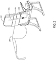
- the AR system renders 3D models 204 of various wire harness installation steps over an actual view of the wire harness installation environment (for example, an aircraft seat frame 202).
- the AR system locates the 3D models 204 in 3D space based on landmarks identified on the aircraft seat frame 202 in image streams from the incorporated cameras.
- a 3D model of the aircraft seat frame 202 defines proper locations 206 of the installed wire harness, allowing the 3D models 204 to be positioned and oriented with respect to the aircraft seat frame 3D model; the 3D models 204 are continuously re-rendered to accommodate the changes in position and orientation of the installer.
- the AR system may render detailed 3D model elements 208 detailing installation steps. For example, an animation showing a fixation process for securing the wire harness to the aircraft seat frame 202 may be rendered.
- the AR system may distinguish among a plurality of possible aircraft seat frames 202 based on certain identifiable characteristics / landmarks on each aircraft seat frame 202.
- Each aircraft seat frame 202 may require specific installation steps; upon identifying the aircraft seat frame 202 being used, the AR system my may utilize a specific set of 3D models 204 corresponding to installation steps for the specific aircraft seat frame 202.
- a processor receives 300 3D models of installation components, and receives 302 3D models of one or more installation environments corresponding to real world structures where an installer will actually install the installation components.
- landmarks are identified 304 that may be used to orient the 3D model of each installation environment with respect to a real-world analog via object recognition algorithms.
- the 3D models of installation components are each located and oriented 306 with respect to the identified landmarks.
- the processor receives 308 one or more installation steps, each corresponding to at least one of the 3D models of installation components as installed in a 3D models of one of the installation environments.
- the one or more installation steps may be hierarchical such that each requires a previous step to be completed.
- installation steps may be nested such that one or more of the installation steps may include higher granularity sub-steps.
- each installation step may be associated with a 3D animation of the installation step utilizing the corresponding 3D models of installation components with respect to the landmarks.
- Each installation component model corresponds to an installation step, the corresponding 3D models of installation components, any associated 3D animations, landmarks, and installation step completion criteria that may be identified object recognition algorithms such as identifying when a real-world installation component is substantially in the same position and orientation as the 3D model of the installation component.
- the AR system receives 400 one or more image streams during an installation process.
- An AR system processor identifies 402 one or more landmarks in each image stream corresponding to fixed points in an installation environment (such as an aircraft seat frame).
- the processor orients and locates 404 one or more installation component models relative to the landmarks; each installation component model corresponding to an installation step.
- the installation component model is then rendered 406 in an AR system display, potentially a stereoscopic display.
- the processor may determine 408 that an installation step is complete based on certain criteria associated with the installation component model, then render 406 a subsequent installation step. Alternatively, or in addition, the processor may receive 410 a request for additional detail and render 412 an interstitial model of an installation step with increased granularity or installation detail.
- Embodiments of the present disclosure may be utilized for electrical wire harness placement during an aircraft seat assembly process.
- the AR system displays a digital, holographic overlay of the wire harness in a set sequence onto the seat frame to indicate placement of the physical wires. This can be used for placement of wires and also for quality check / verification during assembly.
- the holographic overlay for each wire harness has its position defined for each component ensuring correct placement of wires, electrical boxes, and cable ties.
- components and the seat frame may be recorded at each installation step for quality verification.
- Embodiments of the present disclosure may be utilized for applications other than wire harness installation, such as other component installation processes, galley operations, and various crew training procedures.
- Artificial intelligence may be utilized in certain applications to identify the installation environment and completion of installation steps.
Landscapes
- Engineering & Computer Science (AREA)
- General Physics & Mathematics (AREA)
- Theoretical Computer Science (AREA)
- Physics & Mathematics (AREA)
- Business, Economics & Management (AREA)
- Computer Graphics (AREA)
- Software Systems (AREA)
- General Engineering & Computer Science (AREA)
- Computer Hardware Design (AREA)
- Entrepreneurship & Innovation (AREA)
- Educational Technology (AREA)
- Educational Administration (AREA)
- Multimedia (AREA)
- Processing Or Creating Images (AREA)
Abstract
Description
- Wire harness installation requires frequent, periodic reference to drawings or screens to visualize the installation. Often, the reference drawings are generalized to a single installation environment even though such environments are often divergent, for example various aircraft seat frames are different and not generalizable for wire frame installation. Furthermore, reference drawings cannot adequately represent the nuance of placement in 3D space. Even existing augmented reality (AR) mechanisms to assist with wire harness installation only place the reference documents within the scene of the installation.
- In one aspect, embodiments of the inventive concepts disclosed herein are directed to an AR system to assist with installation of wire harnesses. The AR system identifies landmarks in the installation environment and continuously orients 3D models of the wire harness components with reference to the landmarks in 3D space. The 3D models are rendered in an AR device to correspond to the placement in 3D space with respect to the landmarks.
- In a further aspect, the installation process is broken down into steps and sub-steps. An installer may install the wire harness according to predefined steps and be presented with higher granularity instructions upon request. The higher granularity sub-steps may include additional 3D models.
- It is to be understood that both the foregoing general description and the following detailed description are exemplary and explanatory only and should not restrict the scope of the claims. The accompanying drawings, which are incorporated in and constitute a part of the specification, illustrate exemplary embodiments of the inventive concepts disclosed herein and together with the general description, serve to explain the principles.
- The numerous advantages of the embodiments of the inventive concepts disclosed herein may be better understood by those skilled in the art by reference to the accompanying figures in which:
-
FIG. 1 shows a block diagram of an AR system according to an exemplary embodiment; -
FIG. 2 shows an environmental view of an AR system according to an exemplary embodiment; -
FIG. 3 shows a flowchart for a method for creating 3D model installation steps for an AR system according to an exemplary embodiment; and -
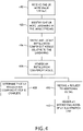
FIG. 4 shows a flowchart for a method for installing wire harnesses with an AR system according to an exemplary embodiment. - Before explaining at least one embodiment of the inventive concepts disclosed herein in detail, it is to be understood that the inventive concepts are not limited in their application to the details of construction and the arrangement of the components or steps or methodologies set forth in the following description or illustrated in the drawings. In the following detailed description of embodiments of the instant inventive concepts, numerous specific details are set forth in order to provide a more thorough understanding of the inventive concepts. However, it will be apparent to one of ordinary skill in the art having the benefit of the instant disclosure that the inventive concepts disclosed herein may be practiced without these specific details. In other instances, well-known features may not be described in detail to avoid unnecessarily complicating the instant disclosure. The inventive concepts disclosed herein are capable of other embodiments or of being practiced or carried out in various ways. Also, it is to be understood that the phraseology and terminology employed herein is for the purpose of description and should not be regarded as limiting.
- As used herein a letter following a reference numeral is intended to reference an embodiment of the feature or element that may be similar, but not necessarily identical, to a previously described element or feature bearing the same reference numeral (e.g., 1, 1a, 1b). Such shorthand notations are used for purposes of convenience only, and should not be construed to limit the inventive concepts disclosed herein in any way unless expressly stated to the contrary.
- Further, unless expressly stated to the contrary, "or" refers to an inclusive or and not to an exclusive or. For example, a condition A or B is satisfied by anyone of the following: A is true (or present) and B is false (or not present), A is false (or not present) and B is true (or present), and both A and B are true (or present).
- In addition, use of the "a" or "an" are employed to describe elements and components of embodiments of the instant inventive concepts. This is done merely for convenience and to give a general sense of the inventive concepts, and "a" and "an" are intended to include one or at least one and the singular also includes the plural unless it is obvious that it is meant otherwise.
- Finally, as used herein any reference to "one embodiment," or "some embodiments" means that a particular element, feature, structure, or characteristic described in connection with the embodiment is included in at least one embodiment of the inventive concepts disclosed herein. The appearances of the phrase "in some embodiments" in various places in the specification are not necessarily all referring to the same embodiment, and embodiments of the inventive concepts disclosed may include one or more of the features expressly described or inherently present herein, or any combination of sub-combination of two or more such features, along with any other features which may not necessarily be expressly described or inherently present in the instant disclosure.
- Broadly, embodiments of the inventive concepts disclosed herein are directed to an AR system to assist with installation of wire harnesses. The AR system identifies landmarks in the installation environment and continuously orients 3D models of the wire harness components with reference to the landmarks in 3D space. The 3D models are rendered in an AR device to correspond to the placement in 3D space with respect to the landmarks.
- Referring to
FIG. 1 , a block diagram of an AR system according to an exemplary embodiment is shown. The AR system includes aprocessor 100, memory 102 connected to theprocessor 100, one ormore cameras 104 connected to theprocessor 100, and one ormore displays 106 connected to theprocessor 100. The memory 102 stores non-transitory processor executable code for configuring theprocessor 100 to receive image streams from the one ormore cameras 104, process the images, and render overlay images on the one ormore displays 106. - During an exemplary installation processes, an installer using an AR device including the AR system may select an installation environment (a specific model of aircraft seat or aircraft seat frame) or the
processor 100 may determine the installation environment automatically via object recognition from the image streams and reference to a known database of installation environments stored in adata storage element 108 in data communication with theprocessor 100; for example, each aircraft seat frame may include features that identifiable via edge detection algorithms. Theprocessor 100 retrieves a 3D model of the installation environment including a plurality of identifiable landmarks of the installation environment. Theprocessor 100 identifies corresponding landmarks in the image streams and orients the 3D models based on those landmarks. 3D models may be directly derived from engineering models such as Jupiter Tessellation (JT) files. - The
processor 100 then retrieves stored 3D models corresponding to a sequence of installation steps of a wire harness in the installation environment. In at least one embodiment, theprocessor 100 defines a 3D space based on the location and orientation of the 3D model of the installation environment and continuously updates the installer's location and orientation in that 3D space based on changing landmark locations in the image streams. - The processor orients a
first installation step 3D model in the 3D space with respect to a known relation between thefirst installation step 3D model and the 3D model of the installation environment, and renders thefirst installation step 3D model as an overlay to the image streams on the one ormore displays 106. In at least one embodiment, such rendering may be stereoscopic to create a holographic type view of thefirst installation step 3D model in the installers actual view. - In at least one embodiment, the
processor 100 may determine that the first installation step is complete based on an object recognition algorithm operating on the image streams that determines an actual wire harness component occupies a space corresponding to thefirst installation step 3D model. Alternatively, theprocessor 100 may wait for confirmation from the installer that the first installation step is complete. Then theprocessor 100 de-renders thefirst installation step 3D model and iteratively performs the same process withsubsequent installation step 3D models until the installation process is complete. - In at least one embodiment, the
installation step 3D models may correspond to major installation step.Interstitial installation step 3D models may also be stored, corresponding to minor installation steps of higher instructional granularity. For example, major installation steps may correspond to wire harness placement points while interstitial installation steps may show actual fixation steps. - Referring to
FIG. 2 , an environmental view of an AR system according to an exemplary embodiment is shown. The AR system utilizes anAR device 200 having one or more incorporated cameras and one or more displays disposed in the field of view of an installer. The displays may be at least partially translucent or transparent, or may comprise projection elements disposed to project an image on a surface of theAR device 200 within the installers field of view. The AR system renders3D models 204 of various wire harness installation steps over an actual view of the wire harness installation environment (for example, an aircraft seat frame 202). - The AR system locates the
3D models 204 in 3D space based on landmarks identified on theaircraft seat frame 202 in image streams from the incorporated cameras. A 3D model of theaircraft seat frame 202 definesproper locations 206 of the installed wire harness, allowing the3D models 204 to be positioned and oriented with respect to theaircraft seat frame 3D model; the3D models 204 are continuously re-rendered to accommodate the changes in position and orientation of the installer. - The AR system may render detailed
3D model elements 208 detailing installation steps. For example, an animation showing a fixation process for securing the wire harness to theaircraft seat frame 202 may be rendered. - In at least one embodiment, the AR system may distinguish among a plurality of possible
aircraft seat frames 202 based on certain identifiable characteristics / landmarks on eachaircraft seat frame 202. Eachaircraft seat frame 202 may require specific installation steps; upon identifying theaircraft seat frame 202 being used, the AR system my may utilize a specific set of3D models 204 corresponding to installation steps for the specificaircraft seat frame 202. - Referring to
FIG. 3 , a flowchart for a method for creating 3D model installation steps for an AR system according to an exemplary embodiment is shown. A processor receives 300 3D models of installation components, and receives 302 3D models of one or more installation environments corresponding to real world structures where an installer will actually install the installation components. - Based on the 3D models of the installation environments, landmarks are identified 304 that may be used to orient the 3D model of each installation environment with respect to a real-world analog via object recognition algorithms. The 3D models of installation components are each located and oriented 306 with respect to the identified landmarks.
- The processor receives 308 one or more installation steps, each corresponding to at least one of the 3D models of installation components as installed in a 3D models of one of the installation environments. In at least one embodiment, the one or more installation steps may be hierarchical such that each requires a previous step to be completed. In at least one embodiment, installation steps may be nested such that one or more of the installation steps may include higher granularity sub-steps. In at least one embodiment, each installation step may be associated with a 3D animation of the installation step utilizing the corresponding 3D models of installation components with respect to the landmarks.
- Based on the installation steps, installation component models are created 310. Each installation component model corresponds to an installation step, the corresponding 3D models of installation components, any associated 3D animations, landmarks, and installation step completion criteria that may be identified object recognition algorithms such as identifying when a real-world installation component is substantially in the same position and orientation as the 3D model of the installation component.
- Referring to
FIG. 4 , a flowchart for a method for installing wire harnesses with an AR system according to an exemplary embodiment is shown. The AR system receives 400 one or more image streams during an installation process. An AR system processor identifies 402 one or more landmarks in each image stream corresponding to fixed points in an installation environment (such as an aircraft seat frame). - The processor orients and locates 404 one or more installation component models relative to the landmarks; each installation component model corresponding to an installation step. The installation component model is then rendered 406 in an AR system display, potentially a stereoscopic display.
- The processor may determine 408 that an installation step is complete based on certain criteria associated with the installation component model, then render 406 a subsequent installation step. Alternatively, or in addition, the processor may receive 410 a request for additional detail and render 412 an interstitial model of an installation step with increased granularity or installation detail.
- Embodiments of the present disclosure may be utilized for electrical wire harness placement during an aircraft seat assembly process. The AR system displays a digital, holographic overlay of the wire harness in a set sequence onto the seat frame to indicate placement of the physical wires. This can be used for placement of wires and also for quality check / verification during assembly. The holographic overlay for each wire harness has its position defined for each component ensuring correct placement of wires, electrical boxes, and cable ties. In at least one embodiment, components and the seat frame may be recorded at each installation step for quality verification.
- Embodiments of the present disclosure may be utilized for applications other than wire harness installation, such as other component installation processes, galley operations, and various crew training procedures.
- Artificial intelligence may be utilized in certain applications to identify the installation environment and completion of installation steps.
- It is believed that the inventive concepts disclosed herein and many of their attendant advantages will be understood by the foregoing description of embodiments of the inventive concepts disclosed, and it will be apparent that various changes may be made in the form, construction, and arrangement of the components thereof without departing from the broad scope of the inventive concepts disclosed herein or without sacrificing all of their material advantages; and individual features from various embodiments may be combined to arrive at other embodiments. The form herein before described being merely an explanatory embodiment thereof, it is the intention of the following claims to encompass and include such changes. Furthermore, any of the features disclosed in relation to any of the individual embodiments may be incorporated into any other embodiment.
Claims (15)
- A computer apparatus comprising:
at least one processor (100) in data communication with a memory (102) storing processor executable code for configuring the at least one processor to:receive (400) one or more image streams;identify (402) one or more landmarks in each image stream, the one or more landmarks each corresponding to a fixed point on an aircraft seat frame (202);orient and locate (404) a 3D component model with respect to the landmarks; andrender (406) an overlay of the 3D component model to appear at a real-world location of a correspond installation component during an installation step in a sequence of installation steps. - The computer apparatus of Claim 1, wherein the at least one processor is further configured to:determine (408) that the installation step is complete; andrender an overlay of a subsequent 3D component model to appear at a real-world location of a correspond installation component during a subsequent installation step in the sequence of installation steps.
- The computer apparatus of Claim 1 or 2, wherein the 3D component model comprises an installation animation specific to the installation step.
- The computer apparatus of any preceding Claim, wherein the at least one processor is further configured to:identify a type of aircraft seat frame based on the landmarks; andapply a 3D component model specific to the type of aircraft seat frame.
- The computer apparatus of any preceding Claim, wherein the at least one processor is further configured to:receive (410) a request from an installer for a detailed installation step; andrender (412) a high-detail 3D component model including more detailed installation instructions as compared to the corresponding 3D component model.
- The computer apparatus of any preceding Claim, wherein the at least one processor is further configured to continuously re-render the overlay to continuously correspond to the real-world location when an installer moves.
- A method comprising:receiving (400) one or more image streams from the one or more camera;identifying (402) one or more landmarks in each image stream, the one or more landmarks each corresponding to a fixed point on an aircraft seat frame;orienting and locating (404) a 3D component model with respect to the landmarks; andrendering (406) an overlay of the 3D component model on the one or more display devices to appear at a real-world location of a correspond installation component during an installation step in a sequence of installation steps.
- The method of Claim 7, further comprising:determining (408) that the installation step is complete; andrendering an overlay of a subsequent 3D component model to appear at a real-world location of a correspond installation component during a subsequent installation step in the sequence of installation steps.
- The method of Claim 7 or 8, wherein the 3D component model comprises an installation animation specific to the installation step.
- The method of Claim 7, 8 or 9, further comprising:identifying a type of aircraft seat frame based on the landmarks; andapplying a 3D component model specific to the type of aircraft seat frame.
- The method of any of Claims 7 to 10, further comprising:receiving (410) a request from an installer for a detailed installation step; andrendering (412) a high-detail 3D component model including more detailed installation instructions as compared to the corresponding 3D component model.
- The method of any of Claims 7 to 11, further comprising continuously re-rendering the overlay to continuously correspond to the real-world location when an installer moves.
- The method of any of Claims 7 to 12, wherein rendering the overlay comprises stereoscopic rendering.
- A system comprising:
one or more cameras (104);
one or more display devices (106) configured to overlay a rendered image onto a real-world scene; and the computer apparatus of any of claims 1 to 6, wherein the processor is configured to receive the one or more image streams from the one or more cameras. - The system of Claim 14, wherein the one or more display devices comprise a stereoscopic display device.
Applications Claiming Priority (1)
| Application Number | Priority Date | Filing Date | Title |
|---|---|---|---|
| US17/174,822 US11776420B2 (en) | 2021-02-12 | 2021-02-12 | Augmented reality in wire harness installation |
Publications (2)
| Publication Number | Publication Date |
|---|---|
| EP4044124A1 true EP4044124A1 (en) | 2022-08-17 |
| EP4044124B1 EP4044124B1 (en) | 2025-12-03 |
Family
ID=79317017
Family Applications (1)
| Application Number | Title | Priority Date | Filing Date |
|---|---|---|---|
| EP22151180.1A Active EP4044124B1 (en) | 2021-02-12 | 2022-01-12 | Augmented reality in wire harness installation |
Country Status (2)
| Country | Link |
|---|---|
| US (1) | US11776420B2 (en) |
| EP (1) | EP4044124B1 (en) |
Families Citing this family (1)
| Publication number | Priority date | Publication date | Assignee | Title |
|---|---|---|---|---|
| US20250245945A1 (en) * | 2024-01-31 | 2025-07-31 | Synopsys, Inc. | Extended reality-based visualization for information technology planning and installation |
Citations (3)
| Publication number | Priority date | Publication date | Assignee | Title |
|---|---|---|---|---|
| EP3483703A1 (en) * | 2017-11-09 | 2019-05-15 | The Boeing Company | Systems, methods, and tools for spatially-registering virtual content with physical environment in augmented reality platforms |
| US20190251747A1 (en) * | 2018-02-09 | 2019-08-15 | Paccar Inc | Systems and methods for providing augmented reality support for vehicle service operations |
| US20190266804A1 (en) * | 2018-02-23 | 2019-08-29 | Sap Se | Virtual prototyping and assembly validation |
Family Cites Families (25)
| Publication number | Priority date | Publication date | Assignee | Title |
|---|---|---|---|---|
| US6625299B1 (en) | 1998-04-08 | 2003-09-23 | Jeffrey Meisner | Augmented reality technology |
| US8749396B2 (en) * | 2011-08-25 | 2014-06-10 | Satorius Stedim Biotech Gmbh | Assembling method, monitoring method, communication method, augmented reality system and computer program product |
| US11205353B2 (en) | 2013-03-31 | 2021-12-21 | Ziota Technology Inc. | Method for assembling or repairing a connectorized electrical equipment in an environment |
| WO2015017242A1 (en) * | 2013-07-28 | 2015-02-05 | Deluca Michael J | Augmented reality based user interfacing |
| US10360729B2 (en) * | 2015-04-06 | 2019-07-23 | Scope Technologies Us Inc. | Methods and apparatus for augmented reality applications |
| US9589390B2 (en) * | 2015-05-13 | 2017-03-07 | The Boeing Company | Wire harness assembly |
| EP3104241B1 (en) * | 2015-06-12 | 2020-09-16 | Accenture Global Services Limited | An augmented reality method and system for measuring and/or manufacturing |
| SG10201913907YA (en) | 2016-03-30 | 2020-03-30 | Agency Science Tech & Res | Methods for providing task related information to a user, user assistance systems, and computer-readable media |
| CA3005051A1 (en) * | 2017-05-16 | 2018-11-16 | Michael J. Schuster | Augmented reality task identification and assistance in construction, remodeling, and manufacturing |
| US11132479B1 (en) * | 2017-12-29 | 2021-09-28 | II John Tyson | Augmented reality system for component assembly and archival baseline clone |
| WO2019156682A1 (en) | 2018-02-09 | 2019-08-15 | Yin David Wei Cheng | Systems and methods for providing augmented reality support for vehicle service operations |
| US11029671B1 (en) * | 2018-08-22 | 2021-06-08 | Automated Wiring Systems, LLC | Integrated wire harness batch production using augmented reality |
| EP3864678A4 (en) * | 2018-10-13 | 2022-07-06 | United Aircraft Technologies, Inc. | INTELLIGENT INTERCONNECTING CLAMP SYSTEM |
| WO2020113329A1 (en) | 2018-12-04 | 2020-06-11 | Ziota Technology Inc. | Augmented reality or virtual reality apparatus for producing connectorized equipment and managing the production thereof |
| US11443495B2 (en) * | 2018-12-31 | 2022-09-13 | Palo Alto Research Center Incorporated | Alignment- and orientation-based task assistance in an AR environment |
| US10943401B2 (en) * | 2019-02-01 | 2021-03-09 | International Business Machines Corporation | Active visual recognition in mobile augmented reality |
| US11593725B2 (en) * | 2019-04-16 | 2023-02-28 | At&T Intellectual Property I, L.P. | Gaze-based workflow adaptation |
| US10846899B2 (en) * | 2019-04-17 | 2020-11-24 | Honeywell International Inc. | Methods and systems for augmented reality safe visualization during performance of tasks |
| KR102447894B1 (en) * | 2019-07-11 | 2022-09-27 | 주식회사 경동나비엔 | Boiler installation cost calculation device and method |
| US11164396B2 (en) * | 2019-07-29 | 2021-11-02 | Dell Products L.P. | Servicing system with snapshot function |
| US10949671B2 (en) * | 2019-08-03 | 2021-03-16 | VIRNECT inc. | Augmented reality system capable of manipulating an augmented reality object and an augmented reality method using the same |
| US11127222B2 (en) * | 2019-08-16 | 2021-09-21 | MBTE Holdings Sweden AB | Augmented reality environment for technical data |
| WO2021236630A1 (en) * | 2020-05-18 | 2021-11-25 | Hyperframe Inc. | Construction visualization system and method |
| US11422380B2 (en) * | 2020-09-30 | 2022-08-23 | Snap Inc. | Eyewear including virtual scene with 3D frames |
| US11475645B2 (en) * | 2021-02-17 | 2022-10-18 | Verizon Patent And Licensing Inc. | Systems and methods for installing an item using augmented reality |
-
2021
- 2021-02-12 US US17/174,822 patent/US11776420B2/en active Active
-
2022
- 2022-01-12 EP EP22151180.1A patent/EP4044124B1/en active Active
Patent Citations (3)
| Publication number | Priority date | Publication date | Assignee | Title |
|---|---|---|---|---|
| EP3483703A1 (en) * | 2017-11-09 | 2019-05-15 | The Boeing Company | Systems, methods, and tools for spatially-registering virtual content with physical environment in augmented reality platforms |
| US20190251747A1 (en) * | 2018-02-09 | 2019-08-15 | Paccar Inc | Systems and methods for providing augmented reality support for vehicle service operations |
| US20190266804A1 (en) * | 2018-02-23 | 2019-08-29 | Sap Se | Virtual prototyping and assembly validation |
Non-Patent Citations (1)
| Title |
|---|
| JOSE MOLINEROS: "COMPUTER VISION AND AUGMENTED REALITY FOR GUIDING ASSEMBLY", 31 May 2002 (2002-05-31), XP055272043, Retrieved from the Internet <URL:https://etda.libraries.psu.edu/paper/5942/1209> [retrieved on 20160511] * |
Also Published As
| Publication number | Publication date |
|---|---|
| US20220262271A1 (en) | 2022-08-18 |
| US11776420B2 (en) | 2023-10-03 |
| EP4044124B1 (en) | 2025-12-03 |
Similar Documents
| Publication | Publication Date | Title |
|---|---|---|
| US10854006B2 (en) | AR-enabled labeling using aligned CAD models | |
| US10349033B2 (en) | Three-dimensional map generating and displaying apparatus and method | |
| Song et al. | End-to-end image stitching network via multi-homography estimation | |
| EP3379459A1 (en) | System and method for telecom inventory management | |
| CN112907620A (en) | Camera pose estimation method and device, readable storage medium and electronic equipment | |
| WO2018104563A3 (en) | Method and system for video-based positioning and mapping | |
| CN110502097B (en) | Motion control portal in virtual reality | |
| CN103718540B (en) | Method, user terminal and computer readable recording medium storing program for performing for generating panoramic picture | |
| US10572716B2 (en) | Processing uncertain content in a computer graphics system | |
| US9437034B1 (en) | Multiview texturing for three-dimensional models | |
| US11436755B2 (en) | Real-time pose estimation for unseen objects | |
| US9165397B2 (en) | Texture blending between view-dependent texture and base texture in a geographic information system | |
| AU2022215283B2 (en) | A method of training a machine learning algorithm to identify objects or activities in video surveillance data | |
| CN110235171A (en) | System and method for compensating the reflection in display equipment | |
| CN109656319B (en) | Method and equipment for presenting ground action auxiliary information | |
| US11100617B2 (en) | Deep learning method and apparatus for automatic upright rectification of virtual reality content | |
| EP4044124B1 (en) | Augmented reality in wire harness installation | |
| CN110232676B (en) | Installation state detection method, device, equipment and system of aircraft cable support | |
| CN109034214B (en) | Method and apparatus for generating a mark | |
| WO2025121207A1 (en) | Information processing device, information processing method, and program | |
| CN117592974B (en) | Meta universe-based device maintenance method and device, electronic device and readable medium | |
| US20120313945A1 (en) | System and method for adding a creative element to media | |
| EP3467807B1 (en) | Map information transmission device for transmitting objects for display superimposed on map, map display device, program, and method | |
| CN113674433B (en) | Mixed reality display method and system | |
| CN109214482A (en) | A kind of indoor orientation method, device, terminal device and storage medium |
Legal Events
| Date | Code | Title | Description |
|---|---|---|---|
| PUAI | Public reference made under article 153(3) epc to a published international application that has entered the european phase |
Free format text: ORIGINAL CODE: 0009012 |
|
| STAA | Information on the status of an ep patent application or granted ep patent |
Free format text: STATUS: THE APPLICATION HAS BEEN PUBLISHED |
|
| AK | Designated contracting states |
Kind code of ref document: A1 Designated state(s): AL AT BE BG CH CY CZ DE DK EE ES FI FR GB GR HR HU IE IS IT LI LT LU LV MC MK MT NL NO PL PT RO RS SE SI SK SM TR |
|
| STAA | Information on the status of an ep patent application or granted ep patent |
Free format text: STATUS: REQUEST FOR EXAMINATION WAS MADE |
|
| 17P | Request for examination filed |
Effective date: 20230215 |
|
| RBV | Designated contracting states (corrected) |
Designated state(s): AL AT BE BG CH CY CZ DE DK EE ES FI FR GB GR HR HU IE IS IT LI LT LU LV MC MK MT NL NO PL PT RO RS SE SI SK SM TR |
|
| P01 | Opt-out of the competence of the unified patent court (upc) registered |
Effective date: 20230922 |
|
| STAA | Information on the status of an ep patent application or granted ep patent |
Free format text: STATUS: EXAMINATION IS IN PROGRESS |
|
| 17Q | First examination report despatched |
Effective date: 20240514 |
|
| GRAP | Despatch of communication of intention to grant a patent |
Free format text: ORIGINAL CODE: EPIDOSNIGR1 |
|
| STAA | Information on the status of an ep patent application or granted ep patent |
Free format text: STATUS: GRANT OF PATENT IS INTENDED |
|
| INTG | Intention to grant announced |
Effective date: 20250626 |
|
| GRAS | Grant fee paid |
Free format text: ORIGINAL CODE: EPIDOSNIGR3 |
|
| GRAA | (expected) grant |
Free format text: ORIGINAL CODE: 0009210 |
|
| STAA | Information on the status of an ep patent application or granted ep patent |
Free format text: STATUS: THE PATENT HAS BEEN GRANTED |
|
| AK | Designated contracting states |
Kind code of ref document: B1 Designated state(s): AL AT BE BG CH CY CZ DE DK EE ES FI FR GB GR HR HU IE IS IT LI LT LU LV MC MK MT NL NO PL PT RO RS SE SI SK SM TR |
|
| REG | Reference to a national code |
Ref country code: CH Ref legal event code: F10 Free format text: ST27 STATUS EVENT CODE: U-0-0-F10-F00 (AS PROVIDED BY THE NATIONAL OFFICE) Effective date: 20251203 Ref country code: GB Ref legal event code: FG4D |
|
| REG | Reference to a national code |
Ref country code: DE Ref legal event code: R096 Ref document number: 602022025932 Country of ref document: DE |
|
| REG | Reference to a national code |
Ref country code: IE Ref legal event code: FG4D |
|
| REG | Reference to a national code |
Ref country code: NL Ref legal event code: MP Effective date: 20251203 |
|
| PG25 | Lapsed in a contracting state [announced via postgrant information from national office to epo] |
Ref country code: ES Free format text: LAPSE BECAUSE OF FAILURE TO SUBMIT A TRANSLATION OF THE DESCRIPTION OR TO PAY THE FEE WITHIN THE PRESCRIBED TIME-LIMIT Effective date: 20251203 |
|
| REG | Reference to a national code |
Ref country code: LT Ref legal event code: MG9D |
|
| PG25 | Lapsed in a contracting state [announced via postgrant information from national office to epo] |
Ref country code: NO Free format text: LAPSE BECAUSE OF FAILURE TO SUBMIT A TRANSLATION OF THE DESCRIPTION OR TO PAY THE FEE WITHIN THE PRESCRIBED TIME-LIMIT Effective date: 20260303 |
|
| PGFP | Annual fee paid to national office [announced via postgrant information from national office to epo] |
Ref country code: DE Payment date: 20251217 Year of fee payment: 5 |
|
| PG25 | Lapsed in a contracting state [announced via postgrant information from national office to epo] |
Ref country code: HR Free format text: LAPSE BECAUSE OF FAILURE TO SUBMIT A TRANSLATION OF THE DESCRIPTION OR TO PAY THE FEE WITHIN THE PRESCRIBED TIME-LIMIT Effective date: 20251203 Ref country code: FI Free format text: LAPSE BECAUSE OF FAILURE TO SUBMIT A TRANSLATION OF THE DESCRIPTION OR TO PAY THE FEE WITHIN THE PRESCRIBED TIME-LIMIT Effective date: 20251203 |
|
| PGFP | Annual fee paid to national office [announced via postgrant information from national office to epo] |
Ref country code: AT Payment date: 20260301 Year of fee payment: 5 |
|
| PG25 | Lapsed in a contracting state [announced via postgrant information from national office to epo] |
Ref country code: RS Free format text: LAPSE BECAUSE OF FAILURE TO SUBMIT A TRANSLATION OF THE DESCRIPTION OR TO PAY THE FEE WITHIN THE PRESCRIBED TIME-LIMIT Effective date: 20260303 |
|
| PG25 | Lapsed in a contracting state [announced via postgrant information from national office to epo] |
Ref country code: PL Free format text: LAPSE BECAUSE OF FAILURE TO SUBMIT A TRANSLATION OF THE DESCRIPTION OR TO PAY THE FEE WITHIN THE PRESCRIBED TIME-LIMIT Effective date: 20251203 |
|
| PG25 | Lapsed in a contracting state [announced via postgrant information from national office to epo] |
Ref country code: LV Free format text: LAPSE BECAUSE OF FAILURE TO SUBMIT A TRANSLATION OF THE DESCRIPTION OR TO PAY THE FEE WITHIN THE PRESCRIBED TIME-LIMIT Effective date: 20251203 |
|
| PG25 | Lapsed in a contracting state [announced via postgrant information from national office to epo] |
Ref country code: BG Free format text: LAPSE BECAUSE OF FAILURE TO SUBMIT A TRANSLATION OF THE DESCRIPTION OR TO PAY THE FEE WITHIN THE PRESCRIBED TIME-LIMIT Effective date: 20251203 |
|
| REG | Reference to a national code |
Ref country code: AT Ref legal event code: MK05 Ref document number: 1864540 Country of ref document: AT Kind code of ref document: T Effective date: 20251203 |
|
| PG25 | Lapsed in a contracting state [announced via postgrant information from national office to epo] |
Ref country code: NL Free format text: LAPSE BECAUSE OF FAILURE TO SUBMIT A TRANSLATION OF THE DESCRIPTION OR TO PAY THE FEE WITHIN THE PRESCRIBED TIME-LIMIT Effective date: 20251203 |
|
| PG25 | Lapsed in a contracting state [announced via postgrant information from national office to epo] |
Ref country code: LT Free format text: LAPSE BECAUSE OF FAILURE TO SUBMIT A TRANSLATION OF THE DESCRIPTION OR TO PAY THE FEE WITHIN THE PRESCRIBED TIME-LIMIT Effective date: 20251203 |
|
| PG25 | Lapsed in a contracting state [announced via postgrant information from national office to epo] |
Ref country code: SM Free format text: LAPSE BECAUSE OF FAILURE TO SUBMIT A TRANSLATION OF THE DESCRIPTION OR TO PAY THE FEE WITHIN THE PRESCRIBED TIME-LIMIT Effective date: 20251203 |
|
| PG25 | Lapsed in a contracting state [announced via postgrant information from national office to epo] |
Ref country code: IT Free format text: LAPSE BECAUSE OF FAILURE TO SUBMIT A TRANSLATION OF THE DESCRIPTION OR TO PAY THE FEE WITHIN THE PRESCRIBED TIME-LIMIT Effective date: 20251203 |
|
| PG25 | Lapsed in a contracting state [announced via postgrant information from national office to epo] |
Ref country code: AT Free format text: LAPSE BECAUSE OF FAILURE TO SUBMIT A TRANSLATION OF THE DESCRIPTION OR TO PAY THE FEE WITHIN THE PRESCRIBED TIME-LIMIT Effective date: 20251203 |
|
| PG25 | Lapsed in a contracting state [announced via postgrant information from national office to epo] |
Ref country code: EE Free format text: LAPSE BECAUSE OF FAILURE TO SUBMIT A TRANSLATION OF THE DESCRIPTION OR TO PAY THE FEE WITHIN THE PRESCRIBED TIME-LIMIT Effective date: 20251203 |
|
| PG25 | Lapsed in a contracting state [announced via postgrant information from national office to epo] |
Ref country code: IS Free format text: LAPSE BECAUSE OF FAILURE TO SUBMIT A TRANSLATION OF THE DESCRIPTION OR TO PAY THE FEE WITHIN THE PRESCRIBED TIME-LIMIT Effective date: 20260403 Ref country code: PT Free format text: LAPSE BECAUSE OF FAILURE TO SUBMIT A TRANSLATION OF THE DESCRIPTION OR TO PAY THE FEE WITHIN THE PRESCRIBED TIME-LIMIT Effective date: 20260406 |
|
| PG25 | Lapsed in a contracting state [announced via postgrant information from national office to epo] |
Ref country code: CZ Free format text: LAPSE BECAUSE OF FAILURE TO SUBMIT A TRANSLATION OF THE DESCRIPTION OR TO PAY THE FEE WITHIN THE PRESCRIBED TIME-LIMIT Effective date: 20251203 |
|
| PG25 | Lapsed in a contracting state [announced via postgrant information from national office to epo] |
Ref country code: SK Free format text: LAPSE BECAUSE OF FAILURE TO SUBMIT A TRANSLATION OF THE DESCRIPTION OR TO PAY THE FEE WITHIN THE PRESCRIBED TIME-LIMIT Effective date: 20251203 |
|
| PG25 | Lapsed in a contracting state [announced via postgrant information from national office to epo] |
Ref country code: SE Free format text: LAPSE BECAUSE OF FAILURE TO SUBMIT A TRANSLATION OF THE DESCRIPTION OR TO PAY THE FEE WITHIN THE PRESCRIBED TIME-LIMIT Effective date: 20251203 |