EP4044080A1 - Work assistance server, work assistance method, and work assistance system - Google Patents
Work assistance server, work assistance method, and work assistance system Download PDFInfo
- Publication number
- EP4044080A1 EP4044080A1 EP20893592.4A EP20893592A EP4044080A1 EP 4044080 A1 EP4044080 A1 EP 4044080A1 EP 20893592 A EP20893592 A EP 20893592A EP 4044080 A1 EP4044080 A1 EP 4044080A1
- Authority
- EP
- European Patent Office
- Prior art keywords
- work
- designated
- information
- client
- assist
- Prior art date
- Legal status (The legal status is an assumption and is not a legal conclusion. Google has not performed a legal analysis and makes no representation as to the accuracy of the status listed.)
- Granted
Links
Images




Classifications
-
- G—PHYSICS
- G06—COMPUTING OR CALCULATING; COUNTING
- G06Q—INFORMATION AND COMMUNICATION TECHNOLOGY [ICT] SPECIALLY ADAPTED FOR ADMINISTRATIVE, COMMERCIAL, FINANCIAL, MANAGERIAL OR SUPERVISORY PURPOSES; SYSTEMS OR METHODS SPECIALLY ADAPTED FOR ADMINISTRATIVE, COMMERCIAL, FINANCIAL, MANAGERIAL OR SUPERVISORY PURPOSES, NOT OTHERWISE PROVIDED FOR
- G06Q10/00—Administration; Management
- G06Q10/06—Resources, workflows, human or project management; Enterprise or organisation planning; Enterprise or organisation modelling
- G06Q10/063—Operations research, analysis or management
-
- G—PHYSICS
- G06—COMPUTING OR CALCULATING; COUNTING
- G06Q—INFORMATION AND COMMUNICATION TECHNOLOGY [ICT] SPECIALLY ADAPTED FOR ADMINISTRATIVE, COMMERCIAL, FINANCIAL, MANAGERIAL OR SUPERVISORY PURPOSES; SYSTEMS OR METHODS SPECIALLY ADAPTED FOR ADMINISTRATIVE, COMMERCIAL, FINANCIAL, MANAGERIAL OR SUPERVISORY PURPOSES, NOT OTHERWISE PROVIDED FOR
- G06Q10/00—Administration; Management
- G06Q10/06—Resources, workflows, human or project management; Enterprise or organisation planning; Enterprise or organisation modelling
- G06Q10/063—Operations research, analysis or management
- G06Q10/0631—Resource planning, allocation, distributing or scheduling for enterprises or organisations
- G06Q10/06316—Sequencing of tasks or work
-
- E—FIXED CONSTRUCTIONS
- E02—HYDRAULIC ENGINEERING; FOUNDATIONS; SOIL SHIFTING
- E02F—DREDGING; SOIL-SHIFTING
- E02F9/00—Component parts of dredgers or soil-shifting machines, not restricted to one of the kinds covered by groups E02F3/00 - E02F7/00
- E02F9/20—Drives; Control devices
- E02F9/2025—Particular purposes of control systems not otherwise provided for
- E02F9/205—Remotely operated machines, e.g. unmanned vehicles
-
- E—FIXED CONSTRUCTIONS
- E02—HYDRAULIC ENGINEERING; FOUNDATIONS; SOIL SHIFTING
- E02F—DREDGING; SOIL-SHIFTING
- E02F9/00—Component parts of dredgers or soil-shifting machines, not restricted to one of the kinds covered by groups E02F3/00 - E02F7/00
- E02F9/26—Indicating devices
- E02F9/261—Surveying the work-site to be treated
-
- G—PHYSICS
- G06—COMPUTING OR CALCULATING; COUNTING
- G06Q—INFORMATION AND COMMUNICATION TECHNOLOGY [ICT] SPECIALLY ADAPTED FOR ADMINISTRATIVE, COMMERCIAL, FINANCIAL, MANAGERIAL OR SUPERVISORY PURPOSES; SYSTEMS OR METHODS SPECIALLY ADAPTED FOR ADMINISTRATIVE, COMMERCIAL, FINANCIAL, MANAGERIAL OR SUPERVISORY PURPOSES, NOT OTHERWISE PROVIDED FOR
- G06Q10/00—Administration; Management
- G06Q10/06—Resources, workflows, human or project management; Enterprise or organisation planning; Enterprise or organisation modelling
-
- G—PHYSICS
- G06—COMPUTING OR CALCULATING; COUNTING
- G06Q—INFORMATION AND COMMUNICATION TECHNOLOGY [ICT] SPECIALLY ADAPTED FOR ADMINISTRATIVE, COMMERCIAL, FINANCIAL, MANAGERIAL OR SUPERVISORY PURPOSES; SYSTEMS OR METHODS SPECIALLY ADAPTED FOR ADMINISTRATIVE, COMMERCIAL, FINANCIAL, MANAGERIAL OR SUPERVISORY PURPOSES, NOT OTHERWISE PROVIDED FOR
- G06Q50/00—Information and communication technology [ICT] specially adapted for implementation of business processes of specific business sectors, e.g. utilities or tourism
- G06Q50/08—Construction
Definitions
- the present invention relates to a work assist server to assist a worker in performing work by use of a work machine, through communication with a client assigned to the worker of the work machine.
- Patent Literature 1 There has been proposed a technology of grasping a three-dimensional shape of a construction work site, and accurately informing a construction equipment operator of a relation between a finishing stake and a current status, a travelable range, a dangerous range and the like (see Patent Literature 1, for example). Specifically, distance images obtained from stereo cameras arranged in separate places, respectively, are integrated to generate three-dimensional model data of the construction work site. Then, an image of the construction work site seen from a virtual perspective designated by the operator of the construction equipment is drawn based on the three-dimensional model data and displayed at a driving seat of the construction equipment.
- Patent Literature 1 Japanese Patent Laid-Open No. 2003-333590
- an object of the present invention is to provide a server and a system which enable a worker of a work machine to intuitively recognize work contents and the like to be performed using the work machine in each of a plurality of work locations.
- the present invention relates to a work assist server to assist a worker in performing work by use of a work machine, by communication with a client assigned to the worker of the work machine.
- the work assist server of the present invention comprises a database which stores and holds, as work information, a plurality of combinations of work locations, work periods and work contents, a first assist processing element which recognizes a designated position depending on a designated operation through an input interface of the client, based on the communication with the client, and which searches the database for the work information fitting the designated position as designated work information, and a second assist processing element which causes an output interface of the client to output a work environment image showing a position of a designated work location included in the designated work information searched by the first assist processing element, and information about at least one of a designated work period and a designated work content included in the designated work information, based on the communication with the client.
- a work assist system of the present invention comprises the work assist server, and the client.
- the output interface of the client in response to the designated operation through the input interface of the client, the output interface of the client outputs the work environment image showing the position of the designated work location, and the information about at least one of the designated work period and the designated work content.
- the designated work location, the designated work period and the designated work content are included in the designated work information that is work information fitting the designated position depending on the designated operation among a plurality of pieces of work information registered in the database. Consequently, the worker of the work machine can recognize outline of the work to be performed using the work machine, which fits the designated position, from the work environment image, and the information about at least one of the designated work period and the designated work content.
- a work assist system as an embodiment of the present invention shown in FIG. 1 includes a work assist server 10, and a remote operation device 20 to remotely operate a work machine 40.
- the work assist server 10, the remote operation device 20, the work machine 40 and a managing client 60 are configured to be mutually network communicable.
- the work assist server 10 comprises a database 102, a first assist processing element 121, and a second assist processing element 122.
- the database 102 stores and holds, as work information, a plurality of combinations of work locations, work periods and work contents.
- the database 102 may include a database server separate from the work assist server 10.
- Each assist processing element includes an arithmetic processing unit (a single core processor or a multi-core processor or a processor core included in the multi-core processor) and reads required data and software from a storage device such as a memory and executes after-mentioned arithmetic processing for the data as a target in accordance with the software.
- the remote operation device 20 constituting a client comprises a remote control device 200, a remote input interface 210, and a remote output interface 220.
- the remote control device 200 includes an arithmetic processing unit (a single core processor or a multi-core processor or a processor core included in the multi-core processor) and reads required data and software from a storage device such as a memory and executes arithmetic processing for the data as a target in accordance with the software.
- the remote input interface 210 comprises a remote operation mechanism 211.
- the remote output interface 220 comprises an image output device 221 and remote wireless communication equipment 222.
- the remote operation mechanism 211 includes an operation device for traveling, an operation device for turning, an operation device for boom, an operation device for arm, and an operation device for bucket.
- Each operation device includes operation levers receiving a rotating operation.
- the operation levers (travel levers) for the operation device for traveling are operated to move a lower traveling body 410 of the work machine 40.
- the travel levers may also serve as travel pedals.
- the operation lever (turn lever) of the operation device for turning is operated to move a hydraulic swing motor included in a turning mechanism 430 of the work machine 40.
- the operation lever (boom lever) of the operation device for boom is operated to move a boom cylinder 442 of the work machine 40.
- the operation lever (arm lever) of the operation device for arm is operated to move an arm cylinder 444 of the work machine 40.
- the operation lever (bucket lever) of the operation device for bucket is operated to move a bucket cylinder 446 of the work machine 40.
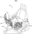
- the respective operation levers included in the remote operation mechanism 211 are arranged around a seat St on which an operator sits as shown in FIG. 2 , for example.
- the seat St has such a form as in a high back chair with armrests and may have any form on which a remote operator OP2 can sit, such as a form of a low back chair without a headrest or a form of a chair without a backrest.
- a pair of left and right travel levers 2110 corresponding to left and right crawlers are arranged laterally in a left-right direction.
- One operation lever may serve as a plurality of operation levers.
- a right-side operation lever 2111 provided in front of a right frame of the seat St shown in FIG. 2 may function as the boom lever when being operated in a front-rear direction and function as the bucket lever when being operated in a left-right direction.
- a left-side operation lever 2112 provided in front of a left frame of the seat St shown in FIG. 2 may function as the arm lever when being operated in the front-rear direction and function as the turn lever when being operated in the left-right direction.
- a lever pattern may be arbitrarily changed depending on an operator's operation instruction.
- the image output device 221 includes a diagonally right forward image output device 2211, a front image output device 2212 and a diagonally left forward image output device 2213 arranged diagonally forward to the right of the seat St, in front of the seat, and diagonally forward to the left of the seat, respectively.
- the image output devices 2211 to 2213 may further comprise a speaker (voice output device).
- the work machine 40 comprises an actual machine control device 400, an actual machine input interface 410, an actual machine output interface 420, and a working mechanism 440.
- the actual machine control device 400 includes an arithmetic processing unit (a single core processor or a multi-core processor or a processor core included in the multi-core processor) and reads required data and software from a storage device such as a memory and executes arithmetic processing for the data as a target in accordance with the software.
- arithmetic processing unit a single core processor or a multi-core processor or a processor core included in the multi-core processor
- the work machine 40 is, for example, a crawler shovel (construction machine), and comprises the crawler lower traveling body 410, and an upper turning body 420 rotatably mounted on the lower traveling body 410 via the turning mechanism 430 as shown in FIG. 3 .
- a cab (driver's cab) 424 is provided in a front left part of the upper turning body 420.
- a work attachment 440 is provided in a front center part of the upper turning body 420.
- the actual machine input interface 410 comprises an actual machine operation mechanism 411 and an imaging device 412.
- the actual machine operation mechanism 411 comprises a plurality of operation levers arranged around a seat disposed inside the cab 424 in the same manner as in the remote operation mechanism 211.
- a drive mechanism or a robot which receives a signal depending on an operation mode of a remote operation lever and moves an actual machine operation lever based on the received signal is provided in the cab 424.
- the imaging device 412 is installed, for example, inside the cab 424, and images an environment including at least a part of the working mechanism 440 through a front window of the cab 424.
- the actual machine output interface 420 comprises actual machine wireless communication equipment 422.
- the work attachment 440 as the working mechanism comprises a boom 441 mounted on the upper turning body 420 such that the boom can be undulated, an arm 443 rotatably coupled to a tip end of the boom 441, and a bucket 445 rotatably coupled to a tip end of the arm 443.
- the boom cylinder 442, the arm cylinder 444 and the bucket cylinder 446, each of which is configured with a telescopic hydraulic cylinder, are attached to the work attachment 440.
- the boom cylinder 442 is interposed between the boom 441 and the upper turning body 420 to receive supply of hydraulic oil and extend and retract, thereby rotating the boom 441 in an undulating direction.
- the arm cylinder 444 is interposed between the arm 443 and the boom 441 to receive the supply of hydraulic oil and extend and retract, thereby rotating the arm 443 to the boom 441 about a horizontal axis.
- the bucket cylinder 446 is interposed between the bucket 445 and the arm 443 to receive the supply of hydraulic oil and extend and retract, thereby rotating the bucket 445 to the arm 443 about the horizontal axis.
- the managing client 60 is a terminal device such as a smartphone or a tablet terminal, and comprises a control device 600, a managing input interface 610, and a managing output interface 620.
- the control device 600 includes an arithmetic processing unit (a single core processor or a multi-core processor or a processor core included in the multi-core processor) and reads required data and software from a storage device such as a memory and executes arithmetic processing for the data as a target in accordance with the software.
- arithmetic processing unit a single core processor or a multi-core processor or a processor core included in the multi-core processor
- the managing input interface 610 includes a button, a switch or the like of a touch panel.
- the managing output interface 620 comprises an image output device, and wireless communication equipment.
- the recognizing is concept including processing to prepare information in any form available for subsequent processing, such as receiving of the information, reading or retrieving of the information from the storage device or the like, writing (storing and holding) or registering of the information in the storage device or the like, presuming, determining, identifying, measuring, predicting or the like of the information by executing arithmetic processing of an output signal of the sensor and/or basic information according to predetermined algorithm, and the like.
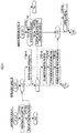
- a manager inputs work information to be newly registered in the database 102 or a change content of registered work information, through the managing input interface 610 ( FIG. 4 /STEP610).
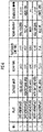
- the work information includes a plurality of combinations of work locations, work periods and work contents.
- the work location may be designated by being divided into a plurality of levels of areas. For example, as shown in FIG. 6 , "the work location” may be designated by a rough work location (an east workplace, a south workplace or the like) and a detailed work location (a gravel area, a coarse sand area or the like).
- the work period may be designated by start time (9:00, 9:15 or the like) and end time (9:15, 9:35 or the like) of the work period.
- the work content may be designated by a type of work (soil loading, pile-up or the like) and a work goal ( ⁇ m 3 (cubic meters), until time or the like).
- wireless communication equipment included in the managing output interface 620 transmits new work information or a change content of existing work information to the work assist server 10 ( FIG. 4 /STEP620).
- the new work information in a case where the new work information or the change content of the existing work information is recognized based on communication with the managing client 60 ( FIG. 4 /C10), the new work information is registered in the database 102, or the content of the work information registered in the database 102 is changed ( FIG. 4 /STEP102).
- the remote operation device 20 it is determined whether there is a first designated operation through the remote input interface 210 by an operator OP ( FIG. 4 /STEP202).
- the first designated operation is, for example, an operation of a button or an operation lever included in the remote input interface 210 or the remote operation mechanism 211.
- the determination result is negative (NO in FIG. 4 /STEP202)
- processing of and after the determination as to whether there is the first designated operation is repeated.
- a designated work information request is transmitted to the work assist server 10 through the remote wireless communication equipment 222 ( FIG. 4 /STEP204).
- the request includes information that can specify a designated position depending on the first designated operation.
- a representative position of an area designated by the first designated operation in the remote input interface 210 may be specified as the designated position.
- a position of the work machine 40 operated or scheduled to be operated by the remote operation device 20 at time of the first designated operation, the position of the work machine 40 being measured by a positioning function by use of a GPS or the like may be specified as the designated position.
- a position of the mobile terminal at time of a first operation, the position being measured by the positioning function by use of the GPS or the like may be specified as the designated position.
- the first assist processing element 121 recognizes the designated position ( FIG. 4 /STEP104).
- the first assist processing element 121 searches the database 102 for work information fitting the designated position as designated work information ( FIG. 4 /STEP106). For example, in a case where the representative position of the area designated by the operator is recognized as the designated position, the work information about work scheduled to be performed at current time or at and after designated time in the work location included in the area may be searched as the designated work information. "The designated time" may be set through the remote input interface 210 by the operator OP.
- the designated position work information about work to be performed in a work location at a distance from the current position of the work machine 40 being equal to and less than a designated distance is searched as the designated work information.
- the designated distance may be constant or may change, for example, to a distance at which the work machine 40 can move from the current time by start time of the work period.
- the designated distance may be a distance at which the operator OP carrying the mobile terminal can move to the current position of the work machine 40.
- the work information about the work that can be performed may be searched as the designated work information in view of numerous factors of the remotely operated or actually operated work machine 40.
- the second assist processing element 122 transmits the designated work information to the remote operation device 20 (first client) ( FIG. 4 /STEP108).
- the remote control device 200 causes the image output device 221 to output a work environment image showing a position of a designated work location and information about a designated work period and designated work content included in the designated work information ( FIG. 4 /STEP206).
- the image output device 221 outputs a bird's eye image or a two-dimensional map of a work site showing a position of next work location Q2 in addition to a position of present work location Q1 where the work is performed using the work machine 40.
- This is the result of searching the database 102 for a plurality of pieces of designated work information that are continuous in time series. Also, as information about remaining time of the present work period and a present work content, a message "please pile up for remaining 5 minutes" is outputted. Furthermore, as information about the next work location and start time of next work period, a message "please move to south workplace gravel area by 9:50" is outputted.
- the message can be added and updated as at least part of the work information in the managing client 60 through an operation of the managing input interface 610.
- the work environment image may be outputted in the image output device included in the managing output interface 620, and the work information may be registered or updated on time through the touch panel and a touch keyboard included in the managing input interface 610.
- an environment image showing appearance before the work machine 40 in the work site, a position of a local work location Q0 in the work site and additionally, a message of "please pile up soil here" concerning the work content may be outputted in the image output device 221.
- the message can be added and updated as at least part of the work information in the managing client 60 through the operation of the managing input interface 610.
- the remote operation device 20 it is determined whether there is a second designated operation through the remote input interface 210 by the operator OP ( FIG. 5 /STEP208).
- the second designated operation is, for example, an operation of tapping or the like in the remote input interface 210 to designate the work machine 40 intended to be remotely operated by the operator OP in the bird's eye work environment image (see FIG. 7A ).
- the determination result is negative (NO in FIG. 5 /STEP208)
- processing of and after the determination as to whether there is the second designated operation is repeated.
- an environment confirmation request is transmitted to the work assist server 10 through the remote wireless communication equipment 222 ( FIG. 5 /STEP210).
- the first assist processing element 121 transmits the environment confirmation request to the corresponding work machine 40 ( FIG. 5 /C12).
- the actual machine control device 400 obtains a captured image through the imaging device 412 ( FIG. 5 /STEP402).
- the actual machine control device 400 transmits captured image data representing the captured image to the work assist server 10 through the actual machine wireless communication equipment 422 ( FIG. 5 /STEP404).
- environment image data data representing all or part of the captured image itself or a simulated environment image generated based on this all or part of the captured image
- the remote operation device 20 FIG. 5 /STEP110
- the environment image depending on the environment image data is outputted in the image output device 221 ( FIG. 5 /STEP212). Consequently, for example, the environment image including the boom 441, the arm 443, the bucket 445 and the arm cylinder 444 that are some parts of the work attachment 440 as the working mechanism is displayed in each of the image output device 221 and a second image output device 221 (see FIG. 7B ).
- the remote control device 200 recognizes an operation mode of the remote operation mechanism 211 ( FIG. 5 /STEP214), and a remote operation command depending on the operation mode is transmitted to the work assist server 10 through the remote wireless communication equipment 222 ( FIG. 5 /STEP216).
- the first assist processing element 121 transmits the remote operation command to the work machine 40 ( FIG. 5 /C14).
- an operation of the work attachment 440 or the like is controlled ( FIG. 5 /STEP406). For example, work of scooping soil before the work machine 40 with the bucket 445 and rotating the upper turning body 420 to drop the soil from the bucket 445 is executed.
- the remote output interface 220 of the remote operation device 20 outputs the work environment image showing the positions of the designated work locations Q1 and Q2, and the information about at least one of the designated work period and the designated work content (see FIG. 4 /STEP after YES in STEP202 to STEP206, and FIG. 7A and 7B ).
- the designated work location, the designated work period and the designated work content are included in the designated work information that is work information fitting the designated position depending on the first designated operation among a plurality of pieces of work information registered in the database 102. Consequently, the operator OP (worker) of the work machine can recognize outline of the work to be performed using the work machine 40, which fits the designated position, from the work environment image, and the information about at least one of the designated work period and the designated work content.
- the work environment image showing the positions of the plurality of designated work locations Q1 and Q2 included in the plurality of pieces of designated work information, respectively, continuous in time series, and the information about at least one of the designated work period and the designated work content included in at least one piece of designated work information among the plurality of pieces of designated work information are outputted in the remote output interface 220 (see FIG. 7A ).
- the work environment image allows the worker to recognize the position of the work location (designated work location) of each of a plurality of works to be performed continuously in time series by the operator OP (worker) remotely operating or actually operating the common or different work machine 40.
- the information about the work period (designated work period) and the work content (designated work content) concerning at least one work among the plurality of works can be recognized by the worker.
- the first assist processing element 121 recognizes a current position of the work machine 40 as the designated position, based on communication with the client such as the remote operation device 20 or the work machine 40 cooperating with the client, and searches the database 102 for the work information of the position of the work location which matches the designated position, as one piece of designated work information among the plurality of pieces of designated work information. Consequently, outlines of the present work being performed by the worker using the work machine 40, and additionally, the work to be performed from next time by the worker using the same or different work machine 40 can be recognized.
- the first assist processing element 121 recognizes, as designated time, time when there is the designated operation through the input interface of the client or time set by the designated operation, based on the communication with the client of the remote operation device 20 or the like, and searches the database 102 for the work information fitting the designated time in addition to the designated position, as the designated work information. Consequently, the worker of the work machine can recognize the outline of the work to be performed using the work machine 40, which fits the designated time in addition to the designated position, from the work environment image, and the information about at least one of the designated work period and the designated work content.
- the first assist processing element 121 recognizes at least one of new work information and the change content of the work information stored and held in the database 102, which are inputted through the managing input interface 610 of the managing client 60, based on the communication with the managing client 60, and causes the database 102 to store and hold at least one of the new work information and the work information in which the change content is reflected.
- a work manager may register, in the database 102, new work information inputted using the managing client 60 and work information obtained after changing at least a part of the content of the work information registered in the database 102. Consequently, the worker of the work machine 40 can recognize the outline of the work to be performed using the work machine 40 as scheduled or intended by the work manager, from the work environment image outputted in the output interface of the client such as the remote operation device 20, and the information about at least one of the designated work period and the designated work content.
- the work assist server 10 is configured with one or more servers separate from each of the remote operation device 20, the work machine 40 and the managing client 60 (see FIG. 1 ), and as another embodiment, however, the work assist server 10 may be a constituent element of the remote operation device 20, the work machine 40 or the managing client 60.
- Each of the respective constituent elements 110, 121 and 122 of the work assist server 10 may be a constituent element of each of two or more of the remote operation device 20, the work machine 40 and the managing client 60 which are mutually communicable.
Landscapes
- Business, Economics & Management (AREA)
- Engineering & Computer Science (AREA)
- Human Resources & Organizations (AREA)
- Economics (AREA)
- Strategic Management (AREA)
- Entrepreneurship & Innovation (AREA)
- Tourism & Hospitality (AREA)
- Physics & Mathematics (AREA)
- Theoretical Computer Science (AREA)
- Marketing (AREA)
- General Physics & Mathematics (AREA)
- General Business, Economics & Management (AREA)
- Quality & Reliability (AREA)
- Development Economics (AREA)
- Game Theory and Decision Science (AREA)
- Operations Research (AREA)
- Educational Administration (AREA)
- General Engineering & Computer Science (AREA)
- Civil Engineering (AREA)
- Mining & Mineral Resources (AREA)
- Structural Engineering (AREA)
- Health & Medical Sciences (AREA)
- General Health & Medical Sciences (AREA)
- Primary Health Care (AREA)
- Operation Control Of Excavators (AREA)
- Management, Administration, Business Operations System, And Electronic Commerce (AREA)
Abstract
Description
- The present invention relates to a work assist server to assist a worker in performing work by use of a work machine, through communication with a client assigned to the worker of the work machine.
- There has been proposed a technology of grasping a three-dimensional shape of a construction work site, and accurately informing a construction equipment operator of a relation between a finishing stake and a current status, a travelable range, a dangerous range and the like (see
Patent Literature 1, for example). Specifically, distance images obtained from stereo cameras arranged in separate places, respectively, are integrated to generate three-dimensional model data of the construction work site. Then, an image of the construction work site seen from a virtual perspective designated by the operator of the construction equipment is drawn based on the three-dimensional model data and displayed at a driving seat of the construction equipment. - Patent Literature 1:
Japanese Patent Laid-Open No. 2003-333590 - In a case where a worker performs work by use of one or more work machines in each of a plurality of work locations that are away from one another and in each of different time zones, it is preferable that work contents and the like to be performed can be grasped for smoothly performing the work.
- To solve the problem, an object of the present invention is to provide a server and a system which enable a worker of a work machine to intuitively recognize work contents and the like to be performed using the work machine in each of a plurality of work locations.
- The present invention relates to a work assist server to assist a worker in performing work by use of a work machine, by communication with a client assigned to the worker of the work machine.
- The work assist server of the present invention comprises a database which stores and holds, as work information, a plurality of combinations of work locations, work periods and work contents, a first assist processing element which recognizes a designated position depending on a designated operation through an input interface of the client, based on the communication with the client, and which searches the database for the work information fitting the designated position as designated work information, and a second assist processing element which causes an output interface of the client to output a work environment image showing a position of a designated work location included in the designated work information searched by the first assist processing element, and information about at least one of a designated work period and a designated work content included in the designated work information, based on the communication with the client.
- A work assist system of the present invention comprises the work assist server, and the client.
- According to the work assist server and the work assist system (hereinafter referred to as "the work assist server and the like" as appropriate) of the present invention, in response to the designated operation through the input interface of the client, the output interface of the client outputs the work environment image showing the position of the designated work location, and the information about at least one of the designated work period and the designated work content. The designated work location, the designated work period and the designated work content are included in the designated work information that is work information fitting the designated position depending on the designated operation among a plurality of pieces of work information registered in the database. Consequently, the worker of the work machine can recognize outline of the work to be performed using the work machine, which fits the designated position, from the work environment image, and the information about at least one of the designated work period and the designated work content.
- Consequently, for example, it is easy for the worker to move the work machine to the designated work location by beginning of the designated work period or to achieve an operable state of the work machine existing in the designated work location. Then, the worker can smoothly perform the work depending on the designated work content by use of the work machine over the designated work period.
-
-
FIG. 1 is an explanatory view concerning a configuration of a work assist system as an embodiment of the present invention. -
FIG. 2 is an explanatory view concerning a configuration of a remote operation device. -
FIG. 3 is an explanatory view concerning a configuration of a work machine. -
FIG. 4 is an explanatory view concerning a first function of the work assist system. -
FIG. 5 is an explanatory view concerning a second function of the work assist system. -
FIG. 6 is an explanatory view concerning work information. -
FIG. 7A is an explanatory view concerning a first example of an output image in a remote operation device. -
FIG. 7B is an explanatory view concerning a second example of the output image in the remote operation device. - A work assist system as an embodiment of the present invention shown in
FIG. 1 includes awork assist server 10, and aremote operation device 20 to remotely operate awork machine 40. The work assistserver 10, theremote operation device 20, thework machine 40 and a managingclient 60 are configured to be mutually network communicable. - The
work assist server 10 comprises adatabase 102, a firstassist processing element 121, and a secondassist processing element 122. Thedatabase 102 stores and holds, as work information, a plurality of combinations of work locations, work periods and work contents. Thedatabase 102 may include a database server separate from thework assist server 10. Each assist processing element includes an arithmetic processing unit (a single core processor or a multi-core processor or a processor core included in the multi-core processor) and reads required data and software from a storage device such as a memory and executes after-mentioned arithmetic processing for the data as a target in accordance with the software. - The
remote operation device 20 constituting a client (a first client) comprises aremote control device 200, aremote input interface 210, and aremote output interface 220. Theremote control device 200 includes an arithmetic processing unit (a single core processor or a multi-core processor or a processor core included in the multi-core processor) and reads required data and software from a storage device such as a memory and executes arithmetic processing for the data as a target in accordance with the software. Theremote input interface 210 comprises aremote operation mechanism 211. Theremote output interface 220 comprises animage output device 221 and remotewireless communication equipment 222. - The
remote operation mechanism 211 includes an operation device for traveling, an operation device for turning, an operation device for boom, an operation device for arm, and an operation device for bucket. Each operation device includes operation levers receiving a rotating operation. The operation levers (travel levers) for the operation device for traveling are operated to move alower traveling body 410 of thework machine 40. The travel levers may also serve as travel pedals. For example, the travel pedals fixed to a base portion or a bottom end of the travel levers may be provided. The operation lever (turn lever) of the operation device for turning is operated to move a hydraulic swing motor included in aturning mechanism 430 of thework machine 40. The operation lever (boom lever) of the operation device for boom is operated to move aboom cylinder 442 of thework machine 40. The operation lever (arm lever) of the operation device for arm is operated to move anarm cylinder 444 of thework machine 40. The operation lever (bucket lever) of the operation device for bucket is operated to move abucket cylinder 446 of thework machine 40. - The respective operation levers included in the
remote operation mechanism 211 are arranged around a seat St on which an operator sits as shown inFIG. 2 , for example. The seat St has such a form as in a high back chair with armrests and may have any form on which a remote operator OP2 can sit, such as a form of a low back chair without a headrest or a form of a chair without a backrest. - In front of the seat St, a pair of left and
right travel levers 2110 corresponding to left and right crawlers are arranged laterally in a left-right direction. One operation lever may serve as a plurality of operation levers. For example, a right-side operation lever 2111 provided in front of a right frame of the seat St shown inFIG. 2 may function as the boom lever when being operated in a front-rear direction and function as the bucket lever when being operated in a left-right direction. Similarly, a left-side operation lever 2112 provided in front of a left frame of the seat St shown inFIG. 2 may function as the arm lever when being operated in the front-rear direction and function as the turn lever when being operated in the left-right direction. A lever pattern may be arbitrarily changed depending on an operator's operation instruction. - For example, as shown in
FIG. 2 , theimage output device 221 includes a diagonally right forwardimage output device 2211, a frontimage output device 2212 and a diagonally left forwardimage output device 2213 arranged diagonally forward to the right of the seat St, in front of the seat, and diagonally forward to the left of the seat, respectively. Theimage output devices 2211 to 2213 may further comprise a speaker (voice output device). - The
work machine 40 comprises an actualmachine control device 400, an actualmachine input interface 410, an actualmachine output interface 420, and aworking mechanism 440. The actualmachine control device 400 includes an arithmetic processing unit (a single core processor or a multi-core processor or a processor core included in the multi-core processor) and reads required data and software from a storage device such as a memory and executes arithmetic processing for the data as a target in accordance with the software. - The
work machine 40 is, for example, a crawler shovel (construction machine), and comprises the crawler lower travelingbody 410, and anupper turning body 420 rotatably mounted on thelower traveling body 410 via theturning mechanism 430 as shown inFIG. 3 . In a front left part of theupper turning body 420, a cab (driver's cab) 424 is provided. In a front center part of theupper turning body 420, awork attachment 440 is provided. - The actual
machine input interface 410 comprises an actualmachine operation mechanism 411 and animaging device 412. The actualmachine operation mechanism 411 comprises a plurality of operation levers arranged around a seat disposed inside thecab 424 in the same manner as in theremote operation mechanism 211. A drive mechanism or a robot which receives a signal depending on an operation mode of a remote operation lever and moves an actual machine operation lever based on the received signal is provided in thecab 424. Theimaging device 412 is installed, for example, inside thecab 424, and images an environment including at least a part of the workingmechanism 440 through a front window of thecab 424. - The actual
machine output interface 420 comprises actual machinewireless communication equipment 422. - The
work attachment 440 as the working mechanism comprises aboom 441 mounted on theupper turning body 420 such that the boom can be undulated, anarm 443 rotatably coupled to a tip end of theboom 441, and abucket 445 rotatably coupled to a tip end of thearm 443. Theboom cylinder 442, thearm cylinder 444 and thebucket cylinder 446, each of which is configured with a telescopic hydraulic cylinder, are attached to thework attachment 440. - The
boom cylinder 442 is interposed between theboom 441 and theupper turning body 420 to receive supply of hydraulic oil and extend and retract, thereby rotating theboom 441 in an undulating direction. Thearm cylinder 444 is interposed between thearm 443 and theboom 441 to receive the supply of hydraulic oil and extend and retract, thereby rotating thearm 443 to theboom 441 about a horizontal axis. Thebucket cylinder 446 is interposed between thebucket 445 and thearm 443 to receive the supply of hydraulic oil and extend and retract, thereby rotating thebucket 445 to thearm 443 about the horizontal axis. - The managing
client 60 is a terminal device such as a smartphone or a tablet terminal, and comprises acontrol device 600, a managinginput interface 610, and a managingoutput interface 620. Thecontrol device 600 includes an arithmetic processing unit (a single core processor or a multi-core processor or a processor core included in the multi-core processor) and reads required data and software from a storage device such as a memory and executes arithmetic processing for the data as a target in accordance with the software. - The managing
input interface 610 includes a button, a switch or the like of a touch panel. The managingoutput interface 620 comprises an image output device, and wireless communication equipment. - Description will be made as to a function of the work assist system with the above configuration with reference to flowcharts shown in
FIG. 4 . In the flowcharts, a block denoted with a reference sign starting with "C" is used for simplicity of description, means data transmission and/or reception and means conditional branch in which processing in a branch direction is executed on conditions of the data transmission and/or reception. - When each constituent element (arithmetic processing resource or hardware resource) of the present invention "recognizes" information, the recognizing is concept including processing to prepare information in any form available for subsequent processing, such as receiving of the information, reading or retrieving of the information from the storage device or the like, writing (storing and holding) or registering of the information in the storage device or the like, presuming, determining, identifying, measuring, predicting or the like of the information by executing arithmetic processing of an output signal of the sensor and/or basic information according to predetermined algorithm, and the like.
- First, in the managing client 60 (second client), a manager inputs work information to be newly registered in the
database 102 or a change content of registered work information, through the managing input interface 610 (FIG. 4 /STEP610). - The work information includes a plurality of combinations of work locations, work periods and work contents. "The work location" may be designated by being divided into a plurality of levels of areas. For example, as shown in
FIG. 6 , "the work location" may be designated by a rough work location (an east workplace, a south workplace or the like) and a detailed work location (a gravel area, a coarse sand area or the like). As shown inFIG. 6 , "the work period" may be designated by start time (9:00, 9:15 or the like) and end time (9:15, 9:35 or the like) of the work period. As shown inFIG. 6 , "the work content" may be designated by a type of work (soil loading, pile-up or the like) and a work goal (ΔΔm3 (cubic meters), until time or the like). - In the managing
client 60, wireless communication equipment included in the managingoutput interface 620 transmits new work information or a change content of existing work information to the work assist server 10 (FIG. 4 /STEP620). - In the work assist
server 10, in a case where the new work information or the change content of the existing work information is recognized based on communication with the managing client 60 (FIG. 4 /C10), the new work information is registered in thedatabase 102, or the content of the work information registered in thedatabase 102 is changed (FIG. 4 /STEP102). - In the
remote operation device 20, it is determined whether there is a first designated operation through theremote input interface 210 by an operator OP (FIG. 4 /STEP202). "The first designated operation" is, for example, an operation of a button or an operation lever included in theremote input interface 210 or theremote operation mechanism 211. In a case where the determination result is negative (NO inFIG. 4 /STEP202), processing of and after the determination as to whether there is the first designated operation is repeated. On the other hand, in a case where the determination result is positive (YES inFIG. 4 /STEP202), a designated work information request is transmitted to the work assistserver 10 through the remote wireless communication equipment 222 (FIG. 4 /STEP204). - The request includes information that can specify a designated position depending on the first designated operation. For example, a representative position of an area designated by the first designated operation in the
remote input interface 210 may be specified as the designated position. Alternatively, a position of thework machine 40 operated or scheduled to be operated by theremote operation device 20 at time of the first designated operation, the position of thework machine 40 being measured by a positioning function by use of a GPS or the like, may be specified as the designated position. Furthermore, in a case where a first client is not theremote operation device 20 and corresponds to a mobile terminal carried by a worker in a site, a position of the mobile terminal at time of a first operation, the position being measured by the positioning function by use of the GPS or the like, may be specified as the designated position. - In the work assist
server 10, in a case where the work information request is received (FIG. 4 /C11), the firstassist processing element 121 recognizes the designated position (FIG. 4 /STEP104). - The first
assist processing element 121 searches thedatabase 102 for work information fitting the designated position as designated work information (FIG. 4 /STEP106). For example, in a case where the representative position of the area designated by the operator is recognized as the designated position, the work information about work scheduled to be performed at current time or at and after designated time in the work location included in the area may be searched as the designated work information. "The designated time" may be set through theremote input interface 210 by the operator OP. - Also, in a case where a current position of the
work machine 40 is recognized as the designated position, work information about work to be performed in a work location at a distance from the current position of thework machine 40 being equal to and less than a designated distance is searched as the designated work information. "The designated distance" may be constant or may change, for example, to a distance at which thework machine 40 can move from the current time by start time of the work period. In a case where the current position of the mobile terminal as the first client is recognized as the designated position, the designated distance may be a distance at which the operator OP carrying the mobile terminal can move to the current position of thework machine 40. - In a case where the work that can be performed differs with numerous factors of the
work machine 40, such as specifications of the workingmechanism 440, the work information about the work that can be performed may be searched as the designated work information in view of numerous factors of the remotely operated or actually operatedwork machine 40. - The second
assist processing element 122 transmits the designated work information to the remote operation device 20 (first client) (FIG. 4 /STEP108). - In the
remote operation device 20, in a case where the designated work information is received through the remote wireless communication equipment 222 (FIG. 4 /C22), theremote control device 200 causes theimage output device 221 to output a work environment image showing a position of a designated work location and information about a designated work period and designated work content included in the designated work information (FIG. 4 /STEP206). - Consequently, for example, as shown in
FIG. 7A , theimage output device 221 outputs a bird's eye image or a two-dimensional map of a work site showing a position of next work location Q2 in addition to a position of present work location Q1 where the work is performed using thework machine 40. This is the result of searching thedatabase 102 for a plurality of pieces of designated work information that are continuous in time series. Also, as information about remaining time of the present work period and a present work content, a message "please pile up for remaining 5 minutes" is outputted. Furthermore, as information about the next work location and start time of next work period, a message "please move to south workplace gravel area by 9:50" is outputted. The message can be added and updated as at least part of the work information in the managingclient 60 through an operation of the managinginput interface 610. In this case, the work environment image may be outputted in the image output device included in the managingoutput interface 620, and the work information may be registered or updated on time through the touch panel and a touch keyboard included in the managinginput interface 610. - Also, as shown in
FIG. 7B , an environment image showing appearance before thework machine 40 in the work site, a position of a local work location Q0 in the work site and additionally, a message of "please pile up soil here" concerning the work content may be outputted in theimage output device 221. The message can be added and updated as at least part of the work information in the managingclient 60 through the operation of the managinginput interface 610. - In the
remote operation device 20, it is determined whether there is a second designated operation through theremote input interface 210 by the operator OP (FIG. 5 /STEP208). "The second designated operation" is, for example, an operation of tapping or the like in theremote input interface 210 to designate thework machine 40 intended to be remotely operated by the operator OP in the bird's eye work environment image (seeFIG. 7A ). In a case where the determination result is negative (NO inFIG. 5 /STEP208), processing of and after the determination as to whether there is the second designated operation is repeated. On the other hand, in a case where the determination result is positive (YES inFIG. 5 /STEP208), an environment confirmation request is transmitted to the work assistserver 10 through the remote wireless communication equipment 222 (FIG. 5 /STEP210). - In the work assist
server 10, in a case where the environment confirmation request is received, the firstassist processing element 121 transmits the environment confirmation request to the corresponding work machine 40 (FIG. 5 /C12). - In the
work machine 40, in a case where the environment confirmation request is received through the actual machine wireless communication equipment 422 (FIG. 5 /C41), the actualmachine control device 400 obtains a captured image through the imaging device 412 (FIG. 5 /STEP402). The actualmachine control device 400 transmits captured image data representing the captured image to the work assistserver 10 through the actual machine wireless communication equipment 422 (FIG. 5 /STEP404). - In the work assist
server 10, in a case where the captured image data is received (FIG. 5 /C13), environment image data (data representing all or part of the captured image itself or a simulated environment image generated based on this all or part of the captured image) depending on the captured image data is transmitted to the remote operation device 20 (FIG. 5 /STEP110). - In the
remote operation device 20, in a case where the environment image data is received through the remote wireless communication equipment 222 (FIG. 5 /C23), the environment image depending on the environment image data is outputted in the image output device 221 (FIG. 5 /STEP212). Consequently, for example, the environment image including theboom 441, thearm 443, thebucket 445 and thearm cylinder 444 that are some parts of thework attachment 440 as the working mechanism is displayed in each of theimage output device 221 and a second image output device 221 (seeFIG. 7B ). - In the
remote operation device 20, theremote control device 200 recognizes an operation mode of the remote operation mechanism 211 (FIG. 5 /STEP214), and a remote operation command depending on the operation mode is transmitted to the work assistserver 10 through the remote wireless communication equipment 222 (FIG. 5 /STEP216). - In the work assist
server 10, in a case where the remote operation command is received, the firstassist processing element 121 transmits the remote operation command to the work machine 40 (FIG. 5 /C14). - In the
work machine 40, in a case where the actualmachine control device 400 receives the operation command through the actual machine wireless communication equipment 422 (FIG. 5 /C42), an operation of thework attachment 440 or the like is controlled (FIG. 5 /STEP406). For example, work of scooping soil before thework machine 40 with thebucket 445 and rotating theupper turning body 420 to drop the soil from thebucket 445 is executed. - According to the work assist system with the above configuration and the work assist
server 10 included in this system, in response to the first designated operation through theremote input interface 210 of the remote operation device 20 (first client), theremote output interface 220 of theremote operation device 20 outputs the work environment image showing the positions of the designated work locations Q1 and Q2, and the information about at least one of the designated work period and the designated work content (seeFIG. 4 /STEP after YES in STEP202 to STEP206, andFIG. 7A and 7B ). The designated work location, the designated work period and the designated work content are included in the designated work information that is work information fitting the designated position depending on the first designated operation among a plurality of pieces of work information registered in thedatabase 102. Consequently, the operator OP (worker) of the work machine can recognize outline of the work to be performed using thework machine 40, which fits the designated position, from the work environment image, and the information about at least one of the designated work period and the designated work content. - Consequently, for example, it is easy for the worker to move the
work machine 40 to the designated work location by beginning of the designated work period or to achieve a remotely operable state of thework machine 40 existing in the designated work location by the second designated operation (seeFIG. 5 /STEP208) and the like. Then, the worker can smoothly perform the work depending on the designated work content by remotely operating thework machine 40 through theremote operation device 20 over the designated work period. - The work environment image showing the positions of the plurality of designated work locations Q1 and Q2 included in the plurality of pieces of designated work information, respectively, continuous in time series, and the information about at least one of the designated work period and the designated work content included in at least one piece of designated work information among the plurality of pieces of designated work information are outputted in the remote output interface 220 (see
FIG. 7A ). In this case, the work environment image allows the worker to recognize the position of the work location (designated work location) of each of a plurality of works to be performed continuously in time series by the operator OP (worker) remotely operating or actually operating the common ordifferent work machine 40. Also, the information about the work period (designated work period) and the work content (designated work content) concerning at least one work among the plurality of works can be recognized by the worker. - Consequently, for example, it is easy for the worker to move the
work machine 40 from the present work location Q1 to the next work location Q2 from end of one designated work period by beginning of another designated work period subsequent to the end or to achieve an operable state of thework machine 40 existing in the next designated work location Q2 through the second designated operation. Then, the worker can smoothly perform the work depending on the designated work content by use of thework machine 40 over each of a plurality of designated work periods. - The first
assist processing element 121 recognizes a current position of thework machine 40 as the designated position, based on communication with the client such as theremote operation device 20 or thework machine 40 cooperating with the client, and searches thedatabase 102 for the work information of the position of the work location which matches the designated position, as one piece of designated work information among the plurality of pieces of designated work information. Consequently, outlines of the present work being performed by the worker using thework machine 40, and additionally, the work to be performed from next time by the worker using the same ordifferent work machine 40 can be recognized. - The first
assist processing element 121 recognizes, as designated time, time when there is the designated operation through the input interface of the client or time set by the designated operation, based on the communication with the client of theremote operation device 20 or the like, and searches thedatabase 102 for the work information fitting the designated time in addition to the designated position, as the designated work information. Consequently, the worker of the work machine can recognize the outline of the work to be performed using thework machine 40, which fits the designated time in addition to the designated position, from the work environment image, and the information about at least one of the designated work period and the designated work content. - The first
assist processing element 121 recognizes at least one of new work information and the change content of the work information stored and held in thedatabase 102, which are inputted through the managinginput interface 610 of the managingclient 60, based on the communication with the managingclient 60, and causes thedatabase 102 to store and hold at least one of the new work information and the work information in which the change content is reflected. - In this case, a work manager may register, in the
database 102, new work information inputted using the managingclient 60 and work information obtained after changing at least a part of the content of the work information registered in thedatabase 102. Consequently, the worker of thework machine 40 can recognize the outline of the work to be performed using thework machine 40 as scheduled or intended by the work manager, from the work environment image outputted in the output interface of the client such as theremote operation device 20, and the information about at least one of the designated work period and the designated work content. - In the above embodiment, the work assist
server 10 is configured with one or more servers separate from each of theremote operation device 20, thework machine 40 and the managing client 60 (seeFIG. 1 ), and as another embodiment, however, the work assistserver 10 may be a constituent element of theremote operation device 20, thework machine 40 or the managingclient 60. Each of the respectiveconstituent elements server 10 may be a constituent element of each of two or more of theremote operation device 20, thework machine 40 and the managingclient 60 which are mutually communicable. -
- 10
- work assist server
- 20
- remote operation device
- 40
- work machine
- 60
- managing client
- 102
- database
- 121
- first assist processing element
- 122
- second assist processing element
- 210
- remote input interface
- 220
- remote output interface
- 410
- actual machine input interface
- 420
- actual machine output interface
- 440
- work attachment (working mechanism)
- 610
- managing input interface
- 620
- managing output interface
Claims (7)
- A work assist server to assist a worker in performing work by use of a work machine, by communication with a client assigned to the worker of the work machine, the work assist server comprising:a database which stores and holds, as work information, a plurality of combinations of work locations, work periods and work contents;a first assist processing element which recognizes a designated position depending on a designated operation through an input interface of the client, based on the communication with the client, and which searches the database for the work information fitting the designated position as designated work information; anda second assist processing element which causes an output interface of the client to output a work environment image showing a position of a designated work location included in the designated work information searched by the first assist processing element, and information about at least one of a designated work period and a designated work content included in the designated work information, based on the communication with the client.
- The work assist server according to claim 1, wherein the first assist processing element searches the database for a plurality of pieces of designated work information that are continuous in time series and fit the designated position, and
the second assist processing element causes the output interface of the client to output a work environment image showing positions of a plurality of designated work locations included in the plurality of pieces of designated work information, respectively, searched by the first assist processing element, and information about at least one of a designated work period and a designated work content included in at least one piece of designated work information among the plurality of pieces of designated work information, based on the communication with the client. - The work assist server according to claim 2, wherein the first assist processing element recognizes a current position of the work machine as the designated position, based on communication with the client or the work machine cooperating with the client, and searches the database for the work information in which a position of a work location matches the designated position as one piece of designated work information among the plurality of pieces of designated work information.
- The work assist server according to any one of claims 1 to 3, wherein the first assist processing element recognizes time when there is the designated operation through the input interface of the client or time set by the designated operation as designated time, based on the communication with the client, and searches the database for work information fitting the designated time in addition to the designated position as the designated work information.
- The work assist server according to any one of claims 1 to 4, wherein the first assist processing element recognizes at least one of new work information and a change content of the work information stored and held in the database, which are inputted through an input interface of a managing client, based on communication with the managing client, and causes the database to store and hold at least one of the new work information and the work information in which the change content is reflected.
- A work assist system comprising:the work assist server according to any one of claims 1 to 5; andthe client.
- A work assist method of assisting a worker in performing work by use of a work machine, by communication with a client assigned to the worker of the work machine, the work assist method comprising:a first assist process of recognizing a designated position depending on a designated operation through an input interface of the client, based on the communication with the client, and searching a database for work information fitting the designated position as designated work information; anda second assist process of causing an output interface of the client to output a work environment image showing a position of a designated work location included in the designated work information searched by the first assist process, and information about at least one of a designated work period and a designated work content included in the designated work information, based on the communication with the client.
Applications Claiming Priority (2)
| Application Number | Priority Date | Filing Date | Title |
|---|---|---|---|
| JP2019212618A JP7415480B2 (en) | 2019-11-25 | 2019-11-25 | Work support server and work support system |
| PCT/JP2020/030681 WO2021106279A1 (en) | 2019-11-25 | 2020-08-12 | Work assistance server, work assistance method, and work assistance system |
Publications (3)
| Publication Number | Publication Date |
|---|---|
| EP4044080A1 true EP4044080A1 (en) | 2022-08-17 |
| EP4044080A4 EP4044080A4 (en) | 2022-12-21 |
| EP4044080B1 EP4044080B1 (en) | 2023-11-15 |
Family
ID=76087691
Family Applications (1)
| Application Number | Title | Priority Date | Filing Date |
|---|---|---|---|
| EP20893592.4A Active EP4044080B1 (en) | 2019-11-25 | 2020-08-12 | Work assistance server, work assistance method, and work assistance system |
Country Status (5)
| Country | Link |
|---|---|
| US (1) | US11989674B2 (en) |
| EP (1) | EP4044080B1 (en) |
| JP (1) | JP7415480B2 (en) |
| CN (1) | CN114730411A (en) |
| WO (1) | WO2021106279A1 (en) |
Family Cites Families (19)
| Publication number | Priority date | Publication date | Assignee | Title |
|---|---|---|---|---|
| WO2002088478A1 (en) * | 2001-04-25 | 2002-11-07 | Hitachi Construction Machinery Co., Ltd. | Security system for construction macnine |
| JP2003333590A (en) | 2002-05-16 | 2003-11-21 | Komatsu Ltd | On-site image generation system |
| US6856879B2 (en) * | 2003-01-24 | 2005-02-15 | Komatsu Ltd. | Work machine management device |
| KR20110110648A (en) | 2010-04-01 | 2011-10-07 | 한양대학교 산학협력단 | Apparatus and method for providing a graphical user interface for earthworks |
| US8706363B2 (en) * | 2012-07-30 | 2014-04-22 | Caterpillar Inc. | System and method for adjusting a boundary for a machine |
| EP3171241A4 (en) * | 2014-07-16 | 2017-12-13 | Ricoh Company, Ltd. | System, machine, control method, and program |
| US20180027218A1 (en) * | 2015-02-16 | 2018-01-25 | Nec Corporation | Work assistance device, work assistance system, work assistance method, and recording medium storing work assistance program |
| WO2016143069A1 (en) * | 2015-03-10 | 2016-09-15 | 三菱電機株式会社 | Remote work assistance system |
| US10794047B2 (en) * | 2015-07-15 | 2020-10-06 | Komatsu Ltd. | Display system and construction machine |
| DE102015010726A1 (en) * | 2015-08-17 | 2017-02-23 | Liebherr-Werk Biberach Gmbh | Site monitoring procedure, work machine and site monitoring system |
| JP6306552B2 (en) * | 2015-10-13 | 2018-04-04 | 株式会社タダノ | Remote control device and guidance system |
| JP6660962B2 (en) * | 2015-11-18 | 2020-03-11 | 株式会社Fuji | Teaching device and control information generation method |
| JP6366862B2 (en) * | 2016-01-08 | 2018-08-01 | 三菱電機株式会社 | Work support device, work learning device, and work support system |
| DE102016000353A1 (en) * | 2016-01-14 | 2017-07-20 | Liebherr-Components Biberach Gmbh | Crane, construction machine or industrial truck simulator |
| DE102016004382A1 (en) * | 2016-04-08 | 2017-10-12 | Liebherr-Werk Biberach Gmbh | Method and device for planning and / or controlling and / or simulating the operation of a construction machine |
| JP6716351B2 (en) * | 2016-06-09 | 2020-07-01 | 大和ハウス工業株式会社 | Information providing system and information providing method |
| JP6616378B2 (en) * | 2017-10-27 | 2019-12-04 | 株式会社日本総合研究所 | Information processing system and program |
| JP7117843B2 (en) | 2017-12-26 | 2022-08-15 | 日立建機株式会社 | working machine |
| US11741406B2 (en) * | 2018-01-31 | 2023-08-29 | Microsoft Technology Licensing, Llc | Location-based task suggestions |
-
2019
- 2019-11-25 JP JP2019212618A patent/JP7415480B2/en active Active
-
2020
- 2020-08-12 EP EP20893592.4A patent/EP4044080B1/en active Active
- 2020-08-12 WO PCT/JP2020/030681 patent/WO2021106279A1/en not_active Ceased
- 2020-08-12 US US17/774,272 patent/US11989674B2/en active Active
- 2020-08-12 CN CN202080080963.0A patent/CN114730411A/en active Pending
Also Published As
| Publication number | Publication date |
|---|---|
| EP4044080A4 (en) | 2022-12-21 |
| JP2021086225A (en) | 2021-06-03 |
| JP7415480B2 (en) | 2024-01-17 |
| CN114730411A (en) | 2022-07-08 |
| US20220391811A1 (en) | 2022-12-08 |
| EP4044080B1 (en) | 2023-11-15 |
| US11989674B2 (en) | 2024-05-21 |
| WO2021106279A1 (en) | 2021-06-03 |
Similar Documents
| Publication | Publication Date | Title |
|---|---|---|
| US12346107B2 (en) | Remote operation assistance device and remote operation assistance method | |
| CN114902311B (en) | Job assistance server, job assistance method, and job assistance system | |
| EP4050892B1 (en) | Work assist server, work assist method, and work assist system | |
| WO2021111677A1 (en) | Remote operation assistance server, remote operation assistance method, and remote operation assistance system | |
| JP7452038B2 (en) | Work support system | |
| US20230167626A1 (en) | Remote operation assistance server, remote operation assistance system, and remote operation assistance method | |
| EP4044101B1 (en) | Work assistance server, work assistance method, and work assistance system | |
| WO2021131161A1 (en) | Work assisting server and method for selecting imaging device | |
| JP2017186870A (en) | Terminal device, control device, data integration device, work vehicle, imaging system, and imaging method | |
| EP4044591A1 (en) | Work assist server, work assist method, and work assist system | |
| EP4044080B1 (en) | Work assistance server, work assistance method, and work assistance system | |
| EP4030375A1 (en) | Work assist server, work assist method, and work assist system | |
| JP2024057362A (en) | Work support system, remote operation support system, work support method and display device | |
| JP2021130932A (en) | Remote control device, remote control support server, remote control support system and remote control support method |
Legal Events
| Date | Code | Title | Description |
|---|---|---|---|
| STAA | Information on the status of an ep patent application or granted ep patent |
Free format text: STATUS: THE INTERNATIONAL PUBLICATION HAS BEEN MADE |
|
| PUAI | Public reference made under article 153(3) epc to a published international application that has entered the european phase |
Free format text: ORIGINAL CODE: 0009012 |
|
| STAA | Information on the status of an ep patent application or granted ep patent |
Free format text: STATUS: REQUEST FOR EXAMINATION WAS MADE |
|
| 17P | Request for examination filed |
Effective date: 20220504 |
|
| AK | Designated contracting states |
Kind code of ref document: A1 Designated state(s): AL AT BE BG CH CY CZ DE DK EE ES FI FR GB GR HR HU IE IS IT LI LT LU LV MC MK MT NL NO PL PT RO RS SE SI SK SM TR |
|
| A4 | Supplementary search report drawn up and despatched |
Effective date: 20221118 |
|
| RIC1 | Information provided on ipc code assigned before grant |
Ipc: E02F 9/26 20060101ALI20221114BHEP Ipc: E02F 9/20 20060101ALI20221114BHEP Ipc: G06Q 50/08 20120101ALI20221114BHEP Ipc: G06Q 10/06 20120101AFI20221114BHEP |
|
| DAV | Request for validation of the european patent (deleted) | ||
| DAX | Request for extension of the european patent (deleted) | ||
| GRAP | Despatch of communication of intention to grant a patent |
Free format text: ORIGINAL CODE: EPIDOSNIGR1 |
|
| STAA | Information on the status of an ep patent application or granted ep patent |
Free format text: STATUS: GRANT OF PATENT IS INTENDED |
|
| INTG | Intention to grant announced |
Effective date: 20230614 |
|
| GRAS | Grant fee paid |
Free format text: ORIGINAL CODE: EPIDOSNIGR3 |
|
| GRAA | (expected) grant |
Free format text: ORIGINAL CODE: 0009210 |
|
| STAA | Information on the status of an ep patent application or granted ep patent |
Free format text: STATUS: THE PATENT HAS BEEN GRANTED |
|
| AK | Designated contracting states |
Kind code of ref document: B1 Designated state(s): AL AT BE BG CH CY CZ DE DK EE ES FI FR GB GR HR HU IE IS IT LI LT LU LV MC MK MT NL NO PL PT RO RS SE SI SK SM TR |
|
| REG | Reference to a national code |
Ref country code: CH Ref legal event code: EP Ref country code: GB Ref legal event code: FG4D |
|
| REG | Reference to a national code |
Ref country code: DE Ref legal event code: R096 Ref document number: 602020021289 Country of ref document: DE |
|
| REG | Reference to a national code |
Ref country code: IE Ref legal event code: FG4D |
|
| REG | Reference to a national code |
Ref country code: LT Ref legal event code: MG9D |
|
| REG | Reference to a national code |
Ref country code: NL Ref legal event code: MP Effective date: 20231115 |
|
| PG25 | Lapsed in a contracting state [announced via postgrant information from national office to epo] |
Ref country code: GR Free format text: LAPSE BECAUSE OF FAILURE TO SUBMIT A TRANSLATION OF THE DESCRIPTION OR TO PAY THE FEE WITHIN THE PRESCRIBED TIME-LIMIT Effective date: 20240216 |
|
| PG25 | Lapsed in a contracting state [announced via postgrant information from national office to epo] |
Ref country code: IS Free format text: LAPSE BECAUSE OF FAILURE TO SUBMIT A TRANSLATION OF THE DESCRIPTION OR TO PAY THE FEE WITHIN THE PRESCRIBED TIME-LIMIT Effective date: 20240315 |
|
| PG25 | Lapsed in a contracting state [announced via postgrant information from national office to epo] |
Ref country code: LT Free format text: LAPSE BECAUSE OF FAILURE TO SUBMIT A TRANSLATION OF THE DESCRIPTION OR TO PAY THE FEE WITHIN THE PRESCRIBED TIME-LIMIT Effective date: 20231115 |
|
| REG | Reference to a national code |
Ref country code: AT Ref legal event code: MK05 Ref document number: 1632450 Country of ref document: AT Kind code of ref document: T Effective date: 20231115 |
|
| PG25 | Lapsed in a contracting state [announced via postgrant information from national office to epo] |
Ref country code: NL Free format text: LAPSE BECAUSE OF FAILURE TO SUBMIT A TRANSLATION OF THE DESCRIPTION OR TO PAY THE FEE WITHIN THE PRESCRIBED TIME-LIMIT Effective date: 20231115 |
|
| PG25 | Lapsed in a contracting state [announced via postgrant information from national office to epo] |
Ref country code: AT Free format text: LAPSE BECAUSE OF FAILURE TO SUBMIT A TRANSLATION OF THE DESCRIPTION OR TO PAY THE FEE WITHIN THE PRESCRIBED TIME-LIMIT Effective date: 20231115 |
|
| PG25 | Lapsed in a contracting state [announced via postgrant information from national office to epo] |
Ref country code: ES Free format text: LAPSE BECAUSE OF FAILURE TO SUBMIT A TRANSLATION OF THE DESCRIPTION OR TO PAY THE FEE WITHIN THE PRESCRIBED TIME-LIMIT Effective date: 20231115 |
|
| PG25 | Lapsed in a contracting state [announced via postgrant information from national office to epo] |
Ref country code: NL Free format text: LAPSE BECAUSE OF FAILURE TO SUBMIT A TRANSLATION OF THE DESCRIPTION OR TO PAY THE FEE WITHIN THE PRESCRIBED TIME-LIMIT Effective date: 20231115 Ref country code: LT Free format text: LAPSE BECAUSE OF FAILURE TO SUBMIT A TRANSLATION OF THE DESCRIPTION OR TO PAY THE FEE WITHIN THE PRESCRIBED TIME-LIMIT Effective date: 20231115 Ref country code: IS Free format text: LAPSE BECAUSE OF FAILURE TO SUBMIT A TRANSLATION OF THE DESCRIPTION OR TO PAY THE FEE WITHIN THE PRESCRIBED TIME-LIMIT Effective date: 20240315 Ref country code: GR Free format text: LAPSE BECAUSE OF FAILURE TO SUBMIT A TRANSLATION OF THE DESCRIPTION OR TO PAY THE FEE WITHIN THE PRESCRIBED TIME-LIMIT Effective date: 20240216 Ref country code: ES Free format text: LAPSE BECAUSE OF FAILURE TO SUBMIT A TRANSLATION OF THE DESCRIPTION OR TO PAY THE FEE WITHIN THE PRESCRIBED TIME-LIMIT Effective date: 20231115 Ref country code: BG Free format text: LAPSE BECAUSE OF FAILURE TO SUBMIT A TRANSLATION OF THE DESCRIPTION OR TO PAY THE FEE WITHIN THE PRESCRIBED TIME-LIMIT Effective date: 20240215 Ref country code: AT Free format text: LAPSE BECAUSE OF FAILURE TO SUBMIT A TRANSLATION OF THE DESCRIPTION OR TO PAY THE FEE WITHIN THE PRESCRIBED TIME-LIMIT Effective date: 20231115 Ref country code: PT Free format text: LAPSE BECAUSE OF FAILURE TO SUBMIT A TRANSLATION OF THE DESCRIPTION OR TO PAY THE FEE WITHIN THE PRESCRIBED TIME-LIMIT Effective date: 20240315 |
|
| PG25 | Lapsed in a contracting state [announced via postgrant information from national office to epo] |
Ref country code: SE Free format text: LAPSE BECAUSE OF FAILURE TO SUBMIT A TRANSLATION OF THE DESCRIPTION OR TO PAY THE FEE WITHIN THE PRESCRIBED TIME-LIMIT Effective date: 20231115 Ref country code: RS Free format text: LAPSE BECAUSE OF FAILURE TO SUBMIT A TRANSLATION OF THE DESCRIPTION OR TO PAY THE FEE WITHIN THE PRESCRIBED TIME-LIMIT Effective date: 20231115 Ref country code: PL Free format text: LAPSE BECAUSE OF FAILURE TO SUBMIT A TRANSLATION OF THE DESCRIPTION OR TO PAY THE FEE WITHIN THE PRESCRIBED TIME-LIMIT Effective date: 20231115 Ref country code: NO Free format text: LAPSE BECAUSE OF FAILURE TO SUBMIT A TRANSLATION OF THE DESCRIPTION OR TO PAY THE FEE WITHIN THE PRESCRIBED TIME-LIMIT Effective date: 20240215 Ref country code: LV Free format text: LAPSE BECAUSE OF FAILURE TO SUBMIT A TRANSLATION OF THE DESCRIPTION OR TO PAY THE FEE WITHIN THE PRESCRIBED TIME-LIMIT Effective date: 20231115 Ref country code: HR Free format text: LAPSE BECAUSE OF FAILURE TO SUBMIT A TRANSLATION OF THE DESCRIPTION OR TO PAY THE FEE WITHIN THE PRESCRIBED TIME-LIMIT Effective date: 20231115 |
|
| PG25 | Lapsed in a contracting state [announced via postgrant information from national office to epo] |
Ref country code: DK Free format text: LAPSE BECAUSE OF FAILURE TO SUBMIT A TRANSLATION OF THE DESCRIPTION OR TO PAY THE FEE WITHIN THE PRESCRIBED TIME-LIMIT Effective date: 20231115 |
|
| PG25 | Lapsed in a contracting state [announced via postgrant information from national office to epo] |
Ref country code: CZ Free format text: LAPSE BECAUSE OF FAILURE TO SUBMIT A TRANSLATION OF THE DESCRIPTION OR TO PAY THE FEE WITHIN THE PRESCRIBED TIME-LIMIT Effective date: 20231115 |
|
| PG25 | Lapsed in a contracting state [announced via postgrant information from national office to epo] |
Ref country code: SK Free format text: LAPSE BECAUSE OF FAILURE TO SUBMIT A TRANSLATION OF THE DESCRIPTION OR TO PAY THE FEE WITHIN THE PRESCRIBED TIME-LIMIT Effective date: 20231115 |
|
| PG25 | Lapsed in a contracting state [announced via postgrant information from national office to epo] |
Ref country code: SM Free format text: LAPSE BECAUSE OF FAILURE TO SUBMIT A TRANSLATION OF THE DESCRIPTION OR TO PAY THE FEE WITHIN THE PRESCRIBED TIME-LIMIT Effective date: 20231115 Ref country code: SK Free format text: LAPSE BECAUSE OF FAILURE TO SUBMIT A TRANSLATION OF THE DESCRIPTION OR TO PAY THE FEE WITHIN THE PRESCRIBED TIME-LIMIT Effective date: 20231115 Ref country code: RO Free format text: LAPSE BECAUSE OF FAILURE TO SUBMIT A TRANSLATION OF THE DESCRIPTION OR TO PAY THE FEE WITHIN THE PRESCRIBED TIME-LIMIT Effective date: 20231115 Ref country code: IT Free format text: LAPSE BECAUSE OF FAILURE TO SUBMIT A TRANSLATION OF THE DESCRIPTION OR TO PAY THE FEE WITHIN THE PRESCRIBED TIME-LIMIT Effective date: 20231115 Ref country code: EE Free format text: LAPSE BECAUSE OF FAILURE TO SUBMIT A TRANSLATION OF THE DESCRIPTION OR TO PAY THE FEE WITHIN THE PRESCRIBED TIME-LIMIT Effective date: 20231115 Ref country code: DK Free format text: LAPSE BECAUSE OF FAILURE TO SUBMIT A TRANSLATION OF THE DESCRIPTION OR TO PAY THE FEE WITHIN THE PRESCRIBED TIME-LIMIT Effective date: 20231115 Ref country code: CZ Free format text: LAPSE BECAUSE OF FAILURE TO SUBMIT A TRANSLATION OF THE DESCRIPTION OR TO PAY THE FEE WITHIN THE PRESCRIBED TIME-LIMIT Effective date: 20231115 |
|
| REG | Reference to a national code |
Ref country code: DE Ref legal event code: R097 Ref document number: 602020021289 Country of ref document: DE |
|
| PLBE | No opposition filed within time limit |
Free format text: ORIGINAL CODE: 0009261 |
|
| STAA | Information on the status of an ep patent application or granted ep patent |
Free format text: STATUS: NO OPPOSITION FILED WITHIN TIME LIMIT |
|
| 26N | No opposition filed |
Effective date: 20240819 |
|
| PG25 | Lapsed in a contracting state [announced via postgrant information from national office to epo] |
Ref country code: SI Free format text: LAPSE BECAUSE OF FAILURE TO SUBMIT A TRANSLATION OF THE DESCRIPTION OR TO PAY THE FEE WITHIN THE PRESCRIBED TIME-LIMIT Effective date: 20231115 |
|
| PG25 | Lapsed in a contracting state [announced via postgrant information from national office to epo] |
Ref country code: SI Free format text: LAPSE BECAUSE OF FAILURE TO SUBMIT A TRANSLATION OF THE DESCRIPTION OR TO PAY THE FEE WITHIN THE PRESCRIBED TIME-LIMIT Effective date: 20231115 |
|
| REG | Reference to a national code |
Ref country code: CH Ref legal event code: PL |
|
| PG25 | Lapsed in a contracting state [announced via postgrant information from national office to epo] |
Ref country code: LU Free format text: LAPSE BECAUSE OF NON-PAYMENT OF DUE FEES Effective date: 20240812 |
|
| PG25 | Lapsed in a contracting state [announced via postgrant information from national office to epo] |
Ref country code: MC Free format text: LAPSE BECAUSE OF FAILURE TO SUBMIT A TRANSLATION OF THE DESCRIPTION OR TO PAY THE FEE WITHIN THE PRESCRIBED TIME-LIMIT Effective date: 20231115 Ref country code: CH Free format text: LAPSE BECAUSE OF NON-PAYMENT OF DUE FEES Effective date: 20240831 |
|
| REG | Reference to a national code |
Ref country code: BE Ref legal event code: MM Effective date: 20240831 |
|
| PG25 | Lapsed in a contracting state [announced via postgrant information from national office to epo] |
Ref country code: BE Free format text: LAPSE BECAUSE OF NON-PAYMENT OF DUE FEES Effective date: 20240831 |
|
| PG25 | Lapsed in a contracting state [announced via postgrant information from national office to epo] |
Ref country code: IE Free format text: LAPSE BECAUSE OF NON-PAYMENT OF DUE FEES Effective date: 20240812 |
|
| PG25 | Lapsed in a contracting state [announced via postgrant information from national office to epo] |
Ref country code: FI Free format text: LAPSE BECAUSE OF FAILURE TO SUBMIT A TRANSLATION OF THE DESCRIPTION OR TO PAY THE FEE WITHIN THE PRESCRIBED TIME-LIMIT Effective date: 20231115 |
|
| PGFP | Annual fee paid to national office [announced via postgrant information from national office to epo] |
Ref country code: DE Payment date: 20250702 Year of fee payment: 6 |
|
| PGFP | Annual fee paid to national office [announced via postgrant information from national office to epo] |
Ref country code: GB Payment date: 20250703 Year of fee payment: 6 |
|
| PGFP | Annual fee paid to national office [announced via postgrant information from national office to epo] |
Ref country code: FR Payment date: 20250703 Year of fee payment: 6 |
|
| PG25 | Lapsed in a contracting state [announced via postgrant information from national office to epo] |
Ref country code: CY Free format text: LAPSE BECAUSE OF FAILURE TO SUBMIT A TRANSLATION OF THE DESCRIPTION OR TO PAY THE FEE WITHIN THE PRESCRIBED TIME-LIMIT; INVALID AB INITIO Effective date: 20200812 |
|
| PG25 | Lapsed in a contracting state [announced via postgrant information from national office to epo] |
Ref country code: HU Free format text: LAPSE BECAUSE OF FAILURE TO SUBMIT A TRANSLATION OF THE DESCRIPTION OR TO PAY THE FEE WITHIN THE PRESCRIBED TIME-LIMIT; INVALID AB INITIO Effective date: 20200812 |