EP4044038B1 - Cache operation for a persistent storage device - Google Patents
Cache operation for a persistent storage device Download PDFInfo
- Publication number
- EP4044038B1 EP4044038B1 EP22156693.8A EP22156693A EP4044038B1 EP 4044038 B1 EP4044038 B1 EP 4044038B1 EP 22156693 A EP22156693 A EP 22156693A EP 4044038 B1 EP4044038 B1 EP 4044038B1
- Authority
- EP
- European Patent Office
- Prior art keywords
- cache
- data
- cache line
- storage device
- persistent storage
- Prior art date
- Legal status (The legal status is an assumption and is not a legal conclusion. Google has not performed a legal analysis and makes no representation as to the accuracy of the status listed.)
- Active
Links
Images
Classifications
-
- G—PHYSICS
- G06—COMPUTING OR CALCULATING; COUNTING
- G06F—ELECTRIC DIGITAL DATA PROCESSING
- G06F12/00—Accessing, addressing or allocating within memory systems or architectures
- G06F12/02—Addressing or allocation; Relocation
- G06F12/0223—User address space allocation, e.g. contiguous or non contiguous base addressing
- G06F12/023—Free address space management
- G06F12/0238—Memory management in non-volatile memory, e.g. resistive RAM or ferroelectric memory
- G06F12/0246—Memory management in non-volatile memory, e.g. resistive RAM or ferroelectric memory in block erasable memory, e.g. flash memory
-
- G—PHYSICS
- G06—COMPUTING OR CALCULATING; COUNTING
- G06F—ELECTRIC DIGITAL DATA PROCESSING
- G06F12/00—Accessing, addressing or allocating within memory systems or architectures
- G06F12/02—Addressing or allocation; Relocation
- G06F12/08—Addressing or allocation; Relocation in hierarchically structured memory systems, e.g. virtual memory systems
- G06F12/12—Replacement control
- G06F12/121—Replacement control using replacement algorithms
- G06F12/123—Replacement control using replacement algorithms with age lists, e.g. queue, most recently used [MRU] list or least recently used [LRU] list
-
- G—PHYSICS
- G06—COMPUTING OR CALCULATING; COUNTING
- G06F—ELECTRIC DIGITAL DATA PROCESSING
- G06F12/00—Accessing, addressing or allocating within memory systems or architectures
- G06F12/02—Addressing or allocation; Relocation
- G06F12/08—Addressing or allocation; Relocation in hierarchically structured memory systems, e.g. virtual memory systems
- G06F12/0802—Addressing of a memory level in which the access to the desired data or data block requires associative addressing means, e.g. caches
- G06F12/0866—Addressing of a memory level in which the access to the desired data or data block requires associative addressing means, e.g. caches for peripheral storage systems, e.g. disk cache
- G06F12/0868—Data transfer between cache memory and other subsystems, e.g. storage devices or host systems
-
- G—PHYSICS
- G06—COMPUTING OR CALCULATING; COUNTING
- G06F—ELECTRIC DIGITAL DATA PROCESSING
- G06F12/00—Accessing, addressing or allocating within memory systems or architectures
- G06F12/02—Addressing or allocation; Relocation
- G06F12/08—Addressing or allocation; Relocation in hierarchically structured memory systems, e.g. virtual memory systems
- G06F12/12—Replacement control
- G06F12/121—Replacement control using replacement algorithms
- G06F12/122—Replacement control using replacement algorithms of the least frequently used [LFU] type, e.g. with individual count value
-
- G—PHYSICS
- G06—COMPUTING OR CALCULATING; COUNTING
- G06F—ELECTRIC DIGITAL DATA PROCESSING
- G06F2212/00—Indexing scheme relating to accessing, addressing or allocation within memory systems or architectures
- G06F2212/22—Employing cache memory using specific memory technology
- G06F2212/222—Non-volatile memory
-
- G—PHYSICS
- G06—COMPUTING OR CALCULATING; COUNTING
- G06F—ELECTRIC DIGITAL DATA PROCESSING
- G06F2212/00—Indexing scheme relating to accessing, addressing or allocation within memory systems or architectures
- G06F2212/72—Details relating to flash memory management
- G06F2212/7201—Logical to physical mapping or translation of blocks or pages
Definitions
- This relates to cache operation for a persistent storage device.
- Data is stored on a persistent storage device, such as a number of drives.
- a storage controller receives the write request and causes the data to be written onto the persistent storage device.
- the storage controller receives the read request and returns the data.
- US8402226B1 titled "Rate proportional cache write-back in a storage server”, discloses a method of cache writeback in a data storage system.
- a storage server that is configured to respond to an asynchronous or fast write request from a client by writing new data to a page of data in the cache memory, and then immediately returning an acknowledgement of the write request to the client, before the new data is written back to the storage array.
- US2012110247A1 titled “MANAGEMENT OF CACHE MEMORY IN A FLASH CACHE ARCHITECTURE", discloses a method for managing cache memory in a flash cache architecture.
- the method includes providing a storage cache controller, at least a flash memory comprising a flash controller, and at least a backend storage device, and maintaining read cache metadata for tracking on the flash memory cached data to be read, and write cache metadata for tracking on the flash memory data expected to be cached.
- US5586291A titled “Disk controller with volatile and non-volatile cache memories”, discloses a disk storage subsystem includes both volatile and non-volatile portions of memory.
- the controller allocates a predetermined number of memory blocks in the non-volatile cache memory and allocates a corresponding number of blocks in the volatile memory.
- Host supplied write data is then stored in the allocated non-volatile memory blocks.
- the subsystem sends an acknowledge signal to the host. Subsequent reads of the given data may be read from the volatile memory, reducing disk access time. In the event of a power failure, data stored in the non-volatile memory but not yet written to disk is preserved.
- EP3117331A1 titled “DYNAMICALLY MODIFYING DURABILITY PROPERTIES FOR INDIVIDUAL DATA VOLUMES", discloses a block-based storage system which may implement dynamic durability adjustment for page cache write logging.
- a method comprising: receiving a request to write data to a persistent storage device, the request comprising an LBA value; writing the data to a cache line of a cache; updating a mapping between LBA values and cache lines; receiving a subsequent request to write data to the persistent storage device, the subsequent request comprising the LBA value; determining that the LBA value exists in the mapping; determining a cache line corresponding to the LBA value; updating the corresponding cache line to the data of the subsequent request; pushing the cache line onto the end of a least recently used (LRU) queue of cache lines; and reporting the data as having been written to the persistent storage device.
- LRU least recently used
- pushing the cache line onto the end of a least recently used (LRU) queue of cache lines comprises: removing the cache line corresponding to the LBA value from the LRU queue; and pushing the cache line corresponding to the LBA value onto the end of the LRU queue.
- LRU least recently used
- the method further comprises: receiving a request to read data from the persistent storage device; determining that the data is in the cache; and providing the data from the cache.
- the request to read data comprises an LBA value
- determining that the data is in the cache comprises: determining that the LBA value is in the mapping between LBA values and cache lines.
- providing the data from the cache comprises: providing the data from the cache line corresponding to the LBA value in the mapping between LBA values and cache lines.
- the method further comprises: determining that data is to be evicted from the cache; and evicting data from the cache.
- evicting data from the cache comprises: popping a first cache line from the head of the LRU queue; and writing the data at the first cache line to the persistent storage device.
- the method further comprises: marking the first cache line as clean.
- determining that data is to be evicted from the cache comprises: determining that the cache is below a threshold clean capacity.
- the method further comprises: after writing the data to a cache line of a cache, marking the cache line as dirty.
- a system comprising: one or more processors; and a memory; wherein the memory comprises instructions which, when executed by the one or more processors, configure the one or more processors to perform the method of the first example embodiment.
- a computer program product comprising instructions which, when executed by one or more processors, cause the one or more processors to perform the method of the first example embodiment.
- the persistent storage device is a system for storing data in a persistent manner and may comprise a number of drives in different configurations.
- the storage controller stores the data in a cache. This can allow for writes to be reported as completed once the data is in the cache, even before it is written to the persistent storage device.
- the cache has multiple cache lines. Each cache line is a division of the cache which is read and written to in a single unit. Each cache line may have capacity for a predetermined number of pages.
- a page is a unit of data set by a processor architecture, which may be 4 KiB (that is, 1024 bytes).
- a cache line might be configured to store 63 pages.
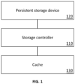
- Figure 1 shows an example storage system.
- the storage controller 110 is in communication with a persistent storage device 120.
- the persistent storage device 120 is a system for storing data in a persistent manner. Although the persistent storage device is shown as a single component, in practice it generally comprises multiple drives (such as hard disk drives or solid drive drives) arranged into groups and may be distributed over a number of storage nodes. Data is stored across the drives and may have error correcting encoding applied to reduce the risk of data loss if a component of the persistent storage device 120 fails.
- Data is stored on the persistent storage devices 120 in blocks.
- a block is a unit of data of predetermined size, such as 4 KiB (4096 bytes).
- the storage controller 110 is configured to use logical block addressing (LBA) when receiving requests to interact with the persistent storage device 120.
- LBA provides that each block of data stored on the persistent storage device 120 is identified by a unique integer LBA value.
- the storage controller 110 may translate an LBA value to determine which physical location on which drive the data is actually stored on. This translation can allow the storage controller 110 to administer the underlying storage architecture of the persistent storage device 120 freely external programs being required to record the physical location of the data.
- the storage controller 110 is further in communication with a cache 130.
- the cache comprises non-volatile memory chips configured to operate as a non-volatile cache. This may involve the use of flash memory alone or in combination with conventional volatile memory.
- the non-volatile memory chips may be configured as non-volatile dual in-line memory modules (NVDIMM).
- the storage controller is described as a single component, in practice the different functions of the storage controller may be split across different entities. For example, interactions with the cache 130 may occur through a cache controller independent of the storage controller 110.
- the storage controller is configured to administer writing data to the persistent storage device.
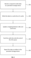
- Figure 2 shows an example approach through which the storage controller can write data.
- the storage controller receives a request to write data to a persistent storage device.
- the request comprises an indication of the data to be stored and a LBA value to indicate where the data should be stored.
- the request may be in the form of a write instruction from a program running on a processor.
- the storage controller writes the data to a cache line of the cache.
- the storage controller selects a cache line for the data.
- the cache line may be selected according to a hash of the data to be stored or a function of the virtual address.
- the storage controller ensures the cache line can store an additional page.
- the cache line may be selected according to which cache line is clean.
- the storage controller stores the data in the selected cache line.
- the cache line is then marked dirty. This occurs by updating a bit associated with the cache line. This indicates that data has been stored in the cache line but has not yet been written to the persistent storage device.
- a mapping between LBAs and cache lines is updated.
- the mapping records that, for a given cache line, the data should be stored at a given LBA value at the persistent storage device.
- a request for a read from a given LBA is received, it can be provided from the cache (instead of from the persistent storage device). This is described below with respect to Figure 5 .
- the cache line which was written to is pushed onto the end of an LRU queue.
- the LRU queue is a queue of the "least recently used" cache lines.
- the cache line at the end of queue is the cache line that was most recently written to, and the cache line at the head of the queue is the cache line that was least recently written to.
- the LRU queue can maintain this ordering without needing to explicitly retain an age of different cache lines.
- the storage controller reports the data as having been written to the persistent storage device. This occurs even though the data has not actually been written to the persistent storage device, but only remains as a page in the cache.
- This provides a benefit of highly responsive write response without the delay that may otherwise occur when writing to a persistent storage device.
- the storage controller may cause data to be moved from the cache to the persistent storage device. This process is called eviction. Eviction can occur in a number of circumstances.
- the storage controller writes the data to a cache line of the cache. This requires that the cache is not full.
- “full” means that there is at least one clean cache line in the cache. If the cache line is full, the storage controller may evict data from the cache to allow the storage controller to complete step 202.
- the storage controller may pre-emptively evict data to retain a certain level of clean capacity. That is, data may be evicted from the cache so that the cache can store a predetermined quantity of data without eviction. For example, it may be that 50% of the overall capacity of the cache should be retained as clean. This allows for improved burst performance in writing, while still allowing the improved read and modify performance for data already in the cache. Such pre-emptive eviction might only occur when the load on the storage controller is relatively low.
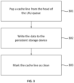
- Figure 3 shows an example approach for evicting data from the cache by writing data to the persistent storage device.
- the storage controller pops a cache line from the head of the LRU queue.
- the first item in the LRU queue indicates the cache line which was least recently used for storage of additional data.
- the head of the LRU queue becomes the second most recently used cache line in the queue.
- the data stored in the cache line is written to the persistent storage device.
- the storage controller For each page in the cache line, the storage controller causes the page to be stored according to the corresponding LBA value. This may comprise translating the LBA value to a physical address for one or more of the drives in the persistent storage device. If step 302 fails for any reason, the cache line may be re-added to the head of the LRU queue for a re-attempt at eviction.
- the selection of the one or more storage devices may be based on metadata previously stored for the data to be evicted. That is, when the data was initially stored in the cache, metadata may have been updated to map between the cache location of the data and the corresponding LBA value. In such a case, this storage device location may be used to select the one or more storage devices.
- the driver marks the corresponding cache line as clean. This allows that part of the cache to be reused.
- the driver may also update the metadata to show that the data is no longer stored in the cache, for example by removing a mapping between the cache location of the data and the corresponding LBA value.
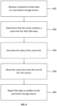
- the request When a request to write data is received at step 201, the request indicates an LBA value. In some cases, a subsequent request may be received which indicates that a different piece of data should be written to the same LBA value. In such cases, the approach of Figure 4 may be used in lieu of the approach of Figure 2 .
- the storage controller receives a request to write data to a persistent storage device. This is the same as step 201.
- the storage controller determines that the cache contains a dirty cache line with data for that LBA value.
- mapping between LBA values and cache lines includes the LBA value.
- the storage controller overwrites the previous data at that cache line to be the data of the request at step 401. This occurs even though the cache line is marked as dirty, which would the storage controller would usually avoid.
- the cache line which was written to is moved to the end of an LRU queue. That is, the cache line is removed from its previous position in the LRU queue and pushing onto the end of the queue.
- the storage controller reports the data as having been written to the persistent storage device. This occurs even though the data has not actually been written to the persistent storage device, but only remains as a page in the cache.
- the storage controller is also configured to administer reading data from the persistent storage device.
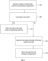
- Figure 5 shows an example approach through which the storage controller can read data.
- the storage controller receives a request to retrieve data stored on the persistent storage device.
- the request comprises an LBA value to indicate where the data should be read from.
- the request may be in the form of a read instruction from a program running on a processor, which indicates that the data should be written to a particular memory address.
- the storage controller determines if the data is in the cache.
- step 511 the storage controller checking the mapping between LBAs and cache lines. If the LBA in the request is in the mapping, then the method proceeds to step 511. If the LBA in the request is not in the mapping, then the method proceeds to step 521.
- the storage controller returns the data in the cache at the corresponding cache line.
- the storage controller may then send an indication, such as an interrupt, to the program indicating the read is complete.
- the storage controller determines the physical location of the data based on the LBA.
- the storage controller may maintain a mapping of LBA to physical location.
- the physical location may be identified as a stripe and a drive.
- the storage controller may look up the entry for the LBA in the mapping to determine the physical location.
- the storage controller returns the data from the persistent storage device. This may occur by obtaining the data from the physical location and writing the data to the memory address. The storage controller may then send an indication, such as an interrupt, to the program indicating the read is complete.
- the storage controller can selectively return data from the cache (which may be relatively fast) or from the persistent storage device (which may be relatively slow). This occurs without the program sending the request being aware of where the data is actually stored. That is, the operation of the cache is transparent to an external program.
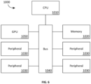
- Figure 6 shows an example system which may be used to implement the example storage controller, and therefore the methods noted above.
- the system 1000 comprises a CPU (central processing unit) 1010, a main memory 1020, one or more peripherals 1030, and a GPU (graphics processing unit) 1050.
- the CPU 1010, main memory 1020, peripherals 1030, and GPU 1050 are connected by a bus 1040.
- the bus 1040 includes a root complex, and each of the peripherals 1030 and the GPU 1050 are PCIe endpoints.
- the GPU 1050 can communicate with the peripherals 1030 directly via the bus 1040. In some cases, more than one CPU 1010 and/or more than one GPU 1050 is provided.
- the main memory 1020 may be configured to implement the cache, and so may comprise non-volatile memory chips.
- the peripherals 1030 may include a persistent storage device (such as hard disk drives, solid state drives, or the like), storage controllers (such as RAID controllers), network controllers (such as network interface cards), switches (such as PCIe switches configured to connect further peripherals), or any of a variety of devices.
- a persistent storage device such as hard disk drives, solid state drives, or the like
- storage controllers such as RAID controllers
- network controllers such as network interface cards
- switches such as PCIe switches configured to connect further peripherals
- Computer system 1000 may be used to implement the methods noted above.
- CPU 1010 and/or GPU 1050 may run a program which operates as the storage controller.
- processors may comprise a plurality of processors. That is, at least in the case of processors, the singular should be interpreted as including the plural. Where methods comprise multiple steps, different steps or different parts of a step may be performed by different processors.
Landscapes
- Engineering & Computer Science (AREA)
- Theoretical Computer Science (AREA)
- Physics & Mathematics (AREA)
- General Engineering & Computer Science (AREA)
- General Physics & Mathematics (AREA)
- Memory System Of A Hierarchy Structure (AREA)
Description
- This relates to cache operation for a persistent storage device.
- Data is stored on a persistent storage device, such as a number of drives. When data is to be written, a storage controller receives the write request and causes the data to be written onto the persistent storage device. When data is to be read, the storage controller receives the read request and returns the data.
-
US8402226B1 , titled "Rate proportional cache write-back in a storage server", discloses a method of cache writeback in a data storage system. There is disclosed a storage server that is configured to respond to an asynchronous or fast write request from a client by writing new data to a page of data in the cache memory, and then immediately returning an acknowledgement of the write request to the client, before the new data is written back to the storage array. There is also disclosed a way of ensuring persistence time of a dirty page in the cache by placing each dirty page onto the tail of a dirty LRU list kept in the cache memory. -
US2012110247A1 , titled "MANAGEMENT OF CACHE MEMORY IN A FLASH CACHE ARCHITECTURE", discloses a method for managing cache memory in a flash cache architecture. The method includes providing a storage cache controller, at least a flash memory comprising a flash controller, and at least a backend storage device, and maintaining read cache metadata for tracking on the flash memory cached data to be read, and write cache metadata for tracking on the flash memory data expected to be cached. -
US5586291A , titled "Disk controller with volatile and non-volatile cache memories", discloses a disk storage subsystem includes both volatile and non-volatile portions of memory. In response to a write command from a host computer, the controller allocates a predetermined number of memory blocks in the non-volatile cache memory and allocates a corresponding number of blocks in the volatile memory. Host supplied write data is then stored in the allocated non-volatile memory blocks. Immediately thereafter the subsystem sends an acknowledge signal to the host. Subsequent reads of the given data may be read from the volatile memory, reducing disk access time. In the event of a power failure, data stored in the non-volatile memory but not yet written to disk is preserved. -
EP3117331A1 , titled "DYNAMICALLY MODIFYING DURABILITY PROPERTIES FOR INDIVIDUAL DATA VOLUMES", discloses a block-based storage system which may implement dynamic durability adjustment for page cache write logging. - The invention is defined in the appended claims.
- The dependent claims set out particular embodiments.
- In a first example embodiment, there is provided a method comprising:
receiving a request to write data to a persistent storage device, the request comprising an LBA value; writing the data to a cache line of a cache; updating a mapping between LBA values and cache lines; receiving a subsequent request to write data to the persistent storage device, the subsequent request comprising the LBA value; determining that the LBA value exists in the mapping; determining a cache line corresponding to the LBA value; updating the corresponding cache line to the data of the subsequent request; pushing the cache line onto the end of a least recently used (LRU) queue of cache lines; and reporting the data as having been written to the persistent storage device. - Preferably, pushing the cache line onto the end of a least recently used (LRU) queue of cache lines comprises: removing the cache line corresponding to the LBA value from the LRU queue; and pushing the cache line corresponding to the LBA value onto the end of the LRU queue.
- Preferably, the method further comprises: receiving a request to read data from the persistent storage device; determining that the data is in the cache; and providing the data from the cache.
- Preferably, the request to read data comprises an LBA value, and determining that the data is in the cache comprises: determining that the LBA value is in the mapping between LBA values and cache lines.
- Preferably, providing the data from the cache comprises: providing the data from the cache line corresponding to the LBA value in the mapping between LBA values and cache lines.
- Preferably, the method further comprises: determining that data is to be evicted from the cache; and evicting data from the cache.
- Preferably, evicting data from the cache comprises: popping a first cache line from the head of the LRU queue; and writing the data at the first cache line to the persistent storage device.
- Preferably, the method further comprises: marking the first cache line as clean.
- Preferably, determining that data is to be evicted from the cache comprises: determining that the cache is below a threshold clean capacity.
- Preferably, the method further comprises: after writing the data to a cache line of a cache, marking the cache line as dirty.
- In a second example embodiment, there is provided a system comprising: one or more processors; and a memory; wherein the memory comprises instructions which, when executed by the one or more processors, configure the one or more processors to perform the method of the first example embodiment.
- In a third example embodiment, there is provided a computer program product comprising instructions which, when executed by one or more processors, cause the one or more processors to perform the method of the first example embodiment.
- The description is framed by way of example with reference to the drawings which show certain embodiments. However, these drawings are provided for illustration only, and do not exhaustively set out all embodiments.
-
Figure 1 shows an example storage system. -
Figure 2 shows an example approach for writing data. -
Figure 3 shows an example approach for evicting data from a cache. -
Figure 4 shows an example approach for overwriting data in the cache. -
Figure 5 shows an example approach for reading data. -
Figure 6 shows an example system for implementing a storage controller. - An approach for a storage controller is described which allows the storage controller to handle requests to write data on a persistent storage device. The persistent storage device is a system for storing data in a persistent manner and may comprise a number of drives in different configurations. Before data is stored on the persistent storage device, the storage controller stores the data in a cache. This can allow for writes to be reported as completed once the data is in the cache, even before it is written to the persistent storage device.
- The cache has multiple cache lines. Each cache line is a division of the cache which is read and written to in a single unit. Each cache line may have capacity for a predetermined number of pages. A page is a unit of data set by a processor architecture, which may be 4 KiB (that is, 1024 bytes). A cache line might be configured to store 63 pages.
-
Figure 1 shows an example storage system. - The
storage controller 110 is in communication with apersistent storage device 120. Thepersistent storage device 120 is a system for storing data in a persistent manner. Although the persistent storage device is shown as a single component, in practice it generally comprises multiple drives (such as hard disk drives or solid drive drives) arranged into groups and may be distributed over a number of storage nodes. Data is stored across the drives and may have error correcting encoding applied to reduce the risk of data loss if a component of thepersistent storage device 120 fails. - Data is stored on the
persistent storage devices 120 in blocks. A block is a unit of data of predetermined size, such as 4 KiB (4096 bytes). Thestorage controller 110 is configured to use logical block addressing (LBA) when receiving requests to interact with thepersistent storage device 120. LBA provides that each block of data stored on thepersistent storage device 120 is identified by a unique integer LBA value. Thestorage controller 110 may translate an LBA value to determine which physical location on which drive the data is actually stored on. This translation can allow thestorage controller 110 to administer the underlying storage architecture of thepersistent storage device 120 freely external programs being required to record the physical location of the data. - The
storage controller 110 is further in communication with acache 130. The cache comprises non-volatile memory chips configured to operate as a non-volatile cache. This may involve the use of flash memory alone or in combination with conventional volatile memory. The non-volatile memory chips may be configured as non-volatile dual in-line memory modules (NVDIMM). - While the storage controller is described as a single component, in practice the different functions of the storage controller may be split across different entities. For example, interactions with the
cache 130 may occur through a cache controller independent of thestorage controller 110. - The storage controller is configured to administer writing data to the persistent storage device.
Figure 2 shows an example approach through which the storage controller can write data. - At
step 201, the storage controller receives a request to write data to a persistent storage device. - The request comprises an indication of the data to be stored and a LBA value to indicate where the data should be stored. The request may be in the form of a write instruction from a program running on a processor.
- At
step 202, the storage controller writes the data to a cache line of the cache. - To achieve this, the storage controller selects a cache line for the data. The cache line may be selected according to a hash of the data to be stored or a function of the virtual address. The storage controller ensures the cache line can store an additional page. Alternatively, the cache line may be selected according to which cache line is clean.
- The storage controller stores the data in the selected cache line. The cache line is then marked dirty. This occurs by updating a bit associated with the cache line. This indicates that data has been stored in the cache line but has not yet been written to the persistent storage device.
- Where all cache lines are full, data may need to be evicted from the cache before the data is stored in the cache. Eviction is described below with respect to
Figure 3 . - At
step 203, a mapping between LBAs and cache lines is updated. The mapping records that, for a given cache line, the data should be stored at a given LBA value at the persistent storage device. In addition, if a request for a read from a given LBA is received, it can be provided from the cache (instead of from the persistent storage device). This is described below with respect toFigure 5 . - At
step 204, the cache line which was written to is pushed onto the end of an LRU queue. The LRU queue is a queue of the "least recently used" cache lines. The cache line at the end of queue is the cache line that was most recently written to, and the cache line at the head of the queue is the cache line that was least recently written to. The LRU queue can maintain this ordering without needing to explicitly retain an age of different cache lines. - At
step 205, after the storage controller writes the data to the cache, the storage controller reports the data as having been written to the persistent storage device. This occurs even though the data has not actually been written to the persistent storage device, but only remains as a page in the cache. - This provides a benefit of highly responsive write response without the delay that may otherwise occur when writing to a persistent storage device.
- The storage controller may cause data to be moved from the cache to the persistent storage device. This process is called eviction. Eviction can occur in a number of circumstances.
- For example, at
step 202, the storage controller writes the data to a cache line of the cache. This requires that the cache is not full. In this context, "full" means that there is at least one clean cache line in the cache. If the cache line is full, the storage controller may evict data from the cache to allow the storage controller to completestep 202. - Alternatively, the storage controller may pre-emptively evict data to retain a certain level of clean capacity. That is, data may be evicted from the cache so that the cache can store a predetermined quantity of data without eviction. For example, it may be that 50% of the overall capacity of the cache should be retained as clean. This allows for improved burst performance in writing, while still allowing the improved read and modify performance for data already in the cache. Such pre-emptive eviction might only occur when the load on the storage controller is relatively low.
-
Figure 3 shows an example approach for evicting data from the cache by writing data to the persistent storage device. - At
step 301, the storage controller pops a cache line from the head of the LRU queue. The first item in the LRU queue indicates the cache line which was least recently used for storage of additional data. As a result, the head of the LRU queue becomes the second most recently used cache line in the queue. - At
step 302, the data stored in the cache line is written to the persistent storage device. For each page in the cache line, the storage controller causes the page to be stored according to the corresponding LBA value. This may comprise translating the LBA value to a physical address for one or more of the drives in the persistent storage device. Ifstep 302 fails for any reason, the cache line may be re-added to the head of the LRU queue for a re-attempt at eviction. - The selection of the one or more storage devices may be based on metadata previously stored for the data to be evicted. That is, when the data was initially stored in the cache, metadata may have been updated to map between the cache location of the data and the corresponding LBA value. In such a case, this storage device location may be used to select the one or more storage devices.
- At
step 303, after the data has been written to the one or more storage devices, the driver marks the corresponding cache line as clean. This allows that part of the cache to be reused. The driver may also update the metadata to show that the data is no longer stored in the cache, for example by removing a mapping between the cache location of the data and the corresponding LBA value. - In this way, data is evicted from the cache to free space in the cache when necessary.
- When a request to write data is received at
step 201, the request indicates an LBA value. In some cases, a subsequent request may be received which indicates that a different piece of data should be written to the same LBA value. In such cases, the approach ofFigure 4 may be used in lieu of the approach ofFigure 2 . - At
step 401, the storage controller receives a request to write data to a persistent storage device. This is the same asstep 201. - At
step 402, the storage controller determines that the cache contains a dirty cache line with data for that LBA value. - This occurs by identifying that the mapping between LBA values and cache lines includes the LBA value.
- At
step 403, the storage controller overwrites the previous data at that cache line to be the data of the request atstep 401. This occurs even though the cache line is marked as dirty, which would the storage controller would usually avoid. - At
step 404, the cache line which was written to is moved to the end of an LRU queue. That is, the cache line is removed from its previous position in the LRU queue and pushing onto the end of the queue. - At
step 405, after the storage controller writes the data to the cache, the storage controller reports the data as having been written to the persistent storage device. This occurs even though the data has not actually been written to the persistent storage device, but only remains as a page in the cache. - This can avoid a needless write to the persistent storage device: since the subsequent write request would have overwritten the data on the persistent storage device anyway, overwriting the data in the cache does not cause any unexpected data loss. This can reduce the total number of writes to the persistent storage device, and therefore can improve the aggregate performance of the storage system.
- In addition, if a particular LBA value is written to, there is a likelihood it will be written to again. By resetting the location of the corresponding cache line in the LRU queue, this can cause a "hot" LBA to stay in cache rather than being written to persistent storage repeatedly. This can further reduce the total number of writes to the persistent storage device, and therefore can further improve the aggregate performance of the storage system.
- The storage controller is also configured to administer reading data from the persistent storage device.
Figure 5 shows an example approach through which the storage controller can read data. - At
step 501, the storage controller receives a request to retrieve data stored on the persistent storage device. - The request comprises an LBA value to indicate where the data should be read from. The request may be in the form of a read instruction from a program running on a processor, which indicates that the data should be written to a particular memory address.
- At
step 502, the storage controller determines if the data is in the cache. - This occurs by the storage controller checking the mapping between LBAs and cache lines. If the LBA in the request is in the mapping, then the method proceeds to step 511. If the LBA in the request is not in the mapping, then the method proceeds to step 521.
- At
step 511, the storage controller returns the data in the cache at the corresponding cache line. - This may occur by copying the data from the cache line to the memory address. The storage controller may then send an indication, such as an interrupt, to the program indicating the read is complete.
- At
step 521, the storage controller determines the physical location of the data based on the LBA. - For example, the storage controller may maintain a mapping of LBA to physical location. The physical location may be identified as a stripe and a drive. In this case, the storage controller may look up the entry for the LBA in the mapping to determine the physical location.
- At
step 522, the storage controller returns the data from the persistent storage device. This may occur by obtaining the data from the physical location and writing the data to the memory address. The storage controller may then send an indication, such as an interrupt, to the program indicating the read is complete. - In this way, the storage controller can selectively return data from the cache (which may be relatively fast) or from the persistent storage device (which may be relatively slow). This occurs without the program sending the request being aware of where the data is actually stored. That is, the operation of the cache is transparent to an external program.
-
Figure 6 shows an example system which may be used to implement the example storage controller, and therefore the methods noted above. - The
system 1000 comprises a CPU (central processing unit) 1010, amain memory 1020, one ormore peripherals 1030, and a GPU (graphics processing unit) 1050. TheCPU 1010,main memory 1020,peripherals 1030, andGPU 1050 are connected by abus 1040. In the case of a PCIe (PCI Express) topology, thebus 1040 includes a root complex, and each of theperipherals 1030 and theGPU 1050 are PCIe endpoints. TheGPU 1050 can communicate with theperipherals 1030 directly via thebus 1040. In some cases, more than oneCPU 1010 and/or more than oneGPU 1050 is provided. - The
main memory 1020 may be configured to implement the cache, and so may comprise non-volatile memory chips. - The
peripherals 1030 may include a persistent storage device (such as hard disk drives, solid state drives, or the like), storage controllers (such as RAID controllers), network controllers (such as network interface cards), switches (such as PCIe switches configured to connect further peripherals), or any of a variety of devices. -
Computer system 1000 may be used to implement the methods noted above. For example,CPU 1010 and/orGPU 1050 may run a program which operates as the storage controller. - A number of methods have been described above. Any of these methods may be embodied in a series of instructions, which may form a computer program. These instructions, or this computer program, may be stored on a computer readable medium, which may be non-transitory. When executed, these instructions or this program cause a processor to perform the described methods.
- Where an approach has been described as being implemented by a processor, this may comprise a plurality of processors. That is, at least in the case of processors, the singular should be interpreted as including the plural. Where methods comprise multiple steps, different steps or different parts of a step may be performed by different processors.
- The steps of the methods have been described in a particular order for ease of understanding. However, the steps can be performed in a different order from that specified, or with steps being performed in parallel. This is the case in all methods except where one step is dependent on another having been performed.
- The term "comprises" and other grammatical forms is intended to have an inclusive meaning unless otherwise noted. That is, they should be taken to mean an inclusion of the listed components, and possibly of other non-specified components or elements.
Claims (12)
- A method comprising:receiving a request to write data to a persistent storage device, the request comprising an LBA value (201);writing the data to a cache line of a cache (202);updating a mapping between LBA values and cache lines (203);receiving a subsequent request to write data to the persistent storage device, the subsequent request comprising the LBA value (401);determining that the LBA value exists in the mapping (402);determining a cache line corresponding to the LBA value (402);updating the corresponding cache line to the data of the subsequent request (403);pushing the cache line onto the end of a least recently used (LRU) queue of cache lines (204); andreporting the data as having been written to the persistent storage device (205).
- The method of claim 1, wherein pushing the cache line onto the end of a least recently used (LRU) queue of cache lines comprises:removing the cache line corresponding to the LBA value from the LRU queue; andpushing the cache line corresponding to the LBA value onto the end of the LRU queue.
- The method of claim 1 or claim 2, further comprising:receiving a request to read data from the persistent storage device;determining that the data is in the cache; andproviding the data from the cache.
- The method of claim 3, the request to read data comprises an LBA value, and determining that the data is in the cache comprises:
determining that the LBA value is in the mapping between LBA values and cache lines. - The method of claim 4, wherein providing the data from the cache comprises:
providing the data from the cache line corresponding to the LBA value in the mapping between LBA values and cache lines. - The method of any one of claims 1 to 5, further comprising:determining that data is to be evicted from the cache; andevicting data from the cache.
- The method of claim 6, wherein evicting data from the cache comprises:popping a first cache line from the head of the LRU queue; andwriting the data at the first cache line to the persistent storage device.
- The method of claim 7, further comprising:
marking the first cache line as clean. - The method of any one of claims 6 to 8, wherein determining that data is to be evicted from the cache comprises:
determining that the cache is below a threshold clean capacity. - The method of any one of claims 1 to 9, further comprising:
after writing the data to a cache line of a cache, marking the cache line as dirty. - A system comprising:one or more processors; anda memory;wherein the memory comprises instructions which, when executed by the one or more processors, cause the one or more processors to performthe method of any one of claims 1 to 10.
- A non-transitory computer readable medium comprising instructions which, when executed by one or more processors, cause the one or more processors to perform the method of any one of claims 1 to 10.
Applications Claiming Priority (1)
| Application Number | Priority Date | Filing Date | Title |
|---|---|---|---|
| US202163149841P | 2021-02-16 | 2021-02-16 |
Publications (3)
| Publication Number | Publication Date |
|---|---|
| EP4044038A1 EP4044038A1 (en) | 2022-08-17 |
| EP4044038B1 true EP4044038B1 (en) | 2024-11-27 |
| EP4044038C0 EP4044038C0 (en) | 2024-11-27 |
Family
ID=80683020
Family Applications (1)
| Application Number | Title | Priority Date | Filing Date |
|---|---|---|---|
| EP22156693.8A Active EP4044038B1 (en) | 2021-02-16 | 2022-02-15 | Cache operation for a persistent storage device |
Country Status (2)
| Country | Link |
|---|---|
| US (1) | US12468636B2 (en) |
| EP (1) | EP4044038B1 (en) |
Families Citing this family (1)
| Publication number | Priority date | Publication date | Assignee | Title |
|---|---|---|---|---|
| EP4698990A1 (en) * | 2023-04-19 | 2026-02-25 | Daedalus Cloud LLC | Methods for continuously writing resilient data |
Family Cites Families (16)
| Publication number | Priority date | Publication date | Assignee | Title |
|---|---|---|---|---|
| US5586291A (en) | 1994-12-23 | 1996-12-17 | Emc Corporation | Disk controller with volatile and non-volatile cache memories |
| US6658533B1 (en) | 2000-09-21 | 2003-12-02 | Intel Corporation | Method and apparatus for write cache flush and fill mechanisms |
| US6654855B1 (en) | 2000-10-26 | 2003-11-25 | Emc Corporation | Method and apparatus for improving the efficiency of cache memories using chained metrics |
| US7027064B2 (en) | 2002-02-28 | 2006-04-11 | Sun Microsystems, Inc. | Active block write-back from SRAM cache to DRAM |
| US6701393B1 (en) * | 2002-06-27 | 2004-03-02 | Emc Corporation | Systems and methods for managing storage location descriptors |
| US6889288B2 (en) * | 2002-12-02 | 2005-05-03 | Emc Corporation | Reducing data copy operations for writing data from a network to storage of a cached data storage system by organizing cache blocks as linked lists of data fragments |
| US7536529B1 (en) * | 2005-06-10 | 2009-05-19 | American Megatrends, Inc. | Method, system, apparatus, and computer-readable medium for provisioning space in a data storage system |
| WO2007068122A1 (en) | 2005-12-16 | 2007-06-21 | Univ Western Ontario | System and method for cache management |
| US8402226B1 (en) * | 2010-06-18 | 2013-03-19 | Emc Corporation | Rate proportional cache write-back in a storage server |
| US9135181B2 (en) | 2010-10-27 | 2015-09-15 | International Business Machines Corporation | Management of cache memory in a flash cache architecture |
| US9342457B2 (en) | 2014-03-11 | 2016-05-17 | Amazon Technologies, Inc. | Dynamically modifying durability properties for individual data volumes |
| US20170091099A1 (en) * | 2015-09-25 | 2017-03-30 | Zvika Greenfield | Memory controller for multi-level system memory having sectored cache |
| US9710383B1 (en) * | 2015-09-29 | 2017-07-18 | EMC IP Holding Company LLC | Caching techniques |
| US9952973B2 (en) | 2015-10-29 | 2018-04-24 | Western Digital Technologies, Inc. | Reducing write-backs to memory by controlling the age of cache lines in lower level cache |
| CN111930558B (en) * | 2019-05-13 | 2023-03-03 | 华为技术有限公司 | Database system failure recovery method, database system and computing device |
| US11210231B2 (en) * | 2019-10-28 | 2021-12-28 | EMC IP Holding Company LLC | Cache management using a bucket-partitioned hash table |
-
2022
- 2022-02-10 US US17/669,131 patent/US12468636B2/en active Active
- 2022-02-15 EP EP22156693.8A patent/EP4044038B1/en active Active
Also Published As
| Publication number | Publication date |
|---|---|
| US20220261356A1 (en) | 2022-08-18 |
| EP4044038C0 (en) | 2024-11-27 |
| US12468636B2 (en) | 2025-11-11 |
| EP4044038A1 (en) | 2022-08-17 |
Similar Documents
| Publication | Publication Date | Title |
|---|---|---|
| US8645626B2 (en) | Hard disk drive with attached solid state drive cache | |
| US6467022B1 (en) | Extending adapter memory with solid state disks in JBOD and RAID environments | |
| US9280478B2 (en) | Cache rebuilds based on tracking data for cache entries | |
| JP7010809B2 (en) | Deducible memory cache and how it works | |
| US20150149742A1 (en) | Memory unit and method | |
| WO2011076565A1 (en) | Hybrid storage subsystem | |
| EP3182291B1 (en) | System and method for exclusive read caching in a virtualized computing environment | |
| US10152422B1 (en) | Page-based method for optimizing cache metadata updates | |
| US9940023B2 (en) | System and method for an accelerator cache and physical storage tier | |
| US11436150B2 (en) | Method for processing page fault by processor | |
| US11782842B1 (en) | Techniques for reclaiming dirty cache pages | |
| US20260023689A1 (en) | Systems, methods, and apparatus for accessing data in versions of memory pages | |
| US12197341B2 (en) | Affinity-based cache operation for a persistent storage device | |
| CN120780615A (en) | Nonvolatile memory controller with partial logical to physical address translation table | |
| US20240211406A1 (en) | Systems, methods, and apparatus for accessing data from memory or storage at a storage node | |
| US12468636B2 (en) | Cache operation for a persistent storage device | |
| US9454488B2 (en) | Systems and methods to manage cache data storage | |
| US20250156330A1 (en) | System and method for application agnostic device cache for tiered memory device | |
| US9864688B1 (en) | Discarding cached data before cache flush | |
| US12541326B2 (en) | Device cache engine for a cache-coherent interconnect memory expansion | |
| US20140351521A1 (en) | Storage system and method for controlling storage system | |
| EP4432093A1 (en) | Systems and methods for monitoring memory accesses | |
| US11436151B2 (en) | Semi-sequential drive I/O performance | |
| US9304918B2 (en) | Computer system and cache control method | |
| CN116909947A (en) | Method for address translation and persistent storage device |
Legal Events
| Date | Code | Title | Description |
|---|---|---|---|
| PUAI | Public reference made under article 153(3) epc to a published international application that has entered the european phase |
Free format text: ORIGINAL CODE: 0009012 |
|
| STAA | Information on the status of an ep patent application or granted ep patent |
Free format text: STATUS: THE APPLICATION HAS BEEN PUBLISHED |
|
| AK | Designated contracting states |
Kind code of ref document: A1 Designated state(s): AL AT BE BG CH CY CZ DE DK EE ES FI FR GB GR HR HU IE IS IT LI LT LU LV MC MK MT NL NO PL PT RO RS SE SI SK SM TR |
|
| STAA | Information on the status of an ep patent application or granted ep patent |
Free format text: STATUS: REQUEST FOR EXAMINATION WAS MADE |
|
| 17P | Request for examination filed |
Effective date: 20230217 |
|
| RBV | Designated contracting states (corrected) |
Designated state(s): AL AT BE BG CH CY CZ DE DK EE ES FI FR GB GR HR HU IE IS IT LI LT LU LV MC MK MT NL NO PL PT RO RS SE SI SK SM TR |
|
| GRAP | Despatch of communication of intention to grant a patent |
Free format text: ORIGINAL CODE: EPIDOSNIGR1 |
|
| STAA | Information on the status of an ep patent application or granted ep patent |
Free format text: STATUS: GRANT OF PATENT IS INTENDED |
|
| INTG | Intention to grant announced |
Effective date: 20240621 |
|
| RAP3 | Party data changed (applicant data changed or rights of an application transferred) |
Owner name: DAEDALUS CLOUD LLC |
|
| GRAS | Grant fee paid |
Free format text: ORIGINAL CODE: EPIDOSNIGR3 |
|
| GRAA | (expected) grant |
Free format text: ORIGINAL CODE: 0009210 |
|
| STAA | Information on the status of an ep patent application or granted ep patent |
Free format text: STATUS: THE PATENT HAS BEEN GRANTED |
|
| AK | Designated contracting states |
Kind code of ref document: B1 Designated state(s): AL AT BE BG CH CY CZ DE DK EE ES FI FR GB GR HR HU IE IS IT LI LT LU LV MC MK MT NL NO PL PT RO RS SE SI SK SM TR |
|
| REG | Reference to a national code |
Ref country code: GB Ref legal event code: FG4D |
|
| REG | Reference to a national code |
Ref country code: CH Ref legal event code: EP |
|
| REG | Reference to a national code |
Ref country code: DE Ref legal event code: R096 Ref document number: 602022008037 Country of ref document: DE |
|
| REG | Reference to a national code |
Ref country code: IE Ref legal event code: FG4D |
|
| U01 | Request for unitary effect filed |
Effective date: 20241127 |
|
| U07 | Unitary effect registered |
Designated state(s): AT BE BG DE DK EE FI FR IT LT LU LV MT NL PT RO SE SI Effective date: 20241203 |
|
| U20 | Renewal fee for the european patent with unitary effect paid |
Year of fee payment: 4 Effective date: 20250224 |
|
| PG25 | Lapsed in a contracting state [announced via postgrant information from national office to epo] |
Ref country code: IS Free format text: LAPSE BECAUSE OF FAILURE TO SUBMIT A TRANSLATION OF THE DESCRIPTION OR TO PAY THE FEE WITHIN THE PRESCRIBED TIME-LIMIT Effective date: 20250327 Ref country code: HR Free format text: LAPSE BECAUSE OF FAILURE TO SUBMIT A TRANSLATION OF THE DESCRIPTION OR TO PAY THE FEE WITHIN THE PRESCRIBED TIME-LIMIT Effective date: 20241127 |
|
| PG25 | Lapsed in a contracting state [announced via postgrant information from national office to epo] |
Ref country code: ES Free format text: LAPSE BECAUSE OF FAILURE TO SUBMIT A TRANSLATION OF THE DESCRIPTION OR TO PAY THE FEE WITHIN THE PRESCRIBED TIME-LIMIT Effective date: 20241127 |
|
| PG25 | Lapsed in a contracting state [announced via postgrant information from national office to epo] |
Ref country code: NO Free format text: LAPSE BECAUSE OF FAILURE TO SUBMIT A TRANSLATION OF THE DESCRIPTION OR TO PAY THE FEE WITHIN THE PRESCRIBED TIME-LIMIT Effective date: 20250227 |
|
| PG25 | Lapsed in a contracting state [announced via postgrant information from national office to epo] |
Ref country code: GR Free format text: LAPSE BECAUSE OF FAILURE TO SUBMIT A TRANSLATION OF THE DESCRIPTION OR TO PAY THE FEE WITHIN THE PRESCRIBED TIME-LIMIT Effective date: 20250228 |
|
| PG25 | Lapsed in a contracting state [announced via postgrant information from national office to epo] |
Ref country code: PL Free format text: LAPSE BECAUSE OF FAILURE TO SUBMIT A TRANSLATION OF THE DESCRIPTION OR TO PAY THE FEE WITHIN THE PRESCRIBED TIME-LIMIT Effective date: 20241127 |
|
| PG25 | Lapsed in a contracting state [announced via postgrant information from national office to epo] |
Ref country code: RS Free format text: LAPSE BECAUSE OF FAILURE TO SUBMIT A TRANSLATION OF THE DESCRIPTION OR TO PAY THE FEE WITHIN THE PRESCRIBED TIME-LIMIT Effective date: 20250227 |
|
| PG25 | Lapsed in a contracting state [announced via postgrant information from national office to epo] |
Ref country code: SM Free format text: LAPSE BECAUSE OF FAILURE TO SUBMIT A TRANSLATION OF THE DESCRIPTION OR TO PAY THE FEE WITHIN THE PRESCRIBED TIME-LIMIT Effective date: 20241127 |
|
| PG25 | Lapsed in a contracting state [announced via postgrant information from national office to epo] |
Ref country code: SK Free format text: LAPSE BECAUSE OF FAILURE TO SUBMIT A TRANSLATION OF THE DESCRIPTION OR TO PAY THE FEE WITHIN THE PRESCRIBED TIME-LIMIT Effective date: 20241127 |
|
| PG25 | Lapsed in a contracting state [announced via postgrant information from national office to epo] |
Ref country code: CZ Free format text: LAPSE BECAUSE OF FAILURE TO SUBMIT A TRANSLATION OF THE DESCRIPTION OR TO PAY THE FEE WITHIN THE PRESCRIBED TIME-LIMIT Effective date: 20241127 |
|
| PG25 | Lapsed in a contracting state [announced via postgrant information from national office to epo] |
Ref country code: MC Free format text: LAPSE BECAUSE OF FAILURE TO SUBMIT A TRANSLATION OF THE DESCRIPTION OR TO PAY THE FEE WITHIN THE PRESCRIBED TIME-LIMIT Effective date: 20241127 |
|
| REG | Reference to a national code |
Ref country code: CH Ref legal event code: PL |
|
| PLBE | No opposition filed within time limit |
Free format text: ORIGINAL CODE: 0009261 |
|
| STAA | Information on the status of an ep patent application or granted ep patent |
Free format text: STATUS: NO OPPOSITION FILED WITHIN TIME LIMIT |
|
| PG25 | Lapsed in a contracting state [announced via postgrant information from national office to epo] |
Ref country code: CH Free format text: LAPSE BECAUSE OF NON-PAYMENT OF DUE FEES Effective date: 20250228 |
|
| 26N | No opposition filed |
Effective date: 20250828 |
|
| PG25 | Lapsed in a contracting state [announced via postgrant information from national office to epo] |
Ref country code: IE Free format text: LAPSE BECAUSE OF NON-PAYMENT OF DUE FEES Effective date: 20250215 |
|
| U20 | Renewal fee for the european patent with unitary effect paid |
Year of fee payment: 5 Effective date: 20260224 |
|
| PG25 | Lapsed in a contracting state [announced via postgrant information from national office to epo] |
Ref country code: CY Free format text: LAPSE BECAUSE OF FAILURE TO SUBMIT A TRANSLATION OF THE DESCRIPTION OR TO PAY THE FEE WITHIN THE PRESCRIBED TIME-LIMIT Effective date: 20241127 |
|
| PG25 | Lapsed in a contracting state [announced via postgrant information from national office to epo] |
Ref country code: TR Free format text: LAPSE BECAUSE OF FAILURE TO SUBMIT A TRANSLATION OF THE DESCRIPTION OR TO PAY THE FEE WITHIN THE PRESCRIBED TIME-LIMIT Effective date: 20241127 |