EP4043998A1 - Apparatus, system, and method for protecting power connectors against high-power arcing - Google Patents
Apparatus, system, and method for protecting power connectors against high-power arcing Download PDFInfo
- Publication number
- EP4043998A1 EP4043998A1 EP21171261.7A EP21171261A EP4043998A1 EP 4043998 A1 EP4043998 A1 EP 4043998A1 EP 21171261 A EP21171261 A EP 21171261A EP 4043998 A1 EP4043998 A1 EP 4043998A1
- Authority
- EP
- European Patent Office
- Prior art keywords
- power
- enclosure
- connector
- supply module
- power connector
- Prior art date
- Legal status (The legal status is an assumption and is not a legal conclusion. Google has not performed a legal analysis and makes no representation as to the accuracy of the status listed.)
- Granted
Links
Images










Classifications
-
- G—PHYSICS
- G06—COMPUTING OR CALCULATING; COUNTING
- G06F—ELECTRIC DIGITAL DATA PROCESSING
- G06F1/00—Details not covered by groups G06F3/00 - G06F13/00 and G06F21/00
- G06F1/26—Power supply means, e.g. regulation thereof
- G06F1/28—Supervision thereof, e.g. detecting power-supply failure by out of limits supervision
-
- H—ELECTRICITY
- H01—ELECTRIC ELEMENTS
- H01R—ELECTRICALLY-CONDUCTIVE CONNECTIONS; STRUCTURAL ASSOCIATIONS OF A PLURALITY OF MUTUALLY-INSULATED ELECTRICAL CONNECTING ELEMENTS; COUPLING DEVICES; CURRENT COLLECTORS
- H01R13/00—Details of coupling devices of the kinds covered by groups H01R12/70 or H01R24/00 - H01R33/00
- H01R13/66—Structural association with built-in electrical component
- H01R13/70—Structural association with built-in electrical component with built-in switch
- H01R13/703—Structural association with built-in electrical component with built-in switch operated by engagement or disengagement of coupling parts, e.g. dual-continuity coupling part
- H01R13/7036—Structural association with built-in electrical component with built-in switch operated by engagement or disengagement of coupling parts, e.g. dual-continuity coupling part the switch being in series with coupling part, e.g. dead coupling, explosion proof coupling
- H01R13/7038—Structural association with built-in electrical component with built-in switch operated by engagement or disengagement of coupling parts, e.g. dual-continuity coupling part the switch being in series with coupling part, e.g. dead coupling, explosion proof coupling making use of a remote controlled switch, e.g. relais, solid state switch activated by the engagement of the coupling parts
-
- H—ELECTRICITY
- H01—ELECTRIC ELEMENTS
- H01H—ELECTRIC SWITCHES; RELAYS; SELECTORS; EMERGENCY PROTECTIVE DEVICES
- H01H9/00—Details of switching devices, not covered by groups H01H1/00 - H01H7/00
- H01H9/30—Means for extinguishing or preventing arc between current-carrying parts
-
- G—PHYSICS
- G06—COMPUTING OR CALCULATING; COUNTING
- G06F—ELECTRIC DIGITAL DATA PROCESSING
- G06F1/00—Details not covered by groups G06F3/00 - G06F13/00 and G06F21/00
- G06F1/16—Constructional details or arrangements
- G06F1/18—Packaging or power distribution
- G06F1/181—Enclosures
- G06F1/182—Enclosures with special features, e.g. for use in industrial environments; grounding or shielding against radio frequency interference [RFI] or electromagnetical interference [EMI]
-
- G—PHYSICS
- G06—COMPUTING OR CALCULATING; COUNTING
- G06F—ELECTRIC DIGITAL DATA PROCESSING
- G06F1/00—Details not covered by groups G06F3/00 - G06F13/00 and G06F21/00
- G06F1/26—Power supply means, e.g. regulation thereof
-
- H—ELECTRICITY
- H01—ELECTRIC ELEMENTS
- H01R—ELECTRICALLY-CONDUCTIVE CONNECTIONS; STRUCTURAL ASSOCIATIONS OF A PLURALITY OF MUTUALLY-INSULATED ELECTRICAL CONNECTING ELEMENTS; COUPLING DEVICES; CURRENT COLLECTORS
- H01R13/00—Details of coupling devices of the kinds covered by groups H01R12/70 or H01R24/00 - H01R33/00
- H01R13/62—Means for facilitating engagement or disengagement of coupling parts or for holding them in engagement
- H01R13/621—Bolt, set screw or screw clamp
- H01R13/6215—Bolt, set screw or screw clamp using one or more bolts
-
- H—ELECTRICITY
- H01—ELECTRIC ELEMENTS
- H01R—ELECTRICALLY-CONDUCTIVE CONNECTIONS; STRUCTURAL ASSOCIATIONS OF A PLURALITY OF MUTUALLY-INSULATED ELECTRICAL CONNECTING ELEMENTS; COUPLING DEVICES; CURRENT COLLECTORS
- H01R13/00—Details of coupling devices of the kinds covered by groups H01R12/70 or H01R24/00 - H01R33/00
- H01R13/62—Means for facilitating engagement or disengagement of coupling parts or for holding them in engagement
- H01R13/639—Additional means for holding or locking coupling parts together, after engagement, e.g. separate keylock, retainer strap
-
- H—ELECTRICITY
- H01—ELECTRIC ELEMENTS
- H01R—ELECTRICALLY-CONDUCTIVE CONNECTIONS; STRUCTURAL ASSOCIATIONS OF A PLURALITY OF MUTUALLY-INSULATED ELECTRICAL CONNECTING ELEMENTS; COUPLING DEVICES; CURRENT COLLECTORS
- H01R13/00—Details of coupling devices of the kinds covered by groups H01R12/70 or H01R24/00 - H01R33/00
- H01R13/66—Structural association with built-in electrical component
- H01R13/70—Structural association with built-in electrical component with built-in switch
- H01R13/703—Structural association with built-in electrical component with built-in switch operated by engagement or disengagement of coupling parts, e.g. dual-continuity coupling part
-
- H—ELECTRICITY
- H01—ELECTRIC ELEMENTS
- H01R—ELECTRICALLY-CONDUCTIVE CONNECTIONS; STRUCTURAL ASSOCIATIONS OF A PLURALITY OF MUTUALLY-INSULATED ELECTRICAL CONNECTING ELEMENTS; COUPLING DEVICES; CURRENT COLLECTORS
- H01R13/00—Details of coupling devices of the kinds covered by groups H01R12/70 or H01R24/00 - H01R33/00
- H01R13/73—Means for mounting coupling parts to apparatus or structures, e.g. to a wall
- H01R13/74—Means for mounting coupling parts in openings of a panel
- H01R13/748—Means for mounting coupling parts in openings of a panel using one or more screws
Definitions
- telecommunications devices are continually evolving to meet customers' needs and/or demands.
- telecommunications equipment manufacturers often undertake efforts to increase the bitrates of their telecommunications devices. To do so, these manufacturers may also need to increase the power consumption of their telecommunications devices. Such increased power consumption may involve and/or necessitate power collectively drawn and/or sourced through multiple power supplies.
- These telecommunications devices may include and/or provide power connection points to which high-power connecters are installed and/or removed.
- an administrator may install and/or attach a high-power Direct Current (DC) connector to a connection point on a telecommunications device. Later, the administrator may remove and/or detach the high-power DC connector from the connection point while electric current is flowing.
- DC Direct Current
- the administrator may create a situation that results in electrical arcing between the high-power DC connector and the connection point on the telecommunications device.
- Such arcing may pose and/or present a risk of damage to the telecommunications device, a risk of fire, a risk of electrocution and/or burns to the administrator, and/or a risk of damage to the reputation and/or brand of the manufacturer of the telecommunications device.
- the instant disclosure therefore, identifies and addresses a need for apparatuses, systems, and methods for protecting power connectors against high-power arcing.
- an apparatus for accomplishing such a task may include (1) a power enclosure electrically coupled to a power supply module of a computing device, (2) a power connector that (A) is electrically coupled to a power cable that facilitates carrying electric current to the power supply module via the power enclosure and (B) is dimensioned to mate with the power enclosure, and (3) at least one power switch that (A) is electrically coupled to the power enclosure, (B) is configured to be engaged by at least one feature of the power connector while the power connector is fully mated with the power enclosure, and when engaged by the feature of the power connector, (C) enables electric current to flow from the power connector to the power supply module via the power enclosure.
- a system for accomplishing such a task may include (1) a power supply module, (2) a power enclosure electrically coupled to the power supply module, (3) a power connector that (A) is electrically coupled to a power cable that facilitates carrying electric current to the power supply module via the power enclosure and (B) is dimensioned to mate with the power enclosure, (4) at least one power switch that (A) is electrically coupled to the power enclosure, (B) is configured to be engaged by at least one feature of the power connector while the power connector is fully mated with the power enclosure, and when engaged by the feature of the power connector, (C) enables electric current to flow from the power connector to the power supply module via the power enclosure.
- a corresponding method may include (1) electrically coupling a power enclosure to a power supply module of a computing device and (2) electrically coupling at least one power switch to the power enclosure, the power switch being configured for engagement by at least one feature of the power connector while the power connector is fully mated with the power enclosure such that (A) when engaged by the feature of the power connector, the power switch enables electric current to flow from the power connector to the power supply module via the power enclosure and (B) when not engaged by the feature of the power connector, the power switch prevents the electric current from flowing to the power supply module via the power enclosure.
- inventions of the instant disclosure may prevent and/or eliminate dangerous situations in which arcing occurs between high-power DC connectors and connection points on telecommunications devices. By doing so, these embodiments may mitigate various risks that result from such arching, including fire, electrocution or burns, damage to equipment, and/or damage to the reputation and/or brand of the equipment manufacturer.
- FIG. 1 illustrates an example apparatus 100 for protecting power connectors against high-power arcing.
- apparatus 100 may include and/or represent a power enclosure 102, a power connector 104, a power switch 106, a power cable 110, and/or a power supply module 112.
- power enclosure 102 may be electrically coupled to power supply module 112.
- power connector 104 may be electrically coupled to power cable 110, which facilitates carrying electric current to power supply module 112 via power enclosure 102.
- power connector 104 may be dimensioned to mate with power enclosure 102.
- power switch 106 may be electrically coupled to power enclosure 102.
- power switch 106 may be configured and/or designed to be engaged by a feature 108 of power connector 104 while power connector 104 is fully mated with and/or to power enclosure 102. Additionally or alternatively, when engaged by feature 108 of power connector 104, power switch 106 may enable electric current to flow from power connector 104 to power supply module 112 via power enclosure 102.
- power enclosure 102 and/or power connector 104 may include and/or represent a female power receptacle and/or housing designed to accept and/or interface with a male power connector. Additionally or alternatively, power enclosure 102 and/or power connector 104 may include and/or represent a male power connector designed to accept and/or interface with a female power connector. In one example, power enclosure 102 and/or power connector 104 may be designed and/or fitted to mate and/or interface with one another.
- power enclosure 102, power connector 104, power switch 106, power cable 110, and/or power supply module 112 may each include and/or contain certain electrically conductive layers and/or traces.
- Such conductive layers and/or traces may include and/or represent electrically conductive materials. Examples of such electrically conductive materials include, without limitation, copper, aluminum, silver, gold, metals, alloys of one or more of the same, combinations or variations of one or more of the same, and/or any other suitable materials.
- power enclosure 102, power connector 104, power switch 106, power cable 110, and/or power supply module 112 may each also include and/or contain certain non-conductive and/or insulative materials.
- non-conductive and/or insulative materials include, without limitation, plastics, ceramics, polymers, composites, rubbers, dielectrics, combinations or variations of one or more of the same, and/or any other suitable materials.
- power enclosure 102, power connector 104, power cable 110, and/or power supply module 112 may include and/or contain electrically conductive materials designed and/or intended to carry, transfer, and/or deliver electric current from power cable 110 to power supply module 112 via power connector 104 and power enclosure 102.
- the electric current carried, transferred, and/or delivered by those conductive materials may be direct current or alternating current.
- the electric current may be guided and/or directed toward power supply module 112 by certain non-conductive and/or insulative materials included and/or contained in power enclosure 102, power connector 104, power cable 110, and/or power supply module 112.
- power switch 106 may include and/or represent an electronic switch, an electronic plate, and/or a button.
- power switch 106 when engaged by feature 108 of power connector 104, power switch 106 may cause power enclosure 102 to allow and/or enable the flow of electric current carried by power cable 110 to reach power supply module 112 via power connector 104 and power enclosure 102.
- power switch 106 when engaged by feature 108 of power connector 104, power switch 106 may effectively close a circuit that enables the flow of electric current from power cable 110 to reach power supply module 112 via power connector 104 and power enclosure 102. By doing so, power switch 106 may prevent and/or protect against electrical arcing as power connector 104 is inserted and/or installed into power enclosure 102.
- power switch 106 may cause power enclosure 102 to disallow, disable, and/or prevent electric current from flowing from power cable 110 to power supply module 112 via power connector 104 and/or power enclosure 102. Additionally or alternatively, when not engaged by feature 108 of power connector 104, power switch 106 may effectively open a circuit that disables the flow of electric current from power cable 110 to power supply module 112 via power connector 104 and/or power enclosure 102. By doing so, power switch 106 may prevent and/or protect against electrical arcing as power connector 104 is removed and/or uninstalled from power enclosure 102.
- feature 108 of power connector 104 may include and/or represent a screw that interfaces and/or makes contact with power switch 106, thereby engaging power switch 106 to facilitate the flow of electric current across power enclosure 102, power connector 104, power cable 110, and/or power supply module 112.
- feature 108 may include and/or represent a thumb screw whose tip engages power switch 106 once power connector 104 and power enclosure 102 are fully and/or properly mated together.
- Additional examples of feature 108 include, without limitation, latches, members, pegs, pins, arms, bolts, screws, fasteners, combinations of one or more of the same, and/or any other suitable features.
- a full and/or proper mating between power connector 104 and power enclosure 102 may involve and/or entail securely fastening one to the other and/or limiting any gaps and/or space between the conductive features incorporated into power connector 104 and power enclosure 102. Accordingly, such a full and/or proper mating between power connector 104 and power enclosure 102 may mitigate, eliminate, and/or prevent the possibility of high-power arcing.
- the thumb screw may be dimensioned such that its tip is unable to reach and/or engage power switch 106 unless power connector 104 and power enclosure 102 are fully and/or properly mated together. Only then, in this example, may the thumb screw engage power switch 106 for the purpose of activating the flow of electric current across power enclosure 102, power connector 104, power cable 110, and/or power supply module 112. As a result, this configuration and/or design may mitigate various risks that result from high-power arching, including fire, electrocution or burns, damage to equipment, and/or damage to the reputation and/or brand of the equipment manufacturer.
- Power enclosure 102, power connector 104, power switch 106, feature 108, power cable 110, and/or power supply module 112 may each include and/or form any suitable shape.
- power enclosure 102, power connector 104, power switch 106, feature 108, power cable 110, and/or power supply module 112 may be of any suitable sizes and/or dimensions.
- FIG. 2 illustrates an example apparatus 200 for protecting power connectors against high-power arcing.
- apparatus 200 in FIG. 2 may include and/or represent power enclosure 102, power connector 104, power switch 106, power cable 110, and/or power supply module 112.
- apparatus 200 in FIG. 2 may implement and/or incorporate any of the technologies, configurations, designs, components, and/or features described above in connection with apparatus 100 in FIG. 1 .
- power enclosure 102 may include and/or represent one or more electrical contacts.
- power connector 104 may include and/or represent one or more electrical contacts that electrically couple with and/or to the electrical contacts of power enclosure 102. This electrical coupling may enable electric current to flow from power cable 110 to power supply module 112 via power connector 104 and power enclosure 102.
- power switch 106 may change from an "off” state in which feature 108 of power connector 104 is not engaged to an "on” state in which feature 108 of power connector 104 is engaged. This change from the "off” state to the “on” state may occur only after power connector 104 has been fully and/or properly mated with and/or installed to power enclosure 102.
- power switch 106 may enable, activate, and/or initiate the flow of electric current from power connector 104 to power supply module 112 via power enclosure 102. By doing so, power switch 106 may facilitate powering, activating, and/or energizing power supply module 112 safely without the possibility of electrical arcing.
- power switch 106 may change from an "on” state in which feature 108 of power connector 104 is engaged to an “off” state in which feature 108 of power connector 104 is not engaged. Upon changing to the "off” state, power switch 106 may interrupt, disable, and/or stop the flow of electric current from power connector 104 to power supply module 112 via power enclosure 102 to prevent electrical arcing as power connector 104 is removed and/or uninstalled from power enclosure 102.
- power enclosure 102 may include and/or form one or more holes fitted to accept one or more features 108 of power connector 104.
- power enclosure 102 may include and/or form one or more holes fitted to accept one or more thumb screws of power connector 104.
- power switch 106 may include and/or represent a plate positioned to facilitate contact with a screw of power connector 104 once fully mated with power enclosure 102.
- the contact between the screw and the plate may cause a signal to propagate to power enclosure 102.
- the signal may be indicative of power connector 104 being fully mated with power enclosure 102.
- power enclosure 102 may enable electric current to flow from power connector 104 to power supply module 112 via power enclosure 102.
- the screw may effectively close a circuit via the plate while power connector 104 is fully mated with power enclosure 102.
- the closed circuit may cause power enclosure 102 to enable electric current to flow from power connector 104 to power supply module 112 via power enclosure 102.
- power switch 106 may include and/or represent an electronic switch and/or button positioned to facilitate contact with a screw of power connector 104 once fully mated with power enclosure 102.
- the screw of power connector 104 may compress the electronic switch and/or button when power connector 104 is fully and/or properly mated with power enclosure 102.
- the compression of the switch and/or button may cause a signal to propagate to power enclosure 102.
- the signal may be indicative of power connector 104 being fully mated with power enclosure 102.
- power enclosure 102 may enable electric current to flow from power connector 104 to power supply module 112 via power enclosure 102.
- FIG. 3 illustrates an example apparatus 300 for protecting power connectors against high-power arcing.
- apparatus 300 in FIG. 3 may include and/or represent power enclosure 102, power connector 104, power switch 106, power cable 110, and/or power supply module 112.
- apparatus 300 in FIG. 3 may implement and/or incorporate any of the technologies, configurations, designs, components, and/or features described above in connection with the apparatuses illustrated in FIGS. 1 and 2 .
- power switch 106 may include, involve, and/or represent a solenoid 306 that locks and/or retains a screw 308 in place while electric current is flowing from power connector 104 to power supply module 112 via power enclosure 102.
- power switch 106 may enable and/or activate the flow of electrical current from power connector 104 to power supply module 112 via power enclosure 102.
- power switch 106 may disable and/or deactivate the flow of electrical current from power connector 104 to power supply module 112 via power enclosure 102.
- FIG. 4 illustrates an example apparatus 400 for protecting power connectors against high-power arcing.
- apparatus 400 may include and/or represent power enclosure 102, power connector 104, power supply module 112, screws 308(1) and 308(2), and/or solenoids 306(1) and 306(2).
- apparatus 400 in FIG. 4 may implement and/or incorporate any of the technologies, configurations, designs, components, and/or features described above in connection with the apparatuses illustrated in FIGS. 1-3 .
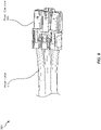
- FIG. 5 and 6 illustrate example apparatuses 500 and 600, respectively, for protecting power connectors against high-power arcing.
- apparatuses 500 and 600 may include and/or represent power connector 104, power cable 110, and/or screws 308(1) and 308(2).
- apparatuses 500 and 600 in FIGS. 5 and 6 may implement and/or incorporate any of the technologies, configurations, designs, components, and/or features described above in connection with the apparatuses illustrated in FIGS. 1-4 .
- FIGS. 7 and 8 illustrate example systems 700 and 800 for protecting power connectors against high-power arcing.
- systems 700 and 800 may include and/or represent power enclosure 102, power connector 104, power cable 110, power supply module 112, and/or screws 308(1) and 308(2).
- systems 700 and 800 may also include and/or represent a computing device 702 that houses certain features, including power supply module 112 and/or power enclosure 102.
- Systems 700 and 800 in FIGS. 7 and 8 respectively, may implement and/or incorporate any of the technologies, configurations, designs, components, and/or features described above in connection with the apparatuses illustrated in FIGS. 1-6 .
- computing device 702 may include and/or represent the chassis of a telecommunications device (such as a router or switch).
- system 700 in FIG. 7 may demonstrate and/or represent a situation in which power connector 104 is currently in the processing of being installed into and/or mated with power enclosure 102.
- system 700 in FIG. 7 may demonstrate and/or represent a situation in which power connector 104 is currently in the processing of being uninstalled and/or removed from power enclosure 102.
- system 800 in FIG. 8 may demonstrate and/or represent a situation in which power connector 104 is fully installed into and/or mated with power enclosure 102.
- FIG. 9 illustrates an example apparatus 900 for protecting power connectors against high-power arcing.
- apparatus 900 may include and/or represent power connector 104 electrically coupled to power cable 110, which facilitates carrying electric current to power supply module 112 via power enclosure 102.
- apparatus 900 in FIG. 9 may implement and/or incorporate any of the technologies, configurations, designs, components, and/or features described above in connection with the apparatuses illustrated in FIGS. 1-8 .
- FIG. 10 illustrates an example mechanical handle 1000 dimensioned to couple to and/or partially cover power connector 104.
- mechanical handle 1000 may be equipped with screws 308(1) and 308(2).
- mechanical handle 1000 in FIG. 10 may implement and/or incorporate any of the technologies, configurations, designs, components, and/or features described above in connection with the apparatuses illustrated in FIGS. 1-9 .
- mechanical handle 1000 may facilitate retrofitting apparatus 900, power connector 104, and/or power cable 110 for protecting against high-power arcing.
- mechanical handle 1000 may attach and/or couple to power connector 104 via one or more screws, fasteners, and/or adhesives.
- Mechanical handle 1000 may include and/or form any suitable shape to facilitate and/or achieve the desired retrofitting.
- mechanical handle 1000 may be of any suitable sizes and/or dimensions to facilitate and/or achieve the desired retrofitting.
- Mechanical handle 1000 may include and/or contain any of a variety of materials. Examples of such materials include, without limitation, plastics, ceramics, polymers, composites, rubbers, metals, combinations or variations of one or more of the same, and/or any other suitable materials.
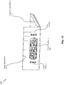
- FIG. 11 illustrates an example apparatus 1100 for protecting power connectors against high-power arcing.
- apparatus 1100 may include and/or represent power connector 104, power cable 110, mechanical handle 1000, and/or screws 308(1) and 308(2).
- apparatus 1100 in FIG. 11 may implement and/or incorporate any of the technologies, configurations, designs, components, and/or features described above in connection with the apparatuses illustrated in FIGS. 1-10 .
- mechanical handle 1000 may be coupled and/or attached to power connector 104.
- screws 308(1) and 308(2) may secure power connector 104 to power enclosure 102 and/or engage one or more power switches electrically coupled to power enclosure 102.
- FIG. 12 illustrates an example apparatus 1200 for protecting power connectors against high-power arcing.
- apparatus 1200 may include and/or represent power enclosure 102 coupled to and/or incorporated in power supply module 112.
- apparatus 1200 in FIG. 12 may implement and/or incorporate any of the technologies, configurations, designs, components, and/or features described above in connection with the apparatuses illustrated in FIGS. 1-11 .
- power supply module 112 may include and/or contain electronic plates 1202(1) and 1202(2) positioned to facilitate contact with screws 308(1) and 308(2), respectively, of power connector 104 once fully mated with power enclosure 102.
- the contact between screw 308(1) and electronic plate 1202(1) may cause a signal to propagate to power enclosure 102. Additionally or alternatively, the contact between screw 308(2) and electronic plate 1202(2) may cause a signal to propagate to power enclosure 102. In one example, the signal may be indicative of power connector 104 being fully mated with power enclosure 102. In response to the signal, power enclosure 102 may enable electric current to flow from power connector 104 to power supply module 112 via power enclosure 102.
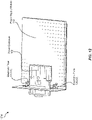
- FIG. 13 illustrates an example apparatus 1300 for protecting power connectors against high-power arcing.
- apparatus 1300 may include and/or represent power enclosure 102 coupled to and/or incorporated in power supply module 112 of computing device 702.
- apparatus 1300 in FIG. 13 may implement and/or incorporate any of the technologies, configurations, designs, components, and/or features described above in connection with the apparatuses illustrated in FIGS. 1-12 .
- computing device 702, power supply module 112, and/or power enclosure 102 may include and/or form holes 1302(1) and 1302(2) fitted to accept screws 308(1) and 308(2) to secure power connector 104 to power enclosure 102 and/or to enable the flow of electric current from power connector 104 to power supply 112 via power enclosure 102.
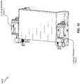
- FIG. 14 illustrates an example locking assembly 1400 designed and/or configured to lock power connector 104 in place when fully and/or properly mated to power enclosure 102.
- locking assembly 1400 may include and/or incorporate locking solenoids 1402(1) and 1402(2).
- locking assembly 1400 may implement and/or incorporate any of the technologies, configurations, designs, components, and/or features described above in connection with the apparatuses illustrated in FIGS. 1-12 .
- locking assembly 1400 may secure and/or lock power connector 104 in place by latching onto screws 308(1) and 308(2) via locking solenoids 1402(1) and 1402(2), respectively.
- locking assembly 1400 may facilitate retrofitting all or portions of apparatus 1200 or 1300 for protecting against high-power arcing.
- locking assembly 1400 may be attached and/or coupled to power supply module 112 atop power enclosure 102 via one or more screws, fasteners, and/or adhesives. In this position, locking assembly 1400 may be able to use locking solenoids 1402(1) and 1402(2) to secure screws 308(1) and 308(2), respectively, to ensure a full and/or proper mating between power connector 104 and power enclosure 102.
- Locking assembly 1400 may include and/or form any suitable shape to facilitate and/or achieve the desired retrofitting.
- locking assembly 1400 may be of any suitable sizes and/or dimensions to facilitate and/or achieve the desired retrofitting.
- Locking assembly 1400 may include and/or contain any of a variety of materials. Examples of such materials include, without limitation, plastics, ceramics, polymers, composites, rubbers, metals, combinations or variations of one or more of the same, and/or any other suitable materials.
- FIG. 15 illustrates an example apparatus 1500 for protecting power connectors against high-power arcing.
- apparatus 1500 may include and/or represent power enclosure 102 coupled to and/or incorporated in power supply module 112 of computing device 702.
- apparatus 1500 in FIG. 15 may implement and/or incorporate any of the technologies, configurations, designs, components, and/or features described above in connection with the apparatuses illustrated in FIGS. 1-14 .
- FIGS. 16 , 17 , and 18 illustrate example systems 1600, 1700, and 1800, respectively, for protecting power connectors against high-power arcing.
- systems 1600, 1700, and 1800 may include and/or represent power enclosure 102, power connector 104, power supply module 112, screws 308(1) and 308(2), and/or locking assembly 1400.
- systems 1600, 1700, and 1800 may implement and/or incorporate any of the technologies, configurations, designs, components, and/or features described above in connection with the apparatuses illustrated in FIGS. 1-15 .
- system 1600 may demonstrate and/or represent a situation in which screw 308(2) of power connector 104 has yet to be tightened and/or secured to power enclosure 102.
- system 1700 may demonstrate and/or a situation in which screw 308(2) of power connector 104 is currently in the processing of being tightened and/or rotated with respect to power enclosure 102.
- system 1800 may demonstrate and/or represent a situation in which screw 308(2) of power connector 104 has been fully tightened and/or secured to power enclosure 102. As a result, power connector 104 may be been fully and/or properly installed and/or mated to power enclosure 102.
- FIG. 19 illustrates an example mechanical handle 1900 dimensioned to couples to and/or partially cover power connector 104.
- mechanical handle 1000 may be equipped with a latch 1902.
- mechanical handle 1900 in FIG. 19 may implement and/or incorporate any of the technologies, configurations, designs, components, and/or features described above in connection with the apparatuses illustrated in FIGS. 1-18 .
- mechanical handle 1900 may facilitate retrofitting apparatus 900, power connector 104, and/or power cable 110 for protecting against high-power arcing.
- mechanical handle 1900 may attach and/or couple to power connector 104 via one or more screws, fasteners, and/or adhesives.
- FIGS. 20 and 21 illustrates example apparatuses 2000 and 2100, respectively, for protecting power connectors against high-power arcing.
- apparatuses 2000 and 2100 may include and/or represent power connector 104, power cable 110, and/or mechanical handle 1900 with latch 1902.
- apparatuses 2000 and 2100 may implement and/or incorporate any of the technologies, configurations, designs, components, and/or features described above in connection with the apparatuses illustrated in FIGS. 1-19 .
- mechanical handle 1900 may be coupled and/or attached to power connector 104.
- latch 1902 may secure power connector 104 to power enclosure 102 and/or engage one or more power switches electrically coupled to power enclosure 102.
- FIG. 22 illustrates an example apparatus 2200 for protecting power connectors against high-power arcing.
- apparatus 2200 may include and/or represent power enclosure 102 coupled to and/or incorporated in power supply module 112.
- apparatus 2200 in FIG. 22 may implement and/or incorporate any of the technologies, configurations, designs, components, and/or features described above in connection with the apparatuses illustrated in FIGS. 1-21 .
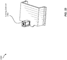
- FIG. 23 illustrates an example locking assembly 2300 designed and/or configured to lock power connector 104 in place when fully and/or properly mated to power enclosure 102.
- locking assembly 2300 may include and/or incorporate a locking solenoid 2302.
- locking assembly 2300 may implement and/or incorporate any of the technologies, configurations, designs, components, and/or features described above in connection with the apparatuses illustrated in FIGS. 1-22 .
- locking assembly 2300 may secure and/or lock power connector 104 in place by way of latch 1902 of mechanical handle 1900.
- locking assembly 2300 may facilitate retrofitting all or portions of apparatus 2200 for protecting against high-power arcing.
- locking assembly 2300 may be attached and/or coupled to power supply module 112 atop power enclosure 102 via one or more screws, fasteners, and/or adhesives. In this position, locking assembly 2300 may be able to use locking solenoid 2302 to secure latch 1902 to ensure a full and/or proper mating between power connector 104 and power enclosure 102.
- Locking assembly 2300 may include and/or form any suitable shape to facilitate and/or achieve the desired retrofitting.
- locking assembly 2300 may be of any suitable sizes and/or dimensions to facilitate and/or achieve the desired retrofitting.
- Locking assembly 2300 may include and/or contain any of a variety of materials. Examples of such materials include, without limitation, plastics, ceramics, polymers, composites, rubbers, metals, combinations or variations of one or more of the same, and/or any other suitable materials.
- FIG. 24 illustrates an example apparatus 2400 for protecting power connectors against high-power arcing.
- apparatus 2400 may include and/or represent power enclosure 102 coupled to and/or incorporated in power supply module 112 of computing device 702.
- apparatus 2400 in FIG. 24 may implement and/or incorporate any of the technologies, configurations, designs, components, and/or features described above in connection with the apparatuses illustrated in FIGS. 1-23 .
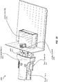
- FIGS. 25 and 26 illustrate example systems 2500 and 2600, respectively, for protecting power connectors against high-power arcing.
- systems 2500 and 2600 may include and/or represent power enclosure 102, power connector 104, power supply module 112, mechanical handle 1900, and/or locking assembly 2300.
- systems 2500 and 2600 may implement and/or incorporate any of the technologies, configurations, designs, components, and/or features described above in connection with the apparatuses illustrated in FIGS. 1-24 .
- system 2500 may demonstrate and/or represent a situation in which latch 1902 of mechanical handle 1900 has yet to reach locking solenoid 2302 as power connector 104 is installed into and/or mated with power enclosure 102. In another example, system 2500 may demonstrate and/or represent a situation in which latch 1902 of mechanical handle 1900 has left locking solenoid 2302 as power connector 104 is uninstalled and/or mated from power enclosure 102. Additionally or alternatively, system 2600 may demonstrate and/or represent a situation in which latch 1902 of mechanical handle 1900 is fully engaged with locking solenoid 2302 and power connector 104 is fully and/or properly mated with power enclosure 102.
- any of the apparatuses and/or systems disclosed herein may include and/or represent circuitry and/or processing devices that are not expressly illustrated and/or labelled in FIGS. 1-26 .
- any of the apparatuses and/or systems disclosed herein may include and/or represent a physical processing device that detects and/or determines whether or not power switch 106 is engaged by feature 108 of power connector 104.
- the processing device may cause and/or direct power enclosure 102 to close a circuit that enables the flow of electric current from power connector 104 to power supply module 112 via power enclosure 102.
- the processing device may cause and/or direct power enclosure 102 to open the circuit to disable the flow of electric current from power connector 104 to power supply module 112 via power enclosure 102.
- FIG. 27 is a flow diagram of an example method 2700 for protecting power connectors against high-power arcing.
- Method 2700 may include the step of electrically coupling a power enclosure to a power supply module of a computing device (2710).
- Step 2710 may be performed in a variety of ways, including any of those described above in connection with FIGS. 1-26 .
- a computing equipment manufacturer or subcontractor may manufacture a power supply module for a network device (such as a router or switch).
- the computing equipment manufacturer or subcontractor may electrically couple a power enclosure to the power supply module of the network device.
- Method 2700 may also include the step of electrically coupling at least one power switch to the power enclosure, the power switch being configured for engagement by at least one feature of the power connector while the power connector is fully mated with the power enclosure (2720).
- Step 2720 may be performed in a variety of ways, including any of those described above in connection with FIGS. 1-26 .
- the computing equipment manufacturer or subcontractor may electrically couple at least one power switch to the power enclosure.
- the power switch may be configured for engagement by at least one feature of the power connector while the power connector is fully mated with the power enclosure.
- the power switch when engaged by the feature of the power connector, the power switch may enable electric current to flow from the power connector to the power supply module via the power enclosure (2720(A)). In contrast, when not engaged by the feature of the power connector, the power switch may prevent electric current from flowing to the power supply module via the power enclosure (2720(B)).
- an apparatus that includes a power enclosure electrically coupled to a power supply module of a computing device, a power connector that is electrically coupled to a power cable that facilitates carrying electric current to the power supply module via the power enclosure and is dimensioned to mate with the power enclosure, and at least one power switch that is electrically coupled to the power enclosure, is configured to be engaged by at least one feature of the power connector while the power connector is fully mated with the power enclosure, and when engaged by the feature of the power connector, enables electric current to flow from the power connector to the power supply module via the power enclosure.
- each block diagram component, flowchart step, operation, and/or component described and/or illustrated herein may be implemented, individually and/or collectively, using a wide range of hardware, software, or firmware (or any combination thereof) configurations.
- any disclosure of components contained within other components should be considered as being by way of example in nature since many other architectures can be implemented to achieve the same functionality.
Landscapes
- Engineering & Computer Science (AREA)
- Theoretical Computer Science (AREA)
- Physics & Mathematics (AREA)
- General Engineering & Computer Science (AREA)
- General Physics & Mathematics (AREA)
- Electromagnetism (AREA)
- Computer Hardware Design (AREA)
- Power Engineering (AREA)
- Human Computer Interaction (AREA)
- Details Of Connecting Devices For Male And Female Coupling (AREA)
- Connector Housings Or Holding Contact Members (AREA)
- Protection Of Static Devices (AREA)
Abstract
Description
- In today's world of vast computing technology, telecommunications devices are continually evolving to meet customers' needs and/or demands. For example, telecommunications equipment manufacturers often undertake efforts to increase the bitrates of their telecommunications devices. To do so, these manufacturers may also need to increase the power consumption of their telecommunications devices. Such increased power consumption may involve and/or necessitate power collectively drawn and/or sourced through multiple power supplies.
- These telecommunications devices may include and/or provide power connection points to which high-power connecters are installed and/or removed. For example, an administrator may install and/or attach a high-power Direct Current (DC) connector to a connection point on a telecommunications device. Later, the administrator may remove and/or detach the high-power DC connector from the connection point while electric current is flowing. Unfortunately, by removing and/or detaching the high-power DC connector while electric current is flowing, the administrator may create a situation that results in electrical arcing between the high-power DC connector and the connection point on the telecommunications device.
- Such arcing may pose and/or present a risk of damage to the telecommunications device, a risk of fire, a risk of electrocution and/or burns to the administrator, and/or a risk of damage to the reputation and/or brand of the manufacturer of the telecommunications device. The instant disclosure, therefore, identifies and addresses a need for apparatuses, systems, and methods for protecting power connectors against high-power arcing.
- Particular aspects are set out in the appended independent claims. Various optional embodiments are set out in the dependent claims.
- As will be described in greater detail below, the instant disclosure generally relates to apparatuses, systems, and methods for protecting power connectors against high-power arcing. In one example, an apparatus for accomplishing such a task may include (1) a power enclosure electrically coupled to a power supply module of a computing device, (2) a power connector that (A) is electrically coupled to a power cable that facilitates carrying electric current to the power supply module via the power enclosure and (B) is dimensioned to mate with the power enclosure, and (3) at least one power switch that (A) is electrically coupled to the power enclosure, (B) is configured to be engaged by at least one feature of the power connector while the power connector is fully mated with the power enclosure, and when engaged by the feature of the power connector, (C) enables electric current to flow from the power connector to the power supply module via the power enclosure.
- Similarly, a system for accomplishing such a task may include (1) a power supply module, (2) a power enclosure electrically coupled to the power supply module, (3) a power connector that (A) is electrically coupled to a power cable that facilitates carrying electric current to the power supply module via the power enclosure and (B) is dimensioned to mate with the power enclosure, (4) at least one power switch that (A) is electrically coupled to the power enclosure, (B) is configured to be engaged by at least one feature of the power connector while the power connector is fully mated with the power enclosure, and when engaged by the feature of the power connector, (C) enables electric current to flow from the power connector to the power supply module via the power enclosure.
- A corresponding method may include (1) electrically coupling a power enclosure to a power supply module of a computing device and (2) electrically coupling at least one power switch to the power enclosure, the power switch being configured for engagement by at least one feature of the power connector while the power connector is fully mated with the power enclosure such that (A) when engaged by the feature of the power connector, the power switch enables electric current to flow from the power connector to the power supply module via the power enclosure and (B) when not engaged by the feature of the power connector, the power switch prevents the electric current from flowing to the power supply module via the power enclosure.
- Features from any of the above-mentioned embodiments may be used in combination with one another in accordance with the general principles described herein. These and other embodiments, features, and advantages will be more fully understood upon reading the following detailed description in conjunction with the accompanying drawings and claims.
- The accompanying drawings illustrate a number of example embodiments and are a part of the specification. Together with the following description, these drawings demonstrate and explain various principles of the instant disclosure.
-
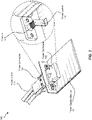
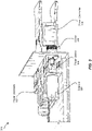
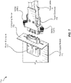
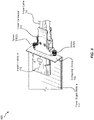
FIG. 1 is an illustration of an example apparatus for protecting power connectors against high-power arcing. -
FIG. 2 is an illustration of an example apparatus for protecting power connectors against high-power arcing. -
FIG. 3 is an illustration of an example apparatus for protecting power connectors against high-power arcing. -
FIG. 4 is an illustration of an example apparatus for protecting power connectors against high-power arcing. -
FIG. 5 is an illustration of an example apparatus for protecting power connectors against high-power arcing. -
FIG. 6 is an illustration of an example apparatus for protecting power connectors against high-power arcing. -
FIG. 7 is an illustration of an example system for protecting power connectors against high-power arcing. -
FIG. 8 is an illustration of an example system for protecting power connectors against high-power arcing. -
FIG. 9 is an illustration of an example apparatus for protecting power connectors against high-power arcing. -
FIG. 10 is an illustration of an example apparatus for protecting power connectors against high-power arcing. -
FIG. 11 is an illustration of an example apparatus for protecting power connectors against high-power arcing. -
FIG. 12 is an illustration of an example apparatus for protecting power connectors against high-power arcing. -
FIG. 13 is an illustration of an example apparatus for protecting power connectors against high-power arcing. -
FIG. 14 is an illustration of an example apparatus for protecting power connectors against high-power arcing. -
FIG. 15 is an illustration of an example apparatus for protecting power connectors against high-power arcing. -
FIG. 16 is an illustration of an example system for protecting power connectors against high-power arcing. -
FIG. 17 is an illustration of an example system for protecting power connectors against high-power arcing. -
FIG. 18 is an illustration of an example system for protecting power connectors against high-power arcing. -
FIG. 19 is an illustration of an example apparatus for protecting power connectors against high-power arcing. -
FIG. 20 is an illustration of an example apparatus for protecting power connectors against high-power arcing. -
FIG. 21 is an illustration of an example apparatus for protecting power connectors against high-power arcing. -
FIG. 22 is an illustration of an example apparatus for protecting power connectors against high-power arcing. -
FIG. 23 is an illustration of an example apparatus for protecting power connectors against high-power arcing. -
FIG. 24 is an illustration of an example apparatus for protecting power connectors against high-power arcing. -
FIG. 25 is an illustration of an example system for protecting power connectors against high-power arcing. -
FIG. 26 is an illustration of an example system for protecting power connectors against high-power arcing. -
FIG. 27 is a flow diagram of an example method for protecting power connectors against high-power arcing. - Throughout the drawings, identical reference characters and descriptions indicate similar, but not necessarily identical, elements. While the example embodiments described herein are susceptible to various modifications and alternative forms, specific embodiments have been shown by way of example in the drawings and will be described in detail herein. However, the example embodiments described herein are not intended to be limited to the particular forms disclosed. Rather, the instant disclosure covers all modifications, equivalents, and alternatives falling within the scope of the appended claims.
- The present disclosure describes various apparatuses, systems, and methods for protecting power connectors against high-power arcing. As will be explained in greater detail below, embodiments of the instant disclosure may prevent and/or eliminate dangerous situations in which arcing occurs between high-power DC connectors and connection points on telecommunications devices. By doing so, these embodiments may mitigate various risks that result from such arching, including fire, electrocution or burns, damage to equipment, and/or damage to the reputation and/or brand of the equipment manufacturer.
- The following will provide, with reference to
FIGS. 1-26 , detailed descriptions of example components, apparatuses, systems, configurations, and/or implementations for protecting power connectors against high-power arcing. In addition, the discussion corresponding toFIG. 27 will provide a detailed description of an example method for protecting power connectors against high-power arcing. -
FIG. 1 illustrates anexample apparatus 100 for protecting power connectors against high-power arcing. As illustrated inFIG. 1 ,apparatus 100 may include and/or represent apower enclosure 102, apower connector 104, apower switch 106, apower cable 110, and/or apower supply module 112. In some examples,power enclosure 102 may be electrically coupled topower supply module 112. In such examples,power connector 104 may be electrically coupled topower cable 110, which facilitates carrying electric current topower supply module 112 viapower enclosure 102. Additionally or alternatively,power connector 104 may be dimensioned to mate withpower enclosure 102. - In some examples,
power switch 106 may be electrically coupled topower enclosure 102. In such examples,power switch 106 may be configured and/or designed to be engaged by afeature 108 ofpower connector 104 whilepower connector 104 is fully mated with and/or topower enclosure 102. Additionally or alternatively, when engaged byfeature 108 ofpower connector 104,power switch 106 may enable electric current to flow frompower connector 104 topower supply module 112 viapower enclosure 102. - In some examples,
power enclosure 102 and/orpower connector 104 may include and/or represent a female power receptacle and/or housing designed to accept and/or interface with a male power connector. Additionally or alternatively,power enclosure 102 and/orpower connector 104 may include and/or represent a male power connector designed to accept and/or interface with a female power connector. In one example,power enclosure 102 and/orpower connector 104 may be designed and/or fitted to mate and/or interface with one another. - In some examples,
power enclosure 102,power connector 104,power switch 106,power cable 110, and/orpower supply module 112 may each include and/or contain certain electrically conductive layers and/or traces. Such conductive layers and/or traces may include and/or represent electrically conductive materials. Examples of such electrically conductive materials include, without limitation, copper, aluminum, silver, gold, metals, alloys of one or more of the same, combinations or variations of one or more of the same, and/or any other suitable materials. - In some examples,
power enclosure 102,power connector 104,power switch 106,power cable 110, and/orpower supply module 112 may each also include and/or contain certain non-conductive and/or insulative materials. Examples of such non-conductive and/or insulative materials include, without limitation, plastics, ceramics, polymers, composites, rubbers, dielectrics, combinations or variations of one or more of the same, and/or any other suitable materials. - In some examples,
power enclosure 102,power connector 104,power cable 110, and/orpower supply module 112 may include and/or contain electrically conductive materials designed and/or intended to carry, transfer, and/or deliver electric current frompower cable 110 topower supply module 112 viapower connector 104 andpower enclosure 102. In such examples, the electric current carried, transferred, and/or delivered by those conductive materials may be direct current or alternating current. In one example, the electric current may be guided and/or directed towardpower supply module 112 by certain non-conductive and/or insulative materials included and/or contained inpower enclosure 102,power connector 104,power cable 110, and/orpower supply module 112. - In some examples,
power switch 106 may include and/or represent an electronic switch, an electronic plate, and/or a button. In such examples, when engaged byfeature 108 ofpower connector 104,power switch 106 may causepower enclosure 102 to allow and/or enable the flow of electric current carried bypower cable 110 to reachpower supply module 112 viapower connector 104 andpower enclosure 102. Additionally or alternatively, when engaged byfeature 108 ofpower connector 104,power switch 106 may effectively close a circuit that enables the flow of electric current frompower cable 110 to reachpower supply module 112 viapower connector 104 andpower enclosure 102. By doing so,power switch 106 may prevent and/or protect against electrical arcing aspower connector 104 is inserted and/or installed intopower enclosure 102. - In contrast, when not engaged by
feature 108 ofpower connector 104,power switch 106 may causepower enclosure 102 to disallow, disable, and/or prevent electric current from flowing frompower cable 110 topower supply module 112 viapower connector 104 and/orpower enclosure 102. Additionally or alternatively, when not engaged byfeature 108 ofpower connector 104,power switch 106 may effectively open a circuit that disables the flow of electric current frompower cable 110 topower supply module 112 viapower connector 104 and/orpower enclosure 102. By doing so,power switch 106 may prevent and/or protect against electrical arcing aspower connector 104 is removed and/or uninstalled frompower enclosure 102. - In some examples, feature 108 of
power connector 104 may include and/or represent a screw that interfaces and/or makes contact withpower switch 106, thereby engagingpower switch 106 to facilitate the flow of electric current acrosspower enclosure 102,power connector 104,power cable 110, and/orpower supply module 112. For example, feature 108 may include and/or represent a thumb screw whose tip engagespower switch 106 oncepower connector 104 andpower enclosure 102 are fully and/or properly mated together. Additional examples offeature 108 include, without limitation, latches, members, pegs, pins, arms, bolts, screws, fasteners, combinations of one or more of the same, and/or any other suitable features. - In some examples, a full and/or proper mating between
power connector 104 andpower enclosure 102 may involve and/or entail securely fastening one to the other and/or limiting any gaps and/or space between the conductive features incorporated intopower connector 104 andpower enclosure 102. Accordingly, such a full and/or proper mating betweenpower connector 104 andpower enclosure 102 may mitigate, eliminate, and/or prevent the possibility of high-power arcing. - Continuing with this example, the thumb screw may be dimensioned such that its tip is unable to reach and/or engage
power switch 106 unlesspower connector 104 andpower enclosure 102 are fully and/or properly mated together. Only then, in this example, may the thumb screw engagepower switch 106 for the purpose of activating the flow of electric current acrosspower enclosure 102,power connector 104,power cable 110, and/orpower supply module 112. As a result, this configuration and/or design may mitigate various risks that result from high-power arching, including fire, electrocution or burns, damage to equipment, and/or damage to the reputation and/or brand of the equipment manufacturer. -
Power enclosure 102,power connector 104,power switch 106, feature 108,power cable 110, and/orpower supply module 112 may each include and/or form any suitable shape. In addition,power enclosure 102,power connector 104,power switch 106, feature 108,power cable 110, and/orpower supply module 112 may be of any suitable sizes and/or dimensions. -
FIG. 2 illustrates anexample apparatus 200 for protecting power connectors against high-power arcing. Likeapparatus 100 inFIG. 1 ,apparatus 200 inFIG. 2 may include and/or representpower enclosure 102,power connector 104,power switch 106,power cable 110, and/orpower supply module 112. In some examples,apparatus 200 inFIG. 2 may implement and/or incorporate any of the technologies, configurations, designs, components, and/or features described above in connection withapparatus 100 inFIG. 1 . - In some examples,
power enclosure 102 may include and/or represent one or more electrical contacts. In such examples,power connector 104 may include and/or represent one or more electrical contacts that electrically couple with and/or to the electrical contacts ofpower enclosure 102. This electrical coupling may enable electric current to flow frompower cable 110 topower supply module 112 viapower connector 104 andpower enclosure 102. - In some examples,
power switch 106 may change from an "off" state in which feature 108 ofpower connector 104 is not engaged to an "on" state in which feature 108 ofpower connector 104 is engaged. This change from the "off" state to the "on" state may occur only afterpower connector 104 has been fully and/or properly mated with and/or installed topower enclosure 102. Upon changing to the "on" state,power switch 106 may enable, activate, and/or initiate the flow of electric current frompower connector 104 topower supply module 112 viapower enclosure 102. By doing so,power switch 106 may facilitate powering, activating, and/or energizingpower supply module 112 safely without the possibility of electrical arcing. - In other examples,
power switch 106 may change from an "on" state in which feature 108 ofpower connector 104 is engaged to an "off" state in which feature 108 ofpower connector 104 is not engaged. Upon changing to the "off" state,power switch 106 may interrupt, disable, and/or stop the flow of electric current frompower connector 104 topower supply module 112 viapower enclosure 102 to prevent electrical arcing aspower connector 104 is removed and/or uninstalled frompower enclosure 102. - In some examples,
power enclosure 102 may include and/or form one or more holes fitted to accept one ormore features 108 ofpower connector 104. For example,power enclosure 102 may include and/or form one or more holes fitted to accept one or more thumb screws ofpower connector 104. In one example,power switch 106 may include and/or represent a plate positioned to facilitate contact with a screw ofpower connector 104 once fully mated withpower enclosure 102. - In some examples, the contact between the screw and the plate may cause a signal to propagate to
power enclosure 102. In such examples, the signal may be indicative ofpower connector 104 being fully mated withpower enclosure 102. In response to the signal,power enclosure 102 may enable electric current to flow frompower connector 104 topower supply module 112 viapower enclosure 102. - In some examples, the screw may effectively close a circuit via the plate while
power connector 104 is fully mated withpower enclosure 102. In such examples, the closed circuit may causepower enclosure 102 to enable electric current to flow frompower connector 104 topower supply module 112 viapower enclosure 102. - In one example,
power switch 106 may include and/or represent an electronic switch and/or button positioned to facilitate contact with a screw ofpower connector 104 once fully mated withpower enclosure 102. For example, the screw ofpower connector 104 may compress the electronic switch and/or button whenpower connector 104 is fully and/or properly mated withpower enclosure 102. In this example, the compression of the switch and/or button may cause a signal to propagate topower enclosure 102. The signal may be indicative ofpower connector 104 being fully mated withpower enclosure 102. In response to the signal,power enclosure 102 may enable electric current to flow frompower connector 104 topower supply module 112 viapower enclosure 102. -
FIG. 3 illustrates anexample apparatus 300 for protecting power connectors against high-power arcing. Likeapparatus 200 inFIG. 2 ,apparatus 300 inFIG. 3 may include and/or representpower enclosure 102,power connector 104,power switch 106,power cable 110, and/orpower supply module 112. In some examples,apparatus 300 inFIG. 3 may implement and/or incorporate any of the technologies, configurations, designs, components, and/or features described above in connection with the apparatuses illustrated inFIGS. 1 and2 . - In some examples,
power switch 106 may include, involve, and/or represent asolenoid 306 that locks and/or retains ascrew 308 in place while electric current is flowing frompower connector 104 topower supply module 112 viapower enclosure 102. In one example, whenscrew 308 is fully locked and/or retained bysolenoid 306,power switch 106 may enable and/or activate the flow of electrical current frompower connector 104 topower supply module 112 viapower enclosure 102. Additionally or alternatively, whenscrew 308 is not fully locked and/or retained bysolenoid 306,power switch 106 may disable and/or deactivate the flow of electrical current frompower connector 104 topower supply module 112 viapower enclosure 102. -
FIG. 4 illustrates anexample apparatus 400 for protecting power connectors against high-power arcing. As illustrated inFIG. 4 ,apparatus 400 may include and/or representpower enclosure 102,power connector 104,power supply module 112, screws 308(1) and 308(2), and/or solenoids 306(1) and 306(2). In some examples,apparatus 400 inFIG. 4 may implement and/or incorporate any of the technologies, configurations, designs, components, and/or features described above in connection with the apparatuses illustrated inFIGS. 1-3 . -
FIG. 5 and6 illustrateexample apparatuses FIGS. 5 and6 ,apparatuses power connector 104,power cable 110, and/or screws 308(1) and 308(2). In some examples,apparatuses FIGS. 5 and6 , respectively, may implement and/or incorporate any of the technologies, configurations, designs, components, and/or features described above in connection with the apparatuses illustrated inFIGS. 1-4 . -
FIGS. 7 and8 illustrateexample systems FIGS. 7 and8 ,systems power enclosure 102,power connector 104,power cable 110,power supply module 112, and/or screws 308(1) and 308(2). In some examples,systems computing device 702 that houses certain features, includingpower supply module 112 and/orpower enclosure 102.Systems FIGS. 7 and8 , respectively, may implement and/or incorporate any of the technologies, configurations, designs, components, and/or features described above in connection with the apparatuses illustrated inFIGS. 1-6 . In one example,computing device 702 may include and/or represent the chassis of a telecommunications device (such as a router or switch). - In one example,
system 700 inFIG. 7 may demonstrate and/or represent a situation in whichpower connector 104 is currently in the processing of being installed into and/or mated withpower enclosure 102. In another example,system 700 inFIG. 7 may demonstrate and/or represent a situation in whichpower connector 104 is currently in the processing of being uninstalled and/or removed frompower enclosure 102. Additionally or alternatively,system 800 inFIG. 8 may demonstrate and/or represent a situation in whichpower connector 104 is fully installed into and/or mated withpower enclosure 102. -
FIG. 9 illustrates anexample apparatus 900 for protecting power connectors against high-power arcing. As illustrated inFIG. 9 ,apparatus 900 may include and/or representpower connector 104 electrically coupled topower cable 110, which facilitates carrying electric current topower supply module 112 viapower enclosure 102. In some examples,apparatus 900 inFIG. 9 may implement and/or incorporate any of the technologies, configurations, designs, components, and/or features described above in connection with the apparatuses illustrated inFIGS. 1-8 . -
FIG. 10 illustrates an examplemechanical handle 1000 dimensioned to couple to and/or partially coverpower connector 104. As illustrated inFIG. 10 ,mechanical handle 1000 may be equipped with screws 308(1) and 308(2). In some examples,mechanical handle 1000 inFIG. 10 may implement and/or incorporate any of the technologies, configurations, designs, components, and/or features described above in connection with the apparatuses illustrated inFIGS. 1-9 . - In some examples,
mechanical handle 1000 may facilitate retrofittingapparatus 900,power connector 104, and/orpower cable 110 for protecting against high-power arcing. In one example,mechanical handle 1000 may attach and/or couple topower connector 104 via one or more screws, fasteners, and/or adhesives. -
Mechanical handle 1000 may include and/or form any suitable shape to facilitate and/or achieve the desired retrofitting. In addition,mechanical handle 1000 may be of any suitable sizes and/or dimensions to facilitate and/or achieve the desired retrofitting. -
Mechanical handle 1000 may include and/or contain any of a variety of materials. Examples of such materials include, without limitation, plastics, ceramics, polymers, composites, rubbers, metals, combinations or variations of one or more of the same, and/or any other suitable materials. -
FIG. 11 illustrates anexample apparatus 1100 for protecting power connectors against high-power arcing. As illustrated inFIG. 11 ,apparatus 1100 may include and/or representpower connector 104,power cable 110,mechanical handle 1000, and/or screws 308(1) and 308(2). In some examples,apparatus 1100 inFIG. 11 may implement and/or incorporate any of the technologies, configurations, designs, components, and/or features described above in connection with the apparatuses illustrated inFIGS. 1-10 . In one example,mechanical handle 1000 may be coupled and/or attached topower connector 104. In this example, screws 308(1) and 308(2) may securepower connector 104 topower enclosure 102 and/or engage one or more power switches electrically coupled topower enclosure 102. -
FIG. 12 illustrates anexample apparatus 1200 for protecting power connectors against high-power arcing. As illustrated inFIG. 12 ,apparatus 1200 may include and/or representpower enclosure 102 coupled to and/or incorporated inpower supply module 112. In some examples,apparatus 1200 inFIG. 12 may implement and/or incorporate any of the technologies, configurations, designs, components, and/or features described above in connection with the apparatuses illustrated inFIGS. 1-11 . In one example,power supply module 112 may include and/or contain electronic plates 1202(1) and 1202(2) positioned to facilitate contact with screws 308(1) and 308(2), respectively, ofpower connector 104 once fully mated withpower enclosure 102. - In some examples, the contact between screw 308(1) and electronic plate 1202(1) may cause a signal to propagate to
power enclosure 102. Additionally or alternatively, the contact between screw 308(2) and electronic plate 1202(2) may cause a signal to propagate topower enclosure 102. In one example, the signal may be indicative ofpower connector 104 being fully mated withpower enclosure 102. In response to the signal,power enclosure 102 may enable electric current to flow frompower connector 104 topower supply module 112 viapower enclosure 102. -
FIG. 13 illustrates anexample apparatus 1300 for protecting power connectors against high-power arcing. As illustrated inFIG. 13 ,apparatus 1300 may include and/or representpower enclosure 102 coupled to and/or incorporated inpower supply module 112 ofcomputing device 702. In some examples,apparatus 1300 inFIG. 13 may implement and/or incorporate any of the technologies, configurations, designs, components, and/or features described above in connection with the apparatuses illustrated inFIGS. 1-12 . In one example,computing device 702,power supply module 112, and/orpower enclosure 102 may include and/or form holes 1302(1) and 1302(2) fitted to accept screws 308(1) and 308(2) to securepower connector 104 topower enclosure 102 and/or to enable the flow of electric current frompower connector 104 topower supply 112 viapower enclosure 102. -
FIG. 14 illustrates anexample locking assembly 1400 designed and/or configured to lockpower connector 104 in place when fully and/or properly mated topower enclosure 102. As illustrated inFIG. 14 , lockingassembly 1400 may include and/or incorporate locking solenoids 1402(1) and 1402(2). In some examples, lockingassembly 1400 may implement and/or incorporate any of the technologies, configurations, designs, components, and/or features described above in connection with the apparatuses illustrated inFIGS. 1-12 . - In some examples, locking
assembly 1400 may secure and/or lockpower connector 104 in place by latching onto screws 308(1) and 308(2) via locking solenoids 1402(1) and 1402(2), respectively. In one example, lockingassembly 1400 may facilitate retrofitting all or portions ofapparatus assembly 1400 may be attached and/or coupled topower supply module 112 atoppower enclosure 102 via one or more screws, fasteners, and/or adhesives. In this position, lockingassembly 1400 may be able to use locking solenoids 1402(1) and 1402(2) to secure screws 308(1) and 308(2), respectively, to ensure a full and/or proper mating betweenpower connector 104 andpower enclosure 102. - Locking
assembly 1400 may include and/or form any suitable shape to facilitate and/or achieve the desired retrofitting. In addition, lockingassembly 1400 may be of any suitable sizes and/or dimensions to facilitate and/or achieve the desired retrofitting. - Locking
assembly 1400 may include and/or contain any of a variety of materials. Examples of such materials include, without limitation, plastics, ceramics, polymers, composites, rubbers, metals, combinations or variations of one or more of the same, and/or any other suitable materials. -
FIG. 15 illustrates anexample apparatus 1500 for protecting power connectors against high-power arcing. As illustrated inFIG. 15 ,apparatus 1500 may include and/or representpower enclosure 102 coupled to and/or incorporated inpower supply module 112 ofcomputing device 702. In some examples,apparatus 1500 inFIG. 15 may implement and/or incorporate any of the technologies, configurations, designs, components, and/or features described above in connection with the apparatuses illustrated inFIGS. 1-14 . -
FIGS. 16 ,17 , and18 illustrateexample systems FIGS. 16-18 ,systems power enclosure 102,power connector 104,power supply module 112, screws 308(1) and 308(2), and/or lockingassembly 1400. In some examples,systems FIGS. 1-15 . - In one example,
system 1600 may demonstrate and/or represent a situation in which screw 308(2) ofpower connector 104 has yet to be tightened and/or secured topower enclosure 102. In another example,system 1700 may demonstrate and/or a situation in which screw 308(2) ofpower connector 104 is currently in the processing of being tightened and/or rotated with respect topower enclosure 102. Additionally or alternatively,system 1800 may demonstrate and/or represent a situation in which screw 308(2) ofpower connector 104 has been fully tightened and/or secured topower enclosure 102. As a result,power connector 104 may be been fully and/or properly installed and/or mated topower enclosure 102. -
FIG. 19 illustrates an examplemechanical handle 1900 dimensioned to couples to and/or partially coverpower connector 104. As illustrated inFIG. 10 ,mechanical handle 1000 may be equipped with alatch 1902. In some examples,mechanical handle 1900 inFIG. 19 may implement and/or incorporate any of the technologies, configurations, designs, components, and/or features described above in connection with the apparatuses illustrated inFIGS. 1-18 . - In some examples,
mechanical handle 1900 may facilitate retrofittingapparatus 900,power connector 104, and/orpower cable 110 for protecting against high-power arcing. In one example,mechanical handle 1900 may attach and/or couple topower connector 104 via one or more screws, fasteners, and/or adhesives. -
FIGS. 20 and21 illustratesexample apparatuses FIGS. 20 and21 ,apparatuses power connector 104,power cable 110, and/ormechanical handle 1900 withlatch 1902. In some examples,apparatuses FIGS. 1-19 . In one example,mechanical handle 1900 may be coupled and/or attached topower connector 104. In this example,latch 1902 may securepower connector 104 topower enclosure 102 and/or engage one or more power switches electrically coupled topower enclosure 102. -
FIG. 22 illustrates anexample apparatus 2200 for protecting power connectors against high-power arcing. As illustrated inFIG. 22 ,apparatus 2200 may include and/or representpower enclosure 102 coupled to and/or incorporated inpower supply module 112. In some examples,apparatus 2200 inFIG. 22 may implement and/or incorporate any of the technologies, configurations, designs, components, and/or features described above in connection with the apparatuses illustrated inFIGS. 1-21 . -
FIG. 23 illustrates anexample locking assembly 2300 designed and/or configured to lockpower connector 104 in place when fully and/or properly mated topower enclosure 102. As illustrated inFIG. 23 , lockingassembly 2300 may include and/or incorporate alocking solenoid 2302. In some examples, lockingassembly 2300 may implement and/or incorporate any of the technologies, configurations, designs, components, and/or features described above in connection with the apparatuses illustrated inFIGS. 1-22 . - In some examples, locking
assembly 2300 may secure and/or lockpower connector 104 in place by way oflatch 1902 ofmechanical handle 1900. In one example, lockingassembly 2300 may facilitate retrofitting all or portions ofapparatus 2200 for protecting against high-power arcing. In this example, lockingassembly 2300 may be attached and/or coupled topower supply module 112 atoppower enclosure 102 via one or more screws, fasteners, and/or adhesives. In this position, lockingassembly 2300 may be able to use lockingsolenoid 2302 to securelatch 1902 to ensure a full and/or proper mating betweenpower connector 104 andpower enclosure 102. - Locking
assembly 2300 may include and/or form any suitable shape to facilitate and/or achieve the desired retrofitting. In addition, lockingassembly 2300 may be of any suitable sizes and/or dimensions to facilitate and/or achieve the desired retrofitting. - Locking
assembly 2300 may include and/or contain any of a variety of materials. Examples of such materials include, without limitation, plastics, ceramics, polymers, composites, rubbers, metals, combinations or variations of one or more of the same, and/or any other suitable materials. -
FIG. 24 illustrates anexample apparatus 2400 for protecting power connectors against high-power arcing. As illustrated inFIG. 24 ,apparatus 2400 may include and/or representpower enclosure 102 coupled to and/or incorporated inpower supply module 112 ofcomputing device 702. In some examples,apparatus 2400 inFIG. 24 may implement and/or incorporate any of the technologies, configurations, designs, components, and/or features described above in connection with the apparatuses illustrated inFIGS. 1-23 . -
FIGS. 25 and26 illustrateexample systems FIGS. 25 and26 ,systems power enclosure 102,power connector 104,power supply module 112,mechanical handle 1900, and/or lockingassembly 2300. In some examples,systems FIGS. 1-24 . - In one example,
system 2500 may demonstrate and/or represent a situation in which latch 1902 ofmechanical handle 1900 has yet to reach lockingsolenoid 2302 aspower connector 104 is installed into and/or mated withpower enclosure 102. In another example,system 2500 may demonstrate and/or represent a situation in which latch 1902 ofmechanical handle 1900 has left lockingsolenoid 2302 aspower connector 104 is uninstalled and/or mated frompower enclosure 102. Additionally or alternatively,system 2600 may demonstrate and/or represent a situation in which latch 1902 ofmechanical handle 1900 is fully engaged withlocking solenoid 2302 andpower connector 104 is fully and/or properly mated withpower enclosure 102. - The various apparatuses and/or systems disclosed herein may include and/or represent circuitry and/or processing devices that are not expressly illustrated and/or labelled in
FIGS. 1-26 . For example, any of the apparatuses and/or systems disclosed herein may include and/or represent a physical processing device that detects and/or determines whether or notpower switch 106 is engaged byfeature 108 ofpower connector 104. In one example, if the processing device detects thatpower switch 106 is so engaged, the processing device may cause and/ordirect power enclosure 102 to close a circuit that enables the flow of electric current frompower connector 104 topower supply module 112 viapower enclosure 102. Additionally or alternatively, if the processing device detects thatpower switch 106 is not so engaged, the processing device may cause and/ordirect power enclosure 102 to open the circuit to disable the flow of electric current frompower connector 104 topower supply module 112 viapower enclosure 102. -
FIG. 27 is a flow diagram of anexample method 2700 for protecting power connectors against high-power arcing.Method 2700 may include the step of electrically coupling a power enclosure to a power supply module of a computing device (2710).Step 2710 may be performed in a variety of ways, including any of those described above in connection withFIGS. 1-26 . For example, a computing equipment manufacturer or subcontractor may manufacture a power supply module for a network device (such as a router or switch). In this example, as part of the manufacturing process, the computing equipment manufacturer or subcontractor may electrically couple a power enclosure to the power supply module of the network device. -
Method 2700 may also include the step of electrically coupling at least one power switch to the power enclosure, the power switch being configured for engagement by at least one feature of the power connector while the power connector is fully mated with the power enclosure (2720).Step 2720 may be performed in a variety of ways, including any of those described above in connection withFIGS. 1-26 . For example, as part of the manufacturing process, the computing equipment manufacturer or subcontractor may electrically couple at least one power switch to the power enclosure. In this example, the power switch may be configured for engagement by at least one feature of the power connector while the power connector is fully mated with the power enclosure. - As a result, when engaged by the feature of the power connector, the power switch may enable electric current to flow from the power connector to the power supply module via the power enclosure (2720(A)). In contrast, when not engaged by the feature of the power connector, the power switch may prevent electric current from flowing to the power supply module via the power enclosure (2720(B)).
- Therefore, from one perspective, there has been described an apparatus that includes a power enclosure electrically coupled to a power supply module of a computing device, a power connector that is electrically coupled to a power cable that facilitates carrying electric current to the power supply module via the power enclosure and is dimensioned to mate with the power enclosure, and at least one power switch that is electrically coupled to the power enclosure, is configured to be engaged by at least one feature of the power connector while the power connector is fully mated with the power enclosure, and when engaged by the feature of the power connector, enables electric current to flow from the power connector to the power supply module via the power enclosure.
- Further examples of the present disclosure are set out in the following numbered clauses:
-
Clause 1. An apparatus comprising: a power enclosure electrically coupled to a power supply module of a computing device; a power connector that: is electrically coupled to a power cable that facilitates carrying electric current to the power supply module via the power enclosure; and is dimensioned to mate with the power enclosure; and at least one power switch that: is electrically coupled to the power enclosure; is configured to be engaged by at least one feature of the power connector while the power connector is fully mated with the power enclosure; and when engaged by the feature of the power connector, enables electric current to flow from the power connector to the power supply module via the power enclosure. -
Clause 2. The apparatus ofclause 1, wherein the power switch, when not engaged by the feature of the power connector, prevents the electric current from flowing to the power supply module via the power enclosure. - Clause 3. The apparatus of
clause 2, wherein: the power enclosure comprises at least one electrical contact; the power connector comprises at least one additional electrical contact that electrically couples with the electrical contact of the power enclosure to enable the electric current to flow from the power connector to the power supply module; and the power switch: changes from a state in which the feature of the power connector is engaged to an additional state in which the feature of the power connector is not engaged; and upon changing to the additional state, interrupts the flow of electric current from the power connector to the power supply module via the power enclosure to prevent electrical arcing as the power connector is removed from the power enclosure. - Clause 4. The apparatus of
clause - Clause 5. The apparatus of clause 4, wherein the electromechanical lock comprises a locking solenoid.
- Clause 6. The apparatus of any preceding clause, wherein the power switch opens a circuit that disables the flow of electric current from the power connector to the power supply module via the power enclosure as the power connector is removed from the power enclosure.
- Clause 7. The apparatus of any preceding clause, wherein the power switch closes a circuit that enables the flow of electric current from the power connector to the power supply module via the power enclosure after the power connector is installed into the power enclosure.
- Clause 8. The apparatus of any preceding clause, wherein: the feature of the power connector includes at least one screw; the power enclosure includes at least one screw hole fitted to accept the screw; and the power switch comprises a plate positioned to facilitate contact with the screw of the power connector when the power connector is fully mated with the power enclosure.
- Clause 9. The apparatus of clause 8, wherein: the contact between the screw and the plate causes a signal indicative of the power connector being fully mated with the power enclosure to propagate to the power enclosure; and in response to the signal, the power enclosure enables the electric current to flow from the power connector to the power supply module via the power enclosure.
- Clause 10. The apparatus of clause 8 or 9, wherein: the screw closes a circuit via the plate while the power connector is fully mated with the power enclosure; and the closed circuit causes the power enclosure to enable the electric current to flow from the power connector to the power supply module via the power enclosure.
- Clause 11. The apparatus of any preceding clause, wherein: the feature of the power connector includes at least one screw; the power enclosure includes at least one screw hole fitted to accept the screw; and the power switch comprises a button that is compressed by the screw when the power connector is fully mated with the power enclosure.
- Clause 12. The apparatus of any preceding clause, wherein the electric current comprises Direct Current (DC).
- Clause 13. A system comprising: a power supply module; a power enclosure electrically coupled to the power supply module; a power connector that: is electrically coupled to a power cable that facilitates carrying electric current to the power supply module via the power enclosure; and is dimensioned to mate with the power enclosure; and at least one power switch that: is electrically coupled to the power enclosure; is configured to be engaged by at least one feature of the power connector while the power connector is fully mated with the power enclosure; and when engaged by the feature of the power connector, enables electric current to flow from the power connector to the power supply module via the power enclosure.
- Clause 14. The system of clause 13, wherein the power switch, when not engaged by the feature of the power connector, prevents the electric current from flowing to the power supply module via the power enclosure.
- Clause 15. The system of clause 14, wherein: the power enclosure comprises at least one electrical contact; the power connector comprises at least one additional electrical contact that electrically couples with the electrical contact of the power enclosure to enable the electric current to flow from the power connector to the power supply module; and the power switch: changes from a state in which the feature of the power connector is engaged to an additional state in which the feature of the power connector is not engaged; and upon changing to the additional state, interrupts the flow of electric current from the power connector to the power supply module via the power enclosure to prevent electrical arcing as the power connector is removed from the power enclosure.
- Clause 16. The system of clause 13, 14 or 15, wherein: the feature of the power connector comprises a latch that prevents the power connector from disconnecting from the power enclosure while the electric current is flowing from the power connector to the power supply module via the power enclosure; and the power switch comprises an electromechanical lock that retains the latch of the power connector in place while the electric current is flowing from the power connector to the power supply module via the power enclosure.
- Clause 17. The system of clause 16, wherein the electromechanical lock comprises a locking solenoid.
- Clause 18. The system of any of clauses 13 to 17, wherein the power switch opens a circuit that disables the flow of electric current from the power connector to the power supply module via the power enclosure as the power connector is removed from the power enclosure.
- Clause 19. The system of any of clauses 13 to 18, wherein the power switch closes a circuit that enables the flow of electric current from the power connector to the power supply module via the power enclosure after the power connector is installed into the power enclosure.
- Clause 20. A method comprising: electrically coupling a power enclosure to a power supply module of a computing device; and electrically coupling at least one power switch to the power enclosure, the power switch being configured for engagement by at least one feature of a power connector while the power connector is fully mated with the power enclosure such that: when engaged by the feature of the power connector, the power switch enables electric current to flow from the power connector to the power supply module via the power enclosure; and when not engaged by the feature of the power connector, the power switch prevents the electric current from flowing to the power supply module via the power enclosure.
- While the foregoing disclosure sets forth various embodiments using specific block diagrams, flowcharts, and examples, each block diagram component, flowchart step, operation, and/or component described and/or illustrated herein may be implemented, individually and/or collectively, using a wide range of hardware, software, or firmware (or any combination thereof) configurations. In addition, any disclosure of components contained within other components should be considered as being by way of example in nature since many other architectures can be implemented to achieve the same functionality.
- The process parameters and sequence of the steps described and/or illustrated herein are given by way of example only and can be varied as desired. For example, while the steps illustrated and/or described herein may be shown or discussed in a particular order, these steps do not necessarily need to be performed in the order illustrated or discussed. The various example methods described and/or illustrated herein may also omit one or more of the steps described or illustrated herein or include additional steps in addition to those disclosed.
- The preceding description has been provided to enable others skilled in the art to best utilize various aspects of the example embodiments disclosed herein. This description is not intended to be exhaustive or to be limited to any precise form disclosed. Many modifications and variations are possible without departing from the spirit and scope of the instant disclosure. The embodiments disclosed herein should be considered in all respects illustrative and not restrictive. Reference should be made to the appended claims and their equivalents in determining the scope of the instant disclosure.
- Unless otherwise noted, the terms "connected to" and "coupled to" (and their derivatives), as used in the specification and claims, are to be construed as permitting both direct and indirect (i.e., via other elements or components) connection. In addition, the terms "a" or "an," as used in the specification and claims, are to be construed as meaning "at least one of." Finally, for ease of use, the terms "including" and "having" (and their derivatives), as used in the specification and claims, are interchangeable with and have the same meaning as the word "comprising."
Claims (15)
- An apparatus comprising:a power enclosure electrically coupled to a power supply module of a computing device;a power connector that:is electrically coupled to a power cable that facilitates carrying electric current to the power supply module via the power enclosure; andis dimensioned to mate with the power enclosure; andat least one power switch that:is electrically coupled to the power enclosure;is configured to be engaged by at least one feature of the power connector while the power connector is fully mated with the power enclosure; andwhen engaged by the feature of the power connector, enables electric current to flow from the power connector to the power supply module via the power enclosure.
- The apparatus of claim 1, wherein the power switch, when not engaged by the feature of the power connector, prevents the electric current from flowing to the power supply module via the power enclosure.
- The apparatus of claim 2, wherein:the power enclosure comprises at least one electrical contact;the power connector comprises at least one additional electrical contact that electrically couples with the electrical contact of the power enclosure to enable the electric current to flow from the power connector to the power supply module; andthe power switch:changes from a state in which the feature of the power connector is engaged to an additional state in which the feature of the power connector is not engaged; andupon changing to the additional state, interrupts the flow of electric current from the power connector to the power supply module via the power enclosure to prevent electrical arcing as the power connector is removed from the power enclosure.
- The apparatus of claim 1, 2 or 3, wherein:the feature of the power connector comprises a latch that prevents the power connector from disconnecting from the power enclosure while the electric current is flowing from the power connector to the power supply module via the power enclosure; andthe power switch comprises an electromechanical lock that retains the latch of the power connector in place while the electric current is flowing from the power connector to the power supply module via the power enclosure.
- The apparatus of claim 4, wherein the electromechanical lock comprises a locking solenoid.
- The apparatus of any preceding claim, wherein the power switch opens a circuit that disables the flow of electric current from the power connector to the power supply module via the power enclosure as the power connector is removed from the power enclosure.
- The apparatus of any preceding claim, wherein the power switch closes a circuit that enables the flow of electric current from the power connector to the power supply module via the power enclosure after the power connector is installed into the power enclosure.
- The apparatus of any preceding claim, wherein:the feature of the power connector includes at least one screw;the power enclosure includes at least one screw hole fitted to accept the screw; andthe power switch comprises a plate positioned to facilitate contact with the screw of the power connector when the power connector is fully mated with the power enclosure.
- The apparatus of claim 8, wherein:the contact between the screw and the plate causes a signal indicative of the power connector being fully mated with the power enclosure to propagate to the power enclosure; andin response to the signal, the power enclosure enables the electric current to flow from the power connector to the power supply module via the power enclosure.
- The apparatus of claim 8 or 9, wherein:the screw closes a circuit via the plate while the power connector is fully mated with the power enclosure; andthe closed circuit causes the power enclosure to enable the electric current to flow from the power connector to the power supply module via the power enclosure.
- The apparatus of any preceding claim, wherein:the feature of the power connector includes at least one screw;the power enclosure includes at least one screw hole fitted to accept the screw; andthe power switch comprises a button that is compressed by the screw when the power connector is fully mated with the power enclosure.
- The apparatus of any preceding claim, wherein the electric current comprises Direct Current (DC).
- A system comprising:a power supply module;a power enclosure electrically coupled to the power supply module;a power connector that:is electrically coupled to a power cable that facilitates carrying electric current to the power supply module via the power enclosure; andis dimensioned to mate with the power enclosure; andat least one power switch that:is electrically coupled to the power enclosure;is configured to be engaged by at least one feature of the power connector while the power connector is fully mated with the power enclosure; andwhen engaged by the feature of the power connector, enables electric current to flow from the power connector to the power supply module via the power enclosure.
- The system of claim 13, wherein the power switch, when not engaged by the feature of the power connector, prevents the electric current from flowing to the power supply module via the power enclosure.
- A method comprising:electrically coupling a power enclosure to a power supply module of a computing device; andelectrically coupling at least one power switch to the power enclosure, the power switch being configured for engagement by at least one feature of a power connector while the power connector is fully mated with the power enclosure such that:when engaged by the feature of the power connector, the power switch enables electric current to flow from the power connector to the power supply module via the power enclosure; andwhen not engaged by the feature of the power connector, the power switch prevents the electric current from flowing to the power supply module via the power enclosure.
Applications Claiming Priority (1)
| Application Number | Priority Date | Filing Date | Title |
|---|---|---|---|
| US17/172,662 US11923642B2 (en) | 2021-02-10 | 2021-02-10 | Apparatus, system, and method for protecting power connectors against high-power arcing |
Publications (2)
| Publication Number | Publication Date |
|---|---|
| EP4043998A1 true EP4043998A1 (en) | 2022-08-17 |
| EP4043998B1 EP4043998B1 (en) | 2025-07-09 |
Family
ID=75746299
Family Applications (1)
| Application Number | Title | Priority Date | Filing Date |
|---|---|---|---|
| EP21171261.7A Active EP4043998B1 (en) | 2021-02-10 | 2021-04-29 | Apparatus, system, and method for protecting power connectors against high-power arcing |
Country Status (3)
| Country | Link |
|---|---|
| US (2) | US11923642B2 (en) |
| EP (1) | EP4043998B1 (en) |
| CN (1) | CN114914105B (en) |
Families Citing this family (1)
| Publication number | Priority date | Publication date | Assignee | Title |
|---|---|---|---|---|
| US11994924B2 (en) * | 2022-02-18 | 2024-05-28 | Juniper Networks, Inc. | Power supply assembly with input module and power supply unit |
Citations (9)
| Publication number | Priority date | Publication date | Assignee | Title |
|---|---|---|---|---|
| US4863233A (en) * | 1988-05-12 | 1989-09-05 | Zenith Electronics Corporation | Fiber optic interconnect system |
| JP2004158332A (en) * | 2002-11-07 | 2004-06-03 | Toshiba Eng Co Ltd | Plug socket connecting mechanism for dc power supply |
| US20050165274A1 (en) * | 2004-01-27 | 2005-07-28 | Fujinon Corporation | Electronic endoscope apparatus for connection to adapter unit |
| US20090141412A1 (en) * | 2006-12-18 | 2009-06-04 | Caterpillar Inc. | Electrical interface system |
| EP2149940A1 (en) * | 2008-07-30 | 2010-02-03 | Fujitsu Component Limited | Inserting connector, receiving connector, and connector unit |
| WO2014153779A1 (en) * | 2013-03-29 | 2014-10-02 | Schneider Electric It Corporation | High voltage and high current power outlet |
| DE202015106121U1 (en) * | 2015-11-12 | 2017-02-16 | Tridonic Gmbh & Co Kg | Pluggable electrical connection device |
| WO2017090388A1 (en) * | 2015-11-27 | 2017-06-01 | ソニー株式会社 | Connector, connecting method, cutoff method, electrically-powered moving body, and power supply system |
| EP3229328A1 (en) * | 2014-12-05 | 2017-10-11 | Fujitsu Component Limited | Connector |
Family Cites Families (3)
| Publication number | Priority date | Publication date | Assignee | Title |
|---|---|---|---|---|
| JP4875993B2 (en) * | 2007-01-17 | 2012-02-15 | 日産自動車株式会社 | Power supply circuit connection device |
| US20170133792A1 (en) * | 2015-09-30 | 2017-05-11 | Apple Inc. | Connector illumination for insertion in low-light conditions |
| CN208596814U (en) * | 2018-07-27 | 2019-03-12 | 深圳昆联技术有限公司 | A kind of single high current connector |
-
2021
- 2021-02-10 US US17/172,662 patent/US11923642B2/en active Active
- 2021-04-29 CN CN202110472886.XA patent/CN114914105B/en active Active
- 2021-04-29 EP EP21171261.7A patent/EP4043998B1/en active Active
-
2023
- 2023-12-30 US US18/401,462 patent/US20240136778A1/en not_active Abandoned
Patent Citations (9)
| Publication number | Priority date | Publication date | Assignee | Title |
|---|---|---|---|---|
| US4863233A (en) * | 1988-05-12 | 1989-09-05 | Zenith Electronics Corporation | Fiber optic interconnect system |
| JP2004158332A (en) * | 2002-11-07 | 2004-06-03 | Toshiba Eng Co Ltd | Plug socket connecting mechanism for dc power supply |
| US20050165274A1 (en) * | 2004-01-27 | 2005-07-28 | Fujinon Corporation | Electronic endoscope apparatus for connection to adapter unit |
| US20090141412A1 (en) * | 2006-12-18 | 2009-06-04 | Caterpillar Inc. | Electrical interface system |
| EP2149940A1 (en) * | 2008-07-30 | 2010-02-03 | Fujitsu Component Limited | Inserting connector, receiving connector, and connector unit |
| WO2014153779A1 (en) * | 2013-03-29 | 2014-10-02 | Schneider Electric It Corporation | High voltage and high current power outlet |
| EP3229328A1 (en) * | 2014-12-05 | 2017-10-11 | Fujitsu Component Limited | Connector |
| DE202015106121U1 (en) * | 2015-11-12 | 2017-02-16 | Tridonic Gmbh & Co Kg | Pluggable electrical connection device |
| WO2017090388A1 (en) * | 2015-11-27 | 2017-06-01 | ソニー株式会社 | Connector, connecting method, cutoff method, electrically-powered moving body, and power supply system |
Also Published As
| Publication number | Publication date |
|---|---|
| CN114914105A (en) | 2022-08-16 |
| EP4043998B1 (en) | 2025-07-09 |
| US20220255269A1 (en) | 2022-08-11 |
| US11923642B2 (en) | 2024-03-05 |
| CN114914105B (en) | 2026-01-23 |
| US20240136778A1 (en) | 2024-04-25 |
Similar Documents
| Publication | Publication Date | Title |
|---|---|---|
| CN111226354B (en) | Apparatus for providing power to multiple types of plugs via a single receptacle | |
| US10680398B1 (en) | Combination outlet and power distribution unit incorporating the same | |
| US11133626B2 (en) | High outlet density power distribution unit | |
| US7608944B2 (en) | Battery connect/disconnect for an uninterruptible power supply | |
| JP6147768B2 (en) | Plug-in circuit breaker assembly including insulation retainer | |
| US11611133B2 (en) | Manual service disconnect for a battery system | |
| EP4122055A1 (en) | Locking combination outlet module and power distribution unit incorporating the same | |
| US8460027B2 (en) | Interlock for an electrical system | |
| TWI824851B (en) | Charging gun for electric vehicle | |
| US20240136778A1 (en) | Apparatus, system, and method for protecting power connectors against high-power arcing | |
| EP3235103B1 (en) | Modular uninterruptible power supply and power distribution system | |
| JP5770547B2 (en) | connector | |
| CN102931005A (en) | Switch device and connector | |
| CN111213438B (en) | case | |
| WO2015065466A1 (en) | Integrated power-security cable device | |
| CN215451980U (en) | Charging adapters and new energy vehicles | |
| CN217848566U (en) | Alternating current input module assembly, power supply system and cabinet | |
| US10381790B1 (en) | Power over ethernet connection with power control | |
| US9882300B2 (en) | Connector | |
| US9673567B1 (en) | Apparatus, system, and method for preventing electric shock during maintenance of telecommunication systems | |
| EP2365587B1 (en) | Electric power distribution box feeding the circuits of an electrical appliance | |
| TWI776624B (en) | Safety device of medium-high voltage system with power module | |
| GB2568152A (en) | Safety device for providing an access to one or more electrical connectors | |
| CN111277116B (en) | Frequency converter | |
| CN207896163U (en) | A kind of anti-disassembling mechanism, cell apparatus and vehicle |
Legal Events
| Date | Code | Title | Description |
|---|---|---|---|
| PUAI | Public reference made under article 153(3) epc to a published international application that has entered the european phase |
Free format text: ORIGINAL CODE: 0009012 |
|
| STAA | Information on the status of an ep patent application or granted ep patent |
Free format text: STATUS: THE APPLICATION HAS BEEN PUBLISHED |
|
| AK | Designated contracting states |
Kind code of ref document: A1 Designated state(s): AL AT BE BG CH CY CZ DE DK EE ES FI FR GB GR HR HU IE IS IT LI LT LU LV MC MK MT NL NO PL PT RO RS SE SI SK SM TR |
|
| STAA | Information on the status of an ep patent application or granted ep patent |
Free format text: STATUS: REQUEST FOR EXAMINATION WAS MADE |
|
| 17P | Request for examination filed |
Effective date: 20230214 |
|
| RBV | Designated contracting states (corrected) |
Designated state(s): AL AT BE BG CH CY CZ DE DK EE ES FI FR GB GR HR HU IE IS IT LI LT LU LV MC MK MT NL NO PL PT RO RS SE SI SK SM TR |
|
| GRAP | Despatch of communication of intention to grant a patent |
Free format text: ORIGINAL CODE: EPIDOSNIGR1 |
|
| STAA | Information on the status of an ep patent application or granted ep patent |
Free format text: STATUS: GRANT OF PATENT IS INTENDED |
|
| INTG | Intention to grant announced |
Effective date: 20250203 |
|
| GRAS | Grant fee paid |
Free format text: ORIGINAL CODE: EPIDOSNIGR3 |
|
| GRAA | (expected) grant |
Free format text: ORIGINAL CODE: 0009210 |
|
| STAA | Information on the status of an ep patent application or granted ep patent |
Free format text: STATUS: THE PATENT HAS BEEN GRANTED |
|
| AK | Designated contracting states |
Kind code of ref document: B1 Designated state(s): AL AT BE BG CH CY CZ DE DK EE ES FI FR GB GR HR HU IE IS IT LI LT LU LV MC MK MT NL NO PL PT RO RS SE SI SK SM TR |
|
| REG | Reference to a national code |
Ref country code: GB Ref legal event code: FG4D |
|
| REG | Reference to a national code |
Ref country code: CH Ref legal event code: EP |
|
| REG | Reference to a national code |
Ref country code: IE Ref legal event code: FG4D |
|
| REG | Reference to a national code |
Ref country code: DE Ref legal event code: R096 Ref document number: 602021033644 Country of ref document: DE |
|
| P01 | Opt-out of the competence of the unified patent court (upc) registered |
Free format text: CASE NUMBER: APP_32408/2025 Effective date: 20250703 |
|
| REG | Reference to a national code |
Ref country code: NL Ref legal event code: MP Effective date: 20250709 |
|
| PG25 | Lapsed in a contracting state [announced via postgrant information from national office to epo] |
Ref country code: PT Free format text: LAPSE BECAUSE OF FAILURE TO SUBMIT A TRANSLATION OF THE DESCRIPTION OR TO PAY THE FEE WITHIN THE PRESCRIBED TIME-LIMIT Effective date: 20251110 |
|
| PG25 | Lapsed in a contracting state [announced via postgrant information from national office to epo] |
Ref country code: NL Free format text: LAPSE BECAUSE OF FAILURE TO SUBMIT A TRANSLATION OF THE DESCRIPTION OR TO PAY THE FEE WITHIN THE PRESCRIBED TIME-LIMIT Effective date: 20250709 |
|
| REG | Reference to a national code |
Ref country code: AT Ref legal event code: MK05 Ref document number: 1812422 Country of ref document: AT Kind code of ref document: T Effective date: 20250709 |
|
| PG25 | Lapsed in a contracting state [announced via postgrant information from national office to epo] |
Ref country code: IS Free format text: LAPSE BECAUSE OF FAILURE TO SUBMIT A TRANSLATION OF THE DESCRIPTION OR TO PAY THE FEE WITHIN THE PRESCRIBED TIME-LIMIT Effective date: 20251109 |
|
| PG25 | Lapsed in a contracting state [announced via postgrant information from national office to epo] |
Ref country code: NO Free format text: LAPSE BECAUSE OF FAILURE TO SUBMIT A TRANSLATION OF THE DESCRIPTION OR TO PAY THE FEE WITHIN THE PRESCRIBED TIME-LIMIT Effective date: 20251009 |
|
| REG | Reference to a national code |
Ref country code: LT Ref legal event code: MG9D |
|
| PG25 | Lapsed in a contracting state [announced via postgrant information from national office to epo] |
Ref country code: AT Free format text: LAPSE BECAUSE OF FAILURE TO SUBMIT A TRANSLATION OF THE DESCRIPTION OR TO PAY THE FEE WITHIN THE PRESCRIBED TIME-LIMIT Effective date: 20250709 |
|
| PG25 | Lapsed in a contracting state [announced via postgrant information from national office to epo] |
Ref country code: FI Free format text: LAPSE BECAUSE OF FAILURE TO SUBMIT A TRANSLATION OF THE DESCRIPTION OR TO PAY THE FEE WITHIN THE PRESCRIBED TIME-LIMIT Effective date: 20250709 |
|
| PG25 | Lapsed in a contracting state [announced via postgrant information from national office to epo] |
Ref country code: HR Free format text: LAPSE BECAUSE OF FAILURE TO SUBMIT A TRANSLATION OF THE DESCRIPTION OR TO PAY THE FEE WITHIN THE PRESCRIBED TIME-LIMIT Effective date: 20250709 |
|
| PG25 | Lapsed in a contracting state [announced via postgrant information from national office to epo] |
Ref country code: GR Free format text: LAPSE BECAUSE OF FAILURE TO SUBMIT A TRANSLATION OF THE DESCRIPTION OR TO PAY THE FEE WITHIN THE PRESCRIBED TIME-LIMIT Effective date: 20251010 |
|
| PG25 | Lapsed in a contracting state [announced via postgrant information from national office to epo] |
Ref country code: SE Free format text: LAPSE BECAUSE OF FAILURE TO SUBMIT A TRANSLATION OF THE DESCRIPTION OR TO PAY THE FEE WITHIN THE PRESCRIBED TIME-LIMIT Effective date: 20250709 |
|
| PG25 | Lapsed in a contracting state [announced via postgrant information from national office to epo] |
Ref country code: LV Free format text: LAPSE BECAUSE OF FAILURE TO SUBMIT A TRANSLATION OF THE DESCRIPTION OR TO PAY THE FEE WITHIN THE PRESCRIBED TIME-LIMIT Effective date: 20250709 |
|
| PG25 | Lapsed in a contracting state [announced via postgrant information from national office to epo] |
Ref country code: BG Free format text: LAPSE BECAUSE OF FAILURE TO SUBMIT A TRANSLATION OF THE DESCRIPTION OR TO PAY THE FEE WITHIN THE PRESCRIBED TIME-LIMIT Effective date: 20250709 Ref country code: PL Free format text: LAPSE BECAUSE OF FAILURE TO SUBMIT A TRANSLATION OF THE DESCRIPTION OR TO PAY THE FEE WITHIN THE PRESCRIBED TIME-LIMIT Effective date: 20250709 |
|
| PG25 | Lapsed in a contracting state [announced via postgrant information from national office to epo] |
Ref country code: RS Free format text: LAPSE BECAUSE OF FAILURE TO SUBMIT A TRANSLATION OF THE DESCRIPTION OR TO PAY THE FEE WITHIN THE PRESCRIBED TIME-LIMIT Effective date: 20251009 |
|
| PG25 | Lapsed in a contracting state [announced via postgrant information from national office to epo] |
Ref country code: ES Free format text: LAPSE BECAUSE OF FAILURE TO SUBMIT A TRANSLATION OF THE DESCRIPTION OR TO PAY THE FEE WITHIN THE PRESCRIBED TIME-LIMIT Effective date: 20250709 |
|
| PG25 | Lapsed in a contracting state [announced via postgrant information from national office to epo] |
Ref country code: SM Free format text: LAPSE BECAUSE OF FAILURE TO SUBMIT A TRANSLATION OF THE DESCRIPTION OR TO PAY THE FEE WITHIN THE PRESCRIBED TIME-LIMIT Effective date: 20250709 |
|
| PGFP | Annual fee paid to national office [announced via postgrant information from national office to epo] |
Ref country code: GB Payment date: 20260325 Year of fee payment: 6 |
|
| PG25 | Lapsed in a contracting state [announced via postgrant information from national office to epo] |
Ref country code: DK Free format text: LAPSE BECAUSE OF FAILURE TO SUBMIT A TRANSLATION OF THE DESCRIPTION OR TO PAY THE FEE WITHIN THE PRESCRIBED TIME-LIMIT Effective date: 20250709 |
|
| PG25 | Lapsed in a contracting state [announced via postgrant information from national office to epo] |
Ref country code: IT Free format text: LAPSE BECAUSE OF FAILURE TO SUBMIT A TRANSLATION OF THE DESCRIPTION OR TO PAY THE FEE WITHIN THE PRESCRIBED TIME-LIMIT Effective date: 20250709 |
|
| PGFP | Annual fee paid to national office [announced via postgrant information from national office to epo] |
Ref country code: FR Payment date: 20260325 Year of fee payment: 6 |
|
| PG25 | Lapsed in a contracting state [announced via postgrant information from national office to epo] |
Ref country code: CZ Free format text: LAPSE BECAUSE OF FAILURE TO SUBMIT A TRANSLATION OF THE DESCRIPTION OR TO PAY THE FEE WITHIN THE PRESCRIBED TIME-LIMIT Effective date: 20250709 |
|
| PG25 | Lapsed in a contracting state [announced via postgrant information from national office to epo] |
Ref country code: EE Free format text: LAPSE BECAUSE OF FAILURE TO SUBMIT A TRANSLATION OF THE DESCRIPTION OR TO PAY THE FEE WITHIN THE PRESCRIBED TIME-LIMIT Effective date: 20250709 Ref country code: SK Free format text: LAPSE BECAUSE OF FAILURE TO SUBMIT A TRANSLATION OF THE DESCRIPTION OR TO PAY THE FEE WITHIN THE PRESCRIBED TIME-LIMIT Effective date: 20250709 |
|
| PLBE | No opposition filed within time limit |
Free format text: ORIGINAL CODE: 0009261 |
|
| STAA | Information on the status of an ep patent application or granted ep patent |
Free format text: STATUS: NO OPPOSITION FILED WITHIN TIME LIMIT |