EP4043991A1 - Method and device for determining barycenter position, legged robot, and storage medium - Google Patents
Method and device for determining barycenter position, legged robot, and storage medium Download PDFInfo
- Publication number
- EP4043991A1 EP4043991A1 EP21787912.1A EP21787912A EP4043991A1 EP 4043991 A1 EP4043991 A1 EP 4043991A1 EP 21787912 A EP21787912 A EP 21787912A EP 4043991 A1 EP4043991 A1 EP 4043991A1
- Authority
- EP
- European Patent Office
- Prior art keywords
- mass
- center
- relational data
- legged robot
- leg
- Prior art date
- Legal status (The legal status is an assumption and is not a legal conclusion. Google has not performed a legal analysis and makes no representation as to the accuracy of the status listed.)
- Pending
Links
Images




Classifications
-
- B—PERFORMING OPERATIONS; TRANSPORTING
- B25—HAND TOOLS; PORTABLE POWER-DRIVEN TOOLS; MANIPULATORS
- B25J—MANIPULATORS; CHAMBERS PROVIDED WITH MANIPULATION DEVICES
- B25J9/00—Program-controlled manipulators
- B25J9/16—Program controls
- B25J9/1656—Program controls characterised by programming, planning systems for manipulators
- B25J9/1664—Program controls characterised by programming, planning systems for manipulators characterised by motion, path, trajectory planning
-
- B—PERFORMING OPERATIONS; TRANSPORTING
- B62—LAND VEHICLES FOR TRAVELLING OTHERWISE THAN ON RAILS
- B62D—MOTOR VEHICLES; TRAILERS
- B62D57/00—Vehicles characterised by having other propulsion or other ground- engaging means than wheels or endless track, alone or in addition to wheels or endless track
- B62D57/02—Vehicles characterised by having other propulsion or other ground- engaging means than wheels or endless track, alone or in addition to wheels or endless track with ground-engaging propulsion means, e.g. walking members
- B62D57/032—Vehicles characterised by having other propulsion or other ground- engaging means than wheels or endless track, alone or in addition to wheels or endless track with ground-engaging propulsion means, e.g. walking members with alternately or sequentially lifted supporting base and legs; with alternately or sequentially lifted feet or skid
-
- B—PERFORMING OPERATIONS; TRANSPORTING
- B25—HAND TOOLS; PORTABLE POWER-DRIVEN TOOLS; MANIPULATORS
- B25J—MANIPULATORS; CHAMBERS PROVIDED WITH MANIPULATION DEVICES
- B25J17/00—Joints
- B25J17/02—Wrist joints
- B25J17/0283—Three-dimensional joints
-
- G—PHYSICS
- G05—CONTROLLING; REGULATING
- G05B—CONTROL OR REGULATING SYSTEMS IN GENERAL; FUNCTIONAL ELEMENTS OF SUCH SYSTEMS; MONITORING OR TESTING ARRANGEMENTS FOR SUCH SYSTEMS OR ELEMENTS
- G05B2219/00—Program-control systems
- G05B2219/30—Nc systems
- G05B2219/39—Robotics, robotics to robotics hand
- G05B2219/39215—Adaptive control with stabilizing compensation
Definitions
- Embodiments of this application relate to the field of computer technologies, and in particular, to a method and apparatus for determining a position of center of mass, a legged robot, a device, and a medium.
- a legged robot is a robot that moves by simulating a walking gesture of an animal or a human.
- the legged robot is usually configured with a plurality of legs, each of which is configured with one or more joints, and moves by controlling lifting or putting down of the legs.
- a position of center of mass of the legged robot needs to be first determined, and then lifting or putting down of the leg is controlled according to the determined position of center of mass.
- a method for determining a position of center of mass is provided in the related art, where a state of each joint in each leg configured for a legged robot is detected, and calculation is performed according to the state of each joint in each leg, to determine the position of center of mass of the legged robot. If the legged robot has a relatively large quantity of joints, the calculation amount is relatively large. Therefore, the foregoing method is applicable to only a case that a legged robot has a relatively small quantity of joints, and has a narrow application range.
- Embodiments of this application provide a method and apparatus for determining a position of center of mass, a legged robot, a device, and a medium, which can improve accuracy of the position of center of mass.
- the technical solutions are as follows.
- a method for determining a position of center of mass including:
- an apparatus for determining a position of center of mass including:
- a legged robot including: a processor and a memory, the memory storing at least one computer program, and the at least one computer program being loaded and executed by the processor to implement operations performed in the method for determining the position of center of mass according to the foregoing aspects.
- a control device including: a processor and a memory, the memory storing at least one computer program, and the at least one computer program being loaded and executed by the processor to implement operations performed in the method for determining the position of center of mass according to the foregoing aspects.
- a computer-readable storage medium storing at least one computer program, the at least one computer program being loaded and executed by a processor to implement operations performed in the method for determining the position of center of mass according to the foregoing aspects.
- a computer program product or a computer program including computer program code, the computer program code being stored in a computer-readable storage medium.
- a processor of a control device reads the computer program code from the computer-readable storage medium, and the processor executes the computer program code, to cause the control device to implement operations performed in the method for determining the position of center of mass according to the foregoing aspects.
- third relational data is created through second relational data corresponding to at least one leg of the legged robot, a value of a first constant C in the third relational data at which a target value J has a minimum value is determined, and first relational data corresponding to the first constant C whose value is determined is determined as a trajectory of center of mass of the legged robot moving from an initiation position to a termination position, so that the legged robot can move according to the determined trajectory of center of mass, to ensure movement efficiency of the legged robot.
- this manner is applicable to a legged robot with any quantity of legs, and has a wide application range.
- first relational data may be referred to as second relational data
- second relational data may be referred to as the first relational data
- AI Artificial Intelligence
- AI is a theory, a method, a technology, and an application system that use a digital computer or a machine controlled by the digital computer to simulate, extend, and expand human intelligence, perceive an environment, obtain knowledge, and use knowledge to obtain an optimal result.
- AI is a comprehensive technology in computer science and attempts to understand the essence of intelligence and produce a new intelligent machine that can react in a manner similar to human intelligence.
- AI is to study the design principles and implementation methods of various intelligent machines, to enable the machines to have the functions of perception, reasoning, and decision-making.
- the AI technology is a comprehensive discipline, and relates to a wide range of fields including both hardware-level technologies and software-level technologies.
- the basic AI technologies generally include technologies such as a sensor, a dedicated AI chip, cloud computing, distributed storage, a big data processing technology, an operating/interaction system, and electromechanical integration.
- AI software technologies mainly include several major directions such as a computer vision (CV) technology, a speech processing technology, a natural language processing technology, and machine learning/deep learning.
- CV computer vision
- Computer vision is a science that studies how to enable a machine to "see”, and to be specific, to implement machine vision such as recognition, tracking, measurement, and the like for a target by using a camera and a computer in replacement of human eyes, and further perform graphic processing, so that the computer processes the target into an image more suitable for human eyes to observe, or more suitable to be transmitted to an instrument for detection.
- CV studies related theories and technologies and attempts to establish an AI system that can obtain information from images or multidimensional data.
- the CV technologies generally include technologies such as image processing, image recognition, image semantic understanding, image retrieval, optical character recognition (OCR), video processing, video semantic understanding, video content/behavior recognition, 3D object reconstruction, a 3D technology, virtual reality, augmented reality, synchronous positioning, and map construction, and further include biometric feature recognition technologies such as common face recognition and fingerprint recognition.
- technologies such as image processing, image recognition, image semantic understanding, image retrieval, optical character recognition (OCR), video processing, video semantic understanding, video content/behavior recognition, 3D object reconstruction, a 3D technology, virtual reality, augmented reality, synchronous positioning, and map construction, and further include biometric feature recognition technologies such as common face recognition and fingerprint recognition.
- a legged robot can determine a termination position, a trajectory of center of mass of the legged robot moving from an initiation position to the termination position is obtained based on the determined termination position, and subsequently the legged robot is controlled according to the trajectory of center of mass to move, to implement movement of the legged robot to the termination position.
- a method for determining a position of center of mass is applicable to a legged robot.
- a trajectory of center of mass of movement from an initiation position to a termination position is determined, and subsequently a position of center of mass of the legged robot at any time point in a movement process is determined through the trajectory of center of mass, thereby controlling lifting or putting down of at least one leg of the legged robot, so that when the legged robot moves from the initiation position to the termination position, the center of mass of the legged robot moves according to the trajectory of center of mass, to implement walking of the legged robot.
- the control device 102 is a server or a device in another form.
- the server is an independent physical server, or a server cluster including a plurality of physical servers or a distributed system, or a cloud server providing basic cloud computing services, such as a cloud service, a cloud database, cloud computing, a cloud function, cloud storage, a network service, cloud communication, a middleware service, a domain name service, a security service, a content delivery network (CDN), big data, and an artificial intelligence platform.
- basic cloud computing services such as a cloud service, a cloud database, cloud computing, a cloud function, cloud storage, a network service, cloud communication, a middleware service, a domain name service, a security service, a content delivery network (CDN), big data, and an artificial intelligence platform.
- FIG. 1 is a schematic structural diagram of an implementation environment according to an embodiment of this application.
- the implementation environment includes a legged robot 101 and a server 102, and the legged robot 101 and the server 102 establish a communicative connection, and interact with each other through the established communicative connection.
- the legged robot 101 is configured to control lifting or putting down of at least one leg, to implement walking of the legged robot.
- the server 102 is configured to provide a service to the legged robot 101, and can determine a trajectory of center of mass for the legged robot 101 and send the determined trajectory of center of mass to the legged robot 101, so that the legged robot 101 moves according to the trajectory of center of mass.
- the legged robot 101 is configured with a perception system, and configured to obtain an image of the legged robot 101 in a movement direction through the perception system and send the image to the server 102, and the server 102 processes the image, to obtain a termination position of the legged robot, and subsequently determines a trajectory of center of mass of the legged robot 101 according to the termination position.
- the method provided in the embodiments of this application may be used for a plurality of scenarios.
- a termination position that needs to be reached is determined.
- a trajectory of center of mass of movement of the legged robot from an initiation position to the termination position is determined, and subsequently a position of center of mass of the legged robot at any time point in the movement process is determined through the trajectory of center of mass, thereby controlling lifting or putting down of at least one leg of the legged robot, so that when the legged robot moves from the initiation position to the termination position, the center of mass of the legged robot moves according to the trajectory of center of mass, to implement walking of the legged robot and ensure movement stability of the legged robot.
- a server can control the legged robot to move.
- the server determines, by using the method for determining the position of center of mass provided in the embodiments of this application, a trajectory of center of mass of the legged robot moving from an initiation position to a termination position, and sends the trajectory of center of mass to the legged robot, and the legged robot controls the center of mass of the legged robot to move along the trajectory of center of mass, to remotely control the legged robot to move.
- FIG. 2 is a flowchart of a method for determining a position of center of mass according to an embodiment of this application, applicable to a legged robot. As shown in FIG. 2 , the method includes the following steps.
- first relational data indicating a relationship between an interval duration t and a position of center of mass P ( t ) of the legged robot, and the first relational data including a first constant C .
- the interval duration t indicates a duration of an interval between any time point in a process that the legged robot moves from an initiation position to a termination position and a start time point corresponding to the initiation position, and the position of center of mass P ( t ) indicates a position of center of mass of the legged robot within the interval duration t .
- the first relational data obtained in this case has not been determined. If the value of the first constant C is determined subsequently, a position of center of mass P ( t ) corresponding to any interval duration t can be obtained through the first relational data.
- the second relational data includes the first constant C .
- the acting force f i indicates an acting force to which the i th leg in contact with the ground of the legged robot in the position of center of mass P ( t ) is subjected, and i is a positive integer.
- the legged robot is configured with at least one leg, and the legged robot is in contact with the ground through the at least one leg, thereby implementing movement or standing of the legged robot.
- i is used for representing sequence numbers of legs of the legged robot, and the sequence numbers of the legs are used for differentiating between different legs.
- the third relational data indicates a positive correlation between the target value J and a square of an acting force f i to which the at least one leg in contact with the ground is subjected.
- the positive correlation between the target value J and the square of the acting force f i to which the at least one leg in contact with the ground is subjected means that the target value J increases as the square of the acting force f i to which the at least one leg in contact with the ground is subjected increases, and decreases as the square of the acting force f i to which the at least one leg in contact with the ground is subjected decreases.
- the second relational data corresponding to the at least one leg indicates the relationship between the position of center of mass P ( t ) and the acting force f i corresponding to the at least one leg, and the second relational data includes the first constant C , the value of the first constant C at which the target value J has the minimum value can be determined based on the second relational data corresponding to the at least one leg.
- a position of center of mass P ( t ) corresponding to any interval duration t can be determined through the first relational data, that is, the first relational data corresponding to the first constant C whose value is determined is equivalent to obtaining the center of mass of the legged robot.
- third relational data is created through second relational data corresponding to at least one leg of the legged robot, a value of a first constant C in the third relational data at which a target value J has a minimum value is determined, and first relational data corresponding to the first constant C whose value is determined is determined as a trajectory of center of mass of the legged robot moving from an initiation position to a termination position, so that the legged robot moves according to the determined trajectory of center of mass, to ensure movement efficiency of the legged robot.
- this manner is applicable to a legged robot with any quantity of legs, and has a wide application range.
- third relational data is created based on first relational data and second relational data corresponding to at least one leg of a legged robot, and then a trajectory of center of mass of the legged robot is determined through the third relational data.
- an acting force f i to which the at least one leg of the legged robot is subjected refers to an acting force to which the at least one leg in contact with the ground of the legged robot is subjected when the center of mass of the legged robot is in a position of center of mass P ( t )
- the acting force f i to which the at least one leg is subjected can be represented with f i ⁇ P ( t ) ⁇ ; and because a first constant C is formed by a second constant C free whose value is not determined and a third constant h whose value is determined, a sampling position of center of mass Q ( C ) can be represented with Q ( C free ).
- FIG. 3 is a flowchart of a method for determining a position of
- first state data and second state data of the legged robot in an initiation position and a termination position respectively, where the state data includes at least positions of center of mass, speeds of center of mass, and accelerations of center of mass.
- the center of mass is the center of mass of the legged robot, and the position of center of mass is a position of the center of mass of the legged robot.
- the position of center of mass is represented with coordinates in a coordinate system or a vector.
- the speed of center of mass is a movement speed of the center of mass of the legged robot, and the acceleration of center of mass is an acceleration of the center of mass of the legged robot.
- the speed of center of mass and the acceleration of center of mass are both represented with vectors.
- the position of center of mass of the legged robot is [20, 35, 80]
- the speed of center of mass is [5, 3, 0]
- the acceleration of center of mass is [2, 2, 2].
- the obtaining first state data in an initiation position includes: detecting, by the legged robot, a state of the legged robot in the initiation position, and obtaining the state data in the initiation position.
- the obtaining second state data in a termination position includes: obtaining, by the legged robot through a vision perception system, an image including an environment in a movement direction of the legged robot, performing feature extraction on the image, determining the termination position of the legged robot, and determining the second state data for the termination position.
- the second state data in the termination position is arbitrarily set by the legged robot.
- the vision perception system includes a camera, and the legged robot photographs the environment in the movement direction of the legged robot through the camera, to obtain the image including the environment in the movement direction of the legged robot.
- the first constant C is a constant used for representing a relationship between a position of center of mass P ( t ) and an interval duration t , and the first constant C can be represented in the form of a vector or a matrix.
- the second constant C free is a constant whose value is not determined, and is a constant used for representing a relationship between an interval duration t and a position of center of mass P ( t ), and the second constant C free can be represented in the form of a vector or a matrix.
- the third constant h is determined based on the obtained state data, and because the state data of the legged robot in the initiation position and the termination position has been determined, a value of the third constant h has been determined.
- the third constant h can be represented in the form of a vector or a matrix.
- the value of the second constant C free is not determined, and the value of the third constant h has been determined, the value of the first constant C obtained by adding the linear mappings of the second constant C free and the third constant h is not determined.
- step 302 includes: obtaining a mapping matrix of the second constant C free and a mapping matrix of the third constant h , and using a sum of a product of the second constant C free and the corresponding mapping matrix and a product of the third constant h and the corresponding mapping matrix as the first constant C .
- the constant matrix T' is a matrix of 96 rows and 15 columns.
- the constant matrix Q is a constant matrix of 96 rows and 18 columns.
- the second constant C free is a column vector of 15 rows.
- the third constant h is a column vector of 18 rows.
- the first relational data is used for indicating a relationship between the interval duration t and the position of center of mass P ( t ) .
- the interval duration t is used for indicating a duration of an interval between any time point in a process that the legged robot moves from an initiation position to a termination position and a start time point corresponding to the initiation position
- the position of center of mass P ( t ) is used for indicating a position of center of mass of the legged robot within the interval duration t .
- the first relational data includes the second constant C free whose value is not determined and the third constant h . in the legged robot, the first relational data can be stored in the form of a descriptive statement or a function.
- the highest power the interval duration t included in the duration vector E t is 3, and in another embodiment, the highest power the interval duration t included in the duration vector E t is any positive integer not less than 2.
- P init is a constant vector used for representing an initiation position of center of mass of the legged robot at the beginning of any movement period
- T ' is a constant matrix used for representing the mapping matrix of the second constant C free
- Q is a constant matrix used for representing the mapping matrix of the third constant h .
- the position of center of mass of the legged robot changes with a moving interval duration t in a movement process of the legged robot
- the position of center of mass after any interval duration t has a corresponding change amount of position of center of mass
- a sum of the change amount of position of center of mass corresponding to the interval duration t and the initiation position of center of mass of the legged robot at the beginning of movement is used as the corresponding position of center of mass P ( t ) of the legged robot after any interval duration t , thereby determining the first relational data indicating a relationship between the position of center of mass P (t) and the interval duration t , and subsequently determining the trajectory of center of mass of the legged robot through the first relational data.
- the first relational data is created through the first state data in the initiation position and the second state data in the termination position that are obtained, and the second constant C free ; and in another embodiment, it is unnecessary to perform steps 301 to 303, and the first relational data can be created in another manner.
- an acting force f i ⁇ P ( t ) ⁇ corresponding to an i th leg is a sum of a linear mapping of a fourth constant ⁇ corresponding to the i th leg and the first constant C .
- the legged robot is configured with at least one leg, and the second relational data corresponding to the i th leg is used for indicating a relationship between the position of center of mass P ( t ) and the acting force f i ⁇ P ( t ) ⁇ corresponding to the i th leg.
- the acting force f i ⁇ P ( t ) ⁇ indicates an acting force to which the i th leg in contact with the ground of the legged robot in the position of center of mass P ( t ) is subjected, and i is a positive integer.
- the fourth constant ⁇ is a constant whose value is not determined, and the fourth constant ⁇ is used for representing a relationship between the acting force f i ⁇ P ( t ) ⁇ and the position of center of mass P ( t ) .
- the first constant C is formed by the second constant C free whose value is not determined and the third constant h whose value is determined
- the second relational data corresponding to the at least one leg includes the second constant C free whose value is not determined and the fourth constant ⁇ .
- the second relational data can be stored in the form of a descriptive statement or a function.
- the legged robot When the center of mass of the legged robot is in the position of center of mass P ( t ), different legs of the legged robot may be subjected to same or different acting forces, and then the different legs may correspond to same or different fourth constants ⁇ .
- mapping matrices of the fourth constants ⁇ corresponding to the different legs are different.
- different legs when the center of mass of the legged robot is in different positions of center of mass P ( t ) , different legs may correspond to different fourth constants ⁇ .
- the legged robot includes 4 legs.
- a fourth constant ⁇ corresponding to any leg includes a 6-dimension variable.
- a fourth constant ⁇ corresponding to any leg in contact with the ground includes a 3-dimension variable.
- the second relational data corresponding to the at least one leg separately indicates the relationship between the position of center of mass P ( t ) and the acting force f i ⁇ P ( t ) ⁇ corresponding to the at least one leg
- the first relational data is set as follows: the position of center of mass P ( t ) is a product of the first constant C and a duration matrix E , the first relational data is substituted into the second relational data corresponding to the at least one leg, to obtain the acting force f i ⁇ P ( t ) ⁇ corresponding to the at least one leg as a sum of a linear mapping of a fourth constant ⁇ corresponding to the i th leg and the first constant C .
- mapping matrix of the first constant C and a mapping matrix of the fourth constant ⁇ corresponding to the i th leg a first product of the first constant C and the corresponding mapping matrix, and a second product of the fourth constant ⁇ corresponding to the i th leg and the corresponding mapping matrix are determined, and a sum of the obtained first product and second product is used as the acting force f i ⁇ P ( t ) ⁇ corresponding to the i th leg.
- the legged robot is in contact with the ground through the configured at least one leg, to support the legged robot in standing or moving, and through cooperation between the at least one leg, the center of mass of the legged robot is kept in the corresponding position of center of mass P ( t ). Therefore, it can be determined that the acting force corresponding to the at least one leg of the legged robot and the position of center of mass P ( t ) are associated with each other, thereby creating the second relational data corresponding to the at least one leg.
- the subsequently determined position of center of mass P ( t ) of the legged robot conforms to a force subjecting situation of the legged robot, to ensure feasibility of the subsequently obtained position of center of mass P ( t ).
- the acting force f i ⁇ P ( t ) ⁇ corresponding to the i th leg determined through the first constant C and the fourth constant ⁇ corresponding to the i th leg is used for representing the created second relational data; and in another embodiment, it is unnecessary to perform step 304, and the second relational data corresponding to the at least one leg configured for the legged robot can be created in another manner.
- the movement duration is arbitrarily set by the legged robot, and is, for example, 15 seconds or 30 seconds.
- step 305 includes: determining a distance between a position of center of mass corresponding to the initiation position and a position of center of mass corresponding to the termination position as a movement distance of the legged robot moving from the initiation position to the termination position, obtaining a movement speed of the legged robot, and determining a ratio of the movement distance to the movement speed as the movement duration.
- the movement speed of the legged robot is arbitrarily set by the legged robot. For example, the legged robot moves 0.2 or 0.5 meters per second.
- a sampling time point refers to a time point between a start time point corresponding to the initiation position and an end time point corresponding to the termination position.
- the plurality of sampling time points include two or more sampling time points. There is an interval duration between each two neighboring sampling time points. Optionally, any two neighboring interval durations are equal or not equal.
- the movement duration is 60 seconds
- the start time point corresponding to the initiation position is the 0 th second
- the end time point corresponding to the termination position is the 60 th second
- 5 sampling time points are selected within the movement duration.
- the first sampling time point is the 10 th second
- the second sampling time point is the 20 th second
- the third sampling time point is the 30 th second
- the fourth sampling time point is the 40 th second
- the fifth sampling time point is the 50 th second
- the first sampling time point is the 5 th second
- the second sampling time point is the 20 th second
- the third sampling time point is the 25 th second
- the fourth sampling time point is the 40 th second
- the fifth sampling time point is the 55 th second.
- step 306 includes: the movement duration is divided in to a plurality of time periods, and an end time point of each time period is used as a sampling time point.
- the obtained plurality of time periods are equal or not equal.
- the fourth relational data indicates a relationship between the first constant C and a sampling position of center of mass Q ( C ). Because the first constant C is formed by the second constant C free whose value is not determined and the third constant h whose value is determined, the fourth relational data indicates a relationship between the second constant C free and a sampling position of center of mass Q ( C free ), and the sampling position of center of mass Q ( C free ) indicates a position of center of mass of the legged robot at the corresponding sampling time point. in the legged robot, the fourth relational data can be stored in the form of a descriptive statement or a function.
- the first relational data indicates that the position of center of mass P ( t ) is a product of the first constant C and the duration matrix E , and the first constant C includes the second constant C free whose value is not determined. Therefore, by substituting an interval duration between any sampling time point and the start time point into the duration matrix E in the first relational data, the value of the duration matrix E at the any sampling time point is determined, to obtain the fourth relational data corresponding to the sampling time point, where the fourth relational data indicates a relationship between the second constant C free and the sampling position of center of mass Q ( C free ).
- the value of the second constant C free included in the fourth relational data is not determined, but values of other constants included in the fourth relational data have all been determined.
- the fifth relational data indicates a relationship between the first constant C and the acting force f i corresponding to the at least one leg. Because the first constant C is formed by the second constant C free whose value is not determined and the third constant h whose value is determined, the fifth relational data indicates a relationship between the second constant C free and the acting force f i ⁇ P ( t ) ⁇ corresponding to the at least one leg.
- the fourth relational data indicates the relationship between the second constant C free and the sampling position of center of mass Q ( C free ) , and the second relational data corresponding to the at least one leg indicates the relationship between the position of center of mass P ( t ) and the acting force f i ⁇ P ( t ) ⁇ corresponding to the at least one leg.
- the fifth relational data corresponding to the each sampling time point can be obtained. Because the value of the second constant C free included in the fourth relational data is not determined, and the values of the second constant C free and the fourth constant ⁇ included in the second relational data are not determined, the values of the second constant C free and the fourth constant ⁇ in the obtained fifth relational data are not determined. in the legged robot, the fifth relational data can be stored in the form of a descriptive statement or a function.
- step 308 includes: determining, based on a stepping sequence of the legged robot, a stepping duration corresponding to the at least one leg, and the interval duration between the each sampling time point and the start time point, a leg of the legged robot in contact with the ground at the each sampling time point; and determining the fifth relational data based on each sampling position of center of mass Q ( C free ), the second relational data corresponding to the at least one leg, and the leg in contact with the ground at the each sampling time point.
- the stepping sequence indicates a stepping sequence of a plurality of legs of the legged robot, and a stepping duration corresponding to the leg is a duration from lifting to putting down of the leg.
- a stepping duration corresponding to the leg is a duration from lifting to putting down of the leg.
- different legs correspond to same or different stepping durations.
- a stepping leg corresponding to the each sampling time point can be determined, thereby determining the leg of the legged robot in contact with the ground at the each sampling time point.
- the legged robot includes four legs divided in to a left front leg, a left rear leg, a right front leg, and a right rear leg, the stepping sequence is supporting the movement center of mass by the four legs, stepping with the right rear leg, stepping with the right front leg, supporting the movement center of mass by the four legs, supporting the movement center of mass by the four legs, stepping with the left rear leg, stepping with the left front leg, and supporting the movement center of mass by the four legs, and each stepping duration is 1 second.
- a sampling time point is the 1.5 th second, it can be determined that the legged robot is in a process of stepping with the right rear leg, and therefore legs currently in contact with the ground are the left front leg, the left rear leg, and the right front leg; and when a sampling time point is the 3.5 th second, it can be determined that the legged robot is in a process of supporting the movement center of mass by the four legs, and therefore legs currently in contact with the ground are the left front leg, the left rear leg, the right front leg, and the right rear leg.
- the third relational data indicates a positive correlation between the target value J and a square of an acting force f i ⁇ P ( t ) ⁇ to which the at least one leg in contact with the ground is subjected, and further indicates a positive correlation between the target value J and a square of the acting force f i ⁇ P ( t ) ⁇ corresponding to the at least one leg corresponding to the each sampling time point and the sampling position of center of mass Q ( C free ). Because each of the fourth relational data and the fifth relational data includes the first constant C whose value is not determined, the created third relational data also includes the first constant C whose value is not determined.
- the third relational data includes the second constant C free whose value is not determined.
- the third relational data can be stored in the form of a descriptive statement or a function.
- step 309 includes: setting the target value J to a sum value of a weighted sum of squares of a plurality of distances and a weighted sum of squares of the acting force f i ⁇ P ( t ) ⁇ corresponding to the at least one leg.
- the plurality of distances include a distance between any two neighboring positions of center of mass of, a position of center of mass in the initiation position, a plurality of sampling positions of center of mass, and a position of center of mass in the termination position.
- a weight of each distance and a weight of each acting force f i ⁇ P ( t ) ⁇ are both arbitrarily set by the legged robot, and the weight of the acting force f i ⁇ P ( t ) ⁇ is a weight corresponding to a leg corresponding to the acting force f i ⁇ P ( t ) ⁇ .
- a squared value of a product of each distance and a corresponding weight is determined, and a sum of squared values corresponding to a plurality of distances is used as a weighted sum of squares of the plurality of distances.
- a squared value of a product of an acting force f i ⁇ P ( t ) ⁇ corresponding to each leg and a corresponding weight is determined, and a sum of squared values corresponding to a plurality of acting forces is used as a weighted sum of squares of an acting force f i ⁇ P ( t ) ⁇ corresponding to at least one leg.
- the third relational data is created based on a plurality of sampling time points; and in another embodiment, it is unnecessary to perform steps 305 to 309, and instead the following steps are performed:
- a squared value of a product of the distance and a corresponding weight is determined, and a sum of squared values corresponding to a plurality of distances is used as a weighted squared value of the distance.
- a squared value of a product of an acting force f i ⁇ P ( t ) ⁇ corresponding to each leg and a corresponding weight is determined, and a sum of squared values corresponding to a plurality of acting forces f i ⁇ P ( t ) ⁇ is used as a weighted sum of squares of an acting force f i ⁇ P ( t ) ⁇ corresponding to at least one leg.
- the third relational data includes the first constant C whose value is not determined, and the first constant C includes the second constant C free whose value is not determined, that is, the third relational data includes the second constant C free whose value is not determined.
- the target value J has a minimum value.
- the target value J is used for optimizing distribution of the acting force to which the at least one leg of the legged robot is subjected, can reflect the length of the trajectory of center of mass, and can reflect the oscillation amplitude of the position of center of mass of the legged robot.
- the minimum value of the target value J the distribution of the acting force to which the at least one leg of the legged robot is subjected is balanced, and the oscillation amplitude of the position of center of mass of the legged robot is small, thereby ensuring stability of the legged robot in the movement process. Therefore, the minimum value of the target value J is selected, and the value of the corresponding second constant C free can be determined through the minimum value.
- the value of the first constant C can be obtained.
- the obtained first relational data is: the position of center of mass P ( t ) is a product of the first constant C whose value is determined and the duration matrix E , so that the corresponding position of center of mass P ( t ) can be determined through any interval duration between any time point and the start time point corresponding to the initiation position.
- constants in the third relational data whose values are not determined include the fourth constant ⁇ , and then the value of the fourth constant ⁇ at which the target value J has the minimum value can be further determined based on the third relational data.
- a coordinate system is created by using the interval duration as a transverse coordinate and using the position of center of mass as a longitudinal coordinate, a position of center of mass point corresponding to any interval duration is created in the coordinate system based on the relationship between the position of center of mass P ( t ) and the interval duration t in the first relational data corresponding to the first constant C whose value is determined, and a curve formed by connecting a plurality of points of positions of center of mass is determined as the trajectory of center of mass of the legged robot.
- the interval duration t 0 is a duration of an interval between any time point in a process that the legged robot moves from an initiation position to a termination position and a start time point corresponding to the initiation position.
- the legged robot by controlling each joint in each leg, the legged robot lifts or puts down each leg of the legged robot, thereby driving the legged robot to move.
- the legged robot causes at least one leg of the legged robot to support the legged robot in moving, so that the position of center of mass of the legged robot is kept in the determined position of center of mass P ( t 0 ). That is, through the position of center of mass P ( t 0 ) of the legged robot within any interval duration t 0 , the termination position, and inverse kinematics, the joint torques of the plurality of joints of the legged robot in the process that the legged robot moves from the initiation position to the termination position are determined.
- step 312 includes: determining, based on the position of center of mass P ( t 0 ) and the termination position, joint angles and joint torques of a plurality of joints of the legged robot.
- the joint angles are used for representing angles presented after the joints of the legged robot are rotated.
- the joint angles of the plurality of joints of the legged robot are determined.
- the joint torques of the plurality of joints of the robot are determined.
- relational data between the position of the contact point in contact with the ground of at least one leg and the interval duration, and relational data between a gesture of the legged robot and the interval duration are created; based on the relational data between the position of the contact point in contact with the ground of the at least one leg and the interval duration, the relational data between the gesture of the legged robot and the interval duration, and the first relational data corresponding to the first constant C whose value is determined, relational data between joint angles of a plurality of joints of the legged robot and the interval duration is determined; a first-order derivative of the relational data between the joint angles of the plurality of joints and the interval duration with respect to the interval duration is determined as relational data between joint angular speeds of the plurality of joints and the interval duration; a second-order derivative of the relational data between the joint angles of the plurality of joints
- joint angles, joint speeds, and joint angular speeds of the plurality of joints of the legged robot at the current time point are captured.
- the plurality of joints of the legged robot are controlled to rotate, so that the position of center of mass of the legged robot coincides with the determined position of center of mass, to implement movement of the legged robot; and in the process that the legged robot moves from the initiation position to the termination position, the position of center of mass of the legged robot at any time point always coincides with the position of center of mass determined at the time point, thereby enabling the legged robot to move along the determined trajectory of center of mass.
- step 313 includes: controlling, according to the joint angles and the joint torques of the plurality of joints, the plurality of joints to rotate, to drive the legged robot to move.
- the plurality of joints By controlling, according to the joint angles and the joint torques, the plurality of joints to rotate, the plurality of joints are kept at the corresponding joint angles, thereby lifting or putting down the leg of the legged robot, driving movement of the legged robot, and ensuring that the center of mass of the legged robot moves along the determined trajectory of center of mass in the movement process.
- a movement process that the legged robot moves from the initiation position to the termination position is describes; and in another embodiment, after reaching the termination position, the legged robot can further continue to perform the latter movement process, to perform the foregoing steps 301 to 313 by using the termination position of the former movement process as the initiation position of the latter movement process, so that the legged robot moves to the termination position of the latter process, thereby implementing a plurality of consecutive movement processes of the legged robot.
- the termination position of the last movement process is used as a target position of the legged robot, and after it is determined that the legged robot moves to the termination position of the current movement process, it is detected whether the termination position coincides with the target position. In response to that the termination position does not coincide with the target position, the first state data is set for the termination position. In response to that the termination position coincides with the target position, the second state data is set for the termination position.
- the speed of center of mass and the acceleration of center of mass included in the first state data are not 0, but the speed of center of mass and the acceleration of center of mass included in the second state data are 0.
- the target position is any position determined by the legged robot.
- the legged robot needs to move to a room A, and a doorway position of the room A is used as the target position.
- the termination position does not coincide with the target position, it indicates that after reaching the termination position of the current movement process, the legged robot needs to continue to move, to perform a next movement process, and in order to ensure movement continuity of the legged robot, the speed of center of mass and the acceleration of center of mass of the legged robot are not 0.
- the legged robot stops moving, and in order to ensure stability of the legged robot, the speed of center of mass and the acceleration of center of mass of the legged robot are 0, to enable the legged robot to stop in the target position.
- the legged robot as an execution body; and in another embodiment, the foregoing steps 301 to 313 are performed by a server, the server determines, based on the position of center of mass P ( t 0 ) and the termination position, the joint torques of the plurality of joints of the legged robot, and sends a movement instruction to the legged robot, where the movement instruction carries the joint torques of the plurality of joints, and the legged robot controls, according to the joint torques of the plurality of joints, the plurality of joints to rotate, to drive the legged robot to move.
- the server determines, based on the position of center of mass P ( t 0 ) and the termination position, the joint torques of the plurality of joints of the legged robot, and sends a movement instruction to the legged robot, where the movement instruction carries the joint torques of the plurality of joints, and the legged robot controls, according to the joint torques of the plurality of joints, the plurality of joints to rotate, to drive the legged robot to move.
- the server establishes communicative connection to the plurality of joints of the legged robot, the server sends a rotating instruction to the plurality of joints of the legged robot according to the determined joint torques of the plurality of joints, where the rotating instruction carries the joint torques of the corresponding joints, and after receiving the rotating instruction, the plurality of joints of the legged robot rotate according to the corresponding joint torques, to drive the legged robot to move.
- the legged robot as an execution body; and in another embodiment, the foregoing steps 301 to 310 are performed by the server.
- the server After obtaining the first relational data corresponding to the first constant C whose value is determined, the server sends the first relational data corresponding to the first constant C whose value is determined to the legged robot, and the legged robot performs steps 311 to 313, thereby controlling the legged robot to move.
- the first relational data corresponding to the first constant C free may be determined, thereby reducing the calculation amount in the process of determining the first relational data corresponding to the first constant C free , which is applicable to a legged robot with any quantity of legs, and has a wide application range.
- a position of center of mass corresponding to any interval duration in the process that the legged robot moves from the initiation position to the termination position can be determined, so that a trajectory of center of mass of the legged robot moving from the initiation position to the termination position is determined, to enable the legged robot to move according to the determined trajectory of center of mass, thereby ensuring movement efficiency of the legged robot.
- the acting force to which the at least one leg in contact with the ground configured for the legged robot is subjected is considered, thereby improving accuracy of the determined position of center of mass of the legged robot, enabling the legged robot to move according to the determined trajectory of center of mass, ensuring feasibility and efficiency of the determined trajectory of center of mass, and ensuring diversity and universality of determining the trajectory of center of mass.
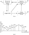
- FIG. 4 is an architectural diagram of controlling, by a legged robot system, a legged robot to move according to an embodiment of this application.
- the legged robot system includes a vision perception sub-system 401, a trajectory generating sub-system 402, and a movement control sub-system 403.
- the vision perception sub-system 401 obtains, based on state data of the legged robot, a termination position and a stepping sequence of the legged robot, and sends the obtained termination position and stepping sequence of the legged robot to the trajectory generating sub-system 402.
- the trajectory generating sub-system 402 receives the termination position and the stepping sequence of the legged robot sent by the vision perception sub-system 401, determines a trajectory of center of mass of the legged robot through the obtained state data of the legged robot, determines a joint torque of each joint of the legged robot based on the determined trajectory of center of mass of the legged robot, and sends the determined joint torque of the each joint of the legged robot to the movement control sub-system 403.
- the movement control sub-system 403 receives the determined joint torque of the each joint of the legged robot sent by the trajectory generating sub-system 402, controls, according to the determined joint torque of the each joint of the legged robot, the each joint to rotate, to drive the legged robot to move, and monitors the state data of the legged robot in real time in the process of controlling the legged robot to move, thereby ensuring that the legged robot can stably move.
- the foregoing embodiment involves the first relational data, the second relational data, and the third relational data, and based on the foregoing embodiment, the process of creating the foregoing three types of relational data is described in detail in the following embodiment:
- the stepping sequence indicates a stepping sequence of a plurality of legs of the legged robot, and performing a stepping action by any leg is referred to as a movement sub-process.
- an end position of the former movement sub-process is the same as an initiation position of the latter movement sub-process.
- first relational data is created for each movement sub-process.
- P init is a constant vector used for representing an initiation position of center of mass of the legged robot at the beginning of any movement period
- E t represents a duration vector
- C xk represents a component of the first constant C k corresponding to the k th movement sub-process on the x axis
- C yk represents a component of the first constant C k corresponding to the k th movement sub-process on the y axis
- C zk represents a component of the first constant C k corresponding to the
- a first constant C in the first relational data corresponding to movement of the legged robot from the initiation position to the termination position is formed by first constants C k corresponding to the plurality of movement sub-processes, that is, the first constant C in the first relational data corresponding to movement of the legged robot from the initiation position to the termination position includes components of a first constant C k corresponding to each movement sub-process on the x, y , and z axes.
- P init is a constant vector used for representing an initiation position of center of mass of the legged robot at the beginning of any movement period
- E t represents a duration vector
- C represents the first constant in the first relational data corresponding to movement of the legged robot from the initiation position to the termination position
- C 1 represents the first constant corresponding to the first movement sub-process
- C 2 represents the first constant corresponding to the second movement sub-process
- C k represents the first constant corresponding to the k th movement sub-process
- C n represents the first constant corresponding to the n th movement sub-process
- T
- movement of the legged robot from the initiation position to the termination position includes eight movement sub-processes, which are sequentially a movement sub-process 501, a movement sub-process 502, a movement sub-process 503, a movement sub-process 504, a movement sub-process 505, a movement sub-process 506, a movement sub-process 507, and a movement sub-process 508 according to a time sequence.
- the first 3 represents the quantity of components on the x, y , and z axes
- 7 represents that there are seven same positions in the eight movement sub-processes
- the second 3 represents that state data corresponding to each position includes such a total of 3 variables as a position of center of mass, a speed of center of mass, and an acceleration of center of mass.
- second-order derivation is performed on the first relational data of the k th movement sub-process with respect to the interval duration t , to obtain relational data between the acceleration of center of mass P ⁇ ( t ) of the k th movement sub-process and the interval duration t
- E a represents a time matrix, which is obtained by performing the second-order derivation on the duration vector E t with respect to the interval duration t
- E a ⁇ R 1 ⁇ 4 represents that the time matrix E a is a 4-dimensional row vector
- k is a positive integer not less than 1
- C xk represents a component of the first constant C k
- the relational data is stored in the form of a descriptive statement or a function.
- the dynamical equation used for representing the center of mass of the legged robot represents a relationship between movement of the legged robot and an external force to which the legged robot is subjected, and the external force to which the legged robot is subjected conforms to Newton's laws and Euler's equations.
- the gravity of the legged robot is equal to a sum of all external forces to which the legged robot is subjected, and a first-order derivative of an angular momentum of the legged robot with respect to a duration is equal to a torque to which the legged robot is subjected.
- the initiation position of center of mass P init is the same as the position of center of mass included in the state data of the legged robot in the initiation position.
- G is a constant matrix
- the constant matrix G ⁇ R 6 ⁇ 3 Y represents that the constant matrix G is a matrix of 6 rows and 3 Y columns, and represents a real number set in a multi-dimensional space
- f 0 ⁇ P ( t ) ⁇ is used for representing a sum of acting forces to which at least one leg in contact with the ground of the legged robot is subjected
- m represents the mass of the legged robot
- P t represents a change amount of the position of center of mass of the legged robot after
- P ⁇ t P ⁇ t P ⁇ t xy P ⁇ t xy + P ⁇ t xy P ⁇ t z + P ⁇ t z P ⁇ t xy + P ⁇ t z P ⁇ t z
- P t xy represents a component of change amount P t of the position of center of mass on a plane formed by the x and y axes, and the z coordinate corresponding to P t xy is 0;
- P t z represents a component of change amount P t of the position of center of mass on the z axis;
- the legged robot In a movement process of the legged robot, the legged robot has stable movement and a small change amount in the direction of the z axis, so that P ⁇ t z , P ⁇ t z , and P ⁇ t xy P ⁇ t z + P ⁇ t z P ⁇ t xy in the foregoing relations can be ignored; and P t xy , P ⁇ t xy , and P ⁇ t xy P ⁇ t xy all have small absolute values, and therefore can be ignored. Therefore, P ⁇ t P ⁇ t in the foregoing relational data between an acting force to which at least one leg of the legged robot is subjected and the position of center of mass P ( t ) of the legged robot can be ignored.
- the second relational data corresponding to the i th leg of the legged robot can be obtained, and the following relationship is met: ⁇ i P t ⁇ G i + H P t P ⁇ t + U i ⁇ G i + W g
- f i ⁇ P ( t ) ⁇ represents the acting force corresponding to the i th leg
- G i + is a constant matrix
- the constant matrix G i + represents a constant matrix corresponding to the i th leg
- H is a constant matrix
- P ( t ) represents a position of center of mass
- P ( t ) is a second-order derivative of a position of center of mass P ( t ) with respect to the interval duration t , and represents an acceleration of center of mass corresponding to the position of center of mass P( t )
- ⁇ represents a fourth constant corresponding to at least one leg of the legged robot
- U i represents a mapping matrix corresponding to the fourth constant ⁇ corresponding
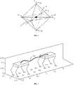
- a point is taken in each of positive and negative directions of the x , y , and z axes of a coordinate system, to obtain a point 1, a point 2, a point 3, a point 4, a point 5, and a point 6.
- the obtained six points are used as vertexes of a polyhedron, to obtain an offset ⁇ P j ′ of the position of center of mass of the legged robot.
- P new init P init + ⁇ P j ′
- P 0 new P 0 + ⁇ P j ′
- P 1 new P 1 + ⁇ P j ′ j is used for representing points obtained on the coordinate axes x , y , and z , which are 1, 2, 3, 4, 5, and 6;
- ⁇ represents an offset coefficient, and ⁇ is a constant;
- P j ′ is represented as an offset of the position of center of mass of the legged robot on a coordinate axis, and P j ′ corresponds to any one of the six points on the coordinate axes, optionally, coordinates of P j ′ are represented as ( ⁇ ⁇ x , 0, 0), (0, ⁇ y , 0), and (0, 0, ⁇ ⁇ z );
- P init is a constant vector used for representing an initiation position of center of mass of the legged robot at the beginning of any movement period;
- P 0 represents the position of center of mass of the legged robot in
- G is a constant matrix
- the constant matrix G ⁇ R 6 ⁇ 3 Y represents that the constant matrix G is a matrix of 6 rows and 3 Y columns, and represents a real number set in a multi-dimensional space
- f 0 ⁇ P ( t ) ⁇ is used for representing a sum of acting forces to which at least one leg in contact with the ground of the legged robot is subjected
- m represents the mass
- the third relational data is created based on a friction force constraint to which the legged robot is subjected, the fourth relational data, and the fifth relational data.
- the legged robot is subjected to a friction force constraint: a leg in contact with the ground of the legged robot is subjected to a friction force greater than 0, and the friction force to which the leg is subjected is not less than a component force of an acting force f i ⁇ P ( t ) ⁇ to which the leg in contact with the ground is subjected in a friction force direction, to avoid generating relative slide between the leg and the ground, thereby ensuring that the legged robot can normally move.
- An acting force f i ⁇ P ( t ) ⁇ corresponding to each of at least one leg of the legged robot is subjected to a friction force constraint, and the following relationship is met: ⁇ n i T ⁇ i P t ⁇ 0 t i 1 T ⁇ i P t 2 + t i 2 T ⁇ i P t 2 ⁇ ⁇ i n i T ⁇ i P t
- n i is a normal vector of a contact point in contact with the ground of the i th leg of the legged robot
- n i ⁇ R 3 ⁇ 1 represents that the normal vector n i is a 3-dimensional column vector, and represents a real number set in a multi-dimensional space
- t i 1 and t i 2 represent two tangent vectors on a plane perpendicular to the normal vector of the contact point in contact with the ground of the i th leg of the legged robot, the tangent vector t i
- a direction of the acting force to which the i th leg in contact with the ground of the legged robot is subjected is within a cone
- a contact point in contact with the ground of the i th leg is a vertex of the cone
- a connecting line within the cone from the vertex to any point of a base circle of the cone can be used as the direction of the acting force f i ⁇ P ( t ) ⁇ to which the i th leg in contact with the ground is subjected.
- the cone is approximately presented as a rectangular pyramid, and the acting force f i ⁇ P ( t ) ⁇ to which the i th leg in contact with the ground meets the following relation: ⁇ ⁇ i n i T ⁇ t i 1 T ⁇ ⁇ i n i T ⁇ t i 1 T ⁇ n i T n i T ⁇ i P t ⁇ 0 0 ⁇ ⁇ i min P t ⁇ i max P t
- ⁇ i is a friction coefficient
- n i is a normal vector of a contact point in contact with the ground of the i th leg of the legged robot
- n i ⁇ R 3 ⁇ 1 represents that the normal vector n i is a 3-dimensional column vector, and represents a real number set in a multi-dimensional space
- t i 1 and t i 2 represent two tangent vectors on a plane perpendicular to the normal vector
- variable matrix V is a column vector of 87 rows
- constant matrix H f is a matrix of 360 rows and 87 columns
- constant vector B f is a column vector of 360 rows
- constant vector D f is a column vector of 360 rows.
- J grf and J len in the third relational data includes a square of a variable matrix V, and the variable matrix V meets a friction force constraint.
- the minimum value of the target value J in the third relational data can be obtained. Therefore, a variable matrix V corresponding to the minimum value of the target value J can be obtained, that is, the second constant C free and the fourth constant ⁇ corresponding to the minimum value of the target value J are obtained, the first constant C whose value is determined is obtained through the second constant C free and the third constant h whose values are determined, and by substituting the first constant C whose value is determined into the first relational data, a trajectory of center of mass of the legged robot is obtained.
- a parameter slightly affecting the position of center of mass of the legged robot is ignored, and constraints of positions of center of mass, speeds, and accelerations in the initiation position and the termination position on the position of center of mass, and a friction force constraint to which the legged robot in contact with the ground is subjected are considered; determining the position of center of mass is converted in to a quadratic programming problem, to solve a trajectory of center of mass with high stability; and subsequently, with reference to the termination position of the foothold of the legged robot, a joint torque of each joint of the legged robot is obtained based on inverse kinematics, and the plurality of joints are controlled according to joint torques of the plurality of joints to rotate, to drive the legged robot to move.
- the method for determining the position of center of mass is applicable to various legged robots, for example, a two-legged robot, a four-legged robot or a multi-legged robot; is applicable to various gaits of the legged robot, for example, two-legged walking, four-legged walking, four-legged jogging or a random gait; is applicable to various complex environments, for example, a flat ground, an uneven ground, a slope, or stairs; can use any order of the interval duration t , and can use any movement process in the process from the initiation position to the termination position; and can keep, in a case that the ground is a plane or has a relatively small height difference, the height of the center of mass of the robot unchanged, and use only 2 groups of curves to plan movement of the center of mass in the plane.
- Constraints of the state data in the initiation position and the state data in the termination position on the position of center of mass may be determined according to actual requirements, and it is necessary to ensure that a curve parameter having a constraint added still has an independent variable.
- sampling time points When sampling time points are selected, sampling can be performed in any position on the trajectory of the position of center of mass, and a larger quantity of sampling time points indicates more proper distribution, and a more reliable movement trajectory of center of mass obtained, but a larger dimension and a longer solving time of the quadratic programming problem.
- a distance corresponding to a sampling time point in the third relational data can be determined through a plurality of sampling time points, and the distance can include components in three directions of the x axis, the y axis, and the z axis, for which different weights can be selected according to an actual situation; and in addition to the acting force of the ground and the curve oscillation amplitude, a sum of squares of accelerations, a sum of squares of speed differences between neighboring points, a sum of squares of differences between accelerations, and the like can be further considered.
- Simplification of a cone of friction can be performed by using an inscribed pyramid with N (N>4) sloping sides of the cone of friction, and a larger value of N indicates more accurate approximation to the cone of friction, but a larger dimension and a longer solving time of the quadratic programming problem.
- Position of a contact point the contact point is not merely limited to a contact point in contact with the ground on a leg of the legged robot, and is similarly applicable to a case that a part of the robot such as the body, the trunk, or the upper limb is in contact with an environment.
- Polyhedron whose position of center of mass has a non-deterministic constraint: any polyhedron meeting an actual requirement may be used, and an increase in the quantity of vertexes of the polyhedron causes increases in the dimension and the solving time of the quadratic programming problem.
- a polyhedron In a case that a position of center of mass in a single direction is determined and has a change that can be ignored, a polyhedron can be dimensionally reduced to a parallel polygon.
- positions of center of mass in two directions are determined and have changes that can be ignored, a polyhedron can be dimensionally reduced to a straight line.
- positions of center of mass in all three directions are determined and have changes that can be ignored, a polyhedron can be dimensionally reduced to a point.
- a legged robot is configured with 4 legs, and the legged robot moves from an initiation position to a termination position according to a determined trajectory of center of mass 701.
- a legged robot generates a trajectory of position of center of mass once in each half stepping period, and curve graphs of changes in a position of center of mass, a speed of center of mass, and an acceleration of center of mass of the legged robot with an interval duration are shown.
- Two curves in each curve graph respectively represent position of center of mass curves in which the highest powers of the interval duration t included in the position of center of mass P ( t ) are respectively 3 and 6.
- the legged robot is configured with 4 legs, which are respectively a right rear leg, a right front leg, a left rear leg, and a left front leg, and a stepping sequence of the legged robot is stepping with the right rear leg, stepping with the right front leg, stepping with the left rear leg, and stepping with the left front leg.
- each half stepping period is stepping with the right rear leg and stepping with the right front leg, or stepping with the left rear leg and stepping with the left front leg.
- the legged robot repeatedly performs the stepping process of the plurality of legs according to the stepping sequence, thereby enabling the legged robot to move. It can be known from FIG. 8 that, a deviation between the position of center of mass curves in which the highest powers of the interval duration t included in the position of center of mass P ( t ) of the legged robot are respectively 3 and 6 is small, and therefore, it is determined that the highest power of the interval duration t included in the position of center of mass P ( t ) can be any value.
- a legged robot generates a trajectory of the position of center of mass once in each stepping period, and curve graphs of changes in a position of center of mass, a speed of center of mass, and an acceleration of center of mass of the legged robot with an interval duration are shown.
- Two curves in each curve graph respectively represent position of center of mass curves in which the highest powers of the interval duration t included in the position of center of mass P ( t ) are respectively 3 and 6.
- the legged robot is configured with 4 legs, which are respectively a right rear leg, a right front leg, a left rear leg, and a left front leg, and a stepping sequence of the legged robot is stepping with the right rear leg, stepping with the right front leg, stepping with the left rear leg, and stepping with the left front leg.
- each stepping period is stepping with the right rear leg, stepping with the right front leg, stepping with the left rear leg, and stepping with the left front leg.
- the legged robot repeatedly performs the stepping process of the plurality of legs according to the stepping sequence, thereby enabling the legged robot to move. It can be known from FIG. 9 that, a deviation between the position of center of mass curves in which the highest powers of the interval duration t included in the position of center of mass P ( t ) of the legged robot are respectively 3 and 6 is small, and therefore, it is determined that the highest power of the interval duration t included in the position of center of mass P ( t ) can be any value.
- the first row of images represents curves indicating that the legged robot generates a trajectory of the position of center of mass once in each half stepping period, and a total torque and an omitted torque of the legged robot change with the interval duration.
- Three curve graphs in the first row in FIG. 10 represents curves of changes in component torques of the total torque and the omitted torque of the legged robot on the coordinate axes x, y, and z with the interval duration when the legged robot generates a trajectory of the position of center of mass once in each half stepping period.
- the second row of images represents curves indicating that the legged robot generates a trajectory of the position of center of mass once in each stepping period, and a total torque and an omitted torque of the legged robot change with the interval duration.
- Three curve graphs in the second row in FIG. 10 represents curves of changes in component torques of the total torque and the omitted torque of the legged robot on the coordinate axes x, y, and z with the interval duration when the legged robot generates a trajectory of the position of center of mass once in each stepping period. It can be known from FIG. 10 that, the torque omitted when the position of center of mass is determined in the foregoing embodiment is close to 0, indicating that the torque can be ignored.
- FIG. 11 shows curves of changes of the position of center of mass determined by the legged robot for the legged robot according to the method for determining the position of center of mass in the foregoing embodiment and the position of center of mass of the legged robot with the interval duration.
- the first row of images represents curves of changes in the position of center of mass with the interval duration when the legged robot slowly moves
- the second row of images represents curves of changes in the position of center of mass with the interval duration when the legged robot quickly moves. It can be known from FIG.
- FIG. 12 is a flowchart of a method for determining a position of center of mass according to an embodiment of this application, applicable to a legged robot. As shown in FIG. 12 , the method includes the following steps.
- the second state data includes at least a target position of center of mass.
- the target position of center of mass is represented in the form of coordinates in a coordinate system or in the form of a vector.
- the target position of center of mass of the legged robot is [20, 35, 80].
- the second state data includes a target position of center of mass
- step 1201 includes: obtaining, in a case that the legged robot is in the termination position, a position of a contact point in contact with the ground of the at least one leg configured for the legged robot; and determining the target position of center of mass based on the position of the contact point of the at least one leg.
- the legged robot is a four-legged robot.
- the legged robot moves to the termination position, four legs of the four-legged robot are all in contact with the ground. Therefore, four contact positions in contact with the ground on the four legs are obtained, and based on the four contact positions, the target position of center of mass of the legged robot in the termination position is determined.
- the center of mass is the center of mass of the legged robot, and the position of center of mass is a position of the center of mass of the legged robot.
- the target position of center of mass is a position of the center of mass of the legged robot intended when the legged robot moves to the termination position.
- the termination position is a position to be reached by the legged robot. In this case, the legged robot has not reached the termination position.
- the termination position is determined by the legged robot based on an environment in which the legged robot is located.
- the legged robot obtains, through a vision perception system, an image including an environment in a movement direction of the legged robot, performs feature extraction on the image including the environment, determines the termination position of the legged robot, determines the second state data for the termination position, and determines, a position of a contact point in contact with the ground on the at least one leg when the legged robot is in the termination position.
- the vision perception system includes a camera, and the legged robot photographs the environment in the movement direction of the legged robot through the camera, to obtain the image including the environment in the movement direction of the legged robot.
- a center position of the plurality of contact positions is determined; and based on the height of the legged robot and the center position, the target position of center of mass is determined.
- a coordinate system with a right-h and rule is used, a movement direction of the legged robot is used as the X axis, a direction on the left side of the legged robot and perpendicular to the X axis is used as the Y axis, and a direction perpendicular to the ground is used as the Z axis; and through contact positions on a plurality of legs of the legged robot, a center position of the plurality of contact positions is determined, and a coordinate value of the center position on the Z axis is added to the height value of the legged robot, to obtain a coordinate value of the target position of center of mass in the world coordinate system, that is, the target position of center of mass is determined.
- the second state data further includes a target speed of center of mass
- step 1201 further includes: obtaining first state data of the legged robot in an initiation position, where the first state data includes at least an initiation position of center of mass; and determining a ratio of a distance between the target position of center of mass and the initiation position of center of mass to the target movement duration as the target speed of center of mass.
- the initiation position is a current position of the legged robot, and the initiation position of center of mass is a current position of the center of mass of the legged robot.
- a speed of center of mass is a movement speed of the center of mass of the legged robot, and the speed of center of mass can be represented with a vector.
- the target speed of center of mass is a movement speed of the center of mass of the legged robot intended when the legged robot moves to the termination position.
- the distance between the target position of center of mass and the initiation position of center of mass represents a movement distance of the center of mass of the legged robot in the process that the legged robot moves from the initiation position to the termination position.
- the target movement duration indicates a duration required for the legged robot to move from the initiation position to the termination position.
- the target movement duration is any duration, for example, 2 seconds or 3 seconds.
- a speed at which the legged robot moves from the initiation position to the termination position that is, a target speed of center of mass at which the legged robot moves to the termination position can be determined.
- the target speed of center of mass is represented in the form of a vector.
- a position of center of mass of the legged robot is represented in the form of a vector, for example, [1, 2, 3], and all elements in the vector respectively represent coordinate values of the center of mass of the legged robot on the x axis, the y axis, and the z axis of the coordinate system. Therefore, the distance between the target position of center of mass and the initiation position of center of mass is also represented with a vector, representing displacements of the center of mass of the legged robot on the x axis, the y axis, and the z axis, and a ratio of the distance to the target movement duration is component speeds of the target speed of center of mass on the x axis, the y axis, and the z axis.
- the second state data further includes a target acceleration of center of mass
- the first state data further includes an initiation speed of center of mass
- step 1201 further includes: determining a ratio of a difference between the target speed of center of mass and the initiation speed of center of mass to the target movement duration as the target acceleration.
- the target acceleration of center of mass is an acceleration of the center of mass of the legged robot intended when the legged robot moves to the termination position.
- the target acceleration of center of mass is represented in the form of a vector.
- the initiation speed of center of mass indicates a speed of the center of mass of the legged robot when the legged robot is in the initiation position.
- the initiation speed of center of mass is represented in the form of a vector.
- a difference between the target speed of center of mass and the initiation speed of center of mass indicates a speed of center of mass change amount of the legged robot when the legged robot moves from the initiation position to the termination position, and a ratio of the change amount of the speed of center of mass to the target movement duration is a change amount of the speed of center of mass per unit time of the legged robot when the legged robot moves from the initiation position to the termination position, that is, the target acceleration of center of mass of the legged robot at the time of moving to the termination position.
- the second state data includes at least a target position of center of mass, a target speed of center of mass, and a target acceleration of center of mass
- step 1201 includes: obtaining, in a case that the legged robot is in the termination position, a position of a contact point in contact with the ground of the at least one leg configured for the legged robot; and determining the target position of center of mass based on the position of the contact point of the at least one leg; obtaining first state data of the legged robot in an initiation position, where the first state data includes at least an initiation position of center of mass, and determining a ratio of a distance between the target position of center of mass and the initiation position of center of mass to the target movement duration as the target speed of center of mass; and determining a ratio of a difference between the target speed of center of mass and the initiation speed of center of mass to the target movement duration as the target acceleration.
- first relational data the first relational data indicating a relationship between an interval duration t and a position of center of mass P ( t ) of the legged robot.
- the interval duration t indicates a duration of an interval between any time point in a process that the legged robot moves from an initiation position to a termination position and a start time point corresponding to the initiation position.
- the position of center of mass P ( t ) indicates a position of center of mass of the legged robot within the interval duration t .
- the first relational data includes a first constant C whose value is not determined, and the first constant C is used for representing a relationship between the position of center of mass P ( t ) and the interval duration t .
- the first constant C is represented in the form of a vector or a matrix.
- the first relational data is stored in the form of a descriptive statement or a function.
- step 1202 includes: the first relational data is set as follows: the position of center of mass P ( t ) is a product of the first constant C and a duration matrix E .
- the duration matrix E is a matrix used for representing the interval duration t .
- the position of center of mass of the legged robot changes with a moving interval duration t in a movement process of the legged robot
- the position of center of mass after any interval duration t has a corresponding change amount of position of center of mass
- a sum of the change amount of the position of center of mass corresponding to the interval duration t and the initiation position of center of mass of the legged robot at the beginning of movement is used as the corresponding position of center of mass P ( t ) of the legged robot after any interval duration t , thereby determining the first relational data indicating a relationship between the position of center of mass P ( t ) and the interval duration t , and subsequently determining the trajectory of center of mass of the legged robot through the first relational data.
- the first relational data is used for representing a position of center of mass at any time point in the process that the legged robot moves from the initiation position to the termination position, and the target movement duration indicates a duration required for the legged robot to move from the initiation position to the termination position. Therefore, through the target movement duration and the first relational data, the prediction position of center of mass of the legged robot when the legged robot moves to the termination position according to the trajectory of center of mass indicated by the first relational data can be predicted. Because the first relational data includes the first constant C whose value is not determined, the obtained prediction position of center of mass is related to the first constant C whose value is not determined.
- the prediction state data includes a prediction position of center of mass
- step 1203 includes: determining, based on the first relational data, the prediction position of center of mass of the legged robot after the target movement duration elapses from an initiation position.
- the first relational data indicates a relationship between the interval duration t and the position of center of mass P ( t ) of the legged robot, and the first relational data includes the first constant C whose value is not determined. Therefore, the target movement duration is used as the interval duration t and substituted into the first relational data, to obtain the prediction position of center of mass of the legged robot, and the prediction position of center of mass is related to the first constant C whose value is not determined.
- the prediction state data includes a prediction speed of center of mass
- step 1203 includes: creating, based on the first relational data, relational data between the interval duration t and a speed of center of mass of the legged robot; and determining, based on the relational data between the interval duration t and the speed of center of mass of the legged robot, the prediction speed of center of mass of the legged robot after the target movement duration elapses from an initiation position.
- the prediction speed of center of mass is a speed of center of mass of the legged robot predicted through the first relational data when the legged robot moves to the termination position, and the prediction speed of center of mass is related to the first constant C whose value is not determined.
- the first-order derivative of the first relational data with respect to the interval duration t is obtained, to obtain relational data between the interval duration t and the speed of center of mass of the legged robot, and the target movement duration is substituted into the relational data, to obtain the prediction speed of center of mass.
- the prediction state data includes a prediction acceleration of center of mass
- step 1203 includes: creating, based on the first relational data, relational data between the interval duration t and an acceleration of center of mass of the legged robot; and determining, based on the relational data between the interval duration t and the acceleration of center of mass of the legged robot, the prediction acceleration of center of mass of the legged robot after the target movement duration elapses from an initiation position.
- the prediction acceleration of center of mass is an acceleration of center of mass of the legged robot predicted through the first relational data when the legged robot moves to the termination position, and the prediction acceleration of center of mass is related to the first constant C whose value is not determined.
- the second-order derivative of the first relational data with respect to the interval duration t is obtained, to obtain relational data between the interval duration t and the acceleration of center of mass of the legged robot, and the target movement duration is substituted into the relational data, to obtain the prediction acceleration of center of mass.
- the prediction state data includes at least a prediction position of center of mass, a prediction speed of center of mass, and a prediction acceleration of center of mass
- step 1203 includes: determining, based on the first relational data, the prediction position of center of mass of the legged robot after the target movement duration elapses from an initiation position; creating, based on the first relational data, relational data between the interval duration t and a speed of center of mass of the legged robot; and determining, based on the relational data between the interval duration t and the speed of center of mass of the legged robot, the prediction speed of center of mass of the legged robot after the target movement duration elapses from an initiation position; and creating, based on the first relational data, relational data between the interval duration t and an acceleration of center of mass of the legged robot; and determining, based on the relational data between the interval duration t and the acceleration of center of mass of the legged robot, the prediction acceleration of center of mass of the legged robot after
- the second relational data corresponding to the at least one leg separately indicating a relationship between an acting force f i corresponding to the at least one leg and the position of center of mass P ( t ) .
- the acting force f i indicates an acting force to which the i th leg in contact with the ground of the legged robot is subjected, and i is a positive integer.
- the second relational data includes the first constant C whose value is not determined. in the legged robot, the second relational data is stored in the form of a descriptive statement or a function.
- step 1204 includes: creating sixth relational data, creating seventh relational data, and creating, based on the sixth relational data and the seventh relational data, the second relational data corresponding to the at least one leg.
- the sixth relational data indicates a relationship between an angular momentum L of the legged robot and the interval duration t , and the angular momentum L is used for representing a change in a gesture of the legged robot.
- the seventh relational data indicates a positive correlation between the acting force f i (L) corresponding to the at least one leg and the angular momentum L .
- the seventh relational data is used for representing an effect of the gesture of the legged robot on the acting force corresponding to the at least one leg of the legged robot.
- the sixth relational data and the seventh relational data are stored in the form of descriptive statements or functions.
- the third relational data indicates a positive correlation between the target value J and the state data error and a square of an acting force f i to which the at least one leg in contact with the ground is subjected. Because the prediction position of center of mass is related to the first constant C , the state data error is also related to the first constant C . Therefore, the target value J is related to the first constant C , that is, the third relational data includes the first constant C whose value is not determined. in the legged robot, the third relational data is stored in the form of a descriptive statement or a function.
- a square of a product of each acting force f i and a corresponding weight is determined, and a sum of squares corresponding to an acting force f i corresponding to at least one leg is used as a weighted sum of squares of the acting force f i corresponding to the at least one leg.
- a weight corresponding to each acting force f i is arbitrarily set by the legged robot.
- a weighted sum of squares of the acting force f i corresponding to the at least one leg in contact with the ground of the legged robot is equal to a sum of weighted squares F i corresponding to the at least one leg.
- the second state data includes a target position of center of mass
- the prediction state data includes a prediction position of center of mass
- step 1205 includes: determining a first difference between the target position of center of mass and the prediction position of center of mass; and setting the target value J to a sum value of a weighted sum of squares of the acting force f i corresponding to the at least one leg, and a square of the first difference.
- the first difference is used for indicating a difference between the target position of center of mass and the prediction position of center of mass when the legged robot is in the termination position. Because the prediction position of center of mass is related to the first constant C , the first difference is related to the first constant C , and after the target value J is set to the sum value of the weighted sum of squares of the acting force f i corresponding to the at least one leg, and the square of the first difference, the target value J is related to a quadratic term of the first constant C .
- quadratic terms of the first constant C include quadratic constant terms formed by the plurality of constant terms, that is, a square of each constant term or a product of any two constant terms.
- the first constant C includes constant terms C x , C y , and C z , and therefore the quadratic terms of the first constant C include quadratic constant terms such as C x 2 , C y 2 , C z 2 , C x C y , C x C z , and C y C z .
- a distance between the target position of center of mass and the prediction position of center of mass is determined as the first difference.
- each of the target position of center of mass and the prediction position of center of mass is represented in the form of coordinates, and therefore the first difference is also represented in the form of coordinates.
- the target position of center of mass includes first coordinate values on the x, y , and z axes
- the prediction position of center of mass includes second coordinate values on the x, y, and z axes
- differences between the first coordinate values and the second coordinate values on the x, y , and z axes are determined, to obtain the first difference.
- the first difference includes differences on the x, y, and z axes, and a weighted sum of squares of the differences of the first difference on the x, y , and z axes is used as a square of the first difference.
- weights corresponding to the x, y , and z axes are arbitrarily set by the legged robot.
- the second state data includes a target speed of center of mass
- the prediction state data includes a prediction speed of center of mass
- step 1205 includes: determining a third difference between the target speed of center of mass and the prediction speed of center of mass; and setting the target value J to a sum value of a weighted sum of squares of the acting force f i corresponding to the at least one leg, and a square of the third difference.
- the third difference is used for indicating a difference between the target speed of center of mass of the legged robot and the prediction speed of center of mass when the legged robot is in the termination position. Because the prediction speed of center of mass is related to the first constant C , the third difference is related to the first constant C , and after the target value J is set to the sum value of the weighted sum of squares of the acting force f i corresponding to the at least one leg, and the square of the third difference, the target value J is related to a quadratic term of the first constant C .
- quadratic terms of the first constant C include quadratic constant terms formed by the plurality of constant terms, that is, a square of each constant term or a product of any two constant terms.
- the first constant C includes constant terms C x, C y , and C z , and therefore the quadratic terms of the first constant C include quadratic constant terms such as C x 2 , C y 2 , C z 2 , C x C y , C x C z , and C y C z .
- each of the target speed of center of mass and the prediction speed of center of mass is represented in the form of coordinates, and therefore the third difference is also represented in the form of coordinates.
- the target speed of center of mass includes first component speeds on the x, y , and z axes
- the prediction speed of center of mass includes second component speeds on the x, y , and z axes
- speed differences between the first component speeds and the second component speeds on the x, y, and z axes are determined, to obtain the third difference.
- the third difference includes speed differences on the x, y , and z axes, and a weighted sum of squares of the speed differences of the third difference on the x, y, and z axes is used as a weighted square of the third difference.
- x, y , and z axes are arbitrarily set by the legged robot.
- the second state data includes a target acceleration of center of mass
- the prediction state data includes a prediction acceleration of center of mass
- step 1205 includes: determining a second difference between the target acceleration of center of mass and the prediction acceleration of center of mass; and setting the target value J to a sum value of a weighted sum of squares of the acting force f i corresponding to the at least one leg, and a square of the second difference.
- the second difference is used for indicating a difference between the target acceleration of center of mass of the legged robot and the prediction acceleration of center of mass when the legged robot is in the termination position. Because the prediction acceleration of center of mass is related to the first constant C , the second difference is related to the first constant C , and after the target value J is set to the sum value of the weighted sum of squares of the acting force f i corresponding to the at least one leg, and the square of the third difference, the target value J is related to a quadratic term of the first constant C .
- quadratic terms of the first constant C include quadratic constant terms formed by the plurality of constant terms, that is, a square of each constant term or a product of any two constant terms.
- the first constant C includes constant terms C x , C y , and C z , and therefore the quadratic terms of the first constant C include quadratic constant terms such as C x 2 , C y 2 , C z 2 , C x C y , C x C z , and C y C z .
- each of the target acceleration of center of mass and the prediction acceleration of center of mass is represented in the form of coordinates, and therefore the second difference is also represented in the form of coordinates.
- the target acceleration of center of mass includes first component accelerations on the x, y , and z axes
- the prediction acceleration of center of mass includes second component accelerations on the x, y , and z axes
- acceleration differences between the first component accelerations and the second component accelerations on the x, y, and z axes are determined, to obtain the second difference.
- the second difference includes acceleration differences on the x, y, and z axes, and a weighted sum of squares of the acceleration differences of the second difference on the x, y , and z axes is used as a weighted square of the second difference.
- x, y , and z axes are arbitrarily set by the legged robot.
- step 1205 The three possible implementations of the foregoing step 1205 are respectively described only by using state data including positions of center of mass, speeds of center of mass, or accelerations of center of mass. Additionally, any two of the foregoing three possible implementations can be combined, or the three possible implementations are combined.
- the target value J is set to a sum value of a weighted sum of squares of the acting force f i corresponding to the at least one leg and a weighted sum of squares of the first difference and the second difference; or if the state data error includes the first difference and the third difference, the target value J is set to a sum value of a weighted sum of squares of the acting force f i corresponding to the at least one leg and a weighted sum of squares of the first difference and the third difference; or if the state data error includes the second difference and the third difference, the target value J is set to a sum value of a weighted sum of squares of the acting force f i corresponding to the at least one leg and a weighted sum of squares of the second difference and the third difference. Weights of any two differences included in the state data error are arbitrarily set by the legged robot.
- the state data error includes the first difference, the second difference, and the third difference
- the target value J is set to a sum value of a weighted sum of squares of the acting force f i corresponding to the at least one leg and a weighted sum of squares of the first difference, the second difference, and the third difference.
- weights of the first difference, the second difference, and the third difference are arbitrarily set by the legged robot.
- a sum of the weighted square of the first difference, the weighted square of the second difference, and the weighted square of the third difference is used as a weighted sum of squares of the first difference, the second difference, and the third difference.
- step 1205 includes the following steps 12051 to 12053:
- a sampling time point refers to a time point between a start time point corresponding to the initiation position and a target time point corresponding to the termination position.
- the plurality of sampling time points include two or more sampling time points. Interval durations between any two neighboring sampling time points may be equal or not equal.
- the movement duration is 60 seconds
- the start time point corresponding to the initiation position is the 0 th second
- the target time point corresponding to the termination position is the 60 th second
- 5 sampling time points are selected within the movement duration.
- the first sampling time point is the 10 th second
- the second sampling time point is the 20 th second
- the third sampling time point is the 120 th second
- the fourth sampling time point is the 40 th second
- the fifth sampling time point is the 50 th second
- the first sampling time point is the 5 th second
- the second sampling time point is the 20 th second
- the third sampling time point is the 25 th second
- the fourth sampling time point is the 40 th second
- the fifth sampling time point is the 55 th second.
- step 12051 includes: the movement duration is divided in to a plurality of time periods, and an end time point of each time period is used as a sampling time point.
- the obtained plurality of time periods may be equal or not equal.
- the fourth relational data indicates a relationship between the first constant C and a sampling position of center of mass Q ( C ) , and the sampling position of center of mass Q ( C ) indicates a position of center of mass of the legged robot at the corresponding sampling time point.
- the fourth relational data is stored in the form of a descriptive statement or a function.
- the first relational data indicates that the position of center of mass P ( t ) is a product of the first constant C and the duration matrix E . Therefore, by substituting an interval duration between any sampling time point and the start time point into the duration matrix E in the first relational data, the value of the duration matrix E at the any sampling time point is determined, to obtain the fourth relational data corresponding to the sampling time point, where the fourth relational data indicates a relationship between the first constant C and the sampling position of center of mass Q ( C ) .
- the value of the first constant C included in the fourth relational data is not determined, but values of other first constants included in the fourth relational data have all been determined.
- the third relational data indicates a positive correlation between the target value J and a square of the acting force f i corresponding to the at least one leg corresponding to the each sampling time point, the state data error, and the sampling position of center of mass Q ( C ) .
- the second state data includes a target position of center of mass
- the prediction state data includes a prediction position of center of mass
- step 12053 includes: determining a first difference between the target position of center of mass and the prediction position of center of mass; and setting the target value J to a sum value of a first value, a second value, and a third value.
- the first value is a square of the first difference
- the second value is a weighted sum of squares of a plurality of distances.
- the plurality of distances include a distance between any two neighboring positions of center of mass of an initiation position of center of mass in an initiation position, a plurality of sampling positions of center of mass, and the prediction position of center of mass
- the third value is a weighted sum of squares of the acting force f i corresponding to the at least one leg corresponding to the each sampling time point.
- a weight of each distance is arbitrarily set by the legged robot.
- a squared value of a product of each distance and a corresponding weight is determined, and a sum of squared values corresponding to a plurality of distances is used as a weighted sum of squares of the plurality of distances.
- the weighted sum of squares of the plurality of distances can reflect the length of the trajectory of center of mass, and can reduce the oscillation amplitude of the trajectory of center of mass curve.
- the first difference and the plurality of distances are all related to the first constant C .
- the first value is the square of the first difference
- the second value is the weighted sum of squares of the plurality of distances. Therefore, the first value and the second value are both related to the quadratic terms of the first constant C , and after the target value J is set to the sum value of the first value, the second value, and the third value, the target value J is related to the quadratic terms of the first constant C .
- quadratic terms of the first constant C include quadratic first constant terms formed by the plurality of first constant terms, that is, a square of each first constant term or a product of any two first constant terms.
- the first constant C includes first constant terms (C x , C y , and C z , and therefore the quadratic terms of the first constant C include quadratic first constant terms such as C x 2 , C y 2 , C z 2 , C x C y , C x C z , and C y C z .
- the second state data includes a target speed of center of mass
- the prediction state data includes a prediction speed of center of mass
- step 12053 includes: determining a third difference between the target speed of center of mass and the prediction speed of center of mass; and setting the target value J to a sum value of a second value, a third value, and a fifth value.
- the fifth value is a square of the third difference
- the second value is a weighted sum of squares of a plurality of distances.
- the third value is a weighted sum of squares of the acting force f i corresponding to the at least one leg corresponding to the each sampling time point.
- the third difference and the plurality of distances are all related to the first constant C .
- the fifth value is the square of the third difference
- the second value is the weighted sum of squares of the plurality of distances. Therefore, the fifth value and the second value are both related to the quadratic terms of the first constant C , and after the target value J is set to the sum value of the second value, the third value, and the fifth value, the target value J is related to the quadratic terms of the first constant C .
- quadratic terms of the first constant C include quadratic first constant terms formed by the plurality of first constant terms, that is, a square of each first constant term or a product of any two first constant terms.
- the first constant C includes first constant terms C x , C y , and C z , and therefore the quadratic terms of the first constant C include quadratic first constant terms such as C x 2 , C y 2 , C z 2 , C x C y , C x C z , and C y C z .
- the second state data includes a target acceleration of center of mass
- the prediction state data includes a prediction acceleration of center of mass
- step 12053 includes: determining a second difference between the target acceleration of center of mass and the prediction acceleration of center of mass; and setting the target value J to a sum value of a second value, a third value, and a fourth value.
- the fourth value is a square of the second difference, and the second value is a weighted sum of squares of a plurality of distances.
- the third value is a weighted sum of squares of the acting force f i corresponding to the at least one leg corresponding to the each sampling time point.
- the fourth value is the square of the second difference, and the second value is the weighted sum of squares of the plurality of distances. Therefore, the fourth value and the second value are both related to the quadratic terms of the first constant C , and after the target value J is set to the sum value of the second value, the third value, and the fourth value, the target value J is related to the quadratic terms of the first constant C .
- quadratic terms of the first constant C include quadratic first constant terms formed by the plurality of first constant terms, that is, a square of each first constant term or a product of any two first constant terms.
- the first constant C includes first constant terms C x , C y , and C z , and therefore the quadratic terms of the first constant C include quadratic first constant terms such as C x 2 , C y 2 , C z 2 , C x C y , C x C z , and C y C z .
- step 12053 The three possible implementations of the foregoing step 12053 are respectively described only by using state data including positions of center of mass, speeds of center of mass, or accelerations of center of mass. Additionally, any two of the foregoing three possible implementations can be combined, or the three possible implementations are combined.
- the target value J is set to a sum value of a weighted sum of squares of the first difference and the second difference, the second value, and the third value; or if the state data error includes the first difference and the third difference, the target value J is set to a sum value of a weighted sum of squares of the first difference and the third difference, the second value, and the third value; or if the state data error includes the second difference and the third difference, the target value J is set to a sum value of a weighted sum of squares of the second difference and the third difference, the second value, and the third value. Weights of any two differences included in the state data error are arbitrarily set by the legged robot.
- the state data error includes the first difference, the second difference, and the third difference
- the target value J is set to a sum value of a weighted sum of squares of the first difference, the second difference, and the third difference, the second value, and the third value.
- weights of the first difference, the third difference, and the second difference are arbitrarily set by the legged robot.
- a squared value of a product of the first difference and the corresponding weight, a squared value of a product of the third difference and the corresponding weight, and a squared value of a product of the second difference and the corresponding weight are determined, and a sum of the squared value corresponding to the first difference, the squared value corresponding to the third difference, and the squared value corresponding to the second difference is a weighted sum of squares of the first difference, the third difference, and the second difference.
- the eighth relational data indicates a relationship between an initiation position of center of mass of the legged robot in an initiation position and the first constant C
- the ninth relational data indicates a relationship between an initiation speed of center of mass of the legged robot in the initiation position and the first constant C
- the tenth relational data indicates a relationship between an initiation acceleration of center of mass of the legged robot in the initiation position and the first constant C .
- the eighth relational data, the ninth relational data, and the tenth relational data are stored in the form of descriptive statements or functions.
- step 1206 includes: substituting the start time point into the first relational data, to obtain the eighth relational data; obtaining a first-order derivative of the first relational data with respect to the interval duration t , and substituting the start time point into relational data of the obtained first-order derivative, to obtain the ninth relational data; and obtaining a second-order derivative of the first relational data with respect to the interval duration t , and substituting the start time point into relational data of the obtained second-order derivative, to obtain the tenth relational data.
- the value of the first constant C at which the target value J has the minimum value is determined, so that the first state data of the legged robot in the initiation position meets the first relational data corresponding to the first constant C whose value is determined, and the acting force corresponding to the at least one leg in the initiation position meets the second relational data, to ensure accuracy of the determined value of the first constant C .
- a friction force constraint condition is created, the friction force constraint condition indicates a friction force constraint condition met by the acting force to which the at least one leg in contact with the ground of the legged robot is subjected, and the friction force constraint condition includes the first constant C whose value is not determined.
- the friction force constraint condition is met, the value of the first constant C at which the target value J has the minimum value is determined based on the eighth relational data, the ninth relational data, the tenth relational data, the second relational data, and the third relational data.
- the first relational data indicates a relationship between the position of center of mass P ( t 0 ) and the interval duration t ; and except the interval duration t , the first relational data does not include other first constants whose values are not determined. Therefore, the first relational data corresponding to the first constant C whose value is determined can represent a trajectory of center of mass of the legged robot.
- step 3 is similar to step 311. Details are not described herein again.
- step 312. This step is similar to step 312. Details are not described herein again.
- step 3 is similar to step 313. Details are not described herein again.
- a movement process that the legged robot moves from the initiation position to the termination position is describes; and in another embodiment, after reaching the termination position, the legged robot can further continue to perform the latter movement process, to perform the foregoing steps 1201 to 1211 by using the termination position of the former movement process as the initiation position of the latter movement process, so that the legged robot moves to the termination position of the latter process, thereby implementing a plurality of consecutive movement processes of the legged robot.
- the termination position of the last movement process is used as a target position of the legged robot, and after it is determined that the legged robot moves to the termination position of the current movement process, it is detected whether the termination position coincides with the target position. In response to that the termination position does not coincide with the target position, the first state data is determined for the termination position. In response to that the termination position coincides with the target position, the second state data is determined for the termination position.
- the legged robot as an execution body; and in another embodiment, the foregoing steps 1201 to 1211 are performed by a server, the server determines, based on the position of center of mass P ( t 0 ) and the termination position, the joint torques of the plurality of joints of the legged robot, and sends a movement instruction to the legged robot, where the movement instruction carries the joint torques of the plurality of joints, and the legged robot controls, according to the joint torques of the plurality of joints, the plurality of joints to rotate, to drive the legged robot to move.
- the server determines, based on the position of center of mass P ( t 0 ) and the termination position, the joint torques of the plurality of joints of the legged robot, and sends a movement instruction to the legged robot, where the movement instruction carries the joint torques of the plurality of joints, and the legged robot controls, according to the joint torques of the plurality of joints, the plurality of joints to rotate, to drive the legged robot to move.
- the server establishes communicative connection to the plurality of joints of the legged robot, the server sends a rotating instruction to the plurality of joints of the legged robot according to the determined joint torques of the plurality of joints, where the rotating instruction carries the joint torques of the corresponding joints, and after receiving the rotating instruction, the plurality of joints of the legged robot rotate according to the corresponding joint torques, to drive the legged robot to move.
- the legged robot as an execution body; and in another embodiment, the foregoing steps 1201 to 1208 are performed by the server.
- the server After obtaining the first relational data corresponding to the first constant C whose value is determined, the server sends the first relational data corresponding to the first constant C whose value is determined to the legged robot, and the legged robot performs steps 1209 to 1211, thereby controlling the legged robot to move.
- the prediction state data of the legged robot in the termination position is predicted through the first relational data; then by minimizing a state data error between the prediction state data and intended target state data, the first constant C in the first relational data is determined, so that a difference between the prediction state data and the second state data is minimum, to ensure accuracy of the value of the first constant C ; and subsequently the corresponding trajectory of center of mass is determined based on the first constant C whose value is determined, thereby improving accuracy of the trajectory of center of mass of the legged robot, which is applicable to a legged robot with any quantity of legs and has a wide application range.
- the acting force to which the at least one leg in contact with the ground configured for the legged robot is subjected is considered, thereby improving accuracy of the trajectory of center of mass of the legged robot, enabling the legged robot to move according to the determined trajectory of center of mass, ensuring feasibility and efficiency of the determined trajectory of center of mass, and also ensuring diversity and universality of determining the trajectory of center of mass.
- the foregoing embodiment involves the first relational data, the second relational data, and the third relational data, and based on the foregoing embodiment, the process of creating the foregoing three types of relational data is described in detail in the following embodiment:
- P ⁇ t P ⁇ t P ⁇ t xy P ⁇ t xy + P ⁇ t xy P ⁇ t z + P ⁇ t z P ⁇ t xy + P ⁇ t z P ⁇ t z
- P t xy represents a component of change amount P t of the position of center of mass on a plane formed by the x and y axes, and the z coordinate corresponding to P t xy is 0;
- P t z represents a component of change amount P t of the position of center of mass on the z axis;
- the legged robot In a movement process of the legged robot, the legged robot has stable movement and a small change amount in the direction of the z axis, so that P ⁇ t z , P ⁇ t z , and P ⁇ t xy P ⁇ t z + P ⁇ t z P ⁇ t xy in the foregoing relations can be ignored; and P t xy , P ⁇ t xy , and P ⁇ t xy P ⁇ t xy all have small absolute values, and therefore can be ignored. Therefore, P ⁇ t P ⁇ t in the foregoing relational data between an acting force to which at least one leg of the legged robot is subjected and the position of center of mass P ( t ) of the legged robot can be ignored.
- a gesture of the legged robot at the start time point is R t s and a gesture of the legged robot at the end time point is R t e
- the gesture change can represent that the gesture ⁇ of the legged robot at the start time point changes by a rotation angle ⁇ t e around a unit axis ⁇ to obtain the gesture R t e at the end time point.
- ⁇ R ij is an element in the i th row and the j th column in the gesture change ⁇ R , and a value of i is 1, 2, or 3
- a value of j is 1, 2, or 3
- sin(•) is used for representing a sine function
- cos(•) is used for representing a cosine function.
- relational data R ( t ) between the gesture of the legged robot and the interval duration t is created, and the relational data R ( t ) meets the following relation:
- R t I + sin ⁇ t ⁇ ⁇ + 1 ⁇ cos ⁇ t ⁇ ⁇ 2 R t s
- I represents an identity matrix of 3 rows and 3 columns
- sin(•) is used for representing a sine function
- COS(•) is used for representing a cosine function
- ⁇ ( t ) is used for representing a relationship between the rotation angle ⁇ of the legged robot and the interval duration t
- ⁇ represents the unit axis around which the gesture of the legged robot changes
- ⁇ is a skew symmetric matrix of the unit axis ⁇
- R t s represents the gesture of the legged robot at the start time point.
- relational data between a change amount of the angular momentum corresponding to the legged robot and the interval duration t is created.
- G is a constant matrix
- the constant matrix G ⁇ R 6 ⁇ 3 Y represents that the constant matrix G is a matrix of 6 rows and 3 Y columns, and represents a real number set in a multi-dimensional space
- f 0 is used for representing a sum of acting forces to which at least one leg in contact with the ground of the legged robot is subjected
- H 0 is a constant matrix
- W g is a constant vector
- X t ′ represents a set of change amount P t of the position of center of mass and the change amount of the acceleration of center of mass P ⁇ t
- m represents the mass of the legged robot
- Z 3 ⁇ 3 ′ represents an identity matrix of 3 rows and 3 columns
- P init is a constant vector used for representing an initiation position of center of mass of the legged robot at the beginning of any movement period
- P ⁇ init is a skew symmetric matrix of the constant vector P init
- g represents a gravity acceleration
- G is a constant matrix, and f 0 is used for representing a sum of acting forces to which at least one leg in contact with the ground of the legged robot is subjected;
- H represents a coefficient matrix about the interval duration t ;
- C is a constant matrix;
- W g is a constant vector;
- H 0 is a constant matrix;
- E t represents a duration vector;
- E a represents a time matrix, which is obtained
- the third relational data is created based on a friction force constraint to which the legged robot is subjected, the fourth relational data, and the first relational data.
- the legged robot is subjected to a friction force constraint: a leg in contact with the ground of the legged robot is subjected to a friction force greater than 0, and the friction force to which the leg is subjected is not less than a component force of an acting force f i to which the leg in contact with the ground is subjected in a friction force direction, to avoid generating relative slide between the leg and the ground, thereby ensuring that the legged robot can normally move.
- N i ′ represents a vector matrix of a contact point in contact with the ground of the i th leg of the legged robot
- n i is a normal vector of a contact point in contact with the ground of the i th leg of the legged robot
- n i ⁇ R 3 ⁇ 1 represents that the normal vector n i is a 3-dimensional column vector, and represents a real number set in a multi-dimensional space
- 0 i and t i represent two tangent vectors on a plane perpendicular to the normal vector of the
- a direction of the acting force to which the i th leg in contact with the ground of the legged robot is subjected is within a cone
- a contact point in contact with the ground of the i th leg is a vertex of the cone
- a connecting line within the cone from the vertex to any point of a base circle of the cone can be used as the direction of the acting force f i to which the i th leg in contact with the ground is subjected.
- the cone is approximately presented as a rectangular pyramid, and the acting force f i to which the i th leg in contact with the ground meets the following relation: ⁇ ⁇ i n i T ⁇ o i T ⁇ ⁇ i n i T ⁇ t i T ⁇ n i T n i T ⁇ i ⁇ 0 0 ⁇ ⁇ i min ⁇ i max
- ⁇ i is a friction coefficient
- n i is a normal vector of a contact point in contact with the ground of the th i leg of the legged robot
- n i ⁇ R 3 ⁇ 1 represents that the normal vector n i is a 3-dimensional column vector, and represents a real number set in a multi-dimensional space
- 0 i and t i represent two tangent vectors on a plane perpendicular to the normal vector of the contact point in contact with the ground of the i th leg of the legged robot
- N T f 0 ⁇ 0 N T N 1 ′ T 0 ⁇ 0 0 N 2 ′ T 0 ⁇ ⁇ 0 ⁇ 0 0 ⁇ 0 N Y ′ T
- N represents a vector matrix of contact points in contact with the ground of all the legs of the legged robot
- f 0 is used for representing a sum of acting forces to which at least one leg in contact with the ground of the legged robot is subjected
- N 1 ′ represents a vector matrix of a contact point in contact with the ground of the first leg of the legged robot
- N 2 ′ represents a vector matrix of a contact point in contact with the ground of the second leg of the legged robot
- N Y ′ represents a vector matrix of a contact point in contact with the ground of the Y th leg of the legged robot
- T represents transposition on a
- G, f, N, H, and W g of the legged robot at the sampling time point t k are respectively represented as G k , f k , N k , H k , and W gk .
- G k , f k , N k , H k , and W gk are related to a situation that at least one leg of the legged robot is in contact with the ground when the legged robot is at the sampling time point t k .
- the legged robot is configured with 4 legs, which are respectively a right rear leg, a right front leg, a left rear leg, and a left front leg, and a stepping sequence of the legged robot is stepping with the right rear leg, stepping with the right front leg, stepping with the left rear leg, and stepping with the left front leg.
- each half stepping period is stepping with the right rear leg and stepping with the right front leg, or stepping with the left rear leg and stepping with the left front leg.
- the legged robot repeatedly performs the stepping process of the plurality of legs according to the stepping sequence, thereby enabling the legged robot to move.
- the movement process of the legged robot includes eight movement stages: supporting with four legs, stepping with the right rear leg, stepping with the right front leg, supporting with four legs, supporting with four legs, stepping with the left rear leg, and stepping with the left front leg.
- G k is a 6 ⁇ 12 matrix
- f k is a 12 ⁇ 1 column vector
- N k is a 16 ⁇ 12 matrix.
- J grf is used for representing a weighted sum of squares of the acting force f i corresponding to the at least one leg
- J len is used for representing a weighted sum of squares of the plurality of distances
- J tgt is used for representing a weighted
- the method for determining the position of center of mass is applicable to various legged robots, for example, a two-legged robot, a four-legged robot or a six-legged robot; is applicable to various gaits of the legged robot, for example, two-legged walking, four-legged diagonal gait, four-legged crawling gait, and six-legged diagonal gait; is applicable to various complex environments, for example, a flat ground, an uneven ground, a slope, or stairs; can use any order of the interval duration t , and can use any movement process in the process from the initiation position to the termination position; and can keep, in a case that the ground is a plane or has a relatively small height difference, the height of the center of mass of the robot unchanged, and use only 2 groups of curves to plan movement of the center of mass in the plane.
- Continuity constraints such as curve position, speed, acceleration may be added according to actual requirements, and it is necessary to ensure that a curve parameter having a constraint added still has an independent variable.
- sampling time points When sampling time points are selected, sampling can be performed in any position on the trajectory of the position of center of mass, and a larger quantity of sampling time points indicates more proper distribution, and a more reliable movement trajectory of the center of mass obtained, but a larger dimension and a longer solving time of the quadratic programming problem.
- the acting force to which the at least one leg in contact with the ground of the legged robot is subjected, and the distance corresponding to the sampling time point both have components in three directions of the x axis, the y axis, and the z axis, and different weights can be respectively selected on the x axis, the y axis, and the z axis according to an actual situation, to determine a weighted sum of squares of acting forces, and a weighted sum of squares of distances.
- a sum of squares of accelerations in addition to the acting force of the ground and the curve oscillation amplitude, a sum of squares of accelerations, a sum of squares of speed differences between neighboring points, a sum of squares of differences between accelerations, and the like can be further considered.
- Position of a contact point the contact point is not merely limited to a contact point in contact with the ground on a leg of the legged robot, and is similarly applicable to a case that a part of the robot such as the body, the trunk, or the upper limb is in contact with an environment.
- the trajectory of center of mass programming problem is converted in to a quadratic programming problem, and a trajectory of center of mass of movement of the legged robot is determined by using the quadratic programming problem.
- the friction force constraint of the contact point on the ground and various optimization indexes are fully considered, to ensure feasibility and efficiency of the generated movement.
- FIG. 13 is a schematic structural diagram of an apparatus for determining a position of center of mass according to an embodiment of this application. As shown in FIG. 13 , the apparatus includes:
- the creating module 1301 includes:
- the creating module 1301 includes:
- the creating module 1301 includes:
- the creating module 1301 includes: a setting unit 1314, configured to set second relational data corresponding to at least one leg as follows: an acting force f i corresponding to an i th leg is a sum of a linear mapping of a fourth constant A corresponding to the i th leg and the first constant C .
- the first creating unit 1311 includes:
- the creating subunit 13114 is configured to set the target value J to a sum value of a weighted sum of squares of a plurality of distances and a weighted sum of squares of the acting force f i corresponding to the at least one leg, where the plurality of distances include a distance between any two neighboring positions of center of mass of, a position of center of mass in the initiation position, a plurality of sampling positions of center of mass, and a position of center of mass in the termination position.
- the determining subunit 13113 is configured to determine, based on a stepping sequence of the legged robot, a stepping duration corresponding to the at least one leg, and the interval duration between the each sampling time point and the start time point, a leg of the legged robot in contact with the ground at the each sampling time point, where the stepping sequence indicates a stepping sequence of a plurality of legs of the legged robot, and a stepping duration corresponding to the leg is a duration from lifting to putting down of the leg; and determining the fifth relational data based on each sampling position of center of mass Q ( C ) , the second relational data corresponding to the at least one leg, and the leg in contact with the ground at the each sampling time point.
- the apparatus further includes:
- the second state data includes a target position of center of mass
- the prediction state data includes a prediction position of center of mass
- the second state data includes a target acceleration of center of mass
- the prediction state data includes a prediction acceleration of center of mass
- the second state data includes a target speed of center of mass
- the prediction state data includes a prediction speed of center of mass
- the first creating unit 1311 includes:
- the second state data includes a target position of center of mass
- the prediction state data includes a prediction position of center of mass
- the creating subunit 13114 is configured to determine a first difference between the target position of center of mass and the prediction position of center of mass; and set the target value J to a sum value of a first value, a second value, and a third value, where the first value is a square of the first difference, the second value is a weighted sum of squares of a plurality of distances, the plurality of distances include a distance between any two neighboring positions of center of mass of a position of center of mass in an initiation position, a plurality of sampling positions of center of mass, and the prediction position of center of mass, and the third value is a weighted sum of squares of the acting force f i corresponding to the at least one leg corresponding to the each sampling time point.
- the second state data includes a target acceleration of center of mass
- the prediction state data includes a prediction acceleration of center of mass
- the creating subunit 13114 is configured to determine a second difference between the target acceleration of center of mass and the prediction acceleration of center of mass; and set the target value J to a sum value of a second value, a third value, and a fourth value, where the fourth value is a square of the second difference, the second value is a weighted sum of squares of a plurality of distances, the plurality of distances include a distance between any two neighboring positions of center of mass of an initiation position of center of mass in an initiation position, a plurality of sampling positions of center of mass, and the prediction position of center of mass, and the third value is a weighted sum of squares of the acting force f i corresponding to the at least one leg corresponding to the each sampling time point.
- the second state data includes a target speed of center of mass
- the prediction state data includes a prediction speed of center of mass
- the creating subunit 13114 is configured to determine a third difference between the target speed of center of mass and the prediction speed of center of mass; and set the target value J to a sum value of a second value, a third value, and a fifth value, where the fifth value is a square of the third difference, the second value is a weighted sum of squares of a plurality of distances, the plurality of distances include a distance between any two neighboring positions of center of mass of an initiation position of center of mass in an initiation position, a plurality of sampling positions of center of mass, and the prediction position of center of mass, and the third value is a weighted sum of squares of the acting force f i corresponding to the at least one leg corresponding to the each sampling time point.
- the first determining unit 1312 is configured to create eighth relational data, ninth relational data, and tenth relational data based on the first relational data and a start time point, where the eighth relational data indicates a relationship between an initiation position of center of mass of the legged robot in an initiation position and the first constant C , the ninth relational data indicates a relationship between an initiation speed of center of mass of the legged robot in the initiation position and the first constant C , and the tenth relational data indicates a relationship between an initiation acceleration of center of mass of the legged robot in the initiation position and the first constant C ; and determine, based on the eighth relational data, the ninth relational data, the tenth relational data, the second relational data, and the third relational data, the value of the first constant C at which the target value J has the minimum value.
- the second state data includes a target position of center of mass, and as shown in FIG. 14 , the obtaining module 1302 includes:
- the second state data further includes a target speed of center of mass
- the second state data further includes a target acceleration of center of mass
- the first state data further includes an initiation speed of center of mass
- the determining module 1303 is further configured to determine a ratio of a difference between the target speed of center of mass and the initiation speed of center of mass to the target movement duration as the target acceleration.
- the prediction state data includes a prediction position of center of mass
- the determining module 1303 includes: a third determining unit 1331, configured to determine, based on the first relational data, the prediction position of center of mass of the legged robot after the target movement duration elapses from an initiation position.
- the prediction state data includes a prediction speed of center of mass
- the determining module 1303 includes:
- the prediction state data includes a prediction acceleration of center of mass
- the determining module 1303 includes:
- the apparatus further includes:
- the apparatus for determining the position of center of mass provided in the foregoing embodiment obtains the first relational data, it is illustrated with an example of division of functional modules.
- the function distribution may be implemented by different functional modules according to requirements, that is, an internal structure of the legged robot or control device is divided into different functional modules, to implement all or some of the functions described above.
- embodiments of the apparatus for determining the position of center of mass and the method for determining the position of center of mass provided in the foregoing embodiments belong to the same conception. For the specific implementation process, reference may be made to the method embodiments, and details are not described herein again.
- An embodiment of this application further provides a legged robot, including: a processor and a memory, the memory storing at least one computer program, and the at least one computer program being loaded and executed by the processor to implement operations performed in the method for determining the position of center of mass according to the foregoing embodiments.
- FIG. 15 is a schematic structural diagram of a legged robot 1500 according to an exemplary embodiment of this application.
- the legged robot 1500 is configured to perform steps performed by the legged robot in the foregoing method for determining the position of center of mass.
- the legged robot 1500 includes a processor 1501 and a memory 1502.
- the processor 1501 may include one or more processing cores, for example, a 4-core processor or a 15-core processor.
- the memory 1502 may include one or more computer-readable storage media.
- the computer-readable storage medium may be non-transient and is configured to store at least one computer program, the at least one computer program being configured to be executed by the processor 1501 to implement the method for determining the position of center of mass provided in the method embodiments of this application.
- the legged robot 1500 optionally includes: a peripheral interface 1503 and at least one peripheral.
- the processor 1501, the memory 1502, and the peripheral interface 1503 may be connected through a bus or a signal cable.
- Each peripheral may be connected to the peripheral interface 1503 through a bus, a signal cable, or a circuit board.
- the peripheral includes at least one of a radio frequency (RF) circuit 1504, a display screen 1505, a camera component 1505, an audio circuit 1507, a positioning component 1506, and a power supply 1507.
- RF radio frequency
- the peripheral interface 1503 may be configured to connect the at least one peripheral related to input/output (I/O) to the processor 1501 and the memory 1502.
- I/O input/output
- the RF circuit 1504 is configured to receive and transmit an RF signal, also referred to as an electromagnetic signal.
- the RF circuit 1504 communicates with a communication network and other communication devices through the electromagnetic signal.
- the camera component 1505 is configured to capture images or videos.
- the camera component 1505 includes a front-facing camera and a rear-facing camera.
- the front-facing camera is disposed on the front panel of the terminal, and the rear-facing camera is disposed on a back face of the terminal.
- the positioning component 1506 is configured to determine a current geographic location of the legged robot 1500, to implement a navigation or a location based service (LBS).
- the positioning component 1506 may be a positioning component based on the global positioning system (GPS) of the United States, the BeiDou System of China, and the GALILEO System of Russia.
- GPS global positioning system
- the power supply 1507 is configured to supply power to components in the legged robot 1500.
- the power supply 1507 may be an alternating current, a direct current, a disposable battery, or a rechargeable battery.
- the rechargeable battery may be a wired rechargeable battery or a wireless rechargeable battery.
- the wired rechargeable battery is a battery charged through a wired circuit
- the wireless rechargeable battery is a battery charged through a wireless coil.
- the rechargeable battery may be further configured to support a fast charging technology.
- the legged robot 1500 further includes one or more sensors 1508.
- the one or more sensors 1508 include, but are not limited to: an acceleration sensor 1509 and a gyroscope sensor 1510.
- the acceleration sensor 1509 may detect accelerations on three coordinate axes of a coordinate system established by the legged robot 1500.
- the acceleration sensor 1509 may be configured to detect components of the gravity acceleration on the three coordinate axes.
- the processor 1501 may control, according to a gravity acceleration signal collected by the acceleration sensor 1509.
- the acceleration sensor 1509 may be further configured to acquire game or user movement data.
- the gyroscope sensor 1510 may detect a body direction and a rotation angle of the legged robot 1500.
- the gyroscope sensor 1510 may acquire a 3D action of the user on the legged robot 1500 together with the acceleration sensor 1509.
- the processor 1501 may implement the following functions according to the data collected by the gyroscope sensor 1510: movement sensing (such as changing the UI according to a tilt operation of the user), image stabilization during shooting, game control, and inertial navigation.
- FIG. 15 does not constitute a limitation on the legged robot 1500, and the terminal may include more or fewer components than those shown in the figure, or some components may be combined, or a different component deployment may be used.
- An embodiment of this application further provides a control device, including: a processor and a memory, the memory storing at least one computer program, and the at least one computer program being loaded and executed by the processor to implement operations performed in the method for determining the position of center of mass according to the foregoing embodiments.
- FIG. 16 is a schematic structural diagram of a server according to an embodiment of this application.
- the server 1600 may vary greatly due to different configurations or performance, and may include one or more processors (such as CPUs) 1601 and one or more memories 1602.
- the memory 1602 stores at least one computer program, the at least one computer program being loaded and executed by the processor 1601 to implement the methods provided in the foregoing method embodiments.
- the server may also have a wired or wireless network interface, a keyboard, an input/output interface and other components to facilitate input/output.
- the server may also include other components for implementing device functions. Details are not described herein again.
- An embodiment of this application further provides a computer-readable storage medium.
- the computer-readable storage medium stores at least one computer program, the at least one computer program being loaded and executed by a processor to implement operations performed in the method for determining the position of center of mass according to the foregoing embodiments.
- An embodiment of this application further provides a computer program product or a computer program.
- the computer program product or the computer program stores computer program code, the computer program code being stored in a computer-readable storage medium.
- a processor of a control device reads the computer program code from the computer-readable storage medium, and the processor executes the computer program code, to cause the control device to implement operations performed in the method for determining the position of center of mass according to the foregoing embodiments.
- the program may be stored in a computer-readable storage medium.
- the storage medium may be: a ROM, a magnetic disk, or an optical disc.
Landscapes
- Engineering & Computer Science (AREA)
- Mechanical Engineering (AREA)
- Robotics (AREA)
- Chemical & Material Sciences (AREA)
- Combustion & Propulsion (AREA)
- Transportation (AREA)
- Manipulator (AREA)
Abstract
Description
- This application claims priority to
Chinese Patent Application No. 202010291278.4 Chinese Patent Application No. 202011503026.X - Embodiments of this application relate to the field of computer technologies, and in particular, to a method and apparatus for determining a position of center of mass, a legged robot, a device, and a medium.
- A legged robot is a robot that moves by simulating a walking gesture of an animal or a human. The legged robot is usually configured with a plurality of legs, each of which is configured with one or more joints, and moves by controlling lifting or putting down of the legs. When the legged robot moves, a position of center of mass of the legged robot needs to be first determined, and then lifting or putting down of the leg is controlled according to the determined position of center of mass.
- A method for determining a position of center of mass is provided in the related art, where a state of each joint in each leg configured for a legged robot is detected, and calculation is performed according to the state of each joint in each leg, to determine the position of center of mass of the legged robot. If the legged robot has a relatively large quantity of joints, the calculation amount is relatively large. Therefore, the foregoing method is applicable to only a case that a legged robot has a relatively small quantity of joints, and has a narrow application range.
- Embodiments of this application provide a method and apparatus for determining a position of center of mass, a legged robot, a device, and a medium, which can improve accuracy of the position of center of mass. The technical solutions are as follows.
- According to one aspect, a method for determining a position of center of mass is provided, including:
- creating first relational data, the first relational data indicating a relationship between an interval duration t and a position of center of mass P(t) of a legged robot, and the first relational data including a first constant C;
- creating second relational data corresponding to at least one leg configured for the legged robot, the second relational data corresponding to the at least one leg separately indicating a relationship between an acting force fi corresponding to the at least one leg and the position of center of mass P(t), and the second relational data including the first constant C;
- creating third relational data based on the second relational data corresponding to the at least one leg, and determining a value of the first constant C at which a target value J has a minimum value, the third relational data indicating a positive correlation between the target value J and a square of an acting force fi to which the at least one leg in contact with the ground is subjected; and
- obtaining the first relational data corresponding to the first constant C whose value is determined.
- According to another aspect, an apparatus for determining a position of center of mass is provided, including:
- a creating module, configured to create first relational data, the first relational data indicating a relationship between an interval duration t and a position of center of mass P(t) of a legged robot, and the first relational data including a first constant C;
- the creating module being further configured to create second relational data corresponding to at least one leg configured for the legged robot, the second relational data corresponding to the at least one leg separately indicating a relationship between an acting force fi corresponding to the at least one leg and the position of center of mass P(t), and the second relational data including the first constant C;
- the creating module being further configured to create third relational data based on the second relational data corresponding to the at least one leg, and determining a value of the first constant C at which a target value J has a minimum value, the third relational data indicating a positive correlation between the target value J and a square of an acting force fi to which the at least one leg in contact with the ground is subjected; and
- an obtaining module, configured to obtain the first relational data corresponding to the first constant C whose value is determined.
- According to another aspect, a legged robot is provided, including: a processor and a memory, the memory storing at least one computer program, and the at least one computer program being loaded and executed by the processor to implement operations performed in the method for determining the position of center of mass according to the foregoing aspects.
- According to another aspect, a control device is provided, including: a processor and a memory, the memory storing at least one computer program, and the at least one computer program being loaded and executed by the processor to implement operations performed in the method for determining the position of center of mass according to the foregoing aspects.
- According to another aspect, a computer-readable storage medium is provided, storing at least one computer program, the at least one computer program being loaded and executed by a processor to implement operations performed in the method for determining the position of center of mass according to the foregoing aspects.
- According to still another aspect, a computer program product or a computer program is provided, including computer program code, the computer program code being stored in a computer-readable storage medium. A processor of a control device reads the computer program code from the computer-readable storage medium, and the processor executes the computer program code, to cause the control device to implement operations performed in the method for determining the position of center of mass according to the foregoing aspects.
- The technical solutions provided in the embodiments of this application include at least the following beneficial effects:
- Based on the method, the apparatus, the legged robot, the device, and the medium provided in the embodiments of this application, it is unnecessary to detect a state of each joint of a legged robot, third relational data is created through second relational data corresponding to at least one leg of the legged robot, a value of a first constant C in the third relational data at which a target value J has a minimum value is determined, and first relational data corresponding to the first constant C whose value is determined is determined as a trajectory of center of mass of the legged robot moving from an initiation position to a termination position, so that the legged robot can move according to the determined trajectory of center of mass, to ensure movement efficiency of the legged robot. Moreover, this manner is applicable to a legged robot with any quantity of legs, and has a wide application range.
- To describe the technical solutions in embodiments of this application more clearly, the following briefly describes the accompanying drawings required for describing the embodiments. Apparently, the accompanying drawings in the following description show merely some of the embodiments of this application, and a person of ordinary skill in the art may still derive other drawings from these accompanying drawings without creative efforts.
-
FIG. 1 is a schematic structural diagram of an implementation environment according to an embodiment of this application. -
FIG. 2 is a flowchart of a method for determining a position of center of mass according to an embodiment of this application. -
FIG. 3 is a flowchart of a method for determining a position of center of mass according to an embodiment of this application. -
FIG. 4 is an architectural diagram of controlling, by a legged robot system, a legged robot to move according to an embodiment of this application. -
FIG. 5 is a schematic diagram of a movement process of a legged robot according to an embodiment of this application. -
FIG. 6 is a schematic diagram of an offset of a position of center of mass of a legged robot according to an embodiment of this application. -
FIG. 7 is a schematic diagram of a movement process of a legged robot according to an embodiment of this application. -
FIG. 8 is a schematic diagram of changes of state data of a legged robot with interval durations according to an embodiment of this application. -
FIG. 9 is a schematic diagram of changes of state data of a legged robot with interval durations according to an embodiment of this application. -
FIG. 10 is a schematic diagram of changes of torques of a legged robot with interval durations according to an embodiment of this application. -
FIG. 11 is a schematic diagram of changes of positions of center of mass of a legged robot with interval durations according to an embodiment of this application. -
FIG. 12 is a flowchart of a method for determining a position of center of mass according to an embodiment of this application. -
FIG. 13 is a schematic structural diagram of an apparatus for determining a position of center of mass according to an embodiment of this application. -
FIG. 14 is a schematic structural diagram of an apparatus for determining a position of center of mass according to an embodiment of this application. -
FIG. 15 is a schematic structural diagram of a legged robot according to an embodiment of this application. -
FIG. 16 is a schematic structural diagram of a server according to an embodiment of this application. - To make objectives, technical solutions, and advantages of the embodiments of this application clearer, the following further describes in detail implementations of this application with reference to the accompanying drawings.
- It may be understood that, the terms "first", "second", "third", "fourth", "fifth", "sixth", "seventh", "eighth", "ninth", and the like used in this application may be used for describing various concepts in this specification. However, the concepts are not limited by the terms unless otherwise specified. The terms are merely used for distinguishing one concept from another concept. For example, without departing from the scope of this application, first relational data may be referred to as second relational data, and similarly, the second relational data may be referred to as the first relational data.
- For the terms "at least one", "a plurality of", "each", and "any" used in this application, "at least one" refers to "one", "two", or "more", "a plurality of" refers to "two" or "more", "each" refers to "each of a plurality of corresponding", and "any" refers to "any one of a plurality of". For example, when "a plurality of sampling time points" refers to "three sampling time points", "each" refers to "each of the three sampling time points", and "any" refers to "any one of the three sampling time points", that is, may be the first sampling time point, the second sampling time point, or the third sampling time point.
- Artificial Intelligence (AI) is a theory, a method, a technology, and an application system that use a digital computer or a machine controlled by the digital computer to simulate, extend, and expand human intelligence, perceive an environment, obtain knowledge, and use knowledge to obtain an optimal result. In other words, AI is a comprehensive technology in computer science and attempts to understand the essence of intelligence and produce a new intelligent machine that can react in a manner similar to human intelligence. AI is to study the design principles and implementation methods of various intelligent machines, to enable the machines to have the functions of perception, reasoning, and decision-making.
- The AI technology is a comprehensive discipline, and relates to a wide range of fields including both hardware-level technologies and software-level technologies. The basic AI technologies generally include technologies such as a sensor, a dedicated AI chip, cloud computing, distributed storage, a big data processing technology, an operating/interaction system, and electromechanical integration. AI software technologies mainly include several major directions such as a computer vision (CV) technology, a speech processing technology, a natural language processing technology, and machine learning/deep learning.
- Computer vision (CV) is a science that studies how to enable a machine to "see", and to be specific, to implement machine vision such as recognition, tracking, measurement, and the like for a target by using a camera and a computer in replacement of human eyes, and further perform graphic processing, so that the computer processes the target into an image more suitable for human eyes to observe, or more suitable to be transmitted to an instrument for detection. As a scientific discipline, CV studies related theories and technologies and attempts to establish an AI system that can obtain information from images or multidimensional data. The CV technologies generally include technologies such as image processing, image recognition, image semantic understanding, image retrieval, optical character recognition (OCR), video processing, video semantic understanding, video content/behavior recognition, 3D object reconstruction, a 3D technology, virtual reality, augmented reality, synchronous positioning, and map construction, and further include biometric feature recognition technologies such as common face recognition and fingerprint recognition.
- In the solutions provided in the embodiments of this application, through AI-based CV, a legged robot can determine a termination position, a trajectory of center of mass of the legged robot moving from an initiation position to the termination position is obtained based on the determined termination position, and subsequently the legged robot is controlled according to the trajectory of center of mass to move, to implement movement of the legged robot to the termination position.
- A method for determining a position of center of mass provided in the embodiments of this application is applicable to a legged robot. When the legged robot moves, a trajectory of center of mass of movement from an initiation position to a termination position is determined, and subsequently a position of center of mass of the legged robot at any time point in a movement process is determined through the trajectory of center of mass, thereby controlling lifting or putting down of at least one leg of the legged robot, so that when the legged robot moves from the initiation position to the termination position, the center of mass of the legged robot moves according to the trajectory of center of mass, to implement walking of the legged robot.
- The method for determining the position of center of mass provided in the embodiments of this application is further applicable to a control device. Optionally, the
control device 102 is a server or a device in another form. Optionally, the server is an independent physical server, or a server cluster including a plurality of physical servers or a distributed system, or a cloud server providing basic cloud computing services, such as a cloud service, a cloud database, cloud computing, a cloud function, cloud storage, a network service, cloud communication, a middleware service, a domain name service, a security service, a content delivery network (CDN), big data, and an artificial intelligence platform. -
FIG. 1 is a schematic structural diagram of an implementation environment according to an embodiment of this application. As shown inFIG. 1 , the implementation environment includes alegged robot 101 and aserver 102, and thelegged robot 101 and theserver 102 establish a communicative connection, and interact with each other through the established communicative connection. - The
legged robot 101 is configured to control lifting or putting down of at least one leg, to implement walking of the legged robot. Theserver 102 is configured to provide a service to thelegged robot 101, and can determine a trajectory of center of mass for thelegged robot 101 and send the determined trajectory of center of mass to thelegged robot 101, so that thelegged robot 101 moves according to the trajectory of center of mass. - Optionally, the
legged robot 101 is configured with a perception system, and configured to obtain an image of thelegged robot 101 in a movement direction through the perception system and send the image to theserver 102, and theserver 102 processes the image, to obtain a termination position of the legged robot, and subsequently determines a trajectory of center of mass of thelegged robot 101 according to the termination position. - The method provided in the embodiments of this application may be used for a plurality of scenarios.
- For example, a scenario in which a legged robot moves:
- When the legged robot moves, a termination position that needs to be reached is determined. By using the method for determining the position of center of mass provided in the embodiments of this application, a trajectory of center of mass of movement of the legged robot from an initiation position to the termination position is determined, and subsequently a position of center of mass of the legged robot at any time point in the movement process is determined through the trajectory of center of mass, thereby controlling lifting or putting down of at least one leg of the legged robot, so that when the legged robot moves from the initiation position to the termination position, the center of mass of the legged robot moves according to the trajectory of center of mass, to implement walking of the legged robot and ensure movement stability of the legged robot.
- In another example, a scenario in which a legged robot is remotely controlled to move:
- When the legged robot moves, a server can control the legged robot to move. When the server controls the legged robot to move, the server determines, by using the method for determining the position of center of mass provided in the embodiments of this application, a trajectory of center of mass of the legged robot moving from an initiation position to a termination position, and sends the trajectory of center of mass to the legged robot, and the legged robot controls the center of mass of the legged robot to move along the trajectory of center of mass, to remotely control the legged robot to move.
-
FIG. 2 is a flowchart of a method for determining a position of center of mass according to an embodiment of this application, applicable to a legged robot. As shown inFIG. 2 , the method includes the following steps. - 201. Create first relational data, the first relational data indicating a relationship between an interval duration t and a position of center of mass P(t) of the legged robot, and the first relational data including a first constant C.
- The interval duration t indicates a duration of an interval between any time point in a process that the legged robot moves from an initiation position to a termination position and a start time point corresponding to the initiation position, and the position of center of mass P(t) indicates a position of center of mass of the legged robot within the interval duration t.
- Because a value of the first constant C included in the first relational data is not determined, the first relational data obtained in this case has not been determined. If the value of the first constant C is determined subsequently, a position of center of mass P(t) corresponding to any interval duration t can be obtained through the first relational data.
- 202. Create second relational data corresponding to at least one leg configured for the legged robot, the second relational data corresponding to the at least one leg separately indicating a relationship between an acting force fi corresponding to the at least one leg and the position of center of mass P(t).
- The second relational data includes the first constant C. The acting force fi indicates an acting force to which the i th leg in contact with the ground of the legged robot in the position of center of mass P(t) is subjected, and i is a positive integer.
- The legged robot is configured with at least one leg, and the legged robot is in contact with the ground through the at least one leg, thereby implementing movement or standing of the legged robot. i is used for representing sequence numbers of legs of the legged robot, and the sequence numbers of the legs are used for differentiating between different legs. When the center of mass of the legged robot is in any position of center of mass P(t), different legs of the legged robot in contact with the ground may be subjected to different acting forces, that is, different legs in contact with the ground may be subjected to different acting forces fi . Therefore, the second relational data corresponding to the at least one leg is separately created.
- 203. Create third relational data based on the second relational data corresponding to the at least one leg, and determining a value of the first constant C at which a target value J has a minimum value.
- The third relational data indicates a positive correlation between the target value J and a square of an acting force fi to which the at least one leg in contact with the ground is subjected. The positive correlation between the target value J and the square of the acting force fi to which the at least one leg in contact with the ground is subjected means that the target value J increases as the square of the acting force fi to which the at least one leg in contact with the ground is subjected increases, and decreases as the square of the acting force fi to which the at least one leg in contact with the ground is subjected decreases.
- Because the second relational data corresponding to the at least one leg indicates the relationship between the position of center of mass P(t) and the acting force fi corresponding to the at least one leg, and the second relational data includes the first constant C , the value of the first constant C at which the target value J has the minimum value can be determined based on the second relational data corresponding to the at least one leg.
- 204. Obtain the first relational data corresponding to the first constant C whose value is determined.
- After the first constant C whose value is determined is substituted into the first relational data, a position of center of mass P(t) corresponding to any interval duration t can be determined through the first relational data, that is, the first relational data corresponding to the first constant C whose value is determined is equivalent to obtaining the center of mass of the legged robot.
- Based on the method provided in this embodiment of this application, it is unnecessary to detect a state of each joint of a legged robot, third relational data is created through second relational data corresponding to at least one leg of the legged robot, a value of a first constant C in the third relational data at which a target value J has a minimum value is determined, and first relational data corresponding to the first constant C whose value is determined is determined as a trajectory of center of mass of the legged robot moving from an initiation position to a termination position, so that the legged robot moves according to the determined trajectory of center of mass, to ensure movement efficiency of the legged robot. Moreover, this manner is applicable to a legged robot with any quantity of legs, and has a wide application range.
- In the following embodiment, third relational data is created based on first relational data and second relational data corresponding to at least one leg of a legged robot, and then a trajectory of center of mass of the legged robot is determined through the third relational data. in the following embodiment, because an acting force fi to which the at least one leg of the legged robot is subjected refers to an acting force to which the at least one leg in contact with the ground of the legged robot is subjected when the center of mass of the legged robot is in a position of center of mass P(t), the acting force fi to which the at least one leg is subjected can be represented with fi {P(t)}; and because a first constant C is formed by a second constant Cfree whose value is not determined and a third constant h whose value is determined, a sampling position of center of mass Q(C) can be represented with Q(Cfree ).
FIG. 3 is a flowchart of a method for determining a position of center of mass according to an embodiment of this application, applicable to a legged robot. As shown inFIG. 3 , the method includes the following steps. - 301. Obtain first state data and second state data of the legged robot in an initiation position and a termination position respectively, where the state data includes at least positions of center of mass, speeds of center of mass, and accelerations of center of mass.
- The center of mass is the center of mass of the legged robot, and the position of center of mass is a position of the center of mass of the legged robot. Optionally, the position of center of mass is represented with coordinates in a coordinate system or a vector. The speed of center of mass is a movement speed of the center of mass of the legged robot, and the acceleration of center of mass is an acceleration of the center of mass of the legged robot. Optionally, the speed of center of mass and the acceleration of center of mass are both represented with vectors. For example, in a world coordinate system, the position of center of mass of the legged robot is [20, 35, 80], the speed of center of mass is [5, 3, 0], and the acceleration of center of mass is [2, 2, 2].
- In a possible implementation, the obtaining first state data in an initiation position includes: detecting, by the legged robot, a state of the legged robot in the initiation position, and obtaining the state data in the initiation position.
- In a possible implementation, the obtaining second state data in a termination position includes: obtaining, by the legged robot through a vision perception system, an image including an environment in a movement direction of the legged robot, performing feature extraction on the image, determining the termination position of the legged robot, and determining the second state data for the termination position. Optionally, the second state data in the termination position is arbitrarily set by the legged robot. For example, the vision perception system includes a camera, and the legged robot photographs the environment in the movement direction of the legged robot through the camera, to obtain the image including the environment in the movement direction of the legged robot.
- 302. Use a sum of linear mappings of a second constant Cfree and a third constant h as a first constant C whose value is not determined.
- The first constant C is a constant used for representing a relationship between a position of center of mass P(t) and an interval duration t, and the first constant C can be represented in the form of a vector or a matrix.
- The second constant Cfree is a constant whose value is not determined, and is a constant used for representing a relationship between an interval duration t and a position of center of mass P(t), and the second constant Cfree can be represented in the form of a vector or a matrix.
- The third constant h is determined based on the obtained state data, and because the state data of the legged robot in the initiation position and the termination position has been determined, a value of the third constant h has been determined. The third constant h can be represented in the form of a vector or a matrix. For example, the third constant h is represented as h= [P 0 V 0 a 0 P 1 V 1 a 1], where P 0 represents the position of center of mass of the legged robot in the initiation position, V 0 represents the speed of center of mass of the legged robot in the initiation position, and a 0 represents the acceleration of center of mass of the legged robot in the initiation position; and P 1 represents the position of center of mass of the legged robot in the termination position, V 1 represents the speed of center of mass of the legged robot in the termination position, and a 1 represents the acceleration of center of mass of the legged robot in the termination position.
- Because the value of the second constant Cfree is not determined, and the value of the third constant h has been determined, the value of the first constant C obtained by adding the linear mappings of the second constant Cfree and the third constant h is not determined.
- In a possible implementation,
step 302 includes: obtaining a mapping matrix of the second constant Cfree and a mapping matrix of the third constant h , and using a sum of a product of the second constant Cfree and the corresponding mapping matrix and a product of the third constant h and the corresponding mapping matrix as the first constant C. That is, the second constant Cfree , the third constant h , and the first constant C meet the following relation:
- 303. Set first relational data as follows: the position of center of mass P(t) is a product of the first constant C and a duration matrix E.
- The first relational data is used for indicating a relationship between the interval duration t and the position of center of mass P(t). The interval duration t is used for indicating a duration of an interval between any time point in a process that the legged robot moves from an initiation position to a termination position and a start time point corresponding to the initiation position, and the position of center of mass P(t) is used for indicating a position of center of mass of the legged robot within the interval duration t. Because the first constant C whose value is not determined is obtained through the second constant Cfree whose value is not determined and the third constant h whose value is determined, the first relational data includes the second constant Cfree whose value is not determined and the third constant h . in the legged robot, the first relational data can be stored in the form of a descriptive statement or a function.
- The duration matrix E is a matrix used for representing the interval duration t, and the duration matrix E meets the following relation:

- In a possible implementation, the first relational data is represented with the following function:


- Because the value of the second constant Cfree included in the first relational data is not determined, a position of center of mass P(t) corresponding to any interval duration t cannot be determined through the first relational data. If the value of the second constant Cfree is determined subsequently, a position of center of mass P(t) corresponding to any interval duration t can be obtained through the first relational data.
- Because the position of center of mass of the legged robot changes with a moving interval duration t in a movement process of the legged robot, the position of center of mass after any interval duration t has a corresponding change amount of position of center of mass, and a sum of the change amount of position of center of mass corresponding to the interval duration t and the initiation position of center of mass of the legged robot at the beginning of movement is used as the corresponding position of center of mass P(t) of the legged robot after any interval duration t, thereby determining the first relational data indicating a relationship between the position of center of mass P (t) and the interval duration t, and subsequently determining the trajectory of center of mass of the legged robot through the first relational data.
- In this embodiment of this application, the first relational data is created through the first state data in the initiation position and the second state data in the termination position that are obtained, and the second constant Cfree ; and in another embodiment, it is unnecessary to perform
steps 301 to 303, and the first relational data can be created in another manner. - 304. Set second relational data corresponding to at least one leg as follows: an acting force fi {P(t)} corresponding to an i th leg is a sum of a linear mapping of a fourth constant λ corresponding to the i th leg and the first constant C.
- The legged robot is configured with at least one leg, and the second relational data corresponding to the i th leg is used for indicating a relationship between the position of center of mass P(t) and the acting force fi {P(t)} corresponding to the i th leg. The acting force fi {P(t)} indicates an acting force to which the i th leg in contact with the ground of the legged robot in the position of center of mass P(t) is subjected, and i is a positive integer. The fourth constant λ is a constant whose value is not determined, and the fourth constant λ is used for representing a relationship between the acting force fi {P(t)} and the position of center of mass P(t). Because the first constant C is formed by the second constant Cfree whose value is not determined and the third constant h whose value is determined, the second relational data corresponding to the at least one leg includes the second constant Cfree whose value is not determined and the fourth constant λ. in the legged robot, the second relational data can be stored in the form of a descriptive statement or a function.
- When the center of mass of the legged robot is in the position of center of mass P(t), different legs of the legged robot may be subjected to same or different acting forces, and then the different legs may correspond to same or different fourth constants λ. When different legs of the legged robot are subjected to different acting forces, and the different legs correspond to same fourth constants λ, mapping matrices of the fourth constants λ corresponding to the different legs are different. Moreover, when the center of mass of the legged robot is in different positions of center of mass P(t), different legs may correspond to different fourth constants λ. For example, the legged robot includes 4 legs. When the 4 legs of the legged robot are all in contact with the ground, a fourth constant λ corresponding to any leg includes a 6-dimension variable. When 3 legs of the legged robot are all in contact with the ground, a fourth constant λ corresponding to any leg in contact with the ground includes a 3-dimension variable.
- Because the second relational data corresponding to the at least one leg separately indicates the relationship between the position of center of mass P(t) and the acting force fi {P(t)} corresponding to the at least one leg, and the first relational data is set as follows: the position of center of mass P(t) is a product of the first constant C and a duration matrix E, the first relational data is substituted into the second relational data corresponding to the at least one leg, to obtain the acting force fi {P(t)} corresponding to the at least one leg as a sum of a linear mapping of a fourth constant λ corresponding to the i th leg and the first constant C.
- By obtaining a mapping matrix of the first constant C and a mapping matrix of the fourth constant λ corresponding to the i th leg, a first product of the first constant C and the corresponding mapping matrix, and a second product of the fourth constant λ corresponding to the i th leg and the corresponding mapping matrix are determined, and a sum of the obtained first product and second product is used as the acting force fi {P(t)} corresponding to the i th leg.
- The legged robot is in contact with the ground through the configured at least one leg, to support the legged robot in standing or moving, and through cooperation between the at least one leg, the center of mass of the legged robot is kept in the corresponding position of center of mass P(t). Therefore, it can be determined that the acting force corresponding to the at least one leg of the legged robot and the position of center of mass P(t) are associated with each other, thereby creating the second relational data corresponding to the at least one leg. By creating the second relational data corresponding to the at least one leg, the subsequently determined position of center of mass P(t) of the legged robot conforms to a force subjecting situation of the legged robot, to ensure feasibility of the subsequently obtained position of center of mass P(t).
- In this embodiments of this application, the acting force fi {P(t)} corresponding to the i th leg determined through the first constant C and the fourth constant λ corresponding to the i th leg is used for representing the created second relational data; and in another embodiment, it is unnecessary to perform
step 304, and the second relational data corresponding to the at least one leg configured for the legged robot can be created in another manner. - 305. Obtain a movement duration required for the legged robot to move from an initiation position to a termination position.
- The movement duration is arbitrarily set by the legged robot, and is, for example, 15 seconds or 30 seconds.
- In a possible implementation,
step 305 includes: determining a distance between a position of center of mass corresponding to the initiation position and a position of center of mass corresponding to the termination position as a movement distance of the legged robot moving from the initiation position to the termination position, obtaining a movement speed of the legged robot, and determining a ratio of the movement distance to the movement speed as the movement duration. The movement speed of the legged robot is arbitrarily set by the legged robot. For example, the legged robot moves 0.2 or 0.5 meters per second. - 306. Select a plurality of sampling time points within the movement duration.
- A sampling time point refers to a time point between a start time point corresponding to the initiation position and an end time point corresponding to the termination position. The plurality of sampling time points include two or more sampling time points. There is an interval duration between each two neighboring sampling time points. Optionally, any two neighboring interval durations are equal or not equal.
- For example, the movement duration is 60 seconds, the start time point corresponding to the initiation position is the 0th second, the end time point corresponding to the termination position is the 60th second, and 5 sampling time points are selected within the movement duration. The first sampling time point is the 10th second, the second sampling time point is the 20th second, the third sampling time point is the 30th second, the fourth sampling time point is the 40th second, and the fifth sampling time point is the 50th second; or the first sampling time point is the 5th second, the second sampling time point is the 20th second, the third sampling time point is the 25th second, the fourth sampling time point is the 40th second, and the fifth sampling time point is the 55th second.
- In a possible implementation,
step 306 includes: the movement duration is divided in to a plurality of time periods, and an end time point of each time period is used as a sampling time point. The obtained plurality of time periods are equal or not equal. - 307. Determine, based on an interval duration between each sampling time point and a start time point and the first relational data, fourth relational data corresponding to the each sampling time point.
- The fourth relational data indicates a relationship between the first constant C and a sampling position of center of mass Q(C). Because the first constant C is formed by the second constant Cfree whose value is not determined and the third constant h whose value is determined, the fourth relational data indicates a relationship between the second constant Cfree and a sampling position of center of mass Q(Cfree ), and the sampling position of center of mass Q(Cfree ) indicates a position of center of mass of the legged robot at the corresponding sampling time point. in the legged robot, the fourth relational data can be stored in the form of a descriptive statement or a function.
- The first relational data indicates that the position of center of mass P(t) is a product of the first constant C and the duration matrix E, and the first constant C includes the second constant Cfree whose value is not determined. Therefore, by substituting an interval duration between any sampling time point and the start time point into the duration matrix E in the first relational data, the value of the duration matrix E at the any sampling time point is determined, to obtain the fourth relational data corresponding to the sampling time point, where the fourth relational data indicates a relationship between the second constant Cfree and the sampling position of center of mass Q(Cfree ). The value of the second constant Cfree included in the fourth relational data is not determined, but values of other constants included in the fourth relational data have all been determined.
- 308. Determine, based on the second relational data corresponding to the at least one leg and the fourth relational data, fifth relational data corresponding to the each sampling time point.
- The fifth relational data indicates a relationship between the first constant C and the acting force fi corresponding to the at least one leg. Because the first constant C is formed by the second constant Cfree whose value is not determined and the third constant h whose value is determined, the fifth relational data indicates a relationship between the second constant Cfree and the acting force fi {P(t)} corresponding to the at least one leg. The fourth relational data indicates the relationship between the second constant Cfree and the sampling position of center of mass Q(Cfree ), and the second relational data corresponding to the at least one leg indicates the relationship between the position of center of mass P(t) and the acting force fi {P(t)} corresponding to the at least one leg. Therefore, by substituting the fourth relational data corresponding to the each sampling time point into the second relational data, the fifth relational data corresponding to the each sampling time point can be obtained. Because the value of the second constant Cfree included in the fourth relational data is not determined, and the values of the second constant Cfree and the fourth constant λ included in the second relational data are not determined, the values of the second constant Cfree and the fourth constant λ in the obtained fifth relational data are not determined. in the legged robot, the fifth relational data can be stored in the form of a descriptive statement or a function.
- In a possible implementation,
step 308 includes: determining, based on a stepping sequence of the legged robot, a stepping duration corresponding to the at least one leg, and the interval duration between the each sampling time point and the start time point, a leg of the legged robot in contact with the ground at the each sampling time point; and determining the fifth relational data based on each sampling position of center of mass Q(Cfree ), the second relational data corresponding to the at least one leg, and the leg in contact with the ground at the each sampling time point. - The stepping sequence indicates a stepping sequence of a plurality of legs of the legged robot, and a stepping duration corresponding to the leg is a duration from lifting to putting down of the leg. Optionally, different legs correspond to same or different stepping durations.
- Through the stepping sequence of the legged robot, the stepping duration corresponding to the at least one leg, and the interval duration between the each sampling time point and the start time point, a stepping leg corresponding to the each sampling time point can be determined, thereby determining the leg of the legged robot in contact with the ground at the each sampling time point. By substituting each sampling position of center of mass Q(Cfree ) into the second relational data, the acting force fi {P(t)} corresponding to the at least one leg in contact with the ground of the legged robot at the each sampling time point can be obtained, thereby obtaining the fifth relational data.
- For example, the legged robot includes four legs divided in to a left front leg, a left rear leg, a right front leg, and a right rear leg, the stepping sequence is supporting the movement center of mass by the four legs, stepping with the right rear leg, stepping with the right front leg, supporting the movement center of mass by the four legs, supporting the movement center of mass by the four legs, stepping with the left rear leg, stepping with the left front leg, and supporting the movement center of mass by the four legs, and each stepping duration is 1 second. Therefore, when a sampling time point is the 1.5th second, it can be determined that the legged robot is in a process of stepping with the right rear leg, and therefore legs currently in contact with the ground are the left front leg, the left rear leg, and the right front leg; and when a sampling time point is the 3.5th second, it can be determined that the legged robot is in a process of supporting the movement center of mass by the four legs, and therefore legs currently in contact with the ground are the left front leg, the left rear leg, the right front leg, and the right rear leg.
- 309. Create third relational data based on the fourth relational data and the fifth relational data.
- The third relational data indicates a positive correlation between the target value J and a square of an acting force fi {P(t)} to which the at least one leg in contact with the ground is subjected, and further indicates a positive correlation between the target value J and a square of the acting force fi {P(t)} corresponding to the at least one leg corresponding to the each sampling time point and the sampling position of center of mass Q(Cfree ). Because each of the fourth relational data and the fifth relational data includes the first constant C whose value is not determined, the created third relational data also includes the first constant C whose value is not determined. Moreover, because the first constant C is formed by the second constant Cfree whose value is not determined and the third constant h whose value is determined, the third relational data includes the second constant Cfree whose value is not determined. in the legged robot, the third relational data can be stored in the form of a descriptive statement or a function.
- In a possible implementation,
step 309 includes: setting the target value J to a sum value of a weighted sum of squares of a plurality of distances and a weighted sum of squares of the acting force fi {P(t)} corresponding to the at least one leg. The plurality of distances include a distance between any two neighboring positions of center of mass of, a position of center of mass in the initiation position, a plurality of sampling positions of center of mass, and a position of center of mass in the termination position. - A weight of each distance and a weight of each acting force fi {P(t)} are both arbitrarily set by the legged robot, and the weight of the acting force fi {P(t)} is a weight corresponding to a leg corresponding to the acting force fi {P(t)}. A squared value of a product of each distance and a corresponding weight is determined, and a sum of squared values corresponding to a plurality of distances is used as a weighted sum of squares of the plurality of distances. A squared value of a product of an acting force fi {P(t)} corresponding to each leg and a corresponding weight is determined, and a sum of squared values corresponding to a plurality of acting forces is used as a weighted sum of squares of an acting force fi {P(t)} corresponding to at least one leg.
- In a possible implementation, the target value J meets the following relation:

- In this embodiment of this application, the third relational data is created based on a plurality of sampling time points; and in another embodiment, it is unnecessary to perform
steps 305 to 309, and instead the following steps are performed: - determining a distance between the position of center of mass of the legged robot in the initiation position and the position of center of mass of the legged robot in the termination position, and setting the target value J to a sum value of a weighted squared value of the distance and a weighted sum of squares of the acting force fi {P(t)} corresponding to the at least one leg.
- A squared value of a product of the distance and a corresponding weight is determined, and a sum of squared values corresponding to a plurality of distances is used as a weighted squared value of the distance. A squared value of a product of an acting force fi {P(t)} corresponding to each leg and a corresponding weight is determined, and a sum of squared values corresponding to a plurality of acting forces fi {P(t)} is used as a weighted sum of squares of an acting force fi {P(t)} corresponding to at least one leg.
- 310. Determine, based on the third relational data, a value of the first constant C at which a target value J has a minimum value, and obtain the first relational data corresponding to the first constant C whose value is determined.
- In this embodiment of this application, the third relational data includes the first constant C whose value is not determined, and the first constant C includes the second constant Cfree whose value is not determined, that is, the third relational data includes the second constant Cfree whose value is not determined.
- Because the target value J and a square of the second constant Cfree are in a positive correlation, the target value J has a minimum value. The target value J is used for optimizing distribution of the acting force to which the at least one leg of the legged robot is subjected, can reflect the length of the trajectory of center of mass, and can reflect the oscillation amplitude of the position of center of mass of the legged robot. Through the minimum value of the target value J , the distribution of the acting force to which the at least one leg of the legged robot is subjected is balanced, and the oscillation amplitude of the position of center of mass of the legged robot is small, thereby ensuring stability of the legged robot in the movement process. Therefore, the minimum value of the target value J is selected, and the value of the corresponding second constant Cfree can be determined through the minimum value.
- Through the second constant Cfree whose value is determined and the third constant h whose value is determined, the value of the first constant C can be obtained. After the first constant C whose value is determined is substituted into the first relational data, the obtained first relational data is: the position of center of mass P(t) is a product of the first constant C whose value is determined and the duration matrix E , so that the corresponding position of center of mass P(t) can be determined through any interval duration between any time point and the start time point corresponding to the initiation position.
- Additionally, constants in the third relational data whose values are not determined include the fourth constant λ, and then the value of the fourth constant λ at which the target value J has the minimum value can be further determined based on the third relational data.
- Additionally, through the first relational data corresponding to the first constant C whose value is determined, a coordinate system is created by using the interval duration as a transverse coordinate and using the position of center of mass as a longitudinal coordinate, a position of center of mass point corresponding to any interval duration is created in the coordinate system based on the relationship between the position of center of mass P(t) and the interval duration t in the first relational data corresponding to the first constant C whose value is determined, and a curve formed by connecting a plurality of points of positions of center of mass is determined as the trajectory of center of mass of the legged robot.
- 311. Determine, based on the first relational data, a position of center of mass P(t 0) of the legged robot within any interval duration t 0 in a movement process of the legged robot.
- The interval duration t 0 is a duration of an interval between any time point in a process that the legged robot moves from an initiation position to a termination position and a start time point corresponding to the initiation position.
- Because values of all constants other than the interval duration t in the first relational data corresponding to the first constant C whose value is determined have been determined, a position of center of mass P(t 0) corresponding to any interval duration t 0 can be obtained by substituting the any interval duration t 0 into the first relational data.
- 312. Determine, based on the position of center of mass P(t 0) and the termination position, joint torques of a plurality of joints of the legged robot.
- In this embodiment of this application, by controlling each joint in each leg, the legged robot lifts or puts down each leg of the legged robot, thereby driving the legged robot to move. By controlling joint torques of a plurality of joints, the legged robot causes at least one leg of the legged robot to support the legged robot in moving, so that the position of center of mass of the legged robot is kept in the determined position of center of mass P(t 0). That is, through the position of center of mass P(t 0) of the legged robot within any interval duration t 0, the termination position, and inverse kinematics, the joint torques of the plurality of joints of the legged robot in the process that the legged robot moves from the initiation position to the termination position are determined.
- In a possible implementation,
step 312 includes: determining, based on the position of center of mass P(t 0) and the termination position, joint angles and joint torques of a plurality of joints of the legged robot. The joint angles are used for representing angles presented after the joints of the legged robot are rotated. Through the determined position of center of mass P(t 0) and inverse kinematics, the joint angles of the plurality of joints of the legged robot are determined. Then, through inverse dynamics and an optimization control method, the joint torques of the plurality of joints of the robot are determined. - Optionally, based on a position of a contact point in contact with the ground of at least one leg of the legged robot, and a stepping time sequence of the legged robot, relational data between the position of the contact point in contact with the ground of the at least one leg and the interval duration, and relational data between a gesture of the legged robot and the interval duration are created; based on the relational data between the position of the contact point in contact with the ground of the at least one leg and the interval duration, the relational data between the gesture of the legged robot and the interval duration, and the first relational data corresponding to the first constant C whose value is determined, relational data between joint angles of a plurality of joints of the legged robot and the interval duration is determined; a first-order derivative of the relational data between the joint angles of the plurality of joints and the interval duration with respect to the interval duration is determined as relational data between joint angular speeds of the plurality of joints and the interval duration; a second-order derivative of the relational data between the joint angles of the plurality of joints and the interval duration with respect to the interval duration is determined as relational data between joint angular accelerations of the plurality of joints of the legged robot and the interval duration; based on the relational data between the joint angular speeds and the interval duration, the relational data between the joint angular speeds and the interval duration, and the relational data between the joint angular accelerations and the interval duration, joint angles, joint angular speeds, and joint angular accelerations of the plurality of joints of the legged robot within any interval duration t 0 are determined; and joint angles, joint angular speeds, and joint angular accelerations of the plurality of joints at a current time point are obtained, and based on the joint angles, the joint angular speeds, and the joint angular accelerations of the plurality of joints at the current time point, and the joint angles, the joint angular speeds, and the joint angular accelerations of the plurality of joints corresponding to the interval duration t 0, the joint torques of the plurality of joints of the legged robot are determined.
- Optionally, through a sensor configured for the legged robot, joint angles, joint speeds, and joint angular speeds of the plurality of joints of the legged robot at the current time point are captured.
- 313. Control, according to the joint torques of the plurality of joints, the plurality of joints to rotate, to drive the legged robot to move.
- Through the determined joint torques of the plurality of joints, the plurality of joints of the legged robot are controlled to rotate, so that the position of center of mass of the legged robot coincides with the determined position of center of mass, to implement movement of the legged robot; and in the process that the legged robot moves from the initiation position to the termination position, the position of center of mass of the legged robot at any time point always coincides with the position of center of mass determined at the time point, thereby enabling the legged robot to move along the determined trajectory of center of mass.
- In a possible implementation,
step 313 includes: controlling, according to the joint angles and the joint torques of the plurality of joints, the plurality of joints to rotate, to drive the legged robot to move. - By controlling, according to the joint angles and the joint torques, the plurality of joints to rotate, the plurality of joints are kept at the corresponding joint angles, thereby lifting or putting down the leg of the legged robot, driving movement of the legged robot, and ensuring that the center of mass of the legged robot moves along the determined trajectory of center of mass in the movement process.
- In this embodiments of this application, a movement process that the legged robot moves from the initiation position to the termination position is describes; and in another embodiment, after reaching the termination position, the legged robot can further continue to perform the latter movement process, to perform the foregoing
steps 301 to 313 by using the termination position of the former movement process as the initiation position of the latter movement process, so that the legged robot moves to the termination position of the latter process, thereby implementing a plurality of consecutive movement processes of the legged robot. - In a possible implementation, the termination position of the last movement process is used as a target position of the legged robot, and after it is determined that the legged robot moves to the termination position of the current movement process, it is detected whether the termination position coincides with the target position. In response to that the termination position does not coincide with the target position, the first state data is set for the termination position. In response to that the termination position coincides with the target position, the second state data is set for the termination position.
- The speed of center of mass and the acceleration of center of mass included in the first state data are not 0, but the speed of center of mass and the acceleration of center of mass included in the second state data are 0. After the legged robot moves to the target position, the legged robot stops moving. Optionally, the target position is any position determined by the legged robot. For example, the legged robot needs to move to a room A, and a doorway position of the room A is used as the target position. In response to that the termination position does not coincide with the target position, it indicates that after reaching the termination position of the current movement process, the legged robot needs to continue to move, to perform a next movement process, and in order to ensure movement continuity of the legged robot, the speed of center of mass and the acceleration of center of mass of the legged robot are not 0. In response to that the termination position coincides with the target position, it indicates that after reaching the termination position of the current movement process, the legged robot stops moving, and in order to ensure stability of the legged robot, the speed of center of mass and the acceleration of center of mass of the legged robot are 0, to enable the legged robot to stop in the target position.
- In this embodiment of this application, description is made by using the legged robot as an execution body; and in another embodiment, the foregoing
steps 301 to 313 are performed by a server, the server determines, based on the position of center of mass P(t 0) and the termination position, the joint torques of the plurality of joints of the legged robot, and sends a movement instruction to the legged robot, where the movement instruction carries the joint torques of the plurality of joints, and the legged robot controls, according to the joint torques of the plurality of joints, the plurality of joints to rotate, to drive the legged robot to move. - In a possible implementation, the server establishes communicative connection to the plurality of joints of the legged robot, the server sends a rotating instruction to the plurality of joints of the legged robot according to the determined joint torques of the plurality of joints, where the rotating instruction carries the joint torques of the corresponding joints, and after receiving the rotating instruction, the plurality of joints of the legged robot rotate according to the corresponding joint torques, to drive the legged robot to move.
- In this embodiments of this application, description is made by using the legged robot as an execution body; and in another embodiment, the foregoing
steps 301 to 310 are performed by the server. After obtaining the first relational data corresponding to the first constant C whose value is determined, the server sends the first relational data corresponding to the first constant C whose value is determined to the legged robot, and the legged robot performssteps 311 to 313, thereby controlling the legged robot to move. - Based on the method provided in this embodiment of this application, it is unnecessary to detect a state of each joint of the legged robot, and through the first relational data, the second relational data corresponding to the at least one leg, and the third relational data that are created, the first relational data corresponding to the first constant Cfree may be determined, thereby reducing the calculation amount in the process of determining the first relational data corresponding to the first constant Cfree , which is applicable to a legged robot with any quantity of legs, and has a wide application range. Moreover, through the first relational data corresponding to the first constant Cfree , a position of center of mass corresponding to any interval duration in the process that the legged robot moves from the initiation position to the termination position can be determined, so that a trajectory of center of mass of the legged robot moving from the initiation position to the termination position is determined, to enable the legged robot to move according to the determined trajectory of center of mass, thereby ensuring movement efficiency of the legged robot.
- Moreover, by creating the second relational data corresponding to the at least one leg, the acting force to which the at least one leg in contact with the ground configured for the legged robot is subjected is considered, thereby improving accuracy of the determined position of center of mass of the legged robot, enabling the legged robot to move according to the determined trajectory of center of mass, ensuring feasibility and efficiency of the determined trajectory of center of mass, and ensuring diversity and universality of determining the trajectory of center of mass.
-
FIG. 4 is an architectural diagram of controlling, by a legged robot system, a legged robot to move according to an embodiment of this application. The legged robot system includes avision perception sub-system 401, atrajectory generating sub-system 402, and amovement control sub-system 403. - The
vision perception sub-system 401 obtains, based on state data of the legged robot, a termination position and a stepping sequence of the legged robot, and sends the obtained termination position and stepping sequence of the legged robot to thetrajectory generating sub-system 402. - The
trajectory generating sub-system 402 receives the termination position and the stepping sequence of the legged robot sent by thevision perception sub-system 401, determines a trajectory of center of mass of the legged robot through the obtained state data of the legged robot, determines a joint torque of each joint of the legged robot based on the determined trajectory of center of mass of the legged robot, and sends the determined joint torque of the each joint of the legged robot to themovement control sub-system 403. - The
movement control sub-system 403 receives the determined joint torque of the each joint of the legged robot sent by thetrajectory generating sub-system 402, controls, according to the determined joint torque of the each joint of the legged robot, the each joint to rotate, to drive the legged robot to move, and monitors the state data of the legged robot in real time in the process of controlling the legged robot to move, thereby ensuring that the legged robot can stably move. - The foregoing embodiment involves the first relational data, the second relational data, and the third relational data, and based on the foregoing embodiment, the process of creating the foregoing three types of relational data is described in detail in the following embodiment:
- First. Process of creating first relational data:
- 1. Obtain a stepping sequence of a legged robot, and divide a process that the legged robot moves from an initiation position to a termination position in to a plurality of consecutive movement sub-processes according to the stepping sequence of the legged robot.
- The stepping sequence indicates a stepping sequence of a plurality of legs of the legged robot, and performing a stepping action by any leg is referred to as a movement sub-process.
- Additionally, in the plurality of movement sub-processes, to ensure that the plurality of movement sub-processes are consecutive, for two neighboring movement sub-processes, an end position of the former movement sub-process is the same as an initiation position of the latter movement sub-process.
- 2. Create first relational data for each movement sub-process.
- Because in the plurality of movement sub-processes, different movement sub-processes have different effects on the position of center of mass of the legged robot, the movement sub-processes also correspond to different first constants C. Therefore, first relational data is created for each movement sub-process.
- In the k th movement sub-process of the plurality of movement sub-processes, the first relational data is set to: the position of center of mass P(t) of the legged robot is a product of a duration matrix E and a first constant Ck , and the first constant Ck meets the following relation:

- The first relational data corresponding to the k th movement sub-process can be represented with the following function:


 represents a real number set in a multi-dimensional space; and a movement duration of each movement sub-process is tn , and n represents the quantity of the plurality of movement sub-processes, so that a sum of movement durations of first k-1 movement sub-processes is


- 3. Create, based on the first relational data the plurality of movement sub-processes, first relational data corresponding to movement of the legged robot from the initiation position to the termination position.
- Because the movement process that the legged robot moves from the initiation position to the termination position is formed by the plurality of movement sub-processes of the legged robot, a first constant C in the first relational data corresponding to movement of the legged robot from the initiation position to the termination position is formed by first constants Ck corresponding to the plurality of movement sub-processes, that is, the first constant C in the first relational data corresponding to movement of the legged robot from the initiation position to the termination position includes components of a first constant Ck corresponding to each movement sub-process on the x, y, and z axes.
- In a possible implementation, the first relational data corresponding to movement of the legged robot from the initiation position to the termination position can be represented with the following function:


- Additionally, the quantity of dimensions included in the first constant C and the quantity of dimensions included in the second constant Cfree can be determined based on a variable in the first relational data. As shown in
FIG. 5 , movement of the legged robot from the initiation position to the termination position includes eight movement sub-processes, which are sequentially amovement sub-process 501, amovement sub-process 502, amovement sub-process 503, amovement sub-process 504, amovement sub-process 505, amovement sub-process 506, amovement sub-process 507, and amovement sub-process 508 according to a time sequence. The quantity of components of the first constant C that are included on the x, y, and z axes is 3, and the duration vector Et in the first relational data includes a 4-dimensional interval duration, so that thequantity 3 × 8 × 4 = 96 of dimensions included in the first constant C can be determined. In any two neighboring movement sub-processes, the termination position of the former movement sub-process is the same as the initiation position of the latter movement sub-process. Therefore, to ensure continuity of the eight movement sub-processes, the quantity of dimensions in the first constant C that is used for representing the continuity of the eight movement sub-processes is 3 × 7 × 3 = 63 . The first 3 represents the quantity of components on the x, y, and z axes, 7 represents that there are seven same positions in the eight movement sub-processes, and the second 3 represents that state data corresponding to each position includes such a total of 3 variables as a position of center of mass, a speed of center of mass, and an acceleration of center of mass. For the legged robot in the eight movement sub-processes, state data in the initiation position of the first movement sub-process is determined, and state data in the termination position of the last movement sub-process is determined. Therefore, the quantity of dimensions in the first constant C used for representing the state data in the determined positions of the eight movement sub-processes is 3 × 6 = 18. 3 represents the quantity of components on the x, y, and z axes, and 6 represents the quantity of values included in the state data in the determined two positions. Therefore, the quantity of dimensions included in the second constant Cfree is 96 - 63 - 18 = 15. - In this embodiment of this application, only creating the first relational data is described. Additionally, based on the first relational data of the k th movement sub-process, relational data between the acceleration of center of mass P̈(t) corresponding to the position of center of mass P(t) of the k th movement sub-process and the interval duration t can be further created.
- In a possible implementation, second-order derivation is performed on the first relational data of the k th movement sub-process with respect to the interval duration t, to obtain relational data between the acceleration of center of mass P̈(t) of the k th movement sub-process and the interval duration t, and the relational data between the acceleration of center of mass P̈(t) and the interval duration t can be represented with the following function:


- Second. Process of creating second relational data:
- 1. Create relational data between an acting force to which at least one leg of the legged robot is subjected and the gravity of the legged robot.
- In the legged robot, the relational data is stored in the form of a descriptive statement or a function.
- In a possible implementation, relational data between an acting force to which at least one leg of the legged robot is subjected and the gravity of the legged robot can be represented with the following function:

 represents a real number set in a multi-dimensional space; L represents an angular momentum of the legged robot, the angular momentum

- In the foregoing relations, the dynamical equation used for representing the center of mass of the legged robot represents a relationship between movement of the legged robot and an external force to which the legged robot is subjected, and the external force to which the legged robot is subjected conforms to Newton's laws and Euler's equations. The gravity of the legged robot is equal to a sum of all external forces to which the legged robot is subjected, and a first-order derivative of an angular momentum of the legged robot with respect to a duration is equal to a torque to which the legged robot is subjected.
- According to the foregoing relational data between an acting force to which at least one leg of the legged robot is subjected and the gravity of the legged robot, it can be learned that a sum of acting forces to which the legged robot is subjected is equal to the gravity of the legged robot, that is, a relationship


 represents a real number set in a multi-dimensional space; L represents an angular momentum of the legged robot, the angular momentum
 represents a real number set in a multi-dimensional space;
- 2. Create, based on the relational data between an acting force to which at least one leg of the legged robot is subjected and the gravity of the legged robot and the position of center of mass P(t) of the legged robot, relational data between an acting force to which at least one leg of the legged robot is subjected and the position of center of mass P(t) of the legged robot.
- The position of center of mass P(t) of the legged robot meets the following relation:

- By substituting the relationship P(t) = Pinit + Pt met by the position of center of mass P(t) into the relational data between an acting force to which at least one leg of the legged robot is subjected and the gravity of the legged robot, relational data between an acting force to which at least one leg of the legged robot is subjected and the position of center of mass P(t) of the legged robot is obtained. The relational data between an acting force to which at least one leg of the legged robot is subjected and the position of center of mass P(t) of the legged robot can be represented with the following function:

 represents a real number set in a multi-dimensional space; f 0{P(t)} is used for representing a sum of acting forces to which at least one leg in contact with the ground of the legged robot is subjected; m represents the mass of the legged robot; Pt represents a change amount of the position of center of mass of the legged robot after the interval duration t elapses from the beginning of the start time point of the programming period; Pt represents a second-order derivative of the change amount Pt of the position of center of mass with respect to the interval duration t; Pinit is a constant vector used for representing an initiation position of center of mass of the legged robot at the beginning of any movement period, and P̂init is a skew symmetric matrix of the constant vector Pinit ; g represents a gravity acceleration, and

- Because change amounts of the positions of center of mass meet the relationship


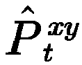


- In a movement process of the legged robot, the legged robot has stable movement and a small change amount in the direction of the z axis, so that


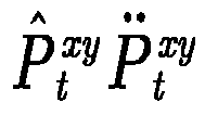

- In a movement process of the legged robot, when a gesture change of the legged robot is small, the change amount L̇ of the angular momentum corresponding to the legged robot is small and therefore can be ignored. Therefore, the third term on the right side of the equation in the relational data between the acting force to which at least one leg of the legged robot is subjected and the position of center of mass P(t) of the legged robot can be ignored. Then, the relational data between the acting force to which at least one leg of the legged robot is subjected and the position of center of mass P(t) of the legged robot is simplified, to obtain the following relation:


 represents a real number set in a multi-dimensional space; f 0{P(t)} is used for representing a sum of acting forces to which at least one leg in contact with the ground of the legged robot is subjected; H is a constant matrix; Wg is a constant vector;


- 3. Create second relational data based on relational data between an acting force to which at least one leg of the legged robot is subjected and a position of center of mass P(t) of the legged robot.
- By processing the relational data between an acting force to which at least one leg of the legged robot is subjected and a position of center of mass P(t) of the legged robot, the following relationship can be obtained:


- Through the foregoing relation, the second relational data corresponding to the ith leg of the legged robot can be obtained, and the following relationship is met:


- It can be known according to the foregoing second relational data that, the acting force fi {P(t)} corresponding to the ith leg of the legged robot and the fourth constant λ are in a linear relation.
- In this embodiment of this application, description is made by using the position of center of mass P(t) of the legged robot under an ideal condition; and in another embodiment, the position of center of mass P(t) of the legged robot has an error, and the position of center of mass P(t) of the legged robot in the movement process is affected by a leg of the legged robot, so that the position of center of mass P(t) of the legged robot changes within a specific range. To improve accuracy and stability of the obtained position of center of mass of the legged robot, a non-deterministic constraint is added to the error of the position of center of mass. As shown in
FIG. 6 , a point is taken in each of positive and negative directions of the x, y, and z axes of a coordinate system, to obtain a point 1, apoint 2, apoint 3, apoint 4, a point 5, and a point 6. The obtained six points are used as vertexes of a polyhedron, to obtain an offset


- After an offset


 represents a real number set in a multi-dimensional space; f 0{P(t)} is used for representing a sum of acting forces to which at least one leg in contact with the ground of the legged robot is subjected; m represents the mass of the legged robot;


- Through the relational data between the acting force to which at least one leg of the legged robot is subjected and the position of center of mass P(t) of the legged robot after an offset

- Third. Process of creating third relational data:
- The third relational data is created based on a friction force constraint to which the legged robot is subjected, the fourth relational data, and the fifth relational data.
- In a movement process of the legged robot, the legged robot is subjected to a friction force constraint: a leg in contact with the ground of the legged robot is subjected to a friction force greater than 0, and the friction force to which the leg is subjected is not less than a component force of an acting force fi {P(t)} to which the leg in contact with the ground is subjected in a friction force direction, to avoid generating relative slide between the leg and the ground, thereby ensuring that the legged robot can normally move. An acting force fi {P(t)} corresponding to each of at least one leg of the legged robot is subjected to a friction force constraint, and the following relationship is met:

 represents a real number set in a multi-dimensional space; t i1 and t i2 represent two tangent vectors on a plane perpendicular to the normal vector of the contact point in contact with the ground of the i th leg of the legged robot, the tangent vector t i1 and the tangent vector t i2 are orthogonal with each other, and
- In a movement process of the legged robot, the legged robot is subjected to a friction force constraint. Therefore, a direction of the acting force to which the i th leg in contact with the ground of the legged robot is subjected is within a cone, a contact point in contact with the ground of the i th leg is a vertex of the cone, and a connecting line within the cone from the vertex to any point of a base circle of the cone can be used as the direction of the acting force fi {P(t)} to which the i th leg in contact with the ground is subjected. To avoid introducing a nonlinear constraint, the cone is approximately presented as a rectangular pyramid, and the acting force fi {P(t)} to which the i th leg in contact with the ground meets the following relation:

 represents a real number set in a multi-dimensional space; t i1 and t i2 represent two tangent vectors on a plane perpendicular to the normal vector of the contact point in contact with the ground of the i th leg of the legged robot, the tangent vector t i1 and the tangent vector t i2 are orthogonal with each other, and


- Through the foregoing relation, through a constraint on component forces of the acting force fi {P(t)} to which the i th leg in contact with the ground of the legged robot is subjected on the four side surfaces of the rectangular pyramid, and a constraint on component forces of the acting force fi {P(t)} to which the i th leg in contact with the ground of the legged robot is subjected in the normal direction, the direction of the acting force fi {P(t)} to which the i th leg in contact with the ground of the legged robot is subjected is limited within the rectangular pyramid.
- Because the legged robot meets a friction force constraint at each of a plurality of sampling time points, the following is obtained by substituting the fourth relational data corresponding to the each sampling time point and the fifth relational data corresponding to the each sampling time point into the foregoing relation:


- Additionally, because the position of center of mass of the legged robot has the offset


- By substituting the fourth relational data corresponding to the each sampling time point into the fifth relational data, the obtained third relationship meets the following relation:

- Through a quadratic programming solver, the minimum value of the target value J in the third relational data can be obtained. Therefore, a variable matrix V corresponding to the minimum value of the target value J can be obtained, that is, the second constant Cfree and the fourth constant λ corresponding to the minimum value of the target value J are obtained, the first constant C whose value is determined is obtained through the second constant Cfree and the third constant h whose values are determined, and by substituting the first constant C whose value is determined into the first relational data, a trajectory of center of mass of the legged robot is obtained.
- Based on the method provided in this embodiment of this application, based on center of mass dynamics of the legged robot, a parameter slightly affecting the position of center of mass of the legged robot is ignored, and constraints of positions of center of mass, speeds, and accelerations in the initiation position and the termination position on the position of center of mass, and a friction force constraint to which the legged robot in contact with the ground is subjected are considered; determining the position of center of mass is converted in to a quadratic programming problem, to solve a trajectory of center of mass with high stability; and subsequently, with reference to the termination position of the foothold of the legged robot, a joint torque of each joint of the legged robot is obtained based on inverse kinematics, and the plurality of joints are controlled according to joint torques of the plurality of joints to rotate, to drive the legged robot to move.
- The method for determining the position of center of mass provided in this embodiment of this application is applicable to various legged robots, for example, a two-legged robot, a four-legged robot or a multi-legged robot; is applicable to various gaits of the legged robot, for example, two-legged walking, four-legged walking, four-legged jogging or a random gait; is applicable to various complex environments, for example, a flat ground, an uneven ground, a slope, or stairs; can use any order of the interval duration t , and can use any movement process in the process from the initiation position to the termination position; and can keep, in a case that the ground is a plane or has a relatively small height difference, the height of the center of mass of the robot unchanged, and use only 2 groups of curves to plan movement of the center of mass in the plane. Constraints of the state data in the initiation position and the state data in the termination position on the position of center of mass may be determined according to actual requirements, and it is necessary to ensure that a curve parameter having a constraint added still has an independent variable. When sampling time points are selected, sampling can be performed in any position on the trajectory of the position of center of mass, and a larger quantity of sampling time points indicates more proper distribution, and a more reliable movement trajectory of center of mass obtained, but a larger dimension and a longer solving time of the quadratic programming problem. Additionally, a distance corresponding to a sampling time point in the third relational data can be determined through a plurality of sampling time points, and the distance can include components in three directions of the x axis, the y axis, and the z axis, for which different weights can be selected according to an actual situation; and in addition to the acting force of the ground and the curve oscillation amplitude, a sum of squares of accelerations, a sum of squares of speed differences between neighboring points, a sum of squares of differences between accelerations, and the like can be further considered. Simplification of a cone of friction: approximation can be performed by using an inscribed pyramid with N (N>4) sloping sides of the cone of friction, and a larger value of N indicates more accurate approximation to the cone of friction, but a larger dimension and a longer solving time of the quadratic programming problem. Position of a contact point: the contact point is not merely limited to a contact point in contact with the ground on a leg of the legged robot, and is similarly applicable to a case that a part of the robot such as the body, the trunk, or the upper limb is in contact with an environment. Polyhedron whose position of center of mass has a non-deterministic constraint: any polyhedron meeting an actual requirement may be used, and an increase in the quantity of vertexes of the polyhedron causes increases in the dimension and the solving time of the quadratic programming problem. In a case that a position of center of mass in a single direction is determined and has a change that can be ignored, a polyhedron can be dimensionally reduced to a parallel polygon. In a case that positions of center of mass in two directions are determined and have changes that can be ignored, a polyhedron can be dimensionally reduced to a straight line. In a case that positions of center of mass in all three directions are determined and have changes that can be ignored, a polyhedron can be dimensionally reduced to a point.
- As shown in
FIG. 7 , a legged robot is configured with 4 legs, and the legged robot moves from an initiation position to a termination position according to a determined trajectory of center ofmass 701. - As shown in
FIG. 8 , a legged robot generates a trajectory of position of center of mass once in each half stepping period, and curve graphs of changes in a position of center of mass, a speed of center of mass, and an acceleration of center of mass of the legged robot with an interval duration are shown. Two curves in each curve graph respectively represent position of center of mass curves in which the highest powers of the interval duration t included in the position of center of mass P(t) are respectively 3 and 6. Three curve graphs in the first column inFIG. 8 are used for representing curves of changes in coordinates of the position of center of mass on the coordinate axes x, y, and z with the interval duration when the highest powers of the interval duration t included in the position of center of mass P(t) are respectively 3 and 6. Three curve graphs in the second column inFIG. 8 are used for representing curves of changes in component speed of the speed of center of mass on the coordinate axes x, y, and z with the interval duration when the highest powers of the interval duration t included in the position of center of mass P(t) are respectively 3 and 6. Three curve graphs in the third column inFIG. 8 are used for representing curves of changes in component acceleration of the acceleration of center of mass on the coordinate axes x, y, and z with the interval duration when the highest powers of the interval duration t included in the position of center of mass P(t) are respectively 3 and 6. The legged robot is configured with 4 legs, which are respectively a right rear leg, a right front leg, a left rear leg, and a left front leg, and a stepping sequence of the legged robot is stepping with the right rear leg, stepping with the right front leg, stepping with the left rear leg, and stepping with the left front leg. Optionally, each half stepping period is stepping with the right rear leg and stepping with the right front leg, or stepping with the left rear leg and stepping with the left front leg. The legged robot repeatedly performs the stepping process of the plurality of legs according to the stepping sequence, thereby enabling the legged robot to move. It can be known fromFIG. 8 that, a deviation between the position of center of mass curves in which the highest powers of the interval duration t included in the position of center of mass P(t) of the legged robot are respectively 3 and 6 is small, and therefore, it is determined that the highest power of the interval duration t included in the position of center of mass P(t) can be any value. - As shown in
FIG. 9 , a legged robot generates a trajectory of the position of center of mass once in each stepping period, and curve graphs of changes in a position of center of mass, a speed of center of mass, and an acceleration of center of mass of the legged robot with an interval duration are shown. Two curves in each curve graph respectively represent position of center of mass curves in which the highest powers of the interval duration t included in the position of center of mass P(t) are respectively 3 and 6. Three curve graphs in the first column inFIG. 9 are used for representing curves of changes in coordinates of the position of center of mass on the coordinate axes x, y, and z with the interval duration when the highest powers of the interval duration t included in the position of center of mass P(t) are respectively 3 and 6. Three curve graphs in the second column inFIG. 9 are used for representing curves of changes in component speed of the speed of center of mass on the coordinate axes x, y, and z with the interval duration when the highest powers of the interval duration t included in the position of center of mass P(t) are respectively 3 and 6. Three curve graphs in the third column inFIG. 9 are used for representing curves of changes in component acceleration of the acceleration of center of mass on the coordinate axes x, y, and z with the interval duration when the highest powers of the interval duration t included in the position of center of mass P(t) are respectively 3 and 6. The legged robot is configured with 4 legs, which are respectively a right rear leg, a right front leg, a left rear leg, and a left front leg, and a stepping sequence of the legged robot is stepping with the right rear leg, stepping with the right front leg, stepping with the left rear leg, and stepping with the left front leg. Optionally, each stepping period is stepping with the right rear leg, stepping with the right front leg, stepping with the left rear leg, and stepping with the left front leg. The legged robot repeatedly performs the stepping process of the plurality of legs according to the stepping sequence, thereby enabling the legged robot to move. It can be known fromFIG. 9 that, a deviation between the position of center of mass curves in which the highest powers of the interval duration t included in the position of center of mass P(t) of the legged robot are respectively 3 and 6 is small, and therefore, it is determined that the highest power of the interval duration t included in the position of center of mass P(t) can be any value. - As shown in
FIG. 10 , when the highest power of the interval duration t included in the position of center of mass P(t) of the legged robot is 6, the first row of images represents curves indicating that the legged robot generates a trajectory of the position of center of mass once in each half stepping period, and a total torque and an omitted torque of the legged robot change with the interval duration. Three curve graphs in the first row inFIG. 10 represents curves of changes in component torques of the total torque and the omitted torque of the legged robot on the coordinate axes x, y, and z with the interval duration when the legged robot generates a trajectory of the position of center of mass once in each half stepping period. The second row of images represents curves indicating that the legged robot generates a trajectory of the position of center of mass once in each stepping period, and a total torque and an omitted torque of the legged robot change with the interval duration. Three curve graphs in the second row inFIG. 10 represents curves of changes in component torques of the total torque and the omitted torque of the legged robot on the coordinate axes x, y, and z with the interval duration when the legged robot generates a trajectory of the position of center of mass once in each stepping period. It can be known fromFIG. 10 that, the torque omitted when the position of center of mass is determined in the foregoing embodiment is close to 0, indicating that the torque can be ignored. -
FIG. 11 shows curves of changes of the position of center of mass determined by the legged robot for the legged robot according to the method for determining the position of center of mass in the foregoing embodiment and the position of center of mass of the legged robot with the interval duration. InFIG. 11 , the first row of images represents curves of changes in the position of center of mass with the interval duration when the legged robot slowly moves, and the second row of images represents curves of changes in the position of center of mass with the interval duration when the legged robot quickly moves. It can be known fromFIG. 11 that, the position of center of mass determined for the legged robot through the method for determining the position of center of mass provided in the foregoing embodiment coincides with the position of center of mass of the legged robot, thereby determining that the method for determining the position of center of mass provided in this embodiment of this application is accurate. - In the following embodiment, third relational data is created through a state data error between second state data of a legged robot in a termination position and prediction state data, and then a movement trajectory of the legged robot is determined through the third relational data.
FIG. 12 is a flowchart of a method for determining a position of center of mass according to an embodiment of this application, applicable to a legged robot. As shown inFIG. 12 , the method includes the following steps. - 1201. Obtain second state data of the legged robot in a termination position.
- The second state data includes at least a target position of center of mass. Optionally, the target position of center of mass is represented in the form of coordinates in a coordinate system or in the form of a vector. For example, in a world coordinate system, the target position of center of mass of the legged robot is [20, 35, 80].
- In a possible implementation, the second state data includes a target position of center of mass, and
step 1201 includes: obtaining, in a case that the legged robot is in the termination position, a position of a contact point in contact with the ground of the at least one leg configured for the legged robot; and determining the target position of center of mass based on the position of the contact point of the at least one leg. - For example, the legged robot is a four-legged robot. When the legged robot moves to the termination position, four legs of the four-legged robot are all in contact with the ground. Therefore, four contact positions in contact with the ground on the four legs are obtained, and based on the four contact positions, the target position of center of mass of the legged robot in the termination position is determined.
- The center of mass is the center of mass of the legged robot, and the position of center of mass is a position of the center of mass of the legged robot. The target position of center of mass is a position of the center of mass of the legged robot intended when the legged robot moves to the termination position.
- The termination position is a position to be reached by the legged robot. In this case, the legged robot has not reached the termination position. The termination position is determined by the legged robot based on an environment in which the legged robot is located. Optionally, the legged robot obtains, through a vision perception system, an image including an environment in a movement direction of the legged robot, performs feature extraction on the image including the environment, determines the termination position of the legged robot, determines the second state data for the termination position, and determines, a position of a contact point in contact with the ground on the at least one leg when the legged robot is in the termination position.
- For example, the vision perception system includes a camera, and the legged robot photographs the environment in the movement direction of the legged robot through the camera, to obtain the image including the environment in the movement direction of the legged robot.
- Optionally, based on contact positions in contact with the ground on a plurality of legs of the legged robot, a center position of the plurality of contact positions is determined; and based on the height of the legged robot and the center position, the target position of center of mass is determined.
- For example, in a world coordinate system, a coordinate system with a right-h and rule is used, a movement direction of the legged robot is used as the X axis, a direction on the left side of the legged robot and perpendicular to the X axis is used as the Y axis, and a direction perpendicular to the ground is used as the Z axis; and through contact positions on a plurality of legs of the legged robot, a center position of the plurality of contact positions is determined, and a coordinate value of the center position on the Z axis is added to the height value of the legged robot, to obtain a coordinate value of the target position of center of mass in the world coordinate system, that is, the target position of center of mass is determined.
- In a possible implementation, the second state data further includes a target speed of center of mass, and step 1201 further includes: obtaining first state data of the legged robot in an initiation position, where the first state data includes at least an initiation position of center of mass; and determining a ratio of a distance between the target position of center of mass and the initiation position of center of mass to the target movement duration as the target speed of center of mass.
- The initiation position is a current position of the legged robot, and the initiation position of center of mass is a current position of the center of mass of the legged robot. A speed of center of mass is a movement speed of the center of mass of the legged robot, and the speed of center of mass can be represented with a vector. The target speed of center of mass is a movement speed of the center of mass of the legged robot intended when the legged robot moves to the termination position.
- The distance between the target position of center of mass and the initiation position of center of mass represents a movement distance of the center of mass of the legged robot in the process that the legged robot moves from the initiation position to the termination position. The target movement duration indicates a duration required for the legged robot to move from the initiation position to the termination position. Optionally, the target movement duration is any duration, for example, 2 seconds or 3 seconds. Through a ratio of the distance to the target movement duration, a speed at which the legged robot moves from the initiation position to the termination position, that is, a target speed of center of mass at which the legged robot moves to the termination position can be determined. Optionally, the target speed of center of mass is represented in the form of a vector.
- For example, a position of center of mass of the legged robot is represented in the form of a vector, for example, [1, 2, 3], and all elements in the vector respectively represent coordinate values of the center of mass of the legged robot on the x axis, the y axis, and the z axis of the coordinate system. Therefore, the distance between the target position of center of mass and the initiation position of center of mass is also represented with a vector, representing displacements of the center of mass of the legged robot on the x axis, the y axis, and the z axis, and a ratio of the distance to the target movement duration is component speeds of the target speed of center of mass on the x axis, the y axis, and the z axis.
- In a possible implementation, the second state data further includes a target acceleration of center of mass, and the first state data further includes an initiation speed of center of mass; and
step 1201 further includes: determining a ratio of a difference between the target speed of center of mass and the initiation speed of center of mass to the target movement duration as the target acceleration. - The target acceleration of center of mass is an acceleration of the center of mass of the legged robot intended when the legged robot moves to the termination position. Optionally, the target acceleration of center of mass is represented in the form of a vector. The initiation speed of center of mass indicates a speed of the center of mass of the legged robot when the legged robot is in the initiation position. Optionally, the initiation speed of center of mass is represented in the form of a vector.
- A difference between the target speed of center of mass and the initiation speed of center of mass indicates a speed of center of mass change amount of the legged robot when the legged robot moves from the initiation position to the termination position, and a ratio of the change amount of the speed of center of mass to the target movement duration is a change amount of the speed of center of mass per unit time of the legged robot when the legged robot moves from the initiation position to the termination position, that is, the target acceleration of center of mass of the legged robot at the time of moving to the termination position.
- In a possible implementation, the second state data includes at least a target position of center of mass, a target speed of center of mass, and a target acceleration of center of mass, and therefore step 1201 includes: obtaining, in a case that the legged robot is in the termination position, a position of a contact point in contact with the ground of the at least one leg configured for the legged robot; and determining the target position of center of mass based on the position of the contact point of the at least one leg; obtaining first state data of the legged robot in an initiation position, where the first state data includes at least an initiation position of center of mass, and determining a ratio of a distance between the target position of center of mass and the initiation position of center of mass to the target movement duration as the target speed of center of mass; and determining a ratio of a difference between the target speed of center of mass and the initiation speed of center of mass to the target movement duration as the target acceleration.
- 1202. Create first relational data, the first relational data indicating a relationship between an interval duration t and a position of center of mass P(t) of the legged robot.
- The interval duration t indicates a duration of an interval between any time point in a process that the legged robot moves from an initiation position to a termination position and a start time point corresponding to the initiation position. The position of center of mass P(t) indicates a position of center of mass of the legged robot within the interval duration t. The first relational data includes a first constant C whose value is not determined, and the first constant C is used for representing a relationship between the position of center of mass P(t) and the interval duration t. Optionally, the first constant C is represented in the form of a vector or a matrix.
- In the legged robot, the first relational data is stored in the form of a descriptive statement or a function.
- In a possible implementation,
step 1202 includes: the first relational data is set as follows: the position of center of mass P(t) is a product of the first constant C and a duration matrix E . - The duration matrix E is a matrix used for representing the interval duration t.
- Optionally, the first relational data meets the following relation:

- Because the position of center of mass of the legged robot changes with a moving interval duration t in a movement process of the legged robot, the position of center of mass after any interval duration t has a corresponding change amount of position of center of mass, and a sum of the change amount of the position of center of mass corresponding to the interval duration t and the initiation position of center of mass of the legged robot at the beginning of movement is used as the corresponding position of center of mass P(t) of the legged robot after any interval duration t, thereby determining the first relational data indicating a relationship between the position of center of mass P(t) and the interval duration t, and subsequently determining the trajectory of center of mass of the legged robot through the first relational data.
- 1203. Determine, based on a target movement duration and the first relational data, prediction state data of the legged robot in the termination position.
- The first relational data is used for representing a position of center of mass at any time point in the process that the legged robot moves from the initiation position to the termination position, and the target movement duration indicates a duration required for the legged robot to move from the initiation position to the termination position. Therefore, through the target movement duration and the first relational data, the prediction position of center of mass of the legged robot when the legged robot moves to the termination position according to the trajectory of center of mass indicated by the first relational data can be predicted. Because the first relational data includes the first constant C whose value is not determined, the obtained prediction position of center of mass is related to the first constant C whose value is not determined.
- In a possible implementation, the prediction state data includes a prediction position of center of mass, and
step 1203 includes: determining, based on the first relational data, the prediction position of center of mass of the legged robot after the target movement duration elapses from an initiation position. - The first relational data indicates a relationship between the interval duration t and the position of center of mass P(t) of the legged robot, and the first relational data includes the first constant C whose value is not determined. Therefore, the target movement duration is used as the interval duration t and substituted into the first relational data, to obtain the prediction position of center of mass of the legged robot, and the prediction position of center of mass is related to the first constant C whose value is not determined.
- In a possible implementation, the prediction state data includes a prediction speed of center of mass, and
step 1203 includes: creating, based on the first relational data, relational data between the interval duration t and a speed of center of mass of the legged robot; and determining, based on the relational data between the interval duration t and the speed of center of mass of the legged robot, the prediction speed of center of mass of the legged robot after the target movement duration elapses from an initiation position. - The prediction speed of center of mass is a speed of center of mass of the legged robot predicted through the first relational data when the legged robot moves to the termination position, and the prediction speed of center of mass is related to the first constant C whose value is not determined.
- Optionally, the first-order derivative of the first relational data with respect to the interval duration t is obtained, to obtain relational data between the interval duration t and the speed of center of mass of the legged robot, and the target movement duration is substituted into the relational data, to obtain the prediction speed of center of mass.
- In a possible implementation, the prediction state data includes a prediction acceleration of center of mass, and
step 1203 includes: creating, based on the first relational data, relational data between the interval duration t and an acceleration of center of mass of the legged robot; and determining, based on the relational data between the interval duration t and the acceleration of center of mass of the legged robot, the prediction acceleration of center of mass of the legged robot after the target movement duration elapses from an initiation position. - The prediction acceleration of center of mass is an acceleration of center of mass of the legged robot predicted through the first relational data when the legged robot moves to the termination position, and the prediction acceleration of center of mass is related to the first constant C whose value is not determined.
- Optionally, the second-order derivative of the first relational data with respect to the interval duration t is obtained, to obtain relational data between the interval duration t and the acceleration of center of mass of the legged robot, and the target movement duration is substituted into the relational data, to obtain the prediction acceleration of center of mass.
- In a possible implementation, the prediction state data includes at least a prediction position of center of mass, a prediction speed of center of mass, and a prediction acceleration of center of mass, and therefore step 1203 includes: determining, based on the first relational data, the prediction position of center of mass of the legged robot after the target movement duration elapses from an initiation position; creating, based on the first relational data, relational data between the interval duration t and a speed of center of mass of the legged robot; and determining, based on the relational data between the interval duration t and the speed of center of mass of the legged robot, the prediction speed of center of mass of the legged robot after the target movement duration elapses from an initiation position; and creating, based on the first relational data, relational data between the interval duration t and an acceleration of center of mass of the legged robot; and determining, based on the relational data between the interval duration t and the acceleration of center of mass of the legged robot, the prediction acceleration of center of mass of the legged robot after the target movement duration elapses from an initiation position.
- 1204. Create second relational data corresponding to at least one leg configured for the legged robot.
- The second relational data corresponding to the at least one leg separately indicating a relationship between an acting force fi corresponding to the at least one leg and the position of center of mass P(t). The acting force fi indicates an acting force to which the i th leg in contact with the ground of the legged robot is subjected, and i is a positive integer. The second relational data includes the first constant C whose value is not determined. in the legged robot, the second relational data is stored in the form of a descriptive statement or a function.
- In a possible implementation,
step 1204 includes: creating sixth relational data, creating seventh relational data, and creating, based on the sixth relational data and the seventh relational data, the second relational data corresponding to the at least one leg. - The sixth relational data indicates a relationship between an angular momentum L of the legged robot and the interval duration t, and the angular momentum L is used for representing a change in a gesture of the legged robot. The seventh relational data indicates a positive correlation between the acting force fi(L) corresponding to the at least one leg and the angular momentum L . The seventh relational data is used for representing an effect of the gesture of the legged robot on the acting force corresponding to the at least one leg of the legged robot. Through the sixth relational data and the seventh relational data that are created, a relationship between the acting force fi to which the at least one leg in contact with the ground of the legged robot is subjected and the interval duration t is determined.
- In the legged robot, the sixth relational data and the seventh relational data are stored in the form of descriptive statements or functions.
- 1205. Create the third relational data based on a state data error between the second state data and the prediction state data.
- The third relational data indicates a positive correlation between the target value J and the state data error and a square of an acting force fi to which the at least one leg in contact with the ground is subjected. Because the prediction position of center of mass is related to the first constant C , the state data error is also related to the first constant C . Therefore, the target value J is related to the first constant C , that is, the third relational data includes the first constant C whose value is not determined. in the legged robot, the third relational data is stored in the form of a descriptive statement or a function.
- In a possible implementation, a square of a product of each acting force fi and a corresponding weight is determined, and a sum of squares corresponding to an acting force f i corresponding to at least one leg is used as a weighted sum of squares of the acting force fi corresponding to the at least one leg. Optionally, a weight corresponding to each acting force fi is arbitrarily set by the legged robot.
- Optionally, the acting force fi to which the at least one leg in contact with the ground of the legged robot is subjected includes fi
x , fiy , and fiz , the acting force fix is a component force of the acting force fi on the x axis, the acting force fiy is a component force of the acting force fi on the y axis, the acting force fiz is a component force of the acting force fi on the z axis, and for the i th leg in contact with the ground of the legged robot, a weighted square of the acting force fi corresponding to the leg meets the following relation
- Optionally, a weighted sum of squares of the acting force fi corresponding to the at least one leg in contact with the ground of the legged robot is equal to a sum of weighted squares Fi corresponding to the at least one leg.
- In a possible implementation, the second state data includes a target position of center of mass, and the prediction state data includes a prediction position of center of mass; and
step 1205 includes: determining a first difference between the target position of center of mass and the prediction position of center of mass; and setting the target value J to a sum value of a weighted sum of squares of the acting force fi corresponding to the at least one leg, and a square of the first difference. - The first difference is used for indicating a difference between the target position of center of mass and the prediction position of center of mass when the legged robot is in the termination position. Because the prediction position of center of mass is related to the first constant C, the first difference is related to the first constant C, and after the target value J is set to the sum value of the weighted sum of squares of the acting force fi corresponding to the at least one leg, and the square of the first difference, the target value J is related to a quadratic term of the first constant C . Optionally, when the first constant C includes a plurality of constant terms, quadratic terms of the first constant C include quadratic constant terms formed by the plurality of constant terms, that is, a square of each constant term or a product of any two constant terms. For example, the first constant C includes constant terms Cx, Cy, and Cz, and therefore the quadratic terms of the first constant C include quadratic constant terms such as


- Optionally, a distance between the target position of center of mass and the prediction position of center of mass is determined as the first difference.
- Optionally, each of the target position of center of mass and the prediction position of center of mass is represented in the form of coordinates, and therefore the first difference is also represented in the form of coordinates. The target position of center of mass includes first coordinate values on the x, y, and z axes, the prediction position of center of mass includes second coordinate values on the x, y, and z axes, and differences between the first coordinate values and the second coordinate values on the x, y, and z axes are determined, to obtain the first difference. The first difference includes differences on the x, y, and z axes, and a weighted sum of squares of the differences of the first difference on the x, y, and z axes is used as a square of the first difference. Optionally, weights corresponding to the x, y, and z axes are arbitrarily set by the legged robot.
- In a possible implementation, the second state data includes a target speed of center of mass, and the prediction state data includes a prediction speed of center of mass; and
step 1205 includes: determining a third difference between the target speed of center of mass and the prediction speed of center of mass; and setting the target value J to a sum value of a weighted sum of squares of the acting force fi corresponding to the at least one leg, and a square of the third difference. - The third difference is used for indicating a difference between the target speed of center of mass of the legged robot and the prediction speed of center of mass when the legged robot is in the termination position. Because the prediction speed of center of mass is related to the first constant C , the third difference is related to the first constant C , and after the target value J is set to the sum value of the weighted sum of squares of the acting force fi corresponding to the at least one leg, and the square of the third difference, the target value J is related to a quadratic term of the first constant C . Optionally, when the first constant C includes a plurality of constant terms, quadratic terms of the first constant C include quadratic constant terms formed by the plurality of constant terms, that is, a square of each constant term or a product of any two constant terms. For example, the first constant C includes constant terms Cx, Cy, and Cz, and therefore the quadratic terms of the first constant C include quadratic constant terms such as


- Optionally, each of the target speed of center of mass and the prediction speed of center of mass is represented in the form of coordinates, and therefore the third difference is also represented in the form of coordinates. The target speed of center of mass includes first component speeds on the x, y, and z axes, the prediction speed of center of mass includes second component speeds on the x, y, and z axes, and speed differences between the first component speeds and the second component speeds on the x, y, and z axes are determined, to obtain the third difference. The third difference includes speed differences on the x, y, and z axes, and a weighted sum of squares of the speed differences of the third difference on the x, y, and z axes is used as a weighted square of the third difference. x, y, and z axes are arbitrarily set by the legged robot.
- In a possible implementation, the second state data includes a target acceleration of center of mass, and the prediction state data includes a prediction acceleration of center of mass; and
step 1205 includes: determining a second difference between the target acceleration of center of mass and the prediction acceleration of center of mass; and setting the target value J to a sum value of a weighted sum of squares of the acting force fi corresponding to the at least one leg, and a square of the second difference. - The second difference is used for indicating a difference between the target acceleration of center of mass of the legged robot and the prediction acceleration of center of mass when the legged robot is in the termination position. Because the prediction acceleration of center of mass is related to the first constant C , the second difference is related to the first constant C, and after the target value J is set to the sum value of the weighted sum of squares of the acting force fi corresponding to the at least one leg, and the square of the third difference, the target value J is related to a quadratic term of the first constant C . Optionally, when the first constant C includes a plurality of constant terms, quadratic terms of the first constant C include quadratic constant terms formed by the plurality of constant terms, that is, a square of each constant term or a product of any two constant terms. For example, the first constant C includes constant terms Cx, Cy, and Cz, and therefore the quadratic terms of the first constant C include quadratic constant terms such as


- Optionally, each of the target acceleration of center of mass and the prediction acceleration of center of mass is represented in the form of coordinates, and therefore the second difference is also represented in the form of coordinates. The target acceleration of center of mass includes first component accelerations on the x, y, and z axes, the prediction acceleration of center of mass includes second component accelerations on the x, y, and z axes, and acceleration differences between the first component accelerations and the second component accelerations on the x, y, and z axes are determined, to obtain the second difference. The second difference includes acceleration differences on the x, y, and z axes, and a weighted sum of squares of the acceleration differences of the second difference on the x, y, and z axes is used as a weighted square of the second difference. x, y, and z axes are arbitrarily set by the legged robot.
- The three possible implementations of the foregoing
step 1205 are respectively described only by using state data including positions of center of mass, speeds of center of mass, or accelerations of center of mass. Additionally, any two of the foregoing three possible implementations can be combined, or the three possible implementations are combined. - When any two possible implementations are combined, if the state data error includes the first difference and the second difference, the target value J is set to a sum value of a weighted sum of squares of the acting force fi corresponding to the at least one leg and a weighted sum of squares of the first difference and the second difference; or if the state data error includes the first difference and the third difference, the target value J is set to a sum value of a weighted sum of squares of the acting force fi corresponding to the at least one leg and a weighted sum of squares of the first difference and the third difference; or if the state data error includes the second difference and the third difference, the target value J is set to a sum value of a weighted sum of squares of the acting force fi corresponding to the at least one leg and a weighted sum of squares of the second difference and the third difference. Weights of any two differences included in the state data error are arbitrarily set by the legged robot.
- When the foregoing three possible implementations are combined, that is, the state data error includes the first difference, the second difference, and the third difference, the target value J is set to a sum value of a weighted sum of squares of the acting force fi corresponding to the at least one leg and a weighted sum of squares of the first difference, the second difference, and the third difference. Optionally, weights of the first difference, the second difference, and the third difference are arbitrarily set by the legged robot. After the weighted square of the first difference, the weighted square of the second difference, and the weighted square of the third difference are determined, a sum of the weighted square of the first difference, the weighted square of the second difference, and the weighted square of the third difference is used as a weighted sum of squares of the first difference, the second difference, and the third difference.
- In a possible implementation,
step 1205 includes the following steps 12051 to 12053: - 12051. Select a plurality of sampling time points within the target movement duration.
- A sampling time point refers to a time point between a start time point corresponding to the initiation position and a target time point corresponding to the termination position. The plurality of sampling time points include two or more sampling time points. Interval durations between any two neighboring sampling time points may be equal or not equal.
- For example, the movement duration is 60 seconds, the start time point corresponding to the initiation position is the 0th second, the target time point corresponding to the termination position is the 60th second, and 5 sampling time points are selected within the movement duration. The first sampling time point is the 10th second, the second sampling time point is the 20th second, the third sampling time point is the 120th second, the fourth sampling time point is the 40th second, and the fifth sampling time point is the 50th second; or the first sampling time point is the 5th second, the second sampling time point is the 20th second, the third sampling time point is the 25th second, the fourth sampling time point is the 40th second, and the fifth sampling time point is the 55th second.
- In a possible implementation, step 12051 includes: the movement duration is divided in to a plurality of time periods, and an end time point of each time period is used as a sampling time point. The obtained plurality of time periods may be equal or not equal.
- 12052. Determine, based on an interval duration between each sampling time point and a start time point and the first relational data, fourth relational data corresponding to the each sampling time point.
- The fourth relational data indicates a relationship between the first constant C and a sampling position of center of mass Q(C), and the sampling position of center of mass Q(C) indicates a position of center of mass of the legged robot at the corresponding sampling time point. in the legged robot, the fourth relational data is stored in the form of a descriptive statement or a function.
- The first relational data indicates that the position of center of mass P(t) is a product of the first constant C and the duration matrix E . Therefore, by substituting an interval duration between any sampling time point and the start time point into the duration matrix E in the first relational data, the value of the duration matrix E at the any sampling time point is determined, to obtain the fourth relational data corresponding to the sampling time point, where the fourth relational data indicates a relationship between the first constant C and the sampling position of center of mass Q (C) . The value of the first constant C included in the fourth relational data is not determined, but values of other first constants included in the fourth relational data have all been determined.
- 12053. Create the third relational data based on the state data error and the fourth relational data.
- The third relational data indicates a positive correlation between the target value J and a square of the acting force fi corresponding to the at least one leg corresponding to the each sampling time point, the state data error, and the sampling position of center of mass Q(C).
- In a possible implementation, the second state data includes a target position of center of mass, and the prediction state data includes a prediction position of center of mass; and step 12053 includes: determining a first difference between the target position of center of mass and the prediction position of center of mass; and setting the target value J to a sum value of a first value, a second value, and a third value.
- The first value is a square of the first difference, and the second value is a weighted sum of squares of a plurality of distances. The plurality of distances include a distance between any two neighboring positions of center of mass of an initiation position of center of mass in an initiation position, a plurality of sampling positions of center of mass, and the prediction position of center of mass, and the third value is a weighted sum of squares of the acting force fi corresponding to the at least one leg corresponding to the each sampling time point. Optionally, a weight of each distance is arbitrarily set by the legged robot. A squared value of a product of each distance and a corresponding weight is determined, and a sum of squared values corresponding to a plurality of distances is used as a weighted sum of squares of the plurality of distances. The weighted sum of squares of the plurality of distances can reflect the length of the trajectory of center of mass, and can reduce the oscillation amplitude of the trajectory of center of mass curve.
- Because the plurality of sampling positions and the prediction position of center of mass are all related to the first constant C , the first difference and the plurality of distances are all related to the first constant C . The first value is the square of the first difference, and the second value is the weighted sum of squares of the plurality of distances. Therefore, the first value and the second value are both related to the quadratic terms of the first constant C, and after the target value J is set to the sum value of the first value, the second value, and the third value, the target value J is related to the quadratic terms of the first constant C . Optionally, when the first constant C includes a plurality of first constant terms, quadratic terms of the first constant C include quadratic first constant terms formed by the plurality of first constant terms, that is, a square of each first constant term or a product of any two first constant terms. For example, the first constant C includes first constant terms (Cx, Cy, and Cz, and therefore the quadratic terms of the first constant C include quadratic first constant terms such as


- In a possible implementation, the second state data includes a target speed of center of mass, and the prediction state data includes a prediction speed of center of mass; and step 12053 includes: determining a third difference between the target speed of center of mass and the prediction speed of center of mass; and setting the target value J to a sum value of a second value, a third value, and a fifth value.
- The fifth value is a square of the third difference, and the second value is a weighted sum of squares of a plurality of distances. The third value is a weighted sum of squares of the acting force fi corresponding to the at least one leg corresponding to the each sampling time point.
- Because the plurality of sampling positions and the prediction speed of center of mass are all related to the first constant C , the third difference and the plurality of distances are all related to the first constant C. The fifth value is the square of the third difference, and the second value is the weighted sum of squares of the plurality of distances. Therefore, the fifth value and the second value are both related to the quadratic terms of the first constant C, and after the target value J is set to the sum value of the second value, the third value, and the fifth value, the target value J is related to the quadratic terms of the first constant C . Optionally, when the first constant C includes a plurality of first constant terms, quadratic terms of the first constant C include quadratic first constant terms formed by the plurality of first constant terms, that is, a square of each first constant term or a product of any two first constant terms. For example, the first constant C includes first constant terms Cx , Cy , and Cz, and therefore the quadratic terms of the first constant C include quadratic first constant terms such as


- In a possible implementation, the second state data includes a target acceleration of center of mass, and the prediction state data includes a prediction acceleration of center of mass; and step 12053 includes: determining a second difference between the target acceleration of center of mass and the prediction acceleration of center of mass; and setting the target value J to a sum value of a second value, a third value, and a fourth value.
- The fourth value is a square of the second difference, and the second value is a weighted sum of squares of a plurality of distances. The third value is a weighted sum of squares of the acting force fi corresponding to the at least one leg corresponding to the each sampling time point.
- Because the plurality of sampling positions and the prediction acceleration of center of mass are all related to the first constant C, the second difference and the plurality of distances are all related to the first constant C . The fourth value is the square of the second difference, and the second value is the weighted sum of squares of the plurality of distances. Therefore, the fourth value and the second value are both related to the quadratic terms of the first constant C, and after the target value J is set to the sum value of the second value, the third value, and the fourth value, the target value J is related to the quadratic terms of the first constant C . Optionally, when the first constant C includes a plurality of first constant terms, quadratic terms of the first constant C include quadratic first constant terms formed by the plurality of first constant terms, that is, a square of each first constant term or a product of any two first constant terms. For example, the first constant C includes first constant terms Cx , Cy, and Cz, and therefore the quadratic terms of the first constant C include quadratic first constant terms such as


- The three possible implementations of the foregoing step 12053 are respectively described only by using state data including positions of center of mass, speeds of center of mass, or accelerations of center of mass. Additionally, any two of the foregoing three possible implementations can be combined, or the three possible implementations are combined.
- When any two possible implementations are combined, if the state data error includes the first difference and the second difference, the target value J is set to a sum value of a weighted sum of squares of the first difference and the second difference, the second value, and the third value; or if the state data error includes the first difference and the third difference, the target value J is set to a sum value of a weighted sum of squares of the first difference and the third difference, the second value, and the third value; or if the state data error includes the second difference and the third difference, the target value J is set to a sum value of a weighted sum of squares of the second difference and the third difference, the second value, and the third value. Weights of any two differences included in the state data error are arbitrarily set by the legged robot.
- When the foregoing three possible implementations are combined, that is, the state data error includes the first difference, the second difference, and the third difference, the target value J is set to a sum value of a weighted sum of squares of the first difference, the second difference, and the third difference, the second value, and the third value.
- Optionally, weights of the first difference, the third difference, and the second difference are arbitrarily set by the legged robot. A squared value of a product of the first difference and the corresponding weight, a squared value of a product of the third difference and the corresponding weight, and a squared value of a product of the second difference and the corresponding weight are determined, and a sum of the squared value corresponding to the first difference, the squared value corresponding to the third difference, and the squared value corresponding to the second difference is a weighted sum of squares of the first difference, the third difference, and the second difference.
- 1206. Create eighth relational data, ninth relational data, and tenth relational data based on the first relational data and a start time point.
- The eighth relational data indicates a relationship between an initiation position of center of mass of the legged robot in an initiation position and the first constant C , the ninth relational data indicates a relationship between an initiation speed of center of mass of the legged robot in the initiation position and the first constant C , and the tenth relational data indicates a relationship between an initiation acceleration of center of mass of the legged robot in the initiation position and the first constant C . in the legged robot, the eighth relational data, the ninth relational data, and the tenth relational data are stored in the form of descriptive statements or functions.
- In a possible implementation,
step 1206 includes: substituting the start time point into the first relational data, to obtain the eighth relational data; obtaining a first-order derivative of the first relational data with respect to the interval duration t, and substituting the start time point into relational data of the obtained first-order derivative, to obtain the ninth relational data; and obtaining a second-order derivative of the first relational data with respect to the interval duration t, and substituting the start time point into relational data of the obtained second-order derivative, to obtain the tenth relational data. - 1207. Determine, based on the eighth relational data, the ninth relational data, the tenth relational data, the second relational data, and the third relational data, a value of the first constant C at which a target value J has a minimum value.
- In a case that the first constant C meets the eighth relational data, the ninth relational data, the tenth relational data, and the second relational data, the value of the first constant C at which the target value J has the minimum value is determined, so that the first state data of the legged robot in the initiation position meets the first relational data corresponding to the first constant C whose value is determined, and the acting force corresponding to the at least one leg in the initiation position meets the second relational data, to ensure accuracy of the determined value of the first constant C .
- In a possible implementation, a friction force constraint condition is created, the friction force constraint condition indicates a friction force constraint condition met by the acting force to which the at least one leg in contact with the ground of the legged robot is subjected, and the friction force constraint condition includes the first constant C whose value is not determined. In a case that the friction force constraint condition is met, the value of the first constant C at which the target value J has the minimum value is determined based on the eighth relational data, the ninth relational data, the tenth relational data, the second relational data, and the third relational data.
- In this application, description is made by using an example in which the value of the first constant C at which the target value J has the minimum value is determined based on the eighth relational data, the ninth relational data, the tenth relational data, the second relational data, and the third relational data; and in another embodiment, it is unnecessary to perform
steps 1206 to 1207, and the value of the first constant C at which the target value J has the minimum value can be determined based on the second relational data and the third relational data in another manner. - 1208. Obtain the first relational data corresponding to the first constant C whose value is determined.
- After the value of the first constant C is determined, if the first constant C whose value is determined is substituted into the first relational data, the first relational data indicates a relationship between the position of center of mass P(t 0) and the interval duration t; and except the interval duration t, the first relational data does not include other first constants whose values are not determined. Therefore, the first relational data corresponding to the first constant C whose value is determined can represent a trajectory of center of mass of the legged robot.
- 1209. Determine, based on the first relational data, a position of center of mass P(t 0 ) of the legged robot within any interval duration t 0 in a movement process of the legged robot.
- This step is similar to step 311. Details are not described herein again.
- 1210. Determine, based on the position of center of mass P(t 0) and the termination position, joint torques of a plurality of joints of the legged robot.
- This step is similar to step 312. Details are not described herein again.
- 1211. Control, according to the joint torques of the plurality of joints, the plurality of joints to rotate, to drive the legged robot to move.
- This step is similar to step 313. Details are not described herein again.
- In this embodiments of this application, a movement process that the legged robot moves from the initiation position to the termination position is describes; and in another embodiment, after reaching the termination position, the legged robot can further continue to perform the latter movement process, to perform the foregoing
steps 1201 to 1211 by using the termination position of the former movement process as the initiation position of the latter movement process, so that the legged robot moves to the termination position of the latter process, thereby implementing a plurality of consecutive movement processes of the legged robot. - In a possible implementation, the termination position of the last movement process is used as a target position of the legged robot, and after it is determined that the legged robot moves to the termination position of the current movement process, it is detected whether the termination position coincides with the target position. In response to that the termination position does not coincide with the target position, the first state data is determined for the termination position. In response to that the termination position coincides with the target position, the second state data is determined for the termination position.
- In this embodiment of this application, description is made by using the legged robot as an execution body; and in another embodiment, the foregoing
steps 1201 to 1211 are performed by a server, the server determines, based on the position of center of mass P(t 0) and the termination position, the joint torques of the plurality of joints of the legged robot, and sends a movement instruction to the legged robot, where the movement instruction carries the joint torques of the plurality of joints, and the legged robot controls, according to the joint torques of the plurality of joints, the plurality of joints to rotate, to drive the legged robot to move. - In a possible implementation, the server establishes communicative connection to the plurality of joints of the legged robot, the server sends a rotating instruction to the plurality of joints of the legged robot according to the determined joint torques of the plurality of joints, where the rotating instruction carries the joint torques of the corresponding joints, and after receiving the rotating instruction, the plurality of joints of the legged robot rotate according to the corresponding joint torques, to drive the legged robot to move.
- In this embodiments of this application, description is made by using the legged robot as an execution body; and in another embodiment, the foregoing
steps 1201 to 1208 are performed by the server. After obtaining the first relational data corresponding to the first constant C whose value is determined, the server sends the first relational data corresponding to the first constant C whose value is determined to the legged robot, and the legged robot performssteps 1209 to 1211, thereby controlling the legged robot to move. - Based on the method provided in this embodiment of this application, it is unnecessary to detect a state of each joint of the legged robot. Instead, the prediction state data of the legged robot in the termination position is predicted through the first relational data; then by minimizing a state data error between the prediction state data and intended target state data, the first constant C in the first relational data is determined, so that a difference between the prediction state data and the second state data is minimum, to ensure accuracy of the value of the first constant C ; and subsequently the corresponding trajectory of center of mass is determined based on the first constant C whose value is determined, thereby improving accuracy of the trajectory of center of mass of the legged robot, which is applicable to a legged robot with any quantity of legs and has a wide application range.
- By creating the second relational data, the acting force to which the at least one leg in contact with the ground configured for the legged robot is subjected is considered, thereby improving accuracy of the trajectory of center of mass of the legged robot, enabling the legged robot to move according to the determined trajectory of center of mass, ensuring feasibility and efficiency of the determined trajectory of center of mass, and also ensuring diversity and universality of determining the trajectory of center of mass.
- The foregoing embodiment involves the first relational data, the second relational data, and the third relational data, and based on the foregoing embodiment, the process of creating the foregoing three types of relational data is described in detail in the following embodiment:
- First. The process of creating the first relational data in this embodiment of this application is similar to the process of creating the first relational data in the previous embodiment, and details are not described herein again.
- Second. Process of creating second relational data:
- 1. The relational data between an acting force to which at least one leg of the legged robot is subjected and a position of center of mass P(t) of the legged robot is obtained based on the process of creating the second relational data in the foregoing embodiment and can be represented with the following function:

 represents a real number set in a multi-dimensional space; f 0 is used for representing a sum of acting forces to which at least one leg in contact with the ground of the legged robot is subjected; m represents the mass of the legged robot; Pt represents a change amount of the position of center of mass of the legged robot after the interval duration t elapses from the beginning of the start time point of the programming period; P̈t represents a second-order derivative of change amount Pt of the position of center of mass with respect to the interval duration t; P init is a constant vector used for representing an initiation position of center of mass of the legged robot at the beginning of any movement period, and P̂init is a skew symmetric matrix of the constant vector Pinit ; g represents a gravity acceleration, and

- 2. Create second relational data based on relational data between an acting force to which at least one leg of the legged robot is subjected and a position of center of mass P(t) of the legged robot.
- Because change amounts of positions of center of mass meet the relationship


- In a movement process of the legged robot, the legged robot has stable movement and a small change amount in the direction of the z axis, so that


- Given that within a programming period, a gesture of the legged robot at the start time point is Rt
s and a gesture of the legged robot at the end time point is Rte , a gesture change of the legged robot within the programming period is
e around a unit axis Υ to obtain the gesture Rte at the end time point. - The unit axis Υ and the rotation angle θt
e meet the following relation:
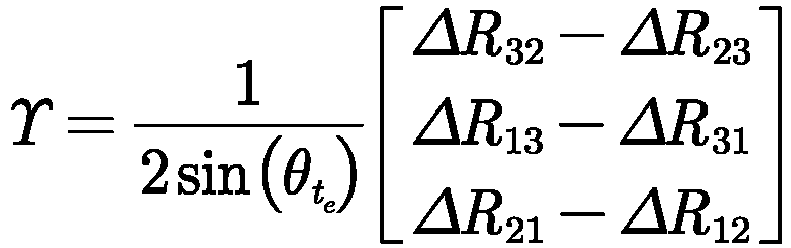
s , Rte , and ΔR is a matrix of 3 rows and 3 columns; ΔRij is an element in the i th row and the j th column in the gesture change ΔR , and a value of i is 1, 2, or 3; a value of j is 1, 2, or 3; sin(•) is used for representing a sine function; cos(•) is used for representing a cosine function. - According to a curve interpolation method, curve difference calculation is performed on the rotation angle θ, to obtain relational data θ(t) between the rotation angle θ and the interval duration t, so that the relational data θ(t) meets the following relation:

e represents that the rotation angle of the legged robot at the end time point is θte , and the θte is a constant; θ̇(te ) = 0 represents that the angular speed of the legged robot at the end time point is 0. - Through the relational data θ(t) , relational data R(t) between the gesture of the legged robot and the interval duration t is created, and the relational data R(t) meets the following relation:

s represents the gesture of the legged robot at the start time point. - Through the relational data R(t), relational data between a change amount of the angular momentum corresponding to the legged robot and the interval duration t is created. The relational data between the change amount of the angular momentum corresponding to the legged robot and the interval duration t meets the following relation:


- Then, the relational data between the acting force to which the at least one leg of the legged robot is subjected and the position of center of mass P(t) of the legged robot is converted, and the converted relational data between the acting force to which the at least one leg of the legged robot is subjected and the position of center of mass P(t) of the legged robot meets the following relation:


 represents a real number set in a multi-dimensional space; f 0 is used for representing a sum of acting forces to which at least one leg in contact with the ground of the legged robot is subjected; H 0 is a constant matrix; Wg is a constant vector;


- The first relational data and the relational data between the acceleration of center of mass P̈(t) corresponding to the position of center of mass P(t) and the interval duration t are substituted into the foregoing converted relational data between the acting force to which the at least one leg of the legged robot is subjected and the position of center of mass P(t) of the legged robot, to obtain second relational data, and the second relational data meets the following relation:


- Third. Process of creating third relational data:
- The third relational data is created based on a friction force constraint to which the legged robot is subjected, the fourth relational data, and the first relational data.
- In a movement process of the legged robot, the legged robot is subjected to a friction force constraint: a leg in contact with the ground of the legged robot is subjected to a friction force greater than 0, and the friction force to which the leg is subjected is not less than a component force of an acting force fi to which the leg in contact with the ground is subjected in a friction force direction, to avoid generating relative slide between the leg and the ground, thereby ensuring that the legged robot can normally move. An acting force fi corresponding to each of at least one leg of the legged robot is subjected to a friction force constraint, and the following relationship is met:
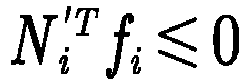


 represents a real number set in a multi-dimensional space; 0 i and t i represent two tangent vectors on a plane perpendicular to the normal vector of the contact point in contact with the ground of the i th leg of the legged robot, the tangent vector 0 i and the tangent vector t i are orthogonal with each other, and 0i ,
- In a movement process of the legged robot, the legged robot is subjected to a friction force constraint. Therefore, a direction of the acting force to which the i th leg in contact with the ground of the legged robot is subjected is within a cone, a contact point in contact with the ground of the i th leg is a vertex of the cone, and a connecting line within the cone from the vertex to any point of a base circle of the cone can be used as the direction of the acting force fi to which the i th leg in contact with the ground is subjected. To avoid introducing a nonlinear constraint, the cone is approximately presented as a rectangular pyramid, and the acting force fi to which the i th leg in contact with the ground meets the following relation:

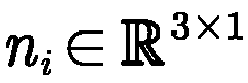 represents a real number set in a multi-dimensional space; 0i and ti represent two tangent vectors on a plane perpendicular to the normal vector of the contact point in contact with the ground of the i th leg of the legged robot, the tangent vector 0i and the tangent vector ti are orthogonal with each other, and 0i,


- In the foregoing relation, through a constraint on component forces of the acting force fi to which the i th leg in contact with the ground of the legged robot is subjected on the four side surfaces of the rectangular pyramid, and a constraint on component forces of the acting force fi to which the i th leg in contact with the ground of the legged robot is subjected in the normal direction, the direction of the acting force fi to which the i th leg in contact with the ground of the legged robot is subjected is limited within the rectangular pyramid.
- When a legged robot is in any position in a movement process, friction force constraints to which acting forces corresponding to all legs of the legged robot are subjected meet the following relation:


- k sampling time points (t 1 , t 2 ,..., tk) are selected within the target movement duration, and G, f, N, H, and Wg of the legged robot at the sampling time point tk are respectively represented as Gk, fk, Nk, Hk , and Wgk. Moreover, when the legged robot is at the sampling time point tk , the acting force fi, to which the at least one leg in contact with the ground of the legged robot is subjected meets the following relation:


- Gk, fk , Nk , Hk , and Wgk are related to a situation that at least one leg of the legged robot is in contact with the ground when the legged robot is at the sampling time point tk . For example, the legged robot is configured with 4 legs, which are respectively a right rear leg, a right front leg, a left rear leg, and a left front leg, and a stepping sequence of the legged robot is stepping with the right rear leg, stepping with the right front leg, stepping with the left rear leg, and stepping with the left front leg. Optionally, each half stepping period is stepping with the right rear leg and stepping with the right front leg, or stepping with the left rear leg and stepping with the left front leg. The legged robot repeatedly performs the stepping process of the plurality of legs according to the stepping sequence, thereby enabling the legged robot to move. The movement process of the legged robot includes eight movement stages: supporting with four legs, stepping with the right rear leg, stepping with the right front leg, supporting with four legs, supporting with four legs, stepping with the left rear leg, and stepping with the left front leg. When the legged robot is in a state of supporting with four legs, Gk is a 6×12 matrix, fk is a 12×1 column vector, and Nk is a 16×12 matrix. When the robot is in a different stage, the quantity of footholds, the position, and other related information may change.
- The second relational data created through the fourth relational data and the first relational data meets the following relation:

- After the second relational data is created, assuming that the start time point t is 0 when the legged robot is in the initiation position, based on the selected B sampling time points, the value of the constant C at which the target value J has the minimum value is determined according to the following relation:

- The method for determining the position of center of mass provided in this embodiment of this application is applicable to various legged robots, for example, a two-legged robot, a four-legged robot or a six-legged robot; is applicable to various gaits of the legged robot, for example, two-legged walking, four-legged diagonal gait, four-legged crawling gait, and six-legged diagonal gait; is applicable to various complex environments, for example, a flat ground, an uneven ground, a slope, or stairs; can use any order of the interval duration t, and can use any movement process in the process from the initiation position to the termination position; and can keep, in a case that the ground is a plane or has a relatively small height difference, the height of the center of mass of the robot unchanged, and use only 2 groups of curves to plan movement of the center of mass in the plane. Continuity constraints such as curve position, speed, acceleration may be added according to actual requirements, and it is necessary to ensure that a curve parameter having a constraint added still has an independent variable. When sampling time points are selected, sampling can be performed in any position on the trajectory of the position of center of mass, and a larger quantity of sampling time points indicates more proper distribution, and a more reliable movement trajectory of the center of mass obtained, but a larger dimension and a longer solving time of the quadratic programming problem. Additionally, in the second relational data, the acting force to which the at least one leg in contact with the ground of the legged robot is subjected, and the distance corresponding to the sampling time point both have components in three directions of the x axis, the y axis, and the z axis, and different weights can be respectively selected on the x axis, the y axis, and the z axis according to an actual situation, to determine a weighted sum of squares of acting forces, and a weighted sum of squares of distances. Additionally, in the second relational data, in addition to the acting force of the ground and the curve oscillation amplitude, a sum of squares of accelerations, a sum of squares of speed differences between neighboring points, a sum of squares of differences between accelerations, and the like can be further considered. Position of a contact point: the contact point is not merely limited to a contact point in contact with the ground on a leg of the legged robot, and is similarly applicable to a case that a part of the robot such as the body, the trunk, or the upper limb is in contact with an environment. Based on the method for determining the position of center of mass provided in this embodiment of this application, in a case that a term with a relatively small effect is ignored, the position of center of mass constraint, the speed of center of mass constraint, the acceleration of center of mass constraint, and the ground friction force constraint are fully considered, the trajectory of center of mass programming problem is converted in to a quadratic programming problem, and a trajectory of center of mass of movement of the legged robot is determined by using the quadratic programming problem. in the quadratic programming problem, the friction force constraint of the contact point on the ground and various optimization indexes are fully considered, to ensure feasibility and efficiency of the generated movement.
-
FIG. 13 is a schematic structural diagram of an apparatus for determining a position of center of mass according to an embodiment of this application. As shown inFIG. 13 , the apparatus includes: - a creating
module 1301, configured to create first relational data, the first relational data indicating a relationship between an interval duration t and a position of center of mass P(t) of a legged robot, and the first relational data including a first constant C ; - the creating
module 1301 being further configured to create second relational data corresponding to at least one leg configured for the legged robot, the second relational data corresponding to the at least one leg separately indicating a relationship between an acting force fi corresponding to the at least one leg and the position of center of mass P(t) , and the second relational data including the first constant C ; - the creating
module 1301 being further configured to create third relational data based on the second relational data corresponding to the at least one leg, and determining a value of the first constant C at which a target value J has a minimum value, the third relational data indicating a positive correlation between the target value J and a square of an acting force fi to which the at least one leg in contact with the ground is subjected; and - an obtaining
module 1302, configured to obtain the first relational data corresponding to the first constant C whose value is determined. - In a possible implementation, as shown in
FIG. 14 , the creatingmodule 1301 includes: - a first creating
unit 1311, configured to create the third relational data based on the first relational data and the second relational data corresponding to the at least one leg; and - a first determining
unit 1312, configured to determine, based on the third relational data, the value of the first constant C at which the target value J has the minimum value. - In another possible implementation, as shown in
FIG. 14 , the creatingmodule 1301 includes: - a first obtaining
unit 1313, configured to obtain first state data and second state data of the legged robot in an initiation position and a termination position respectively, where the state data includes at least positions of center of mass, speeds of center of mass, and accelerations of center of mass; and - the first creating
unit 1311 is further configured to create the first relational data, where the first relational data includes the first constant C , the first constant C includes a second constant Cfree whose value is not determined and a third constant h whose value is determined, and the third constant h is determined based on the obtained state data. - In another possible implementation, as shown in
FIG. 14 , the creatingmodule 1301 includes: - a
setting unit 1314, configured to set the first relational data as follows: the position of center of mass P(t) is a product of the first constant C and a duration matrix E ; and
- where Et represents a duration vector.
- In another possible implementation, as shown in
FIG. 14 , the creatingmodule 1301 includes:
asetting unit 1314, configured to set second relational data corresponding to at least one leg as follows: an acting force fi corresponding to an i th leg is a sum of a linear mapping of a fourth constant A corresponding to the i th leg and the first constant C . - In another possible implementation, as shown in
FIG. 14 , the first creatingunit 1311 includes: - an obtaining subunit 13111, configured to obtain a movement duration required for the legged robot to move from an initiation position to a termination position;
- a selecting
subunit 13112, configured to select a plurality of sampling time points within the movement duration; - a determining
subunit 13113, configured to determine, based on an interval duration between each sampling time point and a start time point and the first relational data, fourth relational data corresponding to the each sampling time point, where the fourth relational data indicates a relationship between the first constant C and a sampling position of center of mass Q(C), and the sampling position of center of mass Q(C) indicates a position of center of mass of the legged robot at the corresponding sampling time point; - the determining
subunit 13113 being further configured to determine, based on the second relational data corresponding to the at least one leg and the fourth relational data, fifth relational data corresponding to the each sampling time point, where the fifth relational data indicates a relationship between the first constant C and the acting force fi corresponding to the at least one leg; and - a creating
subunit 13114, configured to create the third relational data based on the fourth relational data and the fifth relational data, where the third relational data further indicates a positive correlation between the target value J and a square of the acting force fi corresponding to the at least one leg corresponding to the each sampling time point and the sampling position of center of mass Q(C). - In another possible implementation, the creating
subunit 13114 is configured to set the target value J to a sum value of a weighted sum of squares of a plurality of distances and a weighted sum of squares of the acting force fi corresponding to the at least one leg, where the plurality of distances include a distance between any two neighboring positions of center of mass of, a position of center of mass in the initiation position, a plurality of sampling positions of center of mass, and a position of center of mass in the termination position. - In another possible implementation, the determining
subunit 13113 is configured to determine, based on a stepping sequence of the legged robot, a stepping duration corresponding to the at least one leg, and the interval duration between the each sampling time point and the start time point, a leg of the legged robot in contact with the ground at the each sampling time point, where the stepping sequence indicates a stepping sequence of a plurality of legs of the legged robot, and a stepping duration corresponding to the leg is a duration from lifting to putting down of the leg; and determining the fifth relational data based on each sampling position of center of mass Q(C) , the second relational data corresponding to the at least one leg, and the leg in contact with the ground at the each sampling time point. - In another possible implementation, as shown in
FIG. 14 , the apparatus further includes: - the obtaining
module 1302 is further configured to obtain second state data of the legged robot in a termination position; - a determining
module 1303, configured to determine, based on a target movement duration and the first relational data, prediction state data of the legged robot in the termination position; and - the creating
module 1301 includes:- a first creating
unit 1311, configured to create the third relational data based on a state data error between the second state data and the prediction state data, where the third relational data indicates a positive correlation between the target value J and the state data error and the square of the acting force fi to which the at least one leg in contact with the ground is subjected; and - a first determining
unit 1312, configured to determine, based on the second relational data and the third relational data, the value of the first constant C at which the target value J has the minimum value.
- a first creating
- In another possible implementation, the second state data includes a target position of center of mass, and the prediction state data includes a prediction position of center of mass; and as shown in
FIG. 14 , the first creatingunit 1311 includes: - a determining
subunit 13113, configured to determine a first difference between the target position of center of mass and the prediction position of center of mass; and - a setting
subunit 13115, configured to set the target value J to a sum value of a weighted sum of squares of the acting force fi corresponding to the at least one leg, and a square of the first difference. - In another possible implementation, the second state data includes a target acceleration of center of mass, and the prediction state data includes a prediction acceleration of center of mass; and as shown in
FIG. 14 , the first creatingunit 1311 includes: - a determining
subunit 13113, configured to determine a second difference between the target acceleration of center of mass and the prediction acceleration of center of mass; and - a setting
subunit 13115, configured to set the target value J to a sum value of a weighted sum of squares of the acting force fi corresponding to the at least one leg, and a square of the second difference. - In another possible implementation, the second state data includes a target speed of center of mass, and the prediction state data includes a prediction speed of center of mass; and as shown in
FIG. 14 , the first creatingunit 1311 includes: - a determining
subunit 13113, configured to determine a third difference between the target speed of center of mass and the prediction speed of center of mass; and - a setting
subunit 13115, configured to set the target value J to a sum value of a weighted sum of squares of the acting force fi corresponding to the at least one leg, and a square of the third difference. - In another possible implementation, as shown in
FIG. 14 , the first creatingunit 1311 includes: - a selecting
subunit 13112, configured to select a plurality of sampling time points within the target movement duration; - a determining
subunit 13113, configured to determine, based on an interval duration between each sampling time point and a start time point and the first relational data, fourth relational data corresponding to the each sampling time point, where the fourth relational data indicates a relationship between the first constant C and a sampling position of center of mass Q(C); and - a creating
subunit 13114, configured to create the third relational data based on the state data error and the fourth relational data, where the third relational data indicates a positive correlation between the target value J and a square of the acting force fi corresponding to the at least one leg corresponding to the each sampling time point, the state data error, and the sampling position of center of mass Q(C). - In another possible implementation, the second state data includes a target position of center of mass, and the prediction state data includes a prediction position of center of mass; and the creating
subunit 13114 is configured to determine a first difference between the target position of center of mass and the prediction position of center of mass; and set the target value J to a sum value of a first value, a second value, and a third value, where the first value is a square of the first difference, the second value is a weighted sum of squares of a plurality of distances, the plurality of distances include a distance between any two neighboring positions of center of mass of a position of center of mass in an initiation position, a plurality of sampling positions of center of mass, and the prediction position of center of mass, and the third value is a weighted sum of squares of the acting force fi corresponding to the at least one leg corresponding to the each sampling time point. - In another possible implementation, the second state data includes a target acceleration of center of mass, and the prediction state data includes a prediction acceleration of center of mass; and the creating
subunit 13114 is configured to determine a second difference between the target acceleration of center of mass and the prediction acceleration of center of mass; and set the target value J to a sum value of a second value, a third value, and a fourth value, where the fourth value is a square of the second difference, the second value is a weighted sum of squares of a plurality of distances, the plurality of distances include a distance between any two neighboring positions of center of mass of an initiation position of center of mass in an initiation position, a plurality of sampling positions of center of mass, and the prediction position of center of mass, and the third value is a weighted sum of squares of the acting force fi corresponding to the at least one leg corresponding to the each sampling time point. - In another possible implementation, the second state data includes a target speed of center of mass, and the prediction state data includes a prediction speed of center of mass; and the creating
subunit 13114 is configured to determine a third difference between the target speed of center of mass and the prediction speed of center of mass; and set the target value J to a sum value of a second value, a third value, and a fifth value, where the fifth value is a square of the third difference, the second value is a weighted sum of squares of a plurality of distances, the plurality of distances include a distance between any two neighboring positions of center of mass of an initiation position of center of mass in an initiation position, a plurality of sampling positions of center of mass, and the prediction position of center of mass, and the third value is a weighted sum of squares of the acting force fi corresponding to the at least one leg corresponding to the each sampling time point. - In another possible implementation,
- the first creating
unit 1311 is further configured to create sixth relational data, where the sixth relational data indicates a relationship between an angular momentum L of the legged robot and the interval duration t ; - the first creating
unit 1311 is further configured to create seventh relational data, where the seventh relational data indicates a negative correlation between the acting force fi (L) corresponding to the at least one leg and the angular momentum L ; and - the first creating
unit 1311 is further configured to create, based on the sixth relational data and the seventh relational data, the second relational data corresponding to the at least one leg. - In another possible implementation, the first determining
unit 1312 is configured to create eighth relational data, ninth relational data, and tenth relational data based on the first relational data and a start time point, where the eighth relational data indicates a relationship between an initiation position of center of mass of the legged robot in an initiation position and the first constant C, the ninth relational data indicates a relationship between an initiation speed of center of mass of the legged robot in the initiation position and the first constant C , and the tenth relational data indicates a relationship between an initiation acceleration of center of mass of the legged robot in the initiation position and the first constant C; and determine, based on the eighth relational data, the ninth relational data, the tenth relational data, the second relational data, and the third relational data, the value of the first constant C at which the target value J has the minimum value. - In another possible implementation, the second state data includes a target position of center of mass, and as shown in
FIG. 14 , the obtainingmodule 1302 includes: - a second obtaining
unit 1321, configured to obtain, in a case that the legged robot is in the termination position, a position of a contact point in contact with the ground of the at least one leg configured for the legged robot; and - a second determining
unit 1322, configured to determine the target position of center of mass based on the position of the contact point of the at least one leg. - In another possible implementation, the second state data further includes a target speed of center of mass, and
- the obtaining
module 1302 is further configured to obtain first state data of the legged robot in an initiation position, where the first state data includes at least an initiation position of center of mass; and - the determining
module 1303 is further configured to determine a ratio of a distance between the target position of center of mass and the initiation position of center of mass to the target movement duration as the target speed of center of mass. - In another possible implementation, the second state data further includes a target acceleration of center of mass, and the first state data further includes an initiation speed of center of mass; and
the determiningmodule 1303 is further configured to determine a ratio of a difference between the target speed of center of mass and the initiation speed of center of mass to the target movement duration as the target acceleration. - In another possible implementation, the prediction state data includes a prediction position of center of mass, and as shown in
FIG. 14 , the determiningmodule 1303 includes:
a third determiningunit 1331, configured to determine, based on the first relational data, the prediction position of center of mass of the legged robot after the target movement duration elapses from an initiation position. - In another possible implementation, the prediction state data includes a prediction speed of center of mass, and as shown in
FIG. 14 , the determiningmodule 1303 includes: - a second creating
unit 1332, configured to create, based on the first relational data, relational data between the interval duration t and a speed of center of mass of the legged robot; and - a third determining
unit 1331, configured to determine, based on the relational data between the interval duration t and the speed of center of mass of the legged robot, the prediction speed of center of mass of the legged robot after the target movement duration elapses from an initiation position. - In another possible implementation, the prediction state data includes a prediction acceleration of center of mass, and as shown in
FIG. 14 , the determiningmodule 1303 includes: - a second creating
unit 1332, configured to create, based on the first relational data, relational data between the interval duration t and an acceleration of center of mass of the legged robot; and - a third determining
unit 1331, configured to determine, based on the relational data between the interval duration t and the acceleration of center of mass of the legged robot, the prediction acceleration of center of mass of the legged robot after the target movement duration elapses from an initiation position. - In another possible implementation, after the first relational data corresponding to the first constant C whose value is determined is obtained, as shown in
FIG. 14 , the apparatus further includes: - a determining
module 1303, configured to determine, based on the first relational data, a position of center of mass P(t 0 ) of the legged robot within any interval duration t 0 in a movement process of the legged robot; - the determining
module 1303 being further configured to determine, based on the position of center of mass P(t 0 ) and the termination position, joint torques of a plurality of joints of the legged robot; and - a
control module 1304, configured to control, according to the joint torques of the plurality of joints, the plurality of joints to rotate, to drive the legged robot to move. - When the apparatus for determining the position of center of mass provided in the foregoing embodiment obtains the first relational data, it is illustrated with an example of division of functional modules. During practical application, the function distribution may be implemented by different functional modules according to requirements, that is, an internal structure of the legged robot or control device is divided into different functional modules, to implement all or some of the functions described above. In addition, embodiments of the apparatus for determining the position of center of mass and the method for determining the position of center of mass provided in the foregoing embodiments belong to the same conception. For the specific implementation process, reference may be made to the method embodiments, and details are not described herein again.
- An embodiment of this application further provides a legged robot, including: a processor and a memory, the memory storing at least one computer program, and the at least one computer program being loaded and executed by the processor to implement operations performed in the method for determining the position of center of mass according to the foregoing embodiments.
-
FIG. 15 is a schematic structural diagram of alegged robot 1500 according to an exemplary embodiment of this application. Thelegged robot 1500 is configured to perform steps performed by the legged robot in the foregoing method for determining the position of center of mass. - The
legged robot 1500 includes aprocessor 1501 and amemory 1502. - The
processor 1501 may include one or more processing cores, for example, a 4-core processor or a 15-core processor. Thememory 1502 may include one or more computer-readable storage media. The computer-readable storage medium may be non-transient and is configured to store at least one computer program, the at least one computer program being configured to be executed by theprocessor 1501 to implement the method for determining the position of center of mass provided in the method embodiments of this application. - In some embodiments, the
legged robot 1500 optionally includes: aperipheral interface 1503 and at least one peripheral. Theprocessor 1501, thememory 1502, and theperipheral interface 1503 may be connected through a bus or a signal cable. Each peripheral may be connected to theperipheral interface 1503 through a bus, a signal cable, or a circuit board. Optionally, the peripheral includes at least one of a radio frequency (RF)circuit 1504, adisplay screen 1505, acamera component 1505, anaudio circuit 1507, apositioning component 1506, and apower supply 1507. - The
peripheral interface 1503 may be configured to connect the at least one peripheral related to input/output (I/O) to theprocessor 1501 and thememory 1502. - The
RF circuit 1504 is configured to receive and transmit an RF signal, also referred to as an electromagnetic signal. TheRF circuit 1504 communicates with a communication network and other communication devices through the electromagnetic signal. - The
camera component 1505 is configured to capture images or videos. Optionally, thecamera component 1505 includes a front-facing camera and a rear-facing camera. The front-facing camera is disposed on the front panel of the terminal, and the rear-facing camera is disposed on a back face of the terminal. - The
positioning component 1506 is configured to determine a current geographic location of thelegged robot 1500, to implement a navigation or a location based service (LBS). Thepositioning component 1506 may be a positioning component based on the global positioning system (GPS) of the United States, the BeiDou System of China, and the GALILEO System of Russia. - The
power supply 1507 is configured to supply power to components in thelegged robot 1500. Thepower supply 1507 may be an alternating current, a direct current, a disposable battery, or a rechargeable battery. When thepower supply 1507 includes a rechargeable battery, and the rechargeable battery may be a wired rechargeable battery or a wireless rechargeable battery. The wired rechargeable battery is a battery charged through a wired circuit, and the wireless rechargeable battery is a battery charged through a wireless coil. The rechargeable battery may be further configured to support a fast charging technology. - In some embodiments, the
legged robot 1500 further includes one ormore sensors 1508. The one ormore sensors 1508 include, but are not limited to: anacceleration sensor 1509 and agyroscope sensor 1510. - The
acceleration sensor 1509 may detect accelerations on three coordinate axes of a coordinate system established by thelegged robot 1500. For example, theacceleration sensor 1509 may be configured to detect components of the gravity acceleration on the three coordinate axes. Theprocessor 1501 may control, according to a gravity acceleration signal collected by theacceleration sensor 1509. Theacceleration sensor 1509 may be further configured to acquire game or user movement data. - The
gyroscope sensor 1510 may detect a body direction and a rotation angle of thelegged robot 1500. Thegyroscope sensor 1510 may acquire a 3D action of the user on thelegged robot 1500 together with theacceleration sensor 1509. Theprocessor 1501 may implement the following functions according to the data collected by the gyroscope sensor 1510: movement sensing (such as changing the UI according to a tilt operation of the user), image stabilization during shooting, game control, and inertial navigation. - A person skilled in the art may understand that the structure shown in
FIG. 15 does not constitute a limitation on thelegged robot 1500, and the terminal may include more or fewer components than those shown in the figure, or some components may be combined, or a different component deployment may be used. - An embodiment of this application further provides a control device, including: a processor and a memory, the memory storing at least one computer program, and the at least one computer program being loaded and executed by the processor to implement operations performed in the method for determining the position of center of mass according to the foregoing embodiments.
- Optionally, the computer device is provided as a server.
FIG. 16 is a schematic structural diagram of a server according to an embodiment of this application. Theserver 1600 may vary greatly due to different configurations or performance, and may include one or more processors (such as CPUs) 1601 and one ormore memories 1602. Thememory 1602 stores at least one computer program, the at least one computer program being loaded and executed by theprocessor 1601 to implement the methods provided in the foregoing method embodiments. Certainly, the server may also have a wired or wireless network interface, a keyboard, an input/output interface and other components to facilitate input/output. The server may also include other components for implementing device functions. Details are not described herein again. - An embodiment of this application further provides a computer-readable storage medium. The computer-readable storage medium stores at least one computer program, the at least one computer program being loaded and executed by a processor to implement operations performed in the method for determining the position of center of mass according to the foregoing embodiments.
- An embodiment of this application further provides a computer program product or a computer program. The computer program product or the computer program stores computer program code, the computer program code being stored in a computer-readable storage medium. A processor of a control device reads the computer program code from the computer-readable storage medium, and the processor executes the computer program code, to cause the control device to implement operations performed in the method for determining the position of center of mass according to the foregoing embodiments.
- A person of ordinary skill in the art may understand that all or some of the steps of the foregoing embodiments may be implemented by hardware, or may be implemented a program instructing related hardware. The program may be stored in a computer-readable storage medium. The storage medium may be: a ROM, a magnetic disk, or an optical disc.
- The foregoing descriptions are merely optional embodiments of the embodiments of this application, but are not intended to limit the embodiments of this application. Any modification, equivalent replacement, or improvement made within the spirit and principle of the embodiments of this application shall fall within the protection scope of this application.
Claims (29)
- A method for determining a position of center of mass, applied to a legged robot or a control device connected to the legged robot, the method comprising:creating first relational data, the first relational data indicating a relationship between an interval duration t and a position of center of mass P(t) of the legged robot, and the first relational data comprising a first constant C ;creating second relational data corresponding to at least one leg configured for the legged robot, the second relational data corresponding to the at least one leg separately indicating a relationship between an acting force fi corresponding to the at least one leg and the position of center of mass P(t) , and the second relational data comprising the first constant C ;creating third relational data based on the second relational data corresponding to the at least one leg, and determining a value of the first constant C at which a target value J has a minimum value, the third relational data indicating a positive correlation between the target value J and a square of the acting force fi to which the at least one leg in contact with the ground is subjected; andobtaining the first relational data corresponding to the first constant C whose value is determined.
- The method according to claim 1, wherein creating the third relational data based on the second relational data corresponding to the at least one leg, and determining the value of the first constant C at which the target value J has the minimum value comprises:creating the third relational data based on the first relational data and the second relational data corresponding to the at least one leg; anddetermining, based on the third relational data, the value of the first constant C at which the target value J has the minimum value.
- The method according to claim 2, wherein creating the first relational data comprises:obtaining first state data and second state data of the legged robot in an initiation position and a termination position respectively, wherein the state data comprises at least positions of center of mass, speeds of center of mass, and accelerations of center of mass; andcreating the first relational data, wherein the first relational data comprises the first constant C , the first constant C comprises a second constant Cfree whose value is not determined and a third constant h whose value is determined, and the third constant h is determined based on the obtained state data.
- The method according to claim 2, wherein creating the first relational data comprises:setting the first relational data as follows: the position of center of mass P(t) is a product of the first constant C and a duration matrix E ; and
 wherein Et represents a duration vector.
 - The method according to claim 2, wherein creating the second relational data corresponding to at least one leg configured for the legged robot comprises:
setting the second relational data corresponding to the at least one leg as follows: an acting force fi corresponding to an i th leg is a sum of a linear mapping of a fourth constant A corresponding to the i th leg and the first constant C . - The method according to claim 2, wherein creating the third relational data based on the first relational data and the second relational data corresponding to the at least one leg comprises:obtaining a movement duration required for the legged robot to move from an initiation position to a termination position;selecting a plurality of sampling time points within the movement duration;determining, based on the first relational data and an interval duration between each sampling time point and a start time point, fourth relational data corresponding to each sampling time point, wherein the fourth relational data indicates a relationship between the first constant C and a sampling position of center of mass Q(C) , and the sampling position of center of mass Q(C) indicates a position of center of mass of the legged robot at the corresponding sampling time point;determining, based on the second relational data corresponding to the at least one leg and the fourth relational data, fifth relational data corresponding to each sampling time point, wherein the fifth relational data indicates a relationship between the first constant C and the acting force fi corresponding to the at least one leg; andcreating the third relational data based on the fourth relational data and the fifth relational data, wherein the third relational data further indicates a positive correlation between the target value J and a square of the acting force fi corresponding to the at least one leg at each sampling time point and the sampling position of center of mass Q(C).
- The method according to claim 6, wherein creating the third relational data based on the fourth relational data and the fifth relational data comprises:
setting the target value J to a sum value of a weighted sum of squares of a plurality of distances and a weighted sum of squares of the acting force fi corresponding to the at least one leg, wherein the plurality of distances comprise a distance between any two neighboring positions of center of mass of, a position of center of mass in the initiation position, a plurality of sampling positions of center of mass, and a position of center of mass in the termination position. - The method according to claim 6, wherein determining, based on the second relational data corresponding to the at least one leg and the fourth relational data, the fifth relational data corresponding to each sampling time point comprises:determining, based on a stepping sequence of the legged robot, a stepping duration corresponding to the at least one leg, and the interval duration between each sampling time point and the start time point, a leg of the legged robot in contact with the ground at each sampling time point, wherein the stepping sequence indicates a stepping sequence of a plurality of legs of the legged robot, and a stepping duration corresponding to the leg is a duration from lifting to putting down of the leg; anddetermining the fifth relational data based on each sampling position of center of mass Q(C), the second relational data corresponding to the at least one leg, and the leg in contact with the ground at each sampling time point.
- The method according to claim 1, further comprising:obtaining second state data of the legged robot in a termination position; anddetermining, based on a target movement duration and the first relational data, prediction state data of the legged robot in the termination position;creating the third relational data based on the second relational data corresponding to the at least one leg, and determining the value of the first constant C at which the target value J has the minimum value comprises:creating the third relational data based on a state data error between the second state data and the prediction state data, wherein the third relational data indicates a positive correlation between the target value J and the state data error and the square of the acting force fi to which the at least one leg in contact with the ground is subjected; anddetermining, based on the second relational data and the third relational data, the value of the first constant C at which the target value J has the minimum value.
- The method according to claim 9, wherein the second state data comprises a target position of center of mass, and the prediction state data comprises a prediction position of center of mass; and creating the third relational data based on the state data error between the second state data and the prediction state data comprises:determining a first difference between the target position of center of mass and the prediction position of center of mass; andsetting the target value J to a sum value of a weighted sum of squares of the acting force fi corresponding to the at least one leg, and a square of the first difference.
- The method according to claim 9, wherein the second state data comprises a target acceleration of center of mass, and the prediction state data comprises a prediction acceleration of center of mass; and creating the third relational data based on the state data error between the second state data and the prediction state data comprises:determining a second difference between the target acceleration of center of mass and the prediction acceleration of center of mass; andsetting the target value J to a sum value of a weighted sum of squares of the acting force fi corresponding to the at least one leg, and a square of the second difference.
- The method according to claim 9, wherein the second state data comprises a target speed of center of mass, and the prediction state data comprises a prediction speed of center of mass; and creating the third relational data based on the state data error between the second state data and the prediction state data comprises:determining a third difference between the target speed of center of mass and the prediction speed of center of mass; andsetting the target value J to a sum value of a weighted sum of squares of the acting force fi corresponding to the at least one leg, and a square of the third difference.
- The method according to claim 9, wherein creating the third relational data based on the state data error between the second state data and the prediction state data comprises:selecting a plurality of sampling time points within the target movement duration;determining, based on the first relational data and an interval duration between each sampling time point and a start time point, fourth relational data corresponding to each sampling time point, wherein the fourth relational data indicates a relationship between the first constant C and a sampling position of center of mass Q(C) ;creating the third relational data based on the state data error and the fourth relational data, wherein the third relational data indicates a positive correlation between the target value J and a square of the acting force fi corresponding to the at least one leg at each sampling time point, the state data error, and the sampling position of center of mass Q(C).
- The method according to claim 13, wherein the second state data comprises a target position of center of mass, and the prediction state data comprises a prediction position of center of mass; and creating the third relational data based on the state data error and the fourth relational data comprises:determining a first difference between the target position of center of mass and the prediction position of center of mass; andsetting the target value J to a sum value of a first value, a second value, and a third value, wherein the first value is a square of the first difference, the second value is a weighted sum of squares of a plurality of distances, the plurality of distances comprise a distance between any two neighboring positions of center of mass of, a position of center of mass in an initiation position, a plurality of sampling positions of center of mass, and the prediction position of center of mass, and the third value is a weighted sum of squares of the acting force fi corresponding to the at least one leg at each sampling time point.
- The method according to claim 13, wherein the second state data comprises a target acceleration of center of mass, and the prediction state data comprises a prediction acceleration of center of mass; and creating the third relational data based on the state data error and the fourth relational data comprises:determining a second difference between the target acceleration of center of mass and the prediction acceleration of center of mass; andsetting the target value J to a sum value of a second value, a third value, and a fourth value, wherein the fourth value is a square of the second difference, the second value is a weighted sum of squares of a plurality of distances, the plurality of distances comprise a distance between any two neighboring positions of center of mass of, an initiation position of center of mass in an initiation position, a plurality of sampling positions of center of mass, and the prediction position of center of mass, and the third value is a weighted sum of squares of the acting force fi corresponding to the at least one leg at each sampling time point.
- The method according to claim 13, wherein the second state data comprises a target speed of center of mass, and the prediction state data comprises a prediction speed of center of mass; and creating the third relational data based on the state data error and the fourth relational data comprises:determining a third difference between the target speed of center of mass and the prediction speed of center of mass; andsetting the target value J to a sum value of a second value, a third value, and a fifth value, wherein the fifth value is a square of the third difference, the second value is a weighted sum of squares of a plurality of distances, the plurality of distances comprise a distance between any two neighboring positions of center of mass of, an initiation position of center of mass in an initiation position, a plurality of sampling positions of center of mass, and the prediction position of center of mass, and the third value is a weighted sum of squares of the acting force fi corresponding to the at least one leg at each sampling time point.
- The method according to claim 9, wherein creating the second relational data corresponding to the at least one leg configured for the legged robot comprises:creating sixth relational data, wherein the sixth relational data indicates a relationship between an angular momentum L of the legged robot and the interval duration t ;creating seventh relational data, wherein the seventh relational data indicates a negative correlation between the acting force fi (L) corresponding to the at least one leg and the angular momentum L ; andcreating, based on the sixth relational data and the seventh relational data, the second relational data corresponding to the at least one leg.
- The method according to claim 9, wherein determining, based on the second relational data and the third relational data, the value of the first constant C at which the target value J has the minimum value comprises:creating eighth relational data, ninth relational data, and tenth relational data based on the first relational data and a start time point, wherein the eighth relational data indicates a relationship between an initiation position of center of mass of the legged robot in an initiation position and the first constant C , the ninth relational data indicates a relationship between an initiation speed of center of mass of the legged robot in the initiation position and the first constant C , and the tenth relational data indicates a relationship between an initiation acceleration of center of mass of the legged robot in the initiation position and the first constant C; anddetermining, based on the eighth relational data, the ninth relational data, the tenth relational data, the second relational data, and the third relational data, the value of the first constant C at which the target value J has the minimum value.
- The method according to claim 9, wherein the second state data comprises a target position of center of mass, and obtaining the second state data of the legged robot in the termination position comprises:obtaining a position of a contact point in contact with the ground of the at least one leg configured for the legged robot when the legged robot is in the termination position; anddetermining the target position of center of mass based on the position of the contact point of the at least one leg.
- The method according to claim 19, wherein the second state data further comprises a target speed of center of mass, and the method further comprises:obtaining first state data of the legged robot in the initiation position, wherein the first state data comprises at least an initiation position of center of mass; anddetermining a ratio of a distance between the target position of center of mass and the initiation position of center of mass to the target movement duration as the target speed of center of mass.
- The method according to claim 20, wherein the second state data further comprises a target acceleration of center of mass, and the first state data further comprises an initiation speed of center of mass; and the method further comprises:
determining a ratio of a difference between the target speed of center of mass and the initiation speed of center of mass to the target movement duration as the target acceleration. - The method according to claim 9, wherein the prediction state data comprises a prediction position of center of mass, and determining, based on the target movement duration and the first relational data, the prediction state data of the legged robot in the termination position comprises:
determining, based on the first relational data, the prediction position of center of mass of the legged robot after the target movement duration elapses from an initiation position. - The method according to claim 9, wherein the prediction state data comprises a prediction speed of center of mass, and determining, based on the target movement duration and the first relational data, the prediction state data of the legged robot in the termination position comprises:creating, based on the first relational data, relational data between the interval duration t and a speed of center of mass of the legged robot; anddetermining, based on the relational data between the interval duration t and the speed of center of mass of the legged robot, the prediction speed of center of mass of the legged robot after the target movement duration elapses from an initiation position.
- The method according to claim 9, wherein the prediction state data comprises a prediction acceleration of center of mass, and determining, based on the target movement duration and the first relational data, the prediction state data of the legged robot in the termination position comprises:creating, based on the first relational data, relational data between the interval duration t and an acceleration of center of mass of the legged robot; anddetermining, based on the relational data between the interval duration t and the acceleration of center of mass of the legged robot, the prediction acceleration of center of mass of the legged robot after the target movement duration elapses from an initiation position.
- The method according to any one of claims 1 to 24, wherein after obtaining the first relational data corresponding to the first constant C whose value is determined, the method further comprises:determining, based on the first relational data, a position of center of mass P(t 0) of the legged robot within any interval duration t 0 in a movement process of the legged robot;determining, based on the position of center of mass P(t 0) and the termination position, joint torques of a plurality of joints of the legged robot; andcontrolling, according to the joint torques of the plurality of joints, the plurality of joints to rotate, to drive the legged robot to move.
- An apparatus for determining a position of center of mass, comprising:a creating module, configured to create first relational data, the first relational data indicating a relationship between an interval duration t and a position of center of mass P(t) of a legged robot, and the first relational data comprising a first constant C ;the creating module being further configured to create second relational data corresponding to at least one leg configured for the legged robot, the second relational data corresponding to the at least one leg separately indicating a relationship between an acting force fi corresponding to the at least one leg and the position of center of mass P(t), and the second relational data comprising the first constant C ;the creating module being further configured to create third relational data based on the second relational data corresponding to the at least one leg, and determining a value of the first constant C when a target value J is a minimum value, the third relational data indicating a positive correlation between the target value J and a square of an acting force fi to which the at least one leg in contact with the ground is subjected; andan obtaining module, configured to obtain the first relational data corresponding to the first constant C whose value is determined.
- A legged robot, comprising: a processor and a memory, the memory storing at least one computer program, and the at least one computer program being loaded and executed by the processor to implement operations performed in the method for determining the position of center of mass according to any one of claims 1 to 25.
- A control device, comprising: a processor and a memory, the memory storing at least one computer program, and the at least one computer program being loaded and executed by the processor to implement operations performed in the method for determining the position of center of mass according to any one of claims 1 to 25.
- A computer-readable storage medium, storing at least one computer program, the at least one computer program being loaded and executed by a processor to implement operations performed in the method for determining the position of center of mass according to any one of claims 1 to 25.
Applications Claiming Priority (3)
| Application Number | Priority Date | Filing Date | Title |
|---|---|---|---|
| CN202010291278.4A CN111506094A (en) | 2020-04-14 | 2020-04-14 | Centroid position determining method and device, foot type robot and storage medium |
| CN202011503026.XA CN113534828B (en) | 2020-04-14 | 2020-12-17 | Centroid position determining method and device, foot type robot and storage medium |
| PCT/CN2021/086937 WO2021208917A1 (en) | 2020-04-14 | 2021-04-13 | Method and device for determining barycenter position, legged robot, and storage medium |
Publications (2)
| Publication Number | Publication Date |
|---|---|
| EP4043991A1 true EP4043991A1 (en) | 2022-08-17 |
| EP4043991A4 EP4043991A4 (en) | 2023-02-08 |
Family
ID=78083951
Family Applications (1)
| Application Number | Title | Priority Date | Filing Date |
|---|---|---|---|
| EP21787912.1A Pending EP4043991A4 (en) | 2020-04-14 | 2021-04-13 | BARYCENTRIC POSITION DETERMINATION METHOD AND DEVICE, WALKING ROBOT AND STORAGE MEDIA |
Country Status (4)
| Country | Link |
|---|---|
| US (1) | US12552028B2 (en) |
| EP (1) | EP4043991A4 (en) |
| JP (1) | JP7454677B2 (en) |
| WO (1) | WO2021208917A1 (en) |
Families Citing this family (3)
| Publication number | Priority date | Publication date | Assignee | Title |
|---|---|---|---|---|
| CN113467484B (en) * | 2021-09-02 | 2021-12-31 | 深圳市优必选科技股份有限公司 | Biped robot gait control method and device and computer equipment |
| CN116991155B (en) * | 2022-09-07 | 2025-04-18 | 腾讯科技(深圳)有限公司 | Method, device, computer equipment and storage medium for determining movement trajectory |
| CN121075330B (en) * | 2025-11-07 | 2026-01-27 | 中信重工机械股份有限公司 | A humanoid robot full-body collaborative voice control system and method |
Family Cites Families (13)
| Publication number | Priority date | Publication date | Assignee | Title |
|---|---|---|---|---|
| KR101687631B1 (en) | 2010-01-18 | 2016-12-20 | 삼성전자주식회사 | Walking control apparatus of robot and method for controlling the same |
| JP5392125B2 (en) | 2010-02-05 | 2014-01-22 | トヨタ自動車株式会社 | Biped walking robot and gait data generation method therefor |
| JP6168158B2 (en) * | 2013-12-10 | 2017-07-26 | トヨタ自動車株式会社 | Mobile robot movement control method and mobile robot |
| KR101795852B1 (en) | 2015-06-26 | 2017-11-10 | 국방과학연구소 | Apparatus and method for controlling attitude of wearable robot in slope |
| CN105511465B (en) | 2015-12-02 | 2017-08-04 | 歌尔股份有限公司 | A kind of gait control method and apparatus of biped robot |
| BR112018071792A2 (en) | 2016-04-29 | 2019-02-19 | Softbank Robotics Europe | mobile robot with improved balanced movement and behavior capabilities |
| CN106547206B (en) * | 2016-06-29 | 2019-08-06 | 中南大学 | A Quantitative Judgment Method for Dynamic Stability of Multi-legged Robot Based on Foot Force Estimation Algorithm |
| CN108237532B (en) | 2016-12-23 | 2020-11-27 | 深圳光启合众科技有限公司 | Gait control method, device and robot of multi-legged robot |
| CN106814746B (en) | 2017-03-24 | 2019-10-08 | 哈尔滨工业大学 | A kind of spacecraft appearance rail integration Backstepping Tracking Control |
| CN107065908A (en) | 2017-04-14 | 2017-08-18 | 中国北方车辆研究所 | A kind of method for planning the quiet gait fuselage movement locus of quadruped robot |
| CN109703645B (en) * | 2018-12-29 | 2020-05-22 | 深圳市优必选科技有限公司 | Robot centroid position adjusting method and device, robot and data storage medium |
| CN110262510B (en) * | 2019-07-11 | 2020-08-28 | 北京理工大学 | A humanoid robot mass center trajectory planning method to reduce walking energy consumption |
| CN111506094A (en) * | 2020-04-14 | 2020-08-07 | 腾讯科技(深圳)有限公司 | Centroid position determining method and device, foot type robot and storage medium |
-
2021
- 2021-04-13 EP EP21787912.1A patent/EP4043991A4/en active Pending
- 2021-04-13 WO PCT/CN2021/086937 patent/WO2021208917A1/en not_active Ceased
- 2021-04-13 JP JP2022539318A patent/JP7454677B2/en active Active
-
2022
- 2022-05-12 US US17/743,296 patent/US12552028B2/en active Active
Also Published As
| Publication number | Publication date |
|---|---|
| EP4043991A4 (en) | 2023-02-08 |
| JP7454677B2 (en) | 2024-03-22 |
| US20220274254A1 (en) | 2022-09-01 |
| WO2021208917A1 (en) | 2021-10-21 |
| JP2023514021A (en) | 2023-04-05 |
| US12552028B2 (en) | 2026-02-17 |
Similar Documents
| Publication | Publication Date | Title |
|---|---|---|
| CN113534828B (en) | Centroid position determining method and device, foot type robot and storage medium | |
| US12552028B2 (en) | Barycenter position determining method and apparatus, legged robot, and storage medium | |
| CN114488848B (en) | UAV autonomous flight system and simulation experimental platform for indoor building space | |
| US12202152B2 (en) | Visual perception device based spatial calibration method and apparatus for robot body coordinate system, and storage medium | |
| US10300603B2 (en) | Methods and apparatus for early sensory integration and robust acquisition of real world knowledge | |
| Mebarki et al. | Nonlinear visual control of unmanned aerial vehicles in GPS-denied environments | |
| CN112783175B (en) | Centroid trajectory determination method and device, foot type robot, equipment and medium | |
| CN110780325B (en) | Method and device for positioning moving object and electronic equipment | |
| US20150088469A1 (en) | Automatic Task-Specific Model Reduction for Humanoid Robots | |
| US20250329116A1 (en) | Positioning method and apparatus, electronic device, computer-readable storage medium, and computer program product | |
| CN115063480B (en) | Position determination method, device, electronic device, and readable storage medium | |
| CN114723807B (en) | Method, device, footed robot, equipment and medium for determining center of mass trajectory | |
| CN114815880A (en) | Unmanned aerial vehicle control method, device and equipment based on handle and readable storage medium | |
| Sandru et al. | Automatic control of a quadcopter, ar. drone, using a smart glove | |
| HK40055208A (en) | Method and device for determining centroid position, foot-type robot and storage medium | |
| HK40043820B (en) | Method and apparatus for determining centroid trajectory, foot-type robot, device, and medium | |
| HK40043820A (en) | Method and apparatus for determining centroid trajectory, foot-type robot, device, and medium | |
| HK40055208B (en) | Method and device for determining centroid position, foot-type robot and storage medium | |
| HK40070351A (en) | Method and apparatus for determining center of mass trajectory, footed robot, device and medium | |
| EP4390594A1 (en) | Moving trajectory determining method and apparatus, computer device, and storage medium | |
| HK40027867A (en) | Method and device for determining position of center of mass, footed robot, and storage medium | |
| HK40070351B (en) | Method and apparatus for determining center of mass trajectory, footed robot, device and medium | |
| HK40100930A (en) | Method, device, computer equipment and storage medium for determining movement trajectory | |
| HK40100930B (en) | Method, device, computer equipment and storage medium for determining movement trajectory | |
| TWI895000B (en) | System and method for establising augmented reality and augmented reality positioning guidance method |
Legal Events
| Date | Code | Title | Description |
|---|---|---|---|
| STAA | Information on the status of an ep patent application or granted ep patent |
Free format text: STATUS: THE INTERNATIONAL PUBLICATION HAS BEEN MADE |
|
| PUAI | Public reference made under article 153(3) epc to a published international application that has entered the european phase |
Free format text: ORIGINAL CODE: 0009012 |
|
| STAA | Information on the status of an ep patent application or granted ep patent |
Free format text: STATUS: REQUEST FOR EXAMINATION WAS MADE |
|
| 17P | Request for examination filed |
Effective date: 20220512 |
|
| AK | Designated contracting states |
Kind code of ref document: A1 Designated state(s): AL AT BE BG CH CY CZ DE DK EE ES FI FR GB GR HR HU IE IS IT LI LT LU LV MC MK MT NL NO PL PT RO RS SE SI SK SM TR |
|
| A4 | Supplementary search report drawn up and despatched |
Effective date: 20230109 |
|
| RIC1 | Information provided on ipc code assigned before grant |
Ipc: B62D 57/032 19900101ALI20230102BHEP Ipc: G05D 1/08 19680901AFI20230102BHEP |
|
| DAV | Request for validation of the european patent (deleted) | ||
| DAX | Request for extension of the european patent (deleted) |