EP4043958A1 - Projection device - Google Patents
Projection device Download PDFInfo
- Publication number
- EP4043958A1 EP4043958A1 EP22154485.1A EP22154485A EP4043958A1 EP 4043958 A1 EP4043958 A1 EP 4043958A1 EP 22154485 A EP22154485 A EP 22154485A EP 4043958 A1 EP4043958 A1 EP 4043958A1
- Authority
- EP
- European Patent Office
- Prior art keywords
- cover
- parts
- claw
- holding
- housing
- Prior art date
- Legal status (The legal status is an assumption and is not a legal conclusion. Google has not performed a legal analysis and makes no representation as to the accuracy of the status listed.)
- Granted
Links
Images








Classifications
-
- G—PHYSICS
- G03—PHOTOGRAPHY; CINEMATOGRAPHY; ANALOGOUS TECHNIQUES USING WAVES OTHER THAN OPTICAL WAVES; ELECTROGRAPHY; HOLOGRAPHY
- G03B—APPARATUS OR ARRANGEMENTS FOR TAKING PHOTOGRAPHS OR FOR PROJECTING OR VIEWING THEM; APPARATUS OR ARRANGEMENTS EMPLOYING ANALOGOUS TECHNIQUES USING WAVES OTHER THAN OPTICAL WAVES; ACCESSORIES THEREFOR
- G03B21/00—Projectors or projection-type viewers; Accessories therefor
- G03B21/14—Details
- G03B21/145—Housing details, e.g. position adjustments thereof
-
- G—PHYSICS
- G02—OPTICS
- G02B—OPTICAL ELEMENTS, SYSTEMS OR APPARATUS
- G02B27/00—Optical systems or apparatus not provided for by any of the groups G02B1/00 - G02B26/00, G02B30/00
- G02B27/01—Head-up displays
- G02B27/0101—Head-up displays characterised by optical features
-
- B—PERFORMING OPERATIONS; TRANSPORTING
- B60—VEHICLES IN GENERAL
- B60K—ARRANGEMENT OR MOUNTING OF PROPULSION UNITS OR OF TRANSMISSIONS IN VEHICLES; ARRANGEMENT OR MOUNTING OF PLURAL DIVERSE PRIME-MOVERS IN VEHICLES; AUXILIARY DRIVES FOR VEHICLES; INSTRUMENTATION OR DASHBOARDS FOR VEHICLES; ARRANGEMENTS IN CONNECTION WITH COOLING, AIR INTAKE, GAS EXHAUST OR FUEL SUPPLY OF PROPULSION UNITS IN VEHICLES
- B60K35/00—Instruments specially adapted for vehicles; Arrangement of instruments in or on vehicles
- B60K35/20—Output arrangements, i.e. from vehicle to user, associated with vehicle functions or specially adapted therefor
- B60K35/21—Output arrangements, i.e. from vehicle to user, associated with vehicle functions or specially adapted therefor using visual output, e.g. blinking lights or matrix displays
- B60K35/23—Head-up displays [HUD]
-
- G—PHYSICS
- G02—OPTICS
- G02B—OPTICAL ELEMENTS, SYSTEMS OR APPARATUS
- G02B27/00—Optical systems or apparatus not provided for by any of the groups G02B1/00 - G02B26/00, G02B30/00
- G02B27/01—Head-up displays
- G02B27/0149—Head-up displays characterised by mechanical features
-
- B—PERFORMING OPERATIONS; TRANSPORTING
- B60—VEHICLES IN GENERAL
- B60K—ARRANGEMENT OR MOUNTING OF PROPULSION UNITS OR OF TRANSMISSIONS IN VEHICLES; ARRANGEMENT OR MOUNTING OF PLURAL DIVERSE PRIME-MOVERS IN VEHICLES; AUXILIARY DRIVES FOR VEHICLES; INSTRUMENTATION OR DASHBOARDS FOR VEHICLES; ARRANGEMENTS IN CONNECTION WITH COOLING, AIR INTAKE, GAS EXHAUST OR FUEL SUPPLY OF PROPULSION UNITS IN VEHICLES
- B60K2360/00—Indexing scheme associated with groups B60K35/00 or B60K37/00 relating to details of instruments or dashboards
- B60K2360/60—Structural details of dashboards or instruments
- B60K2360/68—Features of instruments
- B60K2360/693—Cover plate features
-
- B—PERFORMING OPERATIONS; TRANSPORTING
- B60—VEHICLES IN GENERAL
- B60K—ARRANGEMENT OR MOUNTING OF PROPULSION UNITS OR OF TRANSMISSIONS IN VEHICLES; ARRANGEMENT OR MOUNTING OF PLURAL DIVERSE PRIME-MOVERS IN VEHICLES; AUXILIARY DRIVES FOR VEHICLES; INSTRUMENTATION OR DASHBOARDS FOR VEHICLES; ARRANGEMENTS IN CONNECTION WITH COOLING, AIR INTAKE, GAS EXHAUST OR FUEL SUPPLY OF PROPULSION UNITS IN VEHICLES
- B60K35/00—Instruments specially adapted for vehicles; Arrangement of instruments in or on vehicles
- B60K35/40—Instruments specially adapted for improving the visibility thereof to the user, e.g. fogging prevention or anti-reflection arrangements
- B60K35/425—Anti-reflection arrangements
-
- B—PERFORMING OPERATIONS; TRANSPORTING
- B60—VEHICLES IN GENERAL
- B60K—ARRANGEMENT OR MOUNTING OF PROPULSION UNITS OR OF TRANSMISSIONS IN VEHICLES; ARRANGEMENT OR MOUNTING OF PLURAL DIVERSE PRIME-MOVERS IN VEHICLES; AUXILIARY DRIVES FOR VEHICLES; INSTRUMENTATION OR DASHBOARDS FOR VEHICLES; ARRANGEMENTS IN CONNECTION WITH COOLING, AIR INTAKE, GAS EXHAUST OR FUEL SUPPLY OF PROPULSION UNITS IN VEHICLES
- B60K35/00—Instruments specially adapted for vehicles; Arrangement of instruments in or on vehicles
- B60K35/60—Instruments characterised by their location or relative disposition in or on vehicles
-
- G—PHYSICS
- G02—OPTICS
- G02B—OPTICAL ELEMENTS, SYSTEMS OR APPARATUS
- G02B27/00—Optical systems or apparatus not provided for by any of the groups G02B1/00 - G02B26/00, G02B30/00
- G02B27/01—Head-up displays
- G02B2027/0192—Supplementary details
- G02B2027/0196—Supplementary details having transparent supporting structure for display mounting, e.g. to a window or a windshield
Definitions
- the present invention relates to a projection device.
- Japanese Patent Application Laid-open No. 2019-152795 discloses a head-up display device including a liquid crystal display panel emitting display light and a light-transmitting cover member transmitting the display light.
- the light-transmitting cover member according to Japanese Patent Application Laid-open No. 2019-152795 is formed curved along a second reference axis in a state of being bonded to a case so as to close an opening part of the case.
- a projection device for projecting an image is desired to include as few components as possible.
- the number of components can be reduced if a cover can be fixed to a housing without the use of an adhesive agent or an adhesive tape.
- a projection device includes a housing including a wall part including an opening that allows display light to pass toward outside; and a cover with a plate shape having a light-transmitting property and closing the opening from the outside, wherein the wall part includes a pair of edge parts facing each other with the opening therebetween and extending along a first direction, and a plurality of claw parts disposed along the first direction at each of the pair of edge parts, the pair of edge parts is curved to inside of the housing, the cover includes a plurality of through holes disposed correspondingly to the claw parts, each of the claw parts includes a base part protruding from the edge part toward the outside and a holding part protruding from a tip end part of the base part along the first direction, and the housing sandwiches the cover between the edge parts and the holding parts inserted into the through holes and holds the cover in a state where the cover is curved.
- the claw parts disposed along each of the edge parts include a first claw part positioned at an end part in the first direction, and a length of the holding part of the first claw part is larger than a length of the holding part of the claw part other than the first claw part.
- the first claw part is positioned at an end part in a protruding direction in which the holding part protrudes.
- the cover in the projection device, it is preferable that the cover includes a first side that is a side facing toward a direction opposite to the protruding direction in which the holding part protrudes, and the housing includes a covering part that covers the first side in a state where the cover is held by the holding parts and the edge parts.
- the cover includes a positioning hole
- the housing includes a first protrusion to be fitted to the positioning hole in a state where the cover is held by the holding parts and the edge parts.
- the cover in the projection device, it is preferable that the cover includes a notch provided at a first side that is a side facing toward a direction opposite to the protruding direction in which the holding part protrudes, and the housing includes a second protrusion that locks the notch so as to position the cover.
- a projection device according to an embodiment of the present invention is hereinafter described in detail with reference to the drawings.
- the present invention is not limited by this embodiment.
- the components in the embodiment below include components that are easily conceivable by a person skilled in the art and substantially equivalent components.
- FIG. 1 is a perspective view of a projection device according to the embodiment.
- FIG. 2 is a schematic structure diagram of a vehicle where the projection device according to the embodiment is mounted.
- FIG. 3 is a plan view of a housing according to the embodiment.
- FIG. 4 is a side view of the housing according to the embodiment.
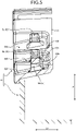
- FIG. 5 is a sectional view of the housing according to the embodiment.
- FIG. 6 is a plan view of a cover according to the embodiment.
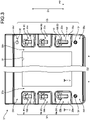
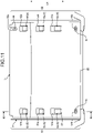
- FIGS. 7 , 9 , and 11 are plan views for describing the attachment of the cover to the housing.
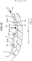
- FIGS. 8 , 10 , and 12 are sectional views for describing the attachment of the cover to the housing.
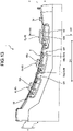
- FIG. 13 is a side view illustrating the cover fixed to the housing.
- FIG. 14 is a sectional view illustrating a discharge route of a foreign substance.
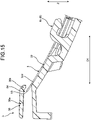
- FIG. 15 is a sectional view illustrating the vicinity of a covering part.
- FIG. 5 illustrates the section along V-V in FIG. 3 .
- FIG. 8 illustrates the section along VIII-VIII in FIG. 7 .
- FIG. 10 illustrates the section along X-X in FIG. 9 .
- FIG. 12 illustrates the section along XII-XII in FIG. 11 .
- FIG. 14 illustrates the section along XIV-XIV in FIG. 13 .
- FIG. 15 illustrates the section along XV-XV in FIG. 14 .
- a projection device 1 includes a housing 4 and a cover 5.
- the housing 4 includes a main body 2 and a lid member 3 that is fitted to the main body 2.
- the main body 2 includes an opening part that opens upward.
- the lid member 3 closes the opening part of the main body 2 from above.
- the projection device 1 As illustrated in FIG. 2 , the projection device 1 according to the embodiment is mounted on a vehicle 100.
- the projection device 1 forms a head-up display.
- the projection device 1 is disposed inside an instrument panel 101, for example.
- the instrument panel 101 includes an opening 101a that opens upward.
- the opening 101a faces a windshield 102 in a vehicle up-down direction Z.
- the lid member 3 includes a wall part 30 including an opening 31.
- the wall part 30 faces the opening part of the main body 2 in the vehicle up-down direction Z.
- the housing 4 is disposed such that the opening 31 faces the opening 101a.
- the housing 4 is disposed such that a first direction D1 to be described below extends along a vehicle front-rear direction X.
- the projection device 1 includes a display device 20, a first mirror 21, and a second mirror 22.
- the display device 20, the first mirror 21, and the second mirror 22 are housed inside the housing 4.
- the display device 20 is a device including a display surface for displaying an image.
- the display device 20 is, for example, a liquid crystal display device such as a thin film transistor-liquid crystal display (TFT-LCD).
- TFT-LCD thin film transistor-liquid crystal display
- the first mirror 21 reflects, toward the second mirror 22, display light 70 emitted from the display device 20.
- the first mirror 21 is a planar mirror, for example.
- the second mirror 22 reflects the display light 70 toward the windshield 102.
- the shape of the reflection surface of the second mirror 22 is, for example, a free curved surface.
- the second mirror 22 is, for example, a concave mirror for magnifying the display light 70.
- the display light 70 reflected by the second mirror 22 passes through the opening 31 and the opening 101a, and is reflected toward a driver 200 by the windshield 102.
- the projection device 1 displays a virtual image to the driver 200 by the display light 70.
- a bezel 103 with a tubular shape is provided in the instrument panel 101.
- the bezel 103 is a wall part that surrounds an optical path of the display light 70 propagating from the opening 31 to the opening 101a.
- the cover 5 is a plate-shaped member that closes the opening 31 of the lid member 3.
- the cover 5 is formed of resin with a light-transmitting property such as polycarbonate (PC) or acrylic, for example.
- the cover 5 may be colorless and transparent, or colored and transparent.
- the cover 5 may have a surface coated for antireflection.
- the cover 5 covers the opening 31 from the outside so as to close the opening 31.
- the cover 5 in this example covers the opening 31 from above.
- the shape of the lid member 3 in a plan view is approximately rectangular.
- first direction D1 the direction along one side of the lid member 3
- second direction D2 the direction along a side intersecting with this one side
- the first direction D1 and the second direction D2 are orthogonal to each other, for example.
- the first direction D1 corresponds to a short-side direction
- the second direction D2 corresponds to a long-side direction.
- the lid member 3 is formed of, for example, synthetic resin such as polypropylene or ABS. As illustrated in FIG. 1 and FIG. 3 , the lid member 3 includes a first edge part 32 and a second edge part 33 that face each other with the opening 31 therebetween. The first edge part 32 and the second edge part 33 extend along the first direction D1. The first edge part 32 and the second edge part 33 face each other in the second direction D2.
- FIG. 4 is a side view of the first edge part 32.
- the curved shape of the second edge part 33 is similar to the curved shape of the first edge part 32.
- the first edge part 32 includes a support surface 32a the shape of which in a side view is an arc or similar to an arc.
- the support surface 32a is curved to the inside of the housing 4.
- the support surface 32a in this example is curved downward in the vehicle up-down direction Z.
- the support surface 32a includes a first end part 32c and a second end part 32d.
- the first end part 32c corresponds to one end part of the support surface 32a in the first direction D1.
- the second end part 32d corresponds to the other end part of the support surface 32a in the first direction D1.
- FIG. 4 illustrates a virtual line IL1 connecting the first end part 32c and the second end part 32d of the support surface 32a.
- a central part 32m of the support surface 32a is positioned below the virtual line IL1.
- the support surface 32a is depressed such that the central part 32m is positioned closer to the main body 2 with respect to the central line IL1.
- the support surface 32a is inclined such that the second end part 32d is positioned higher than the first end part 32c.
- the first edge part 32 includes a plurality of concave parts 32b.
- the concave parts 32b are depressed to the inside of the housing 4 with respect to the support surface 32a.
- the concave parts 32b are disposed at intervals along the first direction D1.
- the first edge part 32 in this example includes three concave parts 32b.
- a bottom surface 32e of each of the concave parts 32b is inclined with respect to the second direction D2.
- the housing 4 is mounted on the vehicle 100 such that the second direction D2 coincides with the vehicle width direction. That is to say, the bottom surface 32e is an inclined surface that is inclined with respect to a horizontal direction in a state where the housing 4 is mounted on the vehicle 100.
- the bottom surface 32e is inclined in a manner of extending downward as the bottom surface 32e extends to the outside of the housing 4 along the second direction D2. Therefore, the bottom surface 32e is inclined so that liquid such as water is discharged to a space beside the housing 4.
- Each concave part 23b includes one claw part 6. That is to say, the first edge part 32 in this example includes three claw parts 6.
- the claw parts 6 are referred to as a first claw part 6a, a second claw part 6b, and a third claw part 6c in the order from the claw part 6 closest to the first end part 32c.
- the claw part 6 protrudes upward from the bottom surface 32e of the concave part 32b.
- the claw part 6 includes a base part 61 and a holding part 62.
- the base part 61 protrudes from the bottom surface 32e to the outside of the housing 4.
- the claw part 6 in this example protrudes upward from the bottom surface 32e.
- the base part 61 protrudes from the bottom surface 32e to the vertical direction, for example.
- the shape of the base part 61 is, for example, a prismatic column shape having an approximately rectangular sectional shape.
- the holding part 62 protrudes along the first direction D1 from a tip end part of the base part 61.
- each holding part 62 protrudes from the base part 61 toward the first end part 32c.
- the shape of the claw part 6 in the side view is an L-like shape in which the holding part 62 is bent toward the first end part 32c with respect to the base part 61.
- the holding part 62 protrudes to the direction parallel to the bottom surface 32e, for example.
- the shape of the holding part 62 is, for example, a prismatic column shape having an approximately rectangular sectional shape.
- the holding part 62 includes a convex part 62a. The convex part 62a rises to the bottom surface 32e.
- the shape of the convex part 62a in the side view is a triangular shape the width of which in the first direction D1 decreases toward the bottom surface 32e.
- the convex part 62a faces a central part of the bottom surface 32e in the first direction D1, for example.
- the holding part 62 supports the cover 5 by the convex part 62a.
- a length L1 of the holding part of the first claw part 6a is larger than a length L2 of the holding part 62 of the second claw part 6b and is larger than a length L3 of the holding part 62 of the third claw part 6c. That is to say, the length L1 of the holding part 62 of the first claw part 6a is larger than the lengths L2 and L3 of the holding part 62 of the claw parts 6b and 6c other than the first claw part 6a. In the present embodiment, the length L2 and the length L3 are the same.
- the first edge part 32 includes a first protrusion 34.
- the first protrusion 34 is provided to the support surface 32a and protrudes upward from the support surface 32a.
- the first protrusion 34 is disposed near the first end part 32c. More specifically, the first protrusion 34 is disposed between the concave part 32b where the first claw part 6a is disposed and the first end part 32c.
- the shape of the first protrusion 34 in this example is a circular column.
- the adjacent concave parts 32b are partitioned by a partition wall 32f.
- An upper surface 32g of the partition wall 32f constitutes a part of the support surface 32a. That is to say, the adjacent two concave parts 32b and 32b are formed in a manner that the support surface 32a is left between the concave parts 32b and 32b.
- the second edge part 33 includes a support surface 33a and a plurality of concave parts 33b.
- the shape of the support surface 33a is similar to the shape of the support surface 32a of the first edge part 32. That is to say, the shape of the support surface 33a is a curved shape that is curved to the inside of the housing 4.
- the support surface 33a includes a first end part 33c and a second end part 33d.
- the first end part 33c is positioned on the same side as the first end part 32c in the first direction D1.
- the support surface 33a is inclined such that the second end part 33d is positioned higher than the first end part 33c.
- the concave parts 33b are disposed at intervals along the first direction D1.
- the second edge part 33 in this example includes three concave parts 33b.
- a bottom surface 33e of each of the concave parts 33b is inclined with respect to the second direction D2.
- the bottom surface 33e is inclined in a manner of extending downward as the bottom surface 33e extends away from the first edge part 32. Therefore, the bottom surface 33e is inclined so that liquid such as water is discharged to a space beside the housing 4.
- Each concave part 33b includes one claw part 6.
- the claw parts 6 of the second edge part 33 are referred to as a first claw part 6d, a second claw part 6e, and a third claw part 6f in the order from the claw part 6 closest to the first end part 33c.
- Each of the claw parts 6 protrudes upward from the bottom surface 33e of the concave part 33b.
- the first claw part 6d is disposed facing the first claw part 6a in the second direction D2.
- the second claw part 6e and the third claw part 6f are disposed facing the second claw part 6b and the third claw part 6c, respectively.
- the claw part 6 of the second edge part 33 includes the base part 61 and the holding part 62 similar to those of the claw part 6 of the first edge part 32.
- the holding part 62 protrudes along the first direction D1 from a tip end part of the base part 61.
- Each holding part 62 protrudes from the base part 61 toward the first end part 33c side.
- the holding part 62 includes the convex part 62a.
- the length of the holding part 62 of the first claw part 6d is larger than the length of the holding parts 62 of the other claw parts 6e and 6f.
- the length of the holding part 62 of the first claw part 6d is equal to the length L1 of the holding part 62 of the first claw part 6a, for example.
- the length of the holding part 62 of the second claw part 6e and the length of the holding part 62 of the third claw part 6f are equal to the length L2 of the holding part 62 of the second claw part 6b and the length L3 of the holding part 62 of the third claw part 6c, for example.
- the second edge part 33 includes the first protrusion 34.
- the first protrusion 34 is provided to the support surface 33a and protrudes upward from the support surface 33a.
- the first protrusion 34 is disposed near the first end part 33c. More specifically, the first protrusion 34 is disposed between the concave part 33b where the first claw part 6d is disposed and the first end part 33c.
- the shape of the first protrusion 34 is a circular column, for example.
- the second edge part 33 includes a second protrusion 35.
- the second protrusion 35 is provided to the support surface 33a and protrudes upward from the support surface 33a.
- the second protrusion 35 is disposed near the second end part 33d. More specifically, the second protrusion 35 is disposed between the concave part 33b where the third claw part 6f is disposed and the second end part 33d.
- the shape of the second protrusion 35 is a circular column, for example.
- the shape of the cover 5 in a plan view is approximately rectangular.
- the cover 5 includes a first edge part 51 and a second edge part 52.
- the first edge part 51 is an edge part corresponding to the first edge part 32 of the lid member 3.
- the second edge part 52 is an edge part corresponding to the second edge part 33 of the lid member 3.
- the first edge part 51 and the second edge part 52 extend in the first direction D1 in a state where the cover 5 is attached to the lid member 3.
- the first edge part 51 and the second edge part 52 are parallel to each other, for example. In the long-side direction of the cover 5 in this example, the direction where the first edge part 51 and the second edge part 52 extend corresponds to the short-side direction.
- the first edge part 51 includes a plurality of through holes 51a.
- the through holes 51a are disposed at intervals in the direction where the first edge part 51 extends.
- the distance between the adjacent through holes 51a and 51a corresponds to the distance between the claw parts 6 of the first edge part 32.
- the shape of the through hole 51a in this example is rectangular.
- the through hole 51a has the width and the length that enable at least the holding part 62 of the corresponding claw part 6 to be inserted thereinto.
- a length L4 of the through hole 51a corresponding to the first claw part 6a is larger than lengths L5 and L6 of the other through holes 51a.
- the first edge part 51 includes a positioning hole 51b.
- the positioning hole 51b corresponds to the first protrusion 34 provided to the first edge part 32.
- the positioning hole 51b is provided to one end of the first edge part 51 in the first direction D1.
- the positioning hole 51b is a through hole penetrating the cover 5.
- the shape of the positioning hole 51b in a plan view is an ellipse the major axis of which coincides with the direction orthogonal to the first direction D1.
- the second edge part 52 includes a plurality of through holes 52a.
- the through holes 52a are disposed at intervals in the direction where the second edge part 52 extends.
- the distance between the adjacent through holes 52a corresponds to the distance between the claw parts 6 of the second edge part 33.
- the shape of the through hole 52a in this example is rectangular.
- the through hole 52a has the width and the length that enable at least the holding part 62 of the corresponding claw part 6 to be inserted thereinto.
- the length of the through hole 52a corresponding to the first claw part 6d is larger than the lengths of the other through holes 52a.
- the second edge part 52 includes a positioning hole 52b.
- the positioning hole 52b corresponds to the first protrusion 34 provided to the second edge part 33.
- the positioning hole 52b is provided to one end of the second edge part 52 in the first direction D1.
- the positioning hole 52b is a through hole penetrating the cover 5.
- the shape of the positioning hole 52b in a plan view is an ellipse the major axis of which coincides with the direction orthogonal to the first direction D1.
- the second edge part 52 includes a notch 52c.
- the notch 52c guides the second protrusion 35 of the lid member 3 so as to position the cover 5 with respect to the lid member 3.
- the notch 52c is provided to a first side 54 of the cover 5.
- the first side 54 is a side facing toward a direction opposite to a protruding direction PD in which the holding parts 62 protrude.
- the notch 52c extends along the first direction D1.
- the width of the notch 52c is a little larger than the outer diameter of the second protrusion 35.
- the shape of a depth part of the notch 52c is an arc matching the shape of the second protrusion 35.
- FIG. 7 and FIG. 8 positions the cover 5 to the lid member 3 as illustrated in FIG. 7 and FIG. 8 . More specifically, the cover 5 is positioned such that the first edge part 51 faces the first edge part 32 of the lid member 3 and the second edge part 52 faces the second edge part 33 of the lid member 3.
- the three through holes 51a face the claw parts 6a, 6b, and 6c of the lid member 3 respectively
- the three through holes 52a face the claw parts 6d, 6e, and 6f of the lid member 3 respectively.
- FIG. 10 illustrates the sections of the first edge part 32 of the lid member 3 and the first edge part 51 of the cover 5.
- the first claw part 6a is inserted into the corresponding through hole 51a.
- the second claw part 6b and the third claw part 6c are deviated from the corresponding through holes 51a. Therefore, the second claw part 6b and the third claw part 6c are in contact with a back surface of the cover 5.
- the second edge part 33 of the lid member 3 and the second edge part 52 of the cover 5 are also in the similar state. That is to say, the first claw part 6d is inserted into the corresponding through hole 52a and the second claw part 6e and the third claw part 6f are in contact with the back surface of the cover 5.
- the operator further slides the cover 5 toward a direction opposite to the protruding direction PD.
- the cover 5 goes under the holding parts 62 of the first claw parts 6a and 6d.
- the second claw parts 6b and 6e and the third claw parts 6c and 6f remain in contact with the back surface of the cover 5.
- the holding parts 62 of the first claw parts 6a and 6d hold the cover 5 and temporarily lock the cover 5.
- the operator can easily keep the cover 5 curved. Accordingly, the operator can easily insert the other claw parts 6b, 6c, 6e, and 6f into the through holes 51a and 52a.
- FIG. 12 illustrates the state in which the cover 5 slides to the space below the second claw parts 6b and 6e and the third claw parts 6c and 6f.
- FIG. 11 illustrates the state in which the cover 5 has gone under the second claw parts 6b and 6e and the third claw parts 6c and 6f.
- the operator further slides the cover 5 in the direction opposite to the protruding direction PD.
- the cover 5 is kept at a predetermined holding position as illustrated in FIG. 13 .
- the lid member 3 holds the cover 5 between the first edge part 32 and the holding parts 62 inserted into the through hole 51a in a manner that the cover 5 is curved. More specifically, the lid member 3 holds the cover 5 between the convex parts 62a of the holding parts 62 and the support surface 32a.
- the cover 5 is held in a manner of being curved along the support surface 32a. That is to say, the cover 5 is held between the support surface 32a and the holding parts 62 by the elastic restoring force of the cover 5.
- the lid member 3 holds the cover 5 between the second edge part 33 and the claw parts 6 similarly as described above. That is to say, at the holding position, the lid member 3 holds the cover 5 between the second edge part 33 and the holding parts 62 inserted into the through holes 52a in a manner that the cover 5 is curved. More specifically, the lid member 3 holds the cover 5 between the convex parts 62a of the holding parts 62 and the support surface 33a. The cover 5 is held in a manner of being curved along the support surface 33a. That is to say, the cover 5 is held between the support surface 33a and the holding parts 62 by the elastic restoring force of the cover 5.
- the first protrusion 34 protrudes from the cover 5 as illustrated in FIG. 13 .
- the two first protrusions 34 of the lid member 3 are inserted into the positioning holes 51b and 52b.
- the first protrusions 34 are fitted to the positioning holes 51b and 52b.
- the first protrusions 34 restrict the movement of the cover 5 along the first direction D1 and position the cover 5.
- the second protrusion 35 of the lid member 3 enters the notch 52c of the cover 5 as illustrated in FIG. 1 .
- the second protrusion 35 restricts the movement of the cover 5 along the second direction D2 and positions the cover 5.
- the cover 5 is held by the lid member 3 at a predetermined position and is fixed to the lid member 3.
- the entry of foreign substances into the housing 4 can be suppressed as described below.
- a foreign substance such as liquid may drop into the concave part 32b from the gap between the claw part 6 and the through hole 51a.
- the bottom surface 32e of the concave part 32b is inclined so that the foreign substance is discharged to the space beside the housing 4.
- the foreign substance having entered the concave part 32b is discharged to the space beside the housing 4.
- the three sides of the concave part 32b other than the discharge port are surrounded by walls.
- the entry of the foreign substances into the housing 4 is suppressed as appropriate.
- the foreign substance having entered through the gap between the claw part 6 and the through hole 52a is discharged to the space beside the housing 4 by the bottom surface 33e of the concave part 33b.
- the projection device 1 includes a covering part 36 that covers an end face 53 of the cover 5 as illustrated in FIG. 15 .
- the covering part 36 constitutes a part of the lid member 3, and is formed integrally with the first edge part 32 and the second edge part 33.
- the end face 53 of the cover 5 is an end face positioned at the first side 54. When the cover 5 is held by the lid member 3, the end face 53 faces obliquely upward.
- one end of the covering part 36 in the second direction D2 connects to the first edge part 32.
- the other end of the covering part 36 in the second direction D2 connects to the second edge part 33. That is to say, the covering part 36 continues from one end to the other end of the lid member 3 in the second direction D2.
- the covering part 36 includes a main body 36a and an inclination part 36b.
- the main body 36a is a flat-plate part and extends approximately horizontally.
- the inclination part 36b extends obliquely downward from a tip end of the main body 36a.
- the inclination angle of the inclination part 36b with respect to the first direction D1 is similar to the inclination angle of the cover 5 with respect to the first direction D1.
- the inclination part 36b overlaps with the first side 54 of the cover 5. In other words, an end part of the cover 5 that includes the first side 54 is covered with the inclination part 36b.
- the lid member 3 is configured such that when the cover 5 is attached to the lid member 3, the first side 54 goes under the covering part 36. More specifically, there is a gap below the covering part 36 and the cover 5 can enter this gap. When the cover 5 is attached to the lid member 3, the end part of the cover 5 goes under the covering part 36 while sliding along the first edge part 32 and the second edge part 33.
- the covering part 36 is configured to suppress the generation of stray light. For example, when external light such as sunlight is reflected by the end face 53, stray light is generated and the visibility of an image may deteriorate. In this regard, the covering part 36 can shield the end face 53 from the external light and suppress the generation of the stray light.
- the covering part 36 is formed integrally with the first edge part 32 and the second edge part 33. Therefore, an additional member for shielding the end face 53 from light is unnecessary, the number of components is reduced, and the workability of the assembling work is improved. Moreover, the size of the cover 5 can be reduced to minimize the size of the projection device 1. Furthermore, the shape and the depth of the bezel 103 do not need to be adjusted for preventing stray light and the limitation on the design on the vehicle 100 side is removed.
- the lid member 3 may include, in addition to the covering part 36 that covers the end face 53, a covering part that covers end faces of the first edge part 51 and the second edge part 52.
- the projection device 1 includes the housing 4 and the plate-shaped cover 5.
- the housing 4 includes the wall part 30 including the opening 31.
- the opening 31 allows the display light 70 to pass toward the outside.
- the cover 5 has a light-transmitting property and closes the opening 31 from the outside.
- the wall part 30 includes the first edge part 32, the second edge part 33, and the claw parts 6.
- the first edge part 32 and the second edge part 33 are a pair of edge parts facing each other with the opening 31 therebetween and extending along the first direction D1.
- the claw parts 6 are arranged along the first direction D1 at the first edge part 32 and the second edge part 33.
- the first edge part 32 and the second edge part 33 are curved to the inside of the housing 4.
- the cover 5 includes the through holes 51a and 52a arranged correspondingly to the claw parts 6.
- Each of the claw parts 6 includes the base part 61 and the holding part 62.
- the base part 61 protrudes from the first edge part 32 or the second edge part 33 to the outside.
- the holding part 62 protrudes from the tip end part of the base part 61 along the first direction D1.
- the housing 4 holds the cover 5 between the holding parts 62 inserted into the through holes 51a and 52a and the edge parts 32 and 33 in a manner that the cover 5 is curved.
- the cover 5 is held between the holding parts 62 and the edge parts 32 and 33.
- the cover 5 can be fixed to the housing 4 without the use of an adhesive agent or an adhesive tape. Therefore, the projection device 1 according to the present embodiment can reduce the number of components.
- a material that is not deformed easily at the contact with the adhesive agent needs to be selected as the material of the cover 5. That is to say, the material of the cover 5 is likely to be restricted.
- the material of the cover 5 is not likely to be restricted.
- the cover 5 is held by the claw parts 6, the expansion and contraction of the cover 5 due to heat are easily allowed.
- the cover 5 may distort due to the expansion and contraction of the cover 5.
- the claw parts 6 allow the expansion and contraction of the cover 5 and can suppress the distortion of the cover 5.
- the claw parts 6 disposed along the edge parts 32 and 33 include the first claw parts 6a and 6d positioned at the end part in the first direction D1.
- the length of the holding parts 62 of the first claw parts 6a and 6d is larger than the length of the holding parts 62 of the claw parts 6 other than the first claw parts 6a and 6d.
- the length L1 of the holding part 62 of the first claw part 6a is larger than the lengths L2 and L3 of the holding parts 62 of the other claw parts 6. Therefore, the first claw parts 6a and 6d can be used as the holding parts with respect to the cover 5 and the workability of the assembling work is improved.
- the first claw parts 6a and 6d according to the present embodiment are positioned at an end part in the protruding direction PD.
- the protruding direction PD corresponds to the direction where the holding part 62 protrudes.
- the cover 5 includes the first side 54.
- the first side 54 is a side facing toward a direction opposite to the protruding direction PD.
- the housing 4 includes the covering part 36 covering the first side 54 in a state where the cover 5 is held by the holding parts 62 and the edge parts 32 and 33. Therefore, the housing 4 can suppress the generation of stray light.
- the cover 5 includes the positioning holes 51b and 52b.
- the housing 4 includes the first protrusions 34.
- the first protrusions 34 are fitted to the positioning holes 51b and 52b in the state where the cover 5 is held by the holding parts 62 and the edge parts 32 and 33. With this structure, the cover 5 can be positioned and the displacement of the cover 5 can be suppressed.
- the cover 5 includes the notch 52c provided to the first side 54.
- the housing 4 includes the second protrusion 35 that locks the notch 52c to position the cover 5.
- the second protrusion 35 locks the notch 52c in the second direction D2, for example.
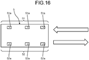
- FIG. 16 is a plan view of a cover according to a modification of the embodiment.
- the sliding direction when the cover 5 is assembled to the lid member 3 is not limited to the direction illustrated in the embodiment.
- the sliding direction of the cover 5 may be a direction from the second end parts 32d and 33d of the lid member 3 to the first end parts 32c and 33c.
- the protruding direction PD in this case is opposite to the direction in FIG. 3 .
- the sliding direction of the cover 5 may be parallel to the long-side direction of the lid member 3.
- the first edge part 51 and the second edge part 52 are edge parts extending along the long-side direction of the cover 5 as illustrated in FIG. 16 .
- the through holes 51a and 52a are arranged along the long-side direction of the cover 5.
- the claw parts 6 are arranged at edge parts along the long-side direction of the lid member 3.
- the positions of the first claw parts 6a and 6d are not limited to the positions illustrated in the embodiment.
- the first claw parts 6a and 6d are positioned at the end parts on the side of the first end parts 32c and 33c in the aforementioned embodiment.
- the first claw parts 6a and 6d may be positioned at the end parts on the side of the second end parts 32d and 33d.
- the positions of the first claw parts 6a and 6d are not limited to the end positions among the claw parts 6.
- each of the first edge part 32 and the second edge part 33 may include one claw part 6.
- the one claw part 6 may be disposed so as to support a central part of the cover 5 in the first direction D1. Both end parts of the cover 5 are supported by the support surfaces 32a and 33a, for example.
- Each of the first edge part 32 and the second edge part 33 may include four or more claw parts 6.
- the distance between the claw parts 6 is not limited to the distance illustrated in the example.
- the claw parts 6 may be arranged such that the base parts 61 are disposed at equal intervals, for example.
- the first claw parts 6a and 6d may be disposed with a distance different from the distance between the other claw parts 6.
- the distance from the first claw parts 6a and 6d to the second claw parts 6b and 6e may be different from the distance from the second claw parts 6b and 6e to the third claw parts 6c and 6f.
- the claw parts 6 are arranged depending on the shape of the housing 4 to improve the assembling property.
- the length of the holding parts 62 of the first claw parts 6a and 6d is larger than the length of the holding parts 62 of the other claw parts 6; however, the structure is not limited to this example. For example, all the holding parts 62 may have an equal length.
- FIG. 17 is a perspective view of a first claw part and a concave part according to the modification of the embodiment.
- FIG. 18 is a perspective view of another concave part according to the modification of the embodiment.
- a first claw part 6g illustrated in FIG. 17 is a modification of the first claw part 6a of the embodiment.
- a length L11 of the holding part 62 of the first claw part 6g is smaller than the length L2 of the holding part 62 of the second claw part 6b and the length L3 of the holding part 62 of the third claw part 6c.
- a length L21 of the concave part 32b where the first claw part 6g is disposed may be equal to the length of the concave part 32b where the first claw part 6a is disposed. In this case, the length L21 is larger than the length of the concave parts 32b where the second claw part 6b and the third claw part 6c are disposed.
- the corresponding through hole 51a may also be short.
- the length L4 (refer to FIG. 6 ) of the through hole 51a corresponding to the first claw part 6g is smaller than the lengths L5 and L6 of the other through holes 51a.
- the length of the concave part 32b where the first claw part 6g is disposed may be set in accordance with the length L11 of the holding part 62 of the first claw part 6g.
- a length L22 of the concave part 32b illustrated in FIG. 18 is smaller than the length of the concave parts 32b where the second claw part 6b and the third claw part 6c are disposed.
- the length of the concave part 32b may be set in accordance with the length of the holding part 62 disposed in the concave part 32b.
- the length of the concave part 32b is determined depending on the lengths L4, L5, and L6 of the corresponding through holes 51a. That is to say, the length of the concave part 32b is determined so that a foreign substance entering through the through hole 51a can be discharged by the concave part 32b.
- the length of the holding part 62 of the first claw part 6d at the second edge part 33 may be equal to the length L11 of the holding part 62 of the first claw part 6g.
- the length of the concave part 32b where the first claw part 6d is disposed may be equal to either the length L21 or the length L22.
- first protrusions 34 and the number of second protrusions 35 are not limited to the numbers illustrated in the drawings.
- the second protrusion 35 may be provided to the first edge part 32 in addition to the second edge part 33.
- the cover 5 includes two notches 52c.
- the projection device 1 is not limited to a so-called head-up display.
- the structure of the housing 4 and the cover 5 is applicable to various devices that project images.
- the projection device includes the housing including the wall part including the opening, and the cover with the plate shape having a light-transmitting property and closing the opening from the outside.
- the wall part includes a pair of edge parts extending along the first direction, and the claw parts disposed along the first direction at each of the pair of edge parts.
- the pair of edge parts is curved to the inside of the housing.
- the cover includes the through holes disposed correspondingly to the claw parts.
- Each of the claw parts includes the base part and the holding part protruding from the tip end part of the base part along the first direction.
- the housing sandwiches the cover between the edge parts and the holding parts inserted into the through holes and holds the cover in a state where the cover is curved.
- the projection device is advantageous in that the projection device can be configured with fewer components.
Landscapes
- Physics & Mathematics (AREA)
- Engineering & Computer Science (AREA)
- General Physics & Mathematics (AREA)
- Chemical & Material Sciences (AREA)
- Combustion & Propulsion (AREA)
- Transportation (AREA)
- Mechanical Engineering (AREA)
- Optics & Photonics (AREA)
- Instrument Panels (AREA)
- Casings For Electric Apparatus (AREA)
Abstract
Description
- The present invention relates to a projection device.
- Conventionally, devices for projecting images have been used.
Japanese Patent Application Laid-open No. 2019-152795 Japanese Patent Application Laid-open No. 2019-152795 - A projection device for projecting an image is desired to include as few components as possible. The number of components can be reduced if a cover can be fixed to a housing without the use of an adhesive agent or an adhesive tape.
- It is an object of the present invention to provide a projection device that can be structured with fewer components.
- In order to achieve the above mentioned object, a projection device according to one aspect of the present invention includes a housing including a wall part including an opening that allows display light to pass toward outside; and a cover with a plate shape having a light-transmitting property and closing the opening from the outside, wherein the wall part includes a pair of edge parts facing each other with the opening therebetween and extending along a first direction, and a plurality of claw parts disposed along the first direction at each of the pair of edge parts, the pair of edge parts is curved to inside of the housing, the cover includes a plurality of through holes disposed correspondingly to the claw parts, each of the claw parts includes a base part protruding from the edge part toward the outside and a holding part protruding from a tip end part of the base part along the first direction, and the housing sandwiches the cover between the edge parts and the holding parts inserted into the through holes and holds the cover in a state where the cover is curved.
- According to another aspect of the present invention, in the projection device, it is preferable that the claw parts disposed along each of the edge parts include a first claw part positioned at an end part in the first direction, and a length of the holding part of the first claw part is larger than a length of the holding part of the claw part other than the first claw part.
- According to still another aspect of the present invention, in the projection device, it is preferable that the first claw part is positioned at an end part in a protruding direction in which the holding part protrudes.
- According to still another aspect of the present invention, in the projection device, it is preferable that the cover includes a first side that is a side facing toward a direction opposite to the protruding direction in which the holding part protrudes, and the housing includes a covering part that covers the first side in a state where the cover is held by the holding parts and the edge parts.
- According to still another aspect of the present invention, in the projection device, it is preferable that the cover includes a positioning hole, and the housing includes a first protrusion to be fitted to the positioning hole in a state where the cover is held by the holding parts and the edge parts.
- According to still another aspect of the present invention, in the projection device, it is preferable that the cover includes a notch provided at a first side that is a side facing toward a direction opposite to the protruding direction in which the holding part protrudes, and the housing includes a second protrusion that locks the notch so as to position the cover.
- The above and other objects, features, advantages and technical and industrial significance of this invention will be better understood by reading the following detailed description of presently preferred embodiments of the invention, when considered in connection with the accompanying drawings.
-
-
FIG. 1 is a perspective view of a projection device according to an embodiment; -
FIG. 2 is a schematic structure diagram of a vehicle where the projection device according to the embodiment is mounted; -
FIG. 3 is a plan view of a housing according to the embodiment; -
FIG. 4 is a side view of the housing according to the embodiment; -
FIG. 5 is a sectional view of the housing according to the embodiment; -
FIG. 6 is a plan view of a cover according to the embodiment; -
FIG. 7 is a plan view for describing the attachment of the cover to the housing; -
FIG. 8 is a sectional view for describing the attachment of the cover to the housing; -
FIG. 9 is a plan view for describing the attachment of the cover to the housing; -
FIG. 10 is a sectional view for describing the attachment of the cover to the housing; -
FIG. 11 is a plan view for describing the attachment of the cover to the housing; -
FIG. 12 is a sectional view for describing the attachment of the cover to the housing; -
FIG. 13 is a side view illustrating the cover fixed to the housing; -
FIG. 14 is a sectional view illustrating a discharge route of a foreign substance; -
FIG. 15 is a sectional view illustrating the vicinity of a covering part; -
FIG. 16 is a plan view of a cover according to a modification of the embodiment; -
FIG. 17 is a perspective view of a first claw part and a concave part according to the modification of the embodiment; and -
FIG. 18 is a perspective view of another concave part according to the modification of the embodiment. - A projection device according to an embodiment of the present invention is hereinafter described in detail with reference to the drawings. The present invention is not limited by this embodiment. The components in the embodiment below include components that are easily conceivable by a person skilled in the art and substantially equivalent components.
- An embodiment is described with reference to
FIG. 1 to FIG. 15 . The present embodiment is related to a projection device.FIG. 1 is a perspective view of a projection device according to the embodiment.FIG. 2 is a schematic structure diagram of a vehicle where the projection device according to the embodiment is mounted.FIG. 3 is a plan view of a housing according to the embodiment.FIG. 4 is a side view of the housing according to the embodiment.FIG. 5 is a sectional view of the housing according to the embodiment.FIG. 6 is a plan view of a cover according to the embodiment.FIGS. 7 ,9 , and11 are plan views for describing the attachment of the cover to the housing.FIGS. 8 ,10 , and12 are sectional views for describing the attachment of the cover to the housing. -
FIG. 13 is a side view illustrating the cover fixed to the housing.FIG. 14 is a sectional view illustrating a discharge route of a foreign substance.FIG. 15 is a sectional view illustrating the vicinity of a covering part.FIG. 5 illustrates the section along V-V inFIG. 3 .FIG. 8 illustrates the section along VIII-VIII inFIG. 7 .FIG. 10 illustrates the section along X-X inFIG. 9 .FIG. 12 illustrates the section along XII-XII inFIG. 11 .FIG. 14 illustrates the section along XIV-XIV inFIG. 13 .FIG. 15 illustrates the section along XV-XV inFIG. 14 . - As illustrated in
FIG. 1 andFIG. 2 , a projection device 1 according to the present embodiment includes ahousing 4 and acover 5. Thehousing 4 includes amain body 2 and alid member 3 that is fitted to themain body 2. Themain body 2 includes an opening part that opens upward. Thelid member 3 closes the opening part of themain body 2 from above. - As illustrated in
FIG. 2 , the projection device 1 according to the embodiment is mounted on avehicle 100. The projection device 1 forms a head-up display. The projection device 1 is disposed inside aninstrument panel 101, for example. Theinstrument panel 101 includes anopening 101a that opens upward. Theopening 101a faces awindshield 102 in a vehicle up-down direction Z. - The
lid member 3 includes awall part 30 including anopening 31. Thewall part 30 faces the opening part of themain body 2 in the vehicle up-down direction Z. Thehousing 4 is disposed such that theopening 31 faces theopening 101a. Thehousing 4 is disposed such that a first direction D1 to be described below extends along a vehicle front-rear direction X. The projection device 1 includes adisplay device 20, afirst mirror 21, and asecond mirror 22. Thedisplay device 20, thefirst mirror 21, and thesecond mirror 22 are housed inside thehousing 4. Thedisplay device 20 is a device including a display surface for displaying an image. Thedisplay device 20 is, for example, a liquid crystal display device such as a thin film transistor-liquid crystal display (TFT-LCD). - The
first mirror 21 reflects, toward thesecond mirror 22,display light 70 emitted from thedisplay device 20. Thefirst mirror 21 is a planar mirror, for example. Thesecond mirror 22 reflects thedisplay light 70 toward thewindshield 102. The shape of the reflection surface of thesecond mirror 22 is, for example, a free curved surface. Thesecond mirror 22 is, for example, a concave mirror for magnifying thedisplay light 70. - The
display light 70 reflected by thesecond mirror 22 passes through theopening 31 and theopening 101a, and is reflected toward adriver 200 by thewindshield 102. The projection device 1 displays a virtual image to thedriver 200 by thedisplay light 70. In theinstrument panel 101, abezel 103 with a tubular shape is provided. Thebezel 103 is a wall part that surrounds an optical path of thedisplay light 70 propagating from theopening 31 to theopening 101a. - The
cover 5 is a plate-shaped member that closes theopening 31 of thelid member 3. Thecover 5 is formed of resin with a light-transmitting property such as polycarbonate (PC) or acrylic, for example. Thecover 5 may be colorless and transparent, or colored and transparent. Thecover 5 may have a surface coated for antireflection. Thecover 5 covers the opening 31 from the outside so as to close theopening 31. Thecover 5 in this example covers the opening 31 from above. - As illustrated in
FIG. 1 andFIG. 3 , the shape of thelid member 3 in a plan view is approximately rectangular. In the description below, the direction along one side of thelid member 3 is referred to as "first direction D1" and the direction along a side intersecting with this one side is referred to as "second direction D2". The first direction D1 and the second direction D2 are orthogonal to each other, for example. In thelid member 3 in this example, the first direction D1 corresponds to a short-side direction and the second direction D2 corresponds to a long-side direction. - The
lid member 3 is formed of, for example, synthetic resin such as polypropylene or ABS. As illustrated inFIG. 1 andFIG. 3 , thelid member 3 includes afirst edge part 32 and asecond edge part 33 that face each other with theopening 31 therebetween. Thefirst edge part 32 and thesecond edge part 33 extend along the first direction D1. Thefirst edge part 32 and thesecond edge part 33 face each other in the second direction D2. - As illustrated in
FIG. 1 andFIG. 4 , thefirst edge part 32 and thesecond edge part 33 are curved to the inside of thehousing 4.FIG. 4 is a side view of thefirst edge part 32. The curved shape of thesecond edge part 33 is similar to the curved shape of thefirst edge part 32. As illustrated inFIG. 4 , thefirst edge part 32 includes asupport surface 32a the shape of which in a side view is an arc or similar to an arc. Thesupport surface 32a is curved to the inside of thehousing 4. Thesupport surface 32a in this example is curved downward in the vehicle up-down direction Z. Thesupport surface 32a includes afirst end part 32c and asecond end part 32d. Thefirst end part 32c corresponds to one end part of thesupport surface 32a in the first direction D1. Thesecond end part 32d corresponds to the other end part of thesupport surface 32a in the first direction D1. -
FIG. 4 illustrates a virtual line IL1 connecting thefirst end part 32c and thesecond end part 32d of thesupport surface 32a. Acentral part 32m of thesupport surface 32a is positioned below the virtual line IL1. In other words, thesupport surface 32a is depressed such that thecentral part 32m is positioned closer to themain body 2 with respect to the central line IL1. Thesupport surface 32a is inclined such that thesecond end part 32d is positioned higher than thefirst end part 32c. - The
first edge part 32 includes a plurality ofconcave parts 32b. Theconcave parts 32b are depressed to the inside of thehousing 4 with respect to thesupport surface 32a. Theconcave parts 32b are disposed at intervals along the first direction D1. Thefirst edge part 32 in this example includes threeconcave parts 32b. As illustrated inFIG. 5 , abottom surface 32e of each of theconcave parts 32b is inclined with respect to the second direction D2. Thehousing 4 is mounted on thevehicle 100 such that the second direction D2 coincides with the vehicle width direction. That is to say, thebottom surface 32e is an inclined surface that is inclined with respect to a horizontal direction in a state where thehousing 4 is mounted on thevehicle 100. Thebottom surface 32e is inclined in a manner of extending downward as thebottom surface 32e extends to the outside of thehousing 4 along the second direction D2. Therefore, thebottom surface 32e is inclined so that liquid such as water is discharged to a space beside thehousing 4. - Each concave part 23b includes one
claw part 6. That is to say, thefirst edge part 32 in this example includes threeclaw parts 6. In the description below, theclaw parts 6 are referred to as afirst claw part 6a, asecond claw part 6b, and athird claw part 6c in the order from theclaw part 6 closest to thefirst end part 32c. - Each of the
claw parts 6 protrudes upward from thebottom surface 32e of theconcave part 32b. Theclaw part 6 includes abase part 61 and a holdingpart 62. Thebase part 61 protrudes from thebottom surface 32e to the outside of thehousing 4. Theclaw part 6 in this example protrudes upward from thebottom surface 32e. Thebase part 61 protrudes from thebottom surface 32e to the vertical direction, for example. The shape of thebase part 61 is, for example, a prismatic column shape having an approximately rectangular sectional shape. - The holding
part 62 protrudes along the first direction D1 from a tip end part of thebase part 61. In thehousing 4 in this example, each holdingpart 62 protrudes from thebase part 61 toward thefirst end part 32c. That is to say, the shape of theclaw part 6 in the side view is an L-like shape in which the holdingpart 62 is bent toward thefirst end part 32c with respect to thebase part 61. The holdingpart 62 protrudes to the direction parallel to thebottom surface 32e, for example. The shape of the holdingpart 62 is, for example, a prismatic column shape having an approximately rectangular sectional shape. The holdingpart 62 includes aconvex part 62a. Theconvex part 62a rises to thebottom surface 32e. The shape of theconvex part 62a in the side view is a triangular shape the width of which in the first direction D1 decreases toward thebottom surface 32e. Theconvex part 62a faces a central part of thebottom surface 32e in the first direction D1, for example. The holdingpart 62 supports thecover 5 by theconvex part 62a. - As illustrated in
FIG. 4 , a length L1 of the holding part of thefirst claw part 6a is larger than a length L2 of the holdingpart 62 of thesecond claw part 6b and is larger than a length L3 of the holdingpart 62 of thethird claw part 6c. That is to say, the length L1 of the holdingpart 62 of thefirst claw part 6a is larger than the lengths L2 and L3 of the holdingpart 62 of theclaw parts first claw part 6a. In the present embodiment, the length L2 and the length L3 are the same. - The
first edge part 32 includes afirst protrusion 34. Thefirst protrusion 34 is provided to thesupport surface 32a and protrudes upward from thesupport surface 32a. Thefirst protrusion 34 is disposed near thefirst end part 32c. More specifically, thefirst protrusion 34 is disposed between theconcave part 32b where thefirst claw part 6a is disposed and thefirst end part 32c. The shape of thefirst protrusion 34 in this example is a circular column. - The adjacent
concave parts 32b are partitioned by apartition wall 32f. Anupper surface 32g of thepartition wall 32f constitutes a part of thesupport surface 32a. That is to say, the adjacent twoconcave parts support surface 32a is left between theconcave parts - As illustrated in
FIG. 3 , thesecond edge part 33 includes asupport surface 33a and a plurality ofconcave parts 33b. The shape of thesupport surface 33a is similar to the shape of thesupport surface 32a of thefirst edge part 32. That is to say, the shape of thesupport surface 33a is a curved shape that is curved to the inside of thehousing 4. Thesupport surface 33a includes afirst end part 33c and asecond end part 33d. Thefirst end part 33c is positioned on the same side as thefirst end part 32c in the first direction D1. Thesupport surface 33a is inclined such that thesecond end part 33d is positioned higher than thefirst end part 33c. - The
concave parts 33b are disposed at intervals along the first direction D1. Thesecond edge part 33 in this example includes threeconcave parts 33b. Abottom surface 33e of each of theconcave parts 33b is inclined with respect to the second direction D2. Thebottom surface 33e is inclined in a manner of extending downward as thebottom surface 33e extends away from thefirst edge part 32. Therefore, thebottom surface 33e is inclined so that liquid such as water is discharged to a space beside thehousing 4. - Each
concave part 33b includes oneclaw part 6. In the description below, theclaw parts 6 of thesecond edge part 33 are referred to as afirst claw part 6d, asecond claw part 6e, and athird claw part 6f in the order from theclaw part 6 closest to thefirst end part 33c. - Each of the
claw parts 6 protrudes upward from thebottom surface 33e of theconcave part 33b. Thefirst claw part 6d is disposed facing thefirst claw part 6a in the second direction D2. Similarly, thesecond claw part 6e and thethird claw part 6f are disposed facing thesecond claw part 6b and thethird claw part 6c, respectively. - The
claw part 6 of thesecond edge part 33 includes thebase part 61 and the holdingpart 62 similar to those of theclaw part 6 of thefirst edge part 32. The holdingpart 62 protrudes along the first direction D1 from a tip end part of thebase part 61. Each holdingpart 62 protrudes from thebase part 61 toward thefirst end part 33c side. The holdingpart 62 includes theconvex part 62a. In theclaw parts 6 of thesecond edge part 33, the length of the holdingpart 62 of thefirst claw part 6d is larger than the length of the holdingparts 62 of theother claw parts part 62 of thefirst claw part 6d is equal to the length L1 of the holdingpart 62 of thefirst claw part 6a, for example. The length of the holdingpart 62 of thesecond claw part 6e and the length of the holdingpart 62 of thethird claw part 6f are equal to the length L2 of the holdingpart 62 of thesecond claw part 6b and the length L3 of the holdingpart 62 of thethird claw part 6c, for example. - The
second edge part 33 includes thefirst protrusion 34. Thefirst protrusion 34 is provided to thesupport surface 33a and protrudes upward from thesupport surface 33a. Thefirst protrusion 34 is disposed near thefirst end part 33c. More specifically, thefirst protrusion 34 is disposed between theconcave part 33b where thefirst claw part 6d is disposed and thefirst end part 33c. The shape of thefirst protrusion 34 is a circular column, for example. - The
second edge part 33 includes asecond protrusion 35. Thesecond protrusion 35 is provided to thesupport surface 33a and protrudes upward from thesupport surface 33a. Thesecond protrusion 35 is disposed near thesecond end part 33d. More specifically, thesecond protrusion 35 is disposed between theconcave part 33b where thethird claw part 6f is disposed and thesecond end part 33d. The shape of thesecond protrusion 35 is a circular column, for example. - As illustrated in
FIG. 6 , the shape of thecover 5 in a plan view is approximately rectangular. Thecover 5 includes afirst edge part 51 and asecond edge part 52. Thefirst edge part 51 is an edge part corresponding to thefirst edge part 32 of thelid member 3. Thesecond edge part 52 is an edge part corresponding to thesecond edge part 33 of thelid member 3. Thefirst edge part 51 and thesecond edge part 52 extend in the first direction D1 in a state where thecover 5 is attached to thelid member 3. Thefirst edge part 51 and thesecond edge part 52 are parallel to each other, for example. In the long-side direction of thecover 5 in this example, the direction where thefirst edge part 51 and thesecond edge part 52 extend corresponds to the short-side direction. - The
first edge part 51 includes a plurality of throughholes 51a. The throughholes 51a are disposed at intervals in the direction where thefirst edge part 51 extends. The distance between the adjacent throughholes claw parts 6 of thefirst edge part 32. The shape of the throughhole 51a in this example is rectangular. The throughhole 51a has the width and the length that enable at least the holdingpart 62 of thecorresponding claw part 6 to be inserted thereinto. A length L4 of the throughhole 51a corresponding to thefirst claw part 6a is larger than lengths L5 and L6 of the other throughholes 51a. - The
first edge part 51 includes apositioning hole 51b. Thepositioning hole 51b corresponds to thefirst protrusion 34 provided to thefirst edge part 32. Thepositioning hole 51b is provided to one end of thefirst edge part 51 in the first direction D1. Thepositioning hole 51b is a through hole penetrating thecover 5. The shape of thepositioning hole 51b in a plan view is an ellipse the major axis of which coincides with the direction orthogonal to the first direction D1. - The
second edge part 52 includes a plurality of throughholes 52a. The throughholes 52a are disposed at intervals in the direction where thesecond edge part 52 extends. The distance between the adjacent throughholes 52a corresponds to the distance between theclaw parts 6 of thesecond edge part 33. The shape of the throughhole 52a in this example is rectangular. The throughhole 52a has the width and the length that enable at least the holdingpart 62 of thecorresponding claw part 6 to be inserted thereinto. The length of the throughhole 52a corresponding to thefirst claw part 6d is larger than the lengths of the other throughholes 52a. - The
second edge part 52 includes apositioning hole 52b. Thepositioning hole 52b corresponds to thefirst protrusion 34 provided to thesecond edge part 33. Thepositioning hole 52b is provided to one end of thesecond edge part 52 in the first direction D1. Thepositioning hole 52b is a through hole penetrating thecover 5. The shape of thepositioning hole 52b in a plan view is an ellipse the major axis of which coincides with the direction orthogonal to the first direction D1. - The
second edge part 52 includes anotch 52c. Thenotch 52c guides thesecond protrusion 35 of thelid member 3 so as to position thecover 5 with respect to thelid member 3. Thenotch 52c is provided to afirst side 54 of thecover 5. Thefirst side 54 is a side facing toward a direction opposite to a protruding direction PD in which the holdingparts 62 protrude. Thenotch 52c extends along the first direction D1. The width of thenotch 52c is a little larger than the outer diameter of thesecond protrusion 35. The shape of a depth part of thenotch 52c is an arc matching the shape of thesecond protrusion 35. - Here, a method for attaching the
cover 5 to thelid member 3 is described. An operator positions thecover 5 to thelid member 3 as illustrated inFIG. 7 andFIG. 8 . More specifically, thecover 5 is positioned such that thefirst edge part 51 faces thefirst edge part 32 of thelid member 3 and thesecond edge part 52 faces thesecond edge part 33 of thelid member 3. Here, the three throughholes 51a face theclaw parts lid member 3 respectively, and the three throughholes 52a face theclaw parts lid member 3 respectively. - Next, the operator inserts the
first claw parts holes FIG. 9 andFIG. 10 . The operator places his/her finger on asecond side 55 of thecover 5 and pressespoints holes lid member 3.FIG. 10 illustrates the sections of thefirst edge part 32 of thelid member 3 and thefirst edge part 51 of thecover 5. As thepoint 51d is pressed and thecover 5 is curved accordingly, thefirst claw part 6a is inserted into the corresponding throughhole 51a. At this time, thesecond claw part 6b and thethird claw part 6c are deviated from the corresponding throughholes 51a. Therefore, thesecond claw part 6b and thethird claw part 6c are in contact with a back surface of thecover 5. - The
second edge part 33 of thelid member 3 and thesecond edge part 52 of thecover 5 are also in the similar state. That is to say, thefirst claw part 6d is inserted into the corresponding throughhole 52a and thesecond claw part 6e and thethird claw part 6f are in contact with the back surface of thecover 5. - The operator further slides the
cover 5 toward a direction opposite to the protruding direction PD. Thus, thecover 5 goes under the holdingparts 62 of thefirst claw parts second claw parts third claw parts cover 5. The holdingparts 62 of thefirst claw parts cover 5 and temporarily lock thecover 5. Thus, the operator can easily keep thecover 5 curved. Accordingly, the operator can easily insert theother claw parts holes - The operator further slides the
cover 5 in the direction opposite to the protruding direction PD. Thus, thecover 5 goes under the holdingparts 62 of thesecond claw parts parts 62 of thethird claw parts FIG. 11 andFIG. 12. FIG. 12 illustrates the state in which thecover 5 slides to the space below thesecond claw parts third claw parts FIG. 11 illustrates the state in which thecover 5 has gone under thesecond claw parts third claw parts - The operator further slides the
cover 5 in the direction opposite to the protruding direction PD. Thus, thecover 5 is kept at a predetermined holding position as illustrated inFIG. 13 . At the holding position illustrated inFIG. 13 , thelid member 3 holds thecover 5 between thefirst edge part 32 and the holdingparts 62 inserted into the throughhole 51a in a manner that thecover 5 is curved. More specifically, thelid member 3 holds thecover 5 between theconvex parts 62a of the holdingparts 62 and thesupport surface 32a. Thecover 5 is held in a manner of being curved along thesupport surface 32a. That is to say, thecover 5 is held between thesupport surface 32a and the holdingparts 62 by the elastic restoring force of thecover 5. - Note that the
lid member 3 holds thecover 5 between thesecond edge part 33 and theclaw parts 6 similarly as described above. That is to say, at the holding position, thelid member 3 holds thecover 5 between thesecond edge part 33 and the holdingparts 62 inserted into the throughholes 52a in a manner that thecover 5 is curved. More specifically, thelid member 3 holds thecover 5 between theconvex parts 62a of the holdingparts 62 and thesupport surface 33a. Thecover 5 is held in a manner of being curved along thesupport surface 33a. That is to say, thecover 5 is held between thesupport surface 33a and the holdingparts 62 by the elastic restoring force of thecover 5. - At the holding position, the
first protrusion 34 protrudes from thecover 5 as illustrated inFIG. 13 . As illustrated inFIG. 1 , the twofirst protrusions 34 of thelid member 3 are inserted into the positioning holes 51b and 52b. In other words, thefirst protrusions 34 are fitted to the positioning holes 51b and 52b. Thefirst protrusions 34 restrict the movement of thecover 5 along the first direction D1 and position thecover 5. Moreover, at the holding position, thesecond protrusion 35 of thelid member 3 enters thenotch 52c of thecover 5 as illustrated inFIG. 1 . Thesecond protrusion 35 restricts the movement of thecover 5 along the second direction D2 and positions thecover 5. Thecover 5 is held by thelid member 3 at a predetermined position and is fixed to thelid member 3. - In the projection device 1 according to the present embodiment, the entry of foreign substances into the
housing 4 can be suppressed as described below. As illustrated inFIG. 14 , a foreign substance such as liquid may drop into theconcave part 32b from the gap between theclaw part 6 and the throughhole 51a. As described above, thebottom surface 32e of theconcave part 32b is inclined so that the foreign substance is discharged to the space beside thehousing 4. Thus, the foreign substance having entered theconcave part 32b is discharged to the space beside thehousing 4. The three sides of theconcave part 32b other than the discharge port are surrounded by walls. Thus, the entry of the foreign substances into thehousing 4 is suppressed as appropriate. Similarly, the foreign substance having entered through the gap between theclaw part 6 and the throughhole 52a is discharged to the space beside thehousing 4 by thebottom surface 33e of theconcave part 33b. - The projection device 1 according to the present embodiment includes a covering
part 36 that covers anend face 53 of thecover 5 as illustrated inFIG. 15 . The coveringpart 36 constitutes a part of thelid member 3, and is formed integrally with thefirst edge part 32 and thesecond edge part 33. The end face 53 of thecover 5 is an end face positioned at thefirst side 54. When thecover 5 is held by thelid member 3, theend face 53 faces obliquely upward. - As illustrated in
FIG. 4 , one end of the coveringpart 36 in the second direction D2 connects to thefirst edge part 32. The other end of the coveringpart 36 in the second direction D2 connects to thesecond edge part 33. That is to say, the coveringpart 36 continues from one end to the other end of thelid member 3 in the second direction D2. - As illustrated in
FIG. 15 , the coveringpart 36 includes amain body 36a and aninclination part 36b. Themain body 36a is a flat-plate part and extends approximately horizontally. Theinclination part 36b extends obliquely downward from a tip end of themain body 36a. The inclination angle of theinclination part 36b with respect to the first direction D1 is similar to the inclination angle of thecover 5 with respect to the first direction D1. When thecover 5 is held by thelid member 3, theinclination part 36b overlaps with thefirst side 54 of thecover 5. In other words, an end part of thecover 5 that includes thefirst side 54 is covered with theinclination part 36b. - The
lid member 3 is configured such that when thecover 5 is attached to thelid member 3, thefirst side 54 goes under the coveringpart 36. More specifically, there is a gap below the coveringpart 36 and thecover 5 can enter this gap. When thecover 5 is attached to thelid member 3, the end part of thecover 5 goes under the coveringpart 36 while sliding along thefirst edge part 32 and thesecond edge part 33. - The covering
part 36 is configured to suppress the generation of stray light. For example, when external light such as sunlight is reflected by theend face 53, stray light is generated and the visibility of an image may deteriorate. In this regard, the coveringpart 36 can shield the end face 53 from the external light and suppress the generation of the stray light. - In the
lid member 3 according to the present embodiment, the coveringpart 36 is formed integrally with thefirst edge part 32 and thesecond edge part 33. Therefore, an additional member for shielding the end face 53 from light is unnecessary, the number of components is reduced, and the workability of the assembling work is improved. Moreover, the size of thecover 5 can be reduced to minimize the size of the projection device 1. Furthermore, the shape and the depth of thebezel 103 do not need to be adjusted for preventing stray light and the limitation on the design on thevehicle 100 side is removed. Thelid member 3 may include, in addition to the coveringpart 36 that covers theend face 53, a covering part that covers end faces of thefirst edge part 51 and thesecond edge part 52. - As described above, the projection device 1 according to the present embodiment includes the
housing 4 and the plate-shapedcover 5. Thehousing 4 includes thewall part 30 including theopening 31. Theopening 31 allows thedisplay light 70 to pass toward the outside. Thecover 5 has a light-transmitting property and closes theopening 31 from the outside. Thewall part 30 includes thefirst edge part 32, thesecond edge part 33, and theclaw parts 6. Thefirst edge part 32 and thesecond edge part 33 are a pair of edge parts facing each other with theopening 31 therebetween and extending along the first direction D1. Theclaw parts 6 are arranged along the first direction D1 at thefirst edge part 32 and thesecond edge part 33. - The
first edge part 32 and thesecond edge part 33 are curved to the inside of thehousing 4. Thecover 5 includes the throughholes claw parts 6. Each of theclaw parts 6 includes thebase part 61 and the holdingpart 62. Thebase part 61 protrudes from thefirst edge part 32 or thesecond edge part 33 to the outside. The holdingpart 62 protrudes from the tip end part of thebase part 61 along the first direction D1. Thehousing 4 holds thecover 5 between the holdingparts 62 inserted into the throughholes edge parts cover 5 is curved. - In the projection device 1 according to the present embodiment, the
cover 5 is held between the holdingparts 62 and theedge parts cover 5 can be fixed to thehousing 4 without the use of an adhesive agent or an adhesive tape. Therefore, the projection device 1 according to the present embodiment can reduce the number of components. In the case of fixing thecover 5 to thehousing 4 with an adhesive agent, a material that is not deformed easily at the contact with the adhesive agent needs to be selected as the material of thecover 5. That is to say, the material of thecover 5 is likely to be restricted. On the other hand, in the projection device 1 according to the present embodiment, the material of thecover 5 is not likely to be restricted. - Moreover, since the
cover 5 is held by theclaw parts 6, the expansion and contraction of thecover 5 due to heat are easily allowed. For example, when thecover 5 is fixed to thehousing 4 with an adhesive agent, thecover 5 may distort due to the expansion and contraction of thecover 5. Theclaw parts 6 allow the expansion and contraction of thecover 5 and can suppress the distortion of thecover 5. - In the projection device 1 according to the present embodiment, the
claw parts 6 disposed along theedge parts first claw parts parts 62 of thefirst claw parts parts 62 of theclaw parts 6 other than thefirst claw parts part 62 of thefirst claw part 6a is larger than the lengths L2 and L3 of the holdingparts 62 of theother claw parts 6. Therefore, thefirst claw parts cover 5 and the workability of the assembling work is improved. - The
first claw parts part 62 protrudes. With this structure, the operator can make thefirst claw parts cover 5. - The
cover 5 according to the present embodiment includes thefirst side 54. Thefirst side 54 is a side facing toward a direction opposite to the protruding direction PD. Thehousing 4 includes the coveringpart 36 covering thefirst side 54 in a state where thecover 5 is held by the holdingparts 62 and theedge parts housing 4 can suppress the generation of stray light. - The
cover 5 according to the present embodiment includes the positioning holes 51b and 52b. Thehousing 4 includes thefirst protrusions 34. Thefirst protrusions 34 are fitted to the positioning holes 51b and 52b in the state where thecover 5 is held by the holdingparts 62 and theedge parts cover 5 can be positioned and the displacement of thecover 5 can be suppressed. - The
cover 5 according to the present embodiment includes thenotch 52c provided to thefirst side 54. Thehousing 4 includes thesecond protrusion 35 that locks thenotch 52c to position thecover 5. Thesecond protrusion 35 locks thenotch 52c in the second direction D2, for example. With this structure, thecover 5 can be positioned and the displacement of thecover 5 can be suppressed. -
FIG. 16 is a plan view of a cover according to a modification of the embodiment. The sliding direction when thecover 5 is assembled to thelid member 3 is not limited to the direction illustrated in the embodiment. In the example inFIG. 3 , the sliding direction of thecover 5 may be a direction from thesecond end parts lid member 3 to thefirst end parts FIG. 3 . The sliding direction of thecover 5 may be parallel to the long-side direction of thelid member 3. In this case, thefirst edge part 51 and thesecond edge part 52 are edge parts extending along the long-side direction of thecover 5 as illustrated inFIG. 16 . The throughholes cover 5. Theclaw parts 6 are arranged at edge parts along the long-side direction of thelid member 3. - The positions of the
first claw parts first claw parts first end parts first claw parts second end parts first claw parts claw parts 6. - The number of
claw parts 6 is not limited to the number in the drawings. For example, each of thefirst edge part 32 and thesecond edge part 33 may include oneclaw part 6. In this case, the oneclaw part 6 may be disposed so as to support a central part of thecover 5 in the first direction D1. Both end parts of thecover 5 are supported by the support surfaces 32a and 33a, for example. Each of thefirst edge part 32 and thesecond edge part 33 may include four ormore claw parts 6. - The distance between the
claw parts 6 is not limited to the distance illustrated in the example. Theclaw parts 6 may be arranged such that thebase parts 61 are disposed at equal intervals, for example. Thefirst claw parts other claw parts 6. For example, the distance from thefirst claw parts second claw parts second claw parts third claw parts claw parts 6 are arranged depending on the shape of thehousing 4 to improve the assembling property. - In the aforementioned embodiment, the length of the holding
parts 62 of thefirst claw parts parts 62 of theother claw parts 6; however, the structure is not limited to this example. For example, all the holdingparts 62 may have an equal length. - The holding
part 62 of the first claw part may be shorter than the holdingparts 62 of theother claw parts 6.FIG. 17 is a perspective view of a first claw part and a concave part according to the modification of the embodiment.FIG. 18 is a perspective view of another concave part according to the modification of the embodiment. Afirst claw part 6g illustrated inFIG. 17 is a modification of thefirst claw part 6a of the embodiment. A length L11 of the holdingpart 62 of thefirst claw part 6g is smaller than the length L2 of the holdingpart 62 of thesecond claw part 6b and the length L3 of the holdingpart 62 of thethird claw part 6c. A length L21 of theconcave part 32b where thefirst claw part 6g is disposed may be equal to the length of theconcave part 32b where thefirst claw part 6a is disposed. In this case, the length L21 is larger than the length of theconcave parts 32b where thesecond claw part 6b and thethird claw part 6c are disposed. - In the case where the holding
part 62 of thefirst claw part 6g is short as illustrated inFIG. 17 , the corresponding throughhole 51a may also be short. For example, the length L4 (refer toFIG. 6 ) of the throughhole 51a corresponding to thefirst claw part 6g is smaller than the lengths L5 and L6 of the other throughholes 51a. - Note that the length of the
concave part 32b where thefirst claw part 6g is disposed may be set in accordance with the length L11 of the holdingpart 62 of thefirst claw part 6g. A length L22 of theconcave part 32b illustrated inFIG. 18 is smaller than the length of theconcave parts 32b where thesecond claw part 6b and thethird claw part 6c are disposed. In this manner, the length of theconcave part 32b may be set in accordance with the length of the holdingpart 62 disposed in theconcave part 32b. The length of theconcave part 32b is determined depending on the lengths L4, L5, and L6 of the corresponding throughholes 51a. That is to say, the length of theconcave part 32b is determined so that a foreign substance entering through the throughhole 51a can be discharged by theconcave part 32b. - The length of the holding
part 62 of thefirst claw part 6d at thesecond edge part 33 may be equal to the length L11 of the holdingpart 62 of thefirst claw part 6g. The length of theconcave part 32b where thefirst claw part 6d is disposed may be equal to either the length L21 or the length L22. - The number of
first protrusions 34 and the number ofsecond protrusions 35 are not limited to the numbers illustrated in the drawings. For example, thesecond protrusion 35 may be provided to thefirst edge part 32 in addition to thesecond edge part 33. In this case, thecover 5 includes twonotches 52c. - The projection device 1 is not limited to a so-called head-up display. The structure of the
housing 4 and thecover 5 is applicable to various devices that project images. - The contents disclosed in the aforementioned embodiment and modification can be implemented in combination as appropriate.
- The projection device according to the embodiment includes the housing including the wall part including the opening, and the cover with the plate shape having a light-transmitting property and closing the opening from the outside. The wall part includes a pair of edge parts extending along the first direction, and the claw parts disposed along the first direction at each of the pair of edge parts. The pair of edge parts is curved to the inside of the housing. The cover includes the through holes disposed correspondingly to the claw parts. Each of the claw parts includes the base part and the holding part protruding from the tip end part of the base part along the first direction. The housing sandwiches the cover between the edge parts and the holding parts inserted into the through holes and holds the cover in a state where the cover is curved. The projection device according to the embodiment is advantageous in that the projection device can be configured with fewer components.
- Although the invention has been described with respect to specific embodiments for a complete and clear disclosure, the appended claims are not to be thus limited but are to be construed as embodying all modifications and alternative constructions that may occur to one skilled in the art that fairly fall within the basic teaching herein set forth.
Claims (6)
- A projection device (1) comprising:a housing (4) including a wall part (30) including an opening (31) that allows display light (70) to pass toward outside; anda cover (5) with a plate shape having a light-transmitting property and closing the opening (31) from the outside, whereinthe wall part (30) includes a pair of edge parts (32, 33) facing each other with the opening (31) therebetween and extending along a first direction (D1), and a plurality of claw parts (6) disposed along the first direction (D1) at each of the pair of edge parts (32, 33),the pair of edge parts (32, 33) is curved to inside of the housing (4),the cover (5) includes a plurality of through holes (51a, 52a) disposed correspondingly to the claw parts (6),each of the claw parts (6) includes a base part (61) protruding from the edge part (32,33) toward the outside and a holding part (62) protruding from a tip end part of the base part (61) along the first direction (D1), andthe housing (4) sandwiches the cover (5) between the edge parts (32, 33) and the holding parts (62) inserted into the through holes (51a, 52a) and holds the cover (5) in a state where the cover (5) is curved.
- The projection device (1) according to claim 1, whereinthe claw parts (6) disposed along each of the edge parts (32, 33) include a first claw part (6a, 6d) positioned at an end part in the first direction (D1), anda length of the holding part (62) of the first claw part (6a, 6d) is larger than a length of the holding part (62) of the claw part (6) other than the first claw part (6a, 6d).
- The projection device (1) according to claim 2, wherein the first claw part (6a, 6d) is positioned at an end part in a protruding direction (PD) in which the holding part (62) protrudes.
- The projection device (1) according to any one of claims 1 to 3, whereinthe cover (5) includes a first side (54) that is a side facing toward a direction opposite to a protruding direction (PD) in which the holding part (62) protrudes, andthe housing (4) includes a covering part (36) that covers the first side (54) in a state where the cover (5) is held by the holding parts (62) and the edge parts (32, 33) .
- The projection device (1) according to any one of claims 1 to 4, whereinthe cover (5) includes a positioning hole (51b, 52b), andthe housing (4) includes a first protrusion (34) to be fitted to the positioning hole (51b, 52b) in a state where the cover (5) is held by the holding parts (62) and the edge parts (32, 33).
- The projection device (1) according to any one of claims 1 to 5, whereinthe cover (5) includes a notch (52c) provided at a first side (54) that is a side facing toward a direction opposite to a protruding direction (PD) in which the holding part (62) protrudes, andthe housing (4) includes a second protrusion (35) that locks the notch (52c) so as to position the cover (5).
Applications Claiming Priority (1)
| Application Number | Priority Date | Filing Date | Title |
|---|---|---|---|
| JP2021020344A JP7264924B2 (en) | 2021-02-12 | 2021-02-12 | projection device |
Publications (2)
| Publication Number | Publication Date |
|---|---|
| EP4043958A1 true EP4043958A1 (en) | 2022-08-17 |
| EP4043958B1 EP4043958B1 (en) | 2023-02-22 |
Family
ID=80119579
Family Applications (1)
| Application Number | Title | Priority Date | Filing Date |
|---|---|---|---|
| EP22154485.1A Active EP4043958B1 (en) | 2021-02-12 | 2022-02-01 | Projection device |
Country Status (4)
| Country | Link |
|---|---|
| US (1) | US11619868B2 (en) |
| EP (1) | EP4043958B1 (en) |
| JP (1) | JP7264924B2 (en) |
| CN (1) | CN114924412B (en) |
Citations (5)
| Publication number | Priority date | Publication date | Assignee | Title |
|---|---|---|---|---|
| US20120250280A1 (en) * | 2009-12-25 | 2012-10-04 | Nippon Seiki Co., Ltd. | Instrument device |
| JP2019152795A (en) | 2018-03-05 | 2019-09-12 | 日本精機株式会社 | Head-up display device |
| WO2019208423A1 (en) * | 2018-04-25 | 2019-10-31 | 日本精機株式会社 | Head-up display device and method for assembling same |
| DE102018120926A1 (en) * | 2018-08-28 | 2020-03-05 | Valeo Schalter Und Sensoren Gmbh | Head-up display for a motor vehicle with a damping element between a cover device and a housing device and method |
| US20210041696A1 (en) * | 2019-08-06 | 2021-02-11 | Denso International America, Inc. | Heads-up display with irrigation trough |
Family Cites Families (16)
| Publication number | Priority date | Publication date | Assignee | Title |
|---|---|---|---|---|
| JPH03134718A (en) | 1989-10-20 | 1991-06-07 | Toshiba Corp | Portable electronic apparatus |
| JP3642272B2 (en) * | 2000-09-25 | 2005-04-27 | 日本ビクター株式会社 | Optical element fixing structure |
| JP2009037753A (en) * | 2007-07-31 | 2009-02-19 | Kyocera Mita Corp | Operation panel, and image forming device equipped with it |
| JP4994214B2 (en) * | 2007-12-21 | 2012-08-08 | 三菱電機株式会社 | Cover locking mechanism |
| JP2010276776A (en) * | 2009-05-27 | 2010-12-09 | Nippon Seiki Co Ltd | Head-up display device |
| JP5759812B2 (en) * | 2011-07-12 | 2015-08-05 | 新電元工業株式会社 | Cover connection structure and cover connection method |
| JP2015073030A (en) * | 2013-10-03 | 2015-04-16 | シャープ株式会社 | Electronics |
| JP6582140B2 (en) * | 2016-09-21 | 2019-09-25 | 富士フイルム株式会社 | Projection display |
| JP6652102B2 (en) * | 2017-04-13 | 2020-02-19 | 株式会社デンソー | Step motors and pointer instruments for vehicles |
| JP2018182653A (en) * | 2017-04-20 | 2018-11-15 | 三菱電機株式会社 | Fixing mechanism of combiner, head-up display device and head-up display device for vehicle |
| JP6984449B2 (en) * | 2017-06-30 | 2021-12-22 | 日本精機株式会社 | Head-up display |
| WO2019208422A1 (en) * | 2018-04-23 | 2019-10-31 | 日本精機株式会社 | Head-up display device and method for manufacturing same |
| WO2020009092A1 (en) * | 2018-07-04 | 2020-01-09 | 日本精機株式会社 | Head-up display |
| JP7135807B2 (en) * | 2018-12-06 | 2022-09-13 | ティアック株式会社 | Electronics |
| JP2020117106A (en) * | 2019-01-25 | 2020-08-06 | 日本精機株式会社 | Driving device used in head-up display device and head-up display device |
| US11933981B2 (en) * | 2021-02-01 | 2024-03-19 | Honda Motor Co., Ltd. | Heads-up display unit with integrated protection system |
-
2021
- 2021-02-12 JP JP2021020344A patent/JP7264924B2/en active Active
-
2022
- 2022-02-01 EP EP22154485.1A patent/EP4043958B1/en active Active
- 2022-02-08 CN CN202210118507.1A patent/CN114924412B/en active Active
- 2022-02-09 US US17/668,370 patent/US11619868B2/en active Active
Patent Citations (5)
| Publication number | Priority date | Publication date | Assignee | Title |
|---|---|---|---|---|
| US20120250280A1 (en) * | 2009-12-25 | 2012-10-04 | Nippon Seiki Co., Ltd. | Instrument device |
| JP2019152795A (en) | 2018-03-05 | 2019-09-12 | 日本精機株式会社 | Head-up display device |
| WO2019208423A1 (en) * | 2018-04-25 | 2019-10-31 | 日本精機株式会社 | Head-up display device and method for assembling same |
| DE102018120926A1 (en) * | 2018-08-28 | 2020-03-05 | Valeo Schalter Und Sensoren Gmbh | Head-up display for a motor vehicle with a damping element between a cover device and a housing device and method |
| US20210041696A1 (en) * | 2019-08-06 | 2021-02-11 | Denso International America, Inc. | Heads-up display with irrigation trough |
Also Published As
| Publication number | Publication date |
|---|---|
| US11619868B2 (en) | 2023-04-04 |
| CN114924412B (en) | 2024-04-26 |
| EP4043958B1 (en) | 2023-02-22 |
| US20220269153A1 (en) | 2022-08-25 |
| JP7264924B2 (en) | 2023-04-25 |
| JP2022123194A (en) | 2022-08-24 |
| CN114924412A (en) | 2022-08-19 |
Similar Documents
| Publication | Publication Date | Title |
|---|---|---|
| EP3062141B1 (en) | Display apparatus | |
| KR100595796B1 (en) | Surface lighting device and liquid crystal display using the same | |
| US20080079863A1 (en) | Liquid Crystal Display Device | |
| EP4043958B1 (en) | Projection device | |
| US8646962B2 (en) | Light guiding plate, lighting apparatus, and display apparatus | |
| JP6053473B2 (en) | Guideline structure | |
| KR20060066092A (en) | Backlight device and display device having same | |
| JP2010276776A (en) | Head-up display device | |
| KR20130019974A (en) | Back-light unit and display device having the same | |
| KR101212134B1 (en) | Liquid crystal display | |
| JP4853708B2 (en) | Pointer-type instrument | |
| JP7783228B2 (en) | Vehicle display device | |
| WO2021215400A1 (en) | Vehicular display device | |
| JP7761610B2 (en) | Display and vehicle display device | |
| JP2022085985A (en) | Head-up display | |
| JP7791145B2 (en) | Vehicle display device | |
| US20260029643A1 (en) | Head-up display apparatus | |
| US20250271669A1 (en) | Head-up display | |
| JP7435327B2 (en) | Vehicle display device | |
| JP6116204B2 (en) | Guideline structure | |
| JP7383948B2 (en) | heads up display | |
| JP2025086955A (en) | Display device and head-up display device | |
| EP4163712A1 (en) | Display device, head-up display, and mobile object | |
| JP2024124848A (en) | Display device | |
| JP2018189382A (en) | Display device for vehicle |
Legal Events
| Date | Code | Title | Description |
|---|---|---|---|
| PUAI | Public reference made under article 153(3) epc to a published international application that has entered the european phase |
Free format text: ORIGINAL CODE: 0009012 |
|
| STAA | Information on the status of an ep patent application or granted ep patent |
Free format text: STATUS: REQUEST FOR EXAMINATION WAS MADE |
|
| 17P | Request for examination filed |
Effective date: 20220201 |
|
| AK | Designated contracting states |
Kind code of ref document: A1 Designated state(s): AL AT BE BG CH CY CZ DE DK EE ES FI FR GB GR HR HU IE IS IT LI LT LU LV MC MK MT NL NO PL PT RO RS SE SI SK SM TR |
|
| GRAP | Despatch of communication of intention to grant a patent |
Free format text: ORIGINAL CODE: EPIDOSNIGR1 |
|
| STAA | Information on the status of an ep patent application or granted ep patent |
Free format text: STATUS: GRANT OF PATENT IS INTENDED |
|
| INTG | Intention to grant announced |
Effective date: 20221207 |
|
| GRAS | Grant fee paid |
Free format text: ORIGINAL CODE: EPIDOSNIGR3 |
|
| GRAA | (expected) grant |
Free format text: ORIGINAL CODE: 0009210 |
|
| STAA | Information on the status of an ep patent application or granted ep patent |
Free format text: STATUS: THE PATENT HAS BEEN GRANTED |
|
| AK | Designated contracting states |
Kind code of ref document: B1 Designated state(s): AL AT BE BG CH CY CZ DE DK EE ES FI FR GB GR HR HU IE IS IT LI LT LU LV MC MK MT NL NO PL PT RO RS SE SI SK SM TR |
|
| REG | Reference to a national code |
Ref country code: GB Ref legal event code: FG4D |
|
| REG | Reference to a national code |
Ref country code: CH Ref legal event code: EP |
|
| REG | Reference to a national code |
Ref country code: AT Ref legal event code: REF Ref document number: 1549916 Country of ref document: AT Kind code of ref document: T Effective date: 20230315 Ref country code: IE Ref legal event code: FG4D |
|
| REG | Reference to a national code |
Ref country code: DE Ref legal event code: R096 Ref document number: 602022000013 Country of ref document: DE |
|
| RAP4 | Party data changed (patent owner data changed or rights of a patent transferred) |
Owner name: YAZAKI CORPORATION |
|
| REG | Reference to a national code |
Ref country code: LT Ref legal event code: MG9D |
|
| REG | Reference to a national code |
Ref country code: NL Ref legal event code: MP Effective date: 20230222 |
|
| REG | Reference to a national code |
Ref country code: AT Ref legal event code: MK05 Ref document number: 1549916 Country of ref document: AT Kind code of ref document: T Effective date: 20230222 |
|
| PG25 | Lapsed in a contracting state [announced via postgrant information from national office to epo] |
Ref country code: RS Free format text: LAPSE BECAUSE OF FAILURE TO SUBMIT A TRANSLATION OF THE DESCRIPTION OR TO PAY THE FEE WITHIN THE PRESCRIBED TIME-LIMIT Effective date: 20230222 Ref country code: PT Free format text: LAPSE BECAUSE OF FAILURE TO SUBMIT A TRANSLATION OF THE DESCRIPTION OR TO PAY THE FEE WITHIN THE PRESCRIBED TIME-LIMIT Effective date: 20230622 Ref country code: NO Free format text: LAPSE BECAUSE OF FAILURE TO SUBMIT A TRANSLATION OF THE DESCRIPTION OR TO PAY THE FEE WITHIN THE PRESCRIBED TIME-LIMIT Effective date: 20230522 Ref country code: NL Free format text: LAPSE BECAUSE OF FAILURE TO SUBMIT A TRANSLATION OF THE DESCRIPTION OR TO PAY THE FEE WITHIN THE PRESCRIBED TIME-LIMIT Effective date: 20230222 Ref country code: LV Free format text: LAPSE BECAUSE OF FAILURE TO SUBMIT A TRANSLATION OF THE DESCRIPTION OR TO PAY THE FEE WITHIN THE PRESCRIBED TIME-LIMIT Effective date: 20230222 Ref country code: LT Free format text: LAPSE BECAUSE OF FAILURE TO SUBMIT A TRANSLATION OF THE DESCRIPTION OR TO PAY THE FEE WITHIN THE PRESCRIBED TIME-LIMIT Effective date: 20230222 Ref country code: HR Free format text: LAPSE BECAUSE OF FAILURE TO SUBMIT A TRANSLATION OF THE DESCRIPTION OR TO PAY THE FEE WITHIN THE PRESCRIBED TIME-LIMIT Effective date: 20230222 Ref country code: ES Free format text: LAPSE BECAUSE OF FAILURE TO SUBMIT A TRANSLATION OF THE DESCRIPTION OR TO PAY THE FEE WITHIN THE PRESCRIBED TIME-LIMIT Effective date: 20230222 Ref country code: AT Free format text: LAPSE BECAUSE OF FAILURE TO SUBMIT A TRANSLATION OF THE DESCRIPTION OR TO PAY THE FEE WITHIN THE PRESCRIBED TIME-LIMIT Effective date: 20230222 |
|
| PG25 | Lapsed in a contracting state [announced via postgrant information from national office to epo] |
Ref country code: SE Free format text: LAPSE BECAUSE OF FAILURE TO SUBMIT A TRANSLATION OF THE DESCRIPTION OR TO PAY THE FEE WITHIN THE PRESCRIBED TIME-LIMIT Effective date: 20230222 Ref country code: PL Free format text: LAPSE BECAUSE OF FAILURE TO SUBMIT A TRANSLATION OF THE DESCRIPTION OR TO PAY THE FEE WITHIN THE PRESCRIBED TIME-LIMIT Effective date: 20230222 Ref country code: IS Free format text: LAPSE BECAUSE OF FAILURE TO SUBMIT A TRANSLATION OF THE DESCRIPTION OR TO PAY THE FEE WITHIN THE PRESCRIBED TIME-LIMIT Effective date: 20230622 Ref country code: GR Free format text: LAPSE BECAUSE OF FAILURE TO SUBMIT A TRANSLATION OF THE DESCRIPTION OR TO PAY THE FEE WITHIN THE PRESCRIBED TIME-LIMIT Effective date: 20230523 Ref country code: FI Free format text: LAPSE BECAUSE OF FAILURE TO SUBMIT A TRANSLATION OF THE DESCRIPTION OR TO PAY THE FEE WITHIN THE PRESCRIBED TIME-LIMIT Effective date: 20230222 |
|
| PG25 | Lapsed in a contracting state [announced via postgrant information from national office to epo] |
Ref country code: SM Free format text: LAPSE BECAUSE OF FAILURE TO SUBMIT A TRANSLATION OF THE DESCRIPTION OR TO PAY THE FEE WITHIN THE PRESCRIBED TIME-LIMIT Effective date: 20230222 Ref country code: RO Free format text: LAPSE BECAUSE OF FAILURE TO SUBMIT A TRANSLATION OF THE DESCRIPTION OR TO PAY THE FEE WITHIN THE PRESCRIBED TIME-LIMIT Effective date: 20230222 Ref country code: EE Free format text: LAPSE BECAUSE OF FAILURE TO SUBMIT A TRANSLATION OF THE DESCRIPTION OR TO PAY THE FEE WITHIN THE PRESCRIBED TIME-LIMIT Effective date: 20230222 Ref country code: DK Free format text: LAPSE BECAUSE OF FAILURE TO SUBMIT A TRANSLATION OF THE DESCRIPTION OR TO PAY THE FEE WITHIN THE PRESCRIBED TIME-LIMIT Effective date: 20230222 Ref country code: CZ Free format text: LAPSE BECAUSE OF FAILURE TO SUBMIT A TRANSLATION OF THE DESCRIPTION OR TO PAY THE FEE WITHIN THE PRESCRIBED TIME-LIMIT Effective date: 20230222 |
|
| REG | Reference to a national code |
Ref country code: DE Ref legal event code: R097 Ref document number: 602022000013 Country of ref document: DE |
|
| PG25 | Lapsed in a contracting state [announced via postgrant information from national office to epo] |
Ref country code: SK Free format text: LAPSE BECAUSE OF FAILURE TO SUBMIT A TRANSLATION OF THE DESCRIPTION OR TO PAY THE FEE WITHIN THE PRESCRIBED TIME-LIMIT Effective date: 20230222 |
|
| PLBE | No opposition filed within time limit |
Free format text: ORIGINAL CODE: 0009261 |
|
| STAA | Information on the status of an ep patent application or granted ep patent |
Free format text: STATUS: NO OPPOSITION FILED WITHIN TIME LIMIT |
|
| 26N | No opposition filed |
Effective date: 20231123 |
|
| PG25 | Lapsed in a contracting state [announced via postgrant information from national office to epo] |
Ref country code: SI Free format text: LAPSE BECAUSE OF FAILURE TO SUBMIT A TRANSLATION OF THE DESCRIPTION OR TO PAY THE FEE WITHIN THE PRESCRIBED TIME-LIMIT Effective date: 20230222 |
|
| PG25 | Lapsed in a contracting state [announced via postgrant information from national office to epo] |
Ref country code: IT Free format text: LAPSE BECAUSE OF FAILURE TO SUBMIT A TRANSLATION OF THE DESCRIPTION OR TO PAY THE FEE WITHIN THE PRESCRIBED TIME-LIMIT Effective date: 20230222 |
|
| REG | Reference to a national code |
Ref country code: DE Ref legal event code: R119 Ref document number: 602022000013 Country of ref document: DE |
|
| PG25 | Lapsed in a contracting state [announced via postgrant information from national office to epo] |
Ref country code: MC Free format text: LAPSE BECAUSE OF FAILURE TO SUBMIT A TRANSLATION OF THE DESCRIPTION OR TO PAY THE FEE WITHIN THE PRESCRIBED TIME-LIMIT Effective date: 20230222 |
|
| PG25 | Lapsed in a contracting state [announced via postgrant information from national office to epo] |
Ref country code: LU Free format text: LAPSE BECAUSE OF NON-PAYMENT OF DUE FEES Effective date: 20240201 |
|
| PG25 | Lapsed in a contracting state [announced via postgrant information from national office to epo] |
Ref country code: LU Free format text: LAPSE BECAUSE OF NON-PAYMENT OF DUE FEES Effective date: 20240201 |
|
| PG25 | Lapsed in a contracting state [announced via postgrant information from national office to epo] |
Ref country code: BG Free format text: LAPSE BECAUSE OF FAILURE TO SUBMIT A TRANSLATION OF THE DESCRIPTION OR TO PAY THE FEE WITHIN THE PRESCRIBED TIME-LIMIT Effective date: 20230222 |
|
| PG25 | Lapsed in a contracting state [announced via postgrant information from national office to epo] |
Ref country code: BG Free format text: LAPSE BECAUSE OF FAILURE TO SUBMIT A TRANSLATION OF THE DESCRIPTION OR TO PAY THE FEE WITHIN THE PRESCRIBED TIME-LIMIT Effective date: 20230222 |
|
| REG | Reference to a national code |
Ref country code: BE Ref legal event code: MM Effective date: 20240229 |
|
| PG25 | Lapsed in a contracting state [announced via postgrant information from national office to epo] |
Ref country code: DE Free format text: LAPSE BECAUSE OF NON-PAYMENT OF DUE FEES Effective date: 20240903 |
|
| PG25 | Lapsed in a contracting state [announced via postgrant information from national office to epo] |
Ref country code: BE Free format text: LAPSE BECAUSE OF NON-PAYMENT OF DUE FEES Effective date: 20240229 |
|
| PG25 | Lapsed in a contracting state [announced via postgrant information from national office to epo] |
Ref country code: FR Free format text: LAPSE BECAUSE OF NON-PAYMENT OF DUE FEES Effective date: 20240229 |
|
| PG25 | Lapsed in a contracting state [announced via postgrant information from national office to epo] |
Ref country code: IE Free format text: LAPSE BECAUSE OF NON-PAYMENT OF DUE FEES Effective date: 20240201 |
|
| PG25 | Lapsed in a contracting state [announced via postgrant information from national office to epo] |
Ref country code: IE Free format text: LAPSE BECAUSE OF NON-PAYMENT OF DUE FEES Effective date: 20240201 Ref country code: FR Free format text: LAPSE BECAUSE OF NON-PAYMENT OF DUE FEES Effective date: 20240229 Ref country code: DE Free format text: LAPSE BECAUSE OF NON-PAYMENT OF DUE FEES Effective date: 20240903 Ref country code: BE Free format text: LAPSE BECAUSE OF NON-PAYMENT OF DUE FEES Effective date: 20240229 |
|
| PG25 | Lapsed in a contracting state [announced via postgrant information from national office to epo] |
Ref country code: CY Free format text: LAPSE BECAUSE OF FAILURE TO SUBMIT A TRANSLATION OF THE DESCRIPTION OR TO PAY THE FEE WITHIN THE PRESCRIBED TIME-LIMIT; INVALID AB INITIO Effective date: 20220201 |
|
| REG | Reference to a national code |
Ref country code: CH Ref legal event code: PL |
|
| PG25 | Lapsed in a contracting state [announced via postgrant information from national office to epo] |
Ref country code: CH Free format text: LAPSE BECAUSE OF NON-PAYMENT OF DUE FEES Effective date: 20250228 |
|
| PG25 | Lapsed in a contracting state [announced via postgrant information from national office to epo] |
Ref country code: TR Free format text: LAPSE BECAUSE OF FAILURE TO SUBMIT A TRANSLATION OF THE DESCRIPTION OR TO PAY THE FEE WITHIN THE PRESCRIBED TIME-LIMIT Effective date: 20230222 |