EP4043937A1 - Optical fiber cable production method, and optical fiber cable - Google Patents
Optical fiber cable production method, and optical fiber cable Download PDFInfo
- Publication number
- EP4043937A1 EP4043937A1 EP20875509.0A EP20875509A EP4043937A1 EP 4043937 A1 EP4043937 A1 EP 4043937A1 EP 20875509 A EP20875509 A EP 20875509A EP 4043937 A1 EP4043937 A1 EP 4043937A1
- Authority
- EP
- European Patent Office
- Prior art keywords
- optical fiber
- fiber cable
- resin
- overlapping portion
- reinforcing member
- Prior art date
- Legal status (The legal status is an assumption and is not a legal conclusion. Google has not performed a legal analysis and makes no representation as to the accuracy of the status listed.)
- Pending
Links
Images



Classifications
-
- G—PHYSICS
- G02—OPTICS
- G02B—OPTICAL ELEMENTS, SYSTEMS OR APPARATUS
- G02B6/00—Light guides; Structural details of arrangements comprising light guides and other optical elements, e.g. couplings
- G02B6/44—Mechanical structures for providing tensile strength and external protection for fibres, e.g. optical transmission cables
- G02B6/4401—Optical cables
- G02B6/4429—Means specially adapted for strengthening or protecting the cables
- G02B6/443—Protective covering
- G02B6/4432—Protective covering with fibre reinforcements
-
- G—PHYSICS
- G02—OPTICS
- G02B—OPTICAL ELEMENTS, SYSTEMS OR APPARATUS
- G02B6/00—Light guides; Structural details of arrangements comprising light guides and other optical elements, e.g. couplings
- G02B6/44—Mechanical structures for providing tensile strength and external protection for fibres, e.g. optical transmission cables
- G02B6/4479—Manufacturing methods of optical cables
- G02B6/4486—Protective covering
- G02B6/4488—Protective covering using metallic tubes
-
- B—PERFORMING OPERATIONS; TRANSPORTING
- B29—WORKING OF PLASTICS; WORKING OF SUBSTANCES IN A PLASTIC STATE IN GENERAL
- B29C—SHAPING OR JOINING OF PLASTICS; SHAPING OF MATERIAL IN A PLASTIC STATE, NOT OTHERWISE PROVIDED FOR; AFTER-TREATMENT OF THE SHAPED PRODUCTS, e.g. REPAIRING
- B29C48/00—Extrusion moulding, i.e. expressing the moulding material through a die or nozzle which imparts the desired form; Apparatus therefor
- B29C48/03—Extrusion moulding, i.e. expressing the moulding material through a die or nozzle which imparts the desired form; Apparatus therefor characterised by the shape of the extruded material at extrusion
- B29C48/06—Rod-shaped
-
- B—PERFORMING OPERATIONS; TRANSPORTING
- B29—WORKING OF PLASTICS; WORKING OF SUBSTANCES IN A PLASTIC STATE IN GENERAL
- B29C—SHAPING OR JOINING OF PLASTICS; SHAPING OF MATERIAL IN A PLASTIC STATE, NOT OTHERWISE PROVIDED FOR; AFTER-TREATMENT OF THE SHAPED PRODUCTS, e.g. REPAIRING
- B29C48/00—Extrusion moulding, i.e. expressing the moulding material through a die or nozzle which imparts the desired form; Apparatus therefor
- B29C48/001—Combinations of extrusion moulding with other shaping operations
- B29C48/0021—Combinations of extrusion moulding with other shaping operations combined with joining, lining or laminating
-
- B—PERFORMING OPERATIONS; TRANSPORTING
- B29—WORKING OF PLASTICS; WORKING OF SUBSTANCES IN A PLASTIC STATE IN GENERAL
- B29C—SHAPING OR JOINING OF PLASTICS; SHAPING OF MATERIAL IN A PLASTIC STATE, NOT OTHERWISE PROVIDED FOR; AFTER-TREATMENT OF THE SHAPED PRODUCTS, e.g. REPAIRING
- B29C48/00—Extrusion moulding, i.e. expressing the moulding material through a die or nozzle which imparts the desired form; Apparatus therefor
- B29C48/03—Extrusion moulding, i.e. expressing the moulding material through a die or nozzle which imparts the desired form; Apparatus therefor characterised by the shape of the extruded material at extrusion
- B29C48/09—Articles with cross-sections having partially or fully enclosed cavities, e.g. pipes or channels
-
- B—PERFORMING OPERATIONS; TRANSPORTING
- B29—WORKING OF PLASTICS; WORKING OF SUBSTANCES IN A PLASTIC STATE IN GENERAL
- B29C—SHAPING OR JOINING OF PLASTICS; SHAPING OF MATERIAL IN A PLASTIC STATE, NOT OTHERWISE PROVIDED FOR; AFTER-TREATMENT OF THE SHAPED PRODUCTS, e.g. REPAIRING
- B29C48/00—Extrusion moulding, i.e. expressing the moulding material through a die or nozzle which imparts the desired form; Apparatus therefor
- B29C48/15—Extrusion moulding, i.e. expressing the moulding material through a die or nozzle which imparts the desired form; Apparatus therefor incorporating preformed parts or layers, e.g. extrusion moulding around inserts
- B29C48/154—Coating solid articles, i.e. non-hollow articles
-
- B—PERFORMING OPERATIONS; TRANSPORTING
- B29—WORKING OF PLASTICS; WORKING OF SUBSTANCES IN A PLASTIC STATE IN GENERAL
- B29C—SHAPING OR JOINING OF PLASTICS; SHAPING OF MATERIAL IN A PLASTIC STATE, NOT OTHERWISE PROVIDED FOR; AFTER-TREATMENT OF THE SHAPED PRODUCTS, e.g. REPAIRING
- B29C48/00—Extrusion moulding, i.e. expressing the moulding material through a die or nozzle which imparts the desired form; Apparatus therefor
- B29C48/15—Extrusion moulding, i.e. expressing the moulding material through a die or nozzle which imparts the desired form; Apparatus therefor incorporating preformed parts or layers, e.g. extrusion moulding around inserts
- B29C48/156—Coating two or more articles simultaneously
-
- B—PERFORMING OPERATIONS; TRANSPORTING
- B29—WORKING OF PLASTICS; WORKING OF SUBSTANCES IN A PLASTIC STATE IN GENERAL
- B29C—SHAPING OR JOINING OF PLASTICS; SHAPING OF MATERIAL IN A PLASTIC STATE, NOT OTHERWISE PROVIDED FOR; AFTER-TREATMENT OF THE SHAPED PRODUCTS, e.g. REPAIRING
- B29C48/00—Extrusion moulding, i.e. expressing the moulding material through a die or nozzle which imparts the desired form; Apparatus therefor
- B29C48/25—Component parts, details or accessories; Auxiliary operations
- B29C48/30—Extrusion nozzles or dies
- B29C48/32—Extrusion nozzles or dies with annular openings, e.g. for forming tubular articles
- B29C48/34—Cross-head annular extrusion nozzles, i.e. for simultaneously receiving moulding material and the preform to be coated
-
- B—PERFORMING OPERATIONS; TRANSPORTING
- B29—WORKING OF PLASTICS; WORKING OF SUBSTANCES IN A PLASTIC STATE IN GENERAL
- B29C—SHAPING OR JOINING OF PLASTICS; SHAPING OF MATERIAL IN A PLASTIC STATE, NOT OTHERWISE PROVIDED FOR; AFTER-TREATMENT OF THE SHAPED PRODUCTS, e.g. REPAIRING
- B29C48/00—Extrusion moulding, i.e. expressing the moulding material through a die or nozzle which imparts the desired form; Apparatus therefor
- B29C48/25—Component parts, details or accessories; Auxiliary operations
- B29C48/92—Measuring, controlling or regulating
-
- G—PHYSICS
- G02—OPTICS
- G02B—OPTICAL ELEMENTS, SYSTEMS OR APPARATUS
- G02B6/00—Light guides; Structural details of arrangements comprising light guides and other optical elements, e.g. couplings
- G02B6/44—Mechanical structures for providing tensile strength and external protection for fibres, e.g. optical transmission cables
- G02B6/4401—Optical cables
- G02B6/4402—Optical cables with one single optical waveguide
-
- G—PHYSICS
- G02—OPTICS
- G02B—OPTICAL ELEMENTS, SYSTEMS OR APPARATUS
- G02B6/00—Light guides; Structural details of arrangements comprising light guides and other optical elements, e.g. couplings
- G02B6/44—Mechanical structures for providing tensile strength and external protection for fibres, e.g. optical transmission cables
- G02B6/4401—Optical cables
- G02B6/4429—Means specially adapted for strengthening or protecting the cables
- G02B6/443—Protective covering
- G02B6/4432—Protective covering with fibre reinforcements
- G02B6/4433—Double reinforcement laying in straight line with optical transmission element
-
- G—PHYSICS
- G02—OPTICS
- G02B—OPTICAL ELEMENTS, SYSTEMS OR APPARATUS
- G02B6/00—Light guides; Structural details of arrangements comprising light guides and other optical elements, e.g. couplings
- G02B6/44—Mechanical structures for providing tensile strength and external protection for fibres, e.g. optical transmission cables
- G02B6/4401—Optical cables
- G02B6/4429—Means specially adapted for strengthening or protecting the cables
- G02B6/4435—Corrugated mantle
-
- G—PHYSICS
- G02—OPTICS
- G02B—OPTICAL ELEMENTS, SYSTEMS OR APPARATUS
- G02B6/00—Light guides; Structural details of arrangements comprising light guides and other optical elements, e.g. couplings
- G02B6/44—Mechanical structures for providing tensile strength and external protection for fibres, e.g. optical transmission cables
- G02B6/4479—Manufacturing methods of optical cables
- G02B6/4486—Protective covering
-
- B—PERFORMING OPERATIONS; TRANSPORTING
- B29—WORKING OF PLASTICS; WORKING OF SUBSTANCES IN A PLASTIC STATE IN GENERAL
- B29K—INDEXING SCHEME ASSOCIATED WITH SUBCLASSES B29B, B29C OR B29D, RELATING TO MOULDING MATERIALS OR TO MATERIALS FOR MOULDS, REINFORCEMENTS, FILLERS OR PREFORMED PARTS, e.g. INSERTS
- B29K2105/00—Condition, form or state of moulded material or of the material to be shaped
- B29K2105/0005—Condition, form or state of moulded material or of the material to be shaped containing compounding ingredients
- B29K2105/0026—Flame proofing or flame retarding agents
-
- B—PERFORMING OPERATIONS; TRANSPORTING
- B29—WORKING OF PLASTICS; WORKING OF SUBSTANCES IN A PLASTIC STATE IN GENERAL
- B29K—INDEXING SCHEME ASSOCIATED WITH SUBCLASSES B29B, B29C OR B29D, RELATING TO MOULDING MATERIALS OR TO MATERIALS FOR MOULDS, REINFORCEMENTS, FILLERS OR PREFORMED PARTS, e.g. INSERTS
- B29K2105/00—Condition, form or state of moulded material or of the material to be shaped
- B29K2105/0097—Glues or adhesives, e.g. hot melts or thermofusible adhesives
-
- B—PERFORMING OPERATIONS; TRANSPORTING
- B29—WORKING OF PLASTICS; WORKING OF SUBSTANCES IN A PLASTIC STATE IN GENERAL
- B29L—INDEXING SCHEME ASSOCIATED WITH SUBCLASS B29C, RELATING TO PARTICULAR ARTICLES
- B29L2011/00—Optical elements, e.g. lenses, prisms
- B29L2011/0075—Light guides, optical cables
-
- G—PHYSICS
- G02—OPTICS
- G02B—OPTICAL ELEMENTS, SYSTEMS OR APPARATUS
- G02B6/00—Light guides; Structural details of arrangements comprising light guides and other optical elements, e.g. couplings
- G02B6/44—Mechanical structures for providing tensile strength and external protection for fibres, e.g. optical transmission cables
- G02B6/4401—Optical cables
- G02B6/4429—Means specially adapted for strengthening or protecting the cables
-
- G—PHYSICS
- G02—OPTICS
- G02B—OPTICAL ELEMENTS, SYSTEMS OR APPARATUS
- G02B6/00—Light guides; Structural details of arrangements comprising light guides and other optical elements, e.g. couplings
- G02B6/44—Mechanical structures for providing tensile strength and external protection for fibres, e.g. optical transmission cables
- G02B6/4401—Optical cables
- G02B6/4429—Means specially adapted for strengthening or protecting the cables
- G02B6/443—Protective covering
- G02B6/4431—Protective covering with provision in the protective covering, e.g. weak line, for gaining access to one or more fibres, e.g. for branching or tapping
Definitions
- the present invention relates to an optical fiber cable production method and an optical fiber cable.
- Patent Document 1 discloses an optical cable that includes an optical fiber core wire, a reinforcing member disposed to surround the optical fiber core wire, a filler with which a space between the optical fiber core wire and the reinforcing member is filled, and a sheath that covers the outside of the reinforcing member.
- a strip-shaped material used as the reinforcing member is prepared, and an adhesive is applied onto both end portions of the strip-shaped material.
- the optical fiber core wire is disposed above the strip-shaped material, and filling with the filler is performed on the strip-shaped material and the optical fiber core wire.
- both the end portions of the strip-shaped material overlap each other to form the reinforcing member.
- the reinforcing member is introduced into an extruder and is caused to pass through the extruder. In this manner, the reinforcing member is coated with a resin to form the sheath.
- Patent Document 1 Japanese Unexamined Patent Application, First Publication No. H11-337783
- the overlapping portions of the reinforcing member are joined by the adhesive, there is a possibility that there is a portion having a weak adhesive force in a longitudinal direction of the optical cable.
- the overlapping portion may open and stress may concentrate on the sheath covering that portion when the optical cable is bent. Accordingly, the sheath may crack.
- the present invention has been made in consideration of such circumstances, and an object of the present invention is to provide an optical fiber cable production method and an optical fiber cable capable of suppressing an occurrence of cracking of a sheath.
- an optical fiber cable production method includes feeding a core including a plurality of optical fibers, winding a reinforcing member around the core to form an overlapping portion at which end portions of the reinforcing member overlap each other at a portion of the reinforcing member in a circumferential direction, and performing extrusion molding of a sheath on an outside of the reinforcing member.
- a resin forming the sheath is inserted into at least a portion of the overlapping portion.
- an optical fiber cable includes a core including a plurality of optical fibers, a reinforcing member configured to surround the core, and a sheath configured to accommodate the core and the reinforcing member.
- the reinforcing member has an overlapping portion in which end portions overlap each other at a portion of the reinforcing member in a circumferential direction, and a resin forming the sheath is inserted into at least a portion of the overlapping portion.
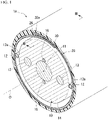
- an optical fiber cable 1A includes an inner layer cable 10 including an optical fiber, a reinforcing unit (reinforcing member) 20, an outer sheath 30, and a pair of first ripcords 12.
- the longitudinal direction of the inner layer cable 10 is simply referred to as a longitudinal direction
- the central axis of the inner layer cable 10 is referred to as a central axis O.
- a section perpendicular to the central axis O is referred to as a cross section.
- a direction that intersects the central axis O is referred to as a radial direction
- a direction that turns around the central axis O is referred to as a circumferential direction.
- the inner layer cable 10 includes a core 11 including a plurality of optical fibers, a pair of second ripcords 16, a pair of tensile strength bodies (tension members) 13, and an inner sheath 14.
- the inner layer cable 10 does not have to include the second ripcords 16.
- the core 11 extends in the longitudinal direction.
- the core 11 is configured by assembling a plurality of optical fibers.
- an optical fiber wire, an optical fiber core wire, an optical fiber tape core wire, or the like can be used as the optical fiber constituting the core 11.
- the plurality of optical fibers constituting the core 11 may be bound by a binding material in a bundled state to form an optical fiber unit.
- the plurality of optical fibers are covered with a presser roll or a water absorbing tape.
- the pair of second ripcords 16 are buried in the inner sheath 14 to sandwich the core 11 in the radial direction in a cross-sectional view.
- the pair of second ripcords 16 extend in the longitudinal direction.
- the pair of second ripcords 16 are located on a straight line passing through the central axis O perpendicular to a neutral line L described later, in a cross-sectional view.
- the pair of second ripcords 16 are in contact with the outer peripheral surface of the core 11.
- a string made of synthetic fibers such as polyester and aramid, a columnar rod made of PP or nylon, or the like can be used.
- the pair of tensile strength bodies 13 are buried in the inner sheath 14 to sandwich the core 11 in the radial direction in a cross-sectional view. Each tensile strength body 13 extends in the longitudinal direction. Each tensile strength body 13 may be disposed to be parallel to the core 11 in the longitudinal direction, or may be disposed spirally around the core 11.
- the tensile strength body 13 has a function of protecting the optical fiber of the core 11 from the tension acting on the optical fiber cable 1A.
- the material of the tensile strength body 13 is, for example, a metal wire (steel wire or the like), a tensile strength fiber (aramid fiber or the like), FRP, or the like.
- the tensile strength body 13 may be a single wire, or may be obtained by bundling or twisting a plurality of strands together.
- a straight line connecting the centers of the pair of tensile strength bodies 13 in a cross-sectional view is referred to as the neutral line L.
- the optical fiber cable 1A is bent in a direction (vertical direction in Fig. 2 ) perpendicular to the neutral line L, the expansion and contraction of the tensile strength body 13 become smaller than that when the optical fiber cable 1A is bent in the other directions. Thus, it is relatively easy to bend the optical fiber cable 1A in the direction perpendicular to the neutral line L.
- the inner layer cable 10 may include three or more tensile strength bodies 13. When three or more tensile strength bodies 13 are disposed at equal intervals in the circumferential direction, the directivity of bending the inner layer cable 10 becomes small, and thus it is possible to more easily handle the optical fiber cable 1A.
- the inner sheath 14 collectively covers the core 11, the pair of tensile strength bodies 13, and the pair of second ripcords 16.
- resin such as polyethylene (PE) or polyvinyl chloride (PVC) can be used.
- the inner sheath 14 is formed in a cylindrical shape extending in the longitudinal direction.
- the inner sheath 14 is formed by extrusion molding or the like.
- the outer sheath 30 accommodates the inner layer cable 10, the pair of first ripcords 12, and the reinforcing unit 20.
- the reinforcing unit 20 extends in the longitudinal direction and is formed in a cylindrical shape surrounding the inner layer cable 10.
- the reinforcing unit 20 includes a first adhesive film (adhesive layer) 21, a second adhesive film 22, and a reinforcing sheet 23.
- the material of the reinforcing sheet 23 metal such as iron, stainless steel, copper, or a copper alloy can be used.
- the material of the reinforcing sheet 23 can be changed as appropriate. It is desirable that the reinforcing sheet 23 be formed, for example, in a tape shape, and is provided so that a length direction is aligned with the longitudinal direction of the inner layer cable 10.
- the thickness of the reinforcing sheet 23 is, for example, about 0.1 to 0.3 mm.
- the reinforcing unit 20 will be described by using an example of a configuration including the first adhesive film 21 and the second adhesive film 22.
- the reinforcing unit 20 may include at least the first adhesive film 21.
- the second adhesive film 22 is provided in addition to the first adhesive film 21, it is possible to further strengthen a film adhesive force at an overlapping portion 20c (described later) and suppress rust on the reinforcing sheet 23.
- the reinforcing unit 20 surrounds the inner layer cable 10 over the entire circumference and is overlapped at a portion of the reinforcing member in the circumferential direction.
- a portion in which a first end portion 20a and a second end portion 20b in the circumferential direction of the reinforcing unit 20 overlap each other is referred to as an overlapping portion 20c.
- the first end portion 20a and the second end portion 20b face each other in the radial direction.
- the entirety of the overlapping portion 20c and the tensile strength body 13 are disposed at different positions in the circumferential direction.
- the first adhesive film 21 is bonded to the surface of the reinforcing sheet 23, that faces the outer sheath 30.
- the second adhesive film 22 is bonded to the surface of the reinforcing sheet 23, that faces the inner layer cable 10.
- a heat-curable type adhesive or a hot melt type adhesive can be used as the adhesive used for the first adhesive film 21 and the second adhesive film 22.
- the material of the adhesive may be changed as appropriate.
- the first adhesive film 21 has a function of fixing the outer sheath 30 to the reinforcing sheet 23.
- the second adhesive film 22 may have a function of fixing the first ripcord 12 to the reinforcing sheet 23 together with coating 12a of the first ripcord 12, which will be described later.
- a portion of the overlapping portion 20c located between the reinforcing sheets 23 in the first adhesive film 21 and the second adhesive film 22 has a function of fixing the end portions of the reinforcing sheets 23 to each other at the overlapping portion 20c.
- the reinforcing unit 20 has a corrugated shape in which peak portions 24 that are protrusions outward in the radial direction and valley portions 25 that are protrusions inward in the radial direction are alternately formed along the longitudinal direction.
- a peak portion 24a of the first end portion 20a and a peak portion 24b of the second end portion 20b are disposed to face each other in the radial direction
- a valley portion 25a of the first end portion 20a and a valley portion 25b of the second end portion 20b are disposed to face each other in the radial direction.
- the adhering state between the first end portion 20a and the second end portion 20b by the first adhesive film 21 and the second adhesive film 22 may not be uniform in the longitudinal direction.
- a state in which the first end portion 20a and the second end portion 20b are adhered to each other by the adhesive films 21 and 22 with a predetermined film adhesive force or larger is referred to as a state S1
- a state in which the first end portion 20a and the second end portion 20b are adhered to each other with a film adhesive force smaller than the predetermined film adhesive force is referred to as a state S2.
- a gap 26 is formed between the first end portion 20a and the second end portion 20b.
- the "predetermined film adhesive force" is a force as large as the first end portion 20a and the second end portion 20b are sufficiently adhered to each other by the adhesive films 21 and 22.
- a portion in the longitudinal direction is in the state S1, and the other portion is in the state S2.
- a gap 26a is formed between the peak portion 24a and the peak portion 24b, and a gap 26b is formed between the valley portion 25a and the valley portion 25b.
- the gap 26 may or may not be continuously formed in the longitudinal direction.
- the resin 30a forming the outer sheath 30 is inserted into the gap 26 between the first end portion 20a and the second end portion 20b. That is, the outer sheath 30 and the resin 30a inserted into the gap 26 are integrally formed. As shown in Fig. 3 , the resin 30a is inserted into the gap 26a between the first end portion 20a and the second end portion 20b in the peak portion 24, and the resin 30a is inserted into the gap 26b between the first end portion 20a and the second end portion 20b in the valley portion 25.
- the dimension M2 of the resin 30a between the valley portions 25a and 25b in the radial direction is thicker than the dimension M1 of the resin 30a between the peak portions 24a and 24b in the radial direction.
- a ratio W1/W2 of the resin width W1 to the overlap width W2 is equal to or more than 0.10.
- the value of W1/W2 is not particularly limited. By setting value of W1/W2 to be equal to or more than 0.10, it is possible to reliably adhere the first end portion 20a and the second end portion 20b to each other with the resin 30a.
- the outer sheath 30 is formed in a cylindrical shape extending in the longitudinal direction, and is inserted into the gap 26 as described above.
- resin such as polyethylene (PE) or polyvinyl chloride (PVC) can be used.
- the outer sheath 30 is formed of flame-retardant resin ((EVA: Ethylene Vinyl Acetate), elastomer, and the like) containing a large amount of flame-retardant filler.
- EVA Ethylene Vinyl Acetate
- the pair of first ripcords 12 extend in the longitudinal direction and are disposed between the inner layer cable 10 and the reinforcing unit 20.
- the pair of first ripcords 12 are in contact with the outer peripheral surface of the inner sheath 14.
- the pair of first ripcords 12 are in contact with the inner peripheral surface of the reinforcing unit 20, that is, the inner surface of the second adhesive film 22.
- the pair of first ripcords 12 are located on the neutral line L in the cross-sectional view.
- a string obtained by twisting synthetic fibers such as polyester and aramid can be used.
- the optical fiber cable 1A does not have to include the first ripcord 12.
- the coating 12a formed of adhesive resin is provided around the first ripcord 12.
- a polyolefin-based material such as polyethylene or a copolymer thereof (for example, EVA), thermoplastic resin such as polyester-based resin, polyurethane-based resin, or polyamide-based resin, resin having adhesiveness such as thermosetting resin, synthetic rubber, or the like can be used.
- the above materials can be singly used. In order to adjust the adhesiveness, the tackiness, the temperature at the time of heat fusion, and the like, two or more of the above materials may be mixed or modified to introduce a functional group.
- resin containing a functional group is preferably used as the material of the coating 12a in order to secure the adhesiveness between the first ripcord 12 and the reinforcing sheet 23.
- the coating 12a can be formed by applying the adhesive resin onto the outer periphery of the first ripcord 12.
- the first ripcord 12 is used in a work of tearing the reinforcing sheet 23 and the outer sheath 30 (simply referred to as a tearing work below).
- the first ripcord 12 is required to have mechanical strength (for example, tensile strength) sufficient to tear the reinforcing sheet 23 and the outer sheath 30.
- the first ripcord 12 is disposed at a position different from the position of the overlapping portion 20c of the reinforcing unit 20 in the circumferential direction in the cross-sectional view.
- the first ripcord 12 is disposed at a position at which the first ripcord overlaps the overlapping portion 20c of the reinforcing unit 20 in the circumferential direction, an operation of tearing the reinforcing unit 20 by the first ripcord 12 becomes difficult, since the thickness of the overlapping portion 20c in the radial direction is thick,.
- the first ripcord 12 since the first ripcord 12 is disposed at the position different from the position of the overlapping portion 20c of the reinforcing unit 20 in the circumferential direction, it is possible to improve the operability of tearing the reinforcing unit 20.
- a side edge 23a in the overlapping portion 20c and the first ripcord 12 are disposed at different positions in the circumferential direction in the cross-sectional view.
- the inner layer cable 10 is prepared.
- the inner layer cable 10 is obtained, for example, by feeding out the core 11 and the pair of tensile strength bodies 13 and then covering the core 11 and the pair of tensile strength bodies 13 with the inner sheath 14 (feeding).
- the inner layer cable 10 may be prepared in a separate process, or may be prepared in tandem with the subsequent process.
- the reinforcing unit 20 in which the first adhesive film 21 and the second adhesive film 22 are bonded to the flat plate-shaped reinforcing sheet 23 is prepared. Then, the flat plate-shaped reinforcing unit 20 is processed to form the peak portion 24 and the valley portion 25.
- the order of the steps of bonding the first adhesive film 21 and the second adhesive film 22 to the reinforcing sheet 23 is not limited to this, and may be changed as appropriate.
- first ripcords 12 are vertically attached to the reinforcing unit 20. At this time, the two first ripcords 12 are disposed substantially parallel to each other, and a predetermined distance is provided between the first ripcords 12.
- the reinforcing unit 20 is wound around the inner layer cable 10 to form an overlapping portion 20c in which the first end portion 20a and the second end portion 20b of the reinforcing unit 20 overlap each other at a portion of the reinforcing member in the circumferential direction (winding).
- the first end portion 20a and the second end portion 20b are temporarily fixed to each other by the first adhesive film 21 and the second adhesive film 22, and thus the reinforcing unit 20 has a cylindrical shape that surrounds the inner layer cable 10 and extends in the longitudinal direction.
- the peak portions 24 of the first end portion 20a and the second end portion 20b are caused to face each other in the radial direction, and the valley portions 25 of the first end portion 20a and the second end portion 20b are caused to face each other in the radial direction.
- the reinforcing unit 20 is pressed so that the first end portion 20a and the second end portion 20b are brought close to each other by rollers (rotating body, not shown) disposed to face each other.
- the overlapping portion 20c of the reinforcing unit 20 has a state S1 in which bonding is performed with a predetermined film adhesive force or larger, and a state S2 in which bonding is performed with a film adhesive force that does not satisfy the predetermined film adhesive force.
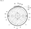
- the state S2 that does not satisfy the predetermined film adhesive force includes, for example, a state S2a shown in Fig. 4 and a state S2b shown in Fig. 5 .
- the state S2a shown in Fig. 4 the first end portion 20a and the second end portion 20b are partially in contact with each other to form a gap 26.
- the state S2b shown in Fig. 5 the first end portion 20a and the second end portion 20b are not in contact with each other, and a gap 26 is formed in the entirety in the circumferential direction of the overlapping portion 20c.
- the outer sheath 30 is extrusion-molded by using an extrusion covering device 40 as shown in Fig. 6 so as to cover the reinforcing unit 20 (performing extrusion molding).
- the extrusion covering device 40 includes a nipple 41 through which the inner layer cable 10 surrounded by the reinforcing unit 20 is inserted, and a die 42 provided substantially coaxially on the outside of the nipple 41.
- the inner layer cable 10 surrounded by the reinforcing unit 20 is inserted into an insertion hole 43 of the nipple 41, and flame-retardant resin 30a melted from a resin flow path 45 is extruded and applied onto the outer periphery of the reinforcing unit 20 coming out from an outlet 44 of the nipple 41.
- the resin pressure in the performing extrusion molding is pressure obtained in advance so that the ratio W1/W2 of the resin width W1 to the overlapping width W2 is equal to or more than 0.10.
- the resin pressure can be adjusted, for example, by changing a distance N between a tip 41a of the nipple 41 and a tip 42a of the die 42.
- the distance N that causes W1/W2 to be equal to or more than 0.10 is calculated in advance by an experiment and the like before the start of production.
- the resin pressure may be adjusted by other means.
- Other means include, for example, the shape of the die 42 and the nipple 41, the inner diameter of the resin flow path 45, the amount of the resin 30a discharged from the extrusion covering device 40, the setting of the temperature, and the like.
- the reinforcing unit 20 is covered with the resin 30a in a state where the nipple 41 and the die 42 are installed so that the distance between the nipple 41 and the die 42 is the distance N calculated in advance.
- the inner layer cable 10 and the reinforcing unit 20 are accommodated in the outer sheath 30 by extrusion-molding the outer sheath 30.
- the resin 30a is inserted into a portion (portion in the state S2) of the overlapping portion 20c, at which the first end portion 20a and the second end portion 20b are adhered to each other with a film adhesive force smaller than the predetermined film adhesive force.
- the optical fiber cable 1A shown in Fig. 2 is produced.
- Fig. 8 is a conceptual diagram showing the result of covering the reinforcing unit 20 with the resin pressure calculated in advance.
- a suppressing force for suppressing the first end portion 20a by the outer sheath 30 is applied to the overlapping portion 20c in addition to the film adhesive force.
- the outer sheath 30 provided on the outer peripheral side of the reinforcing unit 20 and the resin 30a inserted into the gap 26 are continuously formed.
- the resistance force against the force for trying to open the overlapping portion 20c when the optical fiber cable 1A is bent is the sum of the film adhesive force by the adhesive films 21 and 22 and the suppressing force by the resin 30a.
- a vertical axis in Fig. 8 indicates the resistance force
- a horizontal axis indicates the states S1, S2a, and S2b described above.
- a broken line indicates the film adhesive force before covering the outer sheath 30
- a solid line indicates the resistance force after covering the outer sheath 30 (that is, the sum of the film adhesive force and the suppressing force by the resin 30a).
- the "predetermined resistance force" in Fig. 8 refers to a threshold value of a force for suppressing an occurrence of a situation in which the overlapping portion 20c opens and the outer sheath 30 cracks when the optical fiber cable 1A is bent.
- the film adhesive force exceeds the predetermined resistance force. That is, in the state S1, the first end portion 20a and the second end portion 20b are sufficiently strongly adhered to each other by the film adhesive force of the adhesive films 21 and 22.
- the first end portion 20a and the second end portion 20b are not in contact with each other, and thus the film adhesive force is zero. Even though the first end portion 20a and the second end portion 20b are not in contact with each other, since the resin 30a of the outer sheath 30 is inserted into a gap between the first end portion 20a and the second end portion 20b, the suppressing force is applied to the overlapping portion 20c. As described above, by causing the resin 30a to exert the suppressing force, the resistance force at the portion of the state S2b is increased to the resistance force that is exceed the predetermined resistance force.
- the production method of the optical fiber cable 1A in the present embodiment includes feeding the core 11 as the inner layer cable 10 including a plurality of optical fibers, winding the reinforcing unit (reinforcing member) 20 around the core 11 to form an overlapping portion 20c in which the end portions 20a and 20b of the reinforcing unit 20 overlap each other at a portion of the reinforcing member in the circumferential direction, and performing extrusion molding of an outer sheath (sheath) 30 on the outside of the reinforcing unit 20. Then, in the performing extrusion molding, the resin 30a forming the outer sheath 30 is inserted into at least a portion of the overlapping portion 20c.
- the suppressing force is applied by inserting the resin 30a forming the outer sheath 30 into the portion of the overlapping portion 20c in the state S2 which does not satisfy the predetermined film adhesive force, and thus it is possible to increase the resistance force of such a portion.
- the resistance of the overlapping portion 20c in the longitudinal direction since it is possible to increase the resistance of the overlapping portion 20c in the longitudinal direction to be equal to or higher than a predetermined resistance force, it is possible to suppress an occurrence of a phenomenon that the overlapping portion 20c opens when the optical fiber cable 1A is bent. Therefore, it is possible to suppress the occurrence of cracking in the outer sheath 30.
- the reinforcing unit 20 has a corrugated shape in which the peak portions 24 which are protrusions outward in the radial direction and the valley portions 25 which are protrusions inward in the radial direction are alternately formed along the longitudinal direction.
- the peak portions 24 are disposed to face each other in the radial direction
- the valley portions 25 are disposed to face each other in the radial direction.
- the resin 30a forming the outer sheath 30 is formed of flame-retardant resin.
- a filler having a relatively low melting point and softening temperature is added to the resin 30a.
- the strength of the optical fiber cable 1A in a high temperature environment is lowered.
- the overlapping portion 20c opens and distortion (cracking) occurs.
- the resin 30a forming the outer sheath 30 is inserted into the overlapping portion 20c of the reinforcing unit 20, it is possible to suppress a force for opening the overlapping portion 20c even in a high temperature environment.
- the resin 30a is a flame-retardant resin, it is possible to suppress the occurrence of cracking of the outer sheath 30.
- the configuration in which the reinforcing unit 20 includes the first adhesive film 21 and the second adhesive film 22 has been described as an example.
- at least the first adhesive film 21 may be provided. Due to the absence of the second adhesive film 22, even if a portion having a low film adhesive force appears, since a suppressing force is applied to the portion having a weak film adhesive force by the resin 30a, the resistance force is increased. Therefore, it is possible to, for example, reduce the cost by omitting the second adhesive film 22.
- the entirety of the overlapping portion 20c and the tensile strength body 13 are disposed at different positions in the circumferential direction in the cross-sectional view.
- the entirety of the overlapping portion 20c and the tensile strength body 13 may be located at the same position in the circumferential direction.
- the first end portion 20a and the second end portion 20b are temporarily fixed to each other by at least the first adhesive film 21. Even when the adhesive strength of the first adhesive film 21 is insufficient, the resin 30a is inserted into the portion having a weak film adhesive force. Thus, it is possible to increase the resistance force in the longitudinal direction to a predetermined resistance force or more.
- an adhesive may be provided only on the overlapping portion 20c to temporarily fix the first end portion 20a and the second end portion 20b to each other.
- an optical fiber cable 1B in the present embodiment is different from the first embodiment in that a reinforcing unit 20A does not include the first adhesive film 21 and the second adhesive film 22. That is, the reinforcing unit (reinforcing member) 20A in the present embodiment corresponds to the reinforcing sheet 23 in the first embodiment.
- the reinforcing unit 20A does not include the first adhesive film 21 and the second adhesive film 22.
- the overlapping portion 20c is fixed or not temporarily fixed.
- the reinforcing unit 20A has a cylindrical shape that surrounds the inner layer cable 10 and extend in the longitudinal direction.
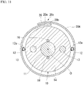
- the overlapping portion 20c of the reinforcing unit 20A may have a state S3a (not shown) in which the first end portion 20a and the second end portion 20b are in close contact with each other without a gap, a state S3b in which the first end portion 20a and the second end portion 20b are partially in contact with each other to form a gap 26 as shown in Fig. 10 , and a state S3c in which the gap 26 is formed without the first end portion 20a and the second end portion 20b being in contact with each other, as shown in Fig. 11 .
- the outer sheath 30 is extrusion-molded by using an extrusion covering device 40 as in the first embodiment so as to cover the reinforcing unit 20A.
- the relationship between the resin pressure and the adhesive strength is obtained in advance, and the distance N is calculated so that the value of W1/W2 is equal to or more than 0.10 as in the first embodiment.
- the reinforcing unit 20A is coated with the resin 30a in a state where the nipple 41 and the die 42 are installed so that the distance between the nipple 41 and the die 42 is N.
- the resin pressure is kept substantially uniform.
- the resin 30a is evenly inserted into the overlapping portion 20c in the longitudinal direction. In this manner, the resin 30a is inserted into the gap 26 in the state S3b shown in Fig. 10 , and the resin 30a is inserted into the gap 26 in the state S3c shown in Fig. 11 .
- the overlapping portion 20c in the above-described state S3a is also expanded between the first end portion 20a and the second end portion 20b by the resin pressure, and the resin 30a is inserted into the gap.
- the outer sheath 30 in which the resin 30a is inserted is formed in the overlapping portion 20c, and the optical fiber cable 1B is produced.
- the reinforcing unit 20A does not include the first adhesive film 21 and the second adhesive film 22, the suppressing force of the first end portion 20a by the outer sheath 30 becomes a resistance force against the force for trying to open the overlapping portion 20c when the optical fiber cable 1A is bent.
- the resistance force is increased to be equal to or higher than a predetermined resistance force.
- the production method of the optical fiber cable 1B in the present embodiment includes feeding the core 11 including a plurality of optical fibers, winding the reinforcing unit (reinforcing member) 20A around the core 11 to form an overlapping portion 20c in which the end portions 20a and 20b of the reinforcing unit 20A overlap each other at a portion of the reinforcing member in the circumferential direction, and performing extrusion molding of an outer sheath (sheath) 30 on the outside of the reinforcing unit 20A. Then, in the performing extrusion molding, the resin 30a forming the outer sheath 30 is inserted into the overlapping portion 20c.
- optical fiber cable 1A produced by using the production method according to the first embodiment described above was evaluated.
- the outer diameter of the inner layer cable 10 is 14.6 mm
- the length of the reinforcing unit 20 in the circumferential direction is 64 mm
- the width W2 of the overlapping portion 20c of the reinforcing unit 20 in the circumferential direction is 10 mm
- the outer diameter of the optical fiber cable 1A is 22.1 mm.
- EVA was used as the material of the outer sheath 30.
- a flame retardant for example, a filler such as a metal hydroxide (aluminum hydroxide or magnesium hydroxide) or a phosphorus-based flame retardant is added.
- base resin containing soft EVA, EEA (ethylene ethyl acrylate copolymer), and an elastomer having a relatively low melting point and softening temperature can be used.
- Table 1 shows the test results.
- the resin pressure in the performing extrusion molding is preferably pressure obtained in advance so as to satisfy W1/W2 ⁇ 0.10.
- the reinforcing unit 20 has been described as having the states S1, S2a, and S2b. However, it is not necessary to include all of these states. That is, it is possible to obtain effects as follows. If the reinforcing unit 20 includes at least one of the states S2a and S2b, it is possible to suppress the occurrence of the cracking of the outer sheath 30. In addition, the suppressing force is applied in the portion where the film adhesive force is weak in the longitudinal direction, and the resistance force is increased. Thus, it is possible to improve the reliability of the optical fiber cable 1A.
- the reinforcing unit 20 does not have to include all the states of the state S3a, the state S3b, and the state S3c, and may include at least one of the states S3a, S3b, and S3c.
- the configuration in which the peak portions 24 and the valley portions 25 are alternately formed along the longitudinal direction has been described as an example.
- the reinforcing unit 20 may not be corrugated.
- the corrugated shape of the reinforcing unit 20 is not limited to the above-described configuration.
- the corrugated shape may have a configuration in which the peak portions 24 and the valley portions 25 extending obliquely with respect to the longitudinal direction are alternately formed in the longitudinal direction.
- the reinforcing unit 20 is configured to surround the inner layer cable 10.
- the present invention is not limited to this, and the reinforcing unit 20 may surround the core 11.
- the core 11 may be fed out instead of the inner layer cable 10, and the reinforcing unit 20 may be wound around the core 11 in the winding.
- the winding is performed after forming the peak portion 24 and the valley portion 25 of the reinforcing unit 20 (20A).
- the peak portion 24 and the valley portion 25 may be formed before the performing extrusion molding after the winding is performed by using the flat sheet-shaped reinforcing unit 20 (20A).
- the dimension M2 of the resin 30a between the valley portion 25a and the valley portion 25b in the radial direction is thicker than the dimension M1 of the resin 30a between the peak portion 24a and the peak portion 24b in the radial direction.
- the present invention is not limited to this. That is, a configuration in which the dimension M2 is thinner than the dimension M1 or a configuration in which the thickness of the resin 30a is uniform between the peak portions 24 and between the valley portions 25.
- the resin 30a may be inserted into at least a gap between the valley portion 25a and the valley portion 25b between the first end portion 20a and the second end portion 20b of the overlapping portion 20c.
- the inner layer cable 10 is not limited to the above-described configuration, and may be a loose tube, a wrapping tube cable (WTC), or a slot type. Further, a tensile strength body may be buried in the outer sheath 30. Further, the plurality of optical fibers and the inner layer cable 10 may or may not be covered with a presser roll or a water absorbing tape (sheet), if necessary. Further, the present invention is not limited to the water absorbing tape (sheet), other waterproofing material or water absorbing material may or may not be provided as needed.
- the cross-sectional shape of the core 11 is circular.
- the cross-sectional shape of the core 11 may be elliptical or rectangular.
Landscapes
- Engineering & Computer Science (AREA)
- Physics & Mathematics (AREA)
- Mechanical Engineering (AREA)
- General Physics & Mathematics (AREA)
- Optics & Photonics (AREA)
- Manufacturing & Machinery (AREA)
- Light Guides In General And Applications Therefor (AREA)
- Extrusion Moulding Of Plastics Or The Like (AREA)
- Ropes Or Cables (AREA)
Abstract
Description
- The present invention relates to an optical fiber cable production method and an optical fiber cable.
- Priority is claimed on
Japanese Patent Application No. 2019-185963, filed on October 9, 2019 -
Patent Document 1 discloses an optical cable that includes an optical fiber core wire, a reinforcing member disposed to surround the optical fiber core wire, a filler with which a space between the optical fiber core wire and the reinforcing member is filled, and a sheath that covers the outside of the reinforcing member. - In a production method of such an optical cable, first, a strip-shaped material used as the reinforcing member is prepared, and an adhesive is applied onto both end portions of the strip-shaped material. Then, the optical fiber core wire is disposed above the strip-shaped material, and filling with the filler is performed on the strip-shaped material and the optical fiber core wire. Then, by causing the strip-shaped material and the optical fiber core wire to pass through a former, both the end portions of the strip-shaped material overlap each other to form the reinforcing member. Then, the reinforcing member is introduced into an extruder and is caused to pass through the extruder. In this manner, the reinforcing member is coated with a resin to form the sheath.
- [Patent Document 1]
Japanese Unexamined Patent Application, First Publication No. H11-337783 - In the optical cable in
Patent Document 1, since the overlapping portions of the reinforcing member are joined by the adhesive, there is a possibility that there is a portion having a weak adhesive force in a longitudinal direction of the optical cable. For example, at the portion having a weak adhesive force, the overlapping portion may open and stress may concentrate on the sheath covering that portion when the optical cable is bent. Accordingly, the sheath may crack. - The present invention has been made in consideration of such circumstances, and an object of the present invention is to provide an optical fiber cable production method and an optical fiber cable capable of suppressing an occurrence of cracking of a sheath.
- In order to solve the above problems, according to a first aspect of the present invention, an optical fiber cable production method includes feeding a core including a plurality of optical fibers, winding a reinforcing member around the core to form an overlapping portion at which end portions of the reinforcing member overlap each other at a portion of the reinforcing member in a circumferential direction, and performing extrusion molding of a sheath on an outside of the reinforcing member. In the performing extrusion molding, a resin forming the sheath is inserted into at least a portion of the overlapping portion.
- According to a second aspect of the present invention, an optical fiber cable includes a core including a plurality of optical fibers, a reinforcing member configured to surround the core, and a sheath configured to accommodate the core and the reinforcing member. The reinforcing member has an overlapping portion in which end portions overlap each other at a portion of the reinforcing member in a circumferential direction, and a resin forming the sheath is inserted into at least a portion of the overlapping portion.
- According to the above aspects of the present invention, it is possible to suppress an occurrence of cracking of the sheath.
-
-
Fig. 1 is a perspective view of an optical fiber cable according to a first embodiment. -
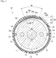
Fig. 2 is a cross-sectional view of the optical fiber cable according to the first embodiment. -
Fig. 3 is a sectional view taken along line III-III inFig. 1 . -
Fig. 4 is a cross-sectional view of the optical fiber cable inFig. 1 before covering an outer sheath. -
Fig. 5 is a cross-sectional view of the optical fiber cable inFig. 1 before covering the outer sheath. -
Fig. 6 is a diagram showing an optical fiber cable production method according to the first embodiment. -
Fig. 7 is a cross-sectional view of the optical fiber cable according to the first embodiment. -
Fig. 8 is a diagram showing a resistance force of an optical fiber cable produced by the optical fiber cable production method according to the first embodiment. -
Fig. 9 is a cross-sectional view of an optical fiber cable according to a second embodiment. -
Fig. 10 is a cross-sectional view before covering an outer sheath of the optical fiber cable according to the second embodiment. -
Fig. 11 is a cross-sectional view before covering the outer sheath of the optical fiber cable according to the second embodiment. - Hereinafter, a configuration of an optical fiber cable according to a first embodiment will be described with reference to
Figs. 1 to 8 . - As shown in
Fig. 1 , anoptical fiber cable 1A includes aninner layer cable 10 including an optical fiber, a reinforcing unit (reinforcing member) 20, anouter sheath 30, and a pair offirst ripcords 12. - Here, in the present embodiment, the longitudinal direction of the
inner layer cable 10 is simply referred to as a longitudinal direction, and the central axis of theinner layer cable 10 is referred to as a central axis O. A section perpendicular to the central axis O is referred to as a cross section. In a cross-sectional view, a direction that intersects the central axis O is referred to as a radial direction, and a direction that turns around the central axis O is referred to as a circumferential direction. - The
inner layer cable 10 includes acore 11 including a plurality of optical fibers, a pair ofsecond ripcords 16, a pair of tensile strength bodies (tension members) 13, and aninner sheath 14. Theinner layer cable 10 does not have to include thesecond ripcords 16. - The
core 11 extends in the longitudinal direction. Thecore 11 is configured by assembling a plurality of optical fibers. As the optical fiber constituting thecore 11, an optical fiber wire, an optical fiber core wire, an optical fiber tape core wire, or the like can be used. For example, the plurality of optical fibers constituting thecore 11 may be bound by a binding material in a bundled state to form an optical fiber unit. The plurality of optical fibers are covered with a presser roll or a water absorbing tape. - As shown in
Fig. 2 , the pair ofsecond ripcords 16 are buried in theinner sheath 14 to sandwich thecore 11 in the radial direction in a cross-sectional view. The pair ofsecond ripcords 16 extend in the longitudinal direction. The pair ofsecond ripcords 16 are located on a straight line passing through the central axis O perpendicular to a neutral line L described later, in a cross-sectional view. The pair ofsecond ripcords 16 are in contact with the outer peripheral surface of thecore 11. As the material of thesecond ripcord 16, a string made of synthetic fibers such as polyester and aramid, a columnar rod made of PP or nylon, or the like can be used. - The pair of
tensile strength bodies 13 are buried in theinner sheath 14 to sandwich thecore 11 in the radial direction in a cross-sectional view. Eachtensile strength body 13 extends in the longitudinal direction. Eachtensile strength body 13 may be disposed to be parallel to thecore 11 in the longitudinal direction, or may be disposed spirally around thecore 11. - The
tensile strength body 13 has a function of protecting the optical fiber of thecore 11 from the tension acting on theoptical fiber cable 1A. The material of thetensile strength body 13 is, for example, a metal wire (steel wire or the like), a tensile strength fiber (aramid fiber or the like), FRP, or the like. Thetensile strength body 13 may be a single wire, or may be obtained by bundling or twisting a plurality of strands together. - A straight line connecting the centers of the pair of
tensile strength bodies 13 in a cross-sectional view is referred to as the neutral line L. When theoptical fiber cable 1A is bent in a direction (vertical direction inFig. 2 ) perpendicular to the neutral line L, the expansion and contraction of thetensile strength body 13 become smaller than that when theoptical fiber cable 1A is bent in the other directions. Thus, it is relatively easy to bend theoptical fiber cable 1A in the direction perpendicular to the neutral line L. - The
inner layer cable 10 may include three or moretensile strength bodies 13. When three or moretensile strength bodies 13 are disposed at equal intervals in the circumferential direction, the directivity of bending theinner layer cable 10 becomes small, and thus it is possible to more easily handle theoptical fiber cable 1A. - As shown in
Fig. 2 , theinner sheath 14 collectively covers thecore 11, the pair oftensile strength bodies 13, and the pair ofsecond ripcords 16. As the material of theinner sheath 14, resin such as polyethylene (PE) or polyvinyl chloride (PVC) can be used. Theinner sheath 14 is formed in a cylindrical shape extending in the longitudinal direction. Theinner sheath 14 is formed by extrusion molding or the like. - The
outer sheath 30 accommodates theinner layer cable 10, the pair offirst ripcords 12, and the reinforcingunit 20. - The reinforcing
unit 20 extends in the longitudinal direction and is formed in a cylindrical shape surrounding theinner layer cable 10. The reinforcingunit 20 includes a first adhesive film (adhesive layer) 21, a secondadhesive film 22, and a reinforcingsheet 23. - As the material of the reinforcing
sheet 23, metal such as iron, stainless steel, copper, or a copper alloy can be used. The material of the reinforcingsheet 23 can be changed as appropriate. It is desirable that the reinforcingsheet 23 be formed, for example, in a tape shape, and is provided so that a length direction is aligned with the longitudinal direction of theinner layer cable 10. The thickness of the reinforcingsheet 23 is, for example, about 0.1 to 0.3 mm. By setting the thickness of the reinforcingsheet 23 within this range, it is possible to prevent the damage of the optical fiber of the core 11 by the feeding damage of animals, and to facilitate an operation of tearing the reinforcingsheet 23 by thefirst ripcord 12. - In the present embodiment, the reinforcing
unit 20 will be described by using an example of a configuration including the firstadhesive film 21 and the secondadhesive film 22. The reinforcingunit 20 may include at least the firstadhesive film 21. When the secondadhesive film 22 is provided in addition to the firstadhesive film 21, it is possible to further strengthen a film adhesive force at an overlappingportion 20c (described later) and suppress rust on the reinforcingsheet 23. - The reinforcing
unit 20 surrounds theinner layer cable 10 over the entire circumference and is overlapped at a portion of the reinforcing member in the circumferential direction. In the present specification, a portion in which afirst end portion 20a and asecond end portion 20b in the circumferential direction of the reinforcingunit 20 overlap each other is referred to as an overlappingportion 20c. In the overlappingportion 20c, thefirst end portion 20a and thesecond end portion 20b face each other in the radial direction. - In the present embodiment, in a cross-sectional view, the entirety of the overlapping
portion 20c and thetensile strength body 13 are disposed at different positions in the circumferential direction. - The first
adhesive film 21 is bonded to the surface of the reinforcingsheet 23, that faces theouter sheath 30. The secondadhesive film 22 is bonded to the surface of the reinforcingsheet 23, that faces theinner layer cable 10. As the adhesive used for the firstadhesive film 21 and the secondadhesive film 22, for example, a heat-curable type adhesive or a hot melt type adhesive can be used. The material of the adhesive may be changed as appropriate. The firstadhesive film 21 has a function of fixing theouter sheath 30 to the reinforcingsheet 23. The secondadhesive film 22 may have a function of fixing thefirst ripcord 12 to the reinforcingsheet 23 together withcoating 12a of thefirst ripcord 12, which will be described later. A portion of the overlappingportion 20c located between the reinforcingsheets 23 in the firstadhesive film 21 and the secondadhesive film 22 has a function of fixing the end portions of the reinforcingsheets 23 to each other at the overlappingportion 20c. - As shown in
Fig. 3 , the reinforcingunit 20 has a corrugated shape in which peakportions 24 that are protrusions outward in the radial direction andvalley portions 25 that are protrusions inward in the radial direction are alternately formed along the longitudinal direction. In the overlappingportion 20c, apeak portion 24a of thefirst end portion 20a and apeak portion 24b of thesecond end portion 20b are disposed to face each other in the radial direction, and avalley portion 25a of thefirst end portion 20a and avalley portion 25b of thesecond end portion 20b are disposed to face each other in the radial direction. - In the overlapping
portion 20c, the adhering state between thefirst end portion 20a and thesecond end portion 20b by the firstadhesive film 21 and the secondadhesive film 22 may not be uniform in the longitudinal direction. In the present specification, a state in which thefirst end portion 20a and thesecond end portion 20b are adhered to each other by theadhesive films first end portion 20a and thesecond end portion 20b are adhered to each other with a film adhesive force smaller than the predetermined film adhesive force is referred to as a state S2. In the state S2, for example, as shown inFig. 2 , agap 26 is formed between thefirst end portion 20a and thesecond end portion 20b. The "predetermined film adhesive force" is a force as large as thefirst end portion 20a and thesecond end portion 20b are sufficiently adhered to each other by theadhesive films - In the example in
Fig. 3 , a portion in the longitudinal direction is in the state S1, and the other portion is in the state S2. In the state S2, agap 26a is formed between thepeak portion 24a and thepeak portion 24b, and agap 26b is formed between thevalley portion 25a and thevalley portion 25b. Thegap 26 may or may not be continuously formed in the longitudinal direction. - Here, in the present embodiment, as shown in
Fig. 2 , theresin 30a forming theouter sheath 30 is inserted into thegap 26 between thefirst end portion 20a and thesecond end portion 20b. That is, theouter sheath 30 and theresin 30a inserted into thegap 26 are integrally formed. As shown inFig. 3 , theresin 30a is inserted into thegap 26a between thefirst end portion 20a and thesecond end portion 20b in thepeak portion 24, and theresin 30a is inserted into thegap 26b between thefirst end portion 20a and thesecond end portion 20b in thevalley portion 25. - The dimension M2 of the
resin 30a between thevalley portions resin 30a between thepeak portions - Here, in the present embodiment, as shown in
Fig. 2 , when the width of theresin 30a inserted into thegap 26 in the circumferential direction is defined as W1 and the width of the overlappingportion 20c in the circumferential direction is defined as W2, a ratio W1/W2 of the resin width W1 to the overlap width W2 is equal to or more than 0.10. The value of W1/W2 is not particularly limited. By setting value of W1/W2 to be equal to or more than 0.10, it is possible to reliably adhere thefirst end portion 20a and thesecond end portion 20b to each other with theresin 30a. - As shown in
Fig. 1 , theouter sheath 30 is formed in a cylindrical shape extending in the longitudinal direction, and is inserted into thegap 26 as described above. As the material of theouter sheath 30, resin such as polyethylene (PE) or polyvinyl chloride (PVC) can be used. In the present embodiment, theouter sheath 30 is formed of flame-retardant resin ((EVA: Ethylene Vinyl Acetate), elastomer, and the like) containing a large amount of flame-retardant filler. - As shown in
Fig. 1 , the pair offirst ripcords 12 extend in the longitudinal direction and are disposed between theinner layer cable 10 and the reinforcingunit 20. The pair offirst ripcords 12 are in contact with the outer peripheral surface of theinner sheath 14. The pair offirst ripcords 12 are in contact with the inner peripheral surface of the reinforcingunit 20, that is, the inner surface of the secondadhesive film 22. As shown inFig. 2 , the pair offirst ripcords 12 are located on the neutral line L in the cross-sectional view. As thefirst ripcord 12, a string obtained by twisting synthetic fibers such as polyester and aramid can be used. Theoptical fiber cable 1A does not have to include thefirst ripcord 12. - The
coating 12a formed of adhesive resin is provided around thefirst ripcord 12. As the material of thecoating 12a, a polyolefin-based material such as polyethylene or a copolymer thereof (for example, EVA), thermoplastic resin such as polyester-based resin, polyurethane-based resin, or polyamide-based resin, resin having adhesiveness such as thermosetting resin, synthetic rubber, or the like can be used. As thecoating 12a, the above materials can be singly used. In order to adjust the adhesiveness, the tackiness, the temperature at the time of heat fusion, and the like, two or more of the above materials may be mixed or modified to introduce a functional group. - When the reinforcing
unit 20 does not include the secondadhesive film 22, resin containing a functional group is preferably used as the material of thecoating 12a in order to secure the adhesiveness between thefirst ripcord 12 and the reinforcingsheet 23. Thecoating 12a can be formed by applying the adhesive resin onto the outer periphery of thefirst ripcord 12. - The
first ripcord 12 is used in a work of tearing the reinforcingsheet 23 and the outer sheath 30 (simply referred to as a tearing work below). Thefirst ripcord 12 is required to have mechanical strength (for example, tensile strength) sufficient to tear the reinforcingsheet 23 and theouter sheath 30. - As shown in
Fig. 2 , thefirst ripcord 12 is disposed at a position different from the position of the overlappingportion 20c of the reinforcingunit 20 in the circumferential direction in the cross-sectional view. Here, when thefirst ripcord 12 is disposed at a position at which the first ripcord overlaps the overlappingportion 20c of the reinforcingunit 20 in the circumferential direction, an operation of tearing the reinforcingunit 20 by thefirst ripcord 12 becomes difficult, since the thickness of the overlappingportion 20c in the radial direction is thick,. In the present embodiment, since thefirst ripcord 12 is disposed at the position different from the position of the overlappingportion 20c of the reinforcingunit 20 in the circumferential direction, it is possible to improve the operability of tearing the reinforcingunit 20. - Further, in the present embodiment, a
side edge 23a in the overlappingportion 20c and thefirst ripcord 12 are disposed at different positions in the circumferential direction in the cross-sectional view. Thus, when the reinforcingunit 20 is torn, it is possible to suppress the work of tearing the reinforcingunit 20 from being hindered and suppress thefirst ripcord 12 from being cut off at theside edge 23a of the overlappingportion 20c. - Next, a production method of the
optical fiber cable 1A in the present embodiment will be described. - First, the
inner layer cable 10 is prepared. Theinner layer cable 10 is obtained, for example, by feeding out thecore 11 and the pair oftensile strength bodies 13 and then covering thecore 11 and the pair oftensile strength bodies 13 with the inner sheath 14 (feeding). Theinner layer cable 10 may be prepared in a separate process, or may be prepared in tandem with the subsequent process. - Then, the reinforcing
unit 20 in which the firstadhesive film 21 and the secondadhesive film 22 are bonded to the flat plate-shaped reinforcingsheet 23 is prepared. Then, the flat plate-shaped reinforcingunit 20 is processed to form thepeak portion 24 and thevalley portion 25. The order of the steps of bonding the firstadhesive film 21 and the secondadhesive film 22 to the reinforcingsheet 23 is not limited to this, and may be changed as appropriate. - Then, two
first ripcords 12 are vertically attached to the reinforcingunit 20. At this time, the twofirst ripcords 12 are disposed substantially parallel to each other, and a predetermined distance is provided between thefirst ripcords 12. - Then, the reinforcing
unit 20 is wound around theinner layer cable 10 to form an overlappingportion 20c in which thefirst end portion 20a and thesecond end portion 20b of the reinforcingunit 20 overlap each other at a portion of the reinforcing member in the circumferential direction (winding). Thus, thefirst end portion 20a and thesecond end portion 20b are temporarily fixed to each other by the firstadhesive film 21 and the secondadhesive film 22, and thus the reinforcingunit 20 has a cylindrical shape that surrounds theinner layer cable 10 and extends in the longitudinal direction. Further, in the winding, thepeak portions 24 of thefirst end portion 20a and thesecond end portion 20b are caused to face each other in the radial direction, and thevalley portions 25 of thefirst end portion 20a and thesecond end portion 20b are caused to face each other in the radial direction. - Then, the reinforcing
unit 20 is pressed so that thefirst end portion 20a and thesecond end portion 20b are brought close to each other by rollers (rotating body, not shown) disposed to face each other. - At this time, the overlapping
portion 20c of the reinforcingunit 20 has a state S1 in which bonding is performed with a predetermined film adhesive force or larger, and a state S2 in which bonding is performed with a film adhesive force that does not satisfy the predetermined film adhesive force. - The state S2 that does not satisfy the predetermined film adhesive force includes, for example, a state S2a shown in
Fig. 4 and a state S2b shown inFig. 5 . In the state S2a shown inFig. 4 , thefirst end portion 20a and thesecond end portion 20b are partially in contact with each other to form agap 26. In the state S2b shown inFig. 5 , thefirst end portion 20a and thesecond end portion 20b are not in contact with each other, and agap 26 is formed in the entirety in the circumferential direction of the overlappingportion 20c. - Then, the
outer sheath 30 is extrusion-molded by using anextrusion covering device 40 as shown inFig. 6 so as to cover the reinforcing unit 20 (performing extrusion molding). - The
extrusion covering device 40 includes anipple 41 through which theinner layer cable 10 surrounded by the reinforcingunit 20 is inserted, and a die 42 provided substantially coaxially on the outside of thenipple 41. Theinner layer cable 10 surrounded by the reinforcingunit 20 is inserted into aninsertion hole 43 of thenipple 41, and flame-retardant resin 30a melted from aresin flow path 45 is extruded and applied onto the outer periphery of the reinforcingunit 20 coming out from anoutlet 44 of thenipple 41. - The resin pressure in the performing extrusion molding is pressure obtained in advance so that the ratio W1/W2 of the resin width W1 to the overlapping width W2 is equal to or more than 0.10. The resin pressure can be adjusted, for example, by changing a distance N between a
tip 41a of thenipple 41 and atip 42a of thedie 42. Thus, the distance N that causes W1/W2 to be equal to or more than 0.10 is calculated in advance by an experiment and the like before the start of production. The resin pressure may be adjusted by other means. Other means include, for example, the shape of thedie 42 and thenipple 41, the inner diameter of theresin flow path 45, the amount of theresin 30a discharged from theextrusion covering device 40, the setting of the temperature, and the like. - In the present embodiment, the reinforcing
unit 20 is covered with theresin 30a in a state where thenipple 41 and the die 42 are installed so that the distance between thenipple 41 and thedie 42 is the distance N calculated in advance. As described above, theinner layer cable 10 and the reinforcingunit 20 are accommodated in theouter sheath 30 by extrusion-molding theouter sheath 30. - In this manner, the
resin 30a is inserted into a portion (portion in the state S2) of the overlappingportion 20c, at which thefirst end portion 20a and thesecond end portion 20b are adhered to each other with a film adhesive force smaller than the predetermined film adhesive force. Thus, theoptical fiber cable 1A shown inFig. 2 is produced. - When a portion (portion in the state S1) of the overlapping
portions 20c at which thefirst end portion 20a and thesecond end portion 20b of the overlappingportions 20c are in close contact with each other without a gap, and are adhered to each other with a predetermined film adhesive force by theadhesive films resin 30a is not inserted into such a portion. That is, even though the resin pressure in the performing extrusion molding is uniform, there are a portion to which theresin 30a is inserted and a portion to which theresin 30a is not inserted, due to the difference in the adhesive state between thefirst end portion 20a and thesecond end portion 20b by theadhesive films - Here, the effect obtained by the present embodiment will be described with reference to
Fig. 8. Fig. 8 is a conceptual diagram showing the result of covering the reinforcingunit 20 with the resin pressure calculated in advance. In the present embodiment, by inserting theresin 30a into thegap 26, a suppressing force for suppressing thefirst end portion 20a by theouter sheath 30 is applied to the overlappingportion 20c in addition to the film adhesive force. Specifically, as shown inFigs. 2 and7 , theouter sheath 30 provided on the outer peripheral side of the reinforcingunit 20 and theresin 30a inserted into thegap 26 are continuously formed. Thus, a force of thefirst end portion 20a toward the outer peripheral side of theoptical fiber cable 1A when theoptical fiber cable 1A is bent is suppressed. Therefore, in the present embodiment, the resistance force against the force for trying to open the overlappingportion 20c when theoptical fiber cable 1A is bent is the sum of the film adhesive force by theadhesive films resin 30a. - A vertical axis in
Fig. 8 indicates the resistance force, and a horizontal axis indicates the states S1, S2a, and S2b described above. InFig. 8 , a broken line indicates the film adhesive force before covering theouter sheath 30, and a solid line indicates the resistance force after covering the outer sheath 30 (that is, the sum of the film adhesive force and the suppressing force by theresin 30a). The "predetermined resistance force" inFig. 8 refers to a threshold value of a force for suppressing an occurrence of a situation in which the overlappingportion 20c opens and theouter sheath 30 cracks when theoptical fiber cable 1A is bent. - In the state S1, as indicated by the solid line in
Fig. 8 , the film adhesive force exceeds the predetermined resistance force. That is, in the state S1, thefirst end portion 20a and thesecond end portion 20b are sufficiently strongly adhered to each other by the film adhesive force of theadhesive films - In the state S2b, the
first end portion 20a and thesecond end portion 20b are not in contact with each other, and thus the film adhesive force is zero. Even though thefirst end portion 20a and thesecond end portion 20b are not in contact with each other, since theresin 30a of theouter sheath 30 is inserted into a gap between thefirst end portion 20a and thesecond end portion 20b, the suppressing force is applied to the overlappingportion 20c. As described above, by causing theresin 30a to exert the suppressing force, the resistance force at the portion of the state S2b is increased to the resistance force that is exceed the predetermined resistance force. - In the state S2a, since the
first end portion 20a and thesecond end portion 20b are partially in contact with each other to form thegap 26, there is a film adhesive force smaller than the film adhesive force in the state S1 (broken line inFig. 8 ). By inserting theresin 30a into thegap 26, theresin 30a inserted into thegap 26 exerts the suppressing force, and thus the resistance force at the portion of the state S2b is increased to the resistance force that is exceed the predetermined resistance force. - As described above, it is understood that, in all the states S1, S2a, and S2b, the resistance force in the overlapping
portion 20c is increased to exceed the predetermined resistance force. - As described above, the production method of the
optical fiber cable 1A in the present embodiment includes feeding the core 11 as theinner layer cable 10 including a plurality of optical fibers, winding the reinforcing unit (reinforcing member) 20 around thecore 11 to form an overlappingportion 20c in which theend portions unit 20 overlap each other at a portion of the reinforcing member in the circumferential direction, and performing extrusion molding of an outer sheath (sheath) 30 on the outside of the reinforcingunit 20. Then, in the performing extrusion molding, theresin 30a forming theouter sheath 30 is inserted into at least a portion of the overlappingportion 20c. - According to such a production method, the suppressing force is applied by inserting the
resin 30a forming theouter sheath 30 into the portion of the overlappingportion 20c in the state S2 which does not satisfy the predetermined film adhesive force, and thus it is possible to increase the resistance force of such a portion. Thus, since it is possible to increase the resistance of the overlappingportion 20c in the longitudinal direction to be equal to or higher than a predetermined resistance force, it is possible to suppress an occurrence of a phenomenon that the overlappingportion 20c opens when theoptical fiber cable 1A is bent. Therefore, it is possible to suppress the occurrence of cracking in theouter sheath 30. - Further, the reinforcing
unit 20 has a corrugated shape in which thepeak portions 24 which are protrusions outward in the radial direction and thevalley portions 25 which are protrusions inward in the radial direction are alternately formed along the longitudinal direction. In the overlappingportion 20c, thepeak portions 24 are disposed to face each other in the radial direction, and thevalley portions 25 are disposed to face each other in the radial direction. With this configuration, it is possible to easily bend theoptical fiber cable 1A. Further, by forming the reinforcingunit 20 into a corrugated shape, it is possible to increase the contact area between the reinforcingunit 20 and theouter sheath 30. Thus, it is possible to increase the film adhesive force between the reinforcingunit 20 and theouter sheath 30. - In addition, the
resin 30a forming theouter sheath 30 is formed of flame-retardant resin. In the case of this configuration, a filler having a relatively low melting point and softening temperature is added to theresin 30a. Thus, it may be a problem that the strength of theoptical fiber cable 1A in a high temperature environment is lowered. In a general optical fiber cable, when the resin is flame-retardant resin, and the optical fiber cable is bent in a high temperature environment, the overlappingportion 20c opens and distortion (cracking) occurs. On the other hand, in theoptical fiber cable 1A in the present embodiment, since theresin 30a forming theouter sheath 30 is inserted into the overlappingportion 20c of the reinforcingunit 20, it is possible to suppress a force for opening the overlappingportion 20c even in a high temperature environment. Thus, even if theresin 30a is a flame-retardant resin, it is possible to suppress the occurrence of cracking of theouter sheath 30. - In the first embodiment, the configuration in which the reinforcing
unit 20 includes the firstadhesive film 21 and the secondadhesive film 22 has been described as an example. However, at least the firstadhesive film 21 may be provided. Due to the absence of the secondadhesive film 22, even if a portion having a low film adhesive force appears, since a suppressing force is applied to the portion having a weak film adhesive force by theresin 30a, the resistance force is increased. Therefore, it is possible to, for example, reduce the cost by omitting the secondadhesive film 22. - Further, the description in which the entirety of the overlapping
portion 20c and thetensile strength body 13 are disposed at different positions in the circumferential direction in the cross-sectional view. However, the entirety of the overlappingportion 20c and thetensile strength body 13 may be located at the same position in the circumferential direction. - Further, in the present embodiment, before the
first end portion 20a and thesecond end portion 20b are adhered to each other with theresin 30a of theouter sheath 30, in the winding, thefirst end portion 20a and thesecond end portion 20b are temporarily fixed to each other by at least the firstadhesive film 21. Even when the adhesive strength of the firstadhesive film 21 is insufficient, theresin 30a is inserted into the portion having a weak film adhesive force. Thus, it is possible to increase the resistance force in the longitudinal direction to a predetermined resistance force or more. When temporarily fixing thefirst end portion 20a and thesecond end portion 20b, it is not necessary to provide the firstadhesive film 21 on the entire surface of the reinforcingsheet 23. For example, an adhesive may be provided only on the overlappingportion 20c to temporarily fix thefirst end portion 20a and thesecond end portion 20b to each other. - Next, a second embodiment according to the present invention will be described. The basic configuration is the same as that in the first embodiment. Therefore, the same components are denoted by the same reference signs, the description thereof will be omitted, and only the different points will be described.
- As shown in
Fig. 9 , anoptical fiber cable 1B in the present embodiment is different from the first embodiment in that a reinforcingunit 20A does not include the firstadhesive film 21 and the secondadhesive film 22. That is, the reinforcing unit (reinforcing member) 20A in the present embodiment corresponds to the reinforcingsheet 23 in the first embodiment. - Next, a production method of the
optical fiber cable 1B in the present embodiment will be described. - In the present embodiment, the reinforcing
unit 20A does not include the firstadhesive film 21 and the secondadhesive film 22. Thus, when the reinforcingunit 20A havingpeak portions 24 andvalley portions 25 is wound around theinner layer cable 10, the overlappingportion 20c is fixed or not temporarily fixed. The reinforcingunit 20A has a cylindrical shape that surrounds theinner layer cable 10 and extend in the longitudinal direction. - At this time, in the cross-sectional view, the overlapping
portion 20c of the reinforcingunit 20A may have a state S3a (not shown) in which thefirst end portion 20a and thesecond end portion 20b are in close contact with each other without a gap, a state S3b in which thefirst end portion 20a and thesecond end portion 20b are partially in contact with each other to form agap 26 as shown inFig. 10 , and a state S3c in which thegap 26 is formed without thefirst end portion 20a and thesecond end portion 20b being in contact with each other, as shown inFig. 11 . - Then, the
outer sheath 30 is extrusion-molded by using anextrusion covering device 40 as in the first embodiment so as to cover the reinforcingunit 20A. - At this time, the relationship between the resin pressure and the adhesive strength is obtained in advance, and the distance N is calculated so that the value of W1/W2 is equal to or more than 0.10 as in the first embodiment.
- The reinforcing
unit 20A is coated with theresin 30a in a state where thenipple 41 and the die 42 are installed so that the distance between thenipple 41 and thedie 42 is N. In order to keep the outer diameter dimension of theouter sheath 30 uniform along the longitudinal direction, the resin pressure is kept substantially uniform. Thus, theresin 30a is evenly inserted into the overlappingportion 20c in the longitudinal direction. In this manner, theresin 30a is inserted into thegap 26 in the state S3b shown inFig. 10 , and theresin 30a is inserted into thegap 26 in the state S3c shown inFig. 11 . Further, the overlappingportion 20c in the above-described state S3a is also expanded between thefirst end portion 20a and thesecond end portion 20b by the resin pressure, and theresin 30a is inserted into the gap. As described above, in any of the states, as shown inFig. 9 , theouter sheath 30 in which theresin 30a is inserted is formed in the overlappingportion 20c, and theoptical fiber cable 1B is produced. - In the present embodiment, since the reinforcing
unit 20A does not include the firstadhesive film 21 and the secondadhesive film 22, the suppressing force of thefirst end portion 20a by theouter sheath 30 becomes a resistance force against the force for trying to open the overlappingportion 20c when theoptical fiber cable 1A is bent. In theoptical fiber cable 1B as well, similar to theoptical fiber cable 1A in the first embodiment, in any of the states S3a, S3b, and S3c, the resistance force is increased to be equal to or higher than a predetermined resistance force. - As described above, also in the production method of the
optical fiber cable 1B in the present embodiment includes feeding the core 11 including a plurality of optical fibers, winding the reinforcing unit (reinforcing member) 20A around thecore 11 to form an overlappingportion 20c in which theend portions unit 20A overlap each other at a portion of the reinforcing member in the circumferential direction, and performing extrusion molding of an outer sheath (sheath) 30 on the outside of the reinforcingunit 20A. Then, in the performing extrusion molding, theresin 30a forming theouter sheath 30 is inserted into the overlappingportion 20c. Thus, similar to the first embodiment, since it is possible to increase the resistance of the overlappingportion 20c in the longitudinal direction to be equal to or higher than a predetermined resistance force, it is possible to suppress an occurrence of a phenomenon that the overlappingportion 20c opens when theoptical fiber cable 1B is bent. Therefore, it is possible to suppress the occurrence of cracking in theouter sheath 30. - The above embodiments will be described below by using specific examples. The present invention is not limited to examples as follows.
- The
optical fiber cable 1A produced by using the production method according to the first embodiment described above was evaluated. - The outer diameter of the
inner layer cable 10 is 14.6 mm, the length of the reinforcingunit 20 in the circumferential direction is 64 mm, the width W2 of the overlappingportion 20c of the reinforcingunit 20 in the circumferential direction is 10 mm, and the outer diameter of theoptical fiber cable 1A is 22.1 mm. EVA was used as the material of theouter sheath 30. As a flame retardant, for example, a filler such as a metal hydroxide (aluminum hydroxide or magnesium hydroxide) or a phosphorus-based flame retardant is added. In order to add the filler such as a flame retardant, base resin containing soft EVA, EEA (ethylene ethyl acrylate copolymer), and an elastomer having a relatively low melting point and softening temperature can be used. - Under the above conditions, a plurality of samples in which the values of W1/W2 were changed by changing the distance between the
nipple 41 and the die 42 when theouter sheath 30 was extrusion-molded were prepared. After each sample was left at 70°C for 3 days, the presence or absence of cracks in theouter sheath 30 at a bending diameter cp40D (D: outer diameter of theoptical fiber cable 1A) and cp30D was examined. The above bending diameter was adopted based on the standards of various optical fiber cables. Further, the condition of leaving at 70°C for 3 days was set as a condition for allowing confirming the reliability of theouter sheath 30 based on an empirical rule. - Table 1 shows the test results.
-
[Table 1] Width W1 (mm) of resin inserted into overlapping portion Width W2 (mm) of overlapping portion W1/W2 ϕ40D ϕ30D Cracking of outer sheath 0 10 0 Y Y 0.8 10 0.08 N Y 1.0 10 0.10 N N 1.5 10 0.15 N N 2.3 10 0.23 N N - As can be understood from Table 1, when the ratio (W1/W2) of the width W1 of the
resin 30a inserted into the overlappingportion 20c to the width W2 of the overlappingportion 20c is equal to or more than 0.10, theouter sheath 30 was not cracked with any of the bending diameters ϕ40D and ϕ30D. Therefore, it was understood that, by setting the value of W1/W2 to be equal to or more than 0.10, it was possible to more reliably suppress the occurrence of cracking of theouter sheath 30. - Based on this result, the resin pressure in the performing extrusion molding is preferably pressure obtained in advance so as to satisfy W1/W2 ≥ 0.10.
- The technical scope of the present invention is not limited to the above-described embodiments, and various modifications can be made without departing from the spirit of the present invention.
- For example, in the production method in the first embodiment, the reinforcing
unit 20 has been described as having the states S1, S2a, and S2b. However, it is not necessary to include all of these states. That is, it is possible to obtain effects as follows. If the reinforcingunit 20 includes at least one of the states S2a and S2b, it is possible to suppress the occurrence of the cracking of theouter sheath 30. In addition, the suppressing force is applied in the portion where the film adhesive force is weak in the longitudinal direction, and the resistance force is increased. Thus, it is possible to improve the reliability of theoptical fiber cable 1A. Similarly, also in the production method in the second embodiment, the reinforcingunit 20 does not have to include all the states of the state S3a, the state S3b, and the state S3c, and may include at least one of the states S3a, S3b, and S3c. - Further, in the reinforcing
units peak portions 24 and thevalley portions 25 are alternately formed along the longitudinal direction has been described as an example. However, the reinforcingunit 20 may not be corrugated. Further, the corrugated shape of the reinforcingunit 20 is not limited to the above-described configuration. For example, the corrugated shape may have a configuration in which thepeak portions 24 and thevalley portions 25 extending obliquely with respect to the longitudinal direction are alternately formed in the longitudinal direction. - In the optical fiber cables in the first and second embodiments, the reinforcing
unit 20 is configured to surround theinner layer cable 10. However, the present invention is not limited to this, and the reinforcingunit 20 may surround thecore 11. In the case of this configuration, in the first and second embodiments, only the core 11 may be fed out instead of theinner layer cable 10, and the reinforcingunit 20 may be wound around thecore 11 in the winding. - Further, in the production method in the first and second embodiments, the winding is performed after forming the
peak portion 24 and thevalley portion 25 of the reinforcing unit 20 (20A). However, thepeak portion 24 and thevalley portion 25 may be formed before the performing extrusion molding after the winding is performed by using the flat sheet-shaped reinforcing unit 20 (20A). - Further, in the first and second embodiments, the dimension M2 of the
resin 30a between thevalley portion 25a and thevalley portion 25b in the radial direction is thicker than the dimension M1 of theresin 30a between thepeak portion 24a and thepeak portion 24b in the radial direction. However, the present invention is not limited to this. That is, a configuration in which the dimension M2 is thinner than the dimension M1 or a configuration in which the thickness of theresin 30a is uniform between thepeak portions 24 and between thevalley portions 25. - Further, the
resin 30a may be inserted into at least a gap between thevalley portion 25a and thevalley portion 25b between thefirst end portion 20a and thesecond end portion 20b of the overlappingportion 20c. - Further, the
inner layer cable 10 is not limited to the above-described configuration, and may be a loose tube, a wrapping tube cable (WTC), or a slot type. Further, a tensile strength body may be buried in theouter sheath 30. Further, the plurality of optical fibers and theinner layer cable 10 may or may not be covered with a presser roll or a water absorbing tape (sheet), if necessary. Further, the present invention is not limited to the water absorbing tape (sheet), other waterproofing material or water absorbing material may or may not be provided as needed. - Further, in each of the above embodiments, the cross-sectional shape of the
core 11 is circular. However, the cross-sectional shape of the core 11 may be elliptical or rectangular. -
- 1A, 1B: Optical fiber cable
- 11: Core
- 12: First ripcord
- 20, 20A: Reinforcing unit (reinforcing member)
- 20c: Overlapping portion
- 21: First adhesive film (adhesive layer)
- 24: Peak portion
- 25: Valley portion
- 30: Outer sheath (sheath)
- 30a: Resin
Claims (11)
- An optical fiber cable production method comprising:feeding a core including a plurality of optical fibers;winding a reinforcing member around the core to form an overlapping portion in which end portions of the reinforcing member overlap each other at a portion of the reinforcing member in a circumferential direction; andperforming extrusion molding of a sheath on an outside of the reinforcing member,wherein, in the performing extrusion molding, a resin forming the sheath is inserted into at least a portion of the overlapping portion.
- The optical fiber cable production method according to Claim 1, wherein
when a width of the overlapping portion in the circumferential direction is defined as W2 and a width of the resin which is inserted into the overlapping portion, in the circumferential direction, is defined as W1, W1/W2 ≥ 0.10 is satisfied. - The optical fiber cable production method according to Claim 2, wherein
a resin pressure in the performing extrusion molding is set to pressure obtained in advance so as to satisfy W1/W2 ≥ 0.10. - The optical fiber cable production method according to any one of Claims 1 to 3, wherein
in the winding, the overlapping portion is temporarily fixed with an adhesive. - An optical fiber cable comprising:a core including a plurality of optical fibers;a reinforcing member configured to surround the core; anda sheath configured to accommodate the core and the reinforcing member,wherein the reinforcing member has an overlapping portion in which end portions overlap each other at a portion of the reinforcing member in a circumferential direction, anda resin forming the sheath is inserted into at least a portion of the overlapping portion.
- The optical fiber cable according to Claim 5, whereinthe reinforcing member has a corrugated shape in which peak portions that are protrusions outward in a radial direction and valley portions that are protrusions inward in the radial direction are alternately formed along a longitudinal direction, andin the overlapping portion, the peak portions are disposed to face each other in the radial direction, and the valley portions are disposed to face each other in the radial direction.
- The optical fiber cable according to Claim 6, wherein
the resin is inserted into at least a gap between the valley portions of the overlapping portion. - The optical fiber cable according to any one of Claims 5 to 7, wherein
the sheath is formed of flame-retardant resin. - The optical fiber cable according to any one of Claims 5 to 8, wherein
when a width of the overlapping portion in the circumferential direction is defined as W2 and a width of the resin which is inserted into the overlapping portion, in the circumferential direction, is defined as W1, W1/W2 ≥ 0.10 is satisfied. - The optical fiber cable according to any one of Claims 5 to 9, further comprising:a ripcord disposed between the core and the reinforcing member,wherein the ripcord is disposed at a position different from a position of the overlapping portion in the circumferential direction in a cross-sectional view.
- The optical fiber cable according to any one of Claims 5 to 10, wherein
an adhesive layer is formed on a surface of the reinforcing member that faces the sheath.
Applications Claiming Priority (2)
| Application Number | Priority Date | Filing Date | Title |
|---|---|---|---|
| JP2019185963A JP7168540B2 (en) | 2019-10-09 | 2019-10-09 | Optical fiber cable manufacturing method and optical fiber cable |
| PCT/JP2020/030567 WO2021070466A1 (en) | 2019-10-09 | 2020-08-11 | Optical fiber cable production method, and optical fiber cable |
Publications (2)
| Publication Number | Publication Date |
|---|---|
| EP4043937A1 true EP4043937A1 (en) | 2022-08-17 |
| EP4043937A4 EP4043937A4 (en) | 2023-11-01 |
Family
ID=75380111
Family Applications (1)
| Application Number | Title | Priority Date | Filing Date |
|---|---|---|---|
| EP20875509.0A Pending EP4043937A4 (en) | 2019-10-09 | 2020-08-11 | METHOD FOR PRODUCING A FIBER CABLE AND FIBER CABLE |
Country Status (8)
| Country | Link |
|---|---|
| US (3) | US11835778B2 (en) |
| EP (1) | EP4043937A4 (en) |
| JP (1) | JP7168540B2 (en) |
| CN (2) | CN120516918A (en) |
| AU (2) | AU2020362409B2 (en) |
| CA (1) | CA3150228A1 (en) |
| TW (1) | TWI752591B (en) |
| WO (1) | WO2021070466A1 (en) |
Families Citing this family (2)
| Publication number | Priority date | Publication date | Assignee | Title |
|---|---|---|---|---|
| JP7739597B2 (en) * | 2022-03-24 | 2025-09-16 | 株式会社フジクラ | fiber optic cable |
| WO2026029098A1 (en) * | 2024-08-02 | 2026-02-05 | 住友電気工業株式会社 | Optical fiber cable and method for manufacturing optical fiber cable |
Family Cites Families (18)
| Publication number | Priority date | Publication date | Assignee | Title |
|---|---|---|---|---|
| US3087007A (en) | 1960-02-04 | 1963-04-23 | Gen Cable Corp | Electric cable and method of manufacture |
| US4151365A (en) * | 1977-08-22 | 1979-04-24 | Western Electric Company, Inc. | Filled service cable having corrugated shield and methods of making |
| US4328394A (en) * | 1981-01-14 | 1982-05-04 | Bell Telephone Laboratories, Inc. | Bonded sheath cable |
| US4439632A (en) * | 1981-01-14 | 1984-03-27 | Western Electric Co., Inc. | Bonded sheath cable |
| US4729629A (en) * | 1987-02-26 | 1988-03-08 | Sumitomo Electric Research Triangle, Inc. | Bonded sheath cable with lubricant over seam |
| US5095176A (en) * | 1990-06-12 | 1992-03-10 | At&T Bell Laboratories | Aerial metallic shielded cable having waterblocking provisions |
| DK0552530T3 (en) * | 1992-01-24 | 1996-09-16 | Alcatel Submarine Systems Bv | Underwater create noise Ring |
| US5930431A (en) * | 1997-12-31 | 1999-07-27 | Siecor Operations, Llc | Fiber optic cable |
| JPH11337783A (en) | 1998-05-27 | 1999-12-10 | Fujikura Ltd | Optical cable |
| JP5802112B2 (en) * | 2011-11-07 | 2015-10-28 | 株式会社フジクラ | Optical fiber unit manufacturing method, optical fiber unit, and optical fiber cable |
| CN102636854A (en) * | 2012-04-27 | 2012-08-15 | 江苏七宝光电集团有限公司 | Cable ointment sprayed water-blocking strip-shaped cable |
| US9482839B2 (en) | 2013-08-09 | 2016-11-01 | Corning Cable Systems Llc | Optical fiber cable with anti-split feature |
| US10126517B2 (en) * | 2014-06-10 | 2018-11-13 | Corning Optical Communications LLC | Fiber optic cable structured to facilitate accessing an end thereof |
| US9482835B2 (en) * | 2014-06-27 | 2016-11-01 | Corning Optical Communications LLC | Extreme environment optical fiber cable with crack-resistant layer |
| CN206877719U (en) | 2016-12-31 | 2018-01-12 | 无锡江南电缆有限公司 | A kind of 0.6/1 easily peelable optical fiber composite cable of kV shallow seas waterproof tensile |
| JP6851960B2 (en) * | 2017-12-21 | 2021-03-31 | 株式会社フジクラ | Fiber optic cable |
| JP7036652B2 (en) | 2018-04-06 | 2022-03-15 | トヨタ自動車株式会社 | Lithium ion secondary battery |
| US11237346B2 (en) * | 2020-03-31 | 2022-02-01 | Fujikura Ltd. | Optical fiber cable |
-
2019
- 2019-10-09 JP JP2019185963A patent/JP7168540B2/en active Active
-
2020
- 2020-08-11 CA CA3150228A patent/CA3150228A1/en active Pending
- 2020-08-11 EP EP20875509.0A patent/EP4043937A4/en active Pending
- 2020-08-11 AU AU2020362409A patent/AU2020362409B2/en active Active
- 2020-08-11 US US17/642,378 patent/US11835778B2/en active Active
- 2020-08-11 CN CN202510860258.7A patent/CN120516918A/en active Pending
- 2020-08-11 WO PCT/JP2020/030567 patent/WO2021070466A1/en not_active Ceased
- 2020-08-11 CN CN202080058684.4A patent/CN114269542B/en active Active
- 2020-08-17 TW TW109127942A patent/TWI752591B/en active
-
2023
- 2023-10-27 US US18/384,439 patent/US12298578B2/en active Active
- 2023-12-06 AU AU2023278043A patent/AU2023278043B2/en active Active
-
2025
- 2025-04-04 US US19/170,422 patent/US20250231360A1/en active Pending
Also Published As
| Publication number | Publication date |
|---|---|
| CN120516918A (en) | 2025-08-22 |
| JP2021060551A (en) | 2021-04-15 |
| TW202115448A (en) | 2021-04-16 |
| AU2020362409B2 (en) | 2023-10-12 |
| US20220326462A1 (en) | 2022-10-13 |
| AU2023278043A1 (en) | 2024-01-04 |
| CN114269542A (en) | 2022-04-01 |
| JP7168540B2 (en) | 2022-11-09 |
| US11835778B2 (en) | 2023-12-05 |
| US20250231360A1 (en) | 2025-07-17 |
| US20240053562A1 (en) | 2024-02-15 |
| TWI752591B (en) | 2022-01-11 |
| CN114269542B (en) | 2025-07-18 |
| EP4043937A4 (en) | 2023-11-01 |
| CA3150228A1 (en) | 2021-04-15 |
| AU2023278043B2 (en) | 2025-04-24 |
| US12298578B2 (en) | 2025-05-13 |
| AU2020362409A1 (en) | 2022-03-17 |
| WO2021070466A1 (en) | 2021-04-15 |
Similar Documents
| Publication | Publication Date | Title |
|---|---|---|
| US20250231360A1 (en) | Optical fiber cable production method, and optical fiber cable | |
| CN115933089B (en) | Fiber optic cable | |
| US20130108226A1 (en) | Armored cables having armor, buffer tube, and jacket access features | |
| JP6851960B2 (en) | Fiber optic cable | |
| EP0023154A1 (en) | Optical fibres cable and method of manufacturing it | |
| US12339509B2 (en) | Cable and cable reinforcement sheet | |
| TWI621888B (en) | Optical cable, optical cable manufacturing method, and optical cable dividing method | |
| JP7288778B2 (en) | Protective tube manufacturing method, cable manufacturing method, protective tube and cable | |
| EP4343400A1 (en) | Optical cable | |
| JP2016040563A (en) | Optical fiber cable and wire harness | |
| JP4383458B2 (en) | Composite cable terminal, its terminal processing method, terminal fixing method, and composite cable laying method | |
| CN116802534A (en) | fiber optic cable |
Legal Events
| Date | Code | Title | Description |
|---|---|---|---|
| STAA | Information on the status of an ep patent application or granted ep patent |
Free format text: STATUS: THE INTERNATIONAL PUBLICATION HAS BEEN MADE |
|
| PUAI | Public reference made under article 153(3) epc to a published international application that has entered the european phase |
Free format text: ORIGINAL CODE: 0009012 |
|
| STAA | Information on the status of an ep patent application or granted ep patent |
Free format text: STATUS: REQUEST FOR EXAMINATION WAS MADE |
|
| 17P | Request for examination filed |
Effective date: 20220301 |
|
| AK | Designated contracting states |
Kind code of ref document: A1 Designated state(s): AL AT BE BG CH CY CZ DE DK EE ES FI FR GB GR HR HU IE IS IT LI LT LU LV MC MK MT NL NO PL PT RO RS SE SI SK SM TR |
|
| DAV | Request for validation of the european patent (deleted) | ||
| DAX | Request for extension of the european patent (deleted) | ||
| A4 | Supplementary search report drawn up and despatched |
Effective date: 20230929 |
|
| RIC1 | Information provided on ipc code assigned before grant |
Ipc: G02B 6/44 20060101AFI20230925BHEP |
|
| STAA | Information on the status of an ep patent application or granted ep patent |
Free format text: STATUS: EXAMINATION IS IN PROGRESS |
|
| 17Q | First examination report despatched |
Effective date: 20250606 |