EP4043925A1 - Radar detection prioritization based on downstream feedback - Google Patents
Radar detection prioritization based on downstream feedback Download PDFInfo
- Publication number
- EP4043925A1 EP4043925A1 EP21212810.2A EP21212810A EP4043925A1 EP 4043925 A1 EP4043925 A1 EP 4043925A1 EP 21212810 A EP21212810 A EP 21212810A EP 4043925 A1 EP4043925 A1 EP 4043925A1
- Authority
- EP
- European Patent Office
- Prior art keywords
- detections
- radar
- processor
- radar detections
- vehicle
- Prior art date
- Legal status (The legal status is an assumption and is not a legal conclusion. Google has not performed a legal analysis and makes no representation as to the accuracy of the status listed.)
- Pending
Links
Images



Classifications
-
- G—PHYSICS
- G01—MEASURING; TESTING
- G01S—RADIO DIRECTION-FINDING; RADIO NAVIGATION; DETERMINING DISTANCE OR VELOCITY BY USE OF RADIO WAVES; LOCATING OR PRESENCE-DETECTING BY USE OF THE REFLECTION OR RERADIATION OF RADIO WAVES; ANALOGOUS ARRANGEMENTS USING OTHER WAVES
- G01S7/00—Details of systems according to groups G01S13/00, G01S15/00, G01S17/00
- G01S7/003—Transmission of data between radar, sonar or lidar systems and remote stations
-
- G—PHYSICS
- G01—MEASURING; TESTING
- G01S—RADIO DIRECTION-FINDING; RADIO NAVIGATION; DETERMINING DISTANCE OR VELOCITY BY USE OF RADIO WAVES; LOCATING OR PRESENCE-DETECTING BY USE OF THE REFLECTION OR RERADIATION OF RADIO WAVES; ANALOGOUS ARRANGEMENTS USING OTHER WAVES
- G01S7/00—Details of systems according to groups G01S13/00, G01S15/00, G01S17/00
- G01S7/02—Details of systems according to groups G01S13/00, G01S15/00, G01S17/00 of systems according to group G01S13/00
- G01S7/40—Means for monitoring or calibrating
-
- G—PHYSICS
- G01—MEASURING; TESTING
- G01S—RADIO DIRECTION-FINDING; RADIO NAVIGATION; DETERMINING DISTANCE OR VELOCITY BY USE OF RADIO WAVES; LOCATING OR PRESENCE-DETECTING BY USE OF THE REFLECTION OR RERADIATION OF RADIO WAVES; ANALOGOUS ARRANGEMENTS USING OTHER WAVES
- G01S13/00—Systems using the reflection or reradiation of radio waves, e.g. radar systems; Analogous systems using reflection or reradiation of waves whose nature or wavelength is irrelevant or unspecified
- G01S13/02—Systems using reflection of radio waves, e.g. primary radar systems; Analogous systems
- G01S13/50—Systems of measurement based on relative movement of target
- G01S13/52—Discriminating between fixed and moving objects or between objects moving at different speeds
-
- G—PHYSICS
- G01—MEASURING; TESTING
- G01S—RADIO DIRECTION-FINDING; RADIO NAVIGATION; DETERMINING DISTANCE OR VELOCITY BY USE OF RADIO WAVES; LOCATING OR PRESENCE-DETECTING BY USE OF THE REFLECTION OR RERADIATION OF RADIO WAVES; ANALOGOUS ARRANGEMENTS USING OTHER WAVES
- G01S13/00—Systems using the reflection or reradiation of radio waves, e.g. radar systems; Analogous systems using reflection or reradiation of waves whose nature or wavelength is irrelevant or unspecified
- G01S13/88—Radar or analogous systems specially adapted for specific applications
- G01S13/93—Radar or analogous systems specially adapted for specific applications for anti-collision purposes
- G01S13/931—Radar or analogous systems specially adapted for specific applications for anti-collision purposes of land vehicles
-
- G—PHYSICS
- G01—MEASURING; TESTING
- G01S—RADIO DIRECTION-FINDING; RADIO NAVIGATION; DETERMINING DISTANCE OR VELOCITY BY USE OF RADIO WAVES; LOCATING OR PRESENCE-DETECTING BY USE OF THE REFLECTION OR RERADIATION OF RADIO WAVES; ANALOGOUS ARRANGEMENTS USING OTHER WAVES
- G01S13/00—Systems using the reflection or reradiation of radio waves, e.g. radar systems; Analogous systems using reflection or reradiation of waves whose nature or wavelength is irrelevant or unspecified
- G01S13/88—Radar or analogous systems specially adapted for specific applications
- G01S13/93—Radar or analogous systems specially adapted for specific applications for anti-collision purposes
- G01S13/933—Radar or analogous systems specially adapted for specific applications for anti-collision purposes of aircraft or spacecraft
-
- G—PHYSICS
- G01—MEASURING; TESTING
- G01S—RADIO DIRECTION-FINDING; RADIO NAVIGATION; DETERMINING DISTANCE OR VELOCITY BY USE OF RADIO WAVES; LOCATING OR PRESENCE-DETECTING BY USE OF THE REFLECTION OR RERADIATION OF RADIO WAVES; ANALOGOUS ARRANGEMENTS USING OTHER WAVES
- G01S13/00—Systems using the reflection or reradiation of radio waves, e.g. radar systems; Analogous systems using reflection or reradiation of waves whose nature or wavelength is irrelevant or unspecified
- G01S13/88—Radar or analogous systems specially adapted for specific applications
- G01S13/93—Radar or analogous systems specially adapted for specific applications for anti-collision purposes
- G01S13/937—Radar or analogous systems specially adapted for specific applications for anti-collision purposes of marine craft
-
- G—PHYSICS
- G01—MEASURING; TESTING
- G01S—RADIO DIRECTION-FINDING; RADIO NAVIGATION; DETERMINING DISTANCE OR VELOCITY BY USE OF RADIO WAVES; LOCATING OR PRESENCE-DETECTING BY USE OF THE REFLECTION OR RERADIATION OF RADIO WAVES; ANALOGOUS ARRANGEMENTS USING OTHER WAVES
- G01S7/00—Details of systems according to groups G01S13/00, G01S15/00, G01S17/00
- G01S7/02—Details of systems according to groups G01S13/00, G01S15/00, G01S17/00 of systems according to group G01S13/00
- G01S7/28—Details of pulse systems
- G01S7/285—Receivers
- G01S7/295—Means for transforming co-ordinates or for evaluating data, e.g. using computers
-
- G—PHYSICS
- G08—SIGNALLING
- G08G—TRAFFIC CONTROL SYSTEMS
- G08G1/00—Traffic control systems for road vehicles
- G08G1/01—Detecting movement of traffic to be counted or controlled
-
- G—PHYSICS
- G01—MEASURING; TESTING
- G01S—RADIO DIRECTION-FINDING; RADIO NAVIGATION; DETERMINING DISTANCE OR VELOCITY BY USE OF RADIO WAVES; LOCATING OR PRESENCE-DETECTING BY USE OF THE REFLECTION OR RERADIATION OF RADIO WAVES; ANALOGOUS ARRANGEMENTS USING OTHER WAVES
- G01S13/00—Systems using the reflection or reradiation of radio waves, e.g. radar systems; Analogous systems using reflection or reradiation of waves whose nature or wavelength is irrelevant or unspecified
- G01S13/88—Radar or analogous systems specially adapted for specific applications
- G01S13/93—Radar or analogous systems specially adapted for specific applications for anti-collision purposes
- G01S13/931—Radar or analogous systems specially adapted for specific applications for anti-collision purposes of land vehicles
- G01S2013/9316—Radar or analogous systems specially adapted for specific applications for anti-collision purposes of land vehicles combined with communication equipment with other vehicles or with base stations
-
- G—PHYSICS
- G01—MEASURING; TESTING
- G01S—RADIO DIRECTION-FINDING; RADIO NAVIGATION; DETERMINING DISTANCE OR VELOCITY BY USE OF RADIO WAVES; LOCATING OR PRESENCE-DETECTING BY USE OF THE REFLECTION OR RERADIATION OF RADIO WAVES; ANALOGOUS ARRANGEMENTS USING OTHER WAVES
- G01S13/00—Systems using the reflection or reradiation of radio waves, e.g. radar systems; Analogous systems using reflection or reradiation of waves whose nature or wavelength is irrelevant or unspecified
- G01S13/88—Radar or analogous systems specially adapted for specific applications
- G01S13/93—Radar or analogous systems specially adapted for specific applications for anti-collision purposes
- G01S13/931—Radar or analogous systems specially adapted for specific applications for anti-collision purposes of land vehicles
- G01S2013/9322—Radar or analogous systems specially adapted for specific applications for anti-collision purposes of land vehicles using additional data, e.g. driver condition, road state or weather data
Definitions
- Radar is often used in vehicles to support a variety of driver assist and autonomous driving functionalities. Radar systems that are upstream of these functions produce radar detections from received radar reflections and place the detections within a buffer that is accessed by functions of a vehicle.
- the downstream functions receive the detections from the buffer and perform their respective operations.
- a radar buffer becomes saturated (e.g., full) with detections corresponding to close and large objects. Some of the objects (or portions thereof) may not be of particular importance to downstream functions. As such, the buffer may be full of unimportant detections; certain important detections may not have space within the buffer and, thus, are never processed by the downstream functions.
- certain more-meaningful detections may be processed later than they otherwise could be (e.g., because they can only be stored when space becomes available) or simply not be processed at all.
- aspects described below include a method, performed by a processor of a vehicle, of radar detection prioritization based on downstream feedback.
- the method includes receiving radar detections as the vehicle is traveling in a travel corridor, the radar detections having associated locations relative to the vehicle.
- the method further includes receiving, from another processor of the vehicle, feedback related to a downstream function executed by the other processor as the vehicle is traveling in the travel corridor and determining, based on the locations of the radar detections and the feedback related to the downstream function, whether any of the radar detections are within the travel corridor.
- the method also includes assigning a priority to the at least one of the radar detections, the priority being dependent on the locations of the at least one of the radar detections and the feedback related to the downstream function. For the at least one of the radar detections that are within the travel corridor, the method further includes storing, in a detection buffer, the at least one of the radar detections along with an indication of the assigned priority.
- aspects described below also include a system, configured to be implemented in a vehicle, for radar detection prioritization based on downstream feedback.
- the system comprises a processor and computer-readable storage media comprising instructions that, when executed by the processor, cause the processor to receive radar detections as the vehicle is traveling in a travel corridor.
- the radar detections having associated locations relative to the vehicle.
- the instructions further cause the processor to receive, from another processor of the vehicle, feedback related to a downstream function executed by the other processor as the vehicle is traveling in the travel corridor and determine, based on the locations of the radar detections and the feedback related to the downstream function, whether any of the radar detections are within the travel corridor.
- the instructions also cause the processor to, for at least one of the radar detections that are within the travel corridor, assign a priority to the at least one of the radar detections, the priority being dependent on the locations of the at least one of the radar detections and the feedback related to the downstream function.
- the instructions further cause the processor to store, in a detection buffer, the at least one of the radar detections along with an indication of the assigned priority.
- Radar is often used to support a wide variety of driver assist and autonomous driving functions. Many times, radar detections of objects (e.g., radar returns) are placed within a buffer for downstream processing. Downstream functions then pull the detections from the buffer to perform various operations. As long as there is room in the buffer, the detections can be added without issue. When the buffer is full, however, radar systems may wait until space is freed (e.g., detections are pulled by the downstream functions) prior to adding new detections.
- objects e.g., radar returns
- Downstream functions then pull the detections from the buffer to perform various operations. As long as there is room in the buffer, the detections can be added without issue. When the buffer is full, however, radar systems may wait until space is freed (e.g., detections are pulled by the downstream functions) prior to adding new detections.
- the buffer may become full of detections that are not particularly relevant to the downstream operations. For example, the buffer may become saturated with detections of an upcoming bridge even though it may not be relevant to a downstream function (e.g., speed control using a leading vehicle). As such, the buffer may be unable to store detections indicative of slow-moving traffic ahead, which may be more-relevant to the downstream operations than the bridge detections. By not influencing the storage of the detections, processing of important detections may be delayed or simply missed. This can lead to unsafe driving conditions, decreased safety, and diminished driver satisfaction.
- a downstream function e.g., speed control using a leading vehicle
- Radar detections are received as a vehicle is traveling in a travel corridor, the radar detections having associated locations relative to the vehicle.
- Feedback related to a downstream function is received from another processor as the vehicle is traveling in the travel corridor, and it is determined, based on the locations and feedback, whether any of the radar detections are within the travel corridor.
- a priority is assigned based on the locations of the at least one of the radar detections and the feedback related to the downstream function. The at least one of the radar detections are then stored in a detection buffer along with an indication of the assigned priority.
- the detection buffer may be optimized for the downstream function by filtering out certain detections and prioritizing others.
- the downstream function can process detections that matter most for driving safety and situational awareness, without being burdened evaluating less important detections. Consequently, because the downstream function's receipt of important detections is expedited, computational loads on the downstream function are reduced.
- Fig. 1 is an example illustration 100 of an environment in which radar detection prioritization based on downstream feedback may be implemented.
- the example illustration 100 shows a radar system 102 of a system (not shown) that is within a vehicle 104.
- the vehicle 104 is traveling in a travel corridor 106 that may correspond to a portion of a roadway that the vehicle 104 is traveling on.
- the travel corridor 106 may correspond to a portion of the roadway that corresponds to a same direction of travel as the vehicle 104 (e.g., one side of a roadway).
- the travel corridor 106 may be defined by extents 108 (e.g., barriers, fences, guardrails, or edges of pavement/concrete) on the lateral edges of the travel corridor 106.
- radar detections (detections 110) are received.
- the detections 110 comprise information, derived from radar reflections, about objects 112 (or portions thereof) proximate to the vehicle 104.
- detection 110-1 corresponds to object 112-1 (e.g., an overpass support)
- detection 110-2 corresponds to object 112-2 (e.g., another overpass support)
- the detection 110-3 corresponds to object 112-3 (e.g., another vehicle).
- the detections 110 have associated locations relative to the vehicle 104 and movement information.
- the detections 110 are merely representations of the respective objects 112 (or portions thereof). That is, the detections 110 themselves do not have locations or movement data; rather, the corresponding objects 112 do. For the sake of simplicity, detections 110 are used herein. For example, by stating that a detection 110 is moving, it should be understood that an object (or portion thereof) to which the detection 110 corresponds is moving.
- the radar system 102 uses feedback received from a downstream function to prioritize the detections 110. For example, the radar system 102 may use the feedback to determine which of the detections 110 are outside of the travel corridor 106. The radar system 102 may then refrain from placing those detections 110 that are outside of the travel corridor 106 into a detection buffer for processing by the downstream function. For the detections 110 that are within the travel corridor 106, the radar system 102 may prioritize the detections 110 and place them within the detection buffer for processing by the downstream function.
- the detection buffer may become full or saturated with detections 110-1 and 110-2 corresponding to the overpass because it is large and close to the vehicle.
- detection 110-3 corresponding to the other vehicle may not be able to be stored within the detection buffer.
- a detection of a moving object within the travel corridor 106 (the other vehicle) can be more important than a static object outside of the travel corridor 106 (the overpass).
- the detection buffer may be optimized for relevancy (e.g., by not storing the detections 110-1 and 110-2 while storing the detection 110-3) while reducing a computational load on the downstream function. Doing so may enable certain detections 110 to be processed earlier, leading to increased safety and driver satisfaction.
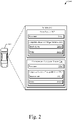
- Fig. 2 is an example illustration 200 of a system 202 in which radar detection prioritization based on downstream feedback may be implemented.
- the system 202 is configured to be disposed in the vehicle 104.
- the vehicle 104 is illustrated as a car, the vehicle 104 may comprise any vehicle (e.g., a truck, a bus, a boat, a plane, etc.) without departing from the scope of this disclosure.
- the system 202 includes the radar system 102 and an environment-perception system 204.
- the radar system 102 and the environment-perception system 204 are shown as having respective processors 206 (e.g., 206-1 and 206-2) and respective computer-readable storage media 208 (e.g., 208-1 and 208-2).
- the radar system 102 and the environment-perception system 204 may share a processor 206 and/or a computer-readable storage medium 208.
- the processors 206 execute instructions 210 (e.g., code) stored within the computer-readable storage media 208 (e.g., non-transitory storage devices such as hard drives, SSD, flash memories, read-only memories (ROM), EPROM, or EEPROM) to cause the radar system 102 and the environment-perception system 204 to perform the techniques described herein.
- instructions 210 e.g., code
- the computer-readable storage media 208 e.g., non-transitory storage devices such as hard drives, SSD, flash memories, read-only memories (ROM), EPROM, or EEPROM
- the instructions 210 cause the radar system 102 and the environment-perception system 204 to act upon (e.g., create, receive, modify, delete, transmit, or display) data 212 (e.g., application data, module data; sensor data, or I/O data). Although shown as being within the respective computer-readable storage media 208, portions of the data 212 may be within a random-access memory (RAM) or a cache (not shown) of the radar system 102 and the environment-perception system 204. Furthermore, the instructions 210 and/or the data 212 may be remote to the radar system 102 and the environment-perception system 204.
- data 212 e.g., application data, module data; sensor data, or I/O data
- RAM random-access memory
- cache not shown
- the instructions 210 and/or the data 212 may be remote to the radar system 102 and the environment-perception system 204.
- the environment-perception system 204 is configured to provide downstream feedback to the radar system 102 for radar detection prioritization.
- the radar system 102 is configured to receive the downstream feedback from the environment-perception system 204 and use it to perform radar detection prioritization.
- the radar system 102 may contain or interface with a radar sensor (not shown), and the environment-perception system 204 may contain or interface with other types of sensors (e.g., lidar, imagers, lasers, or GNSS) that are not shown.
- Fig. 3 is an example illustration 300 of radar detection prioritization based on downstream feedback.
- the example illustration 300 shows aspects of the radar system 102 and the environment-perception system 204.
- Example illustration 300 further depicts data flows between the radar system 102 and the environment-perception system 204.
- the radar system 102 contains a prioritization module 302 that receives the detections 110 and receives coefficients and constants 304 (e.g., downstream feedback) from the environment-perception system 204.
- the detections 110 are generally unfiltered, not prioritized, and may be determined by the radar system 102.
- the detections 110 have associated locations (e.g., Cartesian coordinates) relative to the vehicle 104 and velocities (e.g., range rates, relative velocities, or absolute velocities).
- the prioritization module 302 uses the locations and the coefficients and constants 304 to determine prioritized detections 306, as will be discussed further in regard to Fig. 4 .
- the prioritized detections 306 are any of the detections 110 that have been assigned a priority greater than zero.
- the prioritized detections 306 are placed, by the prioritization module 302, into a detection buffer 308.
- the detection buffer 308 may be of various structures or types, including derivatives of buffer types, depending on application. As only one example, the detection buffer 308 may function as a first-in-first-out (FIFO) buffer, and overwrite detections that are oldest, before overwriting any more-recent detections to make space.
- FIFO first-in-first-out
- the prioritization module 302 may only prioritize the detections 110 responsive to determining that the detection buffer 308 is full. For example, if there is room in the detection buffer 308, the prioritization module 302 may not prioritize the detections or place all of the detections 110 (e.g., including the prioritized detections 306 and detections 110 that have been assigned a priority of zero) into the detection buffer 308. Furthermore, the prioritization module 302 may, at 310, remove priorities from the prioritized detections 306 that are within the detection buffer 308. For example, the prioritization module 302 may occasionally (e.g., periodically or in response to a hardware or software interrupt) remove the priorities to re-establish a baseline for generating the feedback. Doing so periodically (e.g. at regular intervals) keeps the detections 110 continuous.
- the prioritization module 302 may occasionally (e.g., periodically or in response to a hardware or software interrupt) remove the priorities to re-establish a baseline for generating the feedback. Doing so periodically (e.
- the environment-perception system 204 is a downstream module (e.g., downstream function) from the radar system 102. That is, the environment-perception system 204 receives the prioritized detections 306 or pulls the prioritized detections 306 from the detection buffer 308.
- the environment-perception system 204 uses the prioritized detections 306 along with other sensor data 312 (e.g., lidar, camera, sonar, GNSS, or map data) to implement a fusion road model 314, a radar side barrier model 316, and a vision road edge model 318.
- the environment-perception system 204 may contain more models/functions than are shown/discussed herein. The non-shown models/functions may provide other functionalities that may, but do not necessarily, contribute to the coefficients and constants 304 for the prioritization of the detections 110.
- the coefficients c 1 , c 2 , and c 3 correspond to heading, curvature, and curvature rate, respectively, of the travel corridor 106, and the constant c 0 f corresponds to an extent 108 of the travel corridor 106 (e.g., an edge of a roadway).
- the radar side barrier model 316 uses the prioritized detections 306 to determine a constant c 0 r that corresponds to an extent 108 of the travel corridor 106 (e.g., a guard rail, k-rail, or fence).
- the vision road edge model 318 uses the other sensor data 312 (e.g., camera data) to determine a constant c 0 v that corresponds to an extent 108 of the travel corridor 106 (e.g., an edge of the pavement or concrete or foliage adjacent to the road).
- Two or more of the constants c 0 f , c 0 r , and c 0 v may correspond to a same extent 108.
- a location of a guardrail may be represented by two of the constants (with slight differences based on the respective models).
- the coefficients c 1 , c 2 , and c 3 and the constants c 0 f , c 0 r and c 0 v make up the coefficients and constants 304 that are fed back to the prioritization module 302 for use in prioritizing the detections 110. It should be noted that more or fewer of the described coefficients and constants 304 may be fed back or returned to the prioritization module 302. For example, not all of the constants may be available at any given time; thus, only one or two may be fed back. Furthermore, the three coefficients are indicative of a third-order polynomial representation of the travel corridor 106. In some implementations, a higher or lower order polynomial may be used. In such cases, more or fewer coefficients, respectively, would be fed back.
- the radar system 102 may store more relevant and prioritized detections (e.g., prioritized detections 306) in the detection buffer 308.
- downstream functions e.g., the environment-perception system 204 can be computationally optimized (e.g., by not acting upon every detection 110) and able to act upon relevant detections (e.g., prioritized detections 306) earlier.
- coefficients and at least one constant e.g., 4-6 numbers
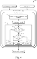
- Fig. 4 is an example illustration 400 of radar detection prioritization based on downstream feedback.
- the example illustration 400 illustrates techniques performed by the prioritization module 302 to generate the prioritized detections 306 for storing within the detection buffer 308.
- the prioritization module 302 receives the detections 110 and the coefficients and constants 304. The following is performed for each of the detections 110 (or for each of a subset of the detections 110).
- the location of the detection 110 is converted from Cartesian coordinates to Frenet coordinates 404 according to Equations 2 and 3.
- s and l are the Frenet coordinates 404 of the detection 110 (e.g., l is left-right of the vehicle 104 and s is back-front of the vehicle 104)
- x is the Cartesian coordinate of the detection 110
- the coefficients and constant c 0 f are those described above.
- the prioritization module 302 determines, at decision 408, if the detection 110 is within the travel corridor 106. Since the constants received from the environment-perception system 204 correspond to side extents of the roadway, the prioritization module 302 compares the l coordinate of the detection 110 with the constants c 0 f , c 0 r , and c 0 ⁇ . Again, not all of the constants may be received.
- the detection 110 is not within the travel corridor 106. In that case, the detection 110 is assigned a priority of zero, at 410. As such, the detection 110 does not become a prioritized detection 306.
- the process proceeds to decision 412.
- the prioritization module 302 determines if the detection 110 is moving. In order to do so, the prioritization module 302 may compare a range-rate and azimuth angle of the detection 110 with a velocity of the vehicle 104. In some implementations, the detection 110 may already have an associated relative velocity, absolute velocity, and/or direction relative to the vehicle 104. If the detection 110 already has an associated absolute velocity, for example, then the prioritization module 302 may simply determine if it is above zero (e.g., moving).
- the prioritization module 302 may assign, at 414, a priority to the detection 110 based on Equation 4.
- p c 1 ⁇ l a minor
- p is the priority of the detection 110
- C is a calibration constant
- l is the Frenet coordinate 404 of the detection 110
- a minor is a sensor limit in the l direction.
- the prioritization module 302 may assign, at 416, a priority to the detection 110 based on Equation 5.
- p A + B 1 ⁇ s 2 a major 2 + l 2 a minor 2
- s is the Frenet coordinate 404 of the detection 110
- a major is a sensor limit in the s direction.
- the prioritization module 302 may assign a priority of zero to detections 110 that are outside of the travel corridor 106, a priority based on Equation 4 to detections 110 that are within the travel corridor 106 and stationary, and a priority based on Equation 5 to detections 110 that are within the travel corridor 106 and moving.
- the detections with priorities greater than zero e.g., the prioritized detections 306
- the prioritization module 302 can filter the detections 110 (e.g., those with priorities of zero) and generate the prioritized detections 306 that get stored into the detection buffer 308 in a computationally efficient manner. Doing so enables the environment-perception system 204 to have access to an optimized detection buffer with the most relevant detections.
- Fig. 5 is an example illustration 500 of a method for radar detection prioritization based on downstream feedback.
- Example illustration 500 may be implemented utilizing the previously described examples, such as the example illustrations 100, 300, and 400 and the system 202.
- Operations 502 through 510 may be performed by one or more entities (e.g., the radar system 102 or other modules or components of the system 202).
- the order in which the operations are shown and/or described is not intended to be construed as a limitation, and any number or combination of the operations can be combined in any order to implement the method of example illustration 500 or an alternate method.
- the example illustration 500 generally starts, at 502, by a processor of a vehicle receiving radar detections as the vehicle is traveling in a travel corridor.
- the radar detections correspond to objects (or portions thereof) proximate to the vehicle as the vehicle is traveling in the travel corridor and have corresponding locations relative to the vehicle.
- the processor 206-1 of the radar system 102 may receive the detections 110 that correspond to objects 112.
- feedback related to a downstream function is received from another processor of the vehicle that is executing the downstream function as the vehicle is traveling in the travel corridor.
- the processor 206-1 of the radar system 102 may receive the coefficients and constants 304 from the processor 206-2 of the environment-perception system 204.
- the radar detections have characteristics that are indicative of their respective objects.
- the radar detections themselves may not be within the travel corridor, per se; rather, their corresponding objects (or portions thereof) may be within the travel corridor.
- the prioritization module 302 may convert coordinates of the locations, if need be (e.g., at 402), and compare the locations of the detections 110 to the constants of the coefficients and constants 304 (e.g., at 408) to determine if the respective detections 110 are within the travel corridor 106.
- a priority is assigned based on the locations and feedback. For example, the prioritization module 302 may prioritize the detections 110 that are within the travel corridor 106 at 414 if the respective detections 110 are stationary or at 416 if the respective detections 110 are moving.
- the radar detections that are within the travel corridor are stored within a detection buffer along with their respective priorities.
- the prioritization module 302 may store the prioritized detections 306 in the detection buffer 308.
- the detection buffer is optimized while reducing computational loads on the prioritization function and the downstream function. Consequently, important detections may be recognized sooner, thereby improving safety and driver satisfaction.
- Example 1 A method comprising: receiving, by a processor of a vehicle, radar detections as the vehicle is traveling in a travel corridor, the radar detections having associated locations relative to the vehicle; receiving, from another processor of the vehicle, feedback related to a downstream function executed by the other processor as the vehicle is traveling in the travel corridor; determining, based on the locations of the radar detections and the feedback related to the downstream function, whether any of the radar detections are within the travel corridor; and for at least one of the radar detections that is within the travel corridor: assigning, by the processor, a priority to the at least one of the radar detections, the priority being dependent on the locations of the at least one of the radar detections and the feedback related to the downstream function; and storing, by the processor, in a detection buffer, the at least one of the radar detections along with an indication of the assigned priority.
- Example 2 The method of example 1, further comprising: determining, by the processor, whether the at least one of the radar detections is stationary, wherein assigning the priority to the at least one of the radar detections is based further on whether the at least one of the radar detections is stationary.
- Example 3 The method of example 1 or 2, wherein assigning the priority to the at least one of the radar detections is based further on one or more radar sensor limits or one or more calibration constants.
- Example 4 The method of any preceding example, wherein the travel corridor comprises a portion of a roadway that corresponds to a direction the vehicle is traveling.
- Example 5 The method of any preceding example, further comprising, providing, by the processor, the at least one of the radar detections to the downstream function.
- Example 6 The method of any preceding example, further comprising, for at least one of the radar detections that are not within the travel corridor, refraining from storing, in the detection buffer, the at least one of the radar detections that are not within the travel corridor.
- Example 7 The method of any preceding example, further comprising removing, by the processor, the indication of the assigned priority from the at least one of the radar detections that are in the detection buffer after a predetermined time.
- Example 8 The method of any preceding example: wherein the locations are received in Cartesian coordinates; further comprising converting, by the processor, the Cartesian coordinates to Frenet coordinates based on the feedback; and wherein assigning the priority to the at least one of the radar detections is based further on the Frenet coordinates of the at least one of the radar detections.
- Example 9 The method of example 8, wherein the feedback comprises a plurality of coefficients and one or more constants.
- Example 10 The method of example 9, wherein: the plurality of coefficients correspond to a polynomial representation of the travel corridor; the one or more constants correspond to lateral offsets that define extents of the travel corridor; the coefficients are used to convert the Cartesian coordinates to the Frenet coordinates; and the constants are used to determine whether any of the radar detections are within the travel corridor.
- Example 11 A system configured to be implemented in a vehicle, the system comprising: a processor; computer-readable storage media comprising instructions that, when executed by the processor, cause the processor to: receive radar detections as the vehicle is traveling in a travel corridor, the radar detections having associated locations relative to the vehicle; receive from another processor of the vehicle, feedback related to a downstream function executed by the other processor as the vehicle is traveling in the travel corridor; determine, based on the locations of the radar detections and the feedback related to the downstream function, whether any of the radar detections are within the travel corridor; and for at least one of the radar detections that is within the travel corridor: assign a priority to the at least one of the radar detections, the priority being dependent on the locations of the at least one of the radar detections and the feedback related to the downstream function; and store, in a detection buffer, the at least one of the radar detections along with an indication of the assigned priority.
- Example 12 The system of example 11, wherein: the instructions further cause the processor to determine whether the at least one of the radar detections is stationary; and assigning the priority to the at least one of the radar detections is based further on whether the at least one of the radar detections is stationary.
- Example 13 The system of example 11 or 12, wherein assigning the priority to the at least one of the radar detections is based further on one or more radar sensor limits or one or more calibration constants.
- Example 14 The system of any of examples 11-13, wherein the travel corridor comprises a portion of a roadway that corresponds to a direction the vehicle is traveling.
- Example 15 The system of any of examples 11-14, wherein the instructions further cause the processor to provide the at least one of the radar detections to the downstream function.
- Example 16 The system of any of examples 11-15, wherein the instructions further cause the processor to, for at least one of the radar detections that are not within the travel corridor, refrain from storing, in the detection buffer, the at least one of the radar detections that is not within the travel corridor.
- Example 17 The system of any of examples 11-16, wherein the instructions further cause the processor to remove the indication of the assigned priority from the at least one of the radar detections that are in the detection buffer after a predetermined time.
- Example 18 The system of any of examples 11-17, wherein: the locations are received in Cartesian coordinates; the instructions further cause the processor to convert the Cartesian coordinates to Frenet coordinates based on the feedback; and assigning the priority to the at least one of the radar detections is based further on the Frenet coordinates of the at least one of the radar detections.
- Example 19 The system of example 18, wherein the feedback comprises a plurality of coefficients and one or more constants.
- Example 20 The system of example 19, wherein: the plurality of coefficients correspond to a polynomial representation of the travel corridor; the one or more constants correspond to lateral offsets that define extents of the travel corridor; the coefficients are used to convert the Cartesian coordinates to the Frenet coordinates; and the constants are used to determine whether any of the radar detections are within the travel corridor.
- Example 21 A system comprising means for performing any of examples 1-10.
- Example 22 A system comprising at least one processor configured to perform any of examples 1-10.
- Example 23 Computer-readable storage media comprising instructions that, when executed by at least one processor, cause the processor to perform any of examples 1-10.
- Example 24 The method of any of examples 1-10, further comprising altering a function, operation, or control of the vehicle based on the at least one of the radar detections.
Landscapes
- Engineering & Computer Science (AREA)
- Radar, Positioning & Navigation (AREA)
- Remote Sensing (AREA)
- Physics & Mathematics (AREA)
- Computer Networks & Wireless Communication (AREA)
- General Physics & Mathematics (AREA)
- Electromagnetism (AREA)
- Ocean & Marine Engineering (AREA)
- Aviation & Aerospace Engineering (AREA)
- Traffic Control Systems (AREA)
- Radar Systems Or Details Thereof (AREA)
Abstract
Description
- This application claims the benefit under 35 U.C.S. 119(e) of
U.S. Provisional Application No. 63/148,973, filed February 12, 2021 - Radar is often used in vehicles to support a variety of driver assist and autonomous driving functionalities. Radar systems that are upstream of these functions produce radar detections from received radar reflections and place the detections within a buffer that is accessed by functions of a vehicle. The downstream functions receive the detections from the buffer and perform their respective operations. Often times, a radar buffer becomes saturated (e.g., full) with detections corresponding to close and large objects. Some of the objects (or portions thereof) may not be of particular importance to downstream functions. As such, the buffer may be full of unimportant detections; certain important detections may not have space within the buffer and, thus, are never processed by the downstream functions. In addition, certain more-meaningful detections may be processed later than they otherwise could be (e.g., because they can only be stored when space becomes available) or simply not be processed at all.
- Aspects described below include a method, performed by a processor of a vehicle, of radar detection prioritization based on downstream feedback. The method includes receiving radar detections as the vehicle is traveling in a travel corridor, the radar detections having associated locations relative to the vehicle. The method further includes receiving, from another processor of the vehicle, feedback related to a downstream function executed by the other processor as the vehicle is traveling in the travel corridor and determining, based on the locations of the radar detections and the feedback related to the downstream function, whether any of the radar detections are within the travel corridor. For at least one of the radar detections that are within the travel corridor, the method also includes assigning a priority to the at least one of the radar detections, the priority being dependent on the locations of the at least one of the radar detections and the feedback related to the downstream function. For the at least one of the radar detections that are within the travel corridor, the method further includes storing, in a detection buffer, the at least one of the radar detections along with an indication of the assigned priority.
- Aspects described below also include a system, configured to be implemented in a vehicle, for radar detection prioritization based on downstream feedback. The system comprises a processor and computer-readable storage media comprising instructions that, when executed by the processor, cause the processor to receive radar detections as the vehicle is traveling in a travel corridor. The radar detections having associated locations relative to the vehicle. The instructions further cause the processor to receive, from another processor of the vehicle, feedback related to a downstream function executed by the other processor as the vehicle is traveling in the travel corridor and determine, based on the locations of the radar detections and the feedback related to the downstream function, whether any of the radar detections are within the travel corridor. The instructions also cause the processor to, for at least one of the radar detections that are within the travel corridor, assign a priority to the at least one of the radar detections, the priority being dependent on the locations of the at least one of the radar detections and the feedback related to the downstream function. The instructions further cause the processor to store, in a detection buffer, the at least one of the radar detections along with an indication of the assigned priority.
- Systems and techniques enabling radar detection prioritization based on downstream feedback are described with reference to the following drawings. The same numbers are used throughout the drawings to reference like features and components:
-
Fig. 1 is an example illustration of an environment in which radar detection prioritization based on downstream feedback may be implemented, in accordance with techniques of this disclosure; -
Fig. 2 is an example illustration of a system configured to perform radar detection prioritization based on downstream feedback, in accordance with techniques of this disclosure; -
Fig. 3 is an example illustration of radar detection prioritization based on downstream feedback, in accordance with techniques of this disclosure; -
Fig. 4 is another example illustration of radar detection prioritization based on downstream feedback, in accordance with the techniques of this disclosure; and -
Fig. 5 is an example illustration of a method of radar detection prioritization based on downstream feedback, in accordance with the techniques of this disclosure. - Radar is often used to support a wide variety of driver assist and autonomous driving functions. Many times, radar detections of objects (e.g., radar returns) are placed within a buffer for downstream processing. Downstream functions then pull the detections from the buffer to perform various operations. As long as there is room in the buffer, the detections can be added without issue. When the buffer is full, however, radar systems may wait until space is freed (e.g., detections are pulled by the downstream functions) prior to adding new detections.
- This can lead to processing of important detections being delayed or even missed. Because the storing of the detections in the buffer is uninfluenced, the buffer may become full of detections that are not particularly relevant to the downstream operations. For example, the buffer may become saturated with detections of an upcoming bridge even though it may not be relevant to a downstream function (e.g., speed control using a leading vehicle). As such, the buffer may be unable to store detections indicative of slow-moving traffic ahead, which may be more-relevant to the downstream operations than the bridge detections. By not influencing the storage of the detections, processing of important detections may be delayed or simply missed. This can lead to unsafe driving conditions, decreased safety, and diminished driver satisfaction.
- Methods and systems are described that enable radar detection prioritization based on downstream feedback. Radar detections are received as a vehicle is traveling in a travel corridor, the radar detections having associated locations relative to the vehicle. Feedback related to a downstream function is received from another processor as the vehicle is traveling in the travel corridor, and it is determined, based on the locations and feedback, whether any of the radar detections are within the travel corridor. For at least one of the radar detections that are within the travel corridor, a priority is assigned based on the locations of the at least one of the radar detections and the feedback related to the downstream function. The at least one of the radar detections are then stored in a detection buffer along with an indication of the assigned priority. In this way, the detection buffer may be optimized for the downstream function by filtering out certain detections and prioritizing others. The downstream function can process detections that matter most for driving safety and situational awareness, without being burdened evaluating less important detections. Consequently, because the downstream function's receipt of important detections is expedited, computational loads on the downstream function are reduced.
-
Fig. 1 is anexample illustration 100 of an environment in which radar detection prioritization based on downstream feedback may be implemented. Theexample illustration 100 shows aradar system 102 of a system (not shown) that is within avehicle 104. Thevehicle 104 is traveling in atravel corridor 106 that may correspond to a portion of a roadway that thevehicle 104 is traveling on. For example, thetravel corridor 106 may correspond to a portion of the roadway that corresponds to a same direction of travel as the vehicle 104 (e.g., one side of a roadway). Thetravel corridor 106 may be defined by extents 108 (e.g., barriers, fences, guardrails, or edges of pavement/concrete) on the lateral edges of thetravel corridor 106. - As the
vehicle 104 traverses through thetravel corridor 106, radar detections (detections 110) are received. Thedetections 110 comprise information, derived from radar reflections, about objects 112 (or portions thereof) proximate to thevehicle 104. For example, detection 110-1 corresponds to object 112-1 (e.g., an overpass support), detection 110-2 corresponds to object 112-2 (e.g., another overpass support), and the detection 110-3 corresponds to object 112-3 (e.g., another vehicle). Thedetections 110 have associated locations relative to thevehicle 104 and movement information. - It should be noted that the
detections 110 are merely representations of the respective objects 112 (or portions thereof). That is, thedetections 110 themselves do not have locations or movement data; rather, the corresponding objects 112 do. For the sake of simplicity,detections 110 are used herein. For example, by stating that adetection 110 is moving, it should be understood that an object (or portion thereof) to which thedetection 110 corresponds is moving. - The
radar system 102 uses feedback received from a downstream function to prioritize thedetections 110. For example, theradar system 102 may use the feedback to determine which of thedetections 110 are outside of thetravel corridor 106. Theradar system 102 may then refrain from placing thosedetections 110 that are outside of thetravel corridor 106 into a detection buffer for processing by the downstream function. For thedetections 110 that are within thetravel corridor 106, theradar system 102 may prioritize thedetections 110 and place them within the detection buffer for processing by the downstream function. - For example, in the
example illustration 100, by using conventional techniques, the detection buffer may become full or saturated with detections 110-1 and 110-2 corresponding to the overpass because it is large and close to the vehicle. In this case, detection 110-3 corresponding to the other vehicle may not be able to be stored within the detection buffer. In many cases, a detection of a moving object within the travel corridor 106 (the other vehicle) can be more important than a static object outside of the travel corridor 106 (the overpass). Thus, by using the techniques described herein, the detection buffer may be optimized for relevancy (e.g., by not storing the detections 110-1 and 110-2 while storing the detection 110-3) while reducing a computational load on the downstream function. Doing so may enablecertain detections 110 to be processed earlier, leading to increased safety and driver satisfaction. -
Fig. 2 is anexample illustration 200 of asystem 202 in which radar detection prioritization based on downstream feedback may be implemented. Thesystem 202 is configured to be disposed in thevehicle 104. Although thevehicle 104 is illustrated as a car, thevehicle 104 may comprise any vehicle (e.g., a truck, a bus, a boat, a plane, etc.) without departing from the scope of this disclosure. As shown underneath, thesystem 202 includes theradar system 102 and an environment-perception system 204. Theradar system 102 and the environment-perception system 204 are shown as having respective processors 206 (e.g., 206-1 and 206-2) and respective computer-readable storage media 208 (e.g., 208-1 and 208-2). In some implementations, theradar system 102 and the environment-perception system 204 may share a processor 206 and/or a computer-readable storage medium 208. - The processors 206 (e.g., application processors, microprocessors, digital-signal processors (DSP), or controllers) execute instructions 210 (e.g., code) stored within the computer-readable storage media 208 (e.g., non-transitory storage devices such as hard drives, SSD, flash memories, read-only memories (ROM), EPROM, or EEPROM) to cause the
radar system 102 and the environment-perception system 204 to perform the techniques described herein. - The instructions 210 cause the
radar system 102 and the environment-perception system 204 to act upon (e.g., create, receive, modify, delete, transmit, or display) data 212 (e.g., application data, module data; sensor data, or I/O data). Although shown as being within the respective computer-readable storage media 208, portions of the data 212 may be within a random-access memory (RAM) or a cache (not shown) of theradar system 102 and the environment-perception system 204. Furthermore, the instructions 210 and/or the data 212 may be remote to theradar system 102 and the environment-perception system 204. - The environment-
perception system 204 is configured to provide downstream feedback to theradar system 102 for radar detection prioritization. Theradar system 102 is configured to receive the downstream feedback from the environment-perception system 204 and use it to perform radar detection prioritization. In order to do so, theradar system 102 may contain or interface with a radar sensor (not shown), and the environment-perception system 204 may contain or interface with other types of sensors (e.g., lidar, imagers, lasers, or GNSS) that are not shown. -
Fig. 3 is anexample illustration 300 of radar detection prioritization based on downstream feedback. Theexample illustration 300 shows aspects of theradar system 102 and the environment-perception system 204.Example illustration 300 further depicts data flows between theradar system 102 and the environment-perception system 204. - The
radar system 102 contains aprioritization module 302 that receives thedetections 110 and receives coefficients and constants 304 (e.g., downstream feedback) from the environment-perception system 204. Thedetections 110 are generally unfiltered, not prioritized, and may be determined by theradar system 102. Thedetections 110 have associated locations (e.g., Cartesian coordinates) relative to thevehicle 104 and velocities (e.g., range rates, relative velocities, or absolute velocities). - The
prioritization module 302 uses the locations and the coefficients andconstants 304 to determine prioritizeddetections 306, as will be discussed further in regard toFig. 4 . The prioritizeddetections 306 are any of thedetections 110 that have been assigned a priority greater than zero. The prioritizeddetections 306 are placed, by theprioritization module 302, into adetection buffer 308. - The
detection buffer 308 may be of various structures or types, including derivatives of buffer types, depending on application. As only one example, thedetection buffer 308 may function as a first-in-first-out (FIFO) buffer, and overwrite detections that are oldest, before overwriting any more-recent detections to make space. - In some implementations, the
prioritization module 302 may only prioritize thedetections 110 responsive to determining that thedetection buffer 308 is full. For example, if there is room in thedetection buffer 308, theprioritization module 302 may not prioritize the detections or place all of the detections 110 (e.g., including the prioritizeddetections 306 anddetections 110 that have been assigned a priority of zero) into thedetection buffer 308. Furthermore, theprioritization module 302 may, at 310, remove priorities from the prioritizeddetections 306 that are within thedetection buffer 308. For example, theprioritization module 302 may occasionally (e.g., periodically or in response to a hardware or software interrupt) remove the priorities to re-establish a baseline for generating the feedback. Doing so periodically (e.g. at regular intervals) keeps thedetections 110 continuous. - The environment-
perception system 204 is a downstream module (e.g., downstream function) from theradar system 102. That is, the environment-perception system 204 receives the prioritizeddetections 306 or pulls the prioritizeddetections 306 from thedetection buffer 308. The environment-perception system 204 uses the prioritizeddetections 306 along with other sensor data 312 (e.g., lidar, camera, sonar, GNSS, or map data) to implement a fusion road model 314, a radarside barrier model 316, and a visionroad edge model 318. The environment-perception system 204 may contain more models/functions than are shown/discussed herein. The non-shown models/functions may provide other functionalities that may, but do not necessarily, contribute to the coefficients andconstants 304 for the prioritization of thedetections 110. - The fusion road model 314 uses the other sensor data 312 (e.g., map data) and/or the prioritized
detections 306 to determine a polynomial representation of thetravel corridor 106 of thevehicle 104 in Cartesian coordinates according to Equation 1:
vehicle 104 and y is back-front of thevehicle 104 while traveling along the travel corridor 106). The coefficients c 1 , c 2, and c 3 correspond to heading, curvature, and curvature rate, respectively, of thetravel corridor 106, and the constant
extent 108 of the travel corridor 106 (e.g., an edge of a roadway). - The radar
side barrier model 316 uses the prioritizeddetections 306 to determine a constant
extent 108 of the travel corridor 106 (e.g., a guard rail, k-rail, or fence). The visionroad edge model 318 uses the other sensor data 312 (e.g., camera data) to determine a constant
extent 108 of the travel corridor 106 (e.g., an edge of the pavement or concrete or foliage adjacent to the road). - Two or more of the constants


same extent 108. For example, a location of a guardrail may be represented by two of the constants (with slight differences based on the respective models). - The coefficients c 1 , c 2, and c 3 and the constants


constants 304 that are fed back to theprioritization module 302 for use in prioritizing thedetections 110. It should be noted that more or fewer of the described coefficients andconstants 304 may be fed back or returned to theprioritization module 302. For example, not all of the constants may be available at any given time; thus, only one or two may be fed back. Furthermore, the three coefficients are indicative of a third-order polynomial representation of thetravel corridor 106. In some implementations, a higher or lower order polynomial may be used. In such cases, more or fewer coefficients, respectively, would be fed back. - By using downstream feedback (e.g., the coefficients and
constants 304 from the environment-perception system 204), theradar system 102 may store more relevant and prioritized detections (e.g., prioritized detections 306) in thedetection buffer 308. In doing so, downstream functions (e.g., the environment-perception system 204) can be computationally optimized (e.g., by not acting upon every detection 110) and able to act upon relevant detections (e.g., prioritized detections 306) earlier. Furthermore, by only using coefficients and at least one constant (e.g., 4-6 numbers) as the feedback, computational and memory loads on both the environment-perception system 204 and theradar system 102 are minimized. -
Fig. 4 is anexample illustration 400 of radar detection prioritization based on downstream feedback. Theexample illustration 400 illustrates techniques performed by theprioritization module 302 to generate the prioritizeddetections 306 for storing within thedetection buffer 308. - As discussed above, the
prioritization module 302 receives thedetections 110 and the coefficients andconstants 304. The following is performed for each of the detections 110 (or for each of a subset of the detections 110). - At 402, the location of the
detection 110 is converted from Cartesian coordinates to Frenet coordinates 404 according to Equations 2 and 3.

vehicle 104 and s is back-front of the vehicle 104), x is the Cartesian coordinate of thedetection 110, and the coefficients and constant
- At 406, a priority is determined for the
detection 110. In order to do so, theprioritization module 302 determines, atdecision 408, if thedetection 110 is within thetravel corridor 106. Since the constants received from the environment-perception system 204 correspond to side extents of the roadway, theprioritization module 302 compares the l coordinate of thedetection 110 with the constants


detection 110 is not within thetravel corridor 106. In that case, thedetection 110 is assigned a priority of zero, at 410. As such, thedetection 110 does not become a prioritizeddetection 306. - If, however, it is determined at 408 that the
detection 110 is within thetravel corridor 106, the process proceeds todecision 412. At 412, theprioritization module 302 determines if thedetection 110 is moving. In order to do so, theprioritization module 302 may compare a range-rate and azimuth angle of thedetection 110 with a velocity of thevehicle 104. In some implementations, thedetection 110 may already have an associated relative velocity, absolute velocity, and/or direction relative to thevehicle 104. If thedetection 110 already has an associated absolute velocity, for example, then theprioritization module 302 may simply determine if it is above zero (e.g., moving). - If it is determined at 412 that the detection is not moving (e.g., it is stationary), then the
prioritization module 302 may assign, at 414, a priority to thedetection 110 based on Equation 4.
detection 110, C is a calibration constant, l is the Frenet coordinate 404 of thedetection 110, and aminor is a sensor limit in the l direction. - If it is determined at 412 that the
detection 110 is moving, then theprioritization module 302 may assign, at 416, a priority to thedetection 110 based on Equation 5.
detection 110, and amajor is a sensor limit in the s direction. - Accordingly, the
prioritization module 302 may assign a priority of zero todetections 110 that are outside of thetravel corridor 106, a priority based on Equation 4 todetections 110 that are within thetravel corridor 106 and stationary, and a priority based on Equation 5 todetections 110 that are within thetravel corridor 106 and moving. As stated above, the detections with priorities greater than zero (e.g., the prioritized detections 306) can then be stored within thedetection buffer 308. By using the coefficients andconstants 304, theprioritization module 302 can filter the detections 110 (e.g., those with priorities of zero) and generate the prioritizeddetections 306 that get stored into thedetection buffer 308 in a computationally efficient manner. Doing so enables the environment-perception system 204 to have access to an optimized detection buffer with the most relevant detections. -
Fig. 5 is anexample illustration 500 of a method for radar detection prioritization based on downstream feedback.Example illustration 500 may be implemented utilizing the previously described examples, such as theexample illustrations system 202.Operations 502 through 510 may be performed by one or more entities (e.g., theradar system 102 or other modules or components of the system 202). The order in which the operations are shown and/or described is not intended to be construed as a limitation, and any number or combination of the operations can be combined in any order to implement the method ofexample illustration 500 or an alternate method. - The
example illustration 500 generally starts, at 502, by a processor of a vehicle receiving radar detections as the vehicle is traveling in a travel corridor. The radar detections correspond to objects (or portions thereof) proximate to the vehicle as the vehicle is traveling in the travel corridor and have corresponding locations relative to the vehicle. For example, the processor 206-1 of theradar system 102 may receive thedetections 110 that correspond to objects 112. - At 504, feedback related to a downstream function is received from another processor of the vehicle that is executing the downstream function as the vehicle is traveling in the travel corridor. For example, the processor 206-1 of the
radar system 102 may receive the coefficients andconstants 304 from the processor 206-2 of the environment-perception system 204. - At 506, a determination is made as to whether any of the radar detections are within the travel corridor. As stated above, the radar detections have characteristics that are indicative of their respective objects. As such, the radar detections themselves may not be within the travel corridor, per se; rather, their corresponding objects (or portions thereof) may be within the travel corridor. For example, the
prioritization module 302 may convert coordinates of the locations, if need be (e.g., at 402), and compare the locations of thedetections 110 to the constants of the coefficients and constants 304 (e.g., at 408) to determine if therespective detections 110 are within thetravel corridor 106. - At 508, for the radar detections that are within the travel corridor, a priority is assigned based on the locations and feedback. For example, the
prioritization module 302 may prioritize thedetections 110 that are within thetravel corridor 106 at 414 if therespective detections 110 are stationary or at 416 if therespective detections 110 are moving. - At 510, the radar detections that are within the travel corridor are stored within a detection buffer along with their respective priorities. For example, the
prioritization module 302 may store the prioritizeddetections 306 in thedetection buffer 308. - By performing the above actions, the detection buffer is optimized while reducing computational loads on the prioritization function and the downstream function. Consequently, important detections may be recognized sooner, thereby improving safety and driver satisfaction.
- Example 1: A method comprising: receiving, by a processor of a vehicle, radar detections as the vehicle is traveling in a travel corridor, the radar detections having associated locations relative to the vehicle; receiving, from another processor of the vehicle, feedback related to a downstream function executed by the other processor as the vehicle is traveling in the travel corridor; determining, based on the locations of the radar detections and the feedback related to the downstream function, whether any of the radar detections are within the travel corridor; and for at least one of the radar detections that is within the travel corridor: assigning, by the processor, a priority to the at least one of the radar detections, the priority being dependent on the locations of the at least one of the radar detections and the feedback related to the downstream function; and storing, by the processor, in a detection buffer, the at least one of the radar detections along with an indication of the assigned priority.
- Example 2: The method of example 1, further comprising: determining, by the processor, whether the at least one of the radar detections is stationary, wherein assigning the priority to the at least one of the radar detections is based further on whether the at least one of the radar detections is stationary.
- Example 3: The method of example 1 or 2, wherein assigning the priority to the at least one of the radar detections is based further on one or more radar sensor limits or one or more calibration constants.
- Example 4: The method of any preceding example, wherein the travel corridor comprises a portion of a roadway that corresponds to a direction the vehicle is traveling.
- Example 5: The method of any preceding example, further comprising, providing, by the processor, the at least one of the radar detections to the downstream function.
- Example 6: The method of any preceding example, further comprising, for at least one of the radar detections that are not within the travel corridor, refraining from storing, in the detection buffer, the at least one of the radar detections that are not within the travel corridor.
- Example 7: The method of any preceding example, further comprising removing, by the processor, the indication of the assigned priority from the at least one of the radar detections that are in the detection buffer after a predetermined time.
- Example 8: The method of any preceding example: wherein the locations are received in Cartesian coordinates; further comprising converting, by the processor, the Cartesian coordinates to Frenet coordinates based on the feedback; and wherein assigning the priority to the at least one of the radar detections is based further on the Frenet coordinates of the at least one of the radar detections.
- Example 9: The method of example 8, wherein the feedback comprises a plurality of coefficients and one or more constants.
- Example 10: The method of example 9, wherein: the plurality of coefficients correspond to a polynomial representation of the travel corridor; the one or more constants correspond to lateral offsets that define extents of the travel corridor; the coefficients are used to convert the Cartesian coordinates to the Frenet coordinates; and the constants are used to determine whether any of the radar detections are within the travel corridor.
- Example 11: A system configured to be implemented in a vehicle, the system comprising: a processor; computer-readable storage media comprising instructions that, when executed by the processor, cause the processor to: receive radar detections as the vehicle is traveling in a travel corridor, the radar detections having associated locations relative to the vehicle; receive from another processor of the vehicle, feedback related to a downstream function executed by the other processor as the vehicle is traveling in the travel corridor; determine, based on the locations of the radar detections and the feedback related to the downstream function, whether any of the radar detections are within the travel corridor; and for at least one of the radar detections that is within the travel corridor: assign a priority to the at least one of the radar detections, the priority being dependent on the locations of the at least one of the radar detections and the feedback related to the downstream function; and store, in a detection buffer, the at least one of the radar detections along with an indication of the assigned priority.
- Example 12: The system of example 11, wherein: the instructions further cause the processor to determine whether the at least one of the radar detections is stationary; and assigning the priority to the at least one of the radar detections is based further on whether the at least one of the radar detections is stationary.
- Example 13: The system of example 11 or 12, wherein assigning the priority to the at least one of the radar detections is based further on one or more radar sensor limits or one or more calibration constants.
- Example 14: The system of any of examples 11-13, wherein the travel corridor comprises a portion of a roadway that corresponds to a direction the vehicle is traveling.
- Example 15: The system of any of examples 11-14, wherein the instructions further cause the processor to provide the at least one of the radar detections to the downstream function.
- Example 16: The system of any of examples 11-15, wherein the instructions further cause the processor to, for at least one of the radar detections that are not within the travel corridor, refrain from storing, in the detection buffer, the at least one of the radar detections that is not within the travel corridor.
- Example 17: The system of any of examples 11-16, wherein the instructions further cause the processor to remove the indication of the assigned priority from the at least one of the radar detections that are in the detection buffer after a predetermined time.
- Example 18: The system of any of examples 11-17, wherein: the locations are received in Cartesian coordinates; the instructions further cause the processor to convert the Cartesian coordinates to Frenet coordinates based on the feedback; and assigning the priority to the at least one of the radar detections is based further on the Frenet coordinates of the at least one of the radar detections.
- Example 19: The system of example 18, wherein the feedback comprises a plurality of coefficients and one or more constants.
- Example 20: The system of example 19, wherein: the plurality of coefficients correspond to a polynomial representation of the travel corridor; the one or more constants correspond to lateral offsets that define extents of the travel corridor; the coefficients are used to convert the Cartesian coordinates to the Frenet coordinates; and the constants are used to determine whether any of the radar detections are within the travel corridor.
- Example 21: A system comprising means for performing any of examples 1-10.
- Example 22: A system comprising at least one processor configured to perform any of examples 1-10.
- Example 23: Computer-readable storage media comprising instructions that, when executed by at least one processor, cause the processor to perform any of examples 1-10.
- Example 24: The method of any of examples 1-10, further comprising altering a function, operation, or control of the vehicle based on the at least one of the radar detections.
- Although implementations of radar detection prioritization based on downstream feedback have been described in language specific to certain features and/or methods, the subject of the appended claims is not necessarily limited to the specific features or methods described. Rather, the specific features and methods are disclosed as example implementations for radar detection prioritization based on downstream feedback. Further, although various examples have been described above, with each example having certain features, it should be understood that it is not necessary for a particular feature of one example to be used exclusively with that example. Instead, any of the features described above and/or depicted in the drawings can be combined with any of the examples, in addition to or in substitution for any of the other features of those examples.
Claims (15)
- A method comprising:receiving, by a processor of a vehicle, radar detections as the vehicle is traveling in a travel corridor, the radar detections having associated locations relative to the vehicle;receiving, from another processor of the vehicle, feedback related to a downstream function executed by the other processor as the vehicle is traveling in the travel corridor;determining, based on the locations of the radar detections and the feedback related to the downstream function, whether any of the radar detections are within the travel corridor; andfor at least one of the radar detections that are within the travel corridor:assigning, by the processor, a priority to the at least one of the radar detections, the priority being dependent on the locations of the at least one of the radar detections and the feedback related to the downstream function; andstoring, by the processor, in a detection buffer, the at least one of the radar detections along with an indication of the assigned priority.
- The method of claim 1, further comprising:determining, by the processor, whether the at least one of the radar detections is stationary,wherein assigning the priority to the at least one of the radar detections is based further on whether the at least one of the radar detections is stationary.
- The method of claim 1 or 2, wherein assigning the priority to the at least one of the radar detections is based further on one or more radar sensor limits or one or more calibration constants.
- The method of claim 1, 2 or 3, wherein the travel corridor comprises a portion of a roadway that corresponds to a direction the vehicle is traveling.
- The method of any preceding claim, further comprising, providing, by the processor, the at least one of the radar detections to the downstream function.
- The method of any preceding claim, further comprising, for at least one of the radar detections that are not within the travel corridor, refraining from storing, in the detection buffer, the at least one of the radar detections that are not within the travel corridor.
- The method of any preceding claim, further comprising removing, by the processor, the indication of the assigned priority from the at least one of the radar detections that are in the detection buffer after a predetermined time.
- The method of any preceding claim:wherein the locations are received in Cartesian coordinates;further comprising converting, by the processor, the Cartesian coordinates to Frenet coordinates based on the feedback; andwherein assigning the priority to the at least one of the radar detections is based further on the Frenet coordinates of the at least one of the radar detections.
- The method of any preceding claim, wherein the feedback comprises a plurality of coefficients and one or more constants.
- The method of claim 9, wherein:the plurality of coefficients corresponds to a polynomial representation of the travel corridor; andthe one or more constants correspond to lateral offsets that define extents of the travel corridor.
- The method of claim 9 or 10, wherein:the coefficients are used to convert the Cartesian coordinates to Frenet coordinates; andthe constants are used to determine whether any of the radar detections are within the travel corridor.
- The method of any preceding claim, further comprising altering a function, operation, or control of the vehicle based on the at least one of the radar detections.
- Computer-readable storage media comprising instructions that, when executed by at least one processor, cause the processor to perform the method of any one of claims 1-10.
- A system comprising at least one processor configured to perform the method of any one of claims 1-10.
- A system comprising means for performing the method of any one of claims 1-10.
Applications Claiming Priority (2)
| Application Number | Priority Date | Filing Date | Title |
|---|---|---|---|
| US202163148973P | 2021-02-12 | 2021-02-12 | |
| US17/328,845 US11754666B2 (en) | 2021-02-12 | 2021-05-24 | Radar detection prioritization based on downstream feedback |
Publications (1)
| Publication Number | Publication Date |
|---|---|
| EP4043925A1 true EP4043925A1 (en) | 2022-08-17 |
Family
ID=78827865
Family Applications (1)
| Application Number | Title | Priority Date | Filing Date |
|---|---|---|---|
| EP21212810.2A Pending EP4043925A1 (en) | 2021-02-12 | 2021-12-07 | Radar detection prioritization based on downstream feedback |
Country Status (3)
| Country | Link |
|---|---|
| US (1) | US11754666B2 (en) |
| EP (1) | EP4043925A1 (en) |
| CN (1) | CN114924238B (en) |
Families Citing this family (1)
| Publication number | Priority date | Publication date | Assignee | Title |
|---|---|---|---|---|
| GB2625324B (en) * | 2022-12-14 | 2025-02-19 | Aptiv Technologies AG | Perception sensor processing method and processing unit for performing the same |
Citations (4)
| Publication number | Priority date | Publication date | Assignee | Title |
|---|---|---|---|---|
| US20100253918A1 (en) * | 2009-04-02 | 2010-10-07 | Gm Global Technology Operations, Inc. | Infotainment display on full-windshield head-up display |
| US20150293216A1 (en) * | 2014-04-15 | 2015-10-15 | GM Global Technology Operations LLC | Method and system for detecting, tracking and estimating stationary roadside objects |
| DE102017110808A1 (en) * | 2016-06-03 | 2017-12-07 | Fujitsu Ten Limited | RADAR DEVICE AND SIGNAL PROCESSING METHOD |
| CN111401208A (en) * | 2020-03-11 | 2020-07-10 | 北京百度网讯科技有限公司 | Obstacle detection method and device, electronic equipment and storage medium |
Family Cites Families (23)
| Publication number | Priority date | Publication date | Assignee | Title |
|---|---|---|---|---|
| WO2004059900A2 (en) * | 2002-12-17 | 2004-07-15 | Evolution Robotics, Inc. | Systems and methods for visual simultaneous localization and mapping |
| US9658070B2 (en) * | 2014-07-11 | 2017-05-23 | Regents Of The University Of Minnesota | Inverse sliding-window filters for vision-aided inertial navigation systems |
| US9507346B1 (en) * | 2015-11-04 | 2016-11-29 | Zoox, Inc. | Teleoperation system and method for trajectory modification of autonomous vehicles |
| WO2018127789A1 (en) * | 2017-01-03 | 2018-07-12 | Innoviz Technologies Ltd. | Lidar systems and methods for detection and classification of objects |
| DE102017210045A1 (en) * | 2017-06-14 | 2018-12-20 | Robert Bosch Gmbh | Sensor device for an automated vehicle |
| SG11202002385QA (en) * | 2017-09-22 | 2020-04-29 | Waymo Llc | Detecting motion of an autonomous vehicle using radar technology |
| EP3707526A2 (en) * | 2017-11-06 | 2020-09-16 | Echodyne Corp | Intelligent sensor and intelligent feedback-based dynamic control of a parameter of a field of regard to which the sensor is directed |
| US10860020B2 (en) * | 2018-01-23 | 2020-12-08 | Toyota Research Institute, Inc. | System and method for adaptive perception in a vehicle |
| US10306430B1 (en) * | 2018-04-27 | 2019-05-28 | Lyft, Inc. | Vehicle-to-infrastructure communication |
| US10205457B1 (en) * | 2018-06-01 | 2019-02-12 | Yekutiel Josefsberg | RADAR target detection system for autonomous vehicles with ultra lowphase noise frequency synthesizer |
| JP7530830B2 (en) * | 2018-06-29 | 2024-08-08 | ソニーセミコンダクタソリューションズ株式会社 | Information processing device, information processing method, imaging device, computer program, information processing system, and mobile device |
| WO2020031689A1 (en) * | 2018-08-09 | 2020-02-13 | ソニーセミコンダクタソリューションズ株式会社 | Information processing device, information processing method, computer program, information processing system, and moving body device |
| WO2020070563A1 (en) * | 2018-10-01 | 2020-04-09 | Kpit Technologies Limited | Perception sensors based fusion system for vehicle control and method thereof |
| US11513214B2 (en) * | 2018-11-20 | 2022-11-29 | Metawave Corporation | Radar system for internal and external environmental detection |
| CN112286049A (en) * | 2019-07-27 | 2021-01-29 | 华为技术有限公司 | Motion trajectory prediction method and device |
| EP4034912A4 (en) * | 2019-09-24 | 2023-06-07 | INTEL Corporation | METHODS AND APPARATUS FOR MANAGING AUTOMOTIVE RADAR COORDINATION |
| US11070721B2 (en) * | 2019-09-27 | 2021-07-20 | Gm Cruise Holdings Llc | Intent-based dynamic change of compute resources of vehicle perception system |
| US11037000B2 (en) * | 2019-09-27 | 2021-06-15 | Gm Cruise Holdings Llc | Intent-based dynamic change of resolution and region of interest of vehicle perception system |
| US11408995B2 (en) * | 2020-02-24 | 2022-08-09 | Aptiv Technologies Limited | Lateral-bin monitoring for radar target detection |
| US11753006B2 (en) * | 2020-06-08 | 2023-09-12 | Robert Bosch Gmbh | Representing objects in a surrounding environment of a vehicle using a frenet coordinate system |
| US11550325B2 (en) * | 2020-06-10 | 2023-01-10 | Nvidia Corp. | Adversarial scenarios for safety testing of autonomous vehicles |
| CN111522350B (en) * | 2020-07-06 | 2020-10-09 | 深圳裹动智驾科技有限公司 | Sensing method, intelligent control equipment and automatic driving vehicle |
| US11926343B2 (en) * | 2020-07-20 | 2024-03-12 | Tusimple, Inc. | Classification and prioritization of objects for autonomous driving |
-
2021
- 2021-05-24 US US17/328,845 patent/US11754666B2/en active Active
- 2021-12-07 EP EP21212810.2A patent/EP4043925A1/en active Pending
- 2021-12-29 CN CN202111640035.8A patent/CN114924238B/en active Active
Patent Citations (5)
| Publication number | Priority date | Publication date | Assignee | Title |
|---|---|---|---|---|
| US20100253918A1 (en) * | 2009-04-02 | 2010-10-07 | Gm Global Technology Operations, Inc. | Infotainment display on full-windshield head-up display |
| US20150293216A1 (en) * | 2014-04-15 | 2015-10-15 | GM Global Technology Operations LLC | Method and system for detecting, tracking and estimating stationary roadside objects |
| DE102017110808A1 (en) * | 2016-06-03 | 2017-12-07 | Fujitsu Ten Limited | RADAR DEVICE AND SIGNAL PROCESSING METHOD |
| CN111401208A (en) * | 2020-03-11 | 2020-07-10 | 北京百度网讯科技有限公司 | Obstacle detection method and device, electronic equipment and storage medium |
| EP3879307A1 (en) * | 2020-03-11 | 2021-09-15 | Beijing Baidu Netcom Science And Technology Co., Ltd. | Method and apparatus for detecting obstacle |
Non-Patent Citations (1)
| Title |
|---|
| FELIX KUNZ ET AL: "Fast Collision Checking with a Frenet Obstacle Grid for Motion Planning", 10. WORKSHOP FAHRERASSISTENZSYSTEME - FAS 2015, 28 September 2015 (2015-09-28), Walting im Altmühltal, pages 95 - 104, XP055725440, ISBN: 978-3-00-050746-5 * |
Also Published As
| Publication number | Publication date |
|---|---|
| CN114924238A (en) | 2022-08-19 |
| US20220260670A1 (en) | 2022-08-18 |
| CN114924238B (en) | 2025-11-25 |
| US11754666B2 (en) | 2023-09-12 |
Similar Documents
| Publication | Publication Date | Title |
|---|---|---|
| CN111284493B (en) | Device and method for controlling the travel of a vehicle | |
| US11692848B2 (en) | Map information system | |
| EP3683782B1 (en) | Method for assisting a driver, driver assistance system, and vehicle including such driver assistance system | |
| US11597385B2 (en) | Autonomous vehicle and vehicle running control method using the same | |
| EP2599072B1 (en) | Traffic control system, vehicle control system, traffic regulation system, and traffic control method | |
| EP1913452B1 (en) | Method for recognizing a turning process, and driver assistance system for motor vehicles | |
| US9779624B2 (en) | Method and system of driving assistance for collision avoidance | |
| EP3486132B1 (en) | Vehicle control device | |
| EP3106836A1 (en) | A unit and method for adjusting a road boundary | |
| DE112009004844T5 (en) | VEHICLE MONITORING DEVICE ENVIRONMENT | |
| EP3527450B1 (en) | Vehicle control apparatus | |
| US20220009496A1 (en) | Vehicle control device, vehicle control method, and non-transitory computer-readable medium | |
| EP3549837A1 (en) | Vehicle control apparatus | |
| CN117657216A (en) | Speed planning method, device and equipment for automatic driving vehicle and vehicle | |
| US20250206317A1 (en) | Vehicle control device and vehicle control method | |
| US11754666B2 (en) | Radar detection prioritization based on downstream feedback | |
| DE102010029637B4 (en) | Method for object tracking in a positioning system and positioning system | |
| CN118560524A (en) | Vehicle merging processing method, device, electronic device and autonomous driving vehicle | |
| JP2020165689A (en) | Support devices, support programs, and support methods | |
| EP3364211A1 (en) | Method and device for detecting a possible collision, and vehicle | |
| US12131645B1 (en) | Methods for lane changing decision for vehicles on expressways considering safety risks in a networked environment | |
| EP4596341A2 (en) | Active safety control method and apparatus for vehicle traveling, medium, and device | |
| EP4711233A1 (en) | Obstacle detection assitance system and obstacle detection assistance method | |
| CN121180243A (en) | Safety Assurance Approach for Resilient End-to-End Automated Driving Systems | |
| CN120096591A (en) | Cut-in intention prediction method, probabilistic intention reasoning model training method and device |
Legal Events
| Date | Code | Title | Description |
|---|---|---|---|
| PUAI | Public reference made under article 153(3) epc to a published international application that has entered the european phase |
Free format text: ORIGINAL CODE: 0009012 |
|
| STAA | Information on the status of an ep patent application or granted ep patent |
Free format text: STATUS: THE APPLICATION HAS BEEN PUBLISHED |
|
| AK | Designated contracting states |
Kind code of ref document: A1 Designated state(s): AL AT BE BG CH CY CZ DE DK EE ES FI FR GB GR HR HU IE IS IT LI LT LU LV MC MK MT NL NO PL PT RO RS SE SI SK SM TR |
|
| STAA | Information on the status of an ep patent application or granted ep patent |
Free format text: STATUS: REQUEST FOR EXAMINATION WAS MADE |
|
| 17P | Request for examination filed |
Effective date: 20221208 |
|
| RBV | Designated contracting states (corrected) |
Designated state(s): AL AT BE BG CH CY CZ DE DK EE ES FI FR GB GR HR HU IE IS IT LI LT LU LV MC MK MT NL NO PL PT RO RS SE SI SK SM TR |
|
| RAP1 | Party data changed (applicant data changed or rights of an application transferred) |
Owner name: APTIV TECHNOLOGIES AG |
|
| RAP3 | Party data changed (applicant data changed or rights of an application transferred) |
Owner name: APTIV TECHNOLOGIES AG |
|
| STAA | Information on the status of an ep patent application or granted ep patent |
Free format text: STATUS: EXAMINATION IS IN PROGRESS |
|
| 17Q | First examination report despatched |
Effective date: 20241211 |