EP4043824A1 - Trigger for a weapons replica - Google Patents
Trigger for a weapons replica Download PDFInfo
- Publication number
- EP4043824A1 EP4043824A1 EP21204356.6A EP21204356A EP4043824A1 EP 4043824 A1 EP4043824 A1 EP 4043824A1 EP 21204356 A EP21204356 A EP 21204356A EP 4043824 A1 EP4043824 A1 EP 4043824A1
- Authority
- EP
- European Patent Office
- Prior art keywords
- trigger
- frame
- rotation
- axis
- arm
- Prior art date
- Legal status (The legal status is an assumption and is not a legal conclusion. Google has not performed a legal analysis and makes no representation as to the accuracy of the status listed.)
- Granted
Links
Images


Classifications
-
- F—MECHANICAL ENGINEERING; LIGHTING; HEATING; WEAPONS; BLASTING
- F41—WEAPONS
- F41A—FUNCTIONAL FEATURES OR DETAILS COMMON TO BOTH SMALLARMS AND ORDNANCE, e.g. CANNONS; MOUNTINGS FOR SMALLARMS OR ORDNANCE
- F41A19/00—Firing or trigger mechanisms; Cocking mechanisms
- F41A19/58—Electric firing mechanisms
- F41A19/69—Electric contacts or switches peculiar thereto
-
- F—MECHANICAL ENGINEERING; LIGHTING; HEATING; WEAPONS; BLASTING
- F41—WEAPONS
- F41A—FUNCTIONAL FEATURES OR DETAILS COMMON TO BOTH SMALLARMS AND ORDNANCE, e.g. CANNONS; MOUNTINGS FOR SMALLARMS OR ORDNANCE
- F41A19/00—Firing or trigger mechanisms; Cocking mechanisms
- F41A19/06—Mechanical firing mechanisms, e.g. counterrecoil firing, recoil actuated firing mechanisms
- F41A19/10—Triggers; Trigger mountings
Definitions
- the subject of the invention is a trigger that improves the sensitivity of detecting a trigger press in gun replicas, in particular ASG with electronic circuits using optical sensors to detect the position of the trigger.
- Airsoft guns are usually faithful copies of original firearms made in a 1:1 scale and shoot pellets using compressed gas. They are used in airsoft games, training, military simulations, and its users pay attention not only to how accurately the external appearance has been copied, but also expect them to act in a way that best imitates the operation of a real firearm.
- AEG Automatic electric guns
- the motor is controlled by closing the contacts of the power circuit when the trigger is pressed, which is a mechanical element consisting of one or two parts working together.
- the trigger movement causes direct pressure on the moving part of the trigger switch, and then the sliding moving part causes the contacts to close in the trigger switch and the motor power circuit is closed.
- High pressure air guns are a variant of ASGs driven by compressed air.
- the trigger movement is analogous, with the difference that the pressure is exerted on the electronic microswitch. Pressing the trigger activates the solenoid valve, which supplies the appropriate dose of compressed air to the chamber.
- the operation of the trigger in well-known AEG and HPA replicas has several basic disadvantages such as: no possibility to configure the sensitivity of the trigger individually to the user's needs, burning contacts in trigger switches of AEG replicas due to the current flowing in the circuit and the resulting malfunction of the weapon, low resistance of microswitches to mechanical damage and limited number of short- circuit cycles and contacts opening.
- triggers that might be used in AEG and HPA replicas are available on the market and compatible with electronic systems having optical sensors detecting the position of the trigger. Some of them are made of aluminum or metal alloy and have the trigger blades in different shapes and colors.
- Utility model application W. 128319 disclose a trigger position detection system having printed circuit board comprising a light source and a light receiver, wherein the circuit board is located on the internal surface of a one half of the replicas frame.
- the Light sources active surface and the light receiver are directed torwards the opposite half of the replicas frame, and the trigger blocks the light emitted by the source.
- Patent application PL234505B1 disclose a trigger position detection system in replica firearms comprising a sensor built from at least one light source and at least one receiver converting the light signal into an electrical signal, wherein the light source and the light receiver are located on a printed circuit board in a way that they are deviated from the vertical axes running perpendicularly to the upper surface of the cylinder edge by an angle from the range of 0° - 90°, and their active surfaces are directed towards the replica trigger.
- European Patent application EP3367041 describes a system for shooting a weapon that includes an activating module able to be coupled to an actuating module of a weapon, said activating module actuates the actuating module and shoots the weapon.
- the activating module comprises a controller, an emitter and a receiver both optically coupled, where the controller detects an interruption of the beam of light received in the receiver previously emitted by the emitter and for generating, in response to said interruption, a trigger signal to actuate the actuating module and shoot the weapon.
- a trigger for a gun replica bearing in the axis of rotation in both frame halves is attached with a spring around the axis of rotation.
- the essence of the solution according to the present invention is that the obscuring surface on the inner surface of the long arm of the angle bracket is a reflecting surface.
- the bracket is situated with a long arm perpendicular to the axis of rotation of the trigger and with the short arm facing toward the printed circuit board. The short arms length is less than the distance between the printed circuit board and the opposite half of the frame.
- the reflecting surface in the release position of the trigger blade only covers the projection of the transmitter. When the trigger blade is moved to the fully depressed position, it simultaneously covers the projection of the transmitter and receiver of the reflected light and the resulting signal of the opto-electrical sensor is processed in the board's electronic layout and activates the ball projectile shot assembly.
- the trigger has a support at the level of the axis of rotation.
- the support is projecting in the opposite direction to the position of the angle bracket and in the release position of the trigger blade the support is resting its lower surface on the halves of the frame or on only one half of the frame being pressed by a torsion spring mounted with a coil placed on a pin.
- the pin is led out on both sides in the axis of rotation of the trigger.
- the bent end of one arm of the spring is inserted into the longitudinal hole in the support.
- the second, opposing arm of the spring rests on the frame on the side under the angle bracket.
- the long arm of the bracket has a two-step recess along the bottom edge.
- the long arm of the bracket has a cut upper corner on the side opposite to the short arm.
- the trigger is made of metal and has a polished reflective surface.
- the reflecting surface of the trigger is covered with a light reflecting layer, made especially of silver, aluminum, foil or reflective paint.
- the main advantage of the solution described above is a significant increase in the precision of trigger movement detection by increasing the sensitivity thresholds that can be set by the user by up to 500% compared to standard triggers.
- the use of the trigger eliminates the need for additional stickers or paints reflecting the light emitted by the trigger sensor, glued onto the structural elements of the replica's skeleton.
- Another advantage of using the trigger is the independence of the trigger sensor operation from the structural elements of the replica's skeleton because the trigger surface is the direct reflecting element.
- the trigger according to the invention replaces the standard trigger used in replicas.
- Fig. 1 is a vertical section of the replica
- Fig. 2 vertical section of the replica within the trigger unit with the released trigger
- Fig. 5 shows the position of the pressed trigger in with reference to photoelements of the trigger sensor located on the PCB
- Fig. 6 - a half-sectional view of the trigger embedded in both halves of the replica frame.
- the exemplary trigger system for the replica comprises the following elements built inside the connected frame halves 3a and 3b of the body in the handle or stock:
- Upper part of the trigger 1 has a form of an angle bracket 13, with a long arm 13x and a short arm 13y, wherein the long arm 13x is perpendicular to the axis rotation O of the trigger 1 and the inner surface of the long arm 13x is a reflecting surface 14, reflecting light emitted by the light emitter 21.
- the short arm 13y faces towards the electronic circuit board 2, the length of the short arm 13y is being smaller than the distance B between this board 2 and the frame half 3a opposite thereto.
- the reflecting surface 14 has such dimensions where in the release position of the trigger 11, it covers only the projection of the transmitter 21, while when the trigger 11 is moved to the fully depressed b position, it simultaneously covers the projections of the transmitter 21 and the reflected light receiver 22.
- the resulting optoelectric sensor signal 21, 22 processed in the electronic circuit of the plate 2 activates the ball missile firing unit.
- the trigger 1 has a support 15 protruding in the opposite direction to the position of the angle bracket 13.
- the support 15 in the released position and the trigger blade 11 rests with its lower surface against both halves of the frame 3a, 3b or only by half of the frame 3b under the pressure of a torsion spring 16 embedded with a coil on the pin 12 brought out on both sides in the axis of rotation O of the trigger 1.
- the bent end of one arm of the torsion spring 16 is inserted into the longitudinal hole 17 in the bracket 15 of the trigger 1, while the other, opposing arm of the torsion spring 16 rests against the inside of the replica's frame on the side under the angle bracket 13.
Landscapes
- Engineering & Computer Science (AREA)
- General Engineering & Computer Science (AREA)
- Aiming, Guidance, Guns With A Light Source, Armor, Camouflage, And Targets (AREA)
- Toys (AREA)
Abstract
Description
- The subject of the invention is a trigger that improves the sensitivity of detecting a trigger press in gun replicas, in particular ASG with electronic circuits using optical sensors to detect the position of the trigger.
- Airsoft guns (ASG) are usually faithful copies of original firearms made in a 1:1 scale and shoot pellets using compressed gas. They are used in airsoft games, training, military simulations, and its users pay attention not only to how accurately the external appearance has been copied, but also expect them to act in a way that best imitates the operation of a real firearm.
- Automatic electric guns (AEG) are a variant of ASG replicas, in which the electric motor, by means of a gear transmission, compresses the spring.
- In factory models of AEG replicas, the motor is controlled by closing the contacts of the power circuit when the trigger is pressed, which is a mechanical element consisting of one or two parts working together. In AEG replicas, the trigger movement causes direct pressure on the moving part of the trigger switch, and then the sliding moving part causes the contacts to close in the trigger switch and the motor power circuit is closed.
- High pressure air guns (HPA) are a variant of ASGs driven by compressed air. In HPA replicas, the trigger movement is analogous, with the difference that the pressure is exerted on the electronic microswitch. Pressing the trigger activates the solenoid valve, which supplies the appropriate dose of compressed air to the chamber.
- The operation of the trigger in well-known AEG and HPA replicas has several basic disadvantages such as: no possibility to configure the sensitivity of the trigger individually to the user's needs, burning contacts in trigger switches of AEG replicas due to the current flowing in the circuit and the resulting malfunction of the weapon, low resistance of microswitches to mechanical damage and limited number of short- circuit cycles and contacts opening.
- To eliminate the disadvantages of standard mechanical contacts, users install electronic systems in their replicas that detect the trigger position using reliable and very precise optical sensors. Such system work with standard triggers.
- Various triggers that might be used in AEG and HPA replicas are available on the market and compatible with electronic systems having optical sensors detecting the position of the trigger. Some of them are made of aluminum or metal alloy and have the trigger blades in different shapes and colors.
- Utility model application W.
128319 - Patent application
PL234505B1 - European Patent application
EP3367041 describes a system for shooting a weapon that includes an activating module able to be coupled to an actuating module of a weapon, said activating module actuates the actuating module and shoots the weapon. The activating module comprises a controller, an emitter and a receiver both optically coupled, where the controller detects an interruption of the beam of light received in the receiver previously emitted by the emitter and for generating, in response to said interruption, a trigger signal to actuate the actuating module and shoot the weapon. - A trigger for a gun replica bearing in the axis of rotation in both frame halves is attached with a spring around the axis of rotation. The essence of the solution according to the present invention is that the obscuring surface on the inner surface of the long arm of the angle bracket is a reflecting surface. The bracket is situated with a long arm perpendicular to the axis of rotation of the trigger and with the short arm facing toward the printed circuit board. The short arms length is less than the distance between the printed circuit board and the opposite half of the frame. The reflecting surface in the release position of the trigger blade only covers the projection of the transmitter. When the trigger blade is moved to the fully depressed position, it simultaneously covers the projection of the transmitter and receiver of the reflected light and the resulting signal of the opto-electrical sensor is processed in the board's electronic layout and activates the ball projectile shot assembly.
- Favorably the trigger has a support at the level of the axis of rotation. The support is projecting in the opposite direction to the position of the angle bracket and in the release position of the trigger blade the support is resting its lower surface on the halves of the frame or on only one half of the frame being pressed by a torsion spring mounted with a coil placed on a pin. The pin is led out on both sides in the axis of rotation of the trigger. The bent end of one arm of the spring is inserted into the longitudinal hole in the support. The second, opposing arm of the spring rests on the frame on the side under the angle bracket.
- Favorably the long arm of the bracket has a two-step recess along the bottom edge.
- Favorably the long arm of the bracket has a cut upper corner on the side opposite to the short arm.
- Favorably the trigger is made of metal and has a polished reflective surface.
- Favorably the reflecting surface of the trigger is covered with a light reflecting layer, made especially of silver, aluminum, foil or reflective paint.
- The main advantage of the solution described above is a significant increase in the precision of trigger movement detection by increasing the sensitivity thresholds that can be set by the user by up to 500% compared to standard triggers. The use of the trigger eliminates the need for additional stickers or paints reflecting the light emitted by the trigger sensor, glued onto the structural elements of the replica's skeleton. Another advantage of using the trigger is the independence of the trigger sensor operation from the structural elements of the replica's skeleton because the trigger surface is the direct reflecting element. The trigger according to the invention replaces the standard trigger used in replicas.
- The subject of the invention is illustrated in the drawing, where
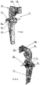
Fig. 1 is a vertical section of the replica,Fig. 2 - vertical section of the replica within the trigger unit with the released trigger,Fig. 3 and Fig. 4 - axonometric views of the trigger,Fig. 5 shows the position of the pressed trigger in with reference to photoelements of the trigger sensor located on the PCB, andFig. 6 - a half-sectional view of the trigger embedded in both halves of the replica frame. - The exemplary trigger system for the replica comprises the following elements built inside the connected
frame halves - a single element trigger 1, bearing in the axis of rotation O in both
frame halves spring 16, where thetrigger 1 at its upper end above the axis of rotation O has a surface obscuring the light streams in theoptoelectric sensor - printed
circuit board 2, fixed internally to one of theframe halves 3a perpendicular to the axis of rotation O oftrigger 1, which comprises anoptoelectronic sensor trigger 1 position, composed of alight transmitter 21 and alight receiver 22 located on theelectronic circuit board 2 in center angle ω not greater than 50° in relation to the axis of rotation O oftrigger 1. - Upper part of the
trigger 1 has a form of anangle bracket 13, with along arm 13x and ashort arm 13y, wherein thelong arm 13x is perpendicular to the axis rotation O of thetrigger 1 and the inner surface of thelong arm 13x is a reflectingsurface 14, reflecting light emitted by thelight emitter 21. Theshort arm 13y faces towards theelectronic circuit board 2, the length of theshort arm 13y is being smaller than the distance B between thisboard 2 and theframe half 3a opposite thereto. The reflectingsurface 14 has such dimensions where in the release position of thetrigger 11, it covers only the projection of thetransmitter 21, while when thetrigger 11 is moved to the fully depressed b position, it simultaneously covers the projections of thetransmitter 21 and thereflected light receiver 22. The resultingoptoelectric sensor signal plate 2 activates the ball missile firing unit. - At the level of the axis of rotation O, the
trigger 1 has asupport 15 protruding in the opposite direction to the position of theangle bracket 13. Thesupport 15 in the released position and thetrigger blade 11 rests with its lower surface against both halves of theframe frame 3b under the pressure of atorsion spring 16 embedded with a coil on thepin 12 brought out on both sides in the axis of rotation O of thetrigger 1. The bent end of one arm of thetorsion spring 16 is inserted into thelongitudinal hole 17 in thebracket 15 of thetrigger 1, while the other, opposing arm of thetorsion spring 16 rests against the inside of the replica's frame on the side under theangle bracket 13. -
- 1.
- Trigger
11. trigger blade
12. pin
13. angle bracket
13x. long arm
13y. short arm
14. reflecting surface
15. support
16. torsion spring
17. longitudinal hole
O. axis of rotation - 2.
- Electronic circuit board
21. optoelectronic sensor transmitter
22. optoelectronic sensor receiver - 3a, 3b
- right and left half of frame
- a.
- trigger blades release possition
- b.
- trigger blades press possition
- w.
- angle between optoelectronic sensor transmiter and receiver
- B.
- distance between the board and the opposite half of the frame
Claims (6)
- A trigger for a gun replica, bearing in the axis of rotation (O) in both frame halves (3a, 3b) and attached with a spring (16) toward the release position (a) of the triggers blade (11) with a perpendicular position to the shot line, wherein the trigger (1) at its upper end above the axis of rotation (O) has a surface obscuring the light streams in the optoelectric sensor (21, 22), characterized in that the obscuring surface on the inner surface of the long arm (13x) of the angle bracket (13) is a reflecting surface (14), wherein the bracket (13) is situated with a long arm (13x) perpendicular to the axis of rotation (O) of the trigger (1) and with the short arm (13y) facing toward the printed circuit board (2), wherein the short arms (13y) length is less than the distance (B) between the board (2) and the opposite half of the frame (3a), wherein the reflecting surface (14) in the release position (a) of the trigger blade (11) only covers the projection of the transmitter (21), and when the trigger blade (11) is moved to the fully depressed position (b), it simultaneously covers the projection of the transmitter (21) and receiver (22) of the reflected light and the resulting signal of the opto-electrical sensor (21, 22) is processed in the board's electronic layout (2) and activates the ball projectile shot assembly.
- Trigger according to claim 1, characterized in that it has a support (15) at the level of the axis of rotation (O), wherein the support (15) is projecting in the opposite direction to the position of the angle bracket (13) and in the release position (a) of the trigger blade (11) the support (15) is resting its lower surface on the halves of the frame (3a, 3b) or on only one half of the frame (3b), being pressed by a torsion spring (16) mounted with a coil placed on a pin (12), wherein the pin (12) is led out on both sides in the axis of rotation (O) of the trigger (1), wherein the bent end of one arm of the spring (16) is inserted into the longitudinal hole (17) in the support (15), wherein the second, opposing arm of the spring (16) rests on the frame on the side under the angle bracket (13).
- Trigger, according to claim 1, wherein the long arm (13x) of the bracket (13) has a two-step recess along the bottom edge.
- Trigger, according to claim 1, wherein the long arm (13x) of the bracket (13) has a cut upper corner on the side opposite to the short arm (13y).
- Trigger, according to claim 1, characterized in that the trigger (1) is made of metal and has a polished reflective surface (14).
- Trigger, according to claim 1, wherein the reflecting surface (14) of the trigger (1) is covered with a light reflecting layer, made especially of silver, aluminum, foil or reflective paint.
Applications Claiming Priority (1)
| Application Number | Priority Date | Filing Date | Title |
|---|---|---|---|
| PL43243020 | 2020-10-23 |
Publications (3)
| Publication Number | Publication Date |
|---|---|
| EP4043824A1 true EP4043824A1 (en) | 2022-08-17 |
| EP4043824B1 EP4043824B1 (en) | 2026-03-04 |
| EP4043824C0 EP4043824C0 (en) | 2026-03-04 |
Family
ID=81326040
Family Applications (1)
| Application Number | Title | Priority Date | Filing Date |
|---|---|---|---|
| EP21204356.6A Active EP4043824B1 (en) | 2020-10-23 | 2021-10-23 | Replica weapon having a trigger |
Country Status (1)
| Country | Link |
|---|---|
| EP (1) | EP4043824B1 (en) |
Citations (4)
| Publication number | Priority date | Publication date | Assignee | Title |
|---|---|---|---|---|
| US20070189014A1 (en) * | 2006-02-16 | 2007-08-16 | Hsin-Cheng Yeh | Light reflecting triggering device for a paintball gun |
| EP3367041A1 (en) | 2017-02-28 | 2018-08-29 | Magna Composites, S.L. | Optical trigger system for a weapon |
| EP3553455A1 (en) * | 2018-04-13 | 2019-10-16 | Gate, Menet, Wojtak sp. j. | The system and method of detecting the position of the trigger in gun replicas |
| JP3227466U (en) * | 2019-05-31 | 2020-08-27 | ゲート エンタープライズ エスペー.ゼット オー.オー.エスペー.カ.GATE Enterprise Sp.z o.o.Sp.k. | Air gun trigger detection system that uses light reflection |
-
2021
- 2021-10-23 EP EP21204356.6A patent/EP4043824B1/en active Active
Patent Citations (5)
| Publication number | Priority date | Publication date | Assignee | Title |
|---|---|---|---|---|
| US20070189014A1 (en) * | 2006-02-16 | 2007-08-16 | Hsin-Cheng Yeh | Light reflecting triggering device for a paintball gun |
| EP3367041A1 (en) | 2017-02-28 | 2018-08-29 | Magna Composites, S.L. | Optical trigger system for a weapon |
| EP3553455A1 (en) * | 2018-04-13 | 2019-10-16 | Gate, Menet, Wojtak sp. j. | The system and method of detecting the position of the trigger in gun replicas |
| PL234505B1 (en) | 2018-04-13 | 2020-03-31 | Gate Menet Wojtak Spolka Jawna | System and method for detection of the trigger position in the replica weapons |
| JP3227466U (en) * | 2019-05-31 | 2020-08-27 | ゲート エンタープライズ エスペー.ゼット オー.オー.エスペー.カ.GATE Enterprise Sp.z o.o.Sp.k. | Air gun trigger detection system that uses light reflection |
Also Published As
| Publication number | Publication date |
|---|---|
| EP4043824B1 (en) | 2026-03-04 |
| EP4043824C0 (en) | 2026-03-04 |
Similar Documents
| Publication | Publication Date | Title |
|---|---|---|
| US5485695A (en) | Laser aiming device | |
| US4362145A (en) | Practice weapon including pellet gun mounted within missile firing tube | |
| US8448373B2 (en) | Gun sight | |
| US20170307333A1 (en) | System and method for marksmanship training | |
| US20160054082A1 (en) | Trigger Assembly and Method of Optical Detection of a Trigger Assembly State | |
| WO2010045543A2 (en) | Trigger activated switch | |
| EP1257777A2 (en) | Laser transmitter assembly configured for placement within a firing chamber and method of simulating firearm operation | |
| ES2657066B1 (en) | SYSTEM TO SHOOT A GUN | |
| US4194304A (en) | Loader and recoil simulation trainer for artillery crews | |
| US12485344B2 (en) | Triggering mechanism | |
| US11525646B1 (en) | Optical trigger for bows, crossbows and firearms | |
| EP4043824B1 (en) | Replica weapon having a trigger | |
| US20060011182A1 (en) | Electrically activated arrow rest | |
| EP3553455B1 (en) | System and method of detecting the position of the trigger in gun replicas | |
| JP3227466U (en) | Air gun trigger detection system that uses light reflection | |
| SE8405150D0 (en) | WEAPONS FACILITY | |
| CN216145294U (en) | Guns for virtual simulation training | |
| US3916867A (en) | Projectile projecting toy gun having slidable pivotable barrel member | |
| KR200376721Y1 (en) | Laser light Generating Device for an Electronic Shooting Training System | |
| RU2680172C2 (en) | Nozzle for simulating combat fire | |
| CN114530071A (en) | Gun and training system | |
| CN214470373U (en) | Special control switch for simulated shooting device | |
| CN209961077U (en) | Laser sight adjusting mechanism, laser sight and shooting device | |
| CN222188017U (en) | A rotary trigger electric switch type firing safety mechanism for laser gun | |
| RU2120595C1 (en) | Mechanism cocking spring pneumatic weapon |
Legal Events
| Date | Code | Title | Description |
|---|---|---|---|
| PUAI | Public reference made under article 153(3) epc to a published international application that has entered the european phase |
Free format text: ORIGINAL CODE: 0009012 |
|
| STAA | Information on the status of an ep patent application or granted ep patent |
Free format text: STATUS: THE APPLICATION HAS BEEN PUBLISHED |
|
| AK | Designated contracting states |
Kind code of ref document: A1 Designated state(s): AL AT BE BG CH CY CZ DE DK EE ES FI FR GB GR HR HU IE IS IT LI LT LU LV MC MK MT NL NO PL PT RO RS SE SI SK SM TR |
|
| STAA | Information on the status of an ep patent application or granted ep patent |
Free format text: STATUS: REQUEST FOR EXAMINATION WAS MADE |
|
| 17P | Request for examination filed |
Effective date: 20230217 |
|
| RBV | Designated contracting states (corrected) |
Designated state(s): AL AT BE BG CH CY CZ DE DK EE ES FI FR GB GR HR HU IE IS IT LI LT LU LV MC MK MT NL NO PL PT RO RS SE SI SK SM TR |
|
| GRAP | Despatch of communication of intention to grant a patent |
Free format text: ORIGINAL CODE: EPIDOSNIGR1 |
|
| STAA | Information on the status of an ep patent application or granted ep patent |
Free format text: STATUS: GRANT OF PATENT IS INTENDED |
|
| INTG | Intention to grant announced |
Effective date: 20250905 |
|
| GRAS | Grant fee paid |
Free format text: ORIGINAL CODE: EPIDOSNIGR3 |
|
| GRAA | (expected) grant |
Free format text: ORIGINAL CODE: 0009210 |
|
| STAA | Information on the status of an ep patent application or granted ep patent |
Free format text: STATUS: THE PATENT HAS BEEN GRANTED |
|
| RAP3 | Party data changed (applicant data changed or rights of an application transferred) |
Owner name: GATE ENTERPRISE SP. Z O.O. |
|
| AK | Designated contracting states |
Kind code of ref document: B1 Designated state(s): AL AT BE BG CH CY CZ DE DK EE ES FI FR GB GR HR HU IE IS IT LI LT LU LV MC MK MT NL NO PL PT RO RS SE SI SK SM TR |
|
| RAP3 | Party data changed (applicant data changed or rights of an application transferred) |
Owner name: GATE ENTERPRISE SP. Z O.O. |
|
| REG | Reference to a national code |
Ref country code: CH Ref legal event code: F10 Free format text: ST27 STATUS EVENT CODE: U-0-0-F10-F00 (AS PROVIDED BY THE NATIONAL OFFICE) Effective date: 20260304 Ref country code: GB Ref legal event code: FG4D |
|
| REG | Reference to a national code |
Ref country code: DE Ref legal event code: R096 Ref document number: 602021049115 Country of ref document: DE |
|
| REG | Reference to a national code |
Ref country code: IE Ref legal event code: FG4D |
|
| U01 | Request for unitary effect filed |
Effective date: 20260407 |
|
| U07 | Unitary effect registered |
Designated state(s): AT BE BG DE DK EE FI FR IT LT LU LV MT NL PT RO SE SI Effective date: 20260413 |
|
| PG25 | Lapsed in a contracting state [announced via postgrant information from national office to epo] |
Ref country code: RS Free format text: LAPSE BECAUSE OF FAILURE TO SUBMIT A TRANSLATION OF THE DESCRIPTION OR TO PAY THE FEE WITHIN THE PRESCRIBED TIME-LIMIT Effective date: 20260604 |
|
| PG25 | Lapsed in a contracting state [announced via postgrant information from national office to epo] |
Ref country code: ES Free format text: LAPSE BECAUSE OF FAILURE TO SUBMIT A TRANSLATION OF THE DESCRIPTION OR TO PAY THE FEE WITHIN THE PRESCRIBED TIME-LIMIT Effective date: 20260304 |
|
| PG25 | Lapsed in a contracting state [announced via postgrant information from national office to epo] |
Ref country code: GR Free format text: LAPSE BECAUSE OF FAILURE TO SUBMIT A TRANSLATION OF THE DESCRIPTION OR TO PAY THE FEE WITHIN THE PRESCRIBED TIME-LIMIT Effective date: 20260605 |
|
| PG25 | Lapsed in a contracting state [announced via postgrant information from national office to epo] |
Ref country code: NO Free format text: LAPSE BECAUSE OF FAILURE TO SUBMIT A TRANSLATION OF THE DESCRIPTION OR TO PAY THE FEE WITHIN THE PRESCRIBED TIME-LIMIT Effective date: 20260604 |
|
| PG25 | Lapsed in a contracting state [announced via postgrant information from national office to epo] |
Ref country code: HR Free format text: LAPSE BECAUSE OF FAILURE TO SUBMIT A TRANSLATION OF THE DESCRIPTION OR TO PAY THE FEE WITHIN THE PRESCRIBED TIME-LIMIT Effective date: 20260304 |