EP4043822A1 - Loop heat pipe - Google Patents
Loop heat pipe Download PDFInfo
- Publication number
- EP4043822A1 EP4043822A1 EP22155420.7A EP22155420A EP4043822A1 EP 4043822 A1 EP4043822 A1 EP 4043822A1 EP 22155420 A EP22155420 A EP 22155420A EP 4043822 A1 EP4043822 A1 EP 4043822A1
- Authority
- EP
- European Patent Office
- Prior art keywords
- metal layer
- column portion
- bottomed hole
- face
- porous body
- Prior art date
- Legal status (The legal status is an assumption and is not a legal conclusion. Google has not performed a legal analysis and makes no representation as to the accuracy of the status listed.)
- Granted
Links
Images





Classifications
-
- F—MECHANICAL ENGINEERING; LIGHTING; HEATING; WEAPONS; BLASTING
- F28—HEAT EXCHANGE IN GENERAL
- F28D—HEAT-EXCHANGE APPARATUS, NOT PROVIDED FOR IN ANOTHER SUBCLASS, IN WHICH THE HEAT-EXCHANGE MEDIA DO NOT COME INTO DIRECT CONTACT
- F28D15/00—Heat-exchange apparatus with the intermediate heat-transfer medium in closed tubes passing into or through the conduit walls ; Heat-exchange apparatus employing intermediate heat-transfer medium or bodies
- F28D15/02—Heat-exchange apparatus with the intermediate heat-transfer medium in closed tubes passing into or through the conduit walls ; Heat-exchange apparatus employing intermediate heat-transfer medium or bodies in which the medium condenses and evaporates, e.g. heat pipes
- F28D15/04—Heat-exchange apparatus with the intermediate heat-transfer medium in closed tubes passing into or through the conduit walls ; Heat-exchange apparatus employing intermediate heat-transfer medium or bodies in which the medium condenses and evaporates, e.g. heat pipes with tubes having a capillary structure
- F28D15/046—Heat-exchange apparatus with the intermediate heat-transfer medium in closed tubes passing into or through the conduit walls ; Heat-exchange apparatus employing intermediate heat-transfer medium or bodies in which the medium condenses and evaporates, e.g. heat pipes with tubes having a capillary structure characterised by the material or the construction of the capillary structure
-
- F—MECHANICAL ENGINEERING; LIGHTING; HEATING; WEAPONS; BLASTING
- F28—HEAT EXCHANGE IN GENERAL
- F28D—HEAT-EXCHANGE APPARATUS, NOT PROVIDED FOR IN ANOTHER SUBCLASS, IN WHICH THE HEAT-EXCHANGE MEDIA DO NOT COME INTO DIRECT CONTACT
- F28D15/00—Heat-exchange apparatus with the intermediate heat-transfer medium in closed tubes passing into or through the conduit walls ; Heat-exchange apparatus employing intermediate heat-transfer medium or bodies
- F28D15/02—Heat-exchange apparatus with the intermediate heat-transfer medium in closed tubes passing into or through the conduit walls ; Heat-exchange apparatus employing intermediate heat-transfer medium or bodies in which the medium condenses and evaporates, e.g. heat pipes
- F28D15/0266—Heat-exchange apparatus with the intermediate heat-transfer medium in closed tubes passing into or through the conduit walls ; Heat-exchange apparatus employing intermediate heat-transfer medium or bodies in which the medium condenses and evaporates, e.g. heat pipes with separate evaporating and condensing chambers connected by at least one conduit; Loop-type heat pipes; with multiple or common evaporating or condensing chambers
-
- F—MECHANICAL ENGINEERING; LIGHTING; HEATING; WEAPONS; BLASTING
- F28—HEAT EXCHANGE IN GENERAL
- F28D—HEAT-EXCHANGE APPARATUS, NOT PROVIDED FOR IN ANOTHER SUBCLASS, IN WHICH THE HEAT-EXCHANGE MEDIA DO NOT COME INTO DIRECT CONTACT
- F28D15/00—Heat-exchange apparatus with the intermediate heat-transfer medium in closed tubes passing into or through the conduit walls ; Heat-exchange apparatus employing intermediate heat-transfer medium or bodies
- F28D15/02—Heat-exchange apparatus with the intermediate heat-transfer medium in closed tubes passing into or through the conduit walls ; Heat-exchange apparatus employing intermediate heat-transfer medium or bodies in which the medium condenses and evaporates, e.g. heat pipes
- F28D15/04—Heat-exchange apparatus with the intermediate heat-transfer medium in closed tubes passing into or through the conduit walls ; Heat-exchange apparatus employing intermediate heat-transfer medium or bodies in which the medium condenses and evaporates, e.g. heat pipes with tubes having a capillary structure
-
- F—MECHANICAL ENGINEERING; LIGHTING; HEATING; WEAPONS; BLASTING
- F28—HEAT EXCHANGE IN GENERAL
- F28D—HEAT-EXCHANGE APPARATUS, NOT PROVIDED FOR IN ANOTHER SUBCLASS, IN WHICH THE HEAT-EXCHANGE MEDIA DO NOT COME INTO DIRECT CONTACT
- F28D15/00—Heat-exchange apparatus with the intermediate heat-transfer medium in closed tubes passing into or through the conduit walls ; Heat-exchange apparatus employing intermediate heat-transfer medium or bodies
- F28D15/02—Heat-exchange apparatus with the intermediate heat-transfer medium in closed tubes passing into or through the conduit walls ; Heat-exchange apparatus employing intermediate heat-transfer medium or bodies in which the medium condenses and evaporates, e.g. heat pipes
- F28D15/04—Heat-exchange apparatus with the intermediate heat-transfer medium in closed tubes passing into or through the conduit walls ; Heat-exchange apparatus employing intermediate heat-transfer medium or bodies in which the medium condenses and evaporates, e.g. heat pipes with tubes having a capillary structure
- F28D15/043—Heat-exchange apparatus with the intermediate heat-transfer medium in closed tubes passing into or through the conduit walls ; Heat-exchange apparatus employing intermediate heat-transfer medium or bodies in which the medium condenses and evaporates, e.g. heat pipes with tubes having a capillary structure forming loops, e.g. capillary pumped loops
-
- F—MECHANICAL ENGINEERING; LIGHTING; HEATING; WEAPONS; BLASTING
- F28—HEAT EXCHANGE IN GENERAL
- F28F—DETAILS OF HEAT-EXCHANGE AND HEAT-TRANSFER APPARATUS, OF GENERAL APPLICATION
- F28F3/00—Plate-like or laminated elements; Assemblies of plate-like or laminated elements
- F28F3/08—Elements constructed for building-up into stacks, e.g. capable of being taken apart for cleaning
- F28F3/086—Elements constructed for building-up into stacks, e.g. capable of being taken apart for cleaning having one or more openings therein forming tubular heat-exchange passages
-
- H—ELECTRICITY
- H05—ELECTRIC TECHNIQUES NOT OTHERWISE PROVIDED FOR
- H05K—PRINTED CIRCUITS; CASINGS OR CONSTRUCTIONAL DETAILS OF ELECTRIC APPARATUS; MANUFACTURE OF ASSEMBLAGES OF ELECTRICAL COMPONENTS
- H05K7/00—Constructional details common to different types of electric apparatus
- H05K7/20—Modifications to facilitate cooling, ventilating, or heating
- H05K7/2029—Modifications to facilitate cooling, ventilating, or heating using a liquid coolant with phase change in electronic enclosures
- H05K7/20336—Heat pipes, e.g. wicks or capillary pumps
-
- F—MECHANICAL ENGINEERING; LIGHTING; HEATING; WEAPONS; BLASTING
- F28—HEAT EXCHANGE IN GENERAL
- F28F—DETAILS OF HEAT-EXCHANGE AND HEAT-TRANSFER APPARATUS, OF GENERAL APPLICATION
- F28F2275/00—Fastening; Joining
- F28F2275/02—Fastening; Joining by using bonding materials; by embedding elements in particular materials
Definitions
- the present disclosure relates to a loop heat pipe.
- a heat pipe that transports heat using a phase change of a working fluid has been proposed as a device for cooling a heating component of a semiconductor device (such as a CPU) mounted on an electronic apparatus (e.g. see JP Patent No. 6291000 and JP Patent No. 6400240 ).
- a loop heat pipe including an evaporator that vaporizes a working fluid by heat of a heating component, and a condenser that cools and condenses the vaporized working fluid.
- the evaporator and the condenser are connected to each other through a liquid pipe and a vapor pipe, that form a loop-like flow channel.
- the working fluid flows through the loop-like flow channel in one direction.
- the flow channel is formed by metal layers stacked on one another.
- the metal layers have a pair of outer metal layers that are provided at opposite ends in a direction in which the metal layers are stacked, and a plurality of inner metal layers that are provided between the pair of outer metal layers.
- a porous body including pores is provided in the inner metal layers. The pores are formed by such partial communication that bottomed holes recessed from one side of each of the inner metal layers partially communicate with bottomed holes recessed from the other side of the inner metal layer.
- One end side of the inner metal layers in their stacking direction is bonded to one of the outer metal layers, and the other end side of the inner metal layers in their stacking direction is bonded to the other outer metal layer.
- volume expansion may occur in the loop heat pipe in accordance with characteristics of the working fluid sealed inside the flow channel. Further, when an ambient temperature of the loop heat pipe is lower than a freezing point of the working fluid, the working fluid freezes and solidifies in the loop heat pipe. On this occasion, volume expansion may occur as the working fluid undergoes a liquid-to-solid phase change. When such volume expansion occurs, the outer metal layers may be deformed to expand outwardly so that the outer metal layers are separated from the inner metal layers.
- Certain embodiment provides a loop heat pipe.
- the loop heat pipe comprises:
- At least one of the evaporator, the condenser, the liquid pipe, and the vapor pipe comprises a first outer metal layer, a second outer metal layer, and an inner metal layer that is provided between the first outer metal layer and the second outer metal layer.
- the inner metal layer comprises a porous body.
- the porous body comprises:
- a loop heat pipe 10 shown in FIG. 1 is, for example, accommodated in a mobile electronic device M1 such as a smartphone or a tablet terminal.
- the loop heat pipe 10 has an evaporator 11, a vapor pipe 12, a condenser 13, and a liquid pipe 14.
- the evaporator 11 and the condenser 13 are connected to each other by the vapor pipe 12 and the liquid pipe 14.
- the evaporator 11 has a function of vaporizing a working fluid C to generate vapor Cv.
- the vapor Cv generated in the evaporator 11 is sent to the condenser 13 through the vapor pipe 12.
- the condenser 13 has a function of condensing the vapor Cv of the working fluid C.
- the condensed working fluid C is sent to the evaporator 11 through the liquid pipe 14.
- the vapor pipe 12 and the liquid pipe 14 form a loop-like flow channel 15 through which the working fluid C or the vapor Cv is made to flow.
- the vapor pipe 12 is, for example, formed into a long tubular body.
- the liquid pipe 14 is, for example, formed into a long tubular body.
- the vapor pipe 12 and the liquid pipe 14 are, for example, the same in dimension in a length direction (i.e. length) as each other.
- the length of the vapor pipe 12 and the length of the liquid pipe 14 may be different from each other.
- the length of the vapor pipe 12 may be shorter than the length of the liquid pipe 14.
- the "length direction" of the evaporator 11, the vapor pipe 12, the condenser 13, and the liquid pipe 14 in the present specification is a direction consistent with a direction (see arrows in FIG. 1 ) in which the working fluid C or the vapor Cv in each member flows.
- the evaporator 11 is fixed in close contact with a heating component (not shown).
- the working fluid C in the evaporator 11 is vaporized by heat generated by the heating component, so that the vapor Cv is generated.
- a thermal interface material may be interposed between the evaporator 11 and the heating component. The TIM reduces thermal contact resistance between the heating component and the evaporator 11 to make the heat be conducted from the heating component to the evaporator 11 smoothly.
- the vapor pipe 12 has, for example, a pair of pipe walls 12w that are provided on opposite sides in a width direction of the vapor pipe 12 orthogonal to the length direction of the vapor pipe 12 in plan view, and a flow channel 12r that is provided between the pair of pipe walls 12w.
- the flow channel 12r communicates with an internal space of the evaporator 11.
- the flow channel 12r is a part of the loop-like flow channel 15.
- the vapor Cv generated in the evaporator 11 is guided to the condenser 13 through the vapor pipe 12.
- the condenser 13 has, for example, a heat dissipating plate 13p whose area has been increased for heat dissipation, and a flow channel 13r that meanders inside the heat dissipating plate 13p.
- the flow channel 13r is a part of the loop-like flow channel 15. The vapor Cv guided through the vapor pipe 12 is condensed in the condenser 13.
- the liquid pipe 14 has, for example, a pair of pipe walls 14w that are provided on opposite sides in a width direction of the liquid pipe 14 orthogonal to the length direction of the liquid pipe 14 in plan view, and a flow channel 14r that is provided between the pair of pipe walls 14w.
- the flow channel 14r communicates with the flow channel 13r of the condenser 13, and communicates with the internal space of the evaporator 11.
- the flow channel 14r is a part of the loop-like flow channel 15.
- the liquid pipe 14 has a porous body 20.
- the porous body 20 is, for example, formed to extend from the condenser 13 to the evaporator 11 along the length direction of the liquid pipe 14.
- the porous body 20 guides the working fluid C condensed in the condenser 13 to the evaporator 11 by capillary force generated in the porous body 20. That is, the working fluid C condensed in the condenser 13 is guided to the evaporator 11 through the liquid pipe 14.
- a porous body similar to or the same as the porous body 20 is also provided in the evaporator 11.
- the heat generated by the heating component is transferred to the condenser 13 and dissipated in the condenser 13.
- the heating component is cooled so that an increase in temperature of the heating component can be suppressed.
- a fluid high in vapor pressure and large in latent heat of vaporization is used as the working fluid C.
- the heating component can be efficiently cooled by the latent heat of vaporization.
- ammonia, water, chlorofluorocarbon, alcohol, acetone, or the like can be used as the working fluid C.
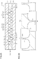
- FIG. 2A shows a section of the liquid pipe 14 taken along a line 2-2 in FIG. 1 .
- This section is a face orthogonal to the flow direction (the direction indicated by the arrows in FIG. 1 ) of the working fluid C in the liquid pipe 14.
- FIG. 2B is an enlarged sectional view in which a portion of the liquid pipe 14 shown in FIG. 2A is enlarged.
- the liquid pipe 14 has a structure in which, for example, three metal layers 31, 32, and 33 are stacked on one another.
- the liquid pipe 14 has a structure in which the metal layer 32, which is an inner metal layer, is disposed between the metal layers 31 and 33, which are a pair of outer metal layers.
- the inner metal layer of the liquid pipe 14 in the present embodiment is made up of only one metal layer 32.
- Each of the metal layers 31 to 33 is, for example, a copper (Cu) layer having excellent heat conductivity.
- the metal layers 31 to 33 are, for example, directly bonded to one another by solid-phase bonding such as diffusion bonding, pressure welding, friction welding or ultrasonic bonding.
- solid-phase bonding such as diffusion bonding, pressure welding, friction welding or ultrasonic bonding.
- the metal layers 31 to 33 are distinguished from one another by a solid line.
- an interface between adjacent ones of the metal layers 31 to 33 may disappear so that a boundary therebetween may be unclear.
- each of the metal layers 31 to 33 is not limited to the copper layer, but may be formed of a stainless steel layer, an aluminum layer, a magnesium alloy layer, or the like. Further, a material used for forming some of the stacked metal layers 31 to 33 may be different from a material used for forming the others of the metal layers 31 to 33. Thickness of each of the metal layers 31 to 33 can be, for example, set in a range of about 50 ⁇ m to 200 ⁇ m. Incidentally, some of the metal layers 31 to 33 may be made different in thickness from the others of the metal layers 31 to 33, or all the metal layers 31 to 33 may be made different in thickness from one another.
- the liquid pipe 14 that are made up of the stacked metal layers 31 to 33 has the pair of pipe walls 14w that are provided at the opposite ends in the width direction (left-right direction in FIG. 2A ) of the liquid pipe 14 orthogonal to the stacking direction of the metal layers 31 to 33, and the porous body 20 that is provided between the pair of pipe walls 14w.
- the porous body 20 is, for example, formed in continuity with the pipe walls 14w.
- the metal layer 31 is stacked on an upper face of the metal layer 32.
- One or more grooves 31g are formed in a lower face of the metal layer 31.
- Each of the grooves 31g is formed so as to be recessed from the lower face of the metal layer 31 to a thicknesswise central portion of the metal layer 31.
- the metal layer 32 is provided between the metal layer 31 and the metal layer 33.
- the upper face of the metal layer 32 is bonded to the lower face of the metal layer 31.
- a lower face of the metal layer 32 is bonded to an upper face of the metal layer 33.
- the metal layer 32 has a pair of wall portions 32w that are provided at the widthwise opposite ends of the liquid pipe 14, and a porous body 32s that is provided between the pair of wall portions 32w.
- the metal layer 33 is provided on the lower face of the metal layer 32.
- One or more grooves 33g are formed in the upper face of the metal layer 33.
- Each of the grooves 33g is formed so as to be recessed from the upper face of the metal layer 33 to a thicknesswise central portion of the metal layer 33.
- the pipe walls 14w are, for example, respectively constituted by the wall portions 32w of the metal layer 32, which is the inner metal layer.
- Each of the pipe walls 14w in the present embodiment is constituted by only the wall portion 32w. No holes or grooves are formed in each of the wall portions 32w.
- the porous body 20 has, for example, the porous body 32s belonging to the metal layer 32, which is the inner metal layer, and the grooves 31g and 33g respectively belonging to the metal layers 31 and 33, which are the outer metal layers.
- the porous body 32s has bottomed holes 40, bottomed holes 50, and pores 60.
- Each of the bottom holes 40 is recessed from the upper face of the metal layer 32 to a thicknesswise central portion of the metal layer 32.
- Each of the bottomed holes 50 is recessed from the lower face of the metal layer 32 to a thicknesswise central portion of the metal layer 32.
- the pores 60 are formed by partial communication between the bottomed holes 40 and the bottomed holes 50. Depth of each of the bottomed holes 40 and 50 can be, for example, set in a range of about 25 ⁇ m to 100 ⁇ m.
- an inner face of the bottomed hole 40, 50 is, for example, formed into a shape that is continuous like an arc from an opening side (upper/lower face side of the metal layer 32) to a bottom face side.
- An inner side face of the bottomed hole 40, 50 is formed into an arc-shaped curved face in sectional view.
- the sectional shape of the inner side face of the bottomed hole 40, 50 is, for example, formed into the arc-shaped curved face so that an opening width in the middle of the depth direction of the bottomed hole 40, 50 is widest.
- a bottom face of the bottomed hole 40, 50 is, for example, formed into an arc-shaped curved face.
- the bottom face of the bottomed hole 40, 50 is, for example, formed in continuity with the inner side face of the bottomed hole 40, 50.
- the radius of curvature of the bottom face of the bottomed hole 40, 50 may be equal to the radius of curvature of the inner side face of the bottomed hole 40, 50, or may be different from the radius of curvature of the inner side face of the bottomed hole 40, 50.
- the expression "equal" in this specification includes not only a case where the objects to be compared are exactly equal, but also a case where there is some difference between the objects to be compared due to an influence of dimensional tolerance or the like.
- the inner face of the bottomed hole 40, 50 may be formed into a concave shape that is a semicircle or a semiellipse in section.
- the expression “semicircle” in this specification includes not only a semicircle that is a halved part of a perfect circle, but also, for example, an arc that is longer or shorter than the semicircle.
- the expression “semiellipse” in this specification includes not only a semiellipse that is a halved part of an ellipse, but also, for example, an arc that is longer or shorter than the semiellipse.
- the inner face of the bottomed hole 40, 50 may be formed into a tapered shape that is wider as it goes from the bottom face side toward the opening side.
- the bottom face of the bottomed hole 40, 50 may be formed into a flat face parallel to the upper face of the metal layer 32, and the inner side face of the bottomed hole 40, 50 may be formed to extend perpendicularly to the bottom face.
- each of the bottomed holes 40 and 50 is, for example, formed into a circular shape in plan view.
- the diameter of the bottomed hole 40, 50 can be, for example, set in a range of about 100 ⁇ m to 400 ⁇ m.
- the bottomed hole 40, 50 can be formed into any shape such as an ellipse or a polygon in plan view.
- the bottomed hole 40 and the bottomed hole 50 partially overlap with each other in plan view.
- the pore 60 through which the bottomed hole 40 and the bottomed hole 50 partially communicate with each other is formed at the portion where the bottomed hole 40 and the bottomed hole 50 overlap with each other in plan view.
- Each of the bottomed holes 40 has a column portion 41 inside. That is, the metal layer 32 has the column portions 41 provided inside the bottomed holes 40 respectively.
- Each of the column portions 41 is provided apart from an entire circumference of the inner side face of the bottomed hole 40. That is, a space is formed over the entire circumference of the bottomed hole 40 between an outer circumferential face of the column portion 41 and the inner side face of the bottomed hole 40.
- the column portion 41 is provided in a central portion of the bottomed hole 40 in plan view. As shown in FIG. 3 , the column portion 41 in the present embodiment is provided at the center of the bottomed hole 40 in plan view.
- the column portion 41 is, for example, provided at a position that does not overlap with any part of the bottomed hole 50 in plan view.
- the column portion 41 can be formed into any shape with any size in plan view.
- the planar shape of the column portion 41 may be a shape equal to the planar shape of the bottomed hole 40, or a shape different from the planar shape of the bottomed hole 40.
- the planar shape of the column portion 41 can be, for example, set to have a size about 10% to 20% of the size of the planar shape of the bottomed hole 40.
- the column portion 41 can be shaped like a circle with a diameter of about 10 ⁇ m to 50 ⁇ m in plan view.
- the column portion 41 is formed into a concentric shape with the inner side face of the bottomed hole 40.
- the column portion 41 extends from the bottom face of the bottomed hole 40 to the upper face of the metal layer 32 in the thickness direction of the metal layer 32.
- An upper face 41A of the column portion 41 is formed on the same plane as the upper face of the metal layer 32. Thickness of the column portion 41 is set to be as long as the depth of the bottomed hole 40.
- the column portion 41 is formed integrally and in continuity with the metal layer 32 constituting the inner face of the bottomed hole 40.
- the column portion 41 has a proximal end and a distal end in the thickness direction of the column portion 41.
- the proximal end of the column portion 41 is connected to the bottom face of the bottomed hole 40.
- the distal end of the column portion 41 is provided on an opposite side to the proximal end in the thickness direction of the column portion 41.
- the distal end of the column portion 41 has the upper face 41A of the column portion 41.
- the column portion 41 is, for example, formed so that a thicknesswise central portion of the column portion 41 is thinner than each of the proximal end and the distal end of the column portion 41.
- the column portion 41 is, for example, formed so that the thicknesswise central portion of the column portion 41 is thinnest.
- the sectional shape of the outer circumferential face of the column portion 41 is formed curvilinearly so as to have "constriction" in the thicknesswise central portion of the column portion 41.
- the outer circumferential face of the column portion 41 is formed into an arc-shaped curved face in sectional view.
- the column portion 41 is formed so as to be thicker as it goes from the thicknesswise central portion of the column portion 41 toward the distal end of the column portion 41.
- the column portion 41 is formed so as to be thicker as it goes from the thicknesswise central portion of the column portion 41 toward the proximal end of the column portion 41.
- the distal end of the column portion 41 is, for example, formed to be thinner than the proximal end of the column portion 41.
- the upper face 41A of the column portion 41 is formed into a flat face parallel to the upper face of the metal layer 32.
- Each of the bottomed holes 50 has a column portion 51 inside. That is, the metal layer 32 has the column portions 51 provided inside the bottomed holes 50 respectively.
- Each of the column portions 51 is provided apart from an entire circumference of the inner side face of the bottomed hole 50. That is, a space is formed over the entire circumference of the bottomed hole 50 between an outer circumferential face of the column portion 51 and the inner side face of the bottomed hole 50.
- the column portion 51 is provided in a central portion of the bottomed hole 50 in plan view. As shown in FIG. 3 , the column portion 51 in the present embodiment is provided at the center of the bottomed hole 50 in plan view.
- the column portion 51 is, for example, provided at a position that does not overlap with any part of the bottomed hole 40 in plan view.
- the column portion 51 can be formed into any shape with any size in plan view.
- the planar shape of the column portion 51 may be a shape equal to the planar shape of the bottomed hole 50, or a shape different from the planar shape of the bottomed hole 50.
- the planar shape of the column portion 51 can be, for example, set to have a size about 10% to 20% of the size of the planar shape of the bottomed hole 50.
- the column portion 51 can be shaped like a circle with a diameter of about 10 ⁇ m to 50 ⁇ m in plan view.
- the column portion 51 is formed into a concentric shape with the inner side face of the bottomed hole 50.
- the column portion 51 extends from the bottom face of the bottomed hole 50 to the upper face of the metal layer 32 in the thickness direction of the metal layer 32.
- a lower face 51A of the column portion 51 is formed on the same plane as the lower face of the metal layer 32. Thickness of the column portion 51 is set to be as long as the depth of the bottomed hole 50.
- the column portion 51 is formed integrally and in continuity with the metal layer 32 constituting the inner face of the bottomed hole 50.
- the column portion 51 has a proximal end and a distal end in the thickness direction of the column portion 51.
- the proximal end of the column portion 51 is connected to the bottom face of the bottomed hole 50.
- the distal end of the column portion 51 has the lower face 51A of the column portion 51.
- the column portion 51 is, for example, formed so that a thicknesswise central portion of the column portion 51 is thinner than each of the proximal end and the distal end of the column portion 51.
- the column portion 51 is, for example, formed so that the thicknesswise central portion of the column portion 51 is thinnest.
- the sectional shape of the outer circumferential face of the column portion 51 is formed curvilinearly so as to have "constriction" in the thicknesswise central portion of the column portion 51.
- the outer circumferential face of the column portion 51 is formed into an arc-shaped curved face in sectional view.
- the column portion 51 is formed so as to be thicker as it goes from the thicknesswise central portion of the column portion 51 toward the distal end of the column portion 51.
- the column portion 51 is formed so as to be thicker as it goes from the thicknesswise central portion of the column portion 51 toward the proximal end of the column portion 51.
- the distal end of the column portion 51 is, for example, formed to be thinner than the proximal end of the column portion 51.
- the lower face 51A of the column portion 51 is formed into a flat face parallel to the lower face of the metal layer 32.
- the upper face 41A of the column portion 41 is bonded to the lower face of the metal layer 31.
- the entire upper face 41A of the column portion 41 is bonded to the lower face of the metal layer 31.
- the lower face 51A of the column portion 51 is bonded to the upper face of the metal layer 33.
- the entire lower face 51A of the column portion 51 is bonded to the upper face of the metal layer 33.
- An inner face of each of the grooves 31g and 33g can be formed into any shape in section.
- a bottom face of the groove 31g, 33g is, for example, formed into an arc-shaped curved face.
- An inner side face of the groove 31g, 33g is, for example, formed to extend perpendicularly to the lower face of the metal layer 31.
- the inner face of the groove 31g, 33g may be formed into a tapered shape that is wider as it goes from a bottom face side toward an opening side.
- the inner face of the groove 31g, 33g may be formed into a shape continuous like an arc from the opening side to the bottom face side.
- the inner face of the groove 31g, 33g may be formed into a concave shape that is a semicircle or a semiellipse in section.
- each of the grooves 31g is provided at a position that overlaps with portions of corresponding ones of the bottomed holes 40 in plan view.
- the groove 31g is formed so as to communicate with the corresponding bottomed holes 40.
- the groove 31g is formed so that adjacent ones of the corresponding bottomed holes 40 can communicate with each other through the groove 31g.
- the groove 31g is formed so as to extend along a direction in which the corresponding bottomed holes 40 are lined up in plan view.
- the grooves 31g are, for example, formed so as to extend in parallel with one another.
- Each of the grooves 31g is formed so as not to overlap with any parts of corresponding ones of the column portions 41 in plan view. That is, the groove 31g is provided at a position that does not overlap with the corresponding column portions 41 at all in plan view.
- the groove 31g is formed so as not to overlap with any parts of corresponding ones of the column portions 51 in plan view.
- Each of the grooves 33g is provided at a position that overlaps with portions of corresponding ones of the bottomed holes 50 in plan view.
- the groove 33g is formed so as to communicate with the corresponding bottomed holes 50.
- the groove 33g is formed so that adjacent ones of the corresponding bottomed holes 50 communicate with each other through the groove 33g.
- the groove 33g is formed so as to extend along a direction in which the corresponding bottomed holes 50 are arranged in a line in plan view.
- the grooves 33g are, for example, formed so as to extend in parallel with one another.
- the grooves 33g are, for example, formed to extend in a direction intersecting the grooves 31g in plan view.
- Each of the grooves 33g is formed so as not to overlap with any parts of corresponding ones of the column portions 51 in plan view. That is, the groove 33g is provided at a position that does not overlap with the corresponding column portions 51 at all in plan view. The groove 33g is formed so as not to overlap with any parts of corresponding ones of the column portions 41 in plan view.
- the bottomed holes 40 and 50 and the pores 60 formed in the metal layer 32 and the grooves 31g and 33g formed in the metal layers 31 and 33 respectively communicate with one another.
- a space formed by the bottomed holes 40 and 50, the pores 60, and the grooves 31g and 33g communicating with one another expands three-dimensionally.
- the bottomed holes 40 and 50, the pores 60, and the grooves 31g, 33g i.e. a flow channel belonging to the porous body 20
- an inlet for injecting the working fluid C (see FIG. 1 ) is provided in the liquid pipe 14.
- the inlet is sealed with a sealing member, and the inside of the loop heat pipe 10 is kept airtight.
- the evaporator 11, the vapor pipe 12, and the condenser 13 shown in FIG. 1 are formed by the three metal layers 31 to 33 stacked on one another in a manner similar to or the same as the liquid pipe 14 shown in FIG. 2A . That is, the loop heat pipe 10 shown in FIG. 1 has a configuration in which the three metal layers 31 to 33 are stacked on one another.
- a porous body provided in the evaporator 11 is formed into a comb teeth shape. Inside the evaporator 11, a space is formed in a region where the porous body is absent.
- a through hole that thicknesswise penetrates the metal layer 32, which is the inner metal layer, is formed so that the flow channel 12r is formed in the vapor pipe 12.
- a through hole that thicknesswise penetrates the metal layer 32, which is the inner metal layer, is formed so that the flow channel 13r is formed in the condenser 13.
- the number of the metal layers stacked on one another is not limited to three but can be set to be four or more.
- the loop heat pipe 10 has the evaporator 11 for vaporizing a working fluid C, the condenser 13 for condensing vapor Cv, the vapor pipe 12 for guiding the vaporized working fluid (i.e., the vapor Cv) to flow into the condenser 13, and the liquid pipe 14 for guiding the condensed working fluid C to flow into the evaporator 11.
- the porous body 20 is provided in the liquid pipe 14.
- the porous body 20 extends from the condenser 13 to the evaporator 11 along the length direction of the liquid pipe 14.
- the porous body 20 guides the liquid-phase working fluid C condensed in the condenser 13 to the evaporator 11 by capillary force generated in the porous body 20.
- the column portions 41 are provided inside the bottomed holes 40 formed in the metal layer 32, which is the inner metal layer, and the column portions 51 are provided inside the bottomed holes 50 formed in the metal layer 32.
- the upper faces 41A of the column portions 41 are bonded to the lower face of the metal layer 31, which is one outer metal layer, and the lower faces 51A of the column portions 51 are bonded to the upper face of the metal layer 33, which is the other outer metal layer.
- the metal layer 31 is an example of a first outer metal layer
- the metal layer 32 is an example of an inner metal layer
- the metal layer 33 is an example of a second outer metal layer.
- the bottomed hole 40 is an example of a first bottomed hole
- the column portion 41 is an example of a first column portion
- the bottomed hole 50 is an example of a second bottomed hole
- the column portion 51 is an example of a second column portion
- the groove 31g is an example of a first groove
- the groove 33g is an example of a second groove.
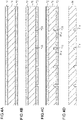
- a flat plate-like metal sheet 71 is prepared.
- the metal sheet 71 is a member that will ultimately become a metal layer 31 (see FIG. 2A ).
- the metal sheet 71 is, for example, made of copper, stainless steel, aluminum, a magnesium alloy, or the like. Thickness of the metal sheet 71 can be, for example, set in a range of about 50 ⁇ m to 200 ⁇ m.
- a resist layer 72 is formed on an upper face of the metal sheet 71, and a resist layer 73 is formed on a lower face of the metal sheet 71.
- a photosensitive dry film resist or the like, can be used as each of the resist layers 72 and 73.
- the resist layer 73 is exposed to light and developed so that opening portions 73X for selectively exposing the lower face of the metal sheet 71 are formed in the resist layer 73.
- the opening portions 73X are formed so as to correspond to grooves 31g shown in FIG. 2A .
- the metal sheet 71 exposed in the opening portions 73X is etched from the lower face side of the metal sheet 71.
- the grooves 31g are formed in the lower face of the metal sheet 71.
- the grooves 31g can be, for example, formed by wet etching on the metal sheet 71 using the resist layers 72 and 73 as etching masks.
- a ferric chloride aqueous solution or a cupric chloride aqueous solution can be used as an etching solution.
- the resist layers 72 and 73 are stripped off using a stripping solution.
- the metal layer 31 having the grooves 31g in its lower face can be formed, as shown in FIG. 4D .
- a flat plate-like metal sheet 74 is prepared.
- the metal sheet 74 is a member that will ultimately become a metal layer 33 (see FIG. 2A ).
- the metal sheet 74 is, for example, made of copper, stainless steel, aluminum, a magnesium alloy, or the like. Thickness of the metal sheet 74 can be, for example, set in a range of about 50 ⁇ m to 200 ⁇ m.
- a resist layer 75 is formed on an upper face of the metal sheet 74, and a resist layer 76 is formed on a lower face of the metal sheet 74.
- a photosensitive dry film resist or the like, can be used as each of the resist layers 75 and 76.
- the resist layer 75 is exposed to light and developed so that openings portions 75X for selectively exposing the upper face of the metal sheet 74 are formed in the resist layer 75.
- the resist layer 76 is exposed to light and developed so that opening portions 76X for selectively exposing the lower face of the metal sheet 74 are formed in the resist layer 76.
- the opening portions 75X are formed so as to correspond to bottomed holes 40 shown in FIG. 2A .
- the opening portions 76X are formed to correspond to bottomed holes 50 shown in FIG. 2A .
- the resist layer 75 has resist patterns 75A with which, of the upper face of the metal sheet 74, portions where column portions 41 shown in FIG.
- the resist patterns 75A are provided inside the opening portions 75X.
- the resist layer 76 has resist patterns 76A with which, of the lower face of the metal sheet 74, portions where column portions 51 shown in FIG. 2B will be formed are covered.
- the resist patterns 76A are provided inside the opening portions 76X.
- the metal sheet 74 exposed from the resist layer 75 is etched from the upper face side of the metal sheet 74, and the metal sheet 74 exposed from the resist layer 76 is etched from the lower face side of the metal sheet 74.
- the bottomed holes 40 having the column portions 41 are formed in the upper face of the metal sheet 74.
- the bottomed holes 50 having the column portions 51 are formed in the lower face of the metal sheet 74.
- the bottomed holes 40 and the bottomed holes 50 are formed so as to partially overlap with each other in plan view.
- the pores 60 are formed at the overlapping portions where the bottomed holes 40 and the bottomed holes 50 communicate with each other.
- the bottomed holes 40 and 50 and the column portions 41 and 51 can be, for example, formed by wet etching on the metal sheet 74 using the resist layers 75 and 76 as etching masks.
- a ferric chloride aqueous solution or a cupric chloride aqueous solution can be used as an etching solution.
- a metal layer 32 having a pair of wall portions 32w and a porous body 32s can be formed, as shown in FIG. 5D .
- the metal layer 33 is formed by a method similar to or the same as the steps shown in FIGS. 4A to 4D . Then, the metal layer 32 is disposed between the metal layer 31 and the metal layer 33.
- the stacked metal layers 31 to 33 are pressed while being heated at a predetermined temperature (e.g. about 900°C) so that the metal layers 31 to 33 are bonded to one another by solid-phase bonding.
- a predetermined temperature e.g. about 900°C
- the metal layers 31, 32, and 33 adjacent in the stacking direction are directly bonded to one another.
- the lower face of the metal layer 31 and upper faces 41A of the column portions 41 are directly bonded.
- the bottomed holes 40 and 50 and the grooves 31g and 33g are not formed in, of the metal layers 31 to 33, portions overlapping with the column portions 41 in plan view. Therefore, no space is formed in, of the metal layers 31 to 33, the portions overlapping with the column portions 41 in plan view.
- pressure can be suitably applied to the lower face of the metal layer 31 and the upper faces 41A of the column portions 41 during the pressing, so that the lower face of the metal layer 31 and the upper faces 41A of the column portions 41 can be suitably bonded.
- the upper face of the metal layer 33 and lower faces 51A of the column portions 51 are directly bonded.
- the bottomed holes 40 and 50 and the grooves 31g and 33g are not formed in, of the metal layers 31 to 33, portions overlapping with the column portions 51 in plan view. Therefore, no space is formed in, of the metal layers 31 to 33, the portions overlapping with the column portions 51 in plan view.
- pressure can be suitably applied to the upper face of the metal layer 33 and the lower faces 51A of the column portions 51 during the pressing, so that the upper face of the metal layer 33 and the lower faces 51A of the column portions 51 can be suitably bonded.
- a structure body in which the metal layers 31, 32 and 33 are stacked on one another is formed.
- a loop heat pipe 10 having an evaporator 11, a condenser 13, a vapor pipe 12 and a liquid pipe 14 shown in FIG. 1 is formed.
- a porous body 20 is formed in the liquid pipe 14.
- a working fluid C is injected into the liquid pipe 14 from a not-shown injection port, and then, the injection port is sealed.
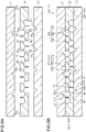
- porous bodies 20 and a flow channel 21 may be alternatively provided in the liquid pipe 14.
- the liquid pipe 14 in the present modification has a pair of pipe walls 14w, the pair of porous bodies 20 formed in continuity with the pair of pipe walls 14w, and the flow channel 21 provided between the pair of porous bodies 20.
- a flow channel 14r of the liquid pipe 14 is made up of flow channels belonging to the porous bodies 20, and the flow channel 21.
- each of the porous bodies 20 is made up of a porous body 32s of a metal layer 32 and grooves 31g and 33g of metal layers 31 and 33 in a manner similar to or the same as in the aforementioned embodiment.
- a sectional area of the flow channel 21 is, for example, formed to be larger than a sectional area of the flow channel belonging to the porous body 20.
- the flow channel 21 is made up of a through hole 32X that thicknesswise penetrates the metal layer 32, which is an inner metal layer.
- the flow channel 21 communicates with the flow channel belonging to the porous body 20.
- the through hole 32X communicates with at least one of bottomed holes 40 and 50 of the metal layer 32.
- column portions 41 and 51 are provided inside the bottomed holes 40 and 50 respectively. Upper faces 41A of the column portions 41 are bonded to a lower face of the metal layer 31, and lower faces 51A of the column portions 51 are bonded to an upper face of the metal layer 33.
- a porous body 20 and a plurality of flow channels 22 may be alternatively provided in the liquid pipe 14.
- the liquid pipe 14 in this modification has a pair of pipe walls 14w, the porous body 20 provided apart from the pipe walls 14w, and the two flow channels 22 provided between the pipe walls 14w and the porous body 20.
- a flow channel 14r of the liquid pipe 14 is made up of a flow channel belonging to the porous body 20 and the two flow channels 22.
- the porous body 20 in the present modification is provided at a widthwise central portion of the liquid pipe 14.
- the porous body 20 is provided to be isolated from the pipe walls 14w by the flow channels 22.
- the porous body 20 is made up of a porous body 32s of a metal layer 32 and grooves 31g and 33g of metal layers 31 and 33 in a manner similar to or the same as in the aforementioned embodiment.
- a sectional area of each of the flow channels 22 is, for example, formed to be larger than a sectional area of the flow channel belonging to the porous body 20.
- the flow channel 22 is made up of a through hole 32Y that thicknesswise penetrates the metal layer 32, which is an inner metal layer.
- the flow channel 22 communicates with the flow channel belonging to the porous body 20.
- the through hole 32Y communicates with at least one of bottomed holes 40 and 50 of the metal layer 32.
- column portions 41 and 51 are provided inside the bottomed holes 40 and 50 respectively. Upper faces 41A of the column portions 41 are bonded to a lower face of the metal layer 31, and lower faces 51A of the column portions 51 are bonded to an upper face of the metal layer 33.
- the porous body 20 including the bottomed holes 40 and 50 having the column portions 41 and 51 is provided in the liquid pipe 14.
- the embodiment of the present disclosure is not limited thereto.
- the porous body 20 may be provided in the evaporator 11, the vapor pipe 12 or the condenser 13.
- the porous body 20 is provided in the structure body of at least one of the evaporator 11, the vapor pipe 12, the condenser 13 and the liquid pipe 14.
- the porous body 20 may be provided only in the vapor pipe 12.
- the shapes of the bottomed holes 40 and 50 and the column portions 41 and 51 in the porous body 20 according to the aforementioned embodiment may be changed suitably.
- the depth of each of the bottomed holes 40 in the upper face of the metal layer 32 and the depth of each of the bottomed holes 50 in the lower face of the metal layer 32 may be different from each other.
- the column portions 41 and 51 are provided inside both of the bottomed holes 40 and 50.
- the embodiment of the present disclosure is not limited thereto.
- the column portions 41 may be alternatively provided only inside the bottomed holes 40 among the bottomed holes 40 and 50. That is, the column portions 51 may be removed.
- the column portions 51 may be alternatively provided only inside the bottomed holes 50 among the bottomed holes 40 and 50. That is, the column portions 41 may be removed.
- the column portion 41 is provided inside each of the bottomed holes 40.
- the embodiment of the present disclosure is not limited thereto.
- the column portion 51 is provided inside each of the bottomed holes 50.
- the embodiment of the present disclosure is not limited thereto.
- a plurality of column portions 41 may be alternatively provided inside one bottomed hole 40, and a plurality of column portions 51 may be alternatively provided inside one bottomed hole 50.
- the inner metal layer is made up of only the single metal layer 32. That is, the inner metal layer has the single-layer structure.
- the embodiment of the present disclosure is not limited thereto.
- the inner metal layer may be formed into a laminate structure in which a plurality of metal layers are stacked on one another.
- the inner metal layer in this case is made up of the plurality of metal layers stacked between the metal layer 31 and the metal layer 33.
- each of the metal layers constituting the inner metal layer has a porous body similar to or the same as the porous body 32s.
Landscapes
- Engineering & Computer Science (AREA)
- Physics & Mathematics (AREA)
- Thermal Sciences (AREA)
- Mechanical Engineering (AREA)
- General Engineering & Computer Science (AREA)
- Life Sciences & Earth Sciences (AREA)
- Sustainable Development (AREA)
- Microelectronics & Electronic Packaging (AREA)
- Cooling Or The Like Of Semiconductors Or Solid State Devices (AREA)
Abstract
Description
- The present disclosure relates to a loop heat pipe.
- In the background art, a heat pipe that transports heat using a phase change of a working fluid has been proposed as a device for cooling a heating component of a semiconductor device (such as a CPU) mounted on an electronic apparatus (e.g. see
JP Patent No. 6291000 JP Patent No. 6400240 - As an example of such a heat pipe, there has been known a loop heat pipe including an evaporator that vaporizes a working fluid by heat of a heating component, and a condenser that cools and condenses the vaporized working fluid. In the loop heat pipe, the evaporator and the condenser are connected to each other through a liquid pipe and a vapor pipe, that form a loop-like flow channel. In the loop heat pipe, the working fluid flows through the loop-like flow channel in one direction.
- The flow channel is formed by metal layers stacked on one another. The metal layers have a pair of outer metal layers that are provided at opposite ends in a direction in which the metal layers are stacked, and a plurality of inner metal layers that are provided between the pair of outer metal layers. A porous body including pores is provided in the inner metal layers. The pores are formed by such partial communication that bottomed holes recessed from one side of each of the inner metal layers partially communicate with bottomed holes recessed from the other side of the inner metal layer. One end side of the inner metal layers in their stacking direction is bonded to one of the outer metal layers, and the other end side of the inner metal layers in their stacking direction is bonded to the other outer metal layer.
- By the way, when the working fluid in a liquid phase is vaporized, volume expansion may occur in the loop heat pipe in accordance with characteristics of the working fluid sealed inside the flow channel. Further, when an ambient temperature of the loop heat pipe is lower than a freezing point of the working fluid, the working fluid freezes and solidifies in the loop heat pipe. On this occasion, volume expansion may occur as the working fluid undergoes a liquid-to-solid phase change. When such volume expansion occurs, the outer metal layers may be deformed to expand outwardly so that the outer metal layers are separated from the inner metal layers.
- Certain embodiment provides a loop heat pipe.
- The loop heat pipe comprises:
- an evaporator that vaporizes a working fluid;
- a condenser that condenses the working fluid;
- a liquid pipe that connects the evaporator and the condenser to each other;
- a vapor pipe that connects the evaporator and the condenser to each other; and
- a loop-like flow channel that is provided in each of the evaporator, the condenser, the liquid pipe, and the vapor pipe, and through which the working fluid flows.
- At least one of the evaporator, the condenser, the liquid pipe, and the vapor pipe comprises a first outer metal layer, a second outer metal layer, and an inner metal layer that is provided between the first outer metal layer and the second outer metal layer.
- The inner metal layer comprises a porous body.
- The porous body comprises:
- a first bottomed hole formed in one face of the inner metal layer;
- a second bottomed hole formed in the other face of the inner metal layer;
- a pore, wherein the first bottomed hole and the second bottomed hole partially communicates with each other through the pore; and
- a first column portion provided inside the first bottomed hole, wherein the first column portion is bonded to the first outer metal layer.
-
-
FIG. 1 is a schematic plan view showing a loop heat pipe according to an embodiment; -
FIG. 2A is a schematic sectional view (sectional view taken along a line 2-2 inFIG. 1 ) showing a liquid pipe according to the embodiment; -
FIG. 2B is an enlarged sectional view in which a portion of the liquid pipe shown inFIG. 2A is enlarged; -
FIG. 3 is a schematic plan view showing a porous body according to the embodiment; -
FIGS. 4A to 4D are schematic sectional views showing a method for manufacturing the loop heat pipe according to the embodiment; -
FIGS. 5A to 5D are schematic sectional views showing the method for manufacturing the loop heat pipe according to the embodiment; -
FIG. 6A and FIG. 6B are schematic sectional views showing the method for manufacturing the loop heat pipe according to the embodiment; -
FIG. 7 is a schematic sectional view showing a loop heat pipe according to a modification; and -
FIG. 8 is a schematic sectional view showing a loop heat pipe according to another modification. - An embodiment will be described below with reference to the accompanying drawings. Incidentally, for convenience, the accompanying drawings may show each characteristic portion in an enlarged manner in order to make the characteristic easy to understand, and a dimensional ratio among constituent elements may be different among the drawings. Further, in order to make sectional structures of members easy to understand in sectional view, some of the members to be hatched will be not hatched but drawn in a satin pattern. Incidentally, in the present specification, the expression "plan view" means a view of an object from a vertical direction (illustrated up/down direction) of
FIGS. 2A and 2B and the like, and the expression "planar shape" means a shape of the object from the vertical direction ofFIGS. 2A and 2B and the like. Further, the expressions "up/down direction" and "left/right direction" in the present specification are directions when, of each drawing, a side in which reference signs indicating the members can be accurately read is set at a normal position. - A
loop heat pipe 10 shown inFIG. 1 is, for example, accommodated in a mobile electronic device M1 such as a smartphone or a tablet terminal. Theloop heat pipe 10 has anevaporator 11, avapor pipe 12, acondenser 13, and aliquid pipe 14. - The
evaporator 11 and thecondenser 13 are connected to each other by thevapor pipe 12 and theliquid pipe 14. Theevaporator 11 has a function of vaporizing a working fluid C to generate vapor Cv. The vapor Cv generated in theevaporator 11 is sent to thecondenser 13 through thevapor pipe 12. Thecondenser 13 has a function of condensing the vapor Cv of the working fluid C. The condensed working fluid C is sent to theevaporator 11 through theliquid pipe 14. Thevapor pipe 12 and theliquid pipe 14 form a loop-like flow channel 15 through which the working fluid C or the vapor Cv is made to flow. - The
vapor pipe 12 is, for example, formed into a long tubular body. Theliquid pipe 14 is, for example, formed into a long tubular body. In the present embodiment, thevapor pipe 12 and theliquid pipe 14 are, for example, the same in dimension in a length direction (i.e. length) as each other. Incidentally, the length of thevapor pipe 12 and the length of theliquid pipe 14 may be different from each other. For example, the length of thevapor pipe 12 may be shorter than the length of theliquid pipe 14. Here, the "length direction" of theevaporator 11, thevapor pipe 12, thecondenser 13, and theliquid pipe 14 in the present specification is a direction consistent with a direction (see arrows inFIG. 1 ) in which the working fluid C or the vapor Cv in each member flows. - The
evaporator 11 is fixed in close contact with a heating component (not shown). The working fluid C in theevaporator 11 is vaporized by heat generated by the heating component, so that the vapor Cv is generated. Incidentally, a thermal interface material (TIM) may be interposed between the evaporator 11 and the heating component. The TIM reduces thermal contact resistance between the heating component and theevaporator 11 to make the heat be conducted from the heating component to theevaporator 11 smoothly. - The
vapor pipe 12 has, for example, a pair of pipe walls 12w that are provided on opposite sides in a width direction of thevapor pipe 12 orthogonal to the length direction of thevapor pipe 12 in plan view, and aflow channel 12r that is provided between the pair of pipe walls 12w. Theflow channel 12r communicates with an internal space of theevaporator 11. Theflow channel 12r is a part of the loop-like flow channel 15. The vapor Cv generated in theevaporator 11 is guided to thecondenser 13 through thevapor pipe 12. - The
condenser 13 has, for example, a heat dissipating plate 13p whose area has been increased for heat dissipation, and aflow channel 13r that meanders inside the heat dissipating plate 13p. Theflow channel 13r is a part of the loop-like flow channel 15. The vapor Cv guided through thevapor pipe 12 is condensed in thecondenser 13. - The
liquid pipe 14 has, for example, a pair ofpipe walls 14w that are provided on opposite sides in a width direction of theliquid pipe 14 orthogonal to the length direction of theliquid pipe 14 in plan view, and aflow channel 14r that is provided between the pair ofpipe walls 14w. Theflow channel 14r communicates with theflow channel 13r of thecondenser 13, and communicates with the internal space of theevaporator 11. Theflow channel 14r is a part of the loop-like flow channel 15. - The
liquid pipe 14 has aporous body 20. Theporous body 20 is, for example, formed to extend from thecondenser 13 to theevaporator 11 along the length direction of theliquid pipe 14. Theporous body 20 guides the working fluid C condensed in thecondenser 13 to theevaporator 11 by capillary force generated in theporous body 20. That is, the working fluid C condensed in thecondenser 13 is guided to theevaporator 11 through theliquid pipe 14. Incidentally, although not shown, a porous body similar to or the same as theporous body 20 is also provided in theevaporator 11. - Thus, in the
loop heat pipe 10, the heat generated by the heating component is transferred to thecondenser 13 and dissipated in thecondenser 13. As a result, the heating component is cooled so that an increase in temperature of the heating component can be suppressed. - Here, it is preferable that a fluid high in vapor pressure and large in latent heat of vaporization is used as the working fluid C. By use of such a working fluid C, the heating component can be efficiently cooled by the latent heat of vaporization. For example, ammonia, water, chlorofluorocarbon, alcohol, acetone, or the like, can be used as the working fluid C.
-
FIG. 2A shows a section of theliquid pipe 14 taken along a line 2-2 inFIG. 1 . This section is a face orthogonal to the flow direction (the direction indicated by the arrows inFIG. 1 ) of the working fluid C in theliquid pipe 14.FIG. 2B is an enlarged sectional view in which a portion of theliquid pipe 14 shown inFIG. 2A is enlarged. - As shown in
FIG. 2A , theliquid pipe 14 has a structure in which, for example, threemetal layers liquid pipe 14 has a structure in which themetal layer 32, which is an inner metal layer, is disposed between the metal layers 31 and 33, which are a pair of outer metal layers. The inner metal layer of theliquid pipe 14 in the present embodiment is made up of only onemetal layer 32. - Each of the metal layers 31 to 33 is, for example, a copper (Cu) layer having excellent heat conductivity. The metal layers 31 to 33 are, for example, directly bonded to one another by solid-phase bonding such as diffusion bonding, pressure welding, friction welding or ultrasonic bonding. Incidentally, to make it easy to understand in
FIG. 2A , the metal layers 31 to 33 are distinguished from one another by a solid line. When, for example, the metal layers 31 to 33 are integrated by the diffusion bonding, an interface between adjacent ones of the metal layers 31 to 33 may disappear so that a boundary therebetween may be unclear. Here, the solid-phase bonding is a method in which objects to be bonded are not melted into each other but softened by heat in a solid-phase (solid) state, and then plastically deformed by further heat to be bonded to each other. Incidentally, each of the metal layers 31 to 33 is not limited to the copper layer, but may be formed of a stainless steel layer, an aluminum layer, a magnesium alloy layer, or the like. Further, a material used for forming some of the stackedmetal layers 31 to 33 may be different from a material used for forming the others of the metal layers 31 to 33. Thickness of each of the metal layers 31 to 33 can be, for example, set in a range of about 50 µm to 200 µm. Incidentally, some of the metal layers 31 to 33 may be made different in thickness from the others of the metal layers 31 to 33, or all the metal layers 31 to 33 may be made different in thickness from one another. - The
liquid pipe 14 that are made up of the stackedmetal layers 31 to 33 has the pair ofpipe walls 14w that are provided at the opposite ends in the width direction (left-right direction inFIG. 2A ) of theliquid pipe 14 orthogonal to the stacking direction of the metal layers 31 to 33, and theporous body 20 that is provided between the pair ofpipe walls 14w. Theporous body 20 is, for example, formed in continuity with thepipe walls 14w. - The
metal layer 31 is stacked on an upper face of themetal layer 32. One ormore grooves 31g are formed in a lower face of themetal layer 31. Each of thegrooves 31g is formed so as to be recessed from the lower face of themetal layer 31 to a thicknesswise central portion of themetal layer 31. - The
metal layer 32 is provided between themetal layer 31 and themetal layer 33. The upper face of themetal layer 32 is bonded to the lower face of themetal layer 31. A lower face of themetal layer 32 is bonded to an upper face of themetal layer 33. Themetal layer 32 has a pair ofwall portions 32w that are provided at the widthwise opposite ends of theliquid pipe 14, and aporous body 32s that is provided between the pair ofwall portions 32w. - The
metal layer 33 is provided on the lower face of themetal layer 32. One ormore grooves 33g are formed in the upper face of themetal layer 33. Each of thegrooves 33g is formed so as to be recessed from the upper face of themetal layer 33 to a thicknesswise central portion of themetal layer 33. - Next, a specific structure of each of the
pipe walls 14w will be described. - The
pipe walls 14w are, for example, respectively constituted by thewall portions 32w of themetal layer 32, which is the inner metal layer. Each of thepipe walls 14w in the present embodiment is constituted by only thewall portion 32w. No holes or grooves are formed in each of thewall portions 32w. - Next, a specific structure of the
porous body 20 will be described. - The
porous body 20 has, for example, theporous body 32s belonging to themetal layer 32, which is the inner metal layer, and thegrooves - First, a specific structure of the
porous body 32s will be described. - The
porous body 32s has bottomedholes 40, bottomedholes 50, and pores 60. Each of the bottom holes 40 is recessed from the upper face of themetal layer 32 to a thicknesswise central portion of themetal layer 32. Each of the bottomed holes 50 is recessed from the lower face of themetal layer 32 to a thicknesswise central portion of themetal layer 32. Thepores 60 are formed by partial communication between the bottomedholes 40 and the bottomed holes 50. Depth of each of the bottomedholes - As shown in
FIG. 2B , an inner face of the bottomedhole hole hole hole hole hole hole hole hole hole - Incidentally, the inner face of the bottomed
hole hole hole metal layer 32, and the inner side face of the bottomedhole - As shown in
FIG. 3 , each of the bottomedholes hole hole hole 40 and the bottomedhole 50 partially overlap with each other in plan view. As shown inFIG. 2A andFIG. 3 , thepore 60 through which the bottomedhole 40 and the bottomedhole 50 partially communicate with each other is formed at the portion where the bottomedhole 40 and the bottomedhole 50 overlap with each other in plan view. - Each of the bottomed holes 40 has a
column portion 41 inside. That is, themetal layer 32 has thecolumn portions 41 provided inside the bottomedholes 40 respectively. Each of thecolumn portions 41 is provided apart from an entire circumference of the inner side face of the bottomedhole 40. That is, a space is formed over the entire circumference of the bottomedhole 40 between an outer circumferential face of thecolumn portion 41 and the inner side face of the bottomedhole 40. In other words, thecolumn portion 41 is provided in a central portion of the bottomedhole 40 in plan view. As shown inFIG. 3 , thecolumn portion 41 in the present embodiment is provided at the center of the bottomedhole 40 in plan view. Thecolumn portion 41 is, for example, provided at a position that does not overlap with any part of the bottomedhole 50 in plan view. - The
column portion 41 can be formed into any shape with any size in plan view. The planar shape of thecolumn portion 41 may be a shape equal to the planar shape of the bottomedhole 40, or a shape different from the planar shape of the bottomedhole 40. The planar shape of thecolumn portion 41 can be, for example, set to have a size about 10% to 20% of the size of the planar shape of the bottomedhole 40. For example, thecolumn portion 41 can be shaped like a circle with a diameter of about 10 µm to 50 µm in plan view. In the present embodiment, thecolumn portion 41 is formed into a concentric shape with the inner side face of the bottomedhole 40. - As shown in
FIG. 2B , thecolumn portion 41 extends from the bottom face of the bottomedhole 40 to the upper face of themetal layer 32 in the thickness direction of themetal layer 32. Anupper face 41A of thecolumn portion 41 is formed on the same plane as the upper face of themetal layer 32. Thickness of thecolumn portion 41 is set to be as long as the depth of the bottomedhole 40. Thecolumn portion 41 is formed integrally and in continuity with themetal layer 32 constituting the inner face of the bottomedhole 40. - The
column portion 41 has a proximal end and a distal end in the thickness direction of thecolumn portion 41. The proximal end of thecolumn portion 41 is connected to the bottom face of the bottomedhole 40. The distal end of thecolumn portion 41 is provided on an opposite side to the proximal end in the thickness direction of thecolumn portion 41. The distal end of thecolumn portion 41 has theupper face 41A of thecolumn portion 41. Thecolumn portion 41 is, for example, formed so that a thicknesswise central portion of thecolumn portion 41 is thinner than each of the proximal end and the distal end of thecolumn portion 41. Thecolumn portion 41 is, for example, formed so that the thicknesswise central portion of thecolumn portion 41 is thinnest. The sectional shape of the outer circumferential face of thecolumn portion 41 is formed curvilinearly so as to have "constriction" in the thicknesswise central portion of thecolumn portion 41. The outer circumferential face of thecolumn portion 41 is formed into an arc-shaped curved face in sectional view. Thecolumn portion 41 is formed so as to be thicker as it goes from the thicknesswise central portion of thecolumn portion 41 toward the distal end of thecolumn portion 41. Thecolumn portion 41 is formed so as to be thicker as it goes from the thicknesswise central portion of thecolumn portion 41 toward the proximal end of thecolumn portion 41. The distal end of thecolumn portion 41 is, for example, formed to be thinner than the proximal end of thecolumn portion 41. Theupper face 41A of thecolumn portion 41 is formed into a flat face parallel to the upper face of themetal layer 32. - Each of the bottomed holes 50 has a
column portion 51 inside. That is, themetal layer 32 has thecolumn portions 51 provided inside the bottomedholes 50 respectively. Each of thecolumn portions 51 is provided apart from an entire circumference of the inner side face of the bottomedhole 50. That is, a space is formed over the entire circumference of the bottomedhole 50 between an outer circumferential face of thecolumn portion 51 and the inner side face of the bottomedhole 50. In other words, thecolumn portion 51 is provided in a central portion of the bottomedhole 50 in plan view. As shown inFIG. 3 , thecolumn portion 51 in the present embodiment is provided at the center of the bottomedhole 50 in plan view. Thecolumn portion 51 is, for example, provided at a position that does not overlap with any part of the bottomedhole 40 in plan view. - The
column portion 51 can be formed into any shape with any size in plan view. The planar shape of thecolumn portion 51 may be a shape equal to the planar shape of the bottomedhole 50, or a shape different from the planar shape of the bottomedhole 50. The planar shape of thecolumn portion 51 can be, for example, set to have a size about 10% to 20% of the size of the planar shape of the bottomedhole 50. For example, thecolumn portion 51 can be shaped like a circle with a diameter of about 10 µm to 50 µm in plan view. In the present embodiment, thecolumn portion 51 is formed into a concentric shape with the inner side face of the bottomedhole 50. - As shown in
FIG. 2B , thecolumn portion 51 extends from the bottom face of the bottomedhole 50 to the upper face of themetal layer 32 in the thickness direction of themetal layer 32. Alower face 51A of thecolumn portion 51 is formed on the same plane as the lower face of themetal layer 32. Thickness of thecolumn portion 51 is set to be as long as the depth of the bottomedhole 50. Thecolumn portion 51 is formed integrally and in continuity with themetal layer 32 constituting the inner face of the bottomedhole 50. - The
column portion 51 has a proximal end and a distal end in the thickness direction of thecolumn portion 51. The proximal end of thecolumn portion 51 is connected to the bottom face of the bottomedhole 50. The distal end of thecolumn portion 51 has thelower face 51A of thecolumn portion 51. Thecolumn portion 51 is, for example, formed so that a thicknesswise central portion of thecolumn portion 51 is thinner than each of the proximal end and the distal end of thecolumn portion 51. Thecolumn portion 51 is, for example, formed so that the thicknesswise central portion of thecolumn portion 51 is thinnest. The sectional shape of the outer circumferential face of thecolumn portion 51 is formed curvilinearly so as to have "constriction" in the thicknesswise central portion of thecolumn portion 51. The outer circumferential face of thecolumn portion 51 is formed into an arc-shaped curved face in sectional view. Thecolumn portion 51 is formed so as to be thicker as it goes from the thicknesswise central portion of thecolumn portion 51 toward the distal end of thecolumn portion 51. Thecolumn portion 51 is formed so as to be thicker as it goes from the thicknesswise central portion of thecolumn portion 51 toward the proximal end of thecolumn portion 51. The distal end of thecolumn portion 51 is, for example, formed to be thinner than the proximal end of thecolumn portion 51. Thelower face 51A of thecolumn portion 51 is formed into a flat face parallel to the lower face of themetal layer 32. - As shown in
FIG. 2A , theupper face 41A of thecolumn portion 41 is bonded to the lower face of themetal layer 31. For example, the entireupper face 41A of thecolumn portion 41 is bonded to the lower face of themetal layer 31. Thelower face 51A of thecolumn portion 51 is bonded to the upper face of themetal layer 33. For example, the entirelower face 51A of thecolumn portion 51 is bonded to the upper face of themetal layer 33. - Next, specific structures of the
grooves - An inner face of each of the
grooves groove groove metal layer 31. Incidentally, the inner face of thegroove groove groove - As shown in
FIG. 3 , each of thegrooves 31g is provided at a position that overlaps with portions of corresponding ones of the bottomedholes 40 in plan view. Thegroove 31g is formed so as to communicate with the corresponding bottomed holes 40. Thegroove 31g is formed so that adjacent ones of the corresponding bottomedholes 40 can communicate with each other through thegroove 31g. Thegroove 31g is formed so as to extend along a direction in which the corresponding bottomedholes 40 are lined up in plan view. Thegrooves 31g are, for example, formed so as to extend in parallel with one another. Each of thegrooves 31g is formed so as not to overlap with any parts of corresponding ones of thecolumn portions 41 in plan view. That is, thegroove 31g is provided at a position that does not overlap with thecorresponding column portions 41 at all in plan view. Thegroove 31g is formed so as not to overlap with any parts of corresponding ones of thecolumn portions 51 in plan view. - Each of the
grooves 33g is provided at a position that overlaps with portions of corresponding ones of the bottomedholes 50 in plan view. Thegroove 33g is formed so as to communicate with the corresponding bottomed holes 50. Thegroove 33g is formed so that adjacent ones of the corresponding bottomedholes 50 communicate with each other through thegroove 33g. Thegroove 33g is formed so as to extend along a direction in which the corresponding bottomedholes 50 are arranged in a line in plan view. Thegrooves 33g are, for example, formed so as to extend in parallel with one another. Thegrooves 33g are, for example, formed to extend in a direction intersecting thegrooves 31g in plan view. Each of thegrooves 33g is formed so as not to overlap with any parts of corresponding ones of thecolumn portions 51 in plan view. That is, thegroove 33g is provided at a position that does not overlap with thecorresponding column portions 51 at all in plan view. Thegroove 33g is formed so as not to overlap with any parts of corresponding ones of thecolumn portions 41 in plan view. - As shown in
FIG. 2A , the bottomedholes pores 60 formed in themetal layer 32 and thegrooves holes pores 60, and thegrooves pores 60, and thegrooves flow channel 14r through which the working fluid C (seeFIG. 1 ) in a liquid phase flows. - Although not shown, an inlet for injecting the working fluid C (see
FIG. 1 ) is provided in theliquid pipe 14. However, the inlet is sealed with a sealing member, and the inside of theloop heat pipe 10 is kept airtight. - The
evaporator 11, thevapor pipe 12, and thecondenser 13 shown inFIG. 1 are formed by the threemetal layers 31 to 33 stacked on one another in a manner similar to or the same as theliquid pipe 14 shown inFIG. 2A . That is, theloop heat pipe 10 shown inFIG. 1 has a configuration in which the threemetal layers 31 to 33 are stacked on one another. For example, in theevaporator 11, a porous body provided in theevaporator 11 is formed into a comb teeth shape. Inside theevaporator 11, a space is formed in a region where the porous body is absent. For example, a through hole that thicknesswise penetrates themetal layer 32, which is the inner metal layer, is formed so that theflow channel 12r is formed in thevapor pipe 12. For example, a through hole that thicknesswise penetrates themetal layer 32, which is the inner metal layer, is formed so that theflow channel 13r is formed in thecondenser 13. The number of the metal layers stacked on one another is not limited to three but can be set to be four or more. - Next, effects of the
loop heat pipe 10 will be described. - The
loop heat pipe 10 has theevaporator 11 for vaporizing a working fluid C, thecondenser 13 for condensing vapor Cv, thevapor pipe 12 for guiding the vaporized working fluid (i.e., the vapor Cv) to flow into thecondenser 13, and theliquid pipe 14 for guiding the condensed working fluid C to flow into theevaporator 11. - The
porous body 20 is provided in theliquid pipe 14. Theporous body 20 extends from thecondenser 13 to theevaporator 11 along the length direction of theliquid pipe 14. Theporous body 20 guides the liquid-phase working fluid C condensed in thecondenser 13 to theevaporator 11 by capillary force generated in theporous body 20. - Here, in the
liquid pipe 14, as shown inFIG. 2A , thecolumn portions 41 are provided inside the bottomedholes 40 formed in themetal layer 32, which is the inner metal layer, and thecolumn portions 51 are provided inside the bottomedholes 50 formed in themetal layer 32. The upper faces 41A of thecolumn portions 41 are bonded to the lower face of themetal layer 31, which is one outer metal layer, and the lower faces 51A of thecolumn portions 51 are bonded to the upper face of themetal layer 33, which is the other outer metal layer. By bonding thecolumn portions metal layer 32 and the metal layers 31 and 33 can be increased in comparison with a case where thecolumn portions metal layer 32 and the metal layers 31 and 33 can be improved. - In the present embodiment, the
metal layer 31 is an example of a first outer metal layer, themetal layer 32 is an example of an inner metal layer, and themetal layer 33 is an example of a second outer metal layer. Further, the bottomedhole 40 is an example of a first bottomed hole, thecolumn portion 41 is an example of a first column portion, the bottomedhole 50 is an example of a second bottomed hole, thecolumn portion 51 is an example of a second column portion, thegroove 31g is an example of a first groove, and thegroove 33g is an example of a second groove. - Next, a method for manufacturing the
loop heat pipe 10 will be described. - First, in a step shown in
FIG. 4A , a flat plate-like metal sheet 71 is prepared. Themetal sheet 71 is a member that will ultimately become a metal layer 31 (seeFIG. 2A ). Themetal sheet 71 is, for example, made of copper, stainless steel, aluminum, a magnesium alloy, or the like. Thickness of themetal sheet 71 can be, for example, set in a range of about 50 µm to 200 µm. - Subsequently, a resist
layer 72 is formed on an upper face of themetal sheet 71, and a resistlayer 73 is formed on a lower face of themetal sheet 71. For example, a photosensitive dry film resist, or the like, can be used as each of the resistlayers - Next, in a step shown in
FIG. 4B , the resistlayer 73 is exposed to light and developed so that openingportions 73X for selectively exposing the lower face of themetal sheet 71 are formed in the resistlayer 73. The openingportions 73X are formed so as to correspond togrooves 31g shown inFIG. 2A . - Subsequently, in a step shown in
FIG. 4C , themetal sheet 71 exposed in the openingportions 73X is etched from the lower face side of themetal sheet 71. Thus, thegrooves 31g are formed in the lower face of themetal sheet 71. Thegrooves 31g can be, for example, formed by wet etching on themetal sheet 71 using the resistlayers metal sheet 71, a ferric chloride aqueous solution or a cupric chloride aqueous solution can be used as an etching solution. - Next, the resist
layers metal layer 31 having thegrooves 31g in its lower face can be formed, as shown inFIG. 4D . Next, in a step shown inFIG. 5A , a flat plate-like metal sheet 74 is prepared. Themetal sheet 74 is a member that will ultimately become a metal layer 33 (seeFIG. 2A ). Themetal sheet 74 is, for example, made of copper, stainless steel, aluminum, a magnesium alloy, or the like. Thickness of themetal sheet 74 can be, for example, set in a range of about 50 µm to 200 µm. - Subsequently, a resist
layer 75 is formed on an upper face of themetal sheet 74, and a resistlayer 76 is formed on a lower face of themetal sheet 74. For example, a photosensitive dry film resist, or the like, can be used as each of the resistlayers - Next, in a step shown in
FIG. 5B , the resistlayer 75 is exposed to light and developed so thatopenings portions 75X for selectively exposing the upper face of themetal sheet 74 are formed in the resistlayer 75. In a similar manner or the same manner, the resistlayer 76 is exposed to light and developed so that openingportions 76X for selectively exposing the lower face of themetal sheet 74 are formed in the resistlayer 76. The openingportions 75X are formed so as to correspond to bottomedholes 40 shown inFIG. 2A . The openingportions 76X are formed to correspond to bottomedholes 50 shown inFIG. 2A . The resistlayer 75 has resistpatterns 75A with which, of the upper face of themetal sheet 74, portions wherecolumn portions 41 shown inFIG. 2B will be formed are covered. The resistpatterns 75A are provided inside the openingportions 75X. The resistlayer 76 has resistpatterns 76A with which, of the lower face of themetal sheet 74, portions wherecolumn portions 51 shown inFIG. 2B will be formed are covered. The resistpatterns 76A are provided inside the openingportions 76X. - Next, in a step shown in
FIG. 5C , themetal sheet 74 exposed from the resistlayer 75 is etched from the upper face side of themetal sheet 74, and themetal sheet 74 exposed from the resistlayer 76 is etched from the lower face side of themetal sheet 74. Due to the resistpatterns 75A and the openingportions 75X, the bottomedholes 40 having thecolumn portions 41 are formed in the upper face of themetal sheet 74. Moreover, due to the resistpatterns 76A and the openingportions 76X, the bottomedholes 50 having thecolumn portions 51 are formed in the lower face of themetal sheet 74. The bottomed holes 40 and the bottomedholes 50 are formed so as to partially overlap with each other in plan view. Thepores 60 are formed at the overlapping portions where the bottomedholes 40 and the bottomedholes 50 communicate with each other. The bottomed holes 40 and 50 and thecolumn portions metal sheet 74 using the resistlayers metal sheet 74, a ferric chloride aqueous solution or a cupric chloride aqueous solution can be used as an etching solution. - Next, the resist
layers metal layer 32 having a pair ofwall portions 32w and aporous body 32s can be formed, as shown inFIG. 5D . - Subsequently, in a step shown in
FIG. 6A , themetal layer 33 is formed by a method similar to or the same as the steps shown inFIGS. 4A to 4D . Then, themetal layer 32 is disposed between themetal layer 31 and themetal layer 33. - Next, in a step shown in
FIG. 6B , the stackedmetal layers 31 to 33 are pressed while being heated at a predetermined temperature (e.g. about 900°C) so that the metal layers 31 to 33 are bonded to one another by solid-phase bonding. Thus, the metal layers 31, 32, and 33 adjacent in the stacking direction are directly bonded to one another. On this occasion, the lower face of themetal layer 31 andupper faces 41A of thecolumn portions 41 are directly bonded. Here, the bottomedholes grooves column portions 41 in plan view. Therefore, no space is formed in, of the metal layers 31 to 33, the portions overlapping with thecolumn portions 41 in plan view. Thus, pressure can be suitably applied to the lower face of themetal layer 31 and theupper faces 41A of thecolumn portions 41 during the pressing, so that the lower face of themetal layer 31 and theupper faces 41A of thecolumn portions 41 can be suitably bonded. In a similar manner or the same manner, the upper face of themetal layer 33 andlower faces 51A of thecolumn portions 51 are directly bonded. Here, the bottomedholes grooves column portions 51 in plan view. Therefore, no space is formed in, of the metal layers 31 to 33, the portions overlapping with thecolumn portions 51 in plan view. Thus, pressure can be suitably applied to the upper face of themetal layer 33 and the lower faces 51A of thecolumn portions 51 during the pressing, so that the upper face of themetal layer 33 and the lower faces 51A of thecolumn portions 51 can be suitably bonded. - By the aforementioned steps, a structure body in which the metal layers 31, 32 and 33 are stacked on one another is formed. A
loop heat pipe 10 having anevaporator 11, acondenser 13, avapor pipe 12 and aliquid pipe 14 shown inFIG. 1 is formed. On this occasion, aporous body 20 is formed in theliquid pipe 14. - After, for example, air inside the
liquid pipe 14 is then exhausted by a vacuum pump or the like, a working fluid C is injected into theliquid pipe 14 from a not-shown injection port, and then, the injection port is sealed. - Next, the effects of the present embodiment will be described.
- (1) The
column portions 41 are provided inside the bottomedholes 40 formed in themetal layer 32, which is the inner metal layer, and theupper faces 41A of thecolumn portions 41 are bonded to the lower face of themetal layer 31, which is the outer metal layer. Thus, the bonding area between themetal layer 31 and themetal layer 32 can be increased in comparison with a case where thecolumn portions 41 are absent. Thus, the bonding strength between themetal layer 31 and themetal layer 32 can be improved. Therefore, when, for example, the working fluid C flowing through theliquid pipe 14 has undergone a liquid-to-solid phase change, themetal layer 31 can be prevented from being separated from themetal layer 32 even if volume expansion occurs in accordance with the phase change. That is, even in a case where themetal layer 31 is deformed so as to expand outwardly in accordance with the volume expansion, themetal layer 31 can be prevented from being separated from themetal layer 32 because themetal layer 31 and themetal layer 32 are firmly bonded to each other. Therefore, even in a case where the electronic apparatus M1 having theloop heat pipe 10 is used in an environment where the ambient temperature is lower than the freezing point of the working fluid C, for example, in a cold region or in winter, and the working fluid C in the liquid phase freezes to cause freezing expansion, the metal layers 31 and 33 can be prevented from being separated from themetal layer 32. - (2) The
column portions 51 are provided inside the bottomedholes 50 formed in themetal layer 32, which is the inner metal layer, and the lower faces 51A of thecolumn portions 51 are bonded to the upper face of themetal layer 33, which is the outer metal layer. Thus, the bonding area between themetal layer 33 and themetal layer 32 can be increased in comparison with a case where thecolumn portions 51 are absent. Thus, the bonding strength between themetal layer 33 and themetal layer 32 can be improved. Therefore, in the case where, for example, the working fluid C flowing through theliquid pipe 14 has undergone a liquid-to-solid phase change, themetal layer 33 can be prevented from being separated from themetal layer 32 even if volume expansion occurs in accordance with the phase change. That is, even in a case where themetal layer 33 is deformed to expand outwardly in accordance with the volume expansion, themetal layer 33 can be prevented from being separated from themetal layer 32 because themetal layer 33 and themetal layer 32 are firmly bonded to each other. - (3) The
grooves holes single metal layer 32. Due to thegrooves holes pores 60, and thegrooves single metal layer 32, and theliquid pipe 14 can be made up of the threemetal layers 31 to 33. Thus, theliquid pipe 14 can be made thinner. Hence, theloop heat pipe 10 can be made thinner. - (4) The
grooves 31g are formed so as not to overlap with any parts of thecolumn portions 41 in plan view. That is, thegrooves 31g are formed so as not to overlap with thecolumn portions 41 even partially in plan view. Therefore, the entire upper faces 41A of thecolumn portions 41 can be bonded to the lower face of themetal layer 31. Thus, the bonding area between themetal layer 31 and themetal layer 32 can be increased in comparison with a case where thegrooves 31g are formed so as to overlap with portions of thecolumn portions 41 in plan view, that is, a case where thegrooves 31g are formed so that the portions of thecolumn portions 41 are exposed. Thus, the bonding strength between themetal layer 31 and themetal layer 32 can be further improved. - (5) Each of the
column portions 41 is formed such that the thicknesswise central portion of thecolumn portion 41 is thinner than each of the proximal end and the distal end of thecolumn portion 41. By forming the thicknesswise central portion of thecolumn portion 41 to be thinner, the space in the bottomedhole 40 can be secured to be wider. In addition, since the distal end of thecolumn portion 41 is formed to be thicker than the thicknesswise central portion of thecolumn portion 41, theupper face 41A of thecolumn portion 41 can be formed to be wider. Thus, the bonding area between themetal layer 31 and theupper face 41A of thecolumn portion 41 can be increased while the space in the bottomedhole 40 is secured to be wider. - The aforementioned embodiment may be modified and carried out as follows. The aforementioned embodiment and any of the following modifications may be carried out in combination to an extent that they are not technically inconsistent with each other.
- As shown in
FIG. 7 ,porous bodies 20 and a flow channel 21 (first flow channel) may be alternatively provided in theliquid pipe 14. Theliquid pipe 14 in the present modification has a pair ofpipe walls 14w, the pair ofporous bodies 20 formed in continuity with the pair ofpipe walls 14w, and theflow channel 21 provided between the pair ofporous bodies 20. In theliquid pipe 14 in the present modification, aflow channel 14r of theliquid pipe 14 is made up of flow channels belonging to theporous bodies 20, and theflow channel 21. Incidentally, each of theporous bodies 20 is made up of aporous body 32s of ametal layer 32 andgrooves metal layers - A sectional area of the
flow channel 21 is, for example, formed to be larger than a sectional area of the flow channel belonging to theporous body 20. Theflow channel 21 is made up of a throughhole 32X that thicknesswise penetrates themetal layer 32, which is an inner metal layer. For example, theflow channel 21 communicates with the flow channel belonging to theporous body 20. For example, the throughhole 32X communicates with at least one of bottomedholes metal layer 32. - Even in this case,
column portions holes column portions 41 are bonded to a lower face of themetal layer 31, andlower faces 51A of thecolumn portions 51 are bonded to an upper face of themetal layer 33. - As shown in
FIG. 8 , aporous body 20 and a plurality of flow channels 22 (first flow channels) may be alternatively provided in theliquid pipe 14. Theliquid pipe 14 in this modification has a pair ofpipe walls 14w, theporous body 20 provided apart from thepipe walls 14w, and the twoflow channels 22 provided between thepipe walls 14w and theporous body 20. In theliquid pipe 14 in the present modification, aflow channel 14r of theliquid pipe 14 is made up of a flow channel belonging to theporous body 20 and the twoflow channels 22. Theporous body 20 in the present modification is provided at a widthwise central portion of theliquid pipe 14. Theporous body 20 is provided to be isolated from thepipe walls 14w by theflow channels 22. Incidentally, theporous body 20 is made up of aporous body 32s of ametal layer 32 andgrooves metal layers - A sectional area of each of the
flow channels 22 is, for example, formed to be larger than a sectional area of the flow channel belonging to theporous body 20. Theflow channel 22 is made up of a throughhole 32Y that thicknesswise penetrates themetal layer 32, which is an inner metal layer. For example, theflow channel 22 communicates with the flow channel belonging to theporous body 20. For example, the throughhole 32Y communicates with at least one of bottomedholes metal layer 32. - Even in this case,
column portions holes column portions 41 are bonded to a lower face of themetal layer 31, andlower faces 51A of thecolumn portions 51 are bonded to an upper face of themetal layer 33. - In the aforementioned embodiment, the
porous body 20 including the bottomedholes column portions liquid pipe 14. However, the embodiment of the present disclosure is not limited thereto. For example, theporous body 20 may be provided in theevaporator 11, thevapor pipe 12 or thecondenser 13. For example, it is sufficient if theporous body 20 is provided in the structure body of at least one of theevaporator 11, thevapor pipe 12, thecondenser 13 and theliquid pipe 14. For example, theporous body 20 may be provided only in thevapor pipe 12. - The shapes of the bottomed
holes column portions porous body 20 according to the aforementioned embodiment may be changed suitably. In theporous body 20 according to the aforementioned embodiment, the depth of each of the bottomedholes 40 in the upper face of themetal layer 32 and the depth of each of the bottomedholes 50 in the lower face of themetal layer 32 may be different from each other. - In the aforementioned embodiment, the
column portions holes column portions 41 may be alternatively provided only inside the bottomedholes 40 among the bottomedholes column portions 51 may be removed. For example, thecolumn portions 51 may be alternatively provided only inside the bottomedholes 50 among the bottomedholes column portions 41 may be removed. - In the aforementioned embodiment, the
column portion 41 is provided inside each of the bottomed holes 40. However, the embodiment of the present disclosure is not limited thereto. For example, it is sufficient if thecolumn portion 41 is provided in at least one of the bottomed holes 40. - In the aforementioned embodiment, the
column portion 51 is provided inside each of the bottomed holes 50. However, the embodiment of the present disclosure is not limited thereto. For example, it is sufficient if thecolumn portion 51 is provided in at least one of the bottomed holes 50. - In the aforementioned embodiment, a plurality of
column portions 41 may be alternatively provided inside one bottomedhole 40, and a plurality ofcolumn portions 51 may be alternatively provided inside one bottomedhole 50. - In the aforementioned embodiment, the inner metal layer is made up of only the
single metal layer 32. That is, the inner metal layer has the single-layer structure. However, the embodiment of the present disclosure is not limited thereto. For example, the inner metal layer may be formed into a laminate structure in which a plurality of metal layers are stacked on one another. The inner metal layer in this case is made up of the plurality of metal layers stacked between themetal layer 31 and themetal layer 33. In addition, each of the metal layers constituting the inner metal layer has a porous body similar to or the same as theporous body 32s.
Claims (8)
- A loop heat pipe (10) comprising:an evaporator (11) configured to vaporize a working fluid;a condenser (13) configured to condense the working fluid;a liquid pipe (14) that connects the evaporator (11) and the condenser (13) to each other;a vapor pipe (12) that connects the evaporator (11) and the condenser (13) to each other; anda loop-like flow channel (21, 22) that is provided in each of the evaporator (11), the condenser (13), the liquid pipe (14), and the vapor pipe (12), and through which the working fluid can flow,whereinat least one of the evaporator (11), the condenser (13), the liquid pipe (14), and the vapor pipe (12) comprises a first outer metal layer (31), a second outer metal layer (33), and an inner metal layer (32) that is provided between the first outer metal layer (31) and the second outer metal layer (33), andthe inner metal layer (32) comprises a porous body (20), whereinthe porous body (20) comprises:a first bottomed hole (40) formed in one face of the inner metal layer (32);a second bottomed hole (50) formed in the other face of the inner metal layer (32);a pore (60), wherein the first bottomed hole (40) and the second bottomed hole (50) partially communicates with each other through the pore (60); anda first column portion (41) provided inside the first bottomed hole (40), wherein the first column portion (41) is bonded to the first outer metal layer (31).
- The loop heat pipe according to Claim 1, wherein:the inner metal layer (32) is a single inner metal layer;the first outer metal layer (31) is bonded to one face of the inner metal layer (32);the second outer metal layer (33) is bonded to the other face of the inner metal layer (32);the first outer metal layer (31) comprises a first groove (31g) communicating with the first bottomed hole (40); andthe second outer metal layer (33) comprises a second groove (33g) communicating with the second bottomed hole (50).
- The loop heat pipe according to Claim 2, wherein:
the first groove (31g) does not overlap with the first column portion (41) in plan view. - The loop heat pipe according to Claim 2 or 3, wherein:the porous body (20) further comprises a second column portion (51) provided inside the second bottomed hole (50); andthe second column portion (51) is bonded to the second outer metal layer (33).
- The loop heat pipe according to Claim 4, wherein:
the second groove (33g) does not overlap with the first column portion (41) and the second column portion (51) in plan view. - The loop heat pipe according to any one of Claims 1 through 5, wherein:the first column portion (41) comprises a proximal end connected to a bottom face of the first bottomed hole (40), and a distal end provided on an opposite side to the proximal end in a thickness direction of the first column portion (41); andthe first column portion (41) is formed such that a widthwise dimension of a thicknesswise central portion of the first column portion (41) is thinner than a widthwise dimension of each of the proximal end and the distal end.
- The loop heat pipe according to any one of Claims 1 through 6, wherein:
the first column portion (41) is provided at a center of the first bottomed hole (40) in plan view. - The loop heat pipe according to any one of Claims 1 through 7, wherein:the liquid pipe (14) comprises the first outer metal layer (31), the second outer metal layer (33), and the inner metal layer (32);the inner metal layer (32) of the liquid pipe (14) comprises the porous body (20), and a first flow channel (21) that is larger in sectional area than the flow channel configured by the porous body (20); andthe first bottomed hole (40) and the second bottomed hole (50) communicate with the first flow channel (21).
Applications Claiming Priority (1)
| Application Number | Priority Date | Filing Date | Title |
|---|---|---|---|
| JP2021021232A JP7513543B2 (en) | 2021-02-12 | 2021-02-12 | Loop Heat Pipe |
Publications (2)
| Publication Number | Publication Date |
|---|---|
| EP4043822A1 true EP4043822A1 (en) | 2022-08-17 |
| EP4043822B1 EP4043822B1 (en) | 2023-07-05 |
Family
ID=80222603
Family Applications (1)
| Application Number | Title | Priority Date | Filing Date |
|---|---|---|---|
| EP22155420.7A Active EP4043822B1 (en) | 2021-02-12 | 2022-02-07 | Loop heat pipe |
Country Status (4)
| Country | Link |
|---|---|
| US (1) | US12196498B2 (en) |
| EP (1) | EP4043822B1 (en) |
| JP (1) | JP7513543B2 (en) |
| CN (1) | CN114923356A (en) |
Families Citing this family (1)
| Publication number | Priority date | Publication date | Assignee | Title |
|---|---|---|---|---|
| TWI834500B (en) * | 2023-02-17 | 2024-03-01 | 邁萪科技股份有限公司 | Vapor chamber and one-piece support structure thereof |
Citations (5)
| Publication number | Priority date | Publication date | Assignee | Title |
|---|---|---|---|---|
| JPS64240B2 (en) | 1981-04-06 | 1989-01-05 | Morohoshi Printing Ink | |
| JP6291000B2 (en) | 2016-09-01 | 2018-03-07 | 新光電気工業株式会社 | Loop heat pipe and manufacturing method thereof |
| US20190242653A1 (en) * | 2018-02-05 | 2019-08-08 | Shinko Electric Industries Co., Ltd. | Loop heat pipe |
| US20190293362A1 (en) * | 2018-03-26 | 2019-09-26 | Shinko Electric Industries Co., Ltd. | Loop heat pipe |
| US20190368820A1 (en) * | 2018-05-30 | 2019-12-05 | Shinko Electric Industries Co., Ltd. | Loop-type heat pipe |
Family Cites Families (7)
| Publication number | Priority date | Publication date | Assignee | Title |
|---|---|---|---|---|
| JPS6291000U (en) | 1985-11-26 | 1987-06-10 | ||
| JPS64240U (en) | 1987-06-19 | 1989-01-05 | ||
| TW200829852A (en) * | 2007-01-09 | 2008-07-16 | Univ Tamkang | Loop heat pipe with a flat plate evaporator structure |
| CN202902949U (en) * | 2012-10-23 | 2013-04-24 | 昆山汉品电子有限公司 | Heat absorption sheet |
| JP6233125B2 (en) * | 2014-03-20 | 2017-11-22 | 富士通株式会社 | Loop-type heat pipe, manufacturing method thereof, and electronic device |
| JP6400240B1 (en) * | 2018-02-05 | 2018-10-03 | 新光電気工業株式会社 | Loop heat pipe and manufacturing method thereof |
| JP7153515B2 (en) | 2018-09-25 | 2022-10-14 | 新光電気工業株式会社 | loop heat pipe |
-
2021
- 2021-02-12 JP JP2021021232A patent/JP7513543B2/en active Active
-
2022
- 2022-02-07 EP EP22155420.7A patent/EP4043822B1/en active Active
- 2022-02-09 US US17/667,979 patent/US12196498B2/en active Active
- 2022-02-11 CN CN202210127606.6A patent/CN114923356A/en active Pending
Patent Citations (5)
| Publication number | Priority date | Publication date | Assignee | Title |
|---|---|---|---|---|
| JPS64240B2 (en) | 1981-04-06 | 1989-01-05 | Morohoshi Printing Ink | |
| JP6291000B2 (en) | 2016-09-01 | 2018-03-07 | 新光電気工業株式会社 | Loop heat pipe and manufacturing method thereof |
| US20190242653A1 (en) * | 2018-02-05 | 2019-08-08 | Shinko Electric Industries Co., Ltd. | Loop heat pipe |
| US20190293362A1 (en) * | 2018-03-26 | 2019-09-26 | Shinko Electric Industries Co., Ltd. | Loop heat pipe |
| US20190368820A1 (en) * | 2018-05-30 | 2019-12-05 | Shinko Electric Industries Co., Ltd. | Loop-type heat pipe |
Also Published As
| Publication number | Publication date |
|---|---|
| JP2022123727A (en) | 2022-08-24 |
| US12196498B2 (en) | 2025-01-14 |
| US20220260323A1 (en) | 2022-08-18 |
| JP7513543B2 (en) | 2024-07-09 |
| EP4043822B1 (en) | 2023-07-05 |
| CN114923356A (en) | 2022-08-19 |
Similar Documents
| Publication | Publication Date | Title |
|---|---|---|
| CN110940210B (en) | Ring heat pipe | |
| CN110118500B (en) | Ring heat pipe | |
| EP3575727B1 (en) | Loop-type heat pipe | |
| CN112683092A (en) | Loop type heat pipe and manufacturing method thereof | |
| EP4043822B1 (en) | Loop heat pipe | |
| US11592240B2 (en) | Loop-type heat pipe with vapor moving path in liquid pipe | |
| US11802740B2 (en) | Loop heat pipe with reinforcing member | |
| US11719490B2 (en) | Loop heat pipe with recessed outer wall surface | |
| US12050063B2 (en) | Loop heat pipe | |
| EP4083562B1 (en) | Loop heat pipe | |
| US12392561B2 (en) | Loop-type heat pipe | |
| US12571598B2 (en) | Loop-type heat pipe | |
| JP7750792B2 (en) | heat pipe |
Legal Events
| Date | Code | Title | Description |
|---|---|---|---|
| PUAI | Public reference made under article 153(3) epc to a published international application that has entered the european phase |
Free format text: ORIGINAL CODE: 0009012 |
|
| STAA | Information on the status of an ep patent application or granted ep patent |
Free format text: STATUS: THE APPLICATION HAS BEEN PUBLISHED |
|
| STAA | Information on the status of an ep patent application or granted ep patent |
Free format text: STATUS: REQUEST FOR EXAMINATION WAS MADE |
|
| AK | Designated contracting states |
Kind code of ref document: A1 Designated state(s): AL AT BE BG CH CY CZ DE DK EE ES FI FR GB GR HR HU IE IS IT LI LT LU LV MC MK MT NL NO PL PT RO RS SE SI SK SM TR |
|
| 17P | Request for examination filed |
Effective date: 20220804 |
|
| RBV | Designated contracting states (corrected) |
Designated state(s): AL AT BE BG CH CY CZ DE DK EE ES FI FR GB GR HR HU IE IS IT LI LT LU LV MC MK MT NL NO PL PT RO RS SE SI SK SM TR |
|
| GRAP | Despatch of communication of intention to grant a patent |
Free format text: ORIGINAL CODE: EPIDOSNIGR1 |
|
| STAA | Information on the status of an ep patent application or granted ep patent |
Free format text: STATUS: GRANT OF PATENT IS INTENDED |
|
| INTG | Intention to grant announced |
Effective date: 20230201 |
|
| GRAS | Grant fee paid |
Free format text: ORIGINAL CODE: EPIDOSNIGR3 |
|
| GRAA | (expected) grant |
Free format text: ORIGINAL CODE: 0009210 |
|
| STAA | Information on the status of an ep patent application or granted ep patent |
Free format text: STATUS: THE PATENT HAS BEEN GRANTED |
|
| AK | Designated contracting states |
Kind code of ref document: B1 Designated state(s): AL AT BE BG CH CY CZ DE DK EE ES FI FR GB GR HR HU IE IS IT LI LT LU LV MC MK MT NL NO PL PT RO RS SE SI SK SM TR |
|
| REG | Reference to a national code |
Ref country code: CH Ref legal event code: EP |
|
| REG | Reference to a national code |
Ref country code: AT Ref legal event code: REF Ref document number: 1585186 Country of ref document: AT Kind code of ref document: T Effective date: 20230715 |
|
| REG | Reference to a national code |
Ref country code: DE Ref legal event code: R096 Ref document number: 602022000162 Country of ref document: DE |
|
| REG | Reference to a national code |
Ref country code: IE Ref legal event code: FG4D |
|
| REG | Reference to a national code |
Ref country code: LT Ref legal event code: MG9D |
|
| REG | Reference to a national code |
Ref country code: NL Ref legal event code: MP Effective date: 20230705 |
|
| REG | Reference to a national code |
Ref country code: AT Ref legal event code: MK05 Ref document number: 1585186 Country of ref document: AT Kind code of ref document: T Effective date: 20230705 |
|
| PG25 | Lapsed in a contracting state [announced via postgrant information from national office to epo] |
Ref country code: NL Free format text: LAPSE BECAUSE OF FAILURE TO SUBMIT A TRANSLATION OF THE DESCRIPTION OR TO PAY THE FEE WITHIN THE PRESCRIBED TIME-LIMIT Effective date: 20230705 |
|
| PG25 | Lapsed in a contracting state [announced via postgrant information from national office to epo] |
Ref country code: GR Free format text: LAPSE BECAUSE OF FAILURE TO SUBMIT A TRANSLATION OF THE DESCRIPTION OR TO PAY THE FEE WITHIN THE PRESCRIBED TIME-LIMIT Effective date: 20231006 |
|
| PG25 | Lapsed in a contracting state [announced via postgrant information from national office to epo] |
Ref country code: ES Free format text: LAPSE BECAUSE OF FAILURE TO SUBMIT A TRANSLATION OF THE DESCRIPTION OR TO PAY THE FEE WITHIN THE PRESCRIBED TIME-LIMIT Effective date: 20230705 |
|
| PG25 | Lapsed in a contracting state [announced via postgrant information from national office to epo] |
Ref country code: IS Free format text: LAPSE BECAUSE OF FAILURE TO SUBMIT A TRANSLATION OF THE DESCRIPTION OR TO PAY THE FEE WITHIN THE PRESCRIBED TIME-LIMIT Effective date: 20231105 |
|
| PG25 | Lapsed in a contracting state [announced via postgrant information from national office to epo] |
Ref country code: SE Free format text: LAPSE BECAUSE OF FAILURE TO SUBMIT A TRANSLATION OF THE DESCRIPTION OR TO PAY THE FEE WITHIN THE PRESCRIBED TIME-LIMIT Effective date: 20230705 Ref country code: RS Free format text: LAPSE BECAUSE OF FAILURE TO SUBMIT A TRANSLATION OF THE DESCRIPTION OR TO PAY THE FEE WITHIN THE PRESCRIBED TIME-LIMIT Effective date: 20230705 Ref country code: PT Free format text: LAPSE BECAUSE OF FAILURE TO SUBMIT A TRANSLATION OF THE DESCRIPTION OR TO PAY THE FEE WITHIN THE PRESCRIBED TIME-LIMIT Effective date: 20231106 Ref country code: NO Free format text: LAPSE BECAUSE OF FAILURE TO SUBMIT A TRANSLATION OF THE DESCRIPTION OR TO PAY THE FEE WITHIN THE PRESCRIBED TIME-LIMIT Effective date: 20231005 Ref country code: LV Free format text: LAPSE BECAUSE OF FAILURE TO SUBMIT A TRANSLATION OF THE DESCRIPTION OR TO PAY THE FEE WITHIN THE PRESCRIBED TIME-LIMIT Effective date: 20230705 Ref country code: LT Free format text: LAPSE BECAUSE OF FAILURE TO SUBMIT A TRANSLATION OF THE DESCRIPTION OR TO PAY THE FEE WITHIN THE PRESCRIBED TIME-LIMIT Effective date: 20230705 Ref country code: IS Free format text: LAPSE BECAUSE OF FAILURE TO SUBMIT A TRANSLATION OF THE DESCRIPTION OR TO PAY THE FEE WITHIN THE PRESCRIBED TIME-LIMIT Effective date: 20231105 Ref country code: HR Free format text: LAPSE BECAUSE OF FAILURE TO SUBMIT A TRANSLATION OF THE DESCRIPTION OR TO PAY THE FEE WITHIN THE PRESCRIBED TIME-LIMIT Effective date: 20230705 Ref country code: GR Free format text: LAPSE BECAUSE OF FAILURE TO SUBMIT A TRANSLATION OF THE DESCRIPTION OR TO PAY THE FEE WITHIN THE PRESCRIBED TIME-LIMIT Effective date: 20231006 Ref country code: FI Free format text: LAPSE BECAUSE OF FAILURE TO SUBMIT A TRANSLATION OF THE DESCRIPTION OR TO PAY THE FEE WITHIN THE PRESCRIBED TIME-LIMIT Effective date: 20230705 Ref country code: ES Free format text: LAPSE BECAUSE OF FAILURE TO SUBMIT A TRANSLATION OF THE DESCRIPTION OR TO PAY THE FEE WITHIN THE PRESCRIBED TIME-LIMIT Effective date: 20230705 Ref country code: AT Free format text: LAPSE BECAUSE OF FAILURE TO SUBMIT A TRANSLATION OF THE DESCRIPTION OR TO PAY THE FEE WITHIN THE PRESCRIBED TIME-LIMIT Effective date: 20230705 |
|
| PG25 | Lapsed in a contracting state [announced via postgrant information from national office to epo] |
Ref country code: PL Free format text: LAPSE BECAUSE OF FAILURE TO SUBMIT A TRANSLATION OF THE DESCRIPTION OR TO PAY THE FEE WITHIN THE PRESCRIBED TIME-LIMIT Effective date: 20230705 |
|
| REG | Reference to a national code |
Ref country code: DE Ref legal event code: R097 Ref document number: 602022000162 Country of ref document: DE |
|
| PG25 | Lapsed in a contracting state [announced via postgrant information from national office to epo] |
Ref country code: SM Free format text: LAPSE BECAUSE OF FAILURE TO SUBMIT A TRANSLATION OF THE DESCRIPTION OR TO PAY THE FEE WITHIN THE PRESCRIBED TIME-LIMIT Effective date: 20230705 Ref country code: RO Free format text: LAPSE BECAUSE OF FAILURE TO SUBMIT A TRANSLATION OF THE DESCRIPTION OR TO PAY THE FEE WITHIN THE PRESCRIBED TIME-LIMIT Effective date: 20230705 Ref country code: EE Free format text: LAPSE BECAUSE OF FAILURE TO SUBMIT A TRANSLATION OF THE DESCRIPTION OR TO PAY THE FEE WITHIN THE PRESCRIBED TIME-LIMIT Effective date: 20230705 Ref country code: DK Free format text: LAPSE BECAUSE OF FAILURE TO SUBMIT A TRANSLATION OF THE DESCRIPTION OR TO PAY THE FEE WITHIN THE PRESCRIBED TIME-LIMIT Effective date: 20230705 Ref country code: CZ Free format text: LAPSE BECAUSE OF FAILURE TO SUBMIT A TRANSLATION OF THE DESCRIPTION OR TO PAY THE FEE WITHIN THE PRESCRIBED TIME-LIMIT Effective date: 20230705 Ref country code: SK Free format text: LAPSE BECAUSE OF FAILURE TO SUBMIT A TRANSLATION OF THE DESCRIPTION OR TO PAY THE FEE WITHIN THE PRESCRIBED TIME-LIMIT Effective date: 20230705 |
|
| PLBE | No opposition filed within time limit |
Free format text: ORIGINAL CODE: 0009261 |
|
| STAA | Information on the status of an ep patent application or granted ep patent |
Free format text: STATUS: NO OPPOSITION FILED WITHIN TIME LIMIT |
|
| PG25 | Lapsed in a contracting state [announced via postgrant information from national office to epo] |
Ref country code: IT Free format text: LAPSE BECAUSE OF FAILURE TO SUBMIT A TRANSLATION OF THE DESCRIPTION OR TO PAY THE FEE WITHIN THE PRESCRIBED TIME-LIMIT Effective date: 20230705 |
|
| 26N | No opposition filed |
Effective date: 20240408 |
|
| PG25 | Lapsed in a contracting state [announced via postgrant information from national office to epo] |
Ref country code: SI Free format text: LAPSE BECAUSE OF FAILURE TO SUBMIT A TRANSLATION OF THE DESCRIPTION OR TO PAY THE FEE WITHIN THE PRESCRIBED TIME-LIMIT Effective date: 20230705 |
|
| PG25 | Lapsed in a contracting state [announced via postgrant information from national office to epo] |
Ref country code: MC Free format text: LAPSE BECAUSE OF FAILURE TO SUBMIT A TRANSLATION OF THE DESCRIPTION OR TO PAY THE FEE WITHIN THE PRESCRIBED TIME-LIMIT Effective date: 20230705 |
|
| PG25 | Lapsed in a contracting state [announced via postgrant information from national office to epo] |
Ref country code: LU Free format text: LAPSE BECAUSE OF NON-PAYMENT OF DUE FEES Effective date: 20240207 |
|
| PG25 | Lapsed in a contracting state [announced via postgrant information from national office to epo] |
Ref country code: LU Free format text: LAPSE BECAUSE OF NON-PAYMENT OF DUE FEES Effective date: 20240207 |
|
| PG25 | Lapsed in a contracting state [announced via postgrant information from national office to epo] |
Ref country code: BG Free format text: LAPSE BECAUSE OF FAILURE TO SUBMIT A TRANSLATION OF THE DESCRIPTION OR TO PAY THE FEE WITHIN THE PRESCRIBED TIME-LIMIT Effective date: 20230705 |
|
| PG25 | Lapsed in a contracting state [announced via postgrant information from national office to epo] |
Ref country code: BG Free format text: LAPSE BECAUSE OF FAILURE TO SUBMIT A TRANSLATION OF THE DESCRIPTION OR TO PAY THE FEE WITHIN THE PRESCRIBED TIME-LIMIT Effective date: 20230705 |
|
| REG | Reference to a national code |
Ref country code: BE Ref legal event code: MM Effective date: 20240229 |
|
| PG25 | Lapsed in a contracting state [announced via postgrant information from national office to epo] |
Ref country code: BE Free format text: LAPSE BECAUSE OF NON-PAYMENT OF DUE FEES Effective date: 20240229 |
|
| PG25 | Lapsed in a contracting state [announced via postgrant information from national office to epo] |
Ref country code: FR Free format text: LAPSE BECAUSE OF NON-PAYMENT OF DUE FEES Effective date: 20240229 |
|
| PG25 | Lapsed in a contracting state [announced via postgrant information from national office to epo] |
Ref country code: IE Free format text: LAPSE BECAUSE OF NON-PAYMENT OF DUE FEES Effective date: 20240207 |
|
| PG25 | Lapsed in a contracting state [announced via postgrant information from national office to epo] |
Ref country code: IE Free format text: LAPSE BECAUSE OF NON-PAYMENT OF DUE FEES Effective date: 20240207 Ref country code: FR Free format text: LAPSE BECAUSE OF NON-PAYMENT OF DUE FEES Effective date: 20240229 Ref country code: BE Free format text: LAPSE BECAUSE OF NON-PAYMENT OF DUE FEES Effective date: 20240229 |
|
| PGFP | Annual fee paid to national office [announced via postgrant information from national office to epo] |
Ref country code: DE Payment date: 20241231 Year of fee payment: 4 |
|
| PG25 | Lapsed in a contracting state [announced via postgrant information from national office to epo] |
Ref country code: CY Free format text: LAPSE BECAUSE OF FAILURE TO SUBMIT A TRANSLATION OF THE DESCRIPTION OR TO PAY THE FEE WITHIN THE PRESCRIBED TIME-LIMIT; INVALID AB INITIO Effective date: 20220207 |
|
| REG | Reference to a national code |
Ref country code: CH Ref legal event code: PL |
|
| PG25 | Lapsed in a contracting state [announced via postgrant information from national office to epo] |
Ref country code: CH Free format text: LAPSE BECAUSE OF NON-PAYMENT OF DUE FEES Effective date: 20250228 |
|
| PG25 | Lapsed in a contracting state [announced via postgrant information from national office to epo] |
Ref country code: TR Free format text: LAPSE BECAUSE OF FAILURE TO SUBMIT A TRANSLATION OF THE DESCRIPTION OR TO PAY THE FEE WITHIN THE PRESCRIBED TIME-LIMIT Effective date: 20230705 |