EP4043806A1 - Movable air conditioner - Google Patents
Movable air conditioner Download PDFInfo
- Publication number
- EP4043806A1 EP4043806A1 EP20887781.1A EP20887781A EP4043806A1 EP 4043806 A1 EP4043806 A1 EP 4043806A1 EP 20887781 A EP20887781 A EP 20887781A EP 4043806 A1 EP4043806 A1 EP 4043806A1
- Authority
- EP
- European Patent Office
- Prior art keywords
- plate
- volute
- heat exchanger
- mounting
- indoor side
- Prior art date
- Legal status (The legal status is an assumption and is not a legal conclusion. Google has not performed a legal analysis and makes no representation as to the accuracy of the status listed.)
- Granted
Links
Images







Classifications
-
- F—MECHANICAL ENGINEERING; LIGHTING; HEATING; WEAPONS; BLASTING
- F24—HEATING; RANGES; VENTILATING
- F24F—AIR-CONDITIONING; AIR-HUMIDIFICATION; VENTILATION; USE OF AIR CURRENTS FOR SCREENING
- F24F1/00—Room units for air-conditioning, e.g. separate or self-contained units or units receiving primary air from a central station
- F24F1/02—Self-contained room units for air-conditioning, i.e. with all apparatus for treatment installed in a common casing
- F24F1/028—Self-contained room units for air-conditioning, i.e. with all apparatus for treatment installed in a common casing characterised by air supply means, e.g. fan casings, internal dampers or ducts
-
- F—MECHANICAL ENGINEERING; LIGHTING; HEATING; WEAPONS; BLASTING
- F24—HEATING; RANGES; VENTILATING
- F24F—AIR-CONDITIONING; AIR-HUMIDIFICATION; VENTILATION; USE OF AIR CURRENTS FOR SCREENING
- F24F1/00—Room units for air-conditioning, e.g. separate or self-contained units or units receiving primary air from a central station
- F24F1/02—Self-contained room units for air-conditioning, i.e. with all apparatus for treatment installed in a common casing
- F24F1/032—Self-contained room units for air-conditioning, i.e. with all apparatus for treatment installed in a common casing characterised by heat exchangers
- F24F1/0323—Self-contained room units for air-conditioning, i.e. with all apparatus for treatment installed in a common casing characterised by heat exchangers by the mounting or arrangement of the heat exchangers
-
- F—MECHANICAL ENGINEERING; LIGHTING; HEATING; WEAPONS; BLASTING
- F24—HEATING; RANGES; VENTILATING
- F24F—AIR-CONDITIONING; AIR-HUMIDIFICATION; VENTILATION; USE OF AIR CURRENTS FOR SCREENING
- F24F1/00—Room units for air-conditioning, e.g. separate or self-contained units or units receiving primary air from a central station
- F24F1/02—Self-contained room units for air-conditioning, i.e. with all apparatus for treatment installed in a common casing
- F24F1/04—Arrangements for portability
-
- F—MECHANICAL ENGINEERING; LIGHTING; HEATING; WEAPONS; BLASTING
- F24—HEATING; RANGES; VENTILATING
- F24F—AIR-CONDITIONING; AIR-HUMIDIFICATION; VENTILATION; USE OF AIR CURRENTS FOR SCREENING
- F24F13/00—Details common to, or for air-conditioning, air-humidification, ventilation or use of air currents for screening
- F24F13/20—Casings or covers
Definitions
- the present application relates to the technical field of air conditioning, in particular to a movable air conditioner.
- the air conditioner has gradually become an indispensable home appliance in the daily life of people, and people's requirements on differentiation and multi-function are increasing.
- the movable air conditioner is generally provided with a heat exchanger and a volute inside its housing, and a heat exchange air channel communicating with the heat exchanger is formed in the volute.
- the volute is directly screwed and fixed in the housing through screws, which has the defect that the installation is unstable.
- the main purpose of the present application is to provide a movable air conditioner, aiming to solve the problem of unstable installation of the volute in the housing of the traditional movable air conditioner.
- a movable air conditioner including:
- the volute includes an air duct plate in an arc shape
- an upper end of the supporting base is provided with an abutting surface abutting against an outer wall surface of the air duct plate, and a shape of the abutting surface is matched with a shape of the outer wall surface of the air duct plate; and/or the volute further includes a wind deflector bottom plate extending from a lower end of the air duct plate to be away from the air duct plate, and the fixing structure further includes a first blocking rib protruded from the middle partition plate and arranged on one side of the wind deflector bottom plate away from the air duct plate, the first blocking rib abutting against a side edge of the wind deflector bottom plate away from the air duct plate.
- the volute further includes an extension plate arranged at the lower end of the air duct plate and extending downwards, and the wind deflector bottom plate is arranged at the lower end of the extension plate; and/or the middle partition plate is provided with a water guide groove obliquely arranged and configured for being arranged above an outdoor side heat exchanger, the first blocking rib includes two sections distributed on two sides of the water guide groove, an air leakage gap is formed between the two sections of the first blocking rib, and a water blocking ridge is formed on the wind deflector bottom plate corresponding to the air leakage gap.
- the water blocking ridge includes a wind deflector arranged on the side edge of the wind deflector bottom plate and protrudes downwards to beyond the wind deflector bottom plate.
- the volute further includes two side plates distributed on two sides of the air duct plate, and each side plate is formed with a first protrusion protruded away from the wind deflector bottom plate, the fixing structure further includes a second protrusion protruded from the middle partition plate and abutting against the first protrusion.
- each side plate is provided with a positioning groove, and the first blocking rib is clamped in the positioning groove; and/or the fixing structure further includes a side blocking protrusion arranged on the middle partition plate and located on one side of the side plate, the side blocking protrusion abutting against the side plate.
- the housing further includes a top air outlet plate provided with an indoor side air outlet, and a circumferential edge of the indoor side air outlet is convexly provided with a mounting surrounding plate; and the volute has an air supply outlet arranged corresponding to the indoor side air outlet, and the mounting surrounding plate is clamped to a periphery of the air supply outlet.
- the mounting surrounding plate includes a first mounting plate and a second mounting plate opposite to the first mounting plate, the first mounting plate and the second mounting plate extending along a length direction of the indoor side air outlet, and the periphery of the air supply outlet includes a first side edge and a second side edge opposite to the first side edge; the first mounting plate is connected with the first side edge through a first clamping structure; and/or the second mounting plate is connected with the second side edge through a second clamping structure.
- a clamping portion is arranged on an outer side surface of the first mounting plate, a clamping groove is formed on an outer wall surface of the first side edge, and the clamping portion is clamped in the clamping groove; and/or a lower end of the mounting surrounding plate is inserted in the air supply outlet.
- a first stop block is arranged on the outer side surface of the first mounting plate, a first insertion groove is formed between a lower end of the first stop block and the first mounting plate, and an upper end of the first side edge is inserted in the first insertion groove; and/or a second stop block is arranged on an outer side surface of the second mounting plate, a second insertion groove is formed between a lower end of the second stop block and the second mounting plate, and an upper end of the second side edge is inserted in the second insertion groove.
- an inclined guide surface is formed on an inner side of the lower end of the first stop block, and configured to guide the upper end of the first side edge to be inserted in the first insertion groove.
- the volute includes a volute base and a volute cover, and the volute base is connected to the volute cover to form the air supply outlet, the volute cover includes a top plate, and a water conduct groove is formed on the top plate and extending in a length direction of the top plate; the water conduct groove includes a bottom wall and a first side wall and a second side wall both connected with the bottom wall, the first side wall is opposite to the second side wall, and the first side wall is further configured for forming the air supply outlet; and/or an air supply grille is formed at the indoor side air outlet, the air supply grille includes an inner grille and an outer grille, the inner grille includes longitudinal grille bars and transverse grille bars intersecting with the longitudinal grille bars, and the longitudinal grille bars are protruded outwards to beyond the transverse grille bars to form the outer grille.
- the water conduct groove further includes a first reinforcing rib connected with the bottom wall and the first side wall and spaced apart from the first side wall, an upper end of the first reinforcing rib being protruded from the first side wall to abut against the outer side surface of the second mounting plate of the mounting surrounding plate; and/or the volute base is provided with a third reinforcing rib, and an upper end of the third reinforcing rib is protruded from the first side edge of the air supply outlet and configured to abut against the outer side surface of the first mounting plate of the mounting surrounding plate.
- the volute is mounted in the housing and has an air inlet;
- the movable air conditioner includes an indoor side heat exchanger installed in the housing and on the middle partition plate, the indoor side heat exchanger is arranged on an air inlet side of the volute, and the indoor side heat exchanger is connected with a side edge of the air inlet through a clamping structure and/or a threaded connection structure.
- the side edge of the air inlet includes a third side edge and a fourth side edge opposite to the third side edge in a length direction of the air inlet,
- the volute further includes a third bending plate connected to a tail end of the first bending plate and bent towards the indoor side heat exchanger, and the first end plate is protruded laterally beyond the indoor side heat exchanger to be connected with the third bending plate; and/or the volute further includes a fourth bending plate connected to a tail end of the second bending plate and bent towards the indoor side heat exchanger, and the second end plate is protruded laterally beyond the indoor side heat exchanger to be connected with the fourth bending plate.
- first end plate and the third bending plate are connected through a threaded connection structure; and/or
- the volute includes a volute base and a volute cover engaged with the volute base, the volute cover includes a top plate arranged above the indoor side heat exchanger and extending towards the indoor side heat exchanger, and the top plate is connected with the indoor side heat exchanger through a clamping structure and/or a threaded connection structure; and/or
- a connecting protrusion is provided below the top plate, and the connecting protrusion is connected with the second end plate of the indoor side heat exchanger through a threaded connecting structure.
- the middle partition plate can limit the downward movement of the volute.
- the volute can be limited to move in the circumferential direction, thus good fixation of the volute in the housing is achieved, and the installation stability of the volute can be improved.
- Reference numerals of the drawings Reference numerals Name Reference numerals Name 1 Middle partition plate 231 Reinforcing rib 11 Water guide groove 24 Side plate 111 Water falling hole 241 First protrusion 12 Second blocking rib 242 Positioning groove 13 Flow shunting rib 243 Reinforcing plate 2 Volute 31 Supporting base 21 Air duct plate 32 First blocking rib 22 Wind deflector bottom plate 33 Second protrusion 221 Water blocking ridge 34 Side blocking protrusion 222 Wind deflector 35 Connecting column 23 Extension plate 200 Indoor side heat exchanger 100 Top air outlet plate 110 Indoor side air outlet 120 Mounting surrounding plate 121 First mounting plate 122 Second mounting plate 130 Clamping portion 131 Extension member 132 Protrusion member 140 First stop block 141 Guide surface 142 First insertion groove 150 First step 160 Second stop block 170 Air supply grille 171 Longitudinal grille bar 172 Transverse grille bar 211 First side edge 210 Air supply outlet 213 Clamping groove 212 Second side edge 220 Volute cover 214 Second step 222 Water conduct groove 221
- the embodiments of the present application relate to directional indications (such as upper, lower, left, right, front, and rear%), the directional indications are only used to explain the relative position relationships, motion situations, etc. between the parts under a certain specific posture (as shown in the drawings), and if the specific posture changes, the directional indications change accordingly.
- first, second and the like in the embodiments of the present application are used for descriptive purposes only, and cannot be understood as indicating or implying relative importance or implicitly indicating the number of indicated technical features.
- features defined with “first” and “second” may explicitly or implicitly include at least one of the features.
- the meaning of "and/or” throughout the text includes three parallel solutions, taking “A and/or B” as an example, “A and/or B” includes solution A, or solution B, or both solutions A and B.
- the embodiments can be combined with each other, but must be based on that those skilled in the art can realize it. When the combination of the embodiments is contradictory or cannot be achieved, the combination of the embodiments should not be considered as being within the claimed scope of the present application.
- the air conditioner has gradually become an indispensable home appliance in the daily life of people, and people's requirements on differentiation and multi-function are increasing.
- the movable air conditioner is generally provided with a heat exchanger and a volute inside the housing, and a heat exchange air channel communicating with the heat exchanger is formed in the volute.
- the volute is directly screwed and fixed in the housing through screws, which has the defect that the installation is unstable.
- FIGS. 1-24 are specific embodiments of the movable air conditioner provided by the present application.
- the present application provides a movable air conditioner
- the movable air conditioner includes a housing 50, a middle partition plate 1 and a volute 2.
- the middle partition plate 1 is arranged in the housing 50.
- the volute 2 is arranged in the housing 50.
- the volute 2 and the middle partition plate 1 are provided with a fixing structure, and the fixing structure is arranged around the volute 2 to fix the volute 2 on the middle partition plate 1.
- the middle partition plate 1 can limit a downward movement of the volute 2.
- the volute 2 can be restricted to move in a circumferential direction, thus, good fixation of the volute 2 in the housing 50 is achieved, and the installation stability of the volute 2 is improved.
- the middle partition plate 1 is arranged in a middle part of the housing 50, so as to divide the housing 50 into an indoor side cavity and an outdoor side cavity which are distributed along an up-down direction.
- the movable air conditioner includes an indoor side heat exchanger 200, an outdoor side heat exchanger (not shown in the figures) and an outdoor heat exchanging air duct (not labeled in the figures).
- the indoor side heat exchanger 200 is arranged in the indoor side cavity.
- An indoor side heat exchanging air duct is formed in the volute 2 and includes an air inlet and an air outlet.
- each of the air inlet and the air outlet can be any one in various orientations, but in this embodiment, the air inlet is optionally formed on one side of the volute 2 close to the indoor side heat exchanger 200, and communicates with the indoor side heat exchanger 200, and the air outlet is formed at an upper end of the volute 2. Therefore, a length of the indoor side heat exchanging air duct is prolonged.
- the outdoor side heat exchanger is arranged in the outdoor side cavity, the outdoor side heat exchanging air duct is communicated with the outdoor side heat exchanger and the indoor side heat exchanging air duct.
- the specific heat exchange principle of the movable air conditioner using the indoor side heat exchanger 200 and the outdoor side heat exchanger can make reference to the related art, and is not described in detail here.
- the fixing structure is arranged around the volute 2 in this design, that is, the fixing structure is arranged at a periphery of the volute 2 along a circumferential direction of the middle partition plate 1, and the fixing structure can be of a structure arranged along a circumferential direction of the middle partition plate 1 without an interruption.
- the fixing structure is specifically shown as an annular convex rib, and the annular convex rib is arranged on the periphery of the volute 2.
- the annular convex rib and the middle partition plate 1 cooperate to define a mounting groove.
- the fixing structure can be of a structure arranged along the circumferential direction of the middle partition plate 1 with one or more interruptions.
- the fixing structure is specifically shown as a plurality of convex blocks, and the plurality of convex blocks are distributed on the periphery of the volute 2, so that good limiting of the volute 2 can be achieved, and the advantages of being light and saving materials are also achieved.
- the volute 2 includes an air duct plate 21, the air duct plate 21 is formed on one side of the volute 2 away from the indoor side heat exchanger 200, that is, the side of the volute 2 away from the air inlet.
- the air duct plate 21 is in an arc shape, so that a large space is formed in the volute 2, and the indoor side heat exchanging air duct can be bent, and the heat exchanging effect can be enhanced.
- the fixing structure includes a supporting base 31 protruded from the middle partition plate 1, the supporting base 31 is provided below the air duct plate 21 and abuts against the air duct plate 21, thereby restricting the movement of the volute 2 in a direction away from the indoor side heat exchanger 200.
- the supporting base 31 can be of a structure arranged along a length direction of the volute 2 without an interruption or with one or more interruptions.
- the supporting base 31 can extend along the length direction of the volute 2 to abut against a whole lower end of the volute 2, so as to enlarge an abutment area between the supporting base 31 and the volute 2.
- the supporting base 31 can extend along the length direction of the volute 2 to a part of the lower end of the volute 2.
- one or more cushion blocks can be convexly arranged at the remaining section of the middle partition plate 1 to fill space corresponding to the suspended position, so as to ensure the balance and stability of the volute 2 on the middle partition plate 1.
- an upper end of the supporting base 31 is provided with an abutting surface abutting against an outer wall surface of the air duct plate 21.
- a shape of the abutting surface is matched with a shape of the outer wall surface of the air duct plate 21.
- the air duct plate 21 in this embodiment is preferably in an arc shape, that is, the outer wall surface of the air duct plate 21 abutting against the abutting surface is in a convex arc surface shape.
- the abutting surface can be provided in a concave arc surface shape, and the abutment area between the supporting base 31 and the air duct plate 21 can be increased with the male-female fitting between the convex arc surface and the concave arc surface.
- the volute 2 further includes a wind deflector bottom plate 22, the wind deflector bottom plate 22 extends from the lower end of the air duct plate 21 to be away from the air duct plate 21.
- a shape of the wind deflector bottom plate 22 is adapted to a shape of a corresponding part of the middle partition plate 1, for example, when the middle partition plate 1 is in a flat plate shape at this part, the wind deflector bottom plate 22 is in a flat plate shape parallel to or approximately parallel to the middle partition plate 1.
- the fixing structure further includes a first blocking rib 32 protruded from the middle partition plate 1.
- the first blocking rib 32 is provided on one side of the wind deflector bottom plate 22 away from the air duct plate 21, and abuts against a side edge of the wind deflector bottom plate 22 away from the air duct plate 21.
- An extending direction of the first blocking rib 32 is identical to an extending direction of the side edge of the wind deflector bottom plate 22 away from the air duct plate 21, and the first blocking rib 32 may be exactly equal to or slightly higher than the side edge of the wind deflector bottom plate 22 in height.
- the first blocking rib 32 is arranged to cooperate with the supporting base 31, so that the volute 2 can be effectively restricted to move close to or away from the indoor side heat exchanger 200.
- the volute 2 further includes an extension plate 23 arranged at the lower end of the air duct plate 21.
- the extension plate 23 extends downwards, and the wind deflector bottom plate 22 is arranged at a lower end of the extension plate 23.
- a plurality of reinforcing ribs 231 can be provided at the extension plate 23.
- the plurality of reinforcing ribs 231 extend along a width direction of the extension plate 23, and are arranged at intervals along a length direction of the extension plate 23, which helps to enhance the connection strength of the extension plate 23.
- the middle partition plate 1 is provided with a water guide groove 11 which is obliquely arranged.
- the water guide groove 11 is arranged above the outdoor side heat exchanger.
- the first blocking rib 32 includes two sections distributed on two sides of the water guide groove 11. An air leakage gap is formed between the two sections of the first blocking rib 32, and a water blocking ridge 221 is formed on the wind deflector bottom plate 22 corresponding to the air leakage gap.
- the water guide groove 11 is provided with a plurality of water falling holes 111 communicated with the indoor side cavity and the outdoor side cavity.
- the plurality of water falling holes 111 are arranged at intervals along a length direction of the water guide groove 11, the water guide groove 11 is arranged below the volute 2, and is used for converging condensate water generated in the indoor side cavity to be output to the outdoor side cavity.
- the inclined water guide groove 11 helps to expand an area range of the water guide groove 11 in the length direction of the volute 2, thereby facilitating the rapid drainage.
- the water blocking ridge 221 correspondingly covers at least part of a notch of the water guide groove 11, so that the condensate water in the water guide groove 11 can be prevented from being reversely splashedinto the volute 2.
- a length of the water blocking ridge 221 can be set to be equal to a length of the air leakage gap, so that when the volute 2 is installed on the middle partition plate 1, the air leakage gap is exactly matched with the water blocking ridge 221 in a male-female fitting manner to jointly form a watertight water blocking rib.
- the water blocking rib can not only block the condensate water from entering the volute 2, but also strengthen the limiting effect of the first blocking rib 32 on the volute 2.
- the water blocking ridge 221 includes a wind deflector 222 arranged on the side edge of the wind deflector bottom plate 22, and the wind deflector 222 protrudes downwards from the wind deflector bottom plate 22. That is, the wind deflector 222 protrudes from the wind deflector bottom plate 22 until being substantially flush with the lower end of the wind deflector bottom plate 22.
- the wind deflector 222 can block wind from entering the lower end of the wind deflector bottom plate 22, while does not affect the condensate water entering the water guide groove 11 from a position under the water blocking ridge 221.
- At least one second blocking rib 12 is further provided on the middle partition plate 1, the at least one second blocking rib 12 is disposed on one side of the first blocking rib 32 facing away from the volute 2, and an extending direction of each second blocking rib 12 may be identical to that of the first blocking rib 32, and each second blocking rib 12 is provided with an opening for the condensate water to flow to the water guide groove 11.
- Two adjacent second blocking ribs 12 or the first blocking rib 32 and an adjacent second blocking rib form a drainage groove to allow the condensate water to flow through.
- the drainage groove formed between the first blocking rib 32 and the second blocking rib 12 is taken as an example, the drainage groove is arranged to be gradually inclined downwards in a direction towards the water guide groove 11, so that the condensate water in the drainage groove is conveniently and thoroughly drained into the water guide groove 11.
- the opening on the second blocking rib 12 can be arranged corresponding to the water guide groove 11.
- a flow shunting rib 13 can be convexly arranged between the opening and the air leakage gap, and the flow shunting rib 13 can be used for dispersing the condensate water from the opening to the water guide groove 11, so that the condensate water is dispersed in the water guide groove 11, and not accumulated at a certain water falling hole 111 in the water guide groove 11 to affect the drainage efficiency.
- the volute 2 further includes two side plates 24, the two side plates 24 are distributed on two sides of the air duct plate 21, the two sides of the air duct plate 21 refer to two sides of the air duct plate 21 corresponding to the length direction of the volute 2.
- the two side plates 24, the air duct plate 21, the extension plate 23 and the wind deflector bottom plate 22 cooperate to form the volute 2.
- the side plate 24 is formed with a first protrusion 241 protruded away from the wind deflector bottom plate 22.
- the fixing structure further includes a second protrusion 33 protruded from the middle partition plate 1. The second protrusion 33 abuts against the first protrusion 241.
- first protrusion 241 and the second protrusion 33 are not limited in the present design, for example, the first protrusion 241 may be protruded toward the indoor side heat exchanger 200, and the second protrusion 33 abuts against an outer side wall of the first protrusion 241, or the first protrusion 241 may protrude from the side plate 24 along the length direction of the volute 2, and form a reinforcing plate 243 which is substantially parallel to an edge of a port of the air inlet.
- the second protrusion 33 is provided with a clamping groove, and the clamping groove is in fit with at least part of a side edge of the first protrusion 241 in a male-female fitting manner.
- the first protrusion 241 may be formed on at least one of the two side plates 24, especially when there are two first protrusion 241 corresponding to the two side plates 24, the limiting to the volute 2 in the length direction of the volute 2 can be reinforced.
- a spigot is defined between the the side plate 24 and the wind deflector bottom plate 22, and the first blocking rib 32 is provided in the spigot so as to abut against the side edge of the wind deflector bottom plate 22 away from the air duct plate 21 as well as to abut against the side plate 24.
- the side plate 24 is provided with a positioning groove 242, and the first blocking rib 32 is clamped in the positioning groove 242.
- the connection strength between the first blocking rib 32 and the side plate 24 is enhanced, and thus the limiting effect of the first blocking rib 32 on the volute 2 is enhanced.
- the fixing structure further includes a side blocking protrusion 34 provided on the middle partition plate 1, the side blocking protrusion 34 is located on one side of the side plate 24 and abuts against the side plate 24.
- the side blocking protrusion 34 may correspond to at least one of the two side plates 24.
- the side blocking protrusion 34 can be a block, so that one side wall of the side blocking protrusion 34 directly abuts against the corresponding side plate 24.
- the side plate 24 can be provided with a limiting groove, and the side blocking protrusion 34 is engaged with the limiting groove in a male-female fitting manner.
- the side plate 24 can be provided with a limiting rib
- the side blocking protrusion 34 is provided with a groove at a position corresponding to the limiting rib
- the groove is engaged with the limiting rib in a male-female fitting manner, so that an abutment area between the volute 2 and the side blocking protrusion 34 is enlarged, and the mounting stability between the volute 2 and the side blocking protrusion 34 is ensured.
- the fixing structure further includes a connecting column 35.
- the connecting column 35 is convexly arranged on the middle partition plate 1, and connected with the volute 2 through threads.
- a mounting hole can be formed in the connecting column 35, a threaded hole can be formed on the volute 2 corresponding to the mounting hole.
- the fixing structure further includes a threaded member, and the threaded member passes through the mounting hole and then is connected with the threaded hole through threads, so that the volute 2 is fixedly mounted on the middle partition plate 1.
- the connecting column 35 in the present design may be disposed at any position along the circumferential direction of the volute 2, and there may be one or more connecting columns 35 according to actual requirements, or a plurality of mounting holes may be provided on one connecting column 35.
- a raised portion can be provided on the middle partition plate 1, then the connecting column 35 is convexly arranged on the raised portion, thereby avoiding to affect the connection strength of the connecting column 35 by directly setting a longer connecting column 35 on the volute 2.
- the air duct plate 21, the wind deflector bottom plate 22, the side plate 24 and the like described above do not constitute a limitation on the specific shape of the volute 2.
- the side plate 24 may be directly connected to the wind deflector bottom plate 22, or as shown in FIG. 2 , the side plate 24 is connected to the wind deflector bottom plate 22 through a step portion, which not only helps to form a mounting structure for mounting other components in the volute 2, but also increases the connection strength between the side plate 24 and the wind deflector bottom plate 22.
- the housing 50 includes a top air outlet plate 100.
- the top air outlet plate 100 is provided with an indoor side air outlet 110.
- a peripheral edge of the indoor side air outlet 110 is provided with a mounting surrounding plate 120 protruding inwards.
- the volute 2 is provided with an air supply outlet 210.
- the air supply outlet 210 is provided corresponding to the indoor side air outlet 110, and the mounting surrounding plate 120 is clamped to a periphery of the air supply outlet 210.
- a fan air duct is formed in the volute 2.
- the indoor air flows from the fan air duct to the air supply outlet 210, and enters a room through the indoor side air outlet 110 of the top air outlet plate 100.
- the connection stability and installation convenience of the housing 50 and the volute 2 can be improved, and the sealing between the indoor side air outlet 110 and the air supply outlet 210 of the volute 2 can be improved, the air leakage is prevented, the air loss is reduced, and noise caused by the air leakage is reduced.
- it only needs to align the indoor side air outlet 110 of the top air outlet plate 100 of the housing 50 with the air supply outlet 210 of the volute 2, and then complete the
- the mounting surrounding plate 120 includes a first mounting plate 121 and a second mounting plate 122 opposite to the first mounting plate 121, the first mounting plate 121 and the second mounting plate 122 extend along a length direction of the indoor side air outlet 110, and the periphery of the air supply outlet 210 includes a first side edge 211 and a second side edge 212 opposite to the first side edge 211.
- the first mounting plate 121 is connected to the first side edge 211 through a first clamping structure 400
- the second mounting plate 122 is connected to the second side edge 212 through a second clamping structure 500.
- the indoor side air outlet 110 is clamped with the periphery of the air supply outlet 210 in the length direction, so that the connection stability between the mounting surrounding plate 120 and the periphery of the air supply outlet 210 can be improved. It can be that only one side of the mounting surrounding plate 120 is clamped with the air supply outlet 210, or be that two opposite sides of the mounting surrounding plate 120 are clamped with the air supply outlet 210. Of course, the structure of the first mounting plate 121 engaging with the first side edge 211 and the second mounting plate 122 engaging with the second side edge 212 has a better sealing performance.
- an outer side surface of the first mounting plate 121 is provided with a clamping portion 130
- an outer wall surface of the first side edge 211 is provided with a clamping groove 213, and the clamping portion 130 is clamped with the clamping groove 213.
- the buckle includes an extension member 131 and a protrusion member 132.
- the extension member 131 is bent and protrudes downward from the first mounting plate 121.
- the protrusion member 132 is protruded outwards from the extension member 131.
- the extension member 131 has elasticity.
- the extension member 131 is pressed towards the first mounting plate 121 by the clamping groove 213, after the protrusion member 132 passes through the clamping groove 213, the extension member 131 is restored.
- the protrusion member 132 abuts against a lower end of the clamping groove 213 to prevent the buckle from coming out of the clamping groove 213.
- the clamping portion 130 may be a hook engaging with the clamping groove 213, and there may be one or more clamping portions 130.
- the clamping portion 130 may be provided on the first side edge 211, and the clamping groove 213 is correspondingly provided on the first mounting plate 121.
- a lower end of the mounting surrounding plate 120 is inserted into the air supply outlet 210.
- a first step 150 recessed inwards is formed at the lower end of the mounting surrounding plate 120
- a second step 214 is formed on the periphery of the air supply outlet 210 of the volute 2.
- the first step 150 and the second step 214 are spliced, so that the lower end of the mounting surrounding plate 120 can be inserted into the air supply outlet 210, and the sealing between the indoor side air outlet 110 and the air supply outlet 210 of the volute 2 is further improved.
- the outer side surface of the first mounting plate 121 is provided with a first stop block 140.
- a first insertion groove 142 is formed between a lower end of the first stop block 140 and the first mounting plate 121, and an upper end of the first side edge 211 is inserted into the first insertion groove 142.
- the lower end of the first stop block 140 abuts against the outer wall surface of the first side edge 211, which further improves the sealing between the first mounting plate 121 and the first side edge 211.
- an inclined guide surface 141 is formed on an inner side of the lower end of the first stop block 140, so as to guide the upper end of the first side edge 211 to be inserted into the first insertion groove 142.
- the upper end of the first side edge 211 can slide into the first insertion groove 142 along the guide surface 141, thus to facilitate the assembling.
- an outer side surface of the second mounting plate 122 is provided with a second stop block 160, and a second insertion groove (not shown in the figures, and reference can be made to the structure of the first insertion groove 142) is formed between a lower end of the second stop block 160 and the second mounting plate 122.
- An upper end of the second side edge 212 is inserted into the second insertion groove.
- the second stop block 160 is identical to the first stop block 140 in structure, and an inclined guide surface 141 is also formed at the lower end of the second stop block 160, so as to guide the upper end of the second side edge 212 to be inserted into the second insertion groove.
- the volute 2 includes a volute 230 and a volute cover 220, and the volute 230 is connected to the volute cover 220 to form the air supply outlet 210.
- the volute cover 220 includes a top plate 221, and a water conduct groove 222 extending in a length direction of the top plate 221 is provided on the top plate 221.
- the water conduct groove 222 includes a bottom wall 225 and a first side wall 223 and a second side wall 224 both connected to the bottom wall 225.
- the first side wall 223 and the second side wall 224 are opposite to each other, and the first side wall 223 is further used for forming the air supply outlet 210. As shown in FIG.
- the movable air conditioner of this embodiment further includes an indoor side heat exchanger 300 located below the top plate 221, the volute 2 is formed with an air inlet 240 corresponding to the indoor side heat exchanger 300.
- the air supply outlet 210 and the indoor side air outlet 110 are both located at the top of the housing.
- the water conduct groove 222 further includes a first reinforcing rib 226.
- the first reinforcing rib 226 is connected to the bottom wall 225 and the first side wall 223, and the first reinforcing rib 226 is spaced apart from the second side wall 224.
- An upper end of the first reinforcing rib 226 is protruded from the first side wall 223 to abut against the outer side surface of the second mounting plate 122 of the mounting surrounding plate 120.
- the first reinforcing rib 226 not only can strengthen the strength of the water conduct groove 222, for the upper end of the first reinforcing rib 226 can abut against the outer side face of the second mounting plate 122, the first reinforcing rib 226 also improves the sealing between the indoor side air outlet 110 and the air supply outlet 210 of the volute 2.
- the water conduct groove 222 of this embodiment further includes a second reinforcing rib 227.
- the second reinforcing rib 227 is connected to the bottom wall 225 and the second side wall 224, and the second reinforcing rib 227 is spaced apart from the first side wall 223.
- the second reinforcing rib 227 is opposite to the first reinforcing rib 226 to form a water passing groove for the condensate water to pass through.
- the volute 230 is provided with a third reinforcing rib 231, and an upper end of the third reinforcing rib 231 is protruded from the first side edge 212 of the air supply outlet 210 to abut against the outer side surface of the first mounting plate 121 of the mounting surrounding plate 120.
- the third reinforcing rib 231 not only strengthens the strength of the volute 230, for the upper end of the third reinforcing rib 231 can be clamped on the outer side surface of the first mounting plate 121 of the mounting surrounding plate 120, the third reinforcing rib 231 also improves the sealing between the indoor side air outlet 110 and the air supply outlet 210 of the volute 2.
- an air supply grille 170 is formed at the indoor side air outlet 110 of this embodiment, the air supply grille 170 includes an inner grille and an outer grille, the inner grille includes longitudinal grille bars 171 and transverse grille bars 172 intersecting with the longitudinal grille bars 171.
- the longitudinal grille bars 171 is protruded outwards to beyond the transverse grid bar 172 to form the outer grille.
- the crisscross inner grille can make the air more uniform and have a dustproof effect, and the outer grille is more attractive and has the effect of wind guiding and reducing air loss.
- the volute 2 is mounted in the housing 50, and the volute 2 is mounted on the middle partition plate 1.
- the volute 2 is provided with the air inlet 240.
- the movable air conditioner further includes the indoor side heat exchanger 200, and the indoor side heat exchanger 200 is mounted in the housing 50 and on the middle partition plate 1.
- the indoor side heat exchanger 200 is arranged on an air inlet side of the volute 2, and the indoor side heat exchanger 200 is connected to the side edge of the air inlet 240 through a clamping structure and/or a threaded connection structure.
- the indoor side heat exchanger 200 is not only arranged on the middle partition plate 1, but also connected to the side edge of the air inlet 240 through a clamping structure and/or a threaded connection structure, the indoor side heat exchanger 200 is limited at multiple positions, thus the indoor side heat exchanger 200 is more stable and has a better effect.
- the side edge of the air inlet 240 includes a third side edge and a fourth side edge opposite to the third side edge in a length direction of the air inlet 240, the mounting structure can be arranged at the third side edge or at the fourth side edge, or each of the third side edge and the fourth side edge is provided with a mounting structure.
- the mounting structure being only at the third side edge or the fourth side edge is taken as an example.
- the volute 2 further includes a first bending plate 64 connected to the third side edge and bent towards the fourth side edge.
- One end of the indoor side heat exchanger 200 is provided with a first end plate 70, and the first end plate 70 is connected to the first bending plate 64 through a clamping structure and/or a threaded connection structure, thus the indoor side heat exchanger 200 can be fixed at the third side edge only by connecting the first bending plate 64 with the first end plate 70, which facilitates not only the arrangement of the clamping structure and/or the threaded connection structure but also the installation of the indoor side heat exchanger 200.
- the side edge of the air inlet 240 includes the third side edge and the fourth side edge opposite to the third side edge in the length direction of the air inlet 240.
- the volute 2 further includes a second bending plate 65 connected to the fourth side edge and bent towards the third side edge.
- the second end plate 71 is connected with the second bending plate 65 through a clamping structure and/or a threaded connection structure, thus the second bending plate 65 can be fixed at the fourth side edge, which facilitates not only the arrangement of the clamping structure and/or the threaded connection structure but also the installation of the indoor side heat exchanger 200.
- the volute 2 further includes a third bending plate 66 connected to a tail end of the first bending plate 64 and bent towards the indoor side heat exchanger 200.
- the first end plate 70 is protruded laterally beyond the indoor side heat exchanger 200 to be connected with the third bending plate 66.
- the mounting manner of mounting the third bending plate 66 with the first end plate 70 may be through a clamping structure or through a threaded connection structure, or through a form combining the two structures, and in the following, the situation of only the clamping structure or the threaded structure being provided is described.
- the first end plate 70 and the third bending plate 66 are connected through a threaded connection structure, for example, a flange hole may be formed on one of the first end plate 70 and the third bending plate 66, an internal thread is provided in the flange hole, a connecting hole is provided on the other one of the first end plate 70 and the third bending plate 66.
- a threaded end of a threaded member passes through the connecting hole to be fixed in the flange hole, thus the structure is simple and the installation is facilitated.
- the first end plate 70 is arranged on an outer side of the third bending plate 66, as such, a flange is not needed to be provided on the first end plate 70, which facilitates the first end plate 70 to be attached to the third bending plate 66 and further facilitates the installation of the indoor side heat exchanger 200.
- the third bending plate 66 is recessed inwards to form a limiting groove 66a, a first flange 701 is formed at a tail end of the first end plate 70, and the first flange 701 is clamped in the limiting groove 66a.
- a better limiting effect and a more stable installation are obtained.
- the volute 2 further includes a fourth bending plate 67 connected to a tail end of the second bending plate 65 and bent towards the indoor side heat exchanger 200.
- the second end plate 71 is protruded laterally to beyond the indoor side heat exchanger 200 to be connected with the fourth bending plate 67.
- the mounting manner of mounting the fourth bending plate 67 with the second end plate 71 may be through a clamping structure or through a threaded connection structure, or through a form combining the two structures, and in the following, the situation of only the clamping structure or the threaded structure being provided is described.
- the second end plate 71 and the fourth bending plate 67 are connected through a threaded connection structure, for example, a flange hole can be formed on one of the second end plate 71 and the fourth bending plate 67, an internal thread is provided in the flanging hole, a connecting hole is provided on the other one of the second end plate 71 and the fourth bending plate 67.
- a threaded end of a threaded member passes through the connecting hole to be fixed in the flange hole, thus the structure is simple and the installation is facilitated.
- the second end plate 71 is arranged on an outer side of the fourth bending plate 67, as such, a flange is not needed to be provided on the second end plate 71, which facilitates the second end plate 71 to be attached to the fourth bending plate 67and further facilitates the installation of the indoor side heat exchanger 200.
- a clamping groove 67a is formed at a tail end of the fourth bending plate 67, a second flange 711 is formed at a tail end of the first end plate 70, and the second flange 711 is clamped in the clamping groove 67a.
- a better limiting effect and a more stable installation are obtained.
- the volute 2 includes a volute base 230 and a volute cover 220 connected to the volute base 230.
- the volute cover 220 includes the top plate 221, and the top plate 221 is extended towards the indoor side heat exchanger 200 and provided above the indoor side heat exchanger 200.
- the top plate 221 is connected to the indoor side heat exchanger 200 through a clamping structure and/or a threaded connection structure, thus the indoor side heat exchanger 200 is limited in the width direction of the air inlet 240, and a better limiting effect and a more stable installation are obtained.
- a connecting protrusion 68 is provided under the top plate 221.
- the connecting protrusion 68 is connected to the second end plate 71 of the indoor side heat exchanger 200 through a threaded connection structure, for example, a threaded hole may be formed on one of the connecting protrusion 68 and the fourth bending plate 67, a connecting hole is provided on the other one of the connecting protrusion 68 and the fourth bending plate 67, and a threaded end of a threaded member passes through the connecting hole to be fixed in the threaded hole, thus the structure is simple, and the installation is facilitated.
- the middle partition plate 1 serves as a structure for bearing the indoor side heat exchanger 200 and needs to install the indoor side heat exchanger 200.
- the middle partition plate 1 is provided with a mounting groove 60 and a water guide groove 11 communicated with the mounting groove 60.
- the water guide groove 11 is arranged below the volute 2 and corresponds to the outdoor side heat exchanger.
- a bottom of the mounting groove is inclined toward the water guide groove 11.
- the indoor side heat exchanger 200 is mounted in the mounting groove 60, and the indoor side heat exchanger 200 is inclined toward the volute 2. By inclining the outdoor side heat exchanger 200, a heat exchange area can be increased, and the heat exchange effect is improved.
- the middle partition plate 1 is located below the indoor side heat exchanger 200.
- the middle partition plate 1 is convexly provided with a mounting protrusion 61.
- the mounting protrusion 61 is provided on an air inlet side of the indoor side heat exchanger 200, and the mounting protrusion 61 is connected to an end plate of the indoor side heat exchanger 200, as such, a side of the indoor side heat exchanger 200 away from the air inlet is limited, and the installation stability of the indoor side heat exchanger 200 is further improved.
- a first supporting protrusion 62 is arranged on the middle partition plate 1, and the first supporting protrusion 62 is arranged on the air inlet side of the indoor side heat exchanger 200, the first supporting protrusion 62 is spliced with a first bending portion of the volute 2, the first supporting protrusion 62 limits a side end of the indoor side heat exchanger, and the installation stability of the indoor side heat exchanger 200 is further improved.
- a second supporting protrusion 63 is arranged on the middle partition plate 1, the second supporting protrusion 63 is arranged on the air inlet side of the indoor side heat exchanger 200, the second supporting protrusion 63 is spliced with a second bending portion of the volute 2, the first supporting protrusion 62 limits another side end of the indoor side heat exchanger, and the installation stability of the indoor side heat exchanger 200 is further improved.
- any one of or all of the mounting protrusion 61, the first supporting protrusion 62 and the second supporting protrusion 63 can be selected for limiting the indoor side heat exchanger 200, of course, when the mounting protrusion 61, the first support protrusion 62 and the second support protrusion 63 are all provided, the installation of the indoor side heat exchanger 200 is more stable.
Landscapes
- Engineering & Computer Science (AREA)
- Chemical & Material Sciences (AREA)
- Combustion & Propulsion (AREA)
- Mechanical Engineering (AREA)
- General Engineering & Computer Science (AREA)
- Physics & Mathematics (AREA)
- Thermal Sciences (AREA)
- Air Filters, Heat-Exchange Apparatuses, And Housings Of Air-Conditioning Units (AREA)
- Devices For Blowing Cold Air, Devices For Blowing Warm Air, And Means For Preventing Water Condensation In Air Conditioning Units (AREA)
- Air-Flow Control Members (AREA)
Abstract
Description
- The present application claims priority to
Chinese Patent Application Nos. 201921942541.0 201921948200.4 201921941615.9, all filed on November 11, 2019 - The present application relates to the technical field of air conditioning, in particular to a movable air conditioner.
- With the development of technology, the air conditioner has gradually become an indispensable home appliance in the daily life of people, and people's requirements on differentiation and multi-function are increasing. Currently, the movable air conditioner is generally provided with a heat exchanger and a volute inside its housing, and a heat exchange air channel communicating with the heat exchanger is formed in the volute. In the related art, the volute is directly screwed and fixed in the housing through screws, which has the defect that the installation is unstable.
- The main purpose of the present application is to provide a movable air conditioner, aiming to solve the problem of unstable installation of the volute in the housing of the traditional movable air conditioner.
- In order to achieve the above purpose, the present application provides a movable air conditioner including:
- a housing;
- a middle partition plate arranged in the housing; and
- a volute arranged in the housing,
- a fixing structure is arranged on the volute and the middle partition plate, the fixing structure surrounding the volute and configured to fix the volute on the middle partition plate.
- Optionally, the volute includes an air duct plate in an arc shape,
- the fixing structure includes a supporting base protruded from the middle partition plate and arranged below the air duct plate, the supporting base abutting against the air duct plate; and/or
- the fixing structure includes a connecting column convexly arranged on the middle partition plate, the connecting column being in threaded connection with the volute.
- Optionally, an upper end of the supporting base is provided with an abutting surface abutting against an outer wall surface of the air duct plate, and a shape of the abutting surface is matched with a shape of the outer wall surface of the air duct plate; and/or
the volute further includes a wind deflector bottom plate extending from a lower end of the air duct plate to be away from the air duct plate, and the fixing structure further includes a first blocking rib protruded from the middle partition plate and arranged on one side of the wind deflector bottom plate away from the air duct plate, the first blocking rib abutting against a side edge of the wind deflector bottom plate away from the air duct plate. - Optionally, the volute further includes an extension plate arranged at the lower end of the air duct plate and extending downwards, and the wind deflector bottom plate is arranged at the lower end of the extension plate; and/or
the middle partition plate is provided with a water guide groove obliquely arranged and configured for being arranged above an outdoor side heat exchanger, the first blocking rib includes two sections distributed on two sides of the water guide groove, an air leakage gap is formed between the two sections of the first blocking rib, and a water blocking ridge is formed on the wind deflector bottom plate corresponding to the air leakage gap. - Optionally, the water blocking ridge includes a wind deflector arranged on the side edge of the wind deflector bottom plate and protrudes downwards to beyond the wind deflector bottom plate.
- Optionally, the volute further includes two side plates distributed on two sides of the air duct plate, and each side plate is formed with a first protrusion protruded away from the wind deflector bottom plate, the fixing structure further includes a second protrusion protruded from the middle partition plate and abutting against the first protrusion.
- Optionally, each side plate is provided with a positioning groove, and the first blocking rib is clamped in the positioning groove; and/or
the fixing structure further includes a side blocking protrusion arranged on the middle partition plate and located on one side of the side plate, the side blocking protrusion abutting against the side plate. - Optionally, the housing further includes a top air outlet plate provided with an indoor side air outlet, and a circumferential edge of the indoor side air outlet is convexly provided with a mounting surrounding plate; and
the volute has an air supply outlet arranged corresponding to the indoor side air outlet, and the mounting surrounding plate is clamped to a periphery of the air supply outlet. - Optionally, the mounting surrounding plate includes a first mounting plate and a second mounting plate opposite to the first mounting plate, the first mounting plate and the second mounting plate extending along a length direction of the indoor side air outlet, and the periphery of the air supply outlet includes a first side edge and a second side edge opposite to the first side edge;
the first mounting plate is connected with the first side edge through a first clamping structure; and/or the second mounting plate is connected with the second side edge through a second clamping structure. - Optionally, a clamping portion is arranged on an outer side surface of the first mounting plate, a clamping groove is formed on an outer wall surface of the first side edge, and the clamping portion is clamped in the clamping groove; and/or
a lower end of the mounting surrounding plate is inserted in the air supply outlet. - Optionally, a first stop block is arranged on the outer side surface of the first mounting plate, a first insertion groove is formed between a lower end of the first stop block and the first mounting plate, and an upper end of the first side edge is inserted in the first insertion groove; and/or
a second stop block is arranged on an outer side surface of the second mounting plate, a second insertion groove is formed between a lower end of the second stop block and the second mounting plate, and an upper end of the second side edge is inserted in the second insertion groove. - Optionally, an inclined guide surface is formed on an inner side of the lower end of the first stop block, and configured to guide the upper end of the first side edge to be inserted in the first insertion groove.
- Optionally, the volute includes a volute base and a volute cover, and the volute base is connected to the volute cover to form the air supply outlet, the volute cover includes a top plate, and a water conduct groove is formed on the top plate and extending in a length direction of the top plate; the water conduct groove includes a bottom wall and a first side wall and a second side wall both connected with the bottom wall, the first side wall is opposite to the second side wall, and the first side wall is further configured for forming the air supply outlet; and/or
an air supply grille is formed at the indoor side air outlet, the air supply grille includes an inner grille and an outer grille, the inner grille includes longitudinal grille bars and transverse grille bars intersecting with the longitudinal grille bars, and the longitudinal grille bars are protruded outwards to beyond the transverse grille bars to form the outer grille. - Optionally, the water conduct groove further includes a first reinforcing rib connected with the bottom wall and the first side wall and spaced apart from the first side wall, an upper end of the first reinforcing rib being protruded from the first side wall to abut against the outer side surface of the second mounting plate of the mounting surrounding plate; and/or
the volute base is provided with a third reinforcing rib, and an upper end of the third reinforcing rib is protruded from the first side edge of the air supply outlet and configured to abut against the outer side surface of the first mounting plate of the mounting surrounding plate. - Optionally, the volute is mounted in the housing and has an air inlet;
the movable air conditioner includes an indoor side heat exchanger installed in the housing and on the middle partition plate, the indoor side heat exchanger is arranged on an air inlet side of the volute, and the indoor side heat exchanger is connected with a side edge of the air inlet through a clamping structure and/or a threaded connection structure. - Optionally, the side edge of the air inlet includes a third side edge and a fourth side edge opposite to the third side edge in a length direction of the air inlet,
- the volute further includes a first bending plate connected to the third side edge and bent towards the fourth side edge direction, and a first end plate is arranged at one end of the indoor side heat exchanger and connected with the first bending plate through a clamping structure and/or a threaded connection structure; and/or
- the volute further includes a second bending plate connected to the fourth side edge and bent towards the third side edge, and a second end plate is arranged at another end of the indoor side heat exchanger and connected with the second bending plate through a clamping structure and/or a threaded connection structure.
- Optionally, the volute further includes a third bending plate connected to a tail end of the first bending plate and bent towards the indoor side heat exchanger, and the first end plate is protruded laterally beyond the indoor side heat exchanger to be connected with the third bending plate; and/or
the volute further includes a fourth bending plate connected to a tail end of the second bending plate and bent towards the indoor side heat exchanger, and the second end plate is protruded laterally beyond the indoor side heat exchanger to be connected with the fourth bending plate. - Optionally, the first end plate and the third bending plate are connected through a threaded connection structure; and/or
- the third bending plate is recessed inwards to form a limiting groove, a first flange is formed at a tail end of the first end plate and clamped in the limiting groove; and/or
- the second end plate is connected with the fourth bending plate through a threaded connection structure; and/or
- a clamping groove is formed at a tail end of the fourth bending plate, a second flange is formed at a tail end of the second end plate and clamped in the clamping groove.
- Optionally, the volute includes a volute base and a volute cover engaged with the volute base, the volute cover includes a top plate arranged above the indoor side heat exchanger and extending towards the indoor side heat exchanger, and the top plate is connected with the indoor side heat exchanger through a clamping structure and/or a threaded connection structure; and/or
- the middle partition plate is provided with a mounting groove and a water guide groove communicated with the mounting groove, the water guide groove is arranged below the indoor side air housing and corresponds to an outdoor side heat exchanger of the movable air conditioner, a bottom of the mounting groove is inclined toward the water guide groove, the indoor side heat exchanger is installed in the mounting groove and inclined toward the indoor side air housing; and/or
- the middle partition plate is convexly provided with a mounting protrusion, the mounting protrusion is arranged on an air inlet side of the indoor side heat exchanger and connected with an end plate of the indoor side heat exchanger; and/or
- the middle partition plate is convexly provided with a first supporting protrusion, the first supporting protrusion is arranged on the air inlet side of the indoor side heat exchanger and spliced with a first bending portion of the volute; and/or
- the middle partition plate is convexly provided with a second supporting protrusion, the second supporting protrusion is arranged on the air inlet side of the indoor side heat exchanger and spliced with a second bending portion of the volute.
- Optionally, a connecting protrusion is provided below the top plate, and the connecting protrusion is connected with the second end plate of the indoor side heat exchanger through a threaded connecting structure.
- According to the embodiments provided by the present application, the middle partition plate can limit the downward movement of the volute. By arranging the fixing structure around the volute, the volute can be limited to move in the circumferential direction, thus good fixation of the volute in the housing is achieved, and the installation stability of the volute can be improved.
- In order to more clearly illustrate the embodiments of the present application or of the related art, the drawings required in the description or the related art will be briefly described below. Obviously, the drawings in the following description are only some embodiments of the present application. For one skilled in the art, other drawings can be obtained according to the structures illustrated by these drawings without creative efforts.
-
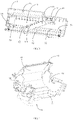
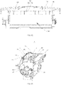
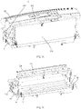
FIG. 1 is a partial structural schematic view of an embodiment of a movable air conditioner according to the present application. -
FIG. 2 is a schematic view of an assembly of a partition plate and a fixing structure inFIG. 1 . -
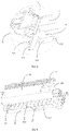
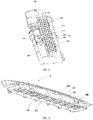
FIG. 3 is a schematic structural view of the partition plate inFIG. 1 . -
FIG. 4 is a schematic structural view of a volute (from a view angle) inFIG. 1 . -
FIG. 5 is an enlarged structural schematic view of portion A inFIG. 4 . -
FIG. 6 is a schematic structural view of the volute (from another viewing angle) inFIG. 1 . -
FIG. 7 is a partial structural view of the movable air conditioner according to the embodiment of the present application. -
FIG. 8 is a schematic structural view of a top air outlet plate of the movable air conditioner according to the embodiment of the present application. -
FIG. 9 is a partial structural view of the top air outlet plate of the movable air conditioner according to the embodiment of the present application. -
FIG. 10 is an enlarged view of portion B inFIG. 9 . -
FIG. 11 is another partial schematic structural view of the movable air conditioner according to an embodiment of the present application. -
FIG. 12 is a schematic structural view of another viewing angle ofFIG. 11 . -
FIG. 13 is a schematic structural view of the volute of the movable air conditioner according to the embodiment of the present application. -
FIG. 14 is a schematic structural view of a volute cover of the movable air conditioner according to the embodiment of the present application. -
FIG. 15 is an isometric structural view of a movable air conditioner according to the embodiment of the present application. -
FIG. 16 is an isometric structure view of the movable air conditioner ofFIG. 15 . -
FIG. 17 is an enlarged view of portion C inFIG. 16 . -
FIG. 18 is a schematic right view of the movable air conditioner ofFIG. 15 . -
FIG. 19 is an enlarged view of portion D inFIG. 18 . -
FIG. 20 is an isometric view of a part of the movable air conditioner ofFIG. 15 . -
FIG. 21 is an isometric view of a part of the movable air conditioner ofFIG. 15 . -
FIG. 22 is an exploded view of the movable air conditioner ofFIG. 21 . -
FIG. 23 is an enlarged view of portion E inFIG. 22 . -
FIG. 24 is an enlarged view of portion F inFIG. 22 . - Reference numerals of the drawings:
Reference numerals Name Reference numerals Name 1 Middle partition plate 231 Reinforcing rib 11 Water guide groove 24 Side plate 111 Water falling hole 241 First protrusion 12 Second blocking rib 242 Positioning groove 13 Flow shunting rib 243 Reinforcing plate 2 Volute 31 Supporting base 21 Air duct plate 32 First blocking rib 22 Wind deflector bottom plate 33 Second protrusion 221 Water blocking ridge 34 Side blocking protrusion 222 Wind deflector 35 Connecting column 23 Extension plate 200 Indoor side heat exchanger 100 Top air outlet plate 110 Indoor side air outlet 120 Mounting surrounding plate 121 First mounting plate 122 Second mounting plate 130 Clamping portion 131 Extension member 132 Protrusion member 140 First stop block 141 Guide surface 142 First insertion groove 150 First step 160 Second stop block 170 Air supply grille 171 Longitudinal grille bar 172 Transverse grille bar 211 First side edge 210 Air supply outlet 213 Clamping groove 212 Second side edge 220 Volute cover 214 Second step 222 Water conduct groove 221 Top plate 224 Second side wall 223 First side wall 226 First reinforcing rib 225 Bottom wall 230 Volute base 227 Second reinforcing rib 240 Air inlet 231 Third reinforcing rib 400 First clamping structure 500 Second clamping structure 60 Mounting groove 67 Fourth bending plate 61 Mounting protrusion 67a Clamping groove 62 First supporting protrusion 68 Connecting protrusion 63 Second supporting protrusion 70 First end plate 64 First bending plate 701 First flange 65 Second bending plate 71 Second end plate 66 Third bending plate 711 Second flange 66a Limiting groove 50 Housing - The implementation, function characteristics and advantages of the present application will be further described with reference to the accompanying drawings.
- The embodiments of the present application are clearly and completely described below with reference to the accompanying drawings in the embodiments of the present application. Obviously, the described embodiments are only a part of the embodiments of the present application, not all of the embodiments. All other embodiments obtained by a skilled in the art based on the embodiments of the present application without creative efforts shall fall within the claimed scope of the present application.
- It should be noted that, if the embodiments of the present application relate to directional indications (such as upper, lower, left, right, front, and rear...), the directional indications are only used to explain the relative position relationships, motion situations, etc. between the parts under a certain specific posture (as shown in the drawings), and if the specific posture changes, the directional indications change accordingly.
- In addition, the descriptions of the terms "first", "second" and the like in the embodiments of the present application are used for descriptive purposes only, and cannot be understood as indicating or implying relative importance or implicitly indicating the number of indicated technical features. Thus, features defined with "first" and "second" may explicitly or implicitly include at least one of the features. In addition, the meaning of "and/or" throughout the text includes three parallel solutions, taking "A and/or B" as an example, "A and/or B" includes solution A, or solution B, or both solutions A and B. In addition, the embodiments can be combined with each other, but must be based on that those skilled in the art can realize it. When the combination of the embodiments is contradictory or cannot be achieved, the combination of the embodiments should not be considered as being within the claimed scope of the present application.
- With the development of technology, the air conditioner has gradually become an indispensable home appliance in the daily life of people, and people's requirements on differentiation and multi-function are increasing. Currently, the movable air conditioner is generally provided with a heat exchanger and a volute inside the housing, and a heat exchange air channel communicating with the heat exchanger is formed in the volute. In the related art, the volute is directly screwed and fixed in the housing through screws, which has the defect that the installation is unstable.
- In view of the above, the present application provides a movable air conditioner, and
FIGS. 1-24 are specific embodiments of the movable air conditioner provided by the present application. - Referring to
FIG. 1, FIG. 2 andFIG. 15 , the present application provides a movable air conditioner, the movable air conditioner includes ahousing 50, amiddle partition plate 1 and avolute 2. Themiddle partition plate 1 is arranged in thehousing 50. Thevolute 2 is arranged in thehousing 50. Thevolute 2 and themiddle partition plate 1 are provided with a fixing structure, and the fixing structure is arranged around thevolute 2 to fix thevolute 2 on themiddle partition plate 1. - According to the embodiments provided by the invention, the
middle partition plate 1 can limit a downward movement of thevolute 2. By arranging the fixing structure around thevolute 2, thevolute 2 can be restricted to move in a circumferential direction, thus, good fixation of thevolute 2 in thehousing 50 is achieved, and the installation stability of thevolute 2 is improved. - It should be noted that, in this embodiment, the
middle partition plate 1 is arranged in a middle part of thehousing 50, so as to divide thehousing 50 into an indoor side cavity and an outdoor side cavity which are distributed along an up-down direction. The movable air conditioner includes an indoorside heat exchanger 200, an outdoor side heat exchanger (not shown in the figures) and an outdoor heat exchanging air duct (not labeled in the figures). The indoorside heat exchanger 200 is arranged in the indoor side cavity. An indoor side heat exchanging air duct is formed in thevolute 2 and includes an air inlet and an air outlet. The orientation of each of the air inlet and the air outlet can be any one in various orientations, but in this embodiment, the air inlet is optionally formed on one side of thevolute 2 close to the indoorside heat exchanger 200, and communicates with the indoorside heat exchanger 200, and the air outlet is formed at an upper end of thevolute 2. Therefore, a length of the indoor side heat exchanging air duct is prolonged. The outdoor side heat exchanger is arranged in the outdoor side cavity, the outdoor side heat exchanging air duct is communicated with the outdoor side heat exchanger and the indoor side heat exchanging air duct. The specific heat exchange principle of the movable air conditioner using the indoorside heat exchanger 200 and the outdoor side heat exchanger can make reference to the related art, and is not described in detail here. - In addition, the fixing structure is arranged around the
volute 2 in this design, that is, the fixing structure is arranged at a periphery of thevolute 2 along a circumferential direction of themiddle partition plate 1, and the fixing structure can be of a structure arranged along a circumferential direction of themiddle partition plate 1 without an interruption. In one embodiment, the fixing structure is specifically shown as an annular convex rib, and the annular convex rib is arranged on the periphery of thevolute 2. The annular convex rib and themiddle partition plate 1 cooperate to define a mounting groove. An inner size of the annular convex rib is matched with an outer contour size of a corresponding position of thevolute 2, so that the mounting groove can just clamp thevolute 2 and connect with thevolute 2, and the fixing and mounting of thevolute 2 are achieved. Of course, the fixing structure can be of a structure arranged along the circumferential direction of themiddle partition plate 1 with one or more interruptions. In another embodiment, the fixing structure is specifically shown as a plurality of convex blocks, and the plurality of convex blocks are distributed on the periphery of thevolute 2, so that good limiting of thevolute 2 can be achieved, and the advantages of being light and saving materials are also achieved. - Further, referring to
FIG. 1 to FIG. 3 , in this embodiment, thevolute 2 includes anair duct plate 21, theair duct plate 21 is formed on one side of thevolute 2 away from the indoorside heat exchanger 200, that is, the side of thevolute 2 away from the air inlet. Theair duct plate 21 is in an arc shape, so that a large space is formed in thevolute 2, and the indoor side heat exchanging air duct can be bent, and the heat exchanging effect can be enhanced. The fixing structure includes a supportingbase 31 protruded from themiddle partition plate 1, the supportingbase 31 is provided below theair duct plate 21 and abuts against theair duct plate 21, thereby restricting the movement of thevolute 2 in a direction away from the indoorside heat exchanger 200. Similarly, the supportingbase 31 can be of a structure arranged along a length direction of thevolute 2 without an interruption or with one or more interruptions. When the supportingbase 31 is arranged along the length direction of thevolute 2 without an interruption, the supportingbase 31 can extend along the length direction of thevolute 2 to abut against a whole lower end of thevolute 2, so as to enlarge an abutment area between the supportingbase 31 and thevolute 2. Of course, the supportingbase 31 can extend along the length direction of thevolute 2 to a part of the lower end of thevolute 2. At this time, since theair duct plate 21 is in an arc shape, a remaining part of a lower end of theair duct plate 21 is not abutted against the supportingbase 31, and is suspended above themiddle partition plate 1. Therefore, one or more cushion blocks (not shown in the figures) can be convexly arranged at the remaining section of themiddle partition plate 1 to fill space corresponding to the suspended position, so as to ensure the balance and stability of thevolute 2 on themiddle partition plate 1. - Next, in this embodiment, an upper end of the supporting
base 31 is provided with an abutting surface abutting against an outer wall surface of theair duct plate 21. A shape of the abutting surface is matched with a shape of the outer wall surface of theair duct plate 21. Based on the above, theair duct plate 21 in this embodiment is preferably in an arc shape, that is, the outer wall surface of theair duct plate 21 abutting against the abutting surface is in a convex arc surface shape. In this case, the abutting surface can be provided in a concave arc surface shape, and the abutment area between the supportingbase 31 and theair duct plate 21 can be increased with the male-female fitting between the convex arc surface and the concave arc surface. - In addition, in this embodiment, the
volute 2 further includes a winddeflector bottom plate 22, the winddeflector bottom plate 22 extends from the lower end of theair duct plate 21 to be away from theair duct plate 21. A shape of the winddeflector bottom plate 22 is adapted to a shape of a corresponding part of themiddle partition plate 1, for example, when themiddle partition plate 1 is in a flat plate shape at this part, the winddeflector bottom plate 22 is in a flat plate shape parallel to or approximately parallel to themiddle partition plate 1. The fixing structure further includes afirst blocking rib 32 protruded from themiddle partition plate 1. Thefirst blocking rib 32 is provided on one side of the winddeflector bottom plate 22 away from theair duct plate 21, and abuts against a side edge of the winddeflector bottom plate 22 away from theair duct plate 21. An extending direction of the first blockingrib 32 is identical to an extending direction of the side edge of the winddeflector bottom plate 22 away from theair duct plate 21, and the first blockingrib 32 may be exactly equal to or slightly higher than the side edge of the winddeflector bottom plate 22 in height. In this embodiment, the first blockingrib 32 is arranged to cooperate with the supportingbase 31, so that thevolute 2 can be effectively restricted to move close to or away from the indoorside heat exchanger 200. - In order to enlarge the space in the
volute 2 to increase an air inlet amount, referring toFIG. 5 , in this embodiment, thevolute 2 further includes anextension plate 23 arranged at the lower end of theair duct plate 21. Theextension plate 23 extends downwards, and the winddeflector bottom plate 22 is arranged at a lower end of theextension plate 23. Further, a plurality of reinforcingribs 231 can be provided at theextension plate 23. The plurality of reinforcingribs 231 extend along a width direction of theextension plate 23, and are arranged at intervals along a length direction of theextension plate 23, which helps to enhance the connection strength of theextension plate 23. - In addition, referring to
FIG. 3, FIG. 4 andFIG. 6 , in this embodiment, themiddle partition plate 1 is provided with awater guide groove 11 which is obliquely arranged. Thewater guide groove 11 is arranged above the outdoor side heat exchanger. Thefirst blocking rib 32 includes two sections distributed on two sides of thewater guide groove 11. An air leakage gap is formed between the two sections of the first blockingrib 32, and awater blocking ridge 221 is formed on the winddeflector bottom plate 22 corresponding to the air leakage gap. Thewater guide groove 11 is provided with a plurality ofwater falling holes 111 communicated with the indoor side cavity and the outdoor side cavity. The plurality ofwater falling holes 111 are arranged at intervals along a length direction of thewater guide groove 11, thewater guide groove 11 is arranged below thevolute 2, and is used for converging condensate water generated in the indoor side cavity to be output to the outdoor side cavity. The inclinedwater guide groove 11 helps to expand an area range of thewater guide groove 11 in the length direction of thevolute 2, thereby facilitating the rapid drainage. Then, thewater blocking ridge 221 correspondingly covers at least part of a notch of thewater guide groove 11, so that the condensate water in thewater guide groove 11 can be prevented from being reversely splashedinto thevolute 2. A length of thewater blocking ridge 221 can be set to be equal to a length of the air leakage gap, so that when thevolute 2 is installed on themiddle partition plate 1, the air leakage gap is exactly matched with thewater blocking ridge 221 in a male-female fitting manner to jointly form a watertight water blocking rib. The water blocking rib can not only block the condensate water from entering thevolute 2, but also strengthen the limiting effect of the first blockingrib 32 on thevolute 2. - In this embodiment, the
water blocking ridge 221 includes awind deflector 222 arranged on the side edge of the winddeflector bottom plate 22, and thewind deflector 222 protrudes downwards from the winddeflector bottom plate 22. That is, thewind deflector 222 protrudes from the winddeflector bottom plate 22 until being substantially flush with the lower end of the winddeflector bottom plate 22. Thewind deflector 222 can block wind from entering the lower end of the winddeflector bottom plate 22, while does not affect the condensate water entering thewater guide groove 11 from a position under thewater blocking ridge 221. - Based on the above, referring to
FIG. 2 andFIG. 3 , in this embodiment, at least onesecond blocking rib 12 is further provided on themiddle partition plate 1, the at least onesecond blocking rib 12 is disposed on one side of the first blockingrib 32 facing away from thevolute 2, and an extending direction of each second blockingrib 12 may be identical to that of the first blockingrib 32, and each second blockingrib 12 is provided with an opening for the condensate water to flow to thewater guide groove 11. Two adjacent second blockingribs 12 or the first blockingrib 32 and an adjacent second blocking rib form a drainage groove to allow the condensate water to flow through. The drainage groove formed between the first blockingrib 32 and thesecond blocking rib 12 is taken as an example, the drainage groove is arranged to be gradually inclined downwards in a direction towards thewater guide groove 11, so that the condensate water in the drainage groove is conveniently and thoroughly drained into thewater guide groove 11. In addition, the opening on thesecond blocking rib 12 can be arranged corresponding to thewater guide groove 11. Aflow shunting rib 13 can be convexly arranged between the opening and the air leakage gap, and theflow shunting rib 13 can be used for dispersing the condensate water from the opening to thewater guide groove 11, so that the condensate water is dispersed in thewater guide groove 11, and not accumulated at a certainwater falling hole 111 in thewater guide groove 11 to affect the drainage efficiency. - Referring to
FIG. 2 ,FIG. 3 andFIG. 6 , in this embodiment, thevolute 2 further includes twoside plates 24, the twoside plates 24 are distributed on two sides of theair duct plate 21, the two sides of theair duct plate 21 refer to two sides of theair duct plate 21 corresponding to the length direction of thevolute 2. The twoside plates 24, theair duct plate 21, theextension plate 23 and the winddeflector bottom plate 22 cooperate to form thevolute 2. Theside plate 24 is formed with afirst protrusion 241 protruded away from the winddeflector bottom plate 22. The fixing structure further includes asecond protrusion 33 protruded from themiddle partition plate 1. Thesecond protrusion 33 abuts against thefirst protrusion 241. It should be noted that the specific forms of thefirst protrusion 241 and thesecond protrusion 33 are not limited in the present design, for example, thefirst protrusion 241 may be protruded toward the indoorside heat exchanger 200, and thesecond protrusion 33 abuts against an outer side wall of thefirst protrusion 241, or thefirst protrusion 241 may protrude from theside plate 24 along the length direction of thevolute 2, and form a reinforcingplate 243 which is substantially parallel to an edge of a port of the air inlet. At this time, thesecond protrusion 33 is provided with a clamping groove, and the clamping groove is in fit with at least part of a side edge of thefirst protrusion 241 in a male-female fitting manner. In addition, according to different practical applications, thefirst protrusion 241 may be formed on at least one of the twoside plates 24, especially when there are twofirst protrusion 241 corresponding to the twoside plates 24, the limiting to thevolute 2 in the length direction of thevolute 2 can be reinforced. - When at least one of the two
side plates 24 is protruded from the winddeflector bottom plate 22 in a direction away from theair duct plate 21, a spigot is defined between the theside plate 24 and the winddeflector bottom plate 22, and the first blockingrib 32 is provided in the spigot so as to abut against the side edge of the winddeflector bottom plate 22 away from theair duct plate 21 as well as to abut against theside plate 24. Further, referring toFIGS. 2 ,4 and6 . In this embodiment, theside plate 24 is provided with apositioning groove 242, and the first blockingrib 32 is clamped in thepositioning groove 242. Compared with the design of the first blockingrib 32 directly abutting against theside plate 24, by means of the cooperation of the first blockingrib 32 and thepositioning groove 242, the connection strength between the first blockingrib 32 and theside plate 24 is enhanced, and thus the limiting effect of the first blockingrib 32 on thevolute 2 is enhanced. - In order to further enhance the limiting of the fixing structure to the
volute 2 along the length direction of thevolute 2, referring toFIG. 3 , in this embodiment, the fixing structure further includes aside blocking protrusion 34 provided on themiddle partition plate 1, theside blocking protrusion 34 is located on one side of theside plate 24 and abuts against theside plate 24. Theside blocking protrusion 34 may correspond to at least one of the twoside plates 24. Further, there may be a plurality ofside blocking protrusions 34 corresponding to eachside plate 24, and the plurality ofside blocking protrusions 34 are arranged at intervals along the width direction of thevolute 2. It should be noted that the specific form of eachside blocking protrusion 34 is not limited in this design. In one embodiment, theside blocking protrusion 34 can be a block, so that one side wall of theside blocking protrusion 34 directly abuts against thecorresponding side plate 24. Or in another embodiment, theside plate 24 can be provided with a limiting groove, and theside blocking protrusion 34 is engaged with the limiting groove in a male-female fitting manner. Or liking that in this embodiment, theside plate 24 can be provided with a limiting rib, theside blocking protrusion 34 is provided with a groove at a position corresponding to the limiting rib, and the groove is engaged with the limiting rib in a male-female fitting manner, so that an abutment area between thevolute 2 and theside blocking protrusion 34 is enlarged, and the mounting stability between thevolute 2 and theside blocking protrusion 34 is ensured. - In this embodiment, the fixing structure further includes a connecting
column 35. The connectingcolumn 35 is convexly arranged on themiddle partition plate 1, and connected with thevolute 2 through threads. Specifically, a mounting hole can be formed in the connectingcolumn 35, a threaded hole can be formed on thevolute 2 corresponding to the mounting hole. The fixing structure further includes a threaded member, and the threaded member passes through the mounting hole and then is connected with the threaded hole through threads, so that thevolute 2 is fixedly mounted on themiddle partition plate 1. It should be noted that, according to actual requirements, the connectingcolumn 35 in the present design may be disposed at any position along the circumferential direction of thevolute 2, and there may be one or more connectingcolumns 35 according to actual requirements, or a plurality of mounting holes may be provided on one connectingcolumn 35. In addition, when the threaded hole is set at a higher position of thevolute 2, a raised portion can be provided on themiddle partition plate 1, then the connectingcolumn 35 is convexly arranged on the raised portion, thereby avoiding to affect the connection strength of the connectingcolumn 35 by directly setting a longer connectingcolumn 35 on thevolute 2. - It should be noted that the
air duct plate 21, the winddeflector bottom plate 22, theside plate 24 and the like described above do not constitute a limitation on the specific shape of thevolute 2. Taking theside plate 24 as an example, theside plate 24 may be directly connected to the winddeflector bottom plate 22, or as shown inFIG. 2 , theside plate 24 is connected to the winddeflector bottom plate 22 through a step portion, which not only helps to form a mounting structure for mounting other components in thevolute 2, but also increases the connection strength between theside plate 24 and the winddeflector bottom plate 22. - In an embodiment, as shown in
FIGS. 7 ,8 ,13 and15 , thehousing 50 includes a topair outlet plate 100. The topair outlet plate 100 is provided with an indoorside air outlet 110. A peripheral edge of the indoorside air outlet 110 is provided with amounting surrounding plate 120 protruding inwards. - The
volute 2 is provided with anair supply outlet 210. Theair supply outlet 210 is provided corresponding to the indoorside air outlet 110, and themounting surrounding plate 120 is clamped to a periphery of theair supply outlet 210. - A fan air duct is formed in the
volute 2. The indoor air flows from the fan air duct to theair supply outlet 210, and enters a room through the indoorside air outlet 110 of the topair outlet plate 100. In the present application, through setting a mounting surrounding plate on the periphery of theair supply outlet 210 and the mounting surrounding plate protruding toward an inner side of theair supply outlet 210, and further themounting surrounding plate 120 clamping with the periphery of theair supplying outlet 210, it is convenient to align the indoorside air outlet 110 with the air supply outlet of thevolute 2, thus, the connection stability and installation convenience of thehousing 50 and thevolute 2 can be improved, and the sealing between the indoorside air outlet 110 and theair supply outlet 210 of thevolute 2 can be improved, the air leakage is prevented, the air loss is reduced, and noise caused by the air leakage is reduced. During installation, it only needs to align the indoorside air outlet 110 of the topair outlet plate 100 of thehousing 50 with theair supply outlet 210 of thevolute 2, and then complete the installation through clamping, which facilitates the disassembling and assembling and improves the working efficiency. - Specifically, as shown in
FIGS. 8 ,11 ,12 and 13 , themounting surrounding plate 120 includes afirst mounting plate 121 and asecond mounting plate 122 opposite to the first mountingplate 121, the first mountingplate 121 and thesecond mounting plate 122 extend along a length direction of the indoorside air outlet 110, and the periphery of theair supply outlet 210 includes afirst side edge 211 and asecond side edge 212 opposite to thefirst side edge 211. Thefirst mounting plate 121 is connected to thefirst side edge 211 through afirst clamping structure 400, and/or thesecond mounting plate 122 is connected to thesecond side edge 212 through asecond clamping structure 500. The indoorside air outlet 110 is clamped with the periphery of theair supply outlet 210 in the length direction, so that the connection stability between themounting surrounding plate 120 and the periphery of theair supply outlet 210 can be improved. It can be that only one side of themounting surrounding plate 120 is clamped with theair supply outlet 210, or be that two opposite sides of themounting surrounding plate 120 are clamped with theair supply outlet 210. Of course, the structure of the first mountingplate 121 engaging with thefirst side edge 211 and thesecond mounting plate 122 engaging with thesecond side edge 212 has a better sealing performance. - More specifically, as shown in
FIGS. 8-13 , an outer side surface of the first mountingplate 121 is provided with a clampingportion 130, an outer wall surface of thefirst side edge 211 is provided with a clampinggroove 213, and the clampingportion 130 is clamped with the clampinggroove 213. In this embodiment, there are two clampingportions 130, and each clampingportion 130 is a buckle. As shown inFIG. 10 , the buckle includes anextension member 131 and aprotrusion member 132. Theextension member 131 is bent and protrudes downward from the first mountingplate 121. Theprotrusion member 132 is protruded outwards from theextension member 131. Theextension member 131 has elasticity. In the installation process, theextension member 131 is pressed towards the first mountingplate 121 by the clampinggroove 213, after theprotrusion member 132 passes through the clampinggroove 213, theextension member 131 is restored. Theprotrusion member 132 abuts against a lower end of the clampinggroove 213 to prevent the buckle from coming out of the clampinggroove 213. In other embodiments, the clampingportion 130 may be a hook engaging with the clampinggroove 213, and there may be one ormore clamping portions 130. The clampingportion 130 may be provided on thefirst side edge 211, and the clampinggroove 213 is correspondingly provided on the first mountingplate 121. - A lower end of the
mounting surrounding plate 120 is inserted into theair supply outlet 210. As shown inFIG. 9 andFIG. 13 , afirst step 150 recessed inwards is formed at the lower end of themounting surrounding plate 120, and asecond step 214 is formed on the periphery of theair supply outlet 210 of thevolute 2. Thefirst step 150 and thesecond step 214 are spliced, so that the lower end of themounting surrounding plate 120 can be inserted into theair supply outlet 210, and the sealing between the indoorside air outlet 110 and theair supply outlet 210 of thevolute 2 is further improved. - Further, as shown in
FIGS. 8 to 11 , the outer side surface of the first mountingplate 121 is provided with afirst stop block 140. Afirst insertion groove 142 is formed between a lower end of thefirst stop block 140 and the first mountingplate 121, and an upper end of thefirst side edge 211 is inserted into thefirst insertion groove 142. The lower end of thefirst stop block 140 abuts against the outer wall surface of thefirst side edge 211, which further improves the sealing between the first mountingplate 121 and thefirst side edge 211. - Further, as shown in
FIG. 10 , aninclined guide surface 141 is formed on an inner side of the lower end of thefirst stop block 140, so as to guide the upper end of thefirst side edge 211 to be inserted into thefirst insertion groove 142. When assembling the topair outlet plate 100 of thehousing 50 with thevolute 2, the upper end of thefirst side edge 211 can slide into thefirst insertion groove 142 along theguide surface 141, thus to facilitate the assembling. There are a plurality of first stop blocks 140, and the plurality of first stop blocks 140 are arranged on the first mountingplate 121 at intervals to improve the sealing between the first mountingplate 121 and thefirst side edge 211. - In one embodiment of the present application, as shown in
FIG. 8, FIG. 9 andFIG. 12 , an outer side surface of thesecond mounting plate 122 is provided with asecond stop block 160, and a second insertion groove (not shown in the figures, and reference can be made to the structure of the first insertion groove 142) is formed between a lower end of thesecond stop block 160 and thesecond mounting plate 122. An upper end of thesecond side edge 212 is inserted into the second insertion groove. Thesecond stop block 160 is identical to thefirst stop block 140 in structure, and aninclined guide surface 141 is also formed at the lower end of thesecond stop block 160, so as to guide the upper end of thesecond side edge 212 to be inserted into the second insertion groove. There are a plurality of second stop blocks 160, and the plurality of second stop blocks 160 are arranged on thesecond mounting plate 122 at intervals to improve the sealing between thesecond mounting plate 122 and thesecond side edge 212. - As shown in
FIGS. 13 and14 , thevolute 2 includes avolute 230 and avolute cover 220, and thevolute 230 is connected to thevolute cover 220 to form theair supply outlet 210. Thevolute cover 220 includes atop plate 221, and awater conduct groove 222 extending in a length direction of thetop plate 221 is provided on thetop plate 221. Thewater conduct groove 222 includes abottom wall 225 and afirst side wall 223 and asecond side wall 224 both connected to thebottom wall 225. Thefirst side wall 223 and thesecond side wall 224 are opposite to each other, and thefirst side wall 223 is further used for forming theair supply outlet 210. As shown inFIG. 7 , the movable air conditioner of this embodiment further includes an indoor side heat exchanger 300 located below thetop plate 221, thevolute 2 is formed with anair inlet 240 corresponding to the indoor side heat exchanger 300. Theair supply outlet 210 and the indoorside air outlet 110 are both located at the top of the housing. When air is discharged from the top, the condensate water is converged into thewater conduct groove 222, the situation that the condensate water flows into the inner side heat exchanger 300 and thevolute 2 is avoided. - The
water conduct groove 222 further includes a first reinforcingrib 226. The first reinforcingrib 226 is connected to thebottom wall 225 and thefirst side wall 223, and the first reinforcingrib 226 is spaced apart from thesecond side wall 224. An upper end of the first reinforcingrib 226 is protruded from thefirst side wall 223 to abut against the outer side surface of thesecond mounting plate 122 of themounting surrounding plate 120. The first reinforcingrib 226 not only can strengthen the strength of thewater conduct groove 222, for the upper end of the first reinforcingrib 226 can abut against the outer side face of thesecond mounting plate 122, the first reinforcingrib 226 also improves the sealing between the indoorside air outlet 110 and theair supply outlet 210 of thevolute 2. Thewater conduct groove 222 of this embodiment further includes a second reinforcingrib 227. The second reinforcingrib 227 is connected to thebottom wall 225 and thesecond side wall 224, and the second reinforcingrib 227 is spaced apart from thefirst side wall 223. The second reinforcingrib 227 is opposite to the first reinforcingrib 226 to form a water passing groove for the condensate water to pass through. - As shown in
FIG. 11 andFIG. 13 , thevolute 230 is provided with a third reinforcingrib 231, and an upper end of the third reinforcingrib 231 is protruded from thefirst side edge 212 of theair supply outlet 210 to abut against the outer side surface of the first mountingplate 121 of themounting surrounding plate 120. The third reinforcingrib 231 not only strengthens the strength of thevolute 230, for the upper end of the third reinforcingrib 231 can be clamped on the outer side surface of the first mountingplate 121 of themounting surrounding plate 120, the third reinforcingrib 231 also improves the sealing between the indoorside air outlet 110 and theair supply outlet 210 of thevolute 2. - As shown in
FIG. 7 , anair supply grille 170 is formed at the indoorside air outlet 110 of this embodiment, theair supply grille 170 includes an inner grille and an outer grille, the inner grille includes longitudinal grille bars 171 and transverse grille bars 172 intersecting with the longitudinal grille bars 171. The longitudinal grille bars 171 is protruded outwards to beyond thetransverse grid bar 172 to form the outer grille. The crisscross inner grille can make the air more uniform and have a dustproof effect, and the outer grille is more attractive and has the effect of wind guiding and reducing air loss. - In one embodiment, referring to
FIG. 15 andFIG. 16 , thevolute 2 is mounted in thehousing 50, and thevolute 2 is mounted on themiddle partition plate 1. Thevolute 2 is provided with theair inlet 240. The movable air conditioner further includes the indoorside heat exchanger 200, and the indoorside heat exchanger 200 is mounted in thehousing 50 and on themiddle partition plate 1. The indoorside heat exchanger 200 is arranged on an air inlet side of thevolute 2, and the indoorside heat exchanger 200 is connected to the side edge of theair inlet 240 through a clamping structure and/or a threaded connection structure. - In the embodiments of the present application, the indoor
side heat exchanger 200 is not only arranged on themiddle partition plate 1, but also connected to the side edge of theair inlet 240 through a clamping structure and/or a threaded connection structure, the indoorside heat exchanger 200 is limited at multiple positions, thus the indoorside heat exchanger 200 is more stable and has a better effect. - The side edge of the
air inlet 240 includes a third side edge and a fourth side edge opposite to the third side edge in a length direction of theair inlet 240, the mounting structure can be arranged at the third side edge or at the fourth side edge, or each of the third side edge and the fourth side edge is provided with a mounting structure. In the following the mounting structure being only at the third side edge or the fourth side edge is taken as an example. - In one embodiment, referring to
FIG. 16 and FIG. 17 , thevolute 2 further includes afirst bending plate 64 connected to the third side edge and bent towards the fourth side edge. One end of the indoorside heat exchanger 200 is provided with afirst end plate 70, and thefirst end plate 70 is connected to thefirst bending plate 64 through a clamping structure and/or a threaded connection structure, thus the indoorside heat exchanger 200 can be fixed at the third side edge only by connecting thefirst bending plate 64 with thefirst end plate 70, which facilitates not only the arrangement of the clamping structure and/or the threaded connection structure but also the installation of the indoorside heat exchanger 200. - In another embodiment, referring to
FIG. 18 and FIG. 19 , the side edge of theair inlet 240 includes the third side edge and the fourth side edge opposite to the third side edge in the length direction of theair inlet 240. Thevolute 2 further includes asecond bending plate 65 connected to the fourth side edge and bent towards the third side edge. Thesecond end plate 71 is connected with thesecond bending plate 65 through a clamping structure and/or a threaded connection structure, thus thesecond bending plate 65 can be fixed at the fourth side edge, which facilitates not only the arrangement of the clamping structure and/or the threaded connection structure but also the installation of the indoorside heat exchanger 200. - Further, in one embodiment, referring to
FIG. 21 to FIG. 23 , thevolute 2 further includes athird bending plate 66 connected to a tail end of thefirst bending plate 64 and bent towards the indoorside heat exchanger 200. Thefirst end plate 70 is protruded laterally beyond the indoorside heat exchanger 200 to be connected with thethird bending plate 66. By bending further to form thethird bending plate 66, the arrangement of the clamping structure and/or the threaded connection structure is facilitated. - The mounting manner of mounting the
third bending plate 66 with thefirst end plate 70 may be through a clamping structure or through a threaded connection structure, or through a form combining the two structures, and in the following, the situation of only the clamping structure or the threaded structure being provided is described. - In one embodiment, referring to
FIG. 21 ,FIG. 22 andFIG. 24 , thefirst end plate 70 and thethird bending plate 66 are connected through a threaded connection structure, for example, a flange hole may be formed on one of thefirst end plate 70 and thethird bending plate 66, an internal thread is provided in the flange hole, a connecting hole is provided on the other one of thefirst end plate 70 and thethird bending plate 66. A threaded end of a threaded member passes through the connecting hole to be fixed in the flange hole, thus the structure is simple and the installation is facilitated. - It should be noted that in this embodiment, being away from the air inlet of the
volute 2 is facing outwards, and being closing to the air inlet of thevolute 2 is facing inwards. Thefirst end plate 70 is arranged on an outer side of thethird bending plate 66, as such, a flange is not needed to be provided on thefirst end plate 70, which facilitates thefirst end plate 70 to be attached to thethird bending plate 66 and further facilitates the installation of the indoorside heat exchanger 200. - In one embodiment, referring to
FIGS. 22 and23 , thethird bending plate 66 is recessed inwards to form a limitinggroove 66a, afirst flange 701 is formed at a tail end of thefirst end plate 70, and thefirst flange 701 is clamped in the limitinggroove 66a. Through the limitinggroove 66a engaging with thefirst flange 701, a better limiting effect and a more stable installation are obtained. - With regard to the mounting structure at the fourth side edge, in one embodiment, the
volute 2 further includes afourth bending plate 67 connected to a tail end of thesecond bending plate 65 and bent towards the indoorside heat exchanger 200. Thesecond end plate 71 is protruded laterally to beyond the indoorside heat exchanger 200 to be connected with thefourth bending plate 67. By bending further to form thefourth bending plate 67 at the fourth side edge, the indoorside heat exchanger 200 can be fixed more stably. - Further, in one embodiment, the mounting manner of mounting the
fourth bending plate 67 with thesecond end plate 71 may be through a clamping structure or through a threaded connection structure, or through a form combining the two structures, and in the following, the situation of only the clamping structure or the threaded structure being provided is described. - In one embodiment, the
second end plate 71 and thefourth bending plate 67 are connected through a threaded connection structure, for example, a flange hole can be formed on one of thesecond end plate 71 and thefourth bending plate 67, an internal thread is provided in the flanging hole, a connecting hole is provided on the other one of thesecond end plate 71 and thefourth bending plate 67. A threaded end of a threaded member passes through the connecting hole to be fixed in the flange hole, thus the structure is simple and the installation is facilitated. - It should be noted that in this embodiment, being away from the air inlet of the
volute 2 is facing outwards, and being closing to the air inlet of thevolute 2 is facing inwards. Thesecond end plate 71 is arranged on an outer side of thefourth bending plate 67, as such, a flange is not needed to be provided on thesecond end plate 71, which facilitates thesecond end plate 71 to be attached to the fourth bending plate 67and further facilitates the the installation of the indoorside heat exchanger 200. - In one embodiment, referring to
FIG. 22 andFIG. 24 , a clampinggroove 67a is formed at a tail end of thefourth bending plate 67, asecond flange 711 is formed at a tail end of thefirst end plate 70, and thesecond flange 711 is clamped in the clampinggroove 67a. Through the clampinggroove 67a engaging with thesecond flange 711, a better limiting effect and a more stable installation are obtained. - After limiting the indoor
side heat exchanger 200 along the length direction of theair inlet 240, in order to further limit and fix the indoorside heat exchanger 200, in one embodiment, thevolute 2 includes avolute base 230 and avolute cover 220 connected to thevolute base 230. Thevolute cover 220 includes thetop plate 221, and thetop plate 221 is extended towards the indoorside heat exchanger 200 and provided above the indoorside heat exchanger 200. Thetop plate 221 is connected to the indoorside heat exchanger 200 through a clamping structure and/or a threaded connection structure, thus the indoorside heat exchanger 200 is limited in the width direction of theair inlet 240, and a better limiting effect and a more stable installation are obtained. - Specifically, referring to
FIG. 17 andFIG. 19 , a connectingprotrusion 68 is provided under thetop plate 221. The connectingprotrusion 68 is connected to thesecond end plate 71 of the indoorside heat exchanger 200 through a threaded connection structure, for example, a threaded hole may be formed on one of the connectingprotrusion 68 and thefourth bending plate 67, a connecting hole is provided on the other one of the connectingprotrusion 68 and thefourth bending plate 67, and a threaded end of a threaded member passes through the connecting hole to be fixed in the threaded hole, thus the structure is simple, and the installation is facilitated. - In the embodiments of the present application, the
middle partition plate 1 serves as a structure for bearing the indoorside heat exchanger 200 and needs to install the indoorside heat exchanger 200. In one embodiment, referring toFIG. 22 , themiddle partition plate 1 is provided with a mountinggroove 60 and awater guide groove 11 communicated with the mountinggroove 60. Thewater guide groove 11 is arranged below thevolute 2 and corresponds to the outdoor side heat exchanger. A bottom of the mounting groove is inclined toward thewater guide groove 11. The indoorside heat exchanger 200 is mounted in the mountinggroove 60, and the indoorside heat exchanger 200 is inclined toward thevolute 2. By inclining the outdoorside heat exchanger 200, a heat exchange area can be increased, and the heat exchange effect is improved. - The
middle partition plate 1 is located below the indoorside heat exchanger 200. In order to further limit the indoorside heat exchanger 200, in one embodiment, themiddle partition plate 1 is convexly provided with a mountingprotrusion 61. The mountingprotrusion 61 is provided on an air inlet side of the indoorside heat exchanger 200, and the mountingprotrusion 61 is connected to an end plate of the indoorside heat exchanger 200, as such, a side of the indoorside heat exchanger 200 away from the air inlet is limited, and the installation stability of the indoorside heat exchanger 200 is further improved. - In one embodiment, a first supporting
protrusion 62 is arranged on themiddle partition plate 1, and the first supportingprotrusion 62 is arranged on the air inlet side of the indoorside heat exchanger 200, the first supportingprotrusion 62 is spliced with a first bending portion of thevolute 2, the first supportingprotrusion 62 limits a side end of the indoor side heat exchanger, and the installation stability of the indoorside heat exchanger 200 is further improved. - In one embodiment, a second supporting
protrusion 63 is arranged on themiddle partition plate 1, the second supportingprotrusion 63 is arranged on the air inlet side of the indoorside heat exchanger 200, the second supportingprotrusion 63 is spliced with a second bending portion of thevolute 2, the first supportingprotrusion 62 limits another side end of the indoor side heat exchanger, and the installation stability of the indoorside heat exchanger 200 is further improved. - It should be noted that any one of or all of the mounting
protrusion 61, the first supportingprotrusion 62 and the second supportingprotrusion 63 can be selected for limiting the indoorside heat exchanger 200, of course, when the mountingprotrusion 61, thefirst support protrusion 62 and thesecond support protrusion 63 are all provided, the installation of the indoorside heat exchanger 200 is more stable. - The above is only an optional embodiment of the present application, and is not therefore intended to limit the scope of the present application. Any equivalent structure or equivalent process transformation made using the description and drawings of the present application, or any direct or indirect application to other related technical fields, is included in the claimed scope of the present application.
Claims (20)
- A movable air conditioner characterized by comprising:a housing;a middle partition plate arranged in the housing; anda volute arranged in the housing,wherein a fixing structure is arranged on the volute and the middle partition plate, the fixing structure surrounding the volute and configured to fix the volute on the middle partition plate.
- The movable air conditioner according to claim 1, wherein the volute comprises an air duct plate in an arc shape,the fixing structure comprises a supporting base protruded from the middle partition plate and arranged below the air duct plate, the supporting base abutting against the air duct plate; and/orthe fixing structure comprises a connecting column convexly arranged on the middle partition plate, the connecting column being in threaded connection with the volute.
- The movable air conditioner according to claim 2, wherein,an upper end of the supporting base is provided with an abutting surface abutting against an outer wall surface of the air duct plate, and a shape of the abutting surface is matched with a shape of the outer wall surface of the air duct plate; and/orthe volute further comprises a wind deflector bottom plate extending from a lower end of the air duct plate to be away from the air duct plate, and the fixing structure further comprises a first blocking rib protruded from the middle partition plate and arranged on one side of the wind deflector bottom plate away from the air duct plate, the first blocking rib abutting against a side edge of the wind deflector bottom plate away from the air duct plate.
- The movable air conditioner according to claim 3, wherein,the volute further comprises an extension plate arranged at the lower end of the air duct plate and extending downwards, and the wind deflector bottom plate is arranged at the lower end of the extension plate; and/orthe middle partition plate is provided with a water guide groove obliquely arranged and configured for being arranged above an outdoor side heat exchanger, the first blocking rib comprises two sections distributed on two sides of the water guide groove, an air leakage gap is formed between the two sections of the first blocking rib, and a water blocking ridge is formed on the wind deflector bottom plate corresponding to the air leakage gap.
- The movable air conditioner according to claim 4, wherein the water blocking ridge comprises a wind deflector arranged on the side edge of the wind deflector bottom plate and protrudes downwards to beyond the wind deflector bottom plate.
- The movable air conditioner according to claim 3, wherein the volute further comprises two side plates distributed on two sides of the air duct plate, and each side plate is formed with a first protrusion protruded away from the wind deflector bottom plate, the fixing structure further comprises a second protrusion protruded from the middle partition plate and abutting against the first protrusion.
- The movable air conditioner according to claim 6, wherein,each side plate is provided with a positioning groove, and the first blocking rib is clamped in the positioning groove; and/orthe fixing structure further comprises a side blocking protrusion arranged on the middle partition plate and located on one side of the side plate, the side blocking protrusion abutting against the side plate.
- The movable air conditioner according to claim 1, wherein,the housing further comprises a top air outlet plate provided with an indoor side air outlet, and a circumferential edge of the indoor side air outlet is convexly provided with a mounting surrounding plate; andthe volute has an air supply outlet arranged corresponding to the indoor side air outlet, and the mounting surrounding plate is clamped to a periphery of the air supply outlet.
- The movable air conditioner according to claim 8, wherein,the mounting surrounding plate comprises a first mounting plate and a second mounting plate opposite to the first mounting plate, the first mounting plate and the second mounting plate extending along a length direction of the indoor side air outlet, and the periphery of the air supply outlet comprises a first side edge and a second side edge opposite to the first side edge;the first mounting plate is connected with the first side edge through a first clamping structure; and/or the second mounting plate is connected with the second side edge through a second clamping structure.
- The movable air conditioner according to claim 9, wherein,a clamping portion is arranged on an outer side surface of the first mounting plate, a clamping groove is formed on an outer wall surface of the first side edge, and the clamping portion is clamped in the clamping groove; and/ora lower end of the mounting surrounding plate is inserted in the air supply outlet.
- The movable air conditioner according to claim 10, wherein,a first stop block is arranged on the outer side surface of the first mounting plate, a first insertion groove is formed between a lower end of the first stop block and the first mounting plate, and an upper end of the first side edge is inserted in the first insertion groove; and/ora second stop block is arranged on an outer side surface of the second mounting plate, a second insertion groove is formed between a lower end of the second stop block and the second mounting plate, and an upper end of the second side edge is inserted in the second insertion groove.
- The movable air conditioner according to claim 11, wherein an inclined guide surface is formed on an inner side of the lower end of the first stop block, and configured to guide the upper end of the first side edge to be inserted in the first insertion groove.
- The movable air conditioner according to any one of claims 8 to 10, wherein,the volute comprises a volute base and a volute cover, and the volute base is connected to the volute cover to form the air supply outlet, the volute cover comprises a top plate, and a water conduct groove is formed on the top plate and extending in a length direction of the top plate; the water conduct groove comprises a bottom wall and a first side wall and a second side wall both connected with the bottom wall, the first side wall is opposite to the second side wall, and the first side wall is further configured for forming the air supply outlet; and/oran air supply grille is formed at the indoor side air outlet, the air supply grille comprises an inner grille and an outer grille, the inner grille comprises longitudinal grille bars and transverse grille bars intersecting with the longitudinal grille bars, and the longitudinal grille bars are protruded outwards to beyond the transverse grille bars to form the outer grille.
- The movable air conditioner according to claim 13, wherein,the water conduct groove further comprises a first reinforcing rib connected with the bottom wall and the first side wall and spaced apart from the first side wall, an upper end of the first reinforcing rib being protruded from the first side wall to abut against the outer side surface of the second mounting plate of the mounting surrounding plate; and/orthe volute base is provided with a third reinforcing rib, and an upper end of the third reinforcing rib is protruded from the first side edge of the air supply outlet and configured to abut against the outer side surface of the first mounting plate of the mounting surrounding plate.
- The movable air conditioner according to claim 1, wherein,the volute is mounted in the housing and has an air inlet;the movable air conditioner comprises an indoor side heat exchanger installed in the housing and on the middle partition plate, the indoor side heat exchanger is arranged on an air inlet side of the volute, and the indoor side heat exchanger is connected with a side edge of the air inlet through a clamping structure and/or a threaded connection structure.
- The movable air conditioner according to claim 15, wherein the side edge of the air inlet comprises a third side edge and a fourth side edge opposite to the third side edge in a length direction of the air inlet,the volute further comprises a first bending plate connected to the third side edge and bent towards the fourth side edge direction, and a first end plate is arranged at one end of the indoor side heat exchanger and connected with the first bending plate through a clamping structure and/or a threaded connection structure; and/orthe volute further comprises a second bending plate connected to the fourth side edge and bent towards the third side edge, and a second end plate is arranged at another end of the indoor side heat exchanger and connected with the second bending plate through a clamping structure and/or a threaded connection structure.
- The movable air conditioner according to claim 16, wherein,the volute further comprises a third bending plate connected to a tail end of the first bending plate and bent towards the indoor side heat exchanger, and the first end plate is protruded laterally beyond the indoor side heat exchanger to be connected with the third bending plate; and/orthe volute further comprises a fourth bending plate connected to a tail end of the second bending plate and bent towards the indoor side heat exchanger, and the second end plate is protruded laterally beyond the indoor side heat exchanger to be connected with the fourth bending plate.
- The movable air conditioner according to claim 17, wherein,the first end plate and the third bending plate are connected through a threaded connection structure; and/orthe third bending plate is recessed inwards to form a limiting groove, a first flange is formed at a tail end of the first end plate and clamped in the limiting groove; and/orthe second end plate is connected with the fourth bending plate through a threaded connection structure; and/ora clamping groove is formed at a tail end of the fourth bending plate, a second flange is formed at a tail end of the second end plate and clamped in the clamping groove.
- The movable air conditioner according to any one of claims 15 to 18, wherein,the volute comprises a volute base and a volute cover engaged with the volute base, the volute cover comprises a top plate arranged above the indoor side heat exchanger and extending towards the indoor side heat exchanger, and the top plate is connected with the indoor side heat exchanger through a clamping structure and/or a threaded connection structure; and/orthe middle partition plate is provided with a mounting groove and a water guide groove communicated with the mounting groove, the water guide groove is arranged below the indoor side air housing and corresponds to an outdoor side heat exchanger of the movable air conditioner, a bottom of the mounting groove is inclined toward the water guide groove, the indoor side heat exchanger is installed in the mounting groove and inclined toward the indoor side air housing; and/orthe middle partition plate is convexly provided with a mounting protrusion, the mounting protrusion is arranged on an air inlet side of the indoor side heat exchanger and connected with an end plate of the indoor side heat exchanger; and/orthe middle partition plate is convexly provided with a first supporting protrusion, the first supporting protrusion is arranged on the air inlet side of the indoor side heat exchanger and spliced with a first bending portion of the volute; and/orthe middle partition plate is convexly provided with a second supporting protrusion, the second supporting protrusion is arranged on the air inlet side of the indoor side heat exchanger and spliced with a second bending portion of the volute.
- The movable air conditioner according to claim 19, wherein a connecting protrusion is provided below the top plate, and the connecting protrusion is connected with the second end plate of the indoor side heat exchanger through a threaded connecting structure.
Applications Claiming Priority (4)
| Application Number | Priority Date | Filing Date | Title |
|---|---|---|---|
| CN201921942541.0U CN210832282U (en) | 2019-11-11 | 2019-11-11 | Mobile air conditioner |
| CN201921941615.9U CN210832286U (en) | 2019-11-11 | 2019-11-11 | Mobile air conditioner |
| CN201921948200.4U CN210921601U (en) | 2019-11-11 | 2019-11-11 | mobile air conditioner |
| PCT/CN2020/081453 WO2021093252A1 (en) | 2019-11-11 | 2020-03-26 | Movable air conditioner |
Publications (4)
| Publication Number | Publication Date |
|---|---|
| EP4043806A1 true EP4043806A1 (en) | 2022-08-17 |
| EP4043806A4 EP4043806A4 (en) | 2022-12-07 |
| EP4043806B1 EP4043806B1 (en) | 2025-05-28 |
| EP4043806C0 EP4043806C0 (en) | 2025-05-28 |
Family
ID=75911944
Family Applications (1)
| Application Number | Title | Priority Date | Filing Date |
|---|---|---|---|
| EP20887781.1A Active EP4043806B1 (en) | 2019-11-11 | 2020-03-26 | Movable air conditioner |
Country Status (2)
| Country | Link |
|---|---|
| EP (1) | EP4043806B1 (en) |
| WO (1) | WO2021093252A1 (en) |
Family Cites Families (16)
| Publication number | Priority date | Publication date | Assignee | Title |
|---|---|---|---|---|
| US6339935B1 (en) * | 2001-05-16 | 2002-01-22 | Carrier Corporation | Evaporator scroll for blower wheel |
| KR100419197B1 (en) * | 2001-11-08 | 2004-02-19 | 삼성전자주식회사 | One Unit Type Air Conditioner |
| KR20040063670A (en) * | 2003-01-08 | 2004-07-14 | 엘지전자 주식회사 | Blower hausing mounting structure for unitary type airconditioner |
| JP4516037B2 (en) * | 2006-03-08 | 2010-08-04 | シャープ株式会社 | Air conditioner |
| CN101929712A (en) * | 2009-06-22 | 2010-12-29 | 乐金电子(天津)电器有限公司 | Annular mobile air conditioner |
| CN102003747A (en) * | 2009-08-28 | 2011-04-06 | 乐金电子(天津)电器有限公司 | Movable type air conditioner |
| JP2015175528A (en) * | 2014-03-13 | 2015-10-05 | 三菱重工業株式会社 | integrated air conditioner |
| JP6311427B2 (en) * | 2014-04-18 | 2018-04-18 | ダイキン工業株式会社 | Air conditioner |
| CN106461238A (en) * | 2014-06-05 | 2017-02-22 | 三星电子株式会社 | Integrated air conditioner |
| CN106403239B (en) * | 2016-10-31 | 2021-09-21 | 芜湖美智空调设备有限公司 | Single-through-flow air conditioner capable of ejecting air and control method |
| CN206637750U (en) * | 2017-04-12 | 2017-11-14 | 上海合和实业有限公司 | A kind of safe and efficient air conditioner for elevator |
| CN109425029A (en) * | 2017-08-18 | 2019-03-05 | 广东美的制冷设备有限公司 | Air conditioner integrated machine |
| CN207584932U (en) * | 2017-09-30 | 2018-07-06 | 青岛海尔空调器有限总公司 | Integrated air conditioner |
| CN109611954A (en) * | 2017-09-30 | 2019-04-12 | 青岛海尔空调器有限总公司 | Window air conditioner |
| CN108870552B (en) * | 2018-04-28 | 2023-07-14 | 奥克斯空调股份有限公司 | Mobile air conditioner |
| CN209180077U (en) * | 2018-12-11 | 2019-07-30 | 广东美的制冷设备有限公司 | Blower, fresh air module and air conditioner |
-
2020
- 2020-03-26 WO PCT/CN2020/081453 patent/WO2021093252A1/en not_active Ceased
- 2020-03-26 EP EP20887781.1A patent/EP4043806B1/en active Active
Also Published As
| Publication number | Publication date |
|---|---|
| EP4043806B1 (en) | 2025-05-28 |
| WO2021093252A1 (en) | 2021-05-20 |
| EP4043806C0 (en) | 2025-05-28 |
| EP4043806A4 (en) | 2022-12-07 |
Similar Documents
| Publication | Publication Date | Title |
|---|---|---|
| US6471739B2 (en) | Dehumidifier housing | |
| US11054151B2 (en) | Indoor unit for air conditioner | |
| US11578879B2 (en) | Window-type air conditioner | |
| US12584639B2 (en) | Electric control box, air conditioning outdoor unit, air conditioner and method for assembling electric control box | |
| EP4043806B1 (en) | Movable air conditioner | |
| CN215637621U (en) | Air duct shell assembly and window type air conditioner | |
| CN223242884U (en) | Mobile air conditioner | |
| WO2022205871A1 (en) | Cabinet-type air conditioner indoor unit and cabinet-type air conditioner | |
| US11614257B2 (en) | Housing assembly for air handling apparatus and air handling apparatus | |
| CN108278678B (en) | Mounting assembly of air conditioner hanging machine, air conditioner hanging machine assembly and air conditioner | |
| CN216897576U (en) | Heat exchange structure and outdoor unit | |
| CN113738667A (en) | Volute assembly and air conditioner | |
| CN212376921U (en) | Volute assembly and air conditioner | |
| CN211822790U (en) | Air conditioner indoor unit and air conditioner | |
| CN211575254U (en) | Air conditioner indoor unit and air conditioner | |
| CN223677943U (en) | Face frame subassembly and air conditioner | |
| CN209926564U (en) | Shell and Wall Mounted Air Conditioners | |
| CN209726352U (en) | Air conditioner indoor unit | |
| CN107477716A (en) | Air-conditioner outdoor unit | |
| CN223992313U (en) | Air conditioner | |
| CN222783716U (en) | Water collector installation component and smallpox machine | |
| CN222560163U (en) | Outdoor unit and air conditioner | |
| CN213453923U (en) | Machine in two through-flow wind channel structure and air conditioning | |
| CN220828946U (en) | Panels and air conditioners | |
| CN222703418U (en) | Heating and ventilation equipment outdoor unit and heating and ventilation equipment |
Legal Events
| Date | Code | Title | Description |
|---|---|---|---|
| STAA | Information on the status of an ep patent application or granted ep patent |
Free format text: STATUS: THE INTERNATIONAL PUBLICATION HAS BEEN MADE |
|
| PUAI | Public reference made under article 153(3) epc to a published international application that has entered the european phase |
Free format text: ORIGINAL CODE: 0009012 |
|
| STAA | Information on the status of an ep patent application or granted ep patent |
Free format text: STATUS: REQUEST FOR EXAMINATION WAS MADE |
|
| 17P | Request for examination filed |
Effective date: 20220511 |
|
| AK | Designated contracting states |
Kind code of ref document: A1 Designated state(s): AL AT BE BG CH CY CZ DE DK EE ES FI FR GB GR HR HU IE IS IT LI LT LU LV MC MK MT NL NO PL PT RO RS SE SI SK SM TR |
|
| A4 | Supplementary search report drawn up and despatched |
Effective date: 20221107 |
|
| RIC1 | Information provided on ipc code assigned before grant |
Ipc: F24F 1/0323 20190101ALI20221031BHEP Ipc: F24F 13/20 20060101ALI20221031BHEP Ipc: F24F 1/028 20190101AFI20221031BHEP |
|
| DAV | Request for validation of the european patent (deleted) | ||
| DAX | Request for extension of the european patent (deleted) | ||
| GRAP | Despatch of communication of intention to grant a patent |
Free format text: ORIGINAL CODE: EPIDOSNIGR1 |
|
| STAA | Information on the status of an ep patent application or granted ep patent |
Free format text: STATUS: GRANT OF PATENT IS INTENDED |
|
| INTG | Intention to grant announced |
Effective date: 20250312 |
|
| GRAS | Grant fee paid |
Free format text: ORIGINAL CODE: EPIDOSNIGR3 |
|
| GRAA | (expected) grant |
Free format text: ORIGINAL CODE: 0009210 |
|
| STAA | Information on the status of an ep patent application or granted ep patent |
Free format text: STATUS: THE PATENT HAS BEEN GRANTED |
|
| AK | Designated contracting states |
Kind code of ref document: B1 Designated state(s): AL AT BE BG CH CY CZ DE DK EE ES FI FR GB GR HR HU IE IS IT LI LT LU LV MC MK MT NL NO PL PT RO RS SE SI SK SM TR |
|
| REG | Reference to a national code |
Ref country code: GB Ref legal event code: FG4D |
|
| REG | Reference to a national code |
Ref country code: CH Ref legal event code: EP |
|
| REG | Reference to a national code |
Ref country code: IE Ref legal event code: FG4D Ref country code: DE Ref legal event code: R096 Ref document number: 602020052106 Country of ref document: DE |
|
| U01 | Request for unitary effect filed |
Effective date: 20250620 |
|
| U07 | Unitary effect registered |
Designated state(s): AT BE BG DE DK EE FI FR IT LT LU LV MT NL PT RO SE SI Effective date: 20250707 |
|
| PG25 | Lapsed in a contracting state [announced via postgrant information from national office to epo] |
Ref country code: ES Free format text: LAPSE BECAUSE OF FAILURE TO SUBMIT A TRANSLATION OF THE DESCRIPTION OR TO PAY THE FEE WITHIN THE PRESCRIBED TIME-LIMIT Effective date: 20250528 |
|
| PG25 | Lapsed in a contracting state [announced via postgrant information from national office to epo] |
Ref country code: NO Free format text: LAPSE BECAUSE OF FAILURE TO SUBMIT A TRANSLATION OF THE DESCRIPTION OR TO PAY THE FEE WITHIN THE PRESCRIBED TIME-LIMIT Effective date: 20250828 Ref country code: GR Free format text: LAPSE BECAUSE OF FAILURE TO SUBMIT A TRANSLATION OF THE DESCRIPTION OR TO PAY THE FEE WITHIN THE PRESCRIBED TIME-LIMIT Effective date: 20250829 |
|
| PG25 | Lapsed in a contracting state [announced via postgrant information from national office to epo] |
Ref country code: PL Free format text: LAPSE BECAUSE OF FAILURE TO SUBMIT A TRANSLATION OF THE DESCRIPTION OR TO PAY THE FEE WITHIN THE PRESCRIBED TIME-LIMIT Effective date: 20250528 |
|
| PG25 | Lapsed in a contracting state [announced via postgrant information from national office to epo] |
Ref country code: HR Free format text: LAPSE BECAUSE OF FAILURE TO SUBMIT A TRANSLATION OF THE DESCRIPTION OR TO PAY THE FEE WITHIN THE PRESCRIBED TIME-LIMIT Effective date: 20250528 |
|
| PG25 | Lapsed in a contracting state [announced via postgrant information from national office to epo] |
Ref country code: RS Free format text: LAPSE BECAUSE OF FAILURE TO SUBMIT A TRANSLATION OF THE DESCRIPTION OR TO PAY THE FEE WITHIN THE PRESCRIBED TIME-LIMIT Effective date: 20250828 |
|
| PG25 | Lapsed in a contracting state [announced via postgrant information from national office to epo] |
Ref country code: IS Free format text: LAPSE BECAUSE OF FAILURE TO SUBMIT A TRANSLATION OF THE DESCRIPTION OR TO PAY THE FEE WITHIN THE PRESCRIBED TIME-LIMIT Effective date: 20250928 |
|
| PG25 | Lapsed in a contracting state [announced via postgrant information from national office to epo] |
Ref country code: SM Free format text: LAPSE BECAUSE OF FAILURE TO SUBMIT A TRANSLATION OF THE DESCRIPTION OR TO PAY THE FEE WITHIN THE PRESCRIBED TIME-LIMIT Effective date: 20250528 |
|
| PG25 | Lapsed in a contracting state [announced via postgrant information from national office to epo] |
Ref country code: CZ Free format text: LAPSE BECAUSE OF FAILURE TO SUBMIT A TRANSLATION OF THE DESCRIPTION OR TO PAY THE FEE WITHIN THE PRESCRIBED TIME-LIMIT Effective date: 20250528 |
|
| PG25 | Lapsed in a contracting state [announced via postgrant information from national office to epo] |
Ref country code: SK Free format text: LAPSE BECAUSE OF FAILURE TO SUBMIT A TRANSLATION OF THE DESCRIPTION OR TO PAY THE FEE WITHIN THE PRESCRIBED TIME-LIMIT Effective date: 20250528 |
|
| PLBE | No opposition filed within time limit |
Free format text: ORIGINAL CODE: 0009261 |
|
| STAA | Information on the status of an ep patent application or granted ep patent |
Free format text: STATUS: NO OPPOSITION FILED WITHIN TIME LIMIT |
|
| REG | Reference to a national code |
Ref country code: CH Ref legal event code: L10 Free format text: ST27 STATUS EVENT CODE: U-0-0-L10-L00 (AS PROVIDED BY THE NATIONAL OFFICE) Effective date: 20260409 |
|
| U20 | Renewal fee for the european patent with unitary effect paid |
Year of fee payment: 7 Effective date: 20260325 |