EP4043735A1 - Rotation driving mechanism of air supply apparatus, air supply apparatus, and household appliance - Google Patents
Rotation driving mechanism of air supply apparatus, air supply apparatus, and household appliance Download PDFInfo
- Publication number
- EP4043735A1 EP4043735A1 EP20929183.0A EP20929183A EP4043735A1 EP 4043735 A1 EP4043735 A1 EP 4043735A1 EP 20929183 A EP20929183 A EP 20929183A EP 4043735 A1 EP4043735 A1 EP 4043735A1
- Authority
- EP
- European Patent Office
- Prior art keywords
- bracket
- air supply
- transmission member
- supply apparatus
- rotary bracket
- Prior art date
- Legal status (The legal status is an assumption and is not a legal conclusion. Google has not performed a legal analysis and makes no representation as to the accuracy of the status listed.)
- Granted
Links
Images




Classifications
-
- F—MECHANICAL ENGINEERING; LIGHTING; HEATING; WEAPONS; BLASTING
- F04—POSITIVE - DISPLACEMENT MACHINES FOR LIQUIDS; PUMPS FOR LIQUIDS OR ELASTIC FLUIDS
- F04D—NON-POSITIVE-DISPLACEMENT PUMPS
- F04D25/00—Pumping installations or systems
- F04D25/02—Units comprising pumps and their driving means
-
- F—MECHANICAL ENGINEERING; LIGHTING; HEATING; WEAPONS; BLASTING
- F04—POSITIVE - DISPLACEMENT MACHINES FOR LIQUIDS; PUMPS FOR LIQUIDS OR ELASTIC FLUIDS
- F04D—NON-POSITIVE-DISPLACEMENT PUMPS
- F04D25/00—Pumping installations or systems
- F04D25/02—Units comprising pumps and their driving means
- F04D25/08—Units comprising pumps and their driving means the working fluid being air, e.g. for ventilation
- F04D25/10—Units comprising pumps and their driving means the working fluid being air, e.g. for ventilation the unit having provisions for automatically changing direction of output air
- F04D25/105—Units comprising pumps and their driving means the working fluid being air, e.g. for ventilation the unit having provisions for automatically changing direction of output air by changing rotor axis direction, e.g. oscillating fans
-
- F—MECHANICAL ENGINEERING; LIGHTING; HEATING; WEAPONS; BLASTING
- F04—POSITIVE - DISPLACEMENT MACHINES FOR LIQUIDS; PUMPS FOR LIQUIDS OR ELASTIC FLUIDS
- F04D—NON-POSITIVE-DISPLACEMENT PUMPS
- F04D25/00—Pumping installations or systems
- F04D25/02—Units comprising pumps and their driving means
- F04D25/06—Units comprising pumps and their driving means the pump being electrically driven
-
- F—MECHANICAL ENGINEERING; LIGHTING; HEATING; WEAPONS; BLASTING
- F04—POSITIVE - DISPLACEMENT MACHINES FOR LIQUIDS; PUMPS FOR LIQUIDS OR ELASTIC FLUIDS
- F04D—NON-POSITIVE-DISPLACEMENT PUMPS
- F04D29/00—Details, component parts, or accessories
- F04D29/05—Shafts or bearings, or assemblies thereof, specially adapted for elastic fluid pumps
- F04D29/056—Bearings
Definitions
- the present invention relates to the technical field of household appliances, and in particular to a rotation driving mechanism for an air supply apparatus, an air supply apparatus, and a household appliance.
- the rotation driving mechanism of the existing air supply apparatus realizes the head-shaking function for an air supply apparatus through a crank and rocker mechanism.
- the size of the rotation driving mechanism is large, which makes the air supply apparatus unsightly.
- the crank and rocker mechanism has a pole, greatly limiting the shaking angle.
- the present invention aims to solve at least one of the technical problems existing in the prior art or related art.
- the present invention provides a rotation driving mechanism for an air supply apparatus.
- the size of the rotation driving mechanism of the air supply apparatus is small, and after a rotary driving mechanism is mounted on the air supply apparatus, the air supply apparatus can be more pleasing to the eye and the shaking angle of the rotary component of air supply apparatus can also be enlarged.
- a second aspect of the present invention proposes an air supply apparatus.
- a third aspect of the present invention proposes a household appliance.
- the rotation driving mechanism for an air supply apparatus comprises a fixed bracket; a rotary bracket, wherein the rotary bracket is sleeved on the fixed bracket and is rotatable with respect to the fixed bracket; and a driving member, wherein the driving member is provided on the fixed bracket, and the driving member drives the rotary bracket to rotate.
- the size of the rotation driving mechanism can be reduced; after the rotation driving mechanism is mounted on the air supply apparatus, the air supply apparatus can have a better appearance; moreover, the rotation angle of the rotary bracket with respect to the fixed bracket is not limited, and thus, the shaking angle of the rotary component of the air supply apparatus can be enlarged.
- the rotation driving mechanism for an air supply apparatus further comprises: a first transmission member, the rotary bracket being provided with a second transmission member drivingly coordinating with the first transmission member, and the first transmission member being connected to a driving shaft of the driving member.
- the fixed bracket comprises a body portion, the body portion defines a mounting groove, a side wall of the mounting groove has a first through hole, the first transmission member is located in the mounting groove, and the first transmission member drivingly coordinates with the second transmission member via the first through hole.
- the second transmission member is provided on the inner wall surface of the rotary bracket opposite to the fixed bracket.
- the first transmission member is a gear and the second transmission member is a rack.
- the rotation driving mechanism for an air supply apparatus further comprises: a damper, wherein the side wall of the mounting groove has a second through hole, the damper is provided on the fixed bracket and is located in the mounting groove, and the damper drivingly coordinates with the second transmission member via the second through hole.
- the rotation driving mechanism for an air supply apparatus further comprises: a support bearing, the support bearing being supported between the fixed bracket and the rotary bracket.
- the outer wall surface of a bottom wall of the mounting groove is provided with a mounting post, an inner ring of the support bearing is sleeved on the mounting post, and an outer ring of the support bearing is connected to the rotary bracket.
- the rotation driving mechanism for an air supply apparatus further comprises: a friction plate, wherein the rotary bracket defines a fitting groove, the bottom wall of the fitting groove is provided with a third through hole, and the friction plate is sleeved on the mounting post and abuts against an outer end of the third through hole.
- the rotation driving mechanism for an air supply apparatus further comprises: a snap spring, wherein a circumferential wall surface of the mounting post is provided with a positioning groove, the snap spring is provided in the positioning groove, and the snap spring abuts an end surface of the friction plate away from the third through hole.
- a first mounting portion is provided on the edge of the open end of the mounting groove and the driving member is provided with a second mounting portion connected to the first mounting portion.
- the first mounting portion is provided with a first positioning portion and the second mounting portion is provided with a second positioning portion connected to the first positioning portion.
- the rotation driving mechanism for an air supply apparatus further comprises: a Hall assembly, wherein the Hall assembly comprises a Hall plate and a magnet, and either the Hall plate or the magnet is provided on the fixed bracket, and the other of the Hall plate and the magnet is provided on the rotary bracket.
- the fixed bracket is provided with a first limiting structure and the rotary bracket is provided with a second limiting structure coordinating with the first limiting structure in limiting.
- a central axis of the driving member, a central axis of the fixed bracket, and a central axis of the rotary bracket coincide.
- a central axis of the fixed bracket and a central axis of the rotary bracket coincide, and a central axis of the driving member and the central axis of the fixed bracket do not coincide.
- the damper is multiple, the second through hole is multiple, and the multiple dampers and the multiple second through holes are in a one-to-one correspondence.
- the driving member is a driving motor.
- the air supply apparatus comprises: a first fixed seat; a second fixed seat, the second fixed seat being connected to a head of the air supply apparatus; and a rotation driving mechanism, the rotation driving mechanism having a fixed bracket and a rotary bracket, the fixed bracket being fixedly connected to the first fixed seat, and the rotary bracket being fixedly connected to the second fixed seat; wherein the rotary bracket is sleeved on the fixed bracket, and the rotation driving mechanism further has a driving assembly, and the driving assembly drives the rotary bracket to rotate around a pitch axis.
- the size of the rotation driving mechanism can be reduced compared with the prior art.
- the air supply apparatus After the air supply apparatus is assembled, the air supply apparatus can be made more pleasing to the eye, thereby improving the market competitiveness of the air supply apparatus.
- the pitch axis is parallel to the horizontal plane.
- the driving assembly includes: a driving member and a first transmission member, wherein the first transmission member is connected to the driving member, and the rotary bracket is provided with a second transmission member drivingly engaging with the first transmission member.
- the rotation driving mechanism further comprises: a support bearing, wherein the fixed bracket comprises a body portion, the body portion defines a mounting groove, an outer wall surface of a bottom wall of the mounting groove is provided with a mounting post, an inner ring of the support bearing is sleeved on the mounting post, and an outer ring of the support bearing is connected to the rotary bracket.
- the rotary bracket defines a through-hole, the through-hole passing through the rotary bracket in a thickness direction of the rotary bracket, and the through-hole being sleeved on an outer side of the fixed bracket and the support bearing.
- the inner wall surface of the through-hole is provided with an annular boss and the inner wall surface of the annular boss is provided with the second transmission member.
- the inner wall surface of the through-hole is provided with a stopper boss, the stopper boss being located between the annular boss and the support bearing, and the stopper boss abutting the support bearing.
- the rotation driving mechanism further comprises: a snap spring, wherein the snap spring is sleeved on the mounting post and located at one end of the support bearing away from the fixed bracket.
- the rotation driving mechanism further comprises: a bearing inner ring stop, wherein the bearing inner ring stop is provided on the fixed bracket and is located at one end of the support bearing away from the fixed bracket.
- the rotation driving mechanism further comprises: a bearing outer ring stop, the bearing outer ring stop being provided on the rotary bracket and located at one end of the support bearing away from the fixed bracket.
- the rotation driving mechanism further comprises: an annular friction plate, the body portion being sleeved on the outer side of the friction plate, and the friction plate being sleeved on the outer side of the rotary bracket.
- the side wall of the mounting groove has a first through hole, the first transmission member being located in the mounting groove, and the first transmission member drivingly coordinating with the second transmission member through the first through hole.
- the first transmission member is a gear and the second transmission member is a rack.
- the rotation driving mechanism further comprises: a damper, the side wall of the mounting groove having a second through hole, the damper being provided in the mounting groove, and the damper drivingly coordinating with the second transmission member by passing through the second through hole.
- the rotation driving mechanism further comprises: a Hall assembly, wherein the Hall assembly comprises a Hall plate and a magnet, and either the Hall plate or the magnet is provided on the fixed bracket, and the other the Hall plate and the magnet is provided on the rotary bracket.
- the depression angle of the rotary bracket is A, meeting the relational expression: -10° ⁇ A ⁇ 0°; the elevation angle of the rotary bracket is B, meeting the relational expression: 0° ⁇ B ⁇ 90°.
- the air supply apparatus further comprises: a damping mechanism, the damping mechanism being provided on the fixed bracket and being pivotably connected to the rotary bracket.
- the rotary bracket has a damping mechanism connection structure, and the damping mechanism connection structure is sleeved on the damping mechanism.
- the damping mechanism connection structure has a first routing channel and the damping mechanism has a second routing channel communicating with the first routing channel.
- the present invention proposes a household appliance, comprising: a second fixed seat; a first fixed seat; and a rotational structure, the rotational structure comprising a fixed bracket and a rotary bracket, the fixed bracket being connected to the second fixed seat, and the rotary bracket being connected to the first fixed seat; wherein the rotary bracket rotates about the fixed bracket to link the first fixed seat to rotate about the second fixed seat.
- the household appliance comprises a second fixed seat, a first fixed seat, and a rotational structure.
- the second fixed seat and the first fixed seat are connected via the rotational structure, and the rotational structure can drive the first fixed seat to rotate.
- the rotational structure comprises a fixed bracket and a rotary bracket, the fixed bracket is connected to the second fixed seat, and the rotary bracket is connected to the first fixed seat.
- the rotary bracket rotates about the fixed bracket, thereby driving the first fixed seat to rotate about the fixed bracket, i. e. the first fixed seat is driven to rotate about the second fixed seat, achieving the rotation of the first fixed seat and the components connected thereto in the household appliance.
- the household appliance further comprises: a first damping frame connected to the first fixed seat, and a second damping frame connected to the fixed bracket, wherein the second damping frame is sleeved on the first damping frame, and the first damping frame rotates around the second damping frame.
- the household appliance further comprises a first damping frame and a second damping frame.
- the first damping frame is connected to the first fixed seat, and the second damping frame is connected to the fixed bracket. Therefore, the first fixed seat can be supported by the first damping frame and the second damping frame, and the reliability of the mounting of the first fixed seat is improved.
- the second damping frame is sleeved on the first damping frame, and the first damping frame can rotate around the second damping frame so that the first fixed seat can rotate around the second fixed seat under the driving of the rotary bracket.
- damping fluid is provided between the first damping frame and the second damping frame.
- damping fluid is provided between the first damping frame and the second damping frame to provide a damping force as the first damping frame rotates around the second damping frame, ensuring the stability of the household appliance.
- the rotation angle of the first fixed seat is greater than 0° and less than or equal to 200°.
- the rotation angle of the first fixed seat is greater than or equal to 0° and less than or equal to 200°.
- the elevation angle of the rotation of the first fixed seat is greater than or equal to 0° and less than or equal to 90°
- the depression angle of the first fixed seat is greater than or equal to 0° and less than or equal to 10°
- the elevation angle of the first fixed seat is the angle of the rotation of the first fixed seat from a horizontal position to an upward side
- the depression angle of the first fixed seat is the angle of the rotation of the first fixed seat from a horizontal position to a downward side.
- the household appliance further comprises: a Hall plate arranged on the second fixed seat, wherein the first fixed seat is further provided with a magnetic member, and the Hall plate is connected to the magnetic member.
- the Hall plate is provided on the second fixed seat, and a magnetic member is provided on the first fixed seat.
- the movement of the first fixed seat at any angle can be realized through the coordination between the Hall plate and the magnetic member, namely, the coordination between the Hall plate and the magnetic member can enable the first fixed seat to rotate at any specified angle around the second fixed seat.
- the first fixed seat is required to rotate any specified angle around the second fixed seat by 30° or 60° or 90°, etc. from an initial position.
- the Hall plate is an component with the Hall effect.
- the second fixed seat is provided with a hollow portion, the hollow portion is provided corresponding to the first damping frame, the household appliance further comprises a connecting wire, and the connecting wire is connected to the second fixed seat by passing through the hollow portion from the first fixed seat.
- the second fixed seat is provided with a hollow portion
- the household appliance further comprises a connecting wire.
- the connecting wire can pass through the hollow portion, namely, the connecting wire can pass through the hollow portion to connect to the first fixed seat and other components thereon so that the wiring of the household appliance is more reliable.
- the rotational structure further comprises: a driving member, wherein the driving member and the fixed bracket are connected; and a first transmission member, wherein the first transmission member is connected to the driving member and the rotary bracket, respectively, the driving member being adapted to drive the first transmission member to rotate to link the rotary bracket to rotate.
- the driving member drives the first transmission member to rotate so that the first transmission member drives the rotary bracket to rotate; it could be understood that the first transmission member rotates to link the rotary bracket to rotate, namely, the driving member drives the first transmission member to rotate; since the first transmission member is connected to the rotary bracket, the first transmission member can drive the rotary bracket to move, namely, the first transmission member rotation links the rotary bracket to rotate.
- the driving member comprises a motor
- the motor may be a synchronous motor or a stepping motor.
- the fixed bracket comprises: a body portion, wherein the body portion is connected with the driving member and the second fixed seat; and a mounting post connected to the body portion, wherein the rotary bracket is sleeved on the mounting post, and the rotary bracket rotates about the mounting post.
- the fixed bracket comprises a body portion and a mounting post, and the driving member is fixed on the body portion.
- the rotational structure can also be fixed on other apparatuses via the body portion.
- the mounting post is provided on the body portion, and the rotary bracket is sleeved on the mounting post, so as to realize the rotation of the rotary bracket around the mounting post, and improve the reliability of the connection between the fixed bracket and the rotary bracket.
- the rotary bracket can rotate circumferentially around the fixed bracket. Sleeving the rotary bracket on the mounting post of the fixed bracket can reduce the size of the rotational structure.
- the body portion has a mounting groove, and the first transmission member is provided on the mounting groove; a first through hole is provided on the wall surface of the mounting groove, the first through hole penetrates through the wall surface of the mounting groove, and the first transmission member is connected to the rotary bracket via the first through hole.
- the body portion has a mounting groove with the first transmission member provided within the mounting groove to avoid the exposure of the first transmission member to the outer side which affects the aesthetics of the rotational structure.
- the first transmission member is provided in the mounting groove, and in order to realize the connection between the first transmission member and the rotary bracket, a first through hole is provided in the wall surface of the mounting groove. This allows the first transmission member to be connected to the rotary bracket via the first through hole. It could be understood that the first through hole is a through hole penetrating through the wall surface of the mounting groove.
- the rotary bracket is sleeved on the outer side of the mounting groove.
- the rotary bracket comprises: a connection portion, wherein the connection portion is sleeved on the mounting post, and one end of the connection portion away from the driving member is connected to the first fixed seat; and a second transmission member connected to the connection portion, wherein the first transmission member is connected to the second transmission member, and the first transmission member drives the second transmission member to rotate so as to link the connection portion to rotate.
- the rotary bracket comprises a connection portion and a second transmission member which are connected.
- the connection portion is sleeved on the mounting post, the second transmission member is connected to the first transmission member, the driving member drives the first transmission member to rotate, and the first transmission member drives the second transmission member to rotate so that the connection portion connected to the second transmission member rotates around the mounting post, i. e. the rotary bracket rotates around the fixed bracket.
- the household appliance further comprises: a damper connected to the body portion and provided on the mounting groove, the damper including a third rotational member; wherein the second through hole is provided on the wall surface of the mounting groove, the second through hole penetrates through the wall surface of the mounting groove, and the third rotational member is connected to the second transmission member via the second through hole.
- the household appliance further includes a damper.
- the damper is mounted on the body portion and housed in the mounting groove.
- the damper comprises a third rotational member, and the third rotational member is connected to the second transmission member.
- the driving member drives the first transmission member to rotate
- the first transmission member drives the second transmission member to rotate
- the second transmission member drives the third rotational member to rotate.
- a damping effect can be generated. That is to say, the kinetic energy of the rotation of the second transmission member is consumed when the third rotational member rotates so that the kinetic energy of the rotation of the second transmission member is attenuated, thereby forming a damping effect.
- the damper ensures the stability of the rotational structure during working, and at the same time, when the rotary bracket is forcedly driven by an external force, the reliability of the rotational structure can be ensured by the damping effect of the damper.
- each of the first transmission member, the second transmission member, and the third rotational member comprises a gear structure, and the first transmission member and the second transmission member are drivingly engaged through a gear structure, and the second transmission member and the third rotational member are drivingly engaged through a gear structure.
- the first transmission member, the second transmission member, and the third rotational member all comprise a gear structure, and the first transmission member and the second transmission member are connected via the gear structure to realize a gear transmission and improve the reliability of the connection therebetween.
- the second transmission member and the third rotational member are connected via the gear structure to realize a gear transmission and improve the reliability of the connection therebetween.
- the driving member comprises a rotor and an output shaft connected to the rotor, and the output shaft is connected to the first transmission member.
- the rotation axis of the rotor, the axis of the mounting post, and the axis around which the rotary bracket rotates are arranged coaxially, or the rotation axis of the rotor and the axis of the mounting post do not coincide.
- the driving member comprises an output shaft and a rotor, and the rotor rotates to drive the output shaft to rotate so that the first connecting member is driven to rotate via the output shaft.
- the axis rotated by the rotor, the axis of the mounting post, and the axis around which the rotary bracket rotates are arranged coaxially so that the space occupied by the rotational structure is reduced.
- the axis around which the rotor rotates and the axis of the mounting post do not coincide, i. e. the rotary bracket moves eccentrically with respect to the driving member so that the rotational structure can be applied to different apparatuses depending on the actual situation.
- the household appliance further comprises: a support bearing provided between the rotary bracket and the mounting post; a limiting member along the direction of the axis about which the rotary bracket rotates, the limiting member being located at one end of the rotary bracket away from the driving member; a friction plate, along the direction of the axis about which the rotary bracket rotates, the friction plate being arranged between the rotary bracket and the limiting member; and a limiting structure connected to the fixed bracket, the limiting structure being adapted to limit the rotation angle of the rotary bracket.
- the household appliance further comprises a support bearing.
- the support bearing is mounted inside the rotary bracket and nested on the mounting post for connecting the rotary bracket and the mounting post;
- the household appliance further comprises a limiting member, wherein the limiting member is arranged on the rotary bracket and is located at one end of the rotary bracket away from the driving member; at the same time, the limiting member is clamped on the fixed bracket, thereby defining the support bearing on the mounting post;
- the household appliance further comprises a friction plate mounted between the rotary bracket and the limiting member and being made of a wear-resistant and easy-to-wear material, which can achieve the control of the gap between the rotary bracket and the fixed bracket and stabilize the rotational structure; at the same time, the friction plate has a lubricating effect when the rotary bracket rotates.
- the fixed bracket is further provided with a limiting structure thereon, and the limiting structure can limit the rotary bracket so as to fix the rotated rotary bracket after rotation in a specified position.
- the household appliance includes any one of the fan, air conditioner, and heater.
- the household appliance comprises any one of the fan, air conditioner, or heater.
- the mounting portion is a support structure
- the rotational portion is a fan head
- the axis around which the rotary bracket rotates in the rotational structure is perpendicular to the length direction of the support structure so that the fan head can rotate up and down, namely, the adjustment of the pitch angle of the fan head is realized.
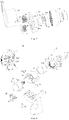
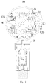
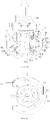
- Figs. 1 to 23 The corresponding relations between the reference numerals and the component names in Figs. 1 to 23 are: 100 household appliance, 10 air supply apparatus, 1 first fixed seat, 2 second fixed seat, 3 rotation driving mechanism, 31 fixed bracket, 311 body portion, 312 mounting groove, 313 mounting post, 314 first through hole, 315 second through hole, 16 positioning groove, 17 first mounting portion, 18 first positioning portion, 19 reinforcing structure, 32 rotary bracket, 321 second transmission member, 322 through-hole, 323 annular boss, 324 damping mechanism connection structure, 325 first routing channel, 326 stopper boss, 22 fitting groove, 23 third through hole, 4 driving assembly, 41 driving member, 42 first transmission member, 43 second mounting portion, 44 second positioning portion, 5 support bearing, 51 bearing inner ring stop, 52 bearing outer ring stop, 6 snap spring, 7 friction plate, 8 damper, 9 Hall assembly, 91 Hall plate, 92 magnet, 93 damping mechanism, 94 second routing channel, 20 head, 112 first damping frame, and 114 second damping frame
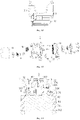
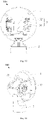
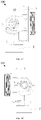
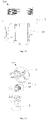
- a rotation driving mechanism 3, an air supply apparatus 10, and a household appliance 100 for an air supply apparatus are described below with reference to Figs. 1 to 23 .
- the rotation driving mechanism 3 is connected to a rotary component of the air supply apparatus, and the rotation driving mechanism 3 is used for driving the rotary component to rotate.
- the rotation driving mechanism 3 includes: a fixed bracket 31, a rotary bracket 32, and a driving member 41.
- the driving member 41 may be set to be a driving motor, and the driving motor may be a synchronous motor or a stepping motor.
- the fixed bracket 31 is fixedly arranged on a support structure of the air supply apparatus, the rotary bracket 32 being sleeved on the fixed bracket 31.
- the rotary bracket 32 is sleeved on the outer side of the fixed bracket 31, and the rotary bracket 32 is rotatable with respect to the fixed bracket 31; the rotary bracket 32 is connected to the rotary component of the air supply apparatus; the rotary bracket 32 can rotate with the rotary component; the driving member 41 is arranged on the fixed bracket 31; the driving member 41 is used for driving the rotary bracket 32 to rotate with respect to the fixed bracket 31.
- the rotation driving mechanism 3 drives the rotary component of the air supply apparatus to rotate
- the driving member 41 drives the rotary bracket 32 to make a predetermined trajectory rotation with respect to the fixed bracket 31, and the rotary bracket 32 can move together with the rotary component of the air supply apparatus during the rotation, thereby achieving the working purpose of the rotation of the rotary component of the air supply apparatus.
- the size of the rotation driving mechanism 3 of the present invention is smaller than a crank and rocker mechanism of the prior art, and such an arrangement can reduce the size of the rotation driving mechanism 3.
- the air supply apparatus can be made to look more compact, so that the air supply apparatus can be made more pleasing to the eye.
- the rotation angle range of the rotary bracket 32 with respect to the fixed bracket 31 is 0° to 360°, namely, the rotary bracket 32 moves with respect to the fixed bracket 31 over the entire circumference.
- the rotation of rotary bracket 32 has no limiting position so that the rotation angle of the rotary bracket 32 with respect to the fixed bracket 31 can be made unlimited, and the shaking angle of the rotary component of the air supply apparatus can be enlarged such that the air supply range of the air supply apparatus can be enlarged.
- the size of the rotation driving mechanism 3 can be reduced as compared with the prior art.
- the air supply apparatus can be made more pleasing to the eye after the rotation driving mechanism 3 is mounted on the air supply apparatus, and the rotation angle of the rotary bracket 32 with respect to the fixed bracket 31 is not limited, and the shaking angle of the rotary component of the air supply apparatus can be enlarged.
- the rotation driving mechanism 3 may further include: a first transmission member 42, wherein the rotary bracket 32 is provided with a second transmission member 321 drivingly coordinating with the first transmission member 42, the first transmission member 42 being connected to the driving shaft of the driving member 41.
- the driving member 41 drives the driving shaft to rotate, and the driving shaft carries the first transmission member 42 to rotate.
- the first transmission member 42 transmits power to the second transmission member 321, and then the second transmission member 321 drives the rotary bracket 32 to rotate so as to achieve the working effect of driving the rotary bracket 32 to rotate with respect to the fixed bracket 31.
- the first transmission member 42 may be provided as a gear
- the second transmission member 321 may be provided as a rack.
- the gear is engaged with the rack, and the power of the driving member 41 can be transmitted to the rotary bracket 32 via the transmission between the gear and the rack so that the rotary bracket 32 rotates.
- the power can be smoothly transmitted to the rotary bracket 32 so as to smoothly rotate the rotary bracket 32, thereby making the arrangement of the first transmission member 42 and the second transmission member 321 more reasonable and making the rotary component of air supply apparatus rotates more smoothly.
- the fixed bracket 31 may include: a body portion 311, wherein the body portion 311 defines a mounting groove 312, the side wall of the mounting groove 312 has a first through hole 314, the first through hole 314 communicates with the mounting groove 312, the first transmission member 42 is located in the mounting groove 312, and the first transmission member 42 drivingly coordinates with the second transmission member 321 via the first through hole 314.
- a part of the structure of the first transmission member 42 is located in the mounting groove 312, and another part of the structure of the first transmission member 42 is engaged with the second transmission member 321 after extending out of the first through hole 314 so that the first transmission member 42 and the second transmission member 321 drivingly mate.
- the power transmission from the driving member 41 to the rotary bracket 32 can be ensured, and the size of the rotation driving mechanism 3 can be further reduced compared with the prior art.
- the second transmission member 321 may be arranged at the inner wall surface of the rotary bracket 32 opposite to the fixed bracket 31. Such arrangement facilitates the driving coordinating between the second transmission member 321 and the first transmission member 42 so that the size of the rotation driving mechanism 3 can be better reduced. Therefore, the arrangement position of the second transmission member 321 may be more reasonable.
- the rotation driving mechanism 3 may further comprise: a damper 8, wherein the damper 8 can be a damper, the side wall of the mounting groove 312 can have a second through hole 315, the damper 8 can be provided on the fixed bracket 31 and located in the mounting groove 312, and the damper 8 drivingly coordinates with the second transmission member 321 via the second through hole 315.
- damper 8 A part of the structure of the damper 8 is located in the mounting groove 312, and another part of the structure of the damper 8 extends out of the second through hole 315 and then engages with the second transmission member 321; the damper 8 has a buffering function; during the rotation of the rotary bracket 32, the rotary bracket 32 can be kept rotating stably by the damper 8 coordinating with the second transmission member 321; when the rotary bracket 32 is forced to rotate driven by an external force, the rotation driving mechanism 3 can be prevented from being damaged. It needs to be noted that dampers 8 with different specification structures can be used according to actual conditions.
- multiple dampers 8 and multiple second through holes 315 may be provided, and multiple dampers 8 and multiple second through holes 315 are provided in a one-to-one correspondence so that stable rotation of the rotary bracket 32 can be better kept, and the damage to the rotation driving mechanism 3 can be better prevented when the rotary bracket 32 is forced to rotate by being driven by an external force.
- the rotation driving mechanism 3 may further comprise: a support bearing 5, wherein the support bearing 5 is supported between the fixed bracket 31 and the rotary bracket 32, so that the fixed bracket 31 and the rotary bracket 32 can be better assembled together, and when the rotary bracket 32 rotates, it can ensure that the rotary bracket 32 rotates smoothly with respect to the fixed bracket 31; the support bearing 5 has a supporting effect on the rotary bracket 32, and can avoid the rotary bracket 32 from shaking.
- the outer wall surface of the bottom wall of the mounting groove 312 can be provided with a mounting post 313, the inner ring of the support bearing 5 can be sleeved on the outer surface of the mounting post 313, the inner ring of the support bearing 5 is connected to the mounting post 313, and the outer ring of the support bearing 5 is connected to the rotary bracket 32.
- Such arrangement can ensure that the rotary bracket 32 and the fixed bracket 31 can rotate with respect to each other, and can ensure the working performance of the rotation driving mechanism 3.
- the inner wall surface of the bottom wall of the mounting groove 312 may be provided with a reinforcing structure 19.
- the reinforcing structure 19 is integrally formed with the mounting post 313 such that the structural strength of the fixed bracket 31 may be improved and the deformation of the fixed bracket 31 may be avoided.
- the rotation driving mechanism 3 may further include: a friction plate 7, wherein the rotary bracket 32 can define a fitting groove 22, the support bearing 5 is located in the fitting groove 22, and the bottom wall of the fitting groove 22 can be provided with a third through hole 23; the free end of the mounting post 313 extends out of the third through hole 23, the friction plate 7 can be sleeved on the outer surface of the mounting post 313, and the friction plate 7 abuts against the outer end of the third through hole 23; the friction plate 7 has wear-resistant and easy-to-wear properties; by providing the friction plate 7, the gap between the rotary bracket 32 and the fixed bracket 31 can be controlled, so that the structure of the rotation driving mechanism 3 can be made more stable, and the friction plate 7 can provide a lubricating effect when the rotary bracket 32 rotates. Therefore, the rotation of the rotary bracket 32 can be facilitated, and further, the rotational noise of the rotary bracket 32 can be reduced.
- a friction plate 7 wherein the rotary bracket 32 can define a fitting groove 22, the support bearing 5
- the rotation driving mechanism 3 may further include: a snap spring 6, wherein the circumferential wall surface of the mounting post 313 can be provided with a positioning groove 16, the positioning groove 16 is arranged along the circumferential direction of the mounting post 313, and the snap spring 6 is provided in the positioning groove 16; the snap spring 6 abuts against the end surface of the friction plate 7 away from the third through hole 23, as shown in Fig.
- the edge of the open end of the mounting groove 312 may be provided with a first mounting portion 17, and the driving member 41 may be provided with a second mounting portion 43 connected to the first mounting portion 17, wherein the driving member 41 can be fixed on the fixed bracket 31 by coordinating the first mounting portion 17 and the second mounting portion 43 for connection so that the driving member 41 can be prevented from falling off the fixed bracket 31.
- the first mounting portion 17 may be provided with a first positioning portion 18, and the second mounting portion 43 may be provided with a second positioning portion 44 connected to the first positioning portion 18.
- the first positioning portion 18 can be provided as a positioning post, and the second positioning portion 44 can be provided as a positioning hole; when mounting the driving member 41 and the fixed bracket 31, the positioning post is firstly inserted into the positioning hole so that the relative positions of the driving member 41 and the fixed bracket 31 can be positioned; then, the driving member 41 and the fixed bracket 31 are assembled together by using a bolt so that the assembly of the driving member 41 and the fixed bracket 31 is facilitated, and the assembly efficiency of the rotation driving mechanism 3 can be improved.
- the rotation driving mechanism 3 may further comprise: a hall assembly (not shown in the figure), wherein the Hall assembly may comprise a Hall plate and a magnet, either the Hall plate or magnet is provided on the fixed bracket 31, and the other of the Hall plate and magnet is provided on the rotary bracket 32.
- the Hall plate and the magnet can work coordinatingly to achieve the purpose of controlling the rotary bracket 32 to rotate by a specified angle so that the rotation driving mechanism 3 can meet different working requirements of a user.
- the fixed bracket 31 may be provided with a first limiting structure (not shown in the figure), and the rotary bracket 32 may be provided with a second limiting structure (not shown in the figure) coordinating with the first limiting structure in limiting.
- the first limiting structure and the second limiting structure coordinate to work so that the working purpose of controlling the rotary bracket 32 to rotate the specified angle can be achieved. Therefore, the rotation driving mechanism 3 can be made to meet the different working requirements of a user.
- the central axis of the driving member 41, the central axis of the fixed bracket 31, and the central axis of the rotary bracket 32 are arranged to coincide. Such arrangement can further reduce the size of the rotation driving mechanism 3 in a direction perpendicular to the central axis, and can make the structure of the rotation driving mechanism 3 more compact.
- a rotation driving mechanism 3 according to a second specific embodiment of the present invention is shown.
- the central axis of the fixed bracket 31 and the central axis of the rotary bracket 32 coincide, and the central axis of the driving member 41 and the central axis of the fixed bracket 31 do not coincide.
- the rotation driving mechanism 3 is arranged on the air supply apparatus so that the rotation driving mechanism 3 can reduce the size of the rotation driving mechanism 3; after the rotation driving mechanism 3 is mounted on the air supply apparatus, the air supply apparatus can be more pleasing to the eye, and the rotary bracket 32 has no limitation with respect to the rotation angle of the fixed bracket 31, and the shaking angle of the rotary component of the air supply apparatus can be enlarged.
- the air supply apparatus 10 may be an appliance having a pitch function, such as a fan, a heater NPS-Q, etc.
- a fan is taken as an example for illustrating the air supply apparatus 10.
- the air supply apparatus 10 comprises: a first fixed seat 1, a second fixed seat 2, and a rotation driving mechanism 3.
- the second fixed seat 2 is connected to the head 20 of the air supply apparatus 10, namely, the second fixed seat 2 is connected to the head 20 of the fan.
- the first fixed seat 1 is used for supporting the rotation driving mechanism 3;
- the rotation driving mechanism 3 has a fixed bracket 31 and a rotary bracket 32, wherein the fixed bracket 31 is fixedly connected to the first fixed seat 1, the rotary bracket 32 is fixedly connected to the second fixed seat 2, the rotary bracket 32 is sleeved over the outer side of the fixed bracket 31, and the rotation driving mechanism 3 further has a driving assembly 4, the driving assembly 4 being adapted to drive the rotary bracket 32 to rotate around the pitch axis.
- the pitch axis can be arranged in parallel with the horizontal plane.
- the driving assembly 4 drives the rotary bracket 32 to rotate around the pitch axis
- the second fixed seat 2 will rotate around the pitch axis together with the rotary bracket 32 so that the head 20 of the air supply apparatus 10 can rotate in an up-and-down direction. At that, the pitching action of the head 20 of the fan can be achieved.
- the driving assembly 4 drives the rotary bracket 32 to rotate around the pitch axis.
- the rotary bracket 32 rotates
- the second fixed seat 2 rotates around the pitch axis.
- the head 20 rotates together in the up-and-down direction, so as to achieve the working purpose of the pitching action of the head 20 of the air supply apparatus 10.
- the size of rotation driving mechanism 3 can be reduced compared with the prior art.
- the air supply apparatus 10 After the air supply apparatus 10 is assembled, the air supply apparatus 10 can be made more pleasing to the eye, thereby improving the market competitiveness of the air supply apparatus 10.
- the driving assembly 4 may include: a driving member 41 and a first transmission member 42, the first transmission member 42 being connected to the driving member 41.
- the driving member 41 can be provided as a driving motor
- the first transmission member 42 is connected to the output shaft of the driving motor
- the rotary bracket 32 can be provided with a second transmission member 321 engaging with the first transmission member 42 for transmission.
- the driving motor can provide power for the rotation of the rotary bracket 32; when the driving member 41 works, the driving member 41 drives the output shaft to rotate, and the output shaft rotates with the first transmission member 42; at the same time, the first transmission member 42 transmits power to the second transmission member 321; and then the second transmission member 321 drives the rotary bracket 32 to rotate around the pitch axis, so as to achieve the working effect of driving the second fixed seat 2 to rotate with respect to the first fixed seat 1.
- the first transmission member 42 may be provided as a gear
- the second transmission member 321 may be provided as a rack.
- the gear and the rack are engaged together.
- the power of the driving member 41 can be transmitted to the rotary bracket 32 through gear and rack transmission so that the rotary bracket 32 rotates.
- the power can be smoothly transmitted to the rotary bracket 32 so that the rotary bracket 32 smoothly rotates around the pitch axis, and therefore, the arrangement of the first transmission member 42 and the second transmission member 321 can be more reasonable, and the head 20 of the air supply apparatus 10 can also rotate more smoothly.
- the rotation driving mechanism 3 may further include: a support bearing 5, wherein the fixed bracket 31 may comprise a body portion 311, the body portion 311 may define a mounting groove 312, and the outer wall surface of the bottom wall of the mounting groove 312 may be provided with a mounting post 313; the inner ring of the support bearing 5 is sleeved on the outer side of the mounting post 313, and the outer ring of the support bearing 5 is connected to the rotary bracket 32 so that the fixed bracket 31 and the rotary bracket 32 can be better assembled together.
- a support bearing 5 wherein the fixed bracket 31 may comprise a body portion 311, the body portion 311 may define a mounting groove 312, and the outer wall surface of the bottom wall of the mounting groove 312 may be provided with a mounting post 313; the inner ring of the support bearing 5 is sleeved on the outer side of the mounting post 313, and the outer ring of the support bearing 5 is connected to the rotary bracket 32 so that the fixed bracket 31 and the rotary bracket 32 can be better assembled together.
- the rotary bracket 32 may define a through-hole 322, the through-hole 322 penetrates through the rotary bracket 32 in the thickness direction of the rotary bracket 32, and the through-hole 322 is sleeved on the outer side of the fixed bracket 31 and the support bearing 5, so that the working purpose of the rotary bracket 32 sleeved on the fixed bracket 31 can be achieved.
- the air supply apparatus 10 can be assembled smoothly, and the connection of the rotary bracket 32 to the outer ring of the support bearing 5 can also be facilitated.
- the inner wall surface of the through-hole 322 may be provided with an annular boss 323, and the inner wall surface of the annular boss 323 may be provided with a second transmission member 321, i. e., the inner wall surface of the annular boss 323 may be provided with a rack, and the rack may be arranged to extend along the thickness direction of the rotary bracket 32.
- a second transmission member 321 i. e., the inner wall surface of the annular boss 323 may be provided with a rack, and the rack may be arranged to extend along the thickness direction of the rotary bracket 32.
- the inner wall surface of the through-hole 322 is provided with a stopper boss 326, the stopper boss 326 is located between the annular boss 323 and the support bearing 5, and the stopper boss 326 abuts the support bearing 5.
- the stopper boss 326 abuts the support bearing 5, and the support bearing 5 can limit the stopper boss 326 and prevent the rotary bracket 32 from separating from the fixed bracket 31. Therefore, the assembly reliability of the rotation driving mechanism 3 can be ensured, and therefore, the working reliability of the rotation driving mechanism 3 can be ensured.
- the rotation driving mechanism 3 may further include: a snap spring 6, wherein the snap spring 6 is sleeved on the outer side of the mounting post 313, and the snap spring 6 is located at the end of the support bearing 5 away from the fixed bracket 31.
- the circumferential wall surface of the mounting post 313 may be provided with a positioning groove, the positioning groove is arranged along the circumferential direction of the mounting post 313, the snap spring 6 is provided in the positioning groove, and the snap spring 6 abuts one end of the support bearing 5 away from the fixed bracket 31.
- the rotation driving mechanism 3 may further include: a bearing inner ring stop 51, wherein the bearing inner ring stop 51 may be provided on the fixed bracket 31, and the bearing inner ring stop 51 is located at one end of the support bearing 5 away from the fixed bracket 31.
- the bearing inner ring stop 51 can be connected to the fixed bracket 31 via a bolt. After the mounting of the rotation driving mechanism 3 is completed, the bearing inner ring stop 51 abuts one end of the support bearing 5 away from the fixed bracket 31 so that the support bearing 5 can be reliably mounted on the fixed bracket 31, and the support bearing 5 can be prevented from falling off the mounting post 313.
- the rotation driving mechanism 3 may further include: a bearing outer ring stop 52, wherein bearing outer ring stop 52 may be provided on the rotary bracket 32 and the bearing outer ring stop 52 is located at one end of the support bearing 5 away from the fixed bracket 31.
- the bearing outer ring stop 52 can be connected to the rotary bracket 32 via a bolt. After the rotation driving mechanism 3 is mounted, the bearing outer ring stop 52 abuts one end of the support bearing 5 away from the fixed bracket 31, which can further prevent the support bearing 5 from falling off the mounting post 313 so that the support bearing 5 can be reliably mounted on the fixed bracket 31. Further, the support bearing 5 can be reliably supported between the fixed bracket 31 and the rotary bracket 32.
- the rotation driving mechanism 3 may further comprise: an annular friction plate 7, the friction plate 7 being made of wear-resistant and easy-to-wear materials.
- the body portion 311 is sleeved on the outer side of the friction plate 7, and the friction plate 7 is sleeved on the outer side of the rotary bracket 32.
- the friction plate 7 can provide a lubricating effect when the rotary bracket 32 rotates, thereby facilitating the rotation of the rotary bracket 32 and reducing the rotational noise of the rotary bracket 32.
- the rotation driving mechanism 3 of the first embodiment of the present invention differs from the rotation driving mechanism 3 of the second embodiment of the present invention in that the friction plate 7 is not provided in the rotation driving mechanism 3 of the second embodiment.
- the rotation driving mechanism 3 of the first embodiment limits the support bearing 5 via the snap spring 6, and the rotation driving mechanism 3 of the second embodiment limits the support bearing 5 via the bearing outer ring stop 52 and the bearing inner ring stop 51.
- the side wall of the mounting groove 312 may have a first through hole 314, the first through hole 314 being in communication with the mounting groove 312.
- Both the driving member 41 and the first transmission member 42 may be located in the mounting groove 312, and part of the structure of the first transmission member 42 passes through the first through hole 314 and then drivingly coordinates with the second transmission member 321.
- a part of the structure of the first transmission member 42 is located in the mounting groove 312, and another part of the structure of the first transmission member 42 is engaged with the second transmission member 321 after extending out of the first through hole 314 so that the first transmission member 42 and the second transmission member 321 drivingly engage to coordinate.
- the power transmission from the driving member 41 to the rotary bracket 32 can be ensured, and the size of the rotation driving mechanism 3 can be further reduced compared with the prior art.
- the gear and the rack have high transmission accuracy and can precisely control the pitch angle of a head 20 of a fan.
- the rotation driving mechanism 3 may further include: a damper 8, wherein the side wall of the mounting groove 312 may have a second through hole 315, and the damper 8 may be arranged in the mounting groove 312, and a part of the structure of the damper 8 passes through the second through hole 315 and then drivingly coordinates with the second transmission member 321.
- damper 8 A part of the structure of the damper 8 is located in the mounting groove 312, and another part of the structure of the damper 8 extends out of the second through hole 315 and then engages with the second transmission member 321; the damper 8 has a buffering function; during the rotation of the rotary bracket 32, the rotary bracket 32 can be kept rotating stably by the damper 8 drivingly engaging with the second transmission member 321; when the rotary bracket 32 is forced to rotate driven by an external force, the rotation driving mechanism 3 can be prevented from being damaged. It needs to be noted that dampers 8 with different specification structures can be used according to actual conditions.
- the rotation driving mechanism 3 further includes: a Hall assembly 9, wherein the Hall assembly 9 may comprise a Hall plate 91 and a magnet 92, either the Hall plate 91 or the magnet 92 being provided at the fixed bracket 31, and the other of the Hall plate 91 and the magnet 92 being provided on the rotary bracket 32.
- the Hall assembly 9 may comprise a Hall plate 91 and a magnet 92, either the Hall plate 91 or the magnet 92 being provided at the fixed bracket 31, and the other of the Hall plate 91 and the magnet 92 being provided on the rotary bracket 32.
- the working purpose of controlling the rotary bracket 32 to rotate around the pitch axis by a specified angle can be achieved, so that the pitch angle of the rotation of the head 20 of the fan can be controlled, and then the air supply apparatus 10 can meet the requirements of different air supply angles of a user.
- the depression angle of the rotary bracket 32 may be set to A, meeting the relational expression: -10° ⁇ A ⁇ 0°, and the elevation angle of rotary bracket 32 may be set as B, meeting the relational expression: 0° ⁇ B ⁇ 90°.
- Such setting can enable head 20 of a fan to have a pitch angle of 100° in the up and down direction, and can enable head 20 to have sufficient air supply area in the up and down direction so that the air supply apparatus 10 can meet the air supply requirement of a user.
- the air supply apparatus 10 may further include: a damping mechanism 93, wherein the damping mechanism 93 may be arranged on the fixed bracket 31, and the damping mechanism 93 is pivotably connected to the rotary bracket 32, i. e. the damping mechanism 93 is connected to the rotary bracket 32, and the rotary bracket 32 is pivotable with respect to the damping mechanism 93.
- the damping mechanism 93 is made of a wear-resistant material, and damping oil is added in a groove of the damping mechanism 93; after the assembly of the air supply apparatus 10 is completed, when the rotary bracket 32 rotates around a pivot axis, the damping mechanism 93 can play a damping effect, and can better keep the stable rotation of the rotary bracket 32; when the rotary bracket 32 is forced to rotate under the driving of an external force, the rotation driving mechanism 3 can be better prevented from being damaged, and at the same time, the damping mechanism 93 can play a supporting role on the rotary bracket 32, and can prevent the rotary bracket 32 from shaking. It needs to be noted that the damping mechanism 93 can use a damper with different specification structures according to actual conditions.
- the rotary bracket 32 may have a damping mechanism connection structure 324.
- the damping mechanism connection structure 324 is sleeved on the damping mechanism 93 such that the overall structure of the second fixed seat 2 and rotation driving mechanism 3 is more compact.
- the damping mechanism connection structure 324 may have a first routing channel 325, and the damping mechanism 93 may have a second routing channel 94 in communication with the first routing channel 325.
- a wiring harness connecting the driving motor may pass through the first routing channel 325 and the second routing channel 94 and then connect with the driving motor so that the wiring of the air supply apparatus 10 may be more convenient. Further, the structural arrangement of the damping mechanism connection structure 324 and the damping mechanism 93 may be reasonable.
- a household appliance 100 proposed according to some embodiments of the present invention will be described below with reference to Figs. 15 to 23 .
- the present invention proposes a household appliance 100, including: a first fixed seat 1, a second fixed seat 2, and a rotation driving mechanism 3.
- the rotation driving mechanism 3 comprises a fixed bracket 31 and a rotary bracket 32.
- the fixed bracket 31 is connected to the second fixed seat 2, and the rotary bracket 32 is connected to the first fixed seat 1; among other things, the rotary bracket 32 is adapted to rotate around the fixed bracket 31 to link the first fixed seat 1 to rotate around the second fixed seat 2.
- the household appliance 100 provided by the present invention comprises a second fixed seat 2, a first fixed seat 1, and a rotation driving mechanism 3.
- the second fixed seat 2 and the first fixed seat 1 are connected via the rotation driving mechanism 3, and the rotation driving mechanism 3 can drive the first fixed seat 1 to rotate so as to realize the automatic adjustment of the pitch angle of the first fixed seat 1.
- the rotation driving mechanism 3 comprises a fixed bracket 31 and a rotary bracket 32.
- the fixed bracket 31 is connected to the second fixed seat 2, the rotary bracket 32 is connected to the first fixed seat 1, and the rotary bracket 32 is adapted to rotate around the fixed bracket 31. Therefore, the first fixed seat 1 can be driven to rotate around the fixed bracket 31, that is, the first fixed seat 1 can be driven to rotate around the second fixed seat 2, so as to realize the rotation of the first fixed seat 1 and the components connected thereto in the household appliance 100.
- a rotation driving mechanism 3 is provided between the second fixed seat 2 and the first fixed seat 1, and the first fixed seat 1 is driven to rotate by the rotation driving mechanism 3, so as to achieve the automatic adjustment of the pitch angle of the first fixed seat 1 and the components thereon.
- the second fixed seat 2 and the first fixed seat 1 are connected by means of the rotation driving mechanism 3.
- the rotary bracket 32 can rotate around the circumference of the fixed bracket 31, and the structure is simple and reliable, thereby making the household appliance 100 more reliable.
- the axis around which the rotary bracket 32 rotates around the fixed bracket 31 is perpendicular to the length direction of the second fixed seat 2.
- the first fixed seat 1 can be enabled to rotate to the upward side of the household appliance 100, or to the downward side of the household appliance 100, that is, the adjustment of the pitch angle of the first fixed seat 1 is realized.
- the first fixed seat 1 has at least one supporting point.
- the portion of the rotary bracket 32 connected to the first fixed seat 1 supports the first fixed seat 1 such that the first fixed seat 1 rotates with the rotation of the rotary bracket 32 by taking the supporting point as the center, that is, the first fixed seat 1 can be connected to the second fixed seat 2 through a single arm.
- the first fixed seat 1 further comprises a support portion, wherein the support portion is rotatably connected to the second fixed seat 2, and the support portion coincides with the axis about which the second fixed seat 2 rotates and the axis about which the rotary bracket 32 rotates around the fixed bracket 31; that is to say, the first fixed seat 1 can also be connected to the second fixed seat 2 via a two-arm form.
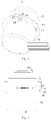
- Fig. 16 the second fixed seat 2 and the first fixed seat 1 are connected to the rotary bracket 32 via the fixed bracket 31, and the rotary bracket 32 rotates around the fixed bracket 31 so that the first fixed seat 1 rotates around the second fixed seat 2, thereby achieving the automatic adjustment of the pitch angle of the first fixed seat 1.
- Figs. 17 and 18 are a left side view and a top view of the household appliance 100.
- Fig. 19 is a top view of the household appliance 100. It can be seen from Figs. 17 to 19 that the structure is simple and the occupied size is smaller.
- the household appliance 100 further includes: a first damping frame 112 connected to the first fixed seat 1, and a second damping frame 114 connected to the fixed bracket 31, wherein the second damping frame 114 is sleeved on the first damping frame 112, and the first damping frame 112 is adapted to rotate around the second damping frame 114.
- the household appliance 100 further comprises a first damping frame 112 and a second damping frame 114.
- the first damping frame 112 is connected to the first fixed seat 1, and the second damping frame is connected to the fixed bracket 31. Therefore, the first fixed seat 1 can be supported by the first damping frame 112 and the second damping frame 114, and the reliability of the mounting of the first fixed seat 1 is improved.
- the second damping frame 114 is sleeved on the first damping frame 112, and the first damping frame 112 can rotate around the second damping frame 114 so that the first fixed seat 1 can rotate around the second fixed seat 2 under the driving of the rotary bracket 32.
- the coordination of the first damping frame 112 and the second damping frame 114 serves as a support for the first fixed seat 1, that is, the first fixed seat 1 can rotate by taking the first damping frame 112 and the second damping frame 114 as supporting points.
- the first fixed seat 1 has two supporting points.
- One supporting point is composed of a portion of the first fixed seat 1 connected to the rotary bracket 32, and the other supporting point is composed of a portion of the first fixed seat 1 connected to the first damping frame 112.
- first damping frame 112 and the second damping frame 114 are located at one end of the fixed bracket 31, and the portion of the rotary bracket 32 connected to the first fixed seat 1 is located at the other end of the fixed bracket 31, namely, in the direction of the axis around which the rotary bracket 32 rotates.
- the two supporting points of the first fixed seat 1 are located at both ends of the rotation driving mechanism 3, thereby improving the supporting effect on the first fixed seat 1 and ensuring the reliability of the household appliance 100.
- damping fluid is provided between the first damping frame 112 and the second damping frame 114.
- damping fluid is provided between the first damping frame 112 and the second damping frame 114 to provide a damping force as the first damping frame 112 rotates around the second damping frame 114, ensuring the stability of the household appliance 100.
- the second damping frame 114 is sleeved on the first damping frame 112, i. e. the inner side wall of the second damping frame 114 is sleeved outside the outer side wall of the first damping frame 112.
- Damping fluid is provided between the first damping frame 112 and the second damping frame 114, i. e. the damping fluid is provided between the outer side wall of the first damping frame 112 and the inner side wall of the second damping frame 114 so that the damping fluid provides a damping force when the first damping frame 112 and the second damping frame 114 perform a rotational movement.
- damping fluid is a liquid capable of generating a damping force, and capable of damping the kinetic energy of a moving machine by virtue of the viscous drag of the liquid medium.
- the damping fluid includes a viscous liquid, such as oily liquid and the like, depending on the specific usage condition.
- the rotation angle of the first fixed seat 1 is greater than 0° and less than or equal to 200°.
- the rotation angle of the first fixed seat 1 is greater than or equal to 0° and less than or equal to 200°.
- the elevation angle of the rotation of the first fixed seat 1 is greater than or equal to 0° and less than or equal to 90°
- the depression angle of the first fixed seat 1 is greater than or equal to 0° and less than or equal to 10°, wherein the elevation angle of the first fixed seat 1 is the angle of the rotation of the first fixed seat 1 from a horizontal position to an upward side, and the depression angle of the first fixed seat 1 is the angle of the rotation of the first fixed seat 1 from a horizontal position to a downward side.
- the household appliance 100 further comprises: a Hall plate 91 arranged on the second fixed seat 2, wherein the first fixed seat 1 is further provided with a magnetic member, and the Hall plate 91 is connected to the magnetic member.
- the Hall plate 91 is provided on the second fixed seat 2, and a magnetic member is provided on the first fixed seat 1.
- the movement of the first fixed seat 1 at any angle can be realized through the coordination between the Hall plate 91 and the magnetic member, namely, the coordination between the Hall plate 91 and the magnetic member can enable the first fixed seat 1 to rotate any specified angle around the second fixed seat 2.
- the first fixed seat 1 is required to rotate any specified angle around the second fixed seat 2 by 30° or 60° or 90°, etc. from an initial position.
- the Hall plate 91 is an component with the Hall effect.
- the second fixed seat 2 is provided with a hollow portion, the hollow portion is provided corresponding to the first damping frame 112, the household appliance 100 further comprises a connecting wire, and the connecting wire is adapted to be connected to the second fixed seat 2 by passing through the hollow portion from the first fixed seat 1.
- the second fixed seat 2 is provided with a hollow portion
- the household appliance 100 further comprises a connecting wire.
- the connecting wire can pass through the hollow portion, namely, the connecting wire can pass through the hollow portion to connect to the first fixed seat 1 and other components thereon so that the wiring of the household appliance 100 is more reliable.
- the rotation driving mechanism 3 further includes: a driving member 41, wherein the driving member 41 and the fixed bracket 31 are connected; and a first transmission member 42, wherein the first transmission member 42 is connected to the driving member 41 and the rotary bracket 32, respectively, the driving member 41 being adapted to drive the first transmission member 42 to rotate to link the rotary bracket 32 to rotate.
- the driving member 41 drives the first transmission member 42 to rotate so that the first transmission member 42 drives the rotary bracket 32 to rotate; it could be understood that the first transmission member 42 rotates to link the rotary bracket 32 to rotate, namely, the driving member 41 drives the first transmission member 42 to rotate; since the first transmission member 42 is connected to the rotary bracket 32, the first transmission member 42 can drive the rotary bracket 32 to move, namely, the first transmission member 42 rotation links the rotary bracket 32 to rotate.
- the driving member 41 comprises a motor
- the motor may be a synchronous motor or a stepping motor.
- the fixed bracket 31 includes: a body portion, wherein the body portion is connected with the driving member 41 and the second fixed seat 2; and a mounting post connected to the body portion, wherein the rotary bracket 32 is sleeved on the mounting post, and the rotary bracket 32 is adapted to rotate about the mounting post.
- the fixed bracket 31 comprises a body portion and a mounting post, and the driving member 41 is fixed on the body portion.
- the rotation driving mechanism 3 can also be fixed on other apparatuses via the body portion.
- the mounting post is provided on the body portion, and the rotary bracket 32 is sleeved on the mounting post, so as to realize the rotation of the rotary bracket 32 around the mounting post, and improve the reliability of the connection between the fixed bracket 31 and the rotary bracket 32.
- the rotary bracket 32 can rotate circumferentially around the fixed bracket 31. Sleeving the rotary bracket 32 on the mounting post of the fixed bracket 31 can reduce the size of the rotation driving mechanism 3.
- the body portion has a mounting groove 312, and the first transmission member 42 is provided on the mounting groove 312; a first through hole is provided on the wall surface of the mounting groove 312, the first through hole penetrates through the wall surface of the mounting groove 312, and the first transmission member 42 is connected to the rotary bracket 32 via the first through hole.
- the body portion has a mounting groove 312 with the first transmission member 42 provided within the mounting groove 312 to avoid the exposure of the first transmission member 42 to the outer side which affects the aesthetics of the rotation driving mechanism 3.
- the first transmission member 42 is provided in the mounting groove 312, and in order to realize the connection between the first transmission member 42 and the rotary bracket 32, a first through hole is provided in the wall surface of the mounting groove 312. This allows the first transmission member 42 to be connected to the rotary bracket 32 via the first through hole. It could be understood that the first through hole is a through hole penetrating through the wall surface of the mounting groove 312.
- the rotary bracket 32 is sleeved on the outer side of the mounting groove 312.
- the rotary bracket 32 includes: a connection portion, wherein the connection portion is sleeved on the mounting post, and one end of the connection portion away from the driving member 41 is connected to the first fixed seat 1; and a second transmission member 321 connected to the connection portion, wherein the first transmission member 42 is connected to the second transmission member 321, and the first transmission member 42 is adapted to drive the second transmission member 321 to rotate so as to link the connection portion to rotate.
- the rotary bracket 32 comprises a connection portion and a second transmission member 321 which are connected.
- the connection portion is sleeved on the mounting post, the second transmission member 321 is connected to the first transmission member 42, the driving member 41 drives the first transmission member 42 to rotate, and the first transmission member 42 drives the second transmission member 321 to rotate so that the connection portion connected to the second transmission member 321 rotates around the mounting post, i. e. the rotary bracket 32 rotates around the fixed bracket 31.
- connection portion and the second transmission member 321 are of an integrated structure.
- the first transmission member 42 is connected to the second transmission member 321 via the first through hole.
- the household appliance 100 further includes: a damper 8 connected to the body portion and provided on the mounting groove 312, the damper 8 including a third rotational member; wherein the second through hole is provided on the wall surface of the mounting groove 312, the second through hole penetrates through the wall surface of the mounting groove 312, and the third rotational member is connected to the second transmission member 321 via the second through hole.
- the household appliance 100 further includes a damper 8.
- the damper 8 is mounted on the body portion and housed in the mounting groove 312.
- the damper 8 comprises a third rotational member, and the third rotational member is connected to the second transmission member 321.
- the driving member 41 drives the first transmission member 42 to rotate
- the first transmission member 42 drives the second transmission member 321 to rotate
- the second transmission member 321 drives the third rotational member to rotate.
- a damping effect can be generated. That is to say, the kinetic energy of the rotation of the second transmission member 321 is consumed when the third rotational member rotates so that the kinetic energy of the rotation of the second transmission member 321 is attenuated, thereby forming a damping effect.
- the damper 8 ensures the stability of the rotation driving mechanism 3 during working, and at the same time, when the rotary bracket 32 is forcedly driven by an external force, the reliability of the rotation driving mechanism 3 can be ensured by the damping effect of the damper 8.
- the damper 8 further comprises a fixed seat and a limiting seat, wherein the limiting seat is provided on the fixed seat, the third rotational member is sleeved on the limiting seat, and the third rotational member and the limiting seat are adapted to accommodate damping fluid therebetween.
- the damper 8 comprises a fixed seat and a limiting seat.
- the fixed seat is used for mounting the damper 8 on the body portion
- the limiting seat is mounted on the fixed seat
- the third rotational member is sleeved on the limiting seat so as to mount the third rotational member on the fixed seat.
- the third rotational member can rotate around the limiting seat, and damping fluid is accommodated between the third rotational member and the limiting seat.
- the third rotational member rotates, it can drive the damping fluid between the third rotational member and the limiting seat to have a certain position change so as to generate energy consumption to generate resistance to the movement of the third rotational member and form a damping effect.
- damping fluid is a liquid capable of generating a damping force, and capable of damping the kinetic energy of a moving machine by virtue of the viscous drag of the liquid medium.
- the damping fluid includes a viscous liquid, such as oily liquid and the like, depending on the specific usage condition.
- the damper 8 may be another mechanism capable of forming a damping effect.
- each of the first transmission member 42, the second transmission member 321, and the third rotational member comprises a gear structure, and the first transmission member 42 and the second transmission member 321 are drivingly engaged through a gear structure, and the second transmission member 321 and the third rotational member are drivingly engaged through a gear structure.
- the first transmission member 42, the second transmission member 321, and the third rotational member all comprise a gear structure, and the first transmission member 42 and the second transmission member 321 are connected via the gear structure to realize a gear transmission and improve the reliability of the connection therebetween.
- the second transmission member 321 and the third rotational member are connected via the gear structure to realize a gear transmission and improve the reliability of the connection therebetween.
- the first transmission member 42 is an outer gear
- the second transmission member 321 is an inner gear
- the third rotational member is an outer gear. That is to say, the first transmission member 42 and the second transmission member 321 are both located in the second transmission member 321 and are connected to the third rotational member.
- the rotation of the first transmission member 42 can drive the rotation of the second transmission member 321, and the rotation of the third rotational member can have a damping effect on the rotation of the second transmission member 321.
- the driving member 41 comprises a rotor and an output shaft connected to the rotor, and the output shaft is connected to the first transmission member 42.
- the rotation axis of the rotor, the axis of the mounting post, and the axis around which the rotary bracket 32 rotates are arranged coaxially, or the rotation axis of the rotor and the axis of the mounting post do not coincide.
- the driving member 41 comprises an output shaft and a rotor, and the rotor rotates to drive the output shaft to rotate so that the first connecting member is driven to rotate via the output shaft.
- the axis rotated by the rotor, the axis of the mounting post, and the axis around which the rotary bracket 32 rotates are arranged coaxially so that the space occupied by the rotation driving mechanism 3 is reduced.
- the axis around which the rotor rotates and the axis of the mounting post do not coincide, i. e. the rotary bracket 32 moves eccentrically with respect to the driving member 41, so that the rotation driving mechanism 3 can be applied to different apparatuses depending on the actual situation.
- the household appliance 100 further includes: a support bearing 5 provided between the rotary bracket 32 and the mounting post; a limiting member along the direction of the axis about which the rotary bracket 32 rotates, the limiting member being located at one end of the rotary bracket 32 away from the driving member 41; a friction plate 7, along the direction of the axis about which the rotary bracket 32 rotates, the friction plate 7 being arranged between the rotary bracket 32 and the limiting member; and a limiting structure connected to the fixed bracket 31, the limiting structure being adapted to limit the rotation angle of the rotary bracket 32.
- the household appliance 100 further comprises a support bearing 5.
- the support bearing 5 is mounted inside the rotary bracket 32 and nested on the mounting post for connecting the rotary bracket 32 and the mounting post;
- the household appliance 100 further comprises a limiting member, wherein the limiting member is arranged on the rotary bracket 32 and is located at one end of the rotary bracket 32 away from the driving member 41; at the same time, the limiting member is clamped on the fixed bracket 31, thereby defining the support bearing 5 on the mounting post;
- the household appliance 100 further comprises a friction plate 7 mounted between the rotary bracket 32 and the limiting member and being made of a wear-resistant and easy-to-wear material, which can achieve the control of the gap between the rotary bracket 32 and the fixed bracket 31 and stabilize the rotation driving mechanism 3; at the same time, the friction plate 7 has a lubricating effect when the rotary bracket 32 rotates.
- the fixed bracket 31 is further provided with a limiting structure thereon, and the limiting structure can limit the rotary bracket 32 so as to fix the
- the limiting member is a snap spring.
- the friction plate 7 is a gasket made of a wear-resistant material, and further, the friction plate 7 is an elastic cushion.
- the household appliance 100 includes any one of the fan, air conditioner, and heater.
- the household appliance 100 comprises any one of the fan, air conditioner, or heater.
- the mounting portion is a support structure
- the rotational portion is a fan head
- the axis around which the rotary bracket 32 rotates in the rotation driving mechanism 3 is perpendicular to the length direction of the support structure so that the fan head can rotate up and down, namely, the adjustment of the pitch angle of the fan head is realized.
- a household air conditioner comprises a heater
- the heater comprises a head portion and a support portion.
- the head portion is provided with a heat-dissipating structure
- the head portion and the support portion are connected via the rotation driving mechanism 3, and the rotation axis of the rotary bracket 32 can be arranged perpendicular to the length direction of the support portion, thereby achieving the adjustment of the pitch angle of the heater.
- a household appliance 100 comprises a second fixed seat 2, a first fixed seat 1, and a rotation driving mechanism 3, the first fixed seat 1 being used for fixing an appliance such as a fan head of a fan.
- the first fixed seat 1 is used for supporting and mounting the rotation driving mechanism 3, and the second fixed seat 2, the first fixed seat 1 and the rotation driving mechanism 3 are supported via a fulcrum;
- the single-arm uses one fulcrum (the supporting point formed by the portion of the rotary bracket 32 connected with the first fixed seat 1)
- the two-arm uses two fulcrums (the supporting point formed by the portion of the rotary bracket 32 connected with the first fixed seat 1, and the supporting point formed by the first fixed seat 1, the first damping frame 112, and the second damping frame 114), and by centering on the fulcrum, first fixed seat 1 rotates with the operation of driving member 41 (motor) in rotation driving mechanism 3.
- the maximum depression angle is designed to be -10°, and the maximum elevation angle is designed to be 90°.
- the pitch angle (the other side) can be adjusted from -10° to 90°, and the pitch angle ranges from 0° to 200°. Further, if the Hall plate is added, any angle adjustment from -10° to 90° and 90° to -10° can be realized.
- a single-arm household appliance 100 capable of realizing an automatic pitch function including a second fixed seat 2, a first fixed seat 1, and a rotation driving mechanism 3, and the exploded view is as shown in Fig. 21 , specifically comprising:
- the working principle of the household appliance 100 proposed in the present invention is that: when the driving motor moves, power is transmitted to the rotary bracket 32 by driving the gear, and the rotary bracket 32, together with the first fixed seat 1, rotates by taking the fulcrum as the center.
- a two-arm household appliance 100 capable of realizing an automatic pitch function is shown, including a second fixed seat 2, a first fixed seat 1, and a rotation driving mechanism 3, and the exploded view is as shown in Fig. 9 , specifically comprising:
- the working principle of the household appliance 100 proposed in the present invention is that: when the driving motor moves, power is transmitted to the rotary bracket 32 by driving the gear, and the rotary bracket 32, together with the first fixed seat 1, rotates by taking the fulcrum as the center.
- the wiring at the joint is on the side of the first damping frame 112, and the middle of the left side of the movable joint of the first fixed seat 1 is hollowed out, which is convenient and reliable for wiring.
- This design uses the joint movement mode to add a friction plate 7 and a damper 8.
- the adjustment of the pitch angle of the appliance is skillfully realized through modular assemblies such as the rotation driving mechanism 3 so that the mechanism is stable and reliable, and the mounting is simple.
- the structure is optimized according to the product, which can be used for most apparatuses with automatic adjusting movement.
- the term “multiple” refers to two or more unless explicitly defined otherwise.
- Terms “mounted”, “connected”, “connect”, “fixed”, and the like are to be construed broadly.
- “connect” may be a fixed connection, a detachable connection, or an integral connection;
- “connected” can be either directly connected or indirectly connected through an intermediary.
- the specific meaning of the above-mentioned terms in the present invention can be understood according to specific situations.
Landscapes
- Engineering & Computer Science (AREA)
- Mechanical Engineering (AREA)
- General Engineering & Computer Science (AREA)
- Air-Flow Control Members (AREA)
- Structures Of Non-Positive Displacement Pumps (AREA)
- Transmission Devices (AREA)
- Loading And Unloading Of Fuel Tanks Or Ships (AREA)
Abstract
Description
- This application claims priority to
Chinese Patent Application No. 202020462542.1 filed with China National Intellectual Property Administration on April 02, 2020 Chinese Patent Application No. 202010254409.1 filed with China National Intellectual Property Administration on April 02, 2020 Chinese Patent Application No. 202010254425.0 filed with China National Intellectual Property Administration on April 02, 2020 - The present invention relates to the technical field of household appliances, and in particular to a rotation driving mechanism for an air supply apparatus, an air supply apparatus, and a household appliance.
- In the related art, the rotation driving mechanism of the existing air supply apparatus realizes the head-shaking function for an air supply apparatus through a crank and rocker mechanism. But the size of the rotation driving mechanism is large, which makes the air supply apparatus unsightly. The crank and rocker mechanism has a pole, greatly limiting the shaking angle.
- The present invention aims to solve at least one of the technical problems existing in the prior art or related art.
- To this end, in the first aspect, the present invention provides a rotation driving mechanism for an air supply apparatus. The size of the rotation driving mechanism of the air supply apparatus is small, and after a rotary driving mechanism is mounted on the air supply apparatus, the air supply apparatus can be more pleasing to the eye and the shaking angle of the rotary component of air supply apparatus can also be enlarged.
- A second aspect of the present invention proposes an air supply apparatus.
- A third aspect of the present invention proposes a household appliance.
- The rotation driving mechanism for an air supply apparatus according to the present invention comprises a fixed bracket; a rotary bracket, wherein the rotary bracket is sleeved on the fixed bracket and is rotatable with respect to the fixed bracket; and a driving member, wherein the driving member is provided on the fixed bracket, and the driving member drives the rotary bracket to rotate.
- According to the rotation driving mechanism for an air supply apparatus according to the present invention, compared with the prior art, by means of the coordination of the fixed bracket, the rotary bracket, and the driving member, the size of the rotation driving mechanism can be reduced; after the rotation driving mechanism is mounted on the air supply apparatus, the air supply apparatus can have a better appearance; moreover, the rotation angle of the rotary bracket with respect to the fixed bracket is not limited, and thus, the shaking angle of the rotary component of the air supply apparatus can be enlarged.
- In some embodiments of the present invention, the rotation driving mechanism for an air supply apparatus further comprises: a first transmission member, the rotary bracket being provided with a second transmission member drivingly coordinating with the first transmission member, and the first transmission member being connected to a driving shaft of the driving member.
- According to some embodiments of the present invention, the fixed bracket comprises a body portion, the body portion defines a mounting groove, a side wall of the mounting groove has a first through hole, the first transmission member is located in the mounting groove, and the first transmission member drivingly coordinates with the second transmission member via the first through hole.
- In some embodiments of the present invention, the second transmission member is provided on the inner wall surface of the rotary bracket opposite to the fixed bracket.
- In some embodiments of the present invention, the first transmission member is a gear and the second transmission member is a rack.
- In some embodiments of the present invention, the rotation driving mechanism for an air supply apparatus further comprises: a damper, wherein the side wall of the mounting groove has a second through hole, the damper is provided on the fixed bracket and is located in the mounting groove, and the damper drivingly coordinates with the second transmission member via the second through hole.
- In some embodiments of the present invention, the rotation driving mechanism for an air supply apparatus further comprises: a support bearing, the support bearing being supported between the fixed bracket and the rotary bracket.
- In some embodiments of the present invention, the outer wall surface of a bottom wall of the mounting groove is provided with a mounting post, an inner ring of the support bearing is sleeved on the mounting post, and an outer ring of the support bearing is connected to the rotary bracket.
- In some embodiments of the present invention, the rotation driving mechanism for an air supply apparatus further comprises: a friction plate, wherein the rotary bracket defines a fitting groove, the bottom wall of the fitting groove is provided with a third through hole, and the friction plate is sleeved on the mounting post and abuts against an outer end of the third through hole.
- In some embodiments of the present invention, the rotation driving mechanism for an air supply apparatus further comprises: a snap spring, wherein a circumferential wall surface of the mounting post is provided with a positioning groove, the snap spring is provided in the positioning groove, and the snap spring abuts an end surface of the friction plate away from the third through hole.
- In some embodiments of the present invention, a first mounting portion is provided on the edge of the open end of the mounting groove and the driving member is provided with a second mounting portion connected to the first mounting portion.
- In some embodiments of the present invention, the first mounting portion is provided with a first positioning portion and the second mounting portion is provided with a second positioning portion connected to the first positioning portion.
- In some embodiments of the present invention, the rotation driving mechanism for an air supply apparatus further comprises: a Hall assembly, wherein the Hall assembly comprises a Hall plate and a magnet, and either the Hall plate or the magnet is provided on the fixed bracket, and the other of the Hall plate and the magnet is provided on the rotary bracket.
- In some embodiments of the present invention, the fixed bracket is provided with a first limiting structure and the rotary bracket is provided with a second limiting structure coordinating with the first limiting structure in limiting.
- In some embodiments of the present invention, a central axis of the driving member, a central axis of the fixed bracket, and a central axis of the rotary bracket coincide.
- In some embodiments of the present invention, a central axis of the fixed bracket and a central axis of the rotary bracket coincide, and a central axis of the driving member and the central axis of the fixed bracket do not coincide.
- In some embodiments of the present invention, the damper is multiple, the second through hole is multiple, and the multiple dampers and the multiple second through holes are in a one-to-one correspondence.
- In some embodiments of the present invention, the driving member is a driving motor.
- The air supply apparatus according to the present invention comprises: a first fixed seat; a second fixed seat, the second fixed seat being connected to a head of the air supply apparatus; and a rotation driving mechanism, the rotation driving mechanism having a fixed bracket and a rotary bracket, the fixed bracket being fixedly connected to the first fixed seat, and the rotary bracket being fixedly connected to the second fixed seat; wherein the rotary bracket is sleeved on the fixed bracket, and the rotation driving mechanism further has a driving assembly, and the driving assembly drives the rotary bracket to rotate around a pitch axis.
- According to the air supply apparatus of the present invention, through the coordination of the first fixed seat, the second fixed seat, and the rotation driving mechanism, the size of the rotation driving mechanism can be reduced compared with the prior art. After the air supply apparatus is assembled, the air supply apparatus can be made more pleasing to the eye, thereby improving the market competitiveness of the air supply apparatus.
- In some embodiments of the present invention, the pitch axis is parallel to the horizontal plane.
- In some embodiments of the present invention, the driving assembly includes: a driving member and a first transmission member, wherein the first transmission member is connected to the driving member, and the rotary bracket is provided with a second transmission member drivingly engaging with the first transmission member.
- In some embodiments of the present invention, the rotation driving mechanism further comprises: a support bearing, wherein the fixed bracket comprises a body portion, the body portion defines a mounting groove, an outer wall surface of a bottom wall of the mounting groove is provided with a mounting post, an inner ring of the support bearing is sleeved on the mounting post, and an outer ring of the support bearing is connected to the rotary bracket.
- In some embodiments of the present invention, the rotary bracket defines a through-hole, the through-hole passing through the rotary bracket in a thickness direction of the rotary bracket, and the through-hole being sleeved on an outer side of the fixed bracket and the support bearing.
- In some embodiments of the present invention, the inner wall surface of the through-hole is provided with an annular boss and the inner wall surface of the annular boss is provided with the second transmission member.
- In some embodiments of the present invention, the inner wall surface of the through-hole is provided with a stopper boss, the stopper boss being located between the annular boss and the support bearing, and the stopper boss abutting the support bearing.
- In some embodiments of the present invention, the rotation driving mechanism further comprises: a snap spring, wherein the snap spring is sleeved on the mounting post and located at one end of the support bearing away from the fixed bracket.
- In some embodiments of the present invention, the rotation driving mechanism further comprises: a bearing inner ring stop, wherein the bearing inner ring stop is provided on the fixed bracket and is located at one end of the support bearing away from the fixed bracket.
- In some embodiments of the present invention, the rotation driving mechanism further comprises: a bearing outer ring stop, the bearing outer ring stop being provided on the rotary bracket and located at one end of the support bearing away from the fixed bracket.
- In some embodiments of the present invention, the rotation driving mechanism further comprises: an annular friction plate, the body portion being sleeved on the outer side of the friction plate, and the friction plate being sleeved on the outer side of the rotary bracket.
- In some embodiments of the present invention, the side wall of the mounting groove has a first through hole, the first transmission member being located in the mounting groove, and the first transmission member drivingly coordinating with the second transmission member through the first through hole.
- In some embodiments of the present invention, the first transmission member is a gear and the second transmission member is a rack.
- In some embodiments of the present invention, the rotation driving mechanism further comprises: a damper, the side wall of the mounting groove having a second through hole, the damper being provided in the mounting groove, and the damper drivingly coordinating with the second transmission member by passing through the second through hole.
- In some embodiments of the present invention, the rotation driving mechanism further comprises: a Hall assembly, wherein the Hall assembly comprises a Hall plate and a magnet, and either the Hall plate or the magnet is provided on the fixed bracket, and the other the Hall plate and the magnet is provided on the rotary bracket.
- In some embodiments of the present invention, the depression angle of the rotary bracket is A, meeting the relational expression: -10°≤A≤0°; the elevation angle of the rotary bracket is B, meeting the relational expression: 0°≤B≤90°.
- In some embodiments of the present invention, the air supply apparatus further comprises: a damping mechanism, the damping mechanism being provided on the fixed bracket and being pivotably connected to the rotary bracket.
- In some embodiments of the present invention, the rotary bracket has a damping mechanism connection structure, and the damping mechanism connection structure is sleeved on the damping mechanism.
- In some embodiments of the present invention, the damping mechanism connection structure has a first routing channel and the damping mechanism has a second routing channel communicating with the first routing channel.
- In view of this, the present invention proposes a household appliance, comprising: a second fixed seat; a first fixed seat; and a rotational structure, the rotational structure comprising a fixed bracket and a rotary bracket, the fixed bracket being connected to the second fixed seat, and the rotary bracket being connected to the first fixed seat; wherein the rotary bracket rotates about the fixed bracket to link the first fixed seat to rotate about the second fixed seat.
- The household appliance provided in the present invention, comprises a second fixed seat, a first fixed seat, and a rotational structure. The second fixed seat and the first fixed seat are connected via the rotational structure, and the rotational structure can drive the first fixed seat to rotate. The rotational structure comprises a fixed bracket and a rotary bracket, the fixed bracket is connected to the second fixed seat, and the rotary bracket is connected to the first fixed seat. The rotary bracket rotates about the fixed bracket, thereby driving the first fixed seat to rotate about the fixed bracket, i. e. the first fixed seat is driven to rotate about the second fixed seat, achieving the rotation of the first fixed seat and the components connected thereto in the household appliance.
- According to the above-mentioned household appliance provided by the present invention, it can also have the following additional technical features.
- In the above embodiment, further, the household appliance further comprises: a first damping frame connected to the first fixed seat, and a second damping frame connected to the fixed bracket, wherein the second damping frame is sleeved on the first damping frame, and the first damping frame rotates around the second damping frame.
- In this embodiment, the household appliance further comprises a first damping frame and a second damping frame. The first damping frame is connected to the first fixed seat, and the second damping frame is connected to the fixed bracket. Therefore, the first fixed seat can be supported by the first damping frame and the second damping frame, and the reliability of the mounting of the first fixed seat is improved. The second damping frame is sleeved on the first damping frame, and the first damping frame can rotate around the second damping frame so that the first fixed seat can rotate around the second fixed seat under the driving of the rotary bracket.
- In any of the above embodiments, further, damping fluid is provided between the first damping frame and the second damping frame.
- In this embodiment, damping fluid is provided between the first damping frame and the second damping frame to provide a damping force as the first damping frame rotates around the second damping frame, ensuring the stability of the household appliance.
- In any of the above embodiments, further, the rotation angle of the first fixed seat is greater than 0° and less than or equal to 200°.
- In this embodiment, the rotation angle of the first fixed seat is greater than or equal to 0° and less than or equal to 200°. Specifically, the elevation angle of the rotation of the first fixed seat is greater than or equal to 0° and less than or equal to 90°, and the depression angle of the first fixed seat is greater than or equal to 0° and less than or equal to 10°, wherein the elevation angle of the first fixed seat is the angle of the rotation of the first fixed seat from a horizontal position to an upward side, and the depression angle of the first fixed seat is the angle of the rotation of the first fixed seat from a horizontal position to a downward side.
- In any of the above embodiments, further, the household appliance further comprises: a Hall plate arranged on the second fixed seat, wherein the first fixed seat is further provided with a magnetic member, and the Hall plate is connected to the magnetic member.
- In this embodiment, the Hall plate is provided on the second fixed seat, and a magnetic member is provided on the first fixed seat. The movement of the first fixed seat at any angle can be realized through the coordination between the Hall plate and the magnetic member, namely, the coordination between the Hall plate and the magnetic member can enable the first fixed seat to rotate at any specified angle around the second fixed seat. For example, the first fixed seat is required to rotate any specified angle around the second fixed seat by 30° or 60° or 90°, etc. from an initial position.
- Specifically, the Hall plate is an component with the Hall effect.
- In any of the above embodiments, further, the second fixed seat is provided with a hollow portion, the hollow portion is provided corresponding to the first damping frame, the household appliance further comprises a connecting wire, and the connecting wire is connected to the second fixed seat by passing through the hollow portion from the first fixed seat.
- In this embodiment, the second fixed seat is provided with a hollow portion, and the household appliance further comprises a connecting wire. The connecting wire can pass through the hollow portion, namely, the connecting wire can pass through the hollow portion to connect to the first fixed seat and other components thereon so that the wiring of the household appliance is more reliable.
- In any of the above embodiments, further, the rotational structure further comprises: a driving member, wherein the driving member and the fixed bracket are connected; and a first transmission member, wherein the first transmission member is connected to the driving member and the rotary bracket, respectively, the driving member being adapted to drive the first transmission member to rotate to link the rotary bracket to rotate.
- In the embodiment, the driving member drives the first transmission member to rotate so that the first transmission member drives the rotary bracket to rotate; it could be understood that the first transmission member rotates to link the rotary bracket to rotate, namely, the driving member drives the first transmission member to rotate; since the first transmission member is connected to the rotary bracket, the first transmission member can drive the rotary bracket to move, namely, the first transmission member rotation links the rotary bracket to rotate.
- Specifically, the driving member comprises a motor, and the motor may be a synchronous motor or a stepping motor.
- In any of the above embodiments, further, the fixed bracket comprises: a body portion, wherein the body portion is connected with the driving member and the second fixed seat; and a mounting post connected to the body portion, wherein the rotary bracket is sleeved on the mounting post, and the rotary bracket rotates about the mounting post.
- In the embodiment, the fixed bracket comprises a body portion and a mounting post, and the driving member is fixed on the body portion. Meanwhile, the rotational structure can also be fixed on other apparatuses via the body portion. The mounting post is provided on the body portion, and the rotary bracket is sleeved on the mounting post, so as to realize the rotation of the rotary bracket around the mounting post, and improve the reliability of the connection between the fixed bracket and the rotary bracket.
- Specifically, the rotary bracket can rotate circumferentially around the fixed bracket. Sleeving the rotary bracket on the mounting post of the fixed bracket can reduce the size of the rotational structure.
- In any of the above embodiments, further, the body portion has a mounting groove, and the first transmission member is provided on the mounting groove; a first through hole is provided on the wall surface of the mounting groove, the first through hole penetrates through the wall surface of the mounting groove, and the first transmission member is connected to the rotary bracket via the first through hole.
- In this embodiment, the body portion has a mounting groove with the first transmission member provided within the mounting groove to avoid the exposure of the first transmission member to the outer side which affects the aesthetics of the rotational structure. The first transmission member is provided in the mounting groove, and in order to realize the connection between the first transmission member and the rotary bracket, a first through hole is provided in the wall surface of the mounting groove. This allows the first transmission member to be connected to the rotary bracket via the first through hole. It could be understood that the first through hole is a through hole penetrating through the wall surface of the mounting groove.
- Specifically, the rotary bracket is sleeved on the outer side of the mounting groove.
- In any of the above embodiments, further, the rotary bracket comprises: a connection portion, wherein the connection portion is sleeved on the mounting post, and one end of the connection portion away from the driving member is connected to the first fixed seat; and a second transmission member connected to the connection portion, wherein the first transmission member is connected to the second transmission member, and the first transmission member drives the second transmission member to rotate so as to link the connection portion to rotate.
- In this embodiment, the rotary bracket comprises a connection portion and a second transmission member which are connected. The connection portion is sleeved on the mounting post, the second transmission member is connected to the first transmission member, the driving member drives the first transmission member to rotate, and the first transmission member drives the second transmission member to rotate so that the connection portion connected to the second transmission member rotates around the mounting post, i. e. the rotary bracket rotates around the fixed bracket.
- In any of the above embodiments, further, the household appliance further comprises: a damper connected to the body portion and provided on the mounting groove, the damper including a third rotational member; wherein the second through hole is provided on the wall surface of the mounting groove, the second through hole penetrates through the wall surface of the mounting groove, and the third rotational member is connected to the second transmission member via the second through hole.
- In this embodiment, the household appliance further includes a damper. The damper is mounted on the body portion and housed in the mounting groove. The damper comprises a third rotational member, and the third rotational member is connected to the second transmission member. When the rotational structure works, the driving member drives the first transmission member to rotate, the first transmission member drives the second transmission member to rotate, and the second transmission member drives the third rotational member to rotate. When the third rotational member rotates, a damping effect can be generated. That is to say, the kinetic energy of the rotation of the second transmission member is consumed when the third rotational member rotates so that the kinetic energy of the rotation of the second transmission member is attenuated, thereby forming a damping effect. The damper ensures the stability of the rotational structure during working, and at the same time, when the rotary bracket is forcedly driven by an external force, the reliability of the rotational structure can be ensured by the damping effect of the damper.
- In any of the above embodiments, Further, each of the first transmission member, the second transmission member, and the third rotational member comprises a gear structure, and the first transmission member and the second transmission member are drivingly engaged through a gear structure, and the second transmission member and the third rotational member are drivingly engaged through a gear structure.
- In the embodiment, the first transmission member, the second transmission member, and the third rotational member all comprise a gear structure, and the first transmission member and the second transmission member are connected via the gear structure to realize a gear transmission and improve the reliability of the connection therebetween. The second transmission member and the third rotational member are connected via the gear structure to realize a gear transmission and improve the reliability of the connection therebetween.
- In any of the above embodiments, further, the driving member comprises a rotor and an output shaft connected to the rotor, and the output shaft is connected to the first transmission member. The rotation axis of the rotor, the axis of the mounting post, and the axis around which the rotary bracket rotates are arranged coaxially, or the rotation axis of the rotor and the axis of the mounting post do not coincide.
- In the embodiment, the driving member comprises an output shaft and a rotor, and the rotor rotates to drive the output shaft to rotate so that the first connecting member is driven to rotate via the output shaft. The axis rotated by the rotor, the axis of the mounting post, and the axis around which the rotary bracket rotates are arranged coaxially so that the space occupied by the rotational structure is reduced. Alternatively, the axis around which the rotor rotates and the axis of the mounting post do not coincide, i. e. the rotary bracket moves eccentrically with respect to the driving member so that the rotational structure can be applied to different apparatuses depending on the actual situation.
- In any of the above embodiments, further, the household appliance further comprises: a support bearing provided between the rotary bracket and the mounting post; a limiting member along the direction of the axis about which the rotary bracket rotates, the limiting member being located at one end of the rotary bracket away from the driving member; a friction plate, along the direction of the axis about which the rotary bracket rotates, the friction plate being arranged between the rotary bracket and the limiting member; and a limiting structure connected to the fixed bracket, the limiting structure being adapted to limit the rotation angle of the rotary bracket.
- In the embodiment, the household appliance further comprises a support bearing. The support bearing is mounted inside the rotary bracket and nested on the mounting post for connecting the rotary bracket and the mounting post; the household appliance further comprises a limiting member, wherein the limiting member is arranged on the rotary bracket and is located at one end of the rotary bracket away from the driving member; at the same time, the limiting member is clamped on the fixed bracket, thereby defining the support bearing on the mounting post; the household appliance further comprises a friction plate mounted between the rotary bracket and the limiting member and being made of a wear-resistant and easy-to-wear material, which can achieve the control of the gap between the rotary bracket and the fixed bracket and stabilize the rotational structure; at the same time, the friction plate has a lubricating effect when the rotary bracket rotates. The fixed bracket is further provided with a limiting structure thereon, and the limiting structure can limit the rotary bracket so as to fix the rotated rotary bracket after rotation in a specified position.
- In any of the above embodiments, further, the household appliance includes any one of the fan, air conditioner, and heater.
- In this embodiment, the household appliance comprises any one of the fan, air conditioner, or heater. Specifically, when the household appliance is a fan, the mounting portion is a support structure, the rotational portion is a fan head, and the axis around which the rotary bracket rotates in the rotational structure is perpendicular to the length direction of the support structure so that the fan head can rotate up and down, namely, the adjustment of the pitch angle of the fan head is realized.
- The additional aspects and advantages of the present invention will become apparent in the following description, or be understood through the practice of the present invention.
- The foregoing and/or additional aspects and advantages of the present invention will become apparent and readily appreciated from the following description of the embodiments, taken in conjunction with the accompanying drawings of which:
-
Fig. 1 is a schematic view of a first specific embodiment of a rotation driving mechanism according to an embodiment of the present invention; -
Fig. 2 is a side view of a first specific embodiment of a rotation driving mechanism according to an embodiment of the present invention; -
Fig. 3 is a cross-sectional view of a first specific embodiment of a rotation driving mechanism according to an embodiment of the present invention; -
Fig. 4 is an exploded view of a first specific embodiment of a rotation driving mechanism according to an embodiment of the present invention; -
Fig. 5 is exploded view from another angle of a first specific embodiment of a rotation driving mechanism according to an embodiment of the present invention; -
Fig. 6 is a schematic view of a second specific embodiment of a rotation driving mechanism according to an embodiment of the present invention; -
Fig. 7 is an exploded view of a second specific embodiment of a rotation driving mechanism according to an embodiment of the present invention; -
Fig. 8 is an exploded view for an air supply apparatus' s first fixed seat and second fixed seat, and a rotation driving mechanism of a first embodiment according to an embodiment of the present invention; -
Fig. 9 is a cross-sectional view for an air supply apparatus' s first fixed seat and second fixed seat, and a rotation driving mechanism of a first embodiment according to an embodiment of the present invention; -
Fig. 10 is cross-sectional view from another angle for an air supply apparatus' s first fixed seat and second fixed seat, and a rotation driving mechanism of a first embodiment according to an embodiment of the present invention; -
Fig. 11 is a side view of a rotation driving mechanism of a second embodiment for an air supply apparatus according to an embodiment of the present invention; -
Fig. 12 is a top view of a rotation driving mechanism of a second embodiment for an air supply apparatus according to an embodiment of the present invention; -
Fig. 13 is an exploded view of a rotation driving mechanism according to a second embodiment for an air supply apparatus according to an embodiment of the present invention; -
Fig. 14 is a cross-sectional view of a rotation driving mechanism of a second embodiment for an air supply apparatus according to an embodiment of the present invention; -
Fig. 15 is a cross-sectional view of a household appliance according to one embodiment of the present invention; -
Fig. 16 is a schematic structural view of a household appliance according to one embodiment of the present invention; -
Fig. 17 is a left side view of a household appliance according to one embodiment of the present invention; -
Fig. 18 is a right view of a household appliance according to one embodiment of the present invention; -
Fig. 19 is a top view of a household appliance according to one embodiment of the present invention; -
Fig. 20 is a schematic view of a partial exploded structure of a household appliance according to one embodiment of the present invention; -
Fig. 21 is another schematic view of a partial exploded structure of a household appliance according to one embodiment of the present invention; -
Fig. 22 is a schematic view of a partial exploded structure of a household appliance according to another embodiment of the present invention; -
Fig. 23 is another schematic exploded structural view of a household appliance according to the embodiment shown inFig. 22 . - The corresponding relations between the reference numerals and the component names in
Figs. 1 to 23 are:
100 household appliance, 10 air supply apparatus, 1 first fixed seat, 2 second fixed seat, 3 rotation driving mechanism, 31 fixed bracket, 311 body portion, 312 mounting groove, 313 mounting post, 314 first through hole, 315 second through hole, 16 positioning groove, 17 first mounting portion, 18 first positioning portion, 19 reinforcing structure, 32 rotary bracket, 321 second transmission member, 322 through-hole, 323 annular boss, 324 damping mechanism connection structure, 325 first routing channel, 326 stopper boss, 22 fitting groove, 23 third through hole, 4 driving assembly, 41 driving member, 42 first transmission member, 43 second mounting portion, 44 second positioning portion, 5 support bearing, 51 bearing inner ring stop, 52 bearing outer ring stop, 6 snap spring, 7 friction plate, 8 damper, 9 Hall assembly, 91 Hall plate, 92 magnet, 93 damping mechanism, 94 second routing channel, 20 head, 112 first damping frame, and 114 second damping frame. - In order that the above objects, features, and advantages of the present invention may be more clearly understood, a more particular description of the present invention will be further described in detail with reference to the accompanying drawings and specific implementation modes. It should be noted that the embodiments and features of the embodiments of the present invention can be combined with each other without conflict.
- In the following description, numerous specific details are set forth in order to provide a thorough understanding of the present invention. However, the present invention may be implemented otherwise than as specifically described herein. Accordingly, the scope of the present invention is not limited by the specific embodiments disclosed below.
- A
rotation driving mechanism 3, anair supply apparatus 10, and ahousehold appliance 100 for an air supply apparatus according to some embodiments of the present invention are described below with reference toFigs. 1 to 23 . - As shown in
Figs. 1 to 7 , according to therotation driving mechanism 3 of the first specific embodiment of the present invention, therotation driving mechanism 3 is connected to a rotary component of the air supply apparatus, and therotation driving mechanism 3 is used for driving the rotary component to rotate. Therotation driving mechanism 3 includes: a fixedbracket 31, arotary bracket 32, and a drivingmember 41. The drivingmember 41 may be set to be a driving motor, and the driving motor may be a synchronous motor or a stepping motor. The fixedbracket 31 is fixedly arranged on a support structure of the air supply apparatus, therotary bracket 32 being sleeved on the fixedbracket 31. It can also be understood that therotary bracket 32 is sleeved on the outer side of the fixedbracket 31, and therotary bracket 32 is rotatable with respect to the fixedbracket 31; therotary bracket 32 is connected to the rotary component of the air supply apparatus; therotary bracket 32 can rotate with the rotary component; the drivingmember 41 is arranged on the fixedbracket 31; the drivingmember 41 is used for driving therotary bracket 32 to rotate with respect to the fixedbracket 31. - Specifically, when the
rotation driving mechanism 3 drives the rotary component of the air supply apparatus to rotate, the drivingmember 41 drives therotary bracket 32 to make a predetermined trajectory rotation with respect to the fixedbracket 31, and therotary bracket 32 can move together with the rotary component of the air supply apparatus during the rotation, thereby achieving the working purpose of the rotation of the rotary component of the air supply apparatus. The size of therotation driving mechanism 3 of the present invention is smaller than a crank and rocker mechanism of the prior art, and such an arrangement can reduce the size of therotation driving mechanism 3. After therotation driving mechanism 3 is mounted on the air supply apparatus, the air supply apparatus can be made to look more compact, so that the air supply apparatus can be made more pleasing to the eye. The rotation angle range of therotary bracket 32 with respect to the fixedbracket 31 is 0° to 360°, namely, therotary bracket 32 moves with respect to the fixedbracket 31 over the entire circumference. The rotation ofrotary bracket 32 has no limiting position so that the rotation angle of therotary bracket 32 with respect to the fixedbracket 31 can be made unlimited, and the shaking angle of the rotary component of the air supply apparatus can be enlarged such that the air supply range of the air supply apparatus can be enlarged. - Therefore, with the coordination of the fixed
bracket 31, therotary bracket 32, and the drivingmember 41, the size of therotation driving mechanism 3 can be reduced as compared with the prior art. The air supply apparatus can be made more pleasing to the eye after therotation driving mechanism 3 is mounted on the air supply apparatus, and the rotation angle of therotary bracket 32 with respect to the fixedbracket 31 is not limited, and the shaking angle of the rotary component of the air supply apparatus can be enlarged. - In some embodiments of the present invention, as shown in
Figs. 3 and 4 , therotation driving mechanism 3 may further include: afirst transmission member 42, wherein therotary bracket 32 is provided with asecond transmission member 321 drivingly coordinating with thefirst transmission member 42, thefirst transmission member 42 being connected to the driving shaft of the drivingmember 41. When the drivingmember 41 is working, the drivingmember 41 drives the driving shaft to rotate, and the driving shaft carries thefirst transmission member 42 to rotate. Meanwhile, thefirst transmission member 42 transmits power to thesecond transmission member 321, and then thesecond transmission member 321 drives therotary bracket 32 to rotate so as to achieve the working effect of driving therotary bracket 32 to rotate with respect to the fixedbracket 31. - In some embodiments of the present invention, as shown in
Figs. 3 and 4 , thefirst transmission member 42 may be provided as a gear, and thesecond transmission member 321 may be provided as a rack. After therotation driving mechanism 3 is mounted, the gear is engaged with the rack, and the power of the drivingmember 41 can be transmitted to therotary bracket 32 via the transmission between the gear and the rack so that therotary bracket 32 rotates. Furthermore, through the coordinated transmission of the gear and the rack, the power can be smoothly transmitted to therotary bracket 32 so as to smoothly rotate therotary bracket 32, thereby making the arrangement of thefirst transmission member 42 and thesecond transmission member 321 more reasonable and making the rotary component of air supply apparatus rotates more smoothly. - In some embodiments of the present invention, as shown in
Figs. 4 and5 , the fixedbracket 31 may include: abody portion 311, wherein thebody portion 311 defines a mountinggroove 312, the side wall of the mountinggroove 312 has a first throughhole 314, the first throughhole 314 communicates with the mountinggroove 312, thefirst transmission member 42 is located in the mountinggroove 312, and thefirst transmission member 42 drivingly coordinates with thesecond transmission member 321 via the first throughhole 314. A part of the structure of thefirst transmission member 42 is located in the mountinggroove 312, and another part of the structure of thefirst transmission member 42 is engaged with thesecond transmission member 321 after extending out of the first throughhole 314 so that thefirst transmission member 42 and thesecond transmission member 321 drivingly mate. At that, the power transmission from the drivingmember 41 to therotary bracket 32 can be ensured, and the size of therotation driving mechanism 3 can be further reduced compared with the prior art. - In some embodiments of the present invention, as shown in
Figs. 4 and5 , thesecond transmission member 321 may be arranged at the inner wall surface of therotary bracket 32 opposite to the fixedbracket 31. Such arrangement facilitates the driving coordinating between thesecond transmission member 321 and thefirst transmission member 42 so that the size of therotation driving mechanism 3 can be better reduced. Therefore, the arrangement position of thesecond transmission member 321 may be more reasonable. - In some embodiments of the present invention, as shown in
Figs. 3 to 5 , therotation driving mechanism 3 may further comprise: adamper 8, wherein thedamper 8 can be a damper, the side wall of the mountinggroove 312 can have a second throughhole 315, thedamper 8 can be provided on the fixedbracket 31 and located in the mountinggroove 312, and thedamper 8 drivingly coordinates with thesecond transmission member 321 via the second throughhole 315. A part of the structure of thedamper 8 is located in the mountinggroove 312, and another part of the structure of thedamper 8 extends out of the second throughhole 315 and then engages with thesecond transmission member 321; thedamper 8 has a buffering function; during the rotation of therotary bracket 32, therotary bracket 32 can be kept rotating stably by thedamper 8 coordinating with thesecond transmission member 321; when therotary bracket 32 is forced to rotate driven by an external force, therotation driving mechanism 3 can be prevented from being damaged. It needs to be noted thatdampers 8 with different specification structures can be used according to actual conditions. - Further,
multiple dampers 8 and multiple second throughholes 315 may be provided, andmultiple dampers 8 and multiple second throughholes 315 are provided in a one-to-one correspondence so that stable rotation of therotary bracket 32 can be better kept, and the damage to therotation driving mechanism 3 can be better prevented when therotary bracket 32 is forced to rotate by being driven by an external force. - In some embodiments of the present invention, as shown in
Fig. 3 , therotation driving mechanism 3 may further comprise: asupport bearing 5, wherein thesupport bearing 5 is supported between the fixedbracket 31 and therotary bracket 32, so that the fixedbracket 31 and therotary bracket 32 can be better assembled together, and when therotary bracket 32 rotates, it can ensure that therotary bracket 32 rotates smoothly with respect to the fixedbracket 31; thesupport bearing 5 has a supporting effect on therotary bracket 32, and can avoid therotary bracket 32 from shaking. - In some embodiments of the present invention, as shown in
Figs. 3 and 4 , the outer wall surface of the bottom wall of the mountinggroove 312 can be provided with a mountingpost 313, the inner ring of thesupport bearing 5 can be sleeved on the outer surface of the mountingpost 313, the inner ring of thesupport bearing 5 is connected to the mountingpost 313, and the outer ring of thesupport bearing 5 is connected to therotary bracket 32. Such arrangement can ensure that therotary bracket 32 and the fixedbracket 31 can rotate with respect to each other, and can ensure the working performance of therotation driving mechanism 3. - In some embodiments of the present invention, as shown in
Fig. 3 , the inner wall surface of the bottom wall of the mountinggroove 312 may be provided with a reinforcingstructure 19. The reinforcingstructure 19 is integrally formed with the mountingpost 313 such that the structural strength of the fixedbracket 31 may be improved and the deformation of the fixedbracket 31 may be avoided. - In some embodiments of the present invention, as shown in
Figs. 3 and 4 , therotation driving mechanism 3 may further include: afriction plate 7, wherein therotary bracket 32 can define afitting groove 22, thesupport bearing 5 is located in thefitting groove 22, and the bottom wall of thefitting groove 22 can be provided with a third throughhole 23; the free end of the mountingpost 313 extends out of the third throughhole 23, thefriction plate 7 can be sleeved on the outer surface of the mountingpost 313, and thefriction plate 7 abuts against the outer end of the third throughhole 23; thefriction plate 7 has wear-resistant and easy-to-wear properties; by providing thefriction plate 7, the gap between therotary bracket 32 and the fixedbracket 31 can be controlled, so that the structure of therotation driving mechanism 3 can be made more stable, and thefriction plate 7 can provide a lubricating effect when therotary bracket 32 rotates. Therefore, the rotation of therotary bracket 32 can be facilitated, and further, the rotational noise of therotary bracket 32 can be reduced. - In some embodiments of the present invention, as shown in
Figs. 3 and 4 , therotation driving mechanism 3 may further include: asnap spring 6, wherein the circumferential wall surface of the mountingpost 313 can be provided with apositioning groove 16, thepositioning groove 16 is arranged along the circumferential direction of the mountingpost 313, and thesnap spring 6 is provided in thepositioning groove 16; thesnap spring 6 abuts against the end surface of thefriction plate 7 away from the third throughhole 23, as shown inFig. 3 , and thesnap spring 6 abuts against the upper end surface of thefriction plate 7; since thesupport bearing 5 is tightly mated with therotary bracket 32, thesupport bearing 5 and therotary bracket 32 can be reliably locked on the mountingpost 313 of the fixedbracket 31 by providing thesnap spring 6, thereby making the structural mounting of therotation driving mechanism 3 more stable. - In some embodiments of the present invention, as shown in
Figs. 3 and 4 , the edge of the open end of the mountinggroove 312 may be provided with a first mountingportion 17, and the drivingmember 41 may be provided with a second mountingportion 43 connected to the first mountingportion 17, wherein the drivingmember 41 can be fixed on the fixedbracket 31 by coordinating the first mountingportion 17 and the second mountingportion 43 for connection so that the drivingmember 41 can be prevented from falling off the fixedbracket 31. - In some embodiments of the present invention, as shown in
Figs. 3 and 4 , the first mountingportion 17 may be provided with afirst positioning portion 18, and the second mountingportion 43 may be provided with asecond positioning portion 44 connected to thefirst positioning portion 18. Thefirst positioning portion 18 can be provided as a positioning post, and thesecond positioning portion 44 can be provided as a positioning hole; when mounting the drivingmember 41 and the fixedbracket 31, the positioning post is firstly inserted into the positioning hole so that the relative positions of the drivingmember 41 and the fixedbracket 31 can be positioned; then, the drivingmember 41 and the fixedbracket 31 are assembled together by using a bolt so that the assembly of the drivingmember 41 and the fixedbracket 31 is facilitated, and the assembly efficiency of therotation driving mechanism 3 can be improved. - In some embodiments of the present invention, the
rotation driving mechanism 3 may further comprise: a hall assembly (not shown in the figure), wherein the Hall assembly may comprise a Hall plate and a magnet, either the Hall plate or magnet is provided on the fixedbracket 31, and the other of the Hall plate and magnet is provided on therotary bracket 32. When therotary bracket 32 needs to rotate by a specified angle with respect to the fixedbracket 31, the Hall plate and the magnet can work coordinatingly to achieve the purpose of controlling therotary bracket 32 to rotate by a specified angle so that therotation driving mechanism 3 can meet different working requirements of a user. - In some embodiments of the present invention, the fixed
bracket 31 may be provided with a first limiting structure (not shown in the figure), and therotary bracket 32 may be provided with a second limiting structure (not shown in the figure) coordinating with the first limiting structure in limiting. When therotary bracket 32 needs to rotate the specified angle with respect to the fixedbracket 31, the first limiting structure and the second limiting structure coordinate to work so that the working purpose of controlling therotary bracket 32 to rotate the specified angle can be achieved. Therefore, therotation driving mechanism 3 can be made to meet the different working requirements of a user. - In some embodiments of the present invention, as shown in
Fig. 3 , the central axis of the drivingmember 41, the central axis of the fixedbracket 31, and the central axis of therotary bracket 32 are arranged to coincide. Such arrangement can further reduce the size of therotation driving mechanism 3 in a direction perpendicular to the central axis, and can make the structure of therotation driving mechanism 3 more compact. - As shown in
Figs. 6 and7 , arotation driving mechanism 3 according to a second specific embodiment of the present invention is shown. In this embodiment, differing from the first specific embodiment, the central axis of the fixedbracket 31 and the central axis of therotary bracket 32 coincide, and the central axis of the drivingmember 41 and the central axis of the fixedbracket 31 do not coincide. By adjusting the position of drivingmember 41 with respect to fixedbracket 31, the eccentric movement of therotary bracket 32 and the drivingmember 41 is realized, which has a wider usage scenario. - According to the air supply apparatus of the embodiments of the present invention, including the
rotation driving mechanism 3 of the above-mentioned embodiments, therotation driving mechanism 3 is arranged on the air supply apparatus so that therotation driving mechanism 3 can reduce the size of therotation driving mechanism 3; after therotation driving mechanism 3 is mounted on the air supply apparatus, the air supply apparatus can be more pleasing to the eye, and therotary bracket 32 has no limitation with respect to the rotation angle of the fixedbracket 31, and the shaking angle of the rotary component of the air supply apparatus can be enlarged. - The following describes the
air supply apparatus 10 according to an embodiment of the present invention with reference toFigs. 8 to 14 . Theair supply apparatus 10 may be an appliance having a pitch function, such as a fan, a heater NPS-Q, etc. - As shown in
Figs. 8 to 14 , according to anair supply apparatus 10 of an embodiment of the present invention, a fan is taken as an example for illustrating theair supply apparatus 10. Theair supply apparatus 10 comprises: a firstfixed seat 1, a secondfixed seat 2, and arotation driving mechanism 3. The secondfixed seat 2 is connected to thehead 20 of theair supply apparatus 10, namely, the secondfixed seat 2 is connected to thehead 20 of the fan. The firstfixed seat 1 is used for supporting therotation driving mechanism 3; therotation driving mechanism 3 has a fixedbracket 31 and arotary bracket 32, wherein the fixedbracket 31 is fixedly connected to the firstfixed seat 1, therotary bracket 32 is fixedly connected to the secondfixed seat 2, therotary bracket 32 is sleeved over the outer side of the fixedbracket 31, and therotation driving mechanism 3 further has a drivingassembly 4, the drivingassembly 4 being adapted to drive therotary bracket 32 to rotate around the pitch axis. - It needs to be noted that the pitch axis can be arranged in parallel with the horizontal plane. When the driving
assembly 4 drives therotary bracket 32 to rotate around the pitch axis, the secondfixed seat 2 will rotate around the pitch axis together with therotary bracket 32 so that thehead 20 of theair supply apparatus 10 can rotate in an up-and-down direction. At that, the pitching action of thehead 20 of the fan can be achieved. - Specifically, when it is required that the
head 20 of theair supply apparatus 10 rotates in the up-and-down direction, the drivingassembly 4 drives therotary bracket 32 to rotate around the pitch axis. When therotary bracket 32 rotates, the secondfixed seat 2 rotates around the pitch axis. When the secondfixed seat 2 rotates around the pitch axis, thehead 20 rotates together in the up-and-down direction, so as to achieve the working purpose of the pitching action of thehead 20 of theair supply apparatus 10. By sleeving therotary bracket 32 on the outer side of the fixedbracket 31, the size of therotation driving mechanism 3 can be reduced compared with the four-linkage mechanism in the prior art. After theair supply apparatus 10 is assembled, the size of theair supply apparatus 10 can be reduced so that theair supply apparatus 10 can be made more pleasing to the eye and more delicate, thereby improving the market competitiveness of theair supply apparatus 10. - Therefore, through the coordination of the first
fixed seat 1, the secondfixed seat 2, and therotation driving mechanism 3, the size ofrotation driving mechanism 3 can be reduced compared with the prior art. After theair supply apparatus 10 is assembled, theair supply apparatus 10 can be made more pleasing to the eye, thereby improving the market competitiveness of theair supply apparatus 10. - In some embodiments of the present invention, as shown in
Fig. 8 , the drivingassembly 4 may include: a drivingmember 41 and afirst transmission member 42, thefirst transmission member 42 being connected to the drivingmember 41. It needs to be noted that the drivingmember 41 can be provided as a driving motor, thefirst transmission member 42 is connected to the output shaft of the driving motor, and therotary bracket 32 can be provided with asecond transmission member 321 engaging with thefirst transmission member 42 for transmission. The driving motor can provide power for the rotation of therotary bracket 32; when the drivingmember 41 works, the drivingmember 41 drives the output shaft to rotate, and the output shaft rotates with thefirst transmission member 42; at the same time, thefirst transmission member 42 transmits power to thesecond transmission member 321; and then thesecond transmission member 321 drives therotary bracket 32 to rotate around the pitch axis, so as to achieve the working effect of driving the secondfixed seat 2 to rotate with respect to the firstfixed seat 1. - In some embodiments of the present invention, as shown in
Fig. 8 , thefirst transmission member 42 may be provided as a gear, and thesecond transmission member 321 may be provided as a rack. After therotation driving mechanism 3 is mounted, the gear and the rack are engaged together. The power of the drivingmember 41 can be transmitted to therotary bracket 32 through gear and rack transmission so that therotary bracket 32 rotates. Furthermore, through the coordinated transmission of the gear and the rack, the power can be smoothly transmitted to therotary bracket 32 so that therotary bracket 32 smoothly rotates around the pitch axis, and therefore, the arrangement of thefirst transmission member 42 and thesecond transmission member 321 can be more reasonable, and thehead 20 of theair supply apparatus 10 can also rotate more smoothly. - In some embodiments of the present invention, as shown in
Figs. 8 and14 , therotation driving mechanism 3 may further include: asupport bearing 5, wherein the fixedbracket 31 may comprise abody portion 311, thebody portion 311 may define a mountinggroove 312, and the outer wall surface of the bottom wall of the mountinggroove 312 may be provided with a mountingpost 313; the inner ring of thesupport bearing 5 is sleeved on the outer side of the mountingpost 313, and the outer ring of thesupport bearing 5 is connected to therotary bracket 32 so that the fixedbracket 31 and therotary bracket 32 can be better assembled together. When therotary bracket 32 rotates, it is ensured that therotary bracket 32 rotates smoothly with respect to the fixedbracket 31, and the support bearing 5 plays a supporting function on therotary bracket 32 to prevent therotary bracket 32 from shaking. It can also ensure that therotary bracket 32 can rotate with respect to the fixedbracket 31, and can ensure the working performance of therotation driving mechanism 3. - In some embodiments of the present invention, as shown in
Fig. 8 , therotary bracket 32 may define a through-hole 322, the through-hole 322 penetrates through therotary bracket 32 in the thickness direction of therotary bracket 32, and the through-hole 322 is sleeved on the outer side of the fixedbracket 31 and thesupport bearing 5, so that the working purpose of therotary bracket 32 sleeved on the fixedbracket 31 can be achieved. Theair supply apparatus 10 can be assembled smoothly, and the connection of therotary bracket 32 to the outer ring of thesupport bearing 5 can also be facilitated. - In some embodiments of the present invention, as shown in
Fig. 8 , the inner wall surface of the through-hole 322 may be provided with anannular boss 323, and the inner wall surface of theannular boss 323 may be provided with asecond transmission member 321, i. e., the inner wall surface of theannular boss 323 may be provided with a rack, and the rack may be arranged to extend along the thickness direction of therotary bracket 32. Such arrangement ensures that thesecond transmission member 321 may engage with thefirst transmission member 42 and that the drivingmember 41 may drive therotary bracket 32 to rotate. - In some embodiments of the present invention, as shown in
Figs. 8 ,10 , and14 , the inner wall surface of the through-hole 322 is provided with astopper boss 326, thestopper boss 326 is located between theannular boss 323 and thesupport bearing 5, and thestopper boss 326 abuts thesupport bearing 5. After therotation driving mechanism 3 is assembled, thestopper boss 326 abuts thesupport bearing 5, and thesupport bearing 5 can limit thestopper boss 326 and prevent therotary bracket 32 from separating from the fixedbracket 31. Therefore, the assembly reliability of therotation driving mechanism 3 can be ensured, and therefore, the working reliability of therotation driving mechanism 3 can be ensured. - In some embodiments of the present invention, as shown in
Fig. 8 , therotation driving mechanism 3 may further include: asnap spring 6, wherein thesnap spring 6 is sleeved on the outer side of the mountingpost 313, and thesnap spring 6 is located at the end of the support bearing 5 away from the fixedbracket 31. The circumferential wall surface of the mountingpost 313 may be provided with a positioning groove, the positioning groove is arranged along the circumferential direction of the mountingpost 313, thesnap spring 6 is provided in the positioning groove, and thesnap spring 6 abuts one end of the support bearing 5 away from the fixedbracket 31. By providing thesnap spring 6, thesupport bearing 5 and therotary bracket 32 can be reliably mounted on therotary bracket 32, and the structural mounting of therotation driving mechanism 3 can be made more reliable. - In some embodiments of the present invention, as shown in
Figs. 13 and 14 , therotation driving mechanism 3 may further include: a bearinginner ring stop 51, wherein the bearinginner ring stop 51 may be provided on the fixedbracket 31, and the bearinginner ring stop 51 is located at one end of the support bearing 5 away from the fixedbracket 31. The bearing inner ring stop 51 can be connected to the fixedbracket 31 via a bolt. After the mounting of therotation driving mechanism 3 is completed, the bearinginner ring stop 51 abuts one end of the support bearing 5 away from the fixedbracket 31 so that thesupport bearing 5 can be reliably mounted on the fixedbracket 31, and thesupport bearing 5 can be prevented from falling off the mountingpost 313. - In some embodiments of the present invention, as shown in
Figs. 13 and 14 , therotation driving mechanism 3 may further include: a bearingouter ring stop 52, wherein bearingouter ring stop 52 may be provided on therotary bracket 32 and the bearingouter ring stop 52 is located at one end of the support bearing 5 away from the fixedbracket 31. The bearing outer ring stop 52 can be connected to therotary bracket 32 via a bolt. After therotation driving mechanism 3 is mounted, the bearingouter ring stop 52 abuts one end of the support bearing 5 away from the fixedbracket 31, which can further prevent the support bearing 5 from falling off the mountingpost 313 so that thesupport bearing 5 can be reliably mounted on the fixedbracket 31. Further, thesupport bearing 5 can be reliably supported between the fixedbracket 31 and therotary bracket 32. - In some embodiments of the present invention, as shown in
Fig. 8 , therotation driving mechanism 3 may further comprise: anannular friction plate 7, thefriction plate 7 being made of wear-resistant and easy-to-wear materials. Thebody portion 311 is sleeved on the outer side of thefriction plate 7, and thefriction plate 7 is sleeved on the outer side of therotary bracket 32. By providing thefriction plate 7, it is possible to control the gap between the fixedbracket 31 and therotary bracket 32, it is possible to make the structure of therotation driving mechanism 3 more stable, and it is also possible to ensure that therotary bracket 32 is rotatable with respect to the fixedbracket 31. Thefriction plate 7 can provide a lubricating effect when therotary bracket 32 rotates, thereby facilitating the rotation of therotary bracket 32 and reducing the rotational noise of therotary bracket 32. - It needs to be noted that the
rotation driving mechanism 3 of the first embodiment of the present invention differs from therotation driving mechanism 3 of the second embodiment of the present invention in that thefriction plate 7 is not provided in therotation driving mechanism 3 of the second embodiment. Therotation driving mechanism 3 of the first embodiment limits thesupport bearing 5 via thesnap spring 6, and therotation driving mechanism 3 of the second embodiment limits thesupport bearing 5 via the bearingouter ring stop 52 and the bearinginner ring stop 51. - In some embodiments of the present invention, as shown in
Fig. 14 , the side wall of the mountinggroove 312 may have a first throughhole 314, the first throughhole 314 being in communication with the mountinggroove 312. Both the drivingmember 41 and thefirst transmission member 42 may be located in the mountinggroove 312, and part of the structure of thefirst transmission member 42 passes through the first throughhole 314 and then drivingly coordinates with thesecond transmission member 321. A part of the structure of thefirst transmission member 42 is located in the mountinggroove 312, and another part of the structure of thefirst transmission member 42 is engaged with thesecond transmission member 321 after extending out of the first throughhole 314 so that thefirst transmission member 42 and thesecond transmission member 321 drivingly engage to coordinate. At that, the power transmission from the drivingmember 41 to therotary bracket 32 can be ensured, and the size of therotation driving mechanism 3 can be further reduced compared with the prior art. In addition, the gear and the rack have high transmission accuracy and can precisely control the pitch angle of ahead 20 of a fan. - In some embodiments of the present invention, as shown in
Figs. 8 and14 , therotation driving mechanism 3 may further include: adamper 8, wherein the side wall of the mountinggroove 312 may have a second throughhole 315, and thedamper 8 may be arranged in the mountinggroove 312, and a part of the structure of thedamper 8 passes through the second throughhole 315 and then drivingly coordinates with thesecond transmission member 321. A part of the structure of thedamper 8 is located in the mountinggroove 312, and another part of the structure of thedamper 8 extends out of the second throughhole 315 and then engages with thesecond transmission member 321; thedamper 8 has a buffering function; during the rotation of therotary bracket 32, therotary bracket 32 can be kept rotating stably by thedamper 8 drivingly engaging with thesecond transmission member 321; when therotary bracket 32 is forced to rotate driven by an external force, therotation driving mechanism 3 can be prevented from being damaged. It needs to be noted thatdampers 8 with different specification structures can be used according to actual conditions. - In some embodiments of the present invention, as shown in
Fig. 13 , therotation driving mechanism 3 further includes: a Hall assembly 9, wherein the Hall assembly 9 may comprise aHall plate 91 and amagnet 92, either theHall plate 91 or themagnet 92 being provided at the fixedbracket 31, and the other of theHall plate 91 and themagnet 92 being provided on therotary bracket 32. When therotary bracket 32 needs to rotate by a specified angle with respect to the fixedbracket 31, through the coordination of theHall plate 91 and themagnet 92, the working purpose of controlling therotary bracket 32 to rotate around the pitch axis by a specified angle can be achieved, so that the pitch angle of the rotation of thehead 20 of the fan can be controlled, and then theair supply apparatus 10 can meet the requirements of different air supply angles of a user. - In some embodiments of the present invention, the depression angle of the
rotary bracket 32 may be set to A, meeting the relational expression: -10°≤A≤0°, and the elevation angle ofrotary bracket 32 may be set as B, meeting the relational expression: 0°≤B≤90°. Such setting can enablehead 20 of a fan to have a pitch angle of 100° in the up and down direction, and can enablehead 20 to have sufficient air supply area in the up and down direction so that theair supply apparatus 10 can meet the air supply requirement of a user. - In some embodiments of the present invention, as shown in
Figs. 8 and10 , theair supply apparatus 10 may further include: a dampingmechanism 93, wherein the dampingmechanism 93 may be arranged on the fixedbracket 31, and the dampingmechanism 93 is pivotably connected to therotary bracket 32, i. e. the dampingmechanism 93 is connected to therotary bracket 32, and therotary bracket 32 is pivotable with respect to the dampingmechanism 93. The dampingmechanism 93 is made of a wear-resistant material, and damping oil is added in a groove of the dampingmechanism 93; after the assembly of theair supply apparatus 10 is completed, when therotary bracket 32 rotates around a pivot axis, the dampingmechanism 93 can play a damping effect, and can better keep the stable rotation of therotary bracket 32; when therotary bracket 32 is forced to rotate under the driving of an external force, therotation driving mechanism 3 can be better prevented from being damaged, and at the same time, the dampingmechanism 93 can play a supporting role on therotary bracket 32, and can prevent therotary bracket 32 from shaking. It needs to be noted that the dampingmechanism 93 can use a damper with different specification structures according to actual conditions. - In some embodiments of the present invention, as shown in
Fig. 8 , therotary bracket 32 may have a dampingmechanism connection structure 324. The dampingmechanism connection structure 324 is sleeved on the dampingmechanism 93 such that the overall structure of the secondfixed seat 2 androtation driving mechanism 3 is more compact. - In some embodiments of the present invention, as shown in
Fig. 8 , the dampingmechanism connection structure 324 may have afirst routing channel 325, and the dampingmechanism 93 may have asecond routing channel 94 in communication with thefirst routing channel 325. A wiring harness connecting the driving motor may pass through thefirst routing channel 325 and thesecond routing channel 94 and then connect with the driving motor so that the wiring of theair supply apparatus 10 may be more convenient. Further, the structural arrangement of the dampingmechanism connection structure 324 and the dampingmechanism 93 may be reasonable. - A
household appliance 100 proposed according to some embodiments of the present invention will be described below with reference toFigs. 15 to 23 . - As shown in
Figs. 15 and20 to 23 , according to one embodiment of the present invention, the present invention proposes ahousehold appliance 100, including: a firstfixed seat 1, a secondfixed seat 2, and arotation driving mechanism 3. - Specifically, the
rotation driving mechanism 3 comprises a fixedbracket 31 and arotary bracket 32. The fixedbracket 31 is connected to the secondfixed seat 2, and therotary bracket 32 is connected to the firstfixed seat 1; among other things, therotary bracket 32 is adapted to rotate around the fixedbracket 31 to link the firstfixed seat 1 to rotate around the secondfixed seat 2. - The
household appliance 100 provided by the present invention comprises a secondfixed seat 2, a firstfixed seat 1, and arotation driving mechanism 3. The secondfixed seat 2 and the firstfixed seat 1 are connected via therotation driving mechanism 3, and therotation driving mechanism 3 can drive the firstfixed seat 1 to rotate so as to realize the automatic adjustment of the pitch angle of the firstfixed seat 1. Specifically, therotation driving mechanism 3 comprises a fixedbracket 31 and arotary bracket 32. The fixedbracket 31 is connected to the secondfixed seat 2, therotary bracket 32 is connected to the firstfixed seat 1, and therotary bracket 32 is adapted to rotate around the fixedbracket 31. Therefore, the firstfixed seat 1 can be driven to rotate around the fixedbracket 31, that is, the firstfixed seat 1 can be driven to rotate around the secondfixed seat 2, so as to realize the rotation of the firstfixed seat 1 and the components connected thereto in thehousehold appliance 100. - Specifically, a
rotation driving mechanism 3 is provided between the secondfixed seat 2 and the firstfixed seat 1, and the firstfixed seat 1 is driven to rotate by therotation driving mechanism 3, so as to achieve the automatic adjustment of the pitch angle of the firstfixed seat 1 and the components thereon. Specifically, the secondfixed seat 2 and the firstfixed seat 1 are connected by means of therotation driving mechanism 3. In the rotaryrotation driving mechanism 3, therotary bracket 32 can rotate around the circumference of the fixedbracket 31, and the structure is simple and reliable, thereby making thehousehold appliance 100 more reliable. - Specifically, The axis around which the
rotary bracket 32 rotates around the fixedbracket 31 is perpendicular to the length direction of the secondfixed seat 2. For example, when the firstfixed seat 1 is fixed on a plane or aground, the axis around which therotary bracket 32 rotates is set in the horizontal direction, Therefore, the firstfixed seat 1 can be enabled to rotate to the upward side of thehousehold appliance 100, or to the downward side of thehousehold appliance 100, that is, the adjustment of the pitch angle of the firstfixed seat 1 is realized. - Specifically, the first
fixed seat 1 has at least one supporting point. - Specifically, as shown in
Figs. 20 and21 , the portion of therotary bracket 32 connected to the firstfixed seat 1 supports the firstfixed seat 1 such that the firstfixed seat 1 rotates with the rotation of therotary bracket 32 by taking the supporting point as the center, that is, the firstfixed seat 1 can be connected to the secondfixed seat 2 through a single arm. Furthermore, the firstfixed seat 1 further comprises a support portion, wherein the support portion is rotatably connected to the secondfixed seat 2, and the support portion coincides with the axis about which the secondfixed seat 2 rotates and the axis about which therotary bracket 32 rotates around the fixedbracket 31; that is to say, the firstfixed seat 1 can also be connected to the secondfixed seat 2 via a two-arm form. - Specifically, as shown in
Fig. 16 , the secondfixed seat 2 and the firstfixed seat 1 are connected to therotary bracket 32 via the fixedbracket 31, and therotary bracket 32 rotates around the fixedbracket 31 so that the firstfixed seat 1 rotates around the secondfixed seat 2, thereby achieving the automatic adjustment of the pitch angle of the firstfixed seat 1. Shown inFigs. 17 and 18 are a left side view and a top view of thehousehold appliance 100.Fig. 19 is a top view of thehousehold appliance 100. It can be seen fromFigs. 17 to 19 that the structure is simple and the occupied size is smaller. - As shown in
Figs. 22 and 23 , according to one embodiment of the present invention, the features defined by the embodiments described above are included, and further: thehousehold appliance 100 further includes: a first dampingframe 112 connected to the firstfixed seat 1, and a second dampingframe 114 connected to the fixedbracket 31, wherein the second dampingframe 114 is sleeved on the first dampingframe 112, and the first dampingframe 112 is adapted to rotate around the second dampingframe 114. - In this embodiment, the
household appliance 100 further comprises a first dampingframe 112 and a second dampingframe 114. The first dampingframe 112 is connected to the firstfixed seat 1, and the second damping frame is connected to the fixedbracket 31. Therefore, the firstfixed seat 1 can be supported by the first dampingframe 112 and the second dampingframe 114, and the reliability of the mounting of the firstfixed seat 1 is improved. The second dampingframe 114 is sleeved on the first dampingframe 112, and the first dampingframe 112 can rotate around the second dampingframe 114 so that the firstfixed seat 1 can rotate around the secondfixed seat 2 under the driving of therotary bracket 32. - It could be understood that the axis around which the first damping
frame 112 rotates around the second dampingframe 114 coincides with the axis around which therotary bracket 32 rotates around the fixedbracket 31. - Specifically, the coordination of the first damping
frame 112 and the second dampingframe 114 serves as a support for the firstfixed seat 1, that is, the firstfixed seat 1 can rotate by taking the first dampingframe 112 and the second dampingframe 114 as supporting points. - Specifically, as shown in
Figs. 22 and 23 , the firstfixed seat 1 has two supporting points. One supporting point is composed of a portion of the firstfixed seat 1 connected to therotary bracket 32, and the other supporting point is composed of a portion of the firstfixed seat 1 connected to the first dampingframe 112. - Further, the first damping
frame 112 and the second dampingframe 114 are located at one end of the fixedbracket 31, and the portion of therotary bracket 32 connected to the firstfixed seat 1 is located at the other end of the fixedbracket 31, namely, in the direction of the axis around which therotary bracket 32 rotates. The two supporting points of the firstfixed seat 1 are located at both ends of therotation driving mechanism 3, thereby improving the supporting effect on the firstfixed seat 1 and ensuring the reliability of thehousehold appliance 100. - Further, damping fluid is provided between the first damping
frame 112 and the second dampingframe 114. - In this embodiment, damping fluid is provided between the first damping
frame 112 and the second dampingframe 114 to provide a damping force as the first dampingframe 112 rotates around the second dampingframe 114, ensuring the stability of thehousehold appliance 100. - It could be understood that the second damping
frame 114 is sleeved on the first dampingframe 112, i. e. the inner side wall of the second dampingframe 114 is sleeved outside the outer side wall of the first dampingframe 112. Damping fluid is provided between the first dampingframe 112 and the second dampingframe 114, i. e. the damping fluid is provided between the outer side wall of the first dampingframe 112 and the inner side wall of the second dampingframe 114 so that the damping fluid provides a damping force when the first dampingframe 112 and the second dampingframe 114 perform a rotational movement. - Specifically, a groove is provided on the first damping
frame 112 and/or the second dampingframe 114, and damping fluid is provided in the groove. It could be understood that damping fluid is a liquid capable of generating a damping force, and capable of damping the kinetic energy of a moving machine by virtue of the viscous drag of the liquid medium. Specifically, the damping fluid includes a viscous liquid, such as oily liquid and the like, depending on the specific usage condition. - According to one embodiment of the present invention, a feature defined in any of the above embodiments is included, and further: the rotation angle of the first
fixed seat 1 is greater than 0° and less than or equal to 200°. - In this embodiment, the rotation angle of the first
fixed seat 1 is greater than or equal to 0° and less than or equal to 200°. Specifically, the elevation angle of the rotation of the firstfixed seat 1 is greater than or equal to 0° and less than or equal to 90°, and the depression angle of the firstfixed seat 1 is greater than or equal to 0° and less than or equal to 10°, wherein the elevation angle of the firstfixed seat 1 is the angle of the rotation of the firstfixed seat 1 from a horizontal position to an upward side, and the depression angle of the firstfixed seat 1 is the angle of the rotation of the firstfixed seat 1 from a horizontal position to a downward side. - According to one embodiment of the present invention, the features as defined in any of the above embodiments are included, and further: in any of the above embodiments, further, the
household appliance 100 further comprises: aHall plate 91 arranged on the secondfixed seat 2, wherein the firstfixed seat 1 is further provided with a magnetic member, and theHall plate 91 is connected to the magnetic member. - In this embodiment, the
Hall plate 91 is provided on the secondfixed seat 2, and a magnetic member is provided on the firstfixed seat 1. The movement of the firstfixed seat 1 at any angle can be realized through the coordination between theHall plate 91 and the magnetic member, namely, the coordination between theHall plate 91 and the magnetic member can enable the firstfixed seat 1 to rotate any specified angle around the secondfixed seat 2. For example, the firstfixed seat 1 is required to rotate any specified angle around the secondfixed seat 2 by 30° or 60° or 90°, etc. from an initial position. - Specifically, the
Hall plate 91 is an component with the Hall effect. - According to one embodiment of the present invention, the features defined in any of the above embodiments are included, and further: the second
fixed seat 2 is provided with a hollow portion, the hollow portion is provided corresponding to the first dampingframe 112, thehousehold appliance 100 further comprises a connecting wire, and the connecting wire is adapted to be connected to the secondfixed seat 2 by passing through the hollow portion from the firstfixed seat 1. - In this embodiment, the second
fixed seat 2 is provided with a hollow portion, and thehousehold appliance 100 further comprises a connecting wire. The connecting wire can pass through the hollow portion, namely, the connecting wire can pass through the hollow portion to connect to the firstfixed seat 1 and other components thereon so that the wiring of thehousehold appliance 100 is more reliable. - According to one embodiment of the present invention, the features defined in any of the above embodiments are included, and further: the
rotation driving mechanism 3 further includes: a drivingmember 41, wherein the drivingmember 41 and the fixedbracket 31 are connected; and afirst transmission member 42, wherein thefirst transmission member 42 is connected to the drivingmember 41 and therotary bracket 32, respectively, the drivingmember 41 being adapted to drive thefirst transmission member 42 to rotate to link therotary bracket 32 to rotate. - In this embodiment, the driving
member 41 drives thefirst transmission member 42 to rotate so that thefirst transmission member 42 drives therotary bracket 32 to rotate; it could be understood that thefirst transmission member 42 rotates to link therotary bracket 32 to rotate, namely, the drivingmember 41 drives thefirst transmission member 42 to rotate; since thefirst transmission member 42 is connected to therotary bracket 32, thefirst transmission member 42 can drive therotary bracket 32 to move, namely, thefirst transmission member 42 rotation links therotary bracket 32 to rotate. - Specifically, the driving
member 41 comprises a motor, and the motor may be a synchronous motor or a stepping motor. - According to one embodiment of the present invention, the features defined by the embodiments described above are included, and further: the fixed
bracket 31 includes: a body portion, wherein the body portion is connected with the drivingmember 41 and the secondfixed seat 2; and a mounting post connected to the body portion, wherein therotary bracket 32 is sleeved on the mounting post, and therotary bracket 32 is adapted to rotate about the mounting post. - In this embodiment, the fixed
bracket 31 comprises a body portion and a mounting post, and the drivingmember 41 is fixed on the body portion. Meanwhile, therotation driving mechanism 3 can also be fixed on other apparatuses via the body portion. The mounting post is provided on the body portion, and therotary bracket 32 is sleeved on the mounting post, so as to realize the rotation of therotary bracket 32 around the mounting post, and improve the reliability of the connection between the fixedbracket 31 and therotary bracket 32. - Specifically, the
rotary bracket 32 can rotate circumferentially around the fixedbracket 31. Sleeving therotary bracket 32 on the mounting post of the fixedbracket 31 can reduce the size of therotation driving mechanism 3. - Further, the body portion has a mounting
groove 312, and thefirst transmission member 42 is provided on the mountinggroove 312; a first through hole is provided on the wall surface of the mountinggroove 312, the first through hole penetrates through the wall surface of the mountinggroove 312, and thefirst transmission member 42 is connected to therotary bracket 32 via the first through hole. - In this embodiment, the body portion has a mounting
groove 312 with thefirst transmission member 42 provided within the mountinggroove 312 to avoid the exposure of thefirst transmission member 42 to the outer side which affects the aesthetics of therotation driving mechanism 3. Thefirst transmission member 42 is provided in the mountinggroove 312, and in order to realize the connection between thefirst transmission member 42 and therotary bracket 32, a first through hole is provided in the wall surface of the mountinggroove 312. This allows thefirst transmission member 42 to be connected to therotary bracket 32 via the first through hole. It could be understood that the first through hole is a through hole penetrating through the wall surface of the mountinggroove 312. - Specifically, the
rotary bracket 32 is sleeved on the outer side of the mountinggroove 312. - According to one embodiment of the present invention, the features defined by the embodiments described above are included, and further: the
rotary bracket 32 includes: a connection portion, wherein the connection portion is sleeved on the mounting post, and one end of the connection portion away from the drivingmember 41 is connected to the firstfixed seat 1; and asecond transmission member 321 connected to the connection portion, wherein thefirst transmission member 42 is connected to thesecond transmission member 321, and thefirst transmission member 42 is adapted to drive thesecond transmission member 321 to rotate so as to link the connection portion to rotate. - In this embodiment, the
rotary bracket 32 comprises a connection portion and asecond transmission member 321 which are connected. The connection portion is sleeved on the mounting post, thesecond transmission member 321 is connected to thefirst transmission member 42, the drivingmember 41 drives thefirst transmission member 42 to rotate, and thefirst transmission member 42 drives thesecond transmission member 321 to rotate so that the connection portion connected to thesecond transmission member 321 rotates around the mounting post, i. e. therotary bracket 32 rotates around the fixedbracket 31. - Specifically, the connection portion and the
second transmission member 321 are of an integrated structure. - Specifically, the
first transmission member 42 is connected to thesecond transmission member 321 via the first through hole. - According to one embodiment of the present invention, the features defined by the embodiments described above are included, and further: the
household appliance 100 further includes: adamper 8 connected to the body portion and provided on the mountinggroove 312, thedamper 8 including a third rotational member; wherein the second through hole is provided on the wall surface of the mountinggroove 312, the second through hole penetrates through the wall surface of the mountinggroove 312, and the third rotational member is connected to thesecond transmission member 321 via the second through hole. - In this embodiment, the
household appliance 100 further includes adamper 8. Thedamper 8 is mounted on the body portion and housed in the mountinggroove 312. Thedamper 8 comprises a third rotational member, and the third rotational member is connected to thesecond transmission member 321. When therotation driving mechanism 3 works, the drivingmember 41 drives thefirst transmission member 42 to rotate, thefirst transmission member 42 drives thesecond transmission member 321 to rotate, and thesecond transmission member 321 drives the third rotational member to rotate. When the third rotational member rotates, a damping effect can be generated. That is to say, the kinetic energy of the rotation of thesecond transmission member 321 is consumed when the third rotational member rotates so that the kinetic energy of the rotation of thesecond transmission member 321 is attenuated, thereby forming a damping effect. Thedamper 8 ensures the stability of therotation driving mechanism 3 during working, and at the same time, when therotary bracket 32 is forcedly driven by an external force, the reliability of therotation driving mechanism 3 can be ensured by the damping effect of thedamper 8. - Specifically, the
damper 8 further comprises a fixed seat and a limiting seat, wherein the limiting seat is provided on the fixed seat, the third rotational member is sleeved on the limiting seat, and the third rotational member and the limiting seat are adapted to accommodate damping fluid therebetween. - Specifically, the
damper 8 comprises a fixed seat and a limiting seat. The fixed seat is used for mounting thedamper 8 on the body portion, the limiting seat is mounted on the fixed seat, and the third rotational member is sleeved on the limiting seat so as to mount the third rotational member on the fixed seat. The third rotational member can rotate around the limiting seat, and damping fluid is accommodated between the third rotational member and the limiting seat. When the third rotational member rotates, it can drive the damping fluid between the third rotational member and the limiting seat to have a certain position change so as to generate energy consumption to generate resistance to the movement of the third rotational member and form a damping effect. - It could be understood that damping fluid is a liquid capable of generating a damping force, and capable of damping the kinetic energy of a moving machine by virtue of the viscous drag of the liquid medium. Specifically, the damping fluid includes a viscous liquid, such as oily liquid and the like, depending on the specific usage condition.
- Of course, the
damper 8 may be another mechanism capable of forming a damping effect. - Further, each of the
first transmission member 42, thesecond transmission member 321, and the third rotational member comprises a gear structure, and thefirst transmission member 42 and thesecond transmission member 321 are drivingly engaged through a gear structure, and thesecond transmission member 321 and the third rotational member are drivingly engaged through a gear structure. - In this embodiment, the
first transmission member 42, thesecond transmission member 321, and the third rotational member all comprise a gear structure, and thefirst transmission member 42 and thesecond transmission member 321 are connected via the gear structure to realize a gear transmission and improve the reliability of the connection therebetween. Thesecond transmission member 321 and the third rotational member are connected via the gear structure to realize a gear transmission and improve the reliability of the connection therebetween. - Specifically, the
first transmission member 42 is an outer gear, thesecond transmission member 321 is an inner gear, and the third rotational member is an outer gear. That is to say, thefirst transmission member 42 and thesecond transmission member 321 are both located in thesecond transmission member 321 and are connected to the third rotational member. The rotation of thefirst transmission member 42 can drive the rotation of thesecond transmission member 321, and the rotation of the third rotational member can have a damping effect on the rotation of thesecond transmission member 321. - According to one embodiment of the present invention, the features defined by the embodiments described above are included, and further: the driving
member 41 comprises a rotor and an output shaft connected to the rotor, and the output shaft is connected to thefirst transmission member 42. The rotation axis of the rotor, the axis of the mounting post, and the axis around which therotary bracket 32 rotates are arranged coaxially, or the rotation axis of the rotor and the axis of the mounting post do not coincide. - In this embodiment, the driving
member 41 comprises an output shaft and a rotor, and the rotor rotates to drive the output shaft to rotate so that the first connecting member is driven to rotate via the output shaft. The axis rotated by the rotor, the axis of the mounting post, and the axis around which therotary bracket 32 rotates are arranged coaxially so that the space occupied by therotation driving mechanism 3 is reduced. Alternatively, the axis around which the rotor rotates and the axis of the mounting post do not coincide, i. e. therotary bracket 32 moves eccentrically with respect to the drivingmember 41, so that therotation driving mechanism 3 can be applied to different apparatuses depending on the actual situation. - According to one embodiment of the present invention, the features defined in any one of the above embodiments are included, and further: the
household appliance 100 further includes: asupport bearing 5 provided between therotary bracket 32 and the mounting post; a limiting member along the direction of the axis about which therotary bracket 32 rotates, the limiting member being located at one end of therotary bracket 32 away from the drivingmember 41; afriction plate 7, along the direction of the axis about which therotary bracket 32 rotates, thefriction plate 7 being arranged between therotary bracket 32 and the limiting member; and a limiting structure connected to the fixedbracket 31, the limiting structure being adapted to limit the rotation angle of therotary bracket 32. - In this embodiment, the
household appliance 100 further comprises asupport bearing 5. Thesupport bearing 5 is mounted inside therotary bracket 32 and nested on the mounting post for connecting therotary bracket 32 and the mounting post; thehousehold appliance 100 further comprises a limiting member, wherein the limiting member is arranged on therotary bracket 32 and is located at one end of therotary bracket 32 away from the drivingmember 41; at the same time, the limiting member is clamped on the fixedbracket 31, thereby defining the support bearing 5 on the mounting post; thehousehold appliance 100 further comprises afriction plate 7 mounted between therotary bracket 32 and the limiting member and being made of a wear-resistant and easy-to-wear material, which can achieve the control of the gap between therotary bracket 32 and the fixedbracket 31 and stabilize therotation driving mechanism 3; at the same time, thefriction plate 7 has a lubricating effect when therotary bracket 32 rotates. The fixedbracket 31 is further provided with a limiting structure thereon, and the limiting structure can limit therotary bracket 32 so as to fix the rotatedrotary bracket 32 after rotation in a specified position. - Specifically, the limiting member is a snap spring. Specifically, the
friction plate 7 is a gasket made of a wear-resistant material, and further, thefriction plate 7 is an elastic cushion. - Further, the
household appliance 100 includes any one of the fan, air conditioner, and heater. - In this embodiment, the
household appliance 100 comprises any one of the fan, air conditioner, or heater. Specifically, when thehousehold appliance 100 is a fan, the mounting portion is a support structure, the rotational portion is a fan head, and the axis around which therotary bracket 32 rotates in therotation driving mechanism 3 is perpendicular to the length direction of the support structure so that the fan head can rotate up and down, namely, the adjustment of the pitch angle of the fan head is realized. - Specifically, when a household air conditioner comprises a heater, the heater comprises a head portion and a support portion. The head portion is provided with a heat-dissipating structure, the head portion and the support portion are connected via the
rotation driving mechanism 3, and the rotation axis of therotary bracket 32 can be arranged perpendicular to the length direction of the support portion, thereby achieving the adjustment of the pitch angle of the heater. - As shown in
Figs. 15 to 23 , according to one specific embodiment of the present invention, ahousehold appliance 100 comprises a secondfixed seat 2, a firstfixed seat 1, and arotation driving mechanism 3, the firstfixed seat 1 being used for fixing an appliance such as a fan head of a fan. The firstfixed seat 1 is used for supporting and mounting therotation driving mechanism 3, and the secondfixed seat 2, the firstfixed seat 1 and therotation driving mechanism 3 are supported via a fulcrum; the single-arm uses one fulcrum (the supporting point formed by the portion of therotary bracket 32 connected with the first fixed seat 1), the two-arm uses two fulcrums (the supporting point formed by the portion of therotary bracket 32 connected with the firstfixed seat 1, and the supporting point formed by the firstfixed seat 1, the first dampingframe 112, and the second damping frame 114), and by centering on the fulcrum, firstfixed seat 1 rotates with the operation of driving member 41 (motor) inrotation driving mechanism 3. - The maximum depression angle is designed to be -10°, and the maximum elevation angle is designed to be 90°. According to the need, the pitch angle (the other side) can be adjusted from -10° to 90°, and the pitch angle ranges from 0° to 200°. Further, if the Hall plate is added, any angle adjustment from -10° to 90° and 90° to -10° can be realized.
- As shown in
Fig. 20 , a single-arm household appliance 100 capable of realizing an automatic pitch function is shown, including a secondfixed seat 2, a firstfixed seat 1, and arotation driving mechanism 3, and the exploded view is as shown inFig. 21 , specifically comprising: - the second
fixed seat 2 used to fix the appliance and, at the same time, fix the fixedbracket 31 inrotation driving mechanism 3; - the first
fixed seat 1 used to fix and support therotation driving mechanism 3, and rotate by taking a fulcrum as the center under the driving of therotation driving mechanism 3; - a fixed bracket 31: support and fix
rotation driving mechanism 3, in which the driving motor, the driving gear, and the damper are mounted in it; - a driving motor: used to provide the driving force for rotation and transmit power to the
rotary bracket 32 through the driving gear; - a driving gear: fixed on the driving motor, and coordinating with the internal gear of the
rotary bracket 32 to realize power transmission; - a damper 8: fixed in the fixed
bracket 31 and coordinating with the internal gear of therotary bracket 32 to ensure the stability during the movement or the reliability of therotation driving mechanism 3 when forced to be driven by an external force; - a rotary bracket 32: fixed on the first
fixed seat 1, wherein under the action of the driving motor, the firstfixed seat 1 is linked to achieve rotation; - a friction plate 7: mounted between the
rotary bracket 32 and the fixedbracket 31 and made of a wear-resistant and easy-to-wear material, wherein it firstly achieves the control of the gap between therotary bracket 32 and the fixedbracket 31 to stabilize therotation driving mechanism 3, and secondly, thefriction plate 7 provides a lubricating effect when therotary bracket 32 rotates; - a support bearing 5: nested on the mounting post of fixed
bracket 31 and outerly sleeved inrotary bracket 32, so as to ensure the relative rotation between the two; - a snap spring: fixing the support bearing 5 on the mounting post of the fixed
bracket 31; and - a Hall plate 91: implementing any angle control on a program.
- The working principle of the
household appliance 100 proposed in the present invention is that: when the driving motor moves, power is transmitted to therotary bracket 32 by driving the gear, and therotary bracket 32, together with the firstfixed seat 1, rotates by taking the fulcrum as the center. - As shown in
Fig. 22 , a two-arm household appliance 100 capable of realizing an automatic pitch function is shown, including a secondfixed seat 2, a firstfixed seat 1, and arotation driving mechanism 3, and the exploded view is as shown inFig. 9 , specifically comprising: - the second
fixed seat 2 used to fix the appliance and, at the same time, fix the fixedbracket 31 inrotation driving mechanism 3; - the first
fixed seat 1 used to fix and support therotation driving mechanism 3, and rotate by taking a fulcrum as the center under the driving of therotation driving mechanism 3; - a fixed bracket 31: support and fix
rotation driving mechanism 3, in which the driving motor, the driving gear, and the damper are mounted in it; - a driving motor: used to provide the driving force for rotation and transmit power to the
rotary bracket 32 through the driving gear; - a driving gear: fixed on the driving motor, and coordinating with the internal gear of the
rotary bracket 32 to realize power transmission; - a damper 8: fixed in the fixed
bracket 31 and coordinating with the internal gear of therotary bracket 32 to ensure the stability during the movement or the reliability of therotation driving mechanism 3 when forced to be driven by an external force; - a rotary bracket 32: fixed on the first
fixed seat 1, wherein under the action of the driving motor, the firstfixed seat 1 is linked to achieve rotation; - a friction plate 7: mounted between the
rotary bracket 32 and the fixedbracket 31 and made of a wear-resistant and easy-to-wear material, wherein it firstly achieves the control of the gap between therotary bracket 32 and the fixedbracket 31 to stabilize therotation driving mechanism 3, and secondly, thefriction plate 7 provides a lubricating effect when therotary bracket 32 rotates; - a support bearing 5: nested on the mounting post of fixed
bracket 31 and outerly sleeved inrotary bracket 32, so as to ensure the relative rotation between the two; - a snap spring: fixing the support bearing 5 on the mounting post of the fixed
bracket 31; - a Hall plate 91: implementing any angle control on a program;
- a first damping frame 112: made of wear-resistant material and fixed on the first
fixed seat 1, and coordinating with second dampingframe 114 to achieve the supporting and damping effects; and - a second damping frame 114: made of wear-resistant material and fixed on the fixed
bracket 31, wherein damping oil is added in the groove to coordinate with the first dampingframe 112 to achieve the supporting and damping effects. - The working principle of the
household appliance 100 proposed in the present invention is that: when the driving motor moves, power is transmitted to therotary bracket 32 by driving the gear, and therotary bracket 32, together with the firstfixed seat 1, rotates by taking the fulcrum as the center. - The wiring at the joint is on the side of the first damping
frame 112, and the middle of the left side of the movable joint of the firstfixed seat 1 is hollowed out, which is convenient and reliable for wiring. This design uses the joint movement mode to add afriction plate 7 and adamper 8. The adjustment of the pitch angle of the appliance is skillfully realized through modular assemblies such as therotation driving mechanism 3 so that the mechanism is stable and reliable, and the mounting is simple. By adjusting the power of the driving motor, the structure is optimized according to the product, which can be used for most apparatuses with automatic adjusting movement. - In the present invention, the term "multiple" refers to two or more unless explicitly defined otherwise. Terms "mounted", "connected", "connect", "fixed", and the like are to be construed broadly. For example, "connect" may be a fixed connection, a detachable connection, or an integral connection; "connected" can be either directly connected or indirectly connected through an intermediary. For a person of ordinary skills in the art, the specific meaning of the above-mentioned terms in the present invention can be understood according to specific situations.
- In the specification of the present invention, the description of "one embodiment", "some embodiments", "specific embodiments", etc. mean that a specific feature, structure, material, or characteristic described in connection with the embodiment or example is included in at least one embodiment or example of the present invention. In the specification, schematic representations of the above terms do not necessarily refer to the same embodiment or example. Furthermore, the specific feature, structure, material, or characteristic described may be combined in any suitable manner in any one or more embodiments or examples.
- The foregoing descriptions are only preferred embodiments of the present invention, and are not intended to limit the present invention. For those skilled in the art, the present invention can have various modifications and changes. Any modification, equivalent replacement, improvement, etc. made within the spirit and principle of the present invention shall be included in the protection scope of the present invention.
Claims (53)
- A rotation driving mechanism for an air supply apparatus, comprising:a fixed bracket;a rotary bracket, wherein the rotary bracket is sleeved on the fixed bracket and is rotatable with respect to the fixed bracket; anda driving member, wherein the driving member is provided on the fixed bracket, and the driving member drives the rotary bracket to rotate.
- The rotation driving mechanism for an air supply apparatus according to claim 1, further comprising:
a first transmission member, the rotary bracket being provided with a second transmission member drivingly coordinating with the first transmission member, and the first transmission member being connected to a driving shaft of the driving member. - The rotation driving mechanism for an air supply apparatus according to claim 2, wherein
the fixed bracket comprises a body portion, the body portion defines a mounting groove, a side wall of the mounting groove has a first through hole, the first transmission member is located in the mounting groove, and the first transmission member drivingly coordinates with the second transmission member via the first through hole. - The rotation driving mechanism for an air supply apparatus according to claim 2, wherein
the second transmission member is provided on an inner wall surface of the rotary bracket opposite to the fixed bracket. - The rotation driving mechanism for an air supply apparatus according to claim 2, wherein
the first transmission member is a gear and the second transmission member is a rack. - The rotation driving mechanism for an air supply apparatus according to claim 3, further comprising:
a damper, wherein the side wall of the mounting groove has a second through hole, the damper is provided on the fixed bracket and is located in the mounting groove, and the damper drivingly coordinates with the second transmission member via the second through hole. - The rotation driving mechanism for an air supply apparatus according to claim 3, further comprising:
a support bearing, the support bearing being supported between the fixed bracket and the rotary bracket. - The rotation driving mechanism for an air supply apparatus according to claim 7, wherein
an outer wall surface of a bottom wall of the mounting groove is provided with a mounting post, an inner ring of the support bearing is sleeved on the mounting post, and an outer ring of the support bearing is connected to the rotary bracket. - The rotation driving mechanism for an air supply apparatus according to claim 8, further comprising:
a friction plate, wherein the rotary bracket defines a fitting groove, a bottom wall of the fitting groove is provided with a third through hole, and the friction plate is sleeved on the mounting post and abuts against an outer end of the third through hole. - The rotation driving mechanism for an air supply apparatus according to claim 9, further comprising:
a snap spring, wherein a circumferential wall surface of the mounting post is provided with a positioning groove, the snap spring is provided in the positioning groove, and the snap spring abuts an end surface of the friction plate away from the third through hole. - The rotation driving mechanism for an air supply apparatus according to claim 3, wherein
an edge of an open end of mounting groove is provided with a first mounting portion and the driving member is provided with a second mounting portion connected to the first mounting portion. - The rotation driving mechanism for an air supply apparatus according to claim 11, wherein
the first mounting portion is provided with a first positioning portion and the second mounting portion is provided with a second positioning portion connected to the first positioning portion. - The rotation driving mechanism for an air supply apparatus according to claim 1, further comprising:
a Hall assembly, wherein the Hall assembly comprises a Hall plate and a magnet, and either the Hall plate or the magnet is provided on the fixed bracket, and the other of the Hall plate and the magnet is provided on the rotary bracket. - The rotation driving mechanism for an air supply apparatus according to claim 1, wherein
the fixed bracket is provided with a first limiting structure and the rotary bracket is provided with a second limiting structure coordinating with the first limiting structure in limiting. - The rotation driving mechanism for an air supply apparatus according to claim 1, wherein
a central axis of the driving member, a central axis of the fixed bracket, and the central axis of the rotary bracket coincide. - The rotation driving mechanism for an air supply apparatus according to claim 1, wherein
a central axis of the fixed bracket and a central axis of the rotary bracket coincide, and a central axis of the driving member and the central axis of the fixed bracket do not coincide. - The rotation driving mechanism for an air supply apparatus according to claim 6, wherein
the damper is multiple, the second through hole is multiple, and the multiple dampers correspond to the multiple second through holes in a one-to-one correspondence. - The rotation driving mechanism for an air supply apparatus according to claim 1, wherein
the driving member is a driving motor. - An air supply apparatus, comprising:
the rotation driving mechanism for an air supply apparatus of any one of claims 1 to 18. - An air supply apparatus, comprising:a first fixed seat;a second fixed seat, the second fixed seat being connected to a head of the air supply apparatus; anda rotation driving mechanism, the rotation driving mechanism having a fixed bracket and a rotary bracket, the fixed bracket being fixedly connected to the first fixed seat, and the rotary bracket being fixedly connected to the second fixed seat,wherein the rotary bracket is sleeved on the fixed bracket, and the rotation driving mechanism further has a driving assembly, and the driving assembly drives the rotary bracket to rotate around a pitch axis.
- The air supply apparatus according to claim 20, wherein
the pitch axis is parallel to a horizontal plane. - The air supply apparatus according to claim 20, wherein the driving assembly comprises:
a driving member and a first transmission member, wherein the first transmission member is connected to the driving member, and the rotary bracket is provided with a second transmission member drivingly engaging with the first transmission member. - The air supply apparatus according to claim 22, wherein
the rotation driving mechanism further comprises:
a support bearing, wherein the fixed bracket comprises a body portion, the body portion defines a mounting groove, an outer wall surface of a bottom wall of the mounting groove is provided with a mounting post, an inner ring of the support bearing is sleeved on the mounting post, and an outer ring of the support bearing is connected to the rotary bracket. - The air supply apparatus according to claim 23, wherein
the rotary bracket defines a through-hole, the through-hole passing through the rotary bracket in a thickness direction of the rotary bracket, and the through-hole being sleeved on an outer side of the fixed bracket and the support bearing. - The air supply apparatus according to claim 24, wherein
the inner wall surface of the through-hole is provided with an annular boss and the inner wall surface of the annular boss is provided with the second transmission member. - The air supply apparatus according to claim 25, wherein
the inner wall surface of the through-hole is provided with a stopper boss, the stopper boss being located between the annular boss and the support bearing, and the stopper boss abutting the support bearing. - The air supply apparatus according to claim 23, wherein the rotation driving mechanism further comprises:
a snap spring, wherein the snap spring is sleeved on the mounting post and located at one end of the support bearing away from the fixed bracket. - The air supply apparatus according to claim 23, wherein the rotation driving mechanism further comprises:
a bearing inner ring stop, wherein the bearing inner ring stop is provided on the fixed bracket and is located at one end of the support bearing away from the fixed bracket. - The air supply apparatus according to claim 23 or 28, wherein the rotation driving mechanism further comprises:
a bearing outer ring stop, the bearing outer ring stop being provided on the rotary bracket and located at one end of the support bearing away from the fixed bracket. - The air supply apparatus according to claim 23, wherein the rotation driving mechanism further comprises:
an annular friction plate, the body portion being sleeved on the outer side of the friction plate, and the friction plate being sleeved on the outer side of the rotary bracket. - The air supply apparatus according to claim 23, wherein
the side wall of the mounting groove has a first through hole, the first transmission member being located in the mounting groove, and the first transmission member drivingly mating with the second transmission member through the first through hole. - The air supply apparatus according to claim 22, wherein
the first transmission member is a gear and the second transmission member is a rack. - The air supply apparatus according to claim 23, wherein the rotation driving mechanism further comprises:
a damper, the side wall of the mounting groove having a second through hole, the damper being provided in the mounting groove, and the damper drivingly mating with the second transmission member by passing through the second through hole. - The air supply apparatus according to claim 20, wherein the rotation driving mechanism further comprises:
a Hall assembly, wherein the Hall assembly comprises a Hall plate and a magnet, and one of the Hall plate and the magnet is provided on the fixed bracket, and the other is provided on the rotary bracket. - The air supply apparatus according to claim 20, whereina depression angle of the rotary bracket is A, meeting a relational expression: - 10°≤A≤0°;an elevation angle of the rotary bracket is B, meeting a relational expression: 0°≤B≤90°.
- The air supply apparatus according to claim 20, further comprising:
a damping mechanism, the damping mechanism being provided on the fixed bracket and being pivotably connected to the rotary bracket. - The air supply apparatus according to claim 36, wherein
the rotary bracket has a damping mechanism connection structure, the damping mechanism connection structure being sleeved on the damping mechanism. - The air supply apparatus according to claim 37, wherein
the damping mechanism connection structure has a first routing channel and the damping mechanism has a second routing channel communicating with the first routing channel. - A household appliance, comprising:a first fixed seat;a second fixed seat; anda rotation driving mechanism, comprising a fixed bracket and a rotary bracket, the fixed bracket being connected to the second fixed seat, and the rotary bracket being connected to the first fixed seat,wherein the rotary bracket rotates about the fixed bracket to link the first fixed seat to rotate about the second fixed seat.
- The household appliance according to claim 39, further comprising:a first damping frame connected to the first fixed seat; anda second damping frame connected to the fixed bracket, the second damping frame being sleeved on the first damping frame, and the first damping frame being adapted to rotate around the second damping frame.
- The household appliance according to claim 40, wherein
a damping fluid is provided between the first damping frame and the second damping frame. - The household appliance according to any one of claims 39 to 41, wherein
an angle that the first fixed seat rotates is greater than 0° and less than or equal to 200°. - The household appliance according to claim 42, further comprising:
a Hall plate provided on the second fixed seat, wherein the first fixed seat is further provided with a magnetic member, and the Hall plate is connected to the magnetic member. - The household appliance according to claim 40 or 41, wherein
a hollow portion is provided on the second fixed seat, the hollow portion is provided corresponding to the first damping frame, the household appliance further comprises a connecting wire, and the connecting wire is adapted to be connected to the second fixed seat from the first fixed seat through the hollow portion. - The household appliance according to any one of claims 39 to 41, wherein the rotation driving mechanism further comprises:a driving member, the driving member being connected to the fixed bracket; anda first transmission member, the first transmission member being respectively connected to the driving member and the rotary bracket, and the driving member being adapted to drive the first transmission member to rotate so as to link the rotary bracket to rotate.
- The household appliance according to claim 45, wherein the fixed bracket comprises:a body portion, the body portion being connected to the driving member and the second fixed seat; anda mounting post connected to the body portion, the rotary bracket being sleeved on the mounting post, and the rotary bracket being adapted to rotate around the mounting post.
- The household appliance according to claim 46, whereinthe body portion has a mounting groove, and the first transmission member is provided on the mounting groove;a first through hole is provided on a wall surface of the mounting groove, the first through hole penetrates through the wall surface of the mounting groove, and the first transmission member is connected to the rotary bracket via the first through hole.
- The household appliance according to claim 47, wherein the rotary bracket comprises:a connection portion, wherein the connection portion is sleeved on the mounting post, and one end of the connection portion away from the driving member is connected to the first fixed seat; anda second transmission member connected to the connection portion, wherein the first transmission member is connected to the second transmission member, and the first transmission member is adapted to drive the second transmission member to rotate to link the connection portion to rotate.
- The household appliance according to claim 48, further comprising:a damper connected to the body portion and provided on the mounting groove, wherein the damper comprises a third rotational member,wherein a second through hole is provided on the wall surface of the mounting groove, the second through hole penetrates through the wall surface of the mounting groove, and the third rotational member is connected to the second transmission member via the second through hole.
- The household appliance according to claim 49, wherein
the first transmission member, the second transmission member, and the third rotational member each comprises a gear structure, and the first transmission member and the second transmission member drivingly engage via the gear structure, and the second transmission member and the third rotational member drivingly engage via the gear structure. - The household appliance according to claim 46, whereinthe driving member comprises a rotor and an output shaft connected to the rotor, and the output shaft is connected to the first transmission member,wherein a rotation axis of the rotor, an axis of the mounting post, and the axis around which the rotary bracket rotates are arranged coaxially, or the rotation axis of the rotor and the axis of the mounting post do not coincide.
- The household appliance according to claim 46, further comprising:a support bearing provided between the rotary bracket and the mounting post;a limiting member along a direction of an axis about which the rotary bracket rotates, the limiting member being located at one end of the rotary bracket away from the driving member;a friction plate along a direction of an axis about which the rotary bracket rotates, the friction plate being provided between the rotary bracket and the limiting member; anda limiting structure connected to the fixed bracket, the limiting structure being adapted to limit a rotation angle of the rotary bracket.
- The household appliance according to any one of claims 39 to 41, wherein
the household appliance comprises any one of a fan, an air conditioner, and a heater.
Priority Applications (1)
| Application Number | Priority Date | Filing Date | Title |
|---|---|---|---|
| EP25160400.5A EP4538536A3 (en) | 2020-04-02 | 2020-08-03 | Rotation driving mechanism of air supply apparatus, air supply apparatus, and household appliance |
Applications Claiming Priority (4)
| Application Number | Priority Date | Filing Date | Title |
|---|---|---|---|
| CN202020462542.1U CN211952043U (en) | 2020-04-02 | 2020-04-02 | household appliances |
| CN202010254409.1A CN113494471B (en) | 2020-04-02 | 2020-04-02 | Rotation drive mechanism of air supply device and air supply device |
| CN202010254425.0A CN113494466B (en) | 2020-04-02 | 2020-04-02 | Air supply device |
| PCT/CN2020/106633 WO2021196481A1 (en) | 2020-04-02 | 2020-08-03 | Rotation driving mechanism of air supply apparatus, air supply apparatus, and household appliance |
Related Child Applications (1)
| Application Number | Title | Priority Date | Filing Date |
|---|---|---|---|
| EP25160400.5A Division EP4538536A3 (en) | 2020-04-02 | 2020-08-03 | Rotation driving mechanism of air supply apparatus, air supply apparatus, and household appliance |
Publications (3)
| Publication Number | Publication Date |
|---|---|
| EP4043735A1 true EP4043735A1 (en) | 2022-08-17 |
| EP4043735A4 EP4043735A4 (en) | 2023-01-11 |
| EP4043735B1 EP4043735B1 (en) | 2025-03-26 |
Family
ID=77927441
Family Applications (2)
| Application Number | Title | Priority Date | Filing Date |
|---|---|---|---|
| EP20929183.0A Active EP4043735B1 (en) | 2020-04-02 | 2020-08-03 | Rotation driving mechanism of air supply apparatus, air supply apparatus, and household appliance |
| EP25160400.5A Pending EP4538536A3 (en) | 2020-04-02 | 2020-08-03 | Rotation driving mechanism of air supply apparatus, air supply apparatus, and household appliance |
Family Applications After (1)
| Application Number | Title | Priority Date | Filing Date |
|---|---|---|---|
| EP25160400.5A Pending EP4538536A3 (en) | 2020-04-02 | 2020-08-03 | Rotation driving mechanism of air supply apparatus, air supply apparatus, and household appliance |
Country Status (6)
| Country | Link |
|---|---|
| US (2) | US11835052B2 (en) |
| EP (2) | EP4043735B1 (en) |
| JP (2) | JP7373069B2 (en) |
| KR (1) | KR102633629B1 (en) |
| CA (1) | CA3156695A1 (en) |
| WO (1) | WO2021196481A1 (en) |
Family Cites Families (35)
| Publication number | Priority date | Publication date | Assignee | Title |
|---|---|---|---|---|
| GB223388A (en) | 1923-10-04 | 1924-10-23 | John Cairns | Improvements in driving and revolving means for fans and the like |
| JPS572792Y2 (en) * | 1972-05-03 | 1982-01-18 | ||
| JPS635194A (en) * | 1986-06-25 | 1988-01-11 | Toshiba Corp | Oscillation device for motor fan |
| JPS63297796A (en) * | 1987-05-29 | 1988-12-05 | Toshiba Corp | Electric fan |
| JPH08240195A (en) * | 1995-03-01 | 1996-09-17 | Nippondenso Co Ltd | Air blowing device |
| CN2893242Y (en) | 2005-12-12 | 2007-04-25 | 颜雅惠 | Adjusting device for adjusting the swing angle of the electric fan |
| CN102588544B (en) * | 2011-01-13 | 2015-08-12 | 珠海格力电器股份有限公司 | Air conditioner and magnetic damping rotating mechanism |
| CN104204536B (en) | 2012-04-09 | 2018-04-03 | 夏普株式会社 | Air-supply arrangement |
| JP5649085B2 (en) * | 2013-04-19 | 2015-01-07 | リズム時計工業株式会社 | Fan swing mechanism |
| CN103671178B (en) * | 2013-12-06 | 2017-02-08 | 广东美的环境电器制造有限公司 | Oscillating device and electric fan |
| CN203847417U (en) | 2014-01-20 | 2014-09-24 | 艾美特电器(深圳)有限公司 | Oscillating mechanism, composite oscillating device and fan |
| CN204553288U (en) * | 2015-04-10 | 2015-08-12 | 浙江久友电器科技有限公司 | The multiple head oscillating structure of fan |
| CN204648510U (en) | 2015-05-15 | 2015-09-16 | 广东美的制冷设备有限公司 | Indoor unit of floor type air conditioner and air-conditioner |
| CN105134631A (en) * | 2015-09-02 | 2015-12-09 | 广东美的环境电器制造有限公司 | Fan heads, standing and wall-mounted fans, home appliances and blowing methods |
| JP2016027266A (en) | 2015-11-19 | 2016-02-18 | ユーテック株式会社 | Electric fan |
| CN105909543B (en) * | 2016-05-04 | 2018-09-07 | 广东美的环境电器制造有限公司 | Household appliance and head shaking mechanism thereof |
| CN205956038U (en) | 2016-06-03 | 2017-02-15 | 唐露萍 | Electric fan with hall element |
| CN205956040U (en) * | 2016-07-07 | 2017-02-15 | 合一电器(深圳)有限公司 | Floor fan head every single move structure and floor fan |
| CN205895659U (en) * | 2016-08-23 | 2017-01-18 | 珠海格力电器股份有限公司 | Oscillating structure and fan assembly or electric heater assembly with same |
| JP6791692B2 (en) * | 2016-09-16 | 2020-11-25 | 東芝ライフスタイル株式会社 | Electric blower |
| CN107725446B (en) * | 2017-11-22 | 2024-02-13 | 江门市西点电器科技有限公司 | Vertical fan with bidirectional oscillating head |
| CN208442061U (en) | 2018-03-02 | 2019-01-29 | 艾美特电器(九江)有限公司 | Fan |
| JP2019152135A (en) * | 2018-03-02 | 2019-09-12 | さつき株式会社 | Blower |
| KR20190115206A (en) * | 2018-04-02 | 2019-10-11 | 주식회사 보국전자 | Air Circulator |
| CN108412794A (en) | 2018-04-27 | 2018-08-17 | 徐中亚 | A kind of left-right rotation structure of stand fan |
| CN209129909U (en) * | 2018-08-24 | 2019-07-19 | 艾美特电器(深圳)有限公司 | Air-flow fan |
| CN109083856B (en) * | 2018-09-07 | 2020-12-04 | 嘉兴麦云信息科技有限公司 | Bladeless fan |
| CN209370130U (en) * | 2018-10-27 | 2019-09-10 | 浙江理工大学 | An adjustable ceiling fan |
| CN209083642U (en) | 2018-11-26 | 2019-07-09 | 珠海格力电器股份有限公司 | Fan with cooling device |
| CN209510699U (en) | 2018-12-29 | 2019-10-18 | 广东美的生活电器制造有限公司 | Blowing device |
| CN209340187U (en) * | 2019-01-24 | 2019-09-03 | 钟素青 | a rotating fan |
| CN210218193U (en) * | 2019-04-17 | 2020-03-31 | 广东美的环境电器制造有限公司 | Head shaking mechanism and air supply equipment with same |
| CN210127966U (en) | 2019-07-01 | 2020-03-06 | 珠海格力电器股份有限公司 | Oscillating mechanism and fan with same |
| CN110500535A (en) | 2019-09-26 | 2019-11-26 | 广州市番禺目标压铸灯饰有限公司 | A kind of linear lamp convenient for adjusting light angle |
| CN110778512A (en) * | 2019-11-08 | 2020-02-11 | 追觅科技(上海)有限公司 | A kind of fan shaking mechanism and control method |
-
2020
- 2020-08-03 EP EP20929183.0A patent/EP4043735B1/en active Active
- 2020-08-03 US US17/773,032 patent/US11835052B2/en active Active
- 2020-08-03 JP JP2022525512A patent/JP7373069B2/en active Active
- 2020-08-03 EP EP25160400.5A patent/EP4538536A3/en active Pending
- 2020-08-03 CA CA3156695A patent/CA3156695A1/en active Pending
- 2020-08-03 KR KR1020227036258A patent/KR102633629B1/en active Active
- 2020-08-03 WO PCT/CN2020/106633 patent/WO2021196481A1/en not_active Ceased
-
2023
- 2023-10-20 JP JP2023181281A patent/JP7603770B2/en active Active
- 2023-10-25 US US18/494,740 patent/US12215702B2/en active Active
Also Published As
| Publication number | Publication date |
|---|---|
| JP7603770B2 (en) | 2024-12-20 |
| US20230037683A1 (en) | 2023-02-09 |
| JP2024001241A (en) | 2024-01-09 |
| JP7373069B2 (en) | 2023-11-01 |
| EP4538536A2 (en) | 2025-04-16 |
| WO2021196481A1 (en) | 2021-10-07 |
| US12215702B2 (en) | 2025-02-04 |
| US11835052B2 (en) | 2023-12-05 |
| CA3156695A1 (en) | 2021-10-07 |
| EP4538536A3 (en) | 2025-06-18 |
| JP2023507882A (en) | 2023-02-28 |
| US20240052843A1 (en) | 2024-02-15 |
| EP4043735B1 (en) | 2025-03-26 |
| EP4043735A4 (en) | 2023-01-11 |
| KR20220150398A (en) | 2022-11-10 |
| KR102633629B1 (en) | 2024-02-02 |
Similar Documents
| Publication | Publication Date | Title |
|---|---|---|
| JP3119727U (en) | Angle adjustment device for flat display | |
| EP3650704A1 (en) | Fan head assembly and fan | |
| CN213082971U (en) | Child safety seat with electrically adjustable chair back inclination angle | |
| JP2009257142A (en) | Ceiling fan | |
| EP4043735B1 (en) | Rotation driving mechanism of air supply apparatus, air supply apparatus, and household appliance | |
| WO2020186725A1 (en) | Oscillation mechanism and electric heater | |
| CN114623097B (en) | Fan swing angle adjustment device | |
| CN113494471B (en) | Rotation drive mechanism of air supply device and air supply device | |
| CN211952043U (en) | household appliances | |
| CN222526697U (en) | Rotary mechanism | |
| CN210127962U (en) | Shaking mechanism and fan having the same | |
| HK40061537A (en) | Air supply device | |
| CN113494466A (en) | Air supply device | |
| CN208831308U (en) | oscillating assembly and tower fan | |
| HK40061537B (en) | Air supply device | |
| CN113494565A (en) | Rotating structure and household appliance | |
| CN211258174U (en) | Angle-adjustable door stopper suction seat | |
| CN218991293U (en) | A clutch device and electrical equipment | |
| CN222702205U (en) | Direction switching system of air flow regulating device and vertical fan | |
| CN221664964U (en) | Pitching structure of vertical fan | |
| CN223529266U (en) | A pot lid assembly and a cooking utensil | |
| CN218781013U (en) | Sectional type rotating mechanism and display device thereof | |
| JP4236337B2 (en) | Electric mirror device | |
| KR102071997B1 (en) | Electric fan angle control apparatus | |
| KR200201199Y1 (en) | Wind direction controller of integrated air conditioner |
Legal Events
| Date | Code | Title | Description |
|---|---|---|---|
| STAA | Information on the status of an ep patent application or granted ep patent |
Free format text: STATUS: THE INTERNATIONAL PUBLICATION HAS BEEN MADE |
|
| PUAI | Public reference made under article 153(3) epc to a published international application that has entered the european phase |
Free format text: ORIGINAL CODE: 0009012 |
|
| STAA | Information on the status of an ep patent application or granted ep patent |
Free format text: STATUS: REQUEST FOR EXAMINATION WAS MADE |
|
| 17P | Request for examination filed |
Effective date: 20220429 |
|
| AK | Designated contracting states |
Kind code of ref document: A1 Designated state(s): AL AT BE BG CH CY CZ DE DK EE ES FI FR GB GR HR HU IE IS IT LI LT LU LV MC MK MT NL NO PL PT RO RS SE SI SK SM TR |
|
| RAP3 | Party data changed (applicant data changed or rights of an application transferred) |
Owner name: MIDEA GROUP CO., LTD. Owner name: GD MIDEA ENVIRONMENT APPLIANCES MFG CO., LTD. |
|
| RIN1 | Information on inventor provided before grant (corrected) |
Inventor name: XIAO, YUNMING Inventor name: WANG, JINSHAN Inventor name: CUI, SHIQIANG |
|
| REG | Reference to a national code |
Ref country code: DE Ref legal event code: R079 Ref document number: 602020048550 Country of ref document: DE Free format text: PREVIOUS MAIN CLASS: F04D0025100000 Ipc: F04D0025020000 |
|
| A4 | Supplementary search report drawn up and despatched |
Effective date: 20221212 |
|
| RIC1 | Information provided on ipc code assigned before grant |
Ipc: F04D 25/02 20060101AFI20221206BHEP Ipc: F04D 25/10 20060101ALI20221206BHEP |
|
| DAV | Request for validation of the european patent (deleted) | ||
| DAX | Request for extension of the european patent (deleted) | ||
| GRAP | Despatch of communication of intention to grant a patent |
Free format text: ORIGINAL CODE: EPIDOSNIGR1 |
|
| STAA | Information on the status of an ep patent application or granted ep patent |
Free format text: STATUS: GRANT OF PATENT IS INTENDED |
|
| INTG | Intention to grant announced |
Effective date: 20250102 |
|
| GRAS | Grant fee paid |
Free format text: ORIGINAL CODE: EPIDOSNIGR3 |
|
| GRAA | (expected) grant |
Free format text: ORIGINAL CODE: 0009210 |
|
| STAA | Information on the status of an ep patent application or granted ep patent |
Free format text: STATUS: THE PATENT HAS BEEN GRANTED |
|
| AK | Designated contracting states |
Kind code of ref document: B1 Designated state(s): AL AT BE BG CH CY CZ DE DK EE ES FI FR GB GR HR HU IE IS IT LI LT LU LV MC MK MT NL NO PL PT RO RS SE SI SK SM TR |
|
| REG | Reference to a national code |
Ref country code: GB Ref legal event code: FG4D |
|
| REG | Reference to a national code |
Ref country code: CH Ref legal event code: EP |
|
| REG | Reference to a national code |
Ref country code: DE Ref legal event code: R096 Ref document number: 602020048550 Country of ref document: DE |
|
| REG | Reference to a national code |
Ref country code: IE Ref legal event code: FG4D |
|
| PG25 | Lapsed in a contracting state [announced via postgrant information from national office to epo] |
Ref country code: RS Free format text: LAPSE BECAUSE OF FAILURE TO SUBMIT A TRANSLATION OF THE DESCRIPTION OR TO PAY THE FEE WITHIN THE PRESCRIBED TIME-LIMIT Effective date: 20250626 |
|
| PG25 | Lapsed in a contracting state [announced via postgrant information from national office to epo] |
Ref country code: FI Free format text: LAPSE BECAUSE OF FAILURE TO SUBMIT A TRANSLATION OF THE DESCRIPTION OR TO PAY THE FEE WITHIN THE PRESCRIBED TIME-LIMIT Effective date: 20250326 |
|
| REG | Reference to a national code |
Ref country code: LT Ref legal event code: MG9D |
|
| PG25 | Lapsed in a contracting state [announced via postgrant information from national office to epo] |
Ref country code: NO Free format text: LAPSE BECAUSE OF FAILURE TO SUBMIT A TRANSLATION OF THE DESCRIPTION OR TO PAY THE FEE WITHIN THE PRESCRIBED TIME-LIMIT Effective date: 20250626 |
|
| PG25 | Lapsed in a contracting state [announced via postgrant information from national office to epo] |
Ref country code: HR Free format text: LAPSE BECAUSE OF FAILURE TO SUBMIT A TRANSLATION OF THE DESCRIPTION OR TO PAY THE FEE WITHIN THE PRESCRIBED TIME-LIMIT Effective date: 20250326 |
|
| PG25 | Lapsed in a contracting state [announced via postgrant information from national office to epo] |
Ref country code: LV Free format text: LAPSE BECAUSE OF FAILURE TO SUBMIT A TRANSLATION OF THE DESCRIPTION OR TO PAY THE FEE WITHIN THE PRESCRIBED TIME-LIMIT Effective date: 20250326 |
|
| PG25 | Lapsed in a contracting state [announced via postgrant information from national office to epo] |
Ref country code: GR Free format text: LAPSE BECAUSE OF FAILURE TO SUBMIT A TRANSLATION OF THE DESCRIPTION OR TO PAY THE FEE WITHIN THE PRESCRIBED TIME-LIMIT Effective date: 20250627 Ref country code: BG Free format text: LAPSE BECAUSE OF FAILURE TO SUBMIT A TRANSLATION OF THE DESCRIPTION OR TO PAY THE FEE WITHIN THE PRESCRIBED TIME-LIMIT Effective date: 20250326 |
|
| REG | Reference to a national code |
Ref country code: NL Ref legal event code: MP Effective date: 20250326 |
|
| PG25 | Lapsed in a contracting state [announced via postgrant information from national office to epo] |
Ref country code: NL Free format text: LAPSE BECAUSE OF FAILURE TO SUBMIT A TRANSLATION OF THE DESCRIPTION OR TO PAY THE FEE WITHIN THE PRESCRIBED TIME-LIMIT Effective date: 20250326 |
|
| PG25 | Lapsed in a contracting state [announced via postgrant information from national office to epo] |
Ref country code: SE Free format text: LAPSE BECAUSE OF FAILURE TO SUBMIT A TRANSLATION OF THE DESCRIPTION OR TO PAY THE FEE WITHIN THE PRESCRIBED TIME-LIMIT Effective date: 20250326 |
|
| REG | Reference to a national code |
Ref country code: AT Ref legal event code: MK05 Ref document number: 1779219 Country of ref document: AT Kind code of ref document: T Effective date: 20250326 |
|
| PG25 | Lapsed in a contracting state [announced via postgrant information from national office to epo] |
Ref country code: SM Free format text: LAPSE BECAUSE OF FAILURE TO SUBMIT A TRANSLATION OF THE DESCRIPTION OR TO PAY THE FEE WITHIN THE PRESCRIBED TIME-LIMIT Effective date: 20250326 |
|
| PG25 | Lapsed in a contracting state [announced via postgrant information from national office to epo] |
Ref country code: ES Free format text: LAPSE BECAUSE OF FAILURE TO SUBMIT A TRANSLATION OF THE DESCRIPTION OR TO PAY THE FEE WITHIN THE PRESCRIBED TIME-LIMIT Effective date: 20250326 Ref country code: PT Free format text: LAPSE BECAUSE OF FAILURE TO SUBMIT A TRANSLATION OF THE DESCRIPTION OR TO PAY THE FEE WITHIN THE PRESCRIBED TIME-LIMIT Effective date: 20250728 |
|
| PGFP | Annual fee paid to national office [announced via postgrant information from national office to epo] |
Ref country code: DE Payment date: 20250827 Year of fee payment: 6 |
|
| PG25 | Lapsed in a contracting state [announced via postgrant information from national office to epo] |
Ref country code: PL Free format text: LAPSE BECAUSE OF FAILURE TO SUBMIT A TRANSLATION OF THE DESCRIPTION OR TO PAY THE FEE WITHIN THE PRESCRIBED TIME-LIMIT Effective date: 20250326 Ref country code: IT Free format text: LAPSE BECAUSE OF FAILURE TO SUBMIT A TRANSLATION OF THE DESCRIPTION OR TO PAY THE FEE WITHIN THE PRESCRIBED TIME-LIMIT Effective date: 20250326 |
|
| PGFP | Annual fee paid to national office [announced via postgrant information from national office to epo] |
Ref country code: GB Payment date: 20250826 Year of fee payment: 6 |
|
| PG25 | Lapsed in a contracting state [announced via postgrant information from national office to epo] |
Ref country code: AT Free format text: LAPSE BECAUSE OF FAILURE TO SUBMIT A TRANSLATION OF THE DESCRIPTION OR TO PAY THE FEE WITHIN THE PRESCRIBED TIME-LIMIT Effective date: 20250326 |
|
| PGFP | Annual fee paid to national office [announced via postgrant information from national office to epo] |
Ref country code: FR Payment date: 20250826 Year of fee payment: 6 |
|
| PG25 | Lapsed in a contracting state [announced via postgrant information from national office to epo] |
Ref country code: EE Free format text: LAPSE BECAUSE OF FAILURE TO SUBMIT A TRANSLATION OF THE DESCRIPTION OR TO PAY THE FEE WITHIN THE PRESCRIBED TIME-LIMIT Effective date: 20250326 |
|
| PG25 | Lapsed in a contracting state [announced via postgrant information from national office to epo] |
Ref country code: RO Free format text: LAPSE BECAUSE OF FAILURE TO SUBMIT A TRANSLATION OF THE DESCRIPTION OR TO PAY THE FEE WITHIN THE PRESCRIBED TIME-LIMIT Effective date: 20250326 |
|
| PG25 | Lapsed in a contracting state [announced via postgrant information from national office to epo] |
Ref country code: SK Free format text: LAPSE BECAUSE OF FAILURE TO SUBMIT A TRANSLATION OF THE DESCRIPTION OR TO PAY THE FEE WITHIN THE PRESCRIBED TIME-LIMIT Effective date: 20250326 |
|
| PG25 | Lapsed in a contracting state [announced via postgrant information from national office to epo] |
Ref country code: IS Free format text: LAPSE BECAUSE OF FAILURE TO SUBMIT A TRANSLATION OF THE DESCRIPTION OR TO PAY THE FEE WITHIN THE PRESCRIBED TIME-LIMIT Effective date: 20250726 |
|
| REG | Reference to a national code |
Ref country code: DE Ref legal event code: R097 Ref document number: 602020048550 Country of ref document: DE |
|
| PG25 | Lapsed in a contracting state [announced via postgrant information from national office to epo] |
Ref country code: DK Free format text: LAPSE BECAUSE OF FAILURE TO SUBMIT A TRANSLATION OF THE DESCRIPTION OR TO PAY THE FEE WITHIN THE PRESCRIBED TIME-LIMIT Effective date: 20250326 |
|
| PG25 | Lapsed in a contracting state [announced via postgrant information from national office to epo] |
Ref country code: CZ Free format text: LAPSE BECAUSE OF FAILURE TO SUBMIT A TRANSLATION OF THE DESCRIPTION OR TO PAY THE FEE WITHIN THE PRESCRIBED TIME-LIMIT Effective date: 20250326 |
|
| PLBE | No opposition filed within time limit |
Free format text: ORIGINAL CODE: 0009261 |
|
| STAA | Information on the status of an ep patent application or granted ep patent |
Free format text: STATUS: NO OPPOSITION FILED WITHIN TIME LIMIT |
|
| REG | Reference to a national code |
Ref country code: CH Ref legal event code: L10 Free format text: ST27 STATUS EVENT CODE: U-0-0-L10-L00 (AS PROVIDED BY THE NATIONAL OFFICE) Effective date: 20260211 |
|
| 26N | No opposition filed |
Effective date: 20260105 |
|
| REG | Reference to a national code |
Ref country code: CH Ref legal event code: H13 Free format text: ST27 STATUS EVENT CODE: U-0-0-H10-H13 (AS PROVIDED BY THE NATIONAL OFFICE) Effective date: 20260324 |
|
| PG25 | Lapsed in a contracting state [announced via postgrant information from national office to epo] |
Ref country code: MC Free format text: LAPSE BECAUSE OF FAILURE TO SUBMIT A TRANSLATION OF THE DESCRIPTION OR TO PAY THE FEE WITHIN THE PRESCRIBED TIME-LIMIT Effective date: 20250326 |
|
| PG25 | Lapsed in a contracting state [announced via postgrant information from national office to epo] |
Ref country code: LU Free format text: LAPSE BECAUSE OF NON-PAYMENT OF DUE FEES Effective date: 20250803 |
|
| PG25 | Lapsed in a contracting state [announced via postgrant information from national office to epo] |
Ref country code: CH Free format text: LAPSE BECAUSE OF NON-PAYMENT OF DUE FEES Effective date: 20250831 |