EP4043729A1 - Electric compressor - Google Patents
Electric compressor Download PDFInfo
- Publication number
- EP4043729A1 EP4043729A1 EP19948660.6A EP19948660A EP4043729A1 EP 4043729 A1 EP4043729 A1 EP 4043729A1 EP 19948660 A EP19948660 A EP 19948660A EP 4043729 A1 EP4043729 A1 EP 4043729A1
- Authority
- EP
- European Patent Office
- Prior art keywords
- cover member
- electric compressor
- compressor
- head
- vibration isolation
- Prior art date
- Legal status (The legal status is an assumption and is not a legal conclusion. Google has not performed a legal analysis and makes no representation as to the accuracy of the status listed.)
- Granted
Links
Images







Classifications
-
- F—MECHANICAL ENGINEERING; LIGHTING; HEATING; WEAPONS; BLASTING
- F04—POSITIVE - DISPLACEMENT MACHINES FOR LIQUIDS; PUMPS FOR LIQUIDS OR ELASTIC FLUIDS
- F04B—POSITIVE-DISPLACEMENT MACHINES FOR LIQUIDS; PUMPS
- F04B39/00—Component parts, details, or accessories, of pumps or pumping systems specially adapted for elastic fluids, not otherwise provided for in, or of interest apart from, groups F04B25/00 - F04B37/00
- F04B39/0027—Pulsation and noise damping means
- F04B39/0044—Pulsation and noise damping means with vibration damping supports
-
- F—MECHANICAL ENGINEERING; LIGHTING; HEATING; WEAPONS; BLASTING
- F04—POSITIVE - DISPLACEMENT MACHINES FOR LIQUIDS; PUMPS FOR LIQUIDS OR ELASTIC FLUIDS
- F04C—ROTARY-PISTON, OR OSCILLATING-PISTON, POSITIVE-DISPLACEMENT MACHINES FOR LIQUIDS; ROTARY-PISTON, OR OSCILLATING-PISTON, POSITIVE-DISPLACEMENT PUMPS
- F04C23/00—Combinations of two or more pumps, each being of rotary-piston or oscillating-piston type, specially adapted for elastic fluids; Pumping installations specially adapted for elastic fluids; Multi-stage pumps specially adapted for elastic fluids
- F04C23/02—Pumps characterised by combination with, or adaptation to, specific driving engines or motors
-
- F—MECHANICAL ENGINEERING; LIGHTING; HEATING; WEAPONS; BLASTING
- F04—POSITIVE - DISPLACEMENT MACHINES FOR LIQUIDS; PUMPS FOR LIQUIDS OR ELASTIC FLUIDS
- F04B—POSITIVE-DISPLACEMENT MACHINES FOR LIQUIDS; PUMPS
- F04B39/00—Component parts, details, or accessories, of pumps or pumping systems specially adapted for elastic fluids, not otherwise provided for in, or of interest apart from, groups F04B25/00 - F04B37/00
- F04B39/12—Casings; Cylinders; Cylinder heads; Fluid connections
- F04B39/121—Casings
-
- F—MECHANICAL ENGINEERING; LIGHTING; HEATING; WEAPONS; BLASTING
- F04—POSITIVE - DISPLACEMENT MACHINES FOR LIQUIDS; PUMPS FOR LIQUIDS OR ELASTIC FLUIDS
- F04B—POSITIVE-DISPLACEMENT MACHINES FOR LIQUIDS; PUMPS
- F04B39/00—Component parts, details, or accessories, of pumps or pumping systems specially adapted for elastic fluids, not otherwise provided for in, or of interest apart from, groups F04B25/00 - F04B37/00
- F04B39/12—Casings; Cylinders; Cylinder heads; Fluid connections
- F04B39/125—Cylinder heads
-
- F—MECHANICAL ENGINEERING; LIGHTING; HEATING; WEAPONS; BLASTING
- F04—POSITIVE - DISPLACEMENT MACHINES FOR LIQUIDS; PUMPS FOR LIQUIDS OR ELASTIC FLUIDS
- F04C—ROTARY-PISTON, OR OSCILLATING-PISTON, POSITIVE-DISPLACEMENT MACHINES FOR LIQUIDS; ROTARY-PISTON, OR OSCILLATING-PISTON, POSITIVE-DISPLACEMENT PUMPS
- F04C18/00—Rotary-piston pumps specially adapted for elastic fluids
- F04C18/02—Rotary-piston pumps specially adapted for elastic fluids of arcuate-engagement type, i.e. with circular translatory movement of co-operating members, each member having the same number of teeth or tooth-equivalents
- F04C18/0207—Rotary-piston pumps specially adapted for elastic fluids of arcuate-engagement type, i.e. with circular translatory movement of co-operating members, each member having the same number of teeth or tooth-equivalents both members having co-operating elements in spiral form
- F04C18/0215—Rotary-piston pumps specially adapted for elastic fluids of arcuate-engagement type, i.e. with circular translatory movement of co-operating members, each member having the same number of teeth or tooth-equivalents both members having co-operating elements in spiral form where only one member is moving
-
- F—MECHANICAL ENGINEERING; LIGHTING; HEATING; WEAPONS; BLASTING
- F04—POSITIVE - DISPLACEMENT MACHINES FOR LIQUIDS; PUMPS FOR LIQUIDS OR ELASTIC FLUIDS
- F04C—ROTARY-PISTON, OR OSCILLATING-PISTON, POSITIVE-DISPLACEMENT MACHINES FOR LIQUIDS; ROTARY-PISTON, OR OSCILLATING-PISTON, POSITIVE-DISPLACEMENT PUMPS
- F04C2240/00—Components
- F04C2240/30—Casings or housings
-
- F—MECHANICAL ENGINEERING; LIGHTING; HEATING; WEAPONS; BLASTING
- F04—POSITIVE - DISPLACEMENT MACHINES FOR LIQUIDS; PUMPS FOR LIQUIDS OR ELASTIC FLUIDS
- F04C—ROTARY-PISTON, OR OSCILLATING-PISTON, POSITIVE-DISPLACEMENT MACHINES FOR LIQUIDS; ROTARY-PISTON, OR OSCILLATING-PISTON, POSITIVE-DISPLACEMENT PUMPS
- F04C2240/00—Components
- F04C2240/40—Electric motor
-
- F—MECHANICAL ENGINEERING; LIGHTING; HEATING; WEAPONS; BLASTING
- F04—POSITIVE - DISPLACEMENT MACHINES FOR LIQUIDS; PUMPS FOR LIQUIDS OR ELASTIC FLUIDS
- F04C—ROTARY-PISTON, OR OSCILLATING-PISTON, POSITIVE-DISPLACEMENT MACHINES FOR LIQUIDS; ROTARY-PISTON, OR OSCILLATING-PISTON, POSITIVE-DISPLACEMENT PUMPS
- F04C2240/00—Components
- F04C2240/80—Other components
- F04C2240/805—Fastening means, e.g. bolts
-
- F—MECHANICAL ENGINEERING; LIGHTING; HEATING; WEAPONS; BLASTING
- F04—POSITIVE - DISPLACEMENT MACHINES FOR LIQUIDS; PUMPS FOR LIQUIDS OR ELASTIC FLUIDS
- F04C—ROTARY-PISTON, OR OSCILLATING-PISTON, POSITIVE-DISPLACEMENT MACHINES FOR LIQUIDS; ROTARY-PISTON, OR OSCILLATING-PISTON, POSITIVE-DISPLACEMENT PUMPS
- F04C2240/00—Components
- F04C2240/80—Other components
- F04C2240/808—Electronic circuits (e.g. inverters) installed inside the machine
-
- F—MECHANICAL ENGINEERING; LIGHTING; HEATING; WEAPONS; BLASTING
- F04—POSITIVE - DISPLACEMENT MACHINES FOR LIQUIDS; PUMPS FOR LIQUIDS OR ELASTIC FLUIDS
- F04C—ROTARY-PISTON, OR OSCILLATING-PISTON, POSITIVE-DISPLACEMENT MACHINES FOR LIQUIDS; ROTARY-PISTON, OR OSCILLATING-PISTON, POSITIVE-DISPLACEMENT PUMPS
- F04C2270/00—Control; Monitoring or safety arrangements
- F04C2270/12—Vibration
-
- F—MECHANICAL ENGINEERING; LIGHTING; HEATING; WEAPONS; BLASTING
- F04—POSITIVE - DISPLACEMENT MACHINES FOR LIQUIDS; PUMPS FOR LIQUIDS OR ELASTIC FLUIDS
- F04C—ROTARY-PISTON, OR OSCILLATING-PISTON, POSITIVE-DISPLACEMENT MACHINES FOR LIQUIDS; ROTARY-PISTON, OR OSCILLATING-PISTON, POSITIVE-DISPLACEMENT PUMPS
- F04C2270/00—Control; Monitoring or safety arrangements
- F04C2270/13—Noise
Definitions
- the present invention relates to an electric compressor.
- the electric compressor having such a configuration includes an accommodation casing (inverter box) made of metal that is disposed at an outer periphery of a housing in which an electric motor and a compressor (for example, a scroll compressor) are built-in.
- an accommodation casing inverter box
- a compressor for example, a scroll compressor
- the inverter device that converts DC power supplied from a high-voltage power supply unit, into three-phase AC power to supply the three-way AC power to the electric motor is built-in inside the accommodation casing.
- the accommodation casing includes an accommodation portion body having an opening into which the inverter device is inserted, and a cover member that is fixed to close the opening of the accommodation portion body.
- the cover member is fixed to the accommodation portion body with bolts or the like to close the opening of the accommodation portion body.
- the accommodation portion body and the cover member are in metal contact with each other.
- PTL 1 discloses an electric compressor including an accommodation portion body which has an opening and inside which an inverter device is accommodated and installed; a cover member that covers the opening; and a gasket that is interposed between the accommodation portion body and the cover member to seal a gap between the accommodation portion body and the cover member.
- the gasket includes a flat metal core material and a foamed elastic body provided to cover both surfaces of the core material, and has concavities and convexities of a predetermined shape provided by embossing.
- the accommodation portion body and the cover member are fastened with bolts, and the concavities and convexities imparted to the gasket are disposed to be closer to an inside of the accommodation portion body than the bolts.
- an object of the present invention is to provide an electric compressor capable of reducing noise caused by vibration of a cover member.
- an electric compressor including: a housing that accommodates a compressor and an electric motor that drives the compressor; an inverter device including a circuit substrate on which an electronic component is mounted; an accommodation casing including an accommodation portion body provided on a side surface of the housing to accommodate the inverter device, a substrate support portion that protrudes to an inside of the accommodation portion body to support one surface of the circuit substrate, and a cover member fixed to the accommodation portion body to close an opening of the accommodation portion body; a bolt which is fastened to the substrate support portion to restrict a position of the circuit substrate with respect to the substrate support portion, and in which one surface of a head facing an inner surface of the cover member is flat; and a first vibration isolation member that is disposed between the one surface of the head and the inner surface of the cover member and that is bonded to the one surface of the head and to the inner surface of the cover member.
- the first vibration isolation member is provided that is disposed between the one surface (flat surface) of the head of the bolt and the inner surface of the cover member and that is bonded to the one surface of the head and to the inner surface of the cover member, when the cover member is displaced in a direction away from the head of the bolt, a state where the first vibration isolation member is connected to the head and to the cover member can be maintained.
- the state where the first vibration isolation member is connected to the head and to the cover member can be maintained without depending on displacement directions of the cover member (in this case, a direction where the cover member is separated from the head of the bolt and a direction where the cover member approaches the head of the bolt). Accordingly, when the cover member vibrates, the vibration of the cover member can be suppressed by the first vibration isolation member, so that noise caused by the vibration of the cover member can be reduced.
- the head may be provided with a screw hole, and a gasket disposed on an outer surface of the cover member, and a screw screwed into the screw hole via the gasket may be provided.
- the gasket having a vibration isolation function that is disposed on the outer surface of the cover member, and the screw that is screwed into the screw hole provided in the head via the gasket are provided, when the cover member is displaced in the direction away from the head of the bolt, the state where the first vibration isolation member is connected to the head and to the cover member can be maintained without bonding the first vibration isolation member to the one surface of the head and to the inner surface of the cover member.
- the state where the first vibration isolation member is connected to the head and to the cover member can be maintained without depending on displacement directions of the cover member (in this case, a direction where the cover member is separated from the head of the bolt and a direction where the cover member approaches the head of the bolt). Therefore, when the cover member vibrates, the vibration of the cover member can be suppressed by the first vibration isolation member, so that noise caused by the vibration of the cover member can be reduced.
- the gasket may be made of rubber.
- vibration of the cover member can be suppressed by using the first vibration isolation member and the gasket, so that the effect of reducing noise caused by the vibration of the cover member can be further enhanced.
- the gasket may have a surging frequency equal to or higher than a frequency of a primary eigenvalue of the cover member.
- the gasket since the gasket is used that has a surging frequency equal to or higher than the frequency of the primary eigenvalue of the cover member, the effect of reducing noise caused by vibration of the cover member can be enhanced.
- the head may be provided with a screw hole, and a screw may be provided that penetrates through the cover member and through the first vibration isolation member from outside the cover member to be screwed into the screw hole.
- the effect of suppressing vibration of the cover member can be enhanced, so that the effect of reducing noise caused by the vibration of the cover member can be enhanced.
- an electric compressor including: a housing that accommodates a compressor and an electric motor that drives the compressor; an inverter device including a circuit substrate on which an electronic component is mounted; an accommodation casing including an accommodation portion body provided on a side surface of the housing to accommodate the inverter device, a substrate support portion that protrudes to an inside of the accommodation portion body to support one surface of the circuit substrate, and a cover member fixed to the accommodation portion body to close an opening of the accommodation portion body; a bolt which is fastened to the substrate support portion to restrict a position of the circuit substrate with respect to the substrate support portion, and in which one surface of a head facing an inner surface of the cover member is flat; and a second vibration isolation member that is disposed between the one surface of the head and the inner surface of the cover member and that has a surging frequency equal to or higher than a frequency of a primary eigenvalue of the cover member.
- the second vibration isolation member is provided that is disposed between the one surface of the head of the bolt and the inner surface of the cover member and that has a surging frequency equal to or higher than the frequency of the primary eigenvalue of the cover member, noise caused by vibration of the cover member can be reduced without bonding the second vibration isolation member to the one surface of the head of the bolt and to the inner surface of the cover member.
- the head may be provided with a screw hole, and a screw may be provided that penetrates through the cover member and through the second vibration isolation member from outside the cover member to be screwed into the screw hole.
- the effect of suppressing vibration of the cover member can be enhanced, so that the effect of reducing noise caused by the vibration of the cover member can be enhanced.
- the electric compressor according to the second aspect of the present invention may further include a gasket disposed on an outer surface of the cover member, and the screw may be screwed into the screw hole via the gasket.
- the gasket may be made of rubber.
- vibration of the cover member can be suppressed by using the second vibration isolation member and the gasket, so that the effect of reducing noise caused by the vibration of the cover member can be further enhanced.
- an electric compressor including: a housing that accommodates a compressor and an electric motor that drives the compressor; an inverter device including a circuit substrate on which an electronic component is mounted; and an accommodation casing including an accommodation portion body provided on a side surface of the housing to accommodate the inverter device, a substrate support portion that protrudes to an inside of the accommodation portion body to support one surface of the circuit substrate, and a cover member fixed to the accommodation portion body to close an opening of the accommodation portion body.
- the cover member includes a through-hole at a portion facing the substrate support portion.
- a grommet having a vibration isolation property that includes a ring-shaped groove accommodating the cover member located around the through-hole and that is mounted in the through-hole, and a screw that penetrates through the grommet from outside the cover member to be screwed to the substrate support portion are provided.
- the grommet having a vibration isolation property that includes the ring-shaped groove accommodating the cover member located around the through-hole provided in the cover member and that is mounted in the through-hole, and the screw that penetrates through the grommet from outside the cover member to be screwed to the substrate support portion are provided, when the cover member is displaced in the direction away from the head of the bolt, a state where the grommet is connected to the other surface of the circuit substrate and to the cover member can be maintained. Therefore, noise caused by vibration of the cover member can be reduced.
- the grommet since a part of the grommet is disposed not only between the circuit substrate and the cover member but also on an outer side of the cover member, the effect of reducing noise caused by vibration of the cover member can be further enhanced.
- the grommet may be bonded to the other surface of the circuit substrate and to the cover member.
- the grommet is bonded to the other surface of the circuit substrate and to the cover member, when the cover member is displaced in the direction away from the circuit substrate, the state where the grommet is connected to the other surface of the circuit substrate and to the cover member can be maintained.
- vibration of the cover member can be suppressed by the grommet, so that noise caused by the vibration of the cover member can be reduced.
- the grommet since a part of the grommet is disposed not only between the circuit substrate and the cover member but also on the outer side of the cover member, the effect of reducing noise caused by vibration of the cover member can be further enhanced.
- the grommet may have a surging frequency equal to or higher than a frequency of a primary eigenvalue of the cover member.
- the grommet since the grommet is used that has a surging frequency equal to or higher than the frequency of the primary eigenvalue of the cover member, the effect of reducing noise caused by vibration of the cover member can be enhanced without bonding the grommet to the circuit substrate and to the cover member.
- the compressor may include a fixed scroll and a movable scroll each having a spiral shape, a plurality of compression chambers that are formed between the fixed scroll and the movable scroll to compress a refrigerant by means of a movement of the movable scroll, and a discharge port that discharges the compressed refrigerant.
- an eigenvalue E (kHz) of the cover member may satisfy the following equation (1): E ⁇ V/S AV here, in the equation (1), V (m/s) is a sound speed of the refrigerant.
- the eigenvalue E of the cover member is set to satisfy the equation (1), when vibration of the compressor is transmitted to the accommodation portion body, the vibration of the cover member can be suppressed by the first or second vibration isolation member. Accordingly, noise caused by the vibration of the cover member can be reduced.
- an electric compressor including: a housing that accommodates a compressor and an electric motor that drives the compressor; an inverter device including a circuit substrate on which an electronic component is mounted; an accommodation casing including an accommodation portion body provided on a side surface of the housing to accommodate the inverter device, a substrate support portion that protrudes to an inside of the accommodation portion body to support one surface of the circuit substrate, and a cover member fixed to the accommodation portion body to close an opening of the accommodation portion body; and a third vibration isolation member that is in contact with an inner surface of the cover member.
- the compressor includes a fixed scroll and a movable scroll each having a spiral shape, a plurality of compression chambers that are formed between the fixed scroll and the movable scroll to compress a refrigerant by means of a movement of the movable scroll, and a discharge port that discharges the compressed refrigerant.
- Fluid sound in a cylinder of the scroll compressor is generated by a relationship between a representative length of the compression chambers and the sound speed.
- the representative length is a length equivalent to a length of an innermost circumference of the scroll compression chamber. Therefore, the eigenvalue E (kHz) of the cover may be equal to or more than an eigenvalue of the fluid sound in the cylinder.
- the eigenvalue of the cover member is set to satisfy the equation (2), with the simple configuration, vibration of the cover member can be suppressed by using the third vibration isolation member. Accordingly, noise caused by the vibration of the cover member can be reduced.
- the inner curved line of the fixed scroll may be referred to as a ventral side curved line.
- the outer curved line of the movable scroll may be referred to as a dorsal side curved line.
- noise caused by vibration of the cover member can be reduced.
- Fig. 14 is a cross-sectional view of a principal section of an electric compressor according to a fifth embodiment of the present invention.
- the electric compressor 10 of the first embodiment includes a housing 11, an electric motor 12, a compressor 13, a motor shaft 14, an accommodation casing 15, a bolt 16, a vibration isolation member 17, a first adhesive layer 18A, a second adhesive layer 18B, and an inverter device 19.
- the housing 11 includes a first housing portion 21 and a second housing portion 22.
- the first housing portion 21 includes a housing main body 24 that accommodates the electric motor 12, and a refrigerant suction port 25 provided in the housing main body 24.
- the refrigerant suction port 25 introduces the refrigerant gas (refrigerant) of low temperature and low pressure into the housing main body 24 from outside the housing 11.
- the refrigerant gas of low temperature and low pressure introduced into the housing main body 24 flows around the electric motor 12, flows into the second housing portion 22, and then is suctioned into and compressed by the compressor 13.
- the second housing portion 22 includes a housing main body 27 that accommodates the compressor 13, and a discharge portion 28 that is provided in the housing main body 27 to discharge the refrigerant gas.
- the housing main body 27 is fastened and fixed to the housing main body 24 using a plurality of bolts (not illustrated). Accordingly, the first housing portion 21 and the second housing portion 22 are integrally configured.
- the housing 11 is configured such that the refrigerant in the first housing portion 21 is movable into the second housing portion 22.
- the discharge portion 28 includes a discharge port 28A that extends to a central portion of the compressor 13 to discharge the compressed refrigerant gas.
- the discharge port 28A forms a part of the compressor 13.
- the discharge portion 28 having the above configuration discharges the refrigerant of high temperature and high pressure compressed and generated by the compressor 13, to the outside of the housing 11.
- the housing 11 having the above configuration functions as a pressure resistant container.
- die cast aluminum can be used as a material of the housing 11.
- the electric motor 12 is connected to one end of the motor shaft 14.
- the electric motor 12 drives the compressor 13 via the motor shaft 14.
- Fig. 4 is a cross-sectional view illustrating an internal structure of the compressor illustrated in Fig. 1 .
- Fig. 4 illustrates a scroll compressor as one example of the compressor 13.
- the compressor 13 illustrated in Fig. 4 schematically illustrates a state where the refrigerant gas of high temperature and high pressure is discharged from the discharge port 28A.
- Fig. 4 illustrates a state where a position angle ⁇ of a movable scroll 42 with respect to the position of a fixed scroll 41 is 230°.
- the position angle ⁇ is an angle indicating the position of the movable scroll 42 with respect to a back side winding end of the fixed scroll 41.
- Fig. 4 illustrates a compression chamber that is formed at a position closest to the discharge port 28A among a plurality of compression chambers 44 in a refrigerant gas discharge stage, as a compression chamber 44A.
- the same components as those of the structure illustrated in Figs. 1 to 3 are denoted by the same reference signs.
- the compressor 13 is a scroll compressor and is connected to the other end of the motor shaft 14.
- the compressor 13 includes the fixed scroll 41 having a spiral shape; the movable scroll 42 each having a spiral shape; the plurality of compression chambers 44 that are formed between the fixed scroll 41 and the movable scroll 42 to compress the refrigerant gas by means of movement of the movable scroll 42 (including the compression chamber 44A); and the discharge port 28A that faces a central portion of the fixed scroll 41 to discharge the compressed refrigerant gas.
- the compressor 13 compresses the refrigerant gas of low temperature and low pressure in a direction toward a center of the compressor 13 using the plurality of compression chambers 44 that are changed in shape by movement of the movable scroll 42, thereby generating the refrigerant gas of high temperature and high pressure.
- the refrigerant gas of high temperature and high pressure is guided to the discharge port 28A disposed at the center of the compressor 13 (center of the fixed scroll 41), and is supplied to the outside of the electric compressor 10 via the discharge port 28A.
- the accommodation casing 15 is a metal casing, and includes an accommodation portion body 31, a substrate support portion 32, a cover member 34, and a plurality of screws 35.
- the accommodation portion body 31 is provided on a side surface of the first housing portion 21 (side surface of the housing 11).
- the accommodation portion body 31 has an opening 31A.
- the accommodation portion body 31 accommodates the inverter device 19.
- the substrate support portion 32 is provided on a bottom surface 31a of the accommodation portion body 31.
- the substrate support portion 32 protrudes in a direction orthogonal to the bottom surface 31a of the accommodation portion body 31. Namely, the substrate support portion 32 protrudes to an inside of the accommodation portion body 31.
- a tip surface 32a of the substrate support portion 32 is a flat surface.
- the tip surface 32a of the substrate support portion 32 supports one surface 55a of a circuit substrate 55 to be described later that forms the inverter device 19.
- the substrate support portion 32 has a screw hole 32A to which the bolt 16 is fastened.
- the screw hole 32A is exposed from the tip surface 32a, and extends in the direction orthogonal to the bottom surface 31a.
- the cover member 34 is a plate-shaped member, and is disposed on the accommodation portion body 31 to close the opening 31A.
- the cover member 34 has an inner surface 34a disposed on an accommodation portion body 31 side, and an outer surface 34b disposed on a side opposite the inner surface 34a.
- the cover member 34 has a plurality of screw holes (not illustrated) in an outer peripheral portion of the cover member 34.
- Shanks of the plurality of screws 35 are screwed into the screw holes formed in the cover member 34 and to an edge portion of the accommodation portion body 31 that faces the screw holes of the cover member 34. Accordingly, the cover member 34 is fixed to the accommodation portion body 31.
- the bolt 16 includes a head 51 and a shank 52 that is male threaded.
- the head 51 has one surface 51a and the other surface 51b on which the shank 52 is provided.
- the one surface 51a is a flat surface and has a circular shape.
- the other surface 51b is a flat surface disposed on a side opposite the one surface 51a.
- the shank 52 of the bolt 16 is fastened to the screw hole 32A provided in the substrate support portion 32 in a state where the shank 52 is inserted into a through-hole 55A formed in the circuit substrate 55. Accordingly, the circuit substrate 55 is fixed to the substrate support portion 32 with the bolt 16.
- the vibration isolation member 17 is provided between the one surface 51a of the head 51 and the inner surface 34a of the cover member 34.
- the vibration isolation member 17 is a member that suppresses vibration of the cover member 34 when vibration generated from the compressor 13 is transmitted to the cover member 34.
- a vibration isolation rubber vibration isolation member made of rubber
- a thickness of the vibration isolation member 17 can be set within, for example, a range of 2 mm to 20 mm.
- the vibration isolation member 17 has one surface 17a facing the one surface 51a of the head 51, and the other surface 17b facing the inner surface 34a of the cover member 34.
- the one surface 17a and the other surface 17b are flat surfaces.
- the other surface 17b is a surface disposed on a side opposite the one surface 17a.
- the one surface 17a of the vibration isolation member 17 is bonded to the one surface 51a of the head 51 via the first adhesive layer 18A.
- the other surface 17b of the vibration isolation member 17 is bonded to the inner surface 34a of the cover member 34 via the second adhesive layer 18B.
- vulcanizing adhesive agents for example, vulcanizing adhesive agents, moisture-curing adhesive agents, or the like can be used as the first and second adhesive layers 18A and 18B.
- the vibration isolation member 17 is provided that is disposed between the one surface 51a (flat surface) of the head 51 of the bolt 16 and the inner surface 34a of the cover member 34 and that is bonded to the one surface 51a of the head 51 and to the inner surface 34a of the cover member 34, even when the cover member 34 is displaced in a direction away from the head 51 of the bolt 16, a state where the vibration isolation member 17 is connected to the head 51 and to the cover member 34 can be maintained.
- the state where the vibration isolation member 17 is connected to the head 51 and to the cover member 34 can be maintained without depending on displacement directions of the cover member 34 (in this case, a direction where the cover member 34 is separated from the head 51 of the bolt 16 and a direction where the cover member 34 approaches the head 51 of the bolt 16).
- the vibration of the cover member 34 can be suppressed by the vibration isolation member 17, so that noise caused by the vibration of the cover member 34 can be reduced.
- a shape of the vibration isolation member 17 can be, for example, a circular columnar shape having a diameter equal to a diameter of the one surface 51a of the head 51 having a circular shape.
- shapes of the one surface 17a and the other surface 17b of the vibration isolation member 17 are a circular shape.
- the vibration isolation member 17 is bonded to the one surface 51a of the head 51 and to the inner surface 34a of the cover member 34 using the first and second adhesive layers 18A and 18B has been described as an example; however, for example, when the vibration isolation member 17 itself is a material having a tackiness property and an adhesive property, the vibration isolation member 17 may be bonded to the one surface 51a of the head 51 and to the inner surface 34a of the cover member 34 without using the first and second adhesive layers 18A and 18B.
- the inverter device 19 is accommodated in the accommodation casing 15.
- the inverter device 19 includes high-voltage components (not illustrated), a power substrate (not illustrated), a CPU substrate 58 including an electronic component 57 and the circuit substrate 55, and an inverter module (not illustrated).
- components such as a smoothing capacitor, a normal mode coil, and a common mode coil provided in a high-voltage power supply line (not illustrated) can be used as the high-voltage components (not illustrated).
- a structure formed of, for example, a circuit substrate, a plurality of power semiconductor switching elements (IGBTs) mounted on the circuit substrate, and a power control circuit that operates the power semiconductor switching elements can be used as the power substrate (not illustrated).
- IGBTs power semiconductor switching elements
- the circuit substrate 55 includes a substrate body (not illustrated) and a circuit pattern (not illustrated) formed on the substrate body.
- the circuit substrate 55 is fixed to the tip surface 32a of the substrate support portion 32.
- the circuit substrate 55 has the one surface 55a that is in contact with the tip surface 32a of the substrate support portion 32; the other surface 55b facing the inner surface 34a of the cover member 34; and the through-hole 55A into which the shank 52 of the bolt 16 is inserted.
- the electronic component 57 is mounted on the other surface 55b of the circuit substrate 55.
- an element such as a CPU that operates at a low voltage can be used as the electronic component 57.
- Fig. 5 is a view schematically illustrating the discharge port and the compression chamber that is formed at the position closest to the discharge port among the plurality of compression chambers in the state (refrigerant gas discharge state) illustrated in Fig. 4 .
- the same components as those of the structure illustrated in Fig. 4 are denoted by the same reference signs.
- the average value S AV (representative length) is a value corresponding to a length of a center curved line CL 3 illustrated in Fig. 5 .
- S AV S 1 + S 2 / 2
- the eigenvalue E (kHz) of the cover member 34 may be set to satisfy the following equation (4).
- V (m/s) is a sound speed of the refrigerant gas (refrigerant).
- the eigenvalue E of the cover member 34 is set to satisfy the equation (4), when vibration of the compressor 13 is transmitted to the accommodation portion body 31, the vibration of the cover member 34 can be suppressed by the vibration isolation member 17, so that noise caused by the vibration of the cover member 34 can be reduced.
- the cover member 34 having the eigenvalue E satisfying the equation (4), and the vibration isolation member 17 bonded to the one surface 51a of the head 51 and to the inner surface 34a of the cover member 34 are provided, the effect of suppressing vibration of the cover member 34 can be enhanced, so that noise caused by the vibration of the cover member 34 can be further reduced.
- a sound speed V of the refrigerant is approximately 150 m/s to 180 m/s.
- the vibration isolation member 17 is provided that is disposed between the one surface 51a (flat surface) of the head 51 of the bolt 16 and the inner surface 34a of the cover member 34 and that is bonded to the one surface 51a of the head 51 and to the inner surface 34a of the cover member 34, when the cover member 34 is displaced in the direction away from the head 51 of the bolt 16, the state where the vibration isolation member 17 is connected to the head 51 and to the cover member 34 can be maintained.
- the vibration isolation member 17 is capable of suppressing vibration of the cover member 34 without depending on the displacement directions of the cover member 34 (in this case, the direction where the cover member 34 is separated from the head 51 of the bolt 16 and the direction where the cover member 34 approaches the head 51 of the bolt 16), so that noise caused by the vibration of the cover member 34 can be reduced.
- the case where the inner surface 34a of the cover member 34 and the one surface 51a of the head 51 are bonded to the vibration isolation member 17 using the first and second adhesive layers 18A and 18B has been described as an example; however, for example, when a vibration isolation member having a surging frequency equal to or higher than a frequency of a primary eigenvalue of the cover member 34 (equal to or higher than a frequency that has to be damped) is used as the vibration isolation member 17, a vibration isolation member having a surging frequency equal to or higher than the frequency of the primary eigenvalue of the cover member 34 (equal to or higher than a frequency that has to be damped) may be used as the vibration isolation member 17 without bonding the inner surface 34a of the cover member 34 and the one surface 51a of the head 51 to the vibration isolation member 17.
- the vibration isolation member 17 is provided that is disposed between the one surface 51a of the head 51 of the bolt 16 and the inner surface 34a of the cover member 34 and that has a surging frequency equal to or higher than the frequency of the primary eigenvalue of the cover member 34, the vibration isolation member 17 is capable of fully following a displacement of the cover member 34 even without bonding the one surface 51a of the head 51 of the bolt 16 and the inner surface 34a of the cover member 34 to the vibration isolation member 17, so that noise caused by vibration of the cover member 34 can be reduced.
- an initial crushing amount may be set to be larger than a vibration displacement at the frequency that has to be damped. Accordingly, noise caused by vibration of the cover member 34 can be further reduced by using the vibration isolation member 17.
- a vibration isolation member may be used that has a surging frequency equal to or higher than the frequency (equal to or higher than the frequency that has to be damped) of the primary eigenvalue of the cover member 34.
- Fig. 6 is a side view illustrating a schematic configuration of an electric compressor according to a second embodiment of the present invention.
- the same components as those of the structure illustrated in Fig. 1 are denoted by the same reference signs.
- Fig. 7 is a cross-sectional view of an accommodation casing illustrated in Fig. 6 taken along line C 1 -C 2 .
- the same components as those of the structure illustrated in Fig. 3 described in the first embodiment are denoted by the same reference signs.
- an electric compressor 65 of the second embodiment has the same configuration as that of the electric compressor 10 except that a bolt 66 is provided instead of the bolt 16 forming the electric compressor 10 of the first embodiment and except that the electric compressor 65 includes a through-hole 34A provided in the cover member 34 and a screw 68.
- the bolt 66 has the same configuration as that of the bolt 16 except that the head 51 has a screw hole 51A.
- the bolt 66 is fastened to the screw hole 32A of the substrate support portion 32 in a state where the bolt 66 is inserted into the through-hole 55A provided in the circuit substrate 55.
- the screw hole 51A is exposed from the one surface 51a of the head 51, and extends in a direction from the one surface 51a toward the shank 52.
- a depth of the screw hole 51A is smaller than a thickness of the head 51.
- the through-hole 34A is formed to penetrate through a portion of the cover member 34 that faces the screw hole 51A.
- the screw 68 includes a head 69 and a shank 71 integrated with the head 69.
- the screw 68 is screwed into the screw hole 51A provided in the head 51 in a state where the shank 71 is inserted into the through-hole 34A from outside the cover member 34. In this state, the shank 71 of the screw 68 penetrates through the first adhesive layer 18A, through the vibration isolation member 17, and through the second adhesive layer 18B.
- the screw 68 is provided that penetrates through the cover member 34 and through the vibration isolation member 17 from outside the cover member 34 to be screwed into the screw hole 51A provided in the head 51 of the bolt 66, so that the position of the cover member 34 in the direction away from the head 51 can be restricted, and the strength of connection between the inner surface 34a of the cover member 34 and the vibration isolation member 17 can be increased.
- the effect of suppressing vibration of the cover member 34 can be enhanced, so that the effect of reducing noise caused by the vibration of the cover member 34 can be enhanced.
- the eigenvalue E of the cover member 34 forming the electric compressor 65 of the second embodiment may be set to satisfy the equation (4) described in the first embodiment.
- the case where the inner surface 34a of the cover member 34 and the one surface 51a of the head 51 are bonded to the vibration isolation member 17 using the first and second adhesive layers 18A and 18B has been described as an example; however, for example, a vibration isolation member having a surging frequency equal to or higher than the frequency of the primary eigenvalue of the cover member 34 (equal to or higher than a frequency that has to be damped) may be used as the vibration isolation member 17 without bonding the inner surface 34a of the cover member 34 and the one surface 51a of the head 51 to the vibration isolation member 17.
- the vibration isolation member 17 is provided that is disposed between the one surface 51a of the head 51 of the bolt 16 and the inner surface 34a of the cover member 34 and that has a surging frequency equal to or higher than the frequency of the primary eigenvalue of the cover member 34, the vibration isolation member 17 is capable of fully following a displacement of the cover member 34 even without bonding the one surface 51a of the head 51 of the bolt 16 and the inner surface 34a of the cover member 34 to the vibration isolation member 17, so that noise caused by vibration of the cover member 34 can be reduced.
- an initial crushing amount may be set to be larger than a vibration displacement at the frequency that has to be damped. Accordingly, noise caused by vibration of the cover member 34 can be further reduced by using the vibration isolation member 17.
- a vibration isolation member may be used that has a surging frequency equal to or higher than the frequency (equal to or higher than the frequency that has to be damped) of the primary eigenvalue of the cover member 34.
- Fig. 8 is a side view illustrating a schematic configuration of an electric compressor according to a third embodiment of the present invention.
- the same components as those of the structure illustrated in Fig. 6 are denoted by the same reference signs.
- Fig. 9 is a cross-sectional view of an accommodation casing illustrated in Fig. 8 taken along line D 1 -D 2 .
- the same components as those of the structure illustrated in Fig. 7 described in the second embodiment are denoted by the same reference signs.
- an electric compressor 75 of the third embodiment has the same configuration as that of the electric compressor 65 except that a gasket 78 is further provided to the configuration of the electric compressor 65 of the second embodiment.
- the gasket 78 has a hole (not illustrated) through which the shank 71 of the screw 68 is capable of passing.
- the gasket 78 is disposed on the outer surface 34b of the cover member 34 such that the hole faces the through-hole 34A provided in the cover member 34.
- gasket 78 a gasket of which a surface is coated with rubber can be used as the gasket 78.
- the screw 68 is screwed into the screw hole 51A via the gasket 78, the cover member 34, the first adhesive layer 18A, the vibration isolation member 17, and the second adhesive layer 18B.
- the gasket 78 disposed on the outer surface 34b of the cover member 34 is provided and the screw 68 is screwed into the screw hole 51A via the gasket 78, when the gasket 78 is made of metal, the loosening of the screw 68 can be prevented.
- the gasket 78 is made of rubber, vibration of the cover member 34 can be suppressed by using the vibration isolation member 17 and the gasket 78, so that the effect of reducing noise caused by the vibration of the cover member 34 can be further enhanced.
- the eigenvalue E of the cover member 34 forming the electric compressor 75 of the third embodiment may also be set to satisfy the equation (4) described in the first embodiment.
- Fig. 10 is a cross-sectional view of a principal section of an electric compressor according to a modification example of the third embodiment of the present invention.
- the same components as those of the structure illustrated in Fig. 7 described in the third embodiment are denoted by the same reference signs.
- an electric compressor 85 of a modification example of the third embodiment has the same configuration as that of the electric compressor 75 except that the first and second adhesive layers 18A and 18B are eliminated from the configuration of the electric compressor 75 of the third embodiment and a gasket having a vibration isolation function is used as the gasket 78.
- a gasket of which a surface is coated with rubber can be used as the gasket 78.
- vibration of the cover member 34 can be suppressed by the simplified configuration without using the first and second adhesive layers 18A and 18B (in other words, without bonding the vibration isolation member 17 to the head 51 of the bolt 66 and to the inner surface 34a of the cover member 34).
- the eigenvalue E of the cover member 34 forming the electric compressor 85 of the modification example of the third embodiment may also be set to satisfy the equation (4) described in the first embodiment.
- a gasket having a surging frequency equal to or higher than the frequency of the primary eigenvalue of the cover member 34 may be used as the gasket 78 forming the electric compressor 75 or 85 described above. Noise caused by vibration of the cover member 34 can be reduced by using the gasket 78 having such a configuration.
- Fig. 11 is a side view illustrating a schematic configuration of an electric compressor according to a fourth embodiment of the present invention.
- the same components as those of the structure illustrated in Fig. 3 are denoted by the same reference signs.
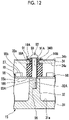
- Fig. 12 is a cross-sectional view of an accommodation casing illustrated in Fig. 11 taken along line F 1 -F 2 .
- Fig. 12 the same components as those of the structure illustrated in Fig. 3 described in the first embodiment are denoted by the same reference signs.
- an electric compressor 90 of the fourth embodiment has the same configuration as that of the electric compressor 10 except that a grommet 91 having a vibration isolation property and a screw 92 are provided instead of the bolt 16 and the vibration isolation member 17 forming the electric compressor 10 of the first embodiment and except that the cover member 34 has a through-hole 34B in which the grommet 91 is disposed.
- the through-hole 34B is provided to penetrate through a portion of the cover member 34 that faces the substrate support portion 32.
- a diameter of the through-hole 34B is sized such that the cover member 34 which partitions a periphery of the through-hole 34B can be accommodated in a ring-shaped groove to be described provided in the grommet 91.
- the grommet 91 has a screw through-hole 91A penetrating through a center of the grommet 91, and a ring-shaped groove 91B.
- the ring-shaped groove 91B is formed by cutting out a part of a side wall of the grommet 91 in a ring shape.
- a portion of the cover member 34 that is inserted into the ring-shaped groove 91B is bonded to the grommet 91 that partitions the ring-shaped groove 91B, by the first adhesive layer 18A.
- an end surface of two end surfaces of the grommet 91 which faces the other surface 55b of the circuit substrate 55 is bonded to the other surface 55b of the circuit substrate 55 by the second adhesive layer 18B.
- a grommet made of rubber can be used as the grommet 91.
- a thickness of the grommet 91 in an extending direction of the screw through-hole 91A is set to be larger than a distance from the other surface 55b of the circuit substrate 55 to the outer surface 34b of the cover member 34. Accordingly, the grommets 91 are disposed on both an inner surface 34a side and an outer surface 34b side of the cover member 34.
- the screw 92 has the same configuration as that of the screw 68 except that the screw 92 includes a shank 95 having a length longer than that of the shank 71 of the screw 68 described with reference to Fig. 7 .
- the length of the shank 95 is set to such a length that the shank 95 can be screwed into the screw hole 32A provided in the substrate support portion 32.
- the screw 92 having the above configuration is screwed into the screw hole 32A in a state where the shank 95 is inserted into the through-hole 34B from outside the cover member 34. Accordingly, the shank 95 penetrates through the grommet 91 and through the second adhesive layer 18B.
- the configuration is such that the grommet 91 having a vibration isolation property that includes the ring-shaped groove 91B accommodating a portion of the cover member 34 located around the through-hole 34B and that is mounted in the through-hole 34B, and the screw 92 that penetrates through the grommet 91 from outside the cover member 34 to be screwed to the substrate support portion 32 are provided, and the grommet 91 is bonded to the other surface 55b of the circuit substrate 55 and to the cover member 34. Therefore, when the cover member 34 is displaced in the direction away from the circuit substrate 55, a state where the grommet 91 is connected to the other surface 55b of the circuit substrate 55 and to the cover member can be maintained.
- vibration of the cover member 34 can be suppressed by the grommet 91, so that noise caused by the vibration of the cover member 34 can be reduced.
- the grommet 91 is disposed not only between the circuit substrate 55 and the cover member 34 but also on an outer side (outer surface 34b) of the cover member 34, the effect of reducing noise caused by vibration of the cover member 34 can be further enhanced.
- the eigenvalue E of the cover member 34 forming the electric compressor 90 of the fourth embodiment may also be set to satisfy the equation (4) described in the first embodiment.
- Fig. 13 is a cross-sectional view of a principal section of an electric compressor according to a modification example of the fourth embodiment of the present invention.
- the same components as those of the structure illustrated in Fig. 12 described in the fourth embodiment are denoted by the same reference signs.
- an electric compressor 100 of a modification example of the fourth embodiment has the same configuration as that of the electric compressor 90 except that the first and second adhesive layers 18A and 18B are eliminated from the configuration of the electric compressor 90 of the fourth embodiment.
- a part of the grommet 91 is disposed on both the inner surface 34a and the outer surface 34b of the cover member 34, and the inner surface 34a and the outer surface 34b of the cover member 34 are in contact with the grommet 91 in a state where the cover member 34 is stationary.
- vibration of the cover member 34 can be suppressed by the simplified configuration without using the first and second adhesive layers 18A and 18B.
- the eigenvalue E of the cover member 34 forming the electric compressor 100 of the modification example of the fourth embodiment may also be set to satisfy the equation (4) described in the first embodiment.
- a grommet having a surging frequency equal to or higher than the frequency of the primary eigenvalue of the cover member 34 may be used as the grommet 91 forming the electric compressor 90 or 100 described above. Noise caused by vibration of the cover member 34 can be reduced by using the grommet 91 having such a configuration.
- Fig. 14 is a cross-sectional view of a principal section of an electric compressor according to a fifth embodiment of the present invention.
- the same components as those of the structure illustrated in Fig. 3 described in the first embodiment are denoted by the same reference signs.
- an electric compressor 110 of the fifth embodiment has the same configuration as that of the electric compressor 10 except that the first and second adhesive layers 18A and 18B are eliminated from the configuration of the electric compressor 10 of the first embodiment and except that the eigenvalue E of the cover member 34 is set to satisfy the equation (4) described in the first embodiment.
- cover member 34 having the eigenvalue E satisfying the equation (4) is applicable to an electric compressor (specifically, an electric compressor in which the first and second adhesive layers 18A and 18B illustrated in Fig. 3 are not provided at both ends of the vibration isolation member 17) other than the structure illustrated in Fig. 14 .
- a vibration isolation member having a surging frequency equal to or higher than the frequency of the primary eigenvalue of the cover member 34 may be used as the vibration isolation member 17 forming the electric compressor 110 described above. Noise caused by vibration of the cover member 34 can be reduced by using the vibration isolation member 17 having such a configuration.
Landscapes
- Engineering & Computer Science (AREA)
- Mechanical Engineering (AREA)
- General Engineering & Computer Science (AREA)
- Compressor (AREA)
- Power Engineering (AREA)
Abstract
Description
- The present invention relates to an electric compressor.
- In the related art, as a compressor for an air conditioner mounted in vehicles such as electric vehicles or hybrid vehicles, an electric compressor in which an inverter device is integrally built-in has been used.
- The electric compressor having such a configuration includes an accommodation casing (inverter box) made of metal that is disposed at an outer periphery of a housing in which an electric motor and a compressor (for example, a scroll compressor) are built-in.
- The inverter device that converts DC power supplied from a high-voltage power supply unit, into three-phase AC power to supply the three-way AC power to the electric motor is built-in inside the accommodation casing.
- The accommodation casing includes an accommodation portion body having an opening into which the inverter device is inserted, and a cover member that is fixed to close the opening of the accommodation portion body.
- The cover member is fixed to the accommodation portion body with bolts or the like to close the opening of the accommodation portion body.
- Since a part of the accommodation portion body is in direct contact with or in contact with the cover member via fastening bolts, the accommodation portion body and the cover member are in metal contact with each other.
- In the case of such a structure where the accommodation portion body and the cover member are in metal contact with each other, when vibration is generated by the compressor or the like, the vibration is transmitted to the cover member via the accommodation portion body, and the cover member vibrates and generates noise, which is a problem.
- As a technique intended to solve such a problem, there is an electric compressor disclosed in PTL 1.
- PTL 1 discloses an electric compressor including an accommodation portion body which has an opening and inside which an inverter device is accommodated and installed; a cover member that covers the opening; and a gasket that is interposed between the accommodation portion body and the cover member to seal a gap between the accommodation portion body and the cover member. The gasket includes a flat metal core material and a foamed elastic body provided to cover both surfaces of the core material, and has concavities and convexities of a predetermined shape provided by embossing. The accommodation portion body and the cover member are fastened with bolts, and the concavities and convexities imparted to the gasket are disposed to be closer to an inside of the accommodation portion body than the bolts.
- [PTL 1]
Japanese Patent No. 5653695 - However, in the electric compressor disclosed in PTL 1, since the accommodation portion body and the cover member are configured to be fastened with the bolts via the gasket, when the cover member is displaced in a direction away from the accommodation portion body and the gasket is separated from the gasket or the accommodation portion body, it is difficult for the gasket to isolate vibration of the cover member, and noise caused by vibration of the cover member cannot be reduced, which is a concern.
- Therefore, an object of the present invention is to provide an electric compressor capable of reducing noise caused by vibration of a cover member.
- In order to solve the above problem, according to a first aspect of the present invention, there is provided an electric compressor including: a housing that accommodates a compressor and an electric motor that drives the compressor; an inverter device including a circuit substrate on which an electronic component is mounted; an accommodation casing including an accommodation portion body provided on a side surface of the housing to accommodate the inverter device, a substrate support portion that protrudes to an inside of the accommodation portion body to support one surface of the circuit substrate, and a cover member fixed to the accommodation portion body to close an opening of the accommodation portion body; a bolt which is fastened to the substrate support portion to restrict a position of the circuit substrate with respect to the substrate support portion, and in which one surface of a head facing an inner surface of the cover member is flat; and a first vibration isolation member that is disposed between the one surface of the head and the inner surface of the cover member and that is bonded to the one surface of the head and to the inner surface of the cover member.
- According to the present invention, since the first vibration isolation member is provided that is disposed between the one surface (flat surface) of the head of the bolt and the inner surface of the cover member and that is bonded to the one surface of the head and to the inner surface of the cover member, when the cover member is displaced in a direction away from the head of the bolt, a state where the first vibration isolation member is connected to the head and to the cover member can be maintained.
- Accordingly, the state where the first vibration isolation member is connected to the head and to the cover member can be maintained without depending on displacement directions of the cover member (in this case, a direction where the cover member is separated from the head of the bolt and a direction where the cover member approaches the head of the bolt). Accordingly, when the cover member vibrates, the vibration of the cover member can be suppressed by the first vibration isolation member, so that noise caused by the vibration of the cover member can be reduced.
- In the electric compressor according to the first aspect of the present invention, the head may be provided with a screw hole, and a gasket disposed on an outer surface of the cover member, and a screw screwed into the screw hole via the gasket may be provided.
- According to the present invention, since the gasket having a vibration isolation function that is disposed on the outer surface of the cover member, and the screw that is screwed into the screw hole provided in the head via the gasket are provided, when the cover member is displaced in the direction away from the head of the bolt, the state where the first vibration isolation member is connected to the head and to the cover member can be maintained without bonding the first vibration isolation member to the one surface of the head and to the inner surface of the cover member.
- Accordingly, the state where the first vibration isolation member is connected to the head and to the cover member can be maintained without depending on displacement directions of the cover member (in this case, a direction where the cover member is separated from the head of the bolt and a direction where the cover member approaches the head of the bolt). Therefore, when the cover member vibrates, the vibration of the cover member can be suppressed by the first vibration isolation member, so that noise caused by the vibration of the cover member can be reduced.
- In the electric compressor according to the first aspect of the present invention, the gasket may be made of rubber.
- In such a manner, when the gasket made of rubber is used, vibration of the cover member can be suppressed by using the first vibration isolation member and the gasket, so that the effect of reducing noise caused by the vibration of the cover member can be further enhanced.
- In the electric compressor according to the first aspect of the present invention, the gasket may have a surging frequency equal to or higher than a frequency of a primary eigenvalue of the cover member.
- In such a manner, since the gasket is used that has a surging frequency equal to or higher than the frequency of the primary eigenvalue of the cover member, the effect of reducing noise caused by vibration of the cover member can be enhanced.
- In the electric compressor according to the first aspect of the present invention, the head may be provided with a screw hole, and a screw may be provided that penetrates through the cover member and through the first vibration isolation member from outside the cover member to be screwed into the screw hole.
- In such a manner, since the screw is provided that penetrates through the cover member and through the first vibration isolation member from outside the cover member to be screwed into the screw hole provided in the head of the bolt, the position of the cover member in the direction away from the head of the bolt can be restricted, and the strength of connection between the inner surface of the cover member and the first vibration isolation member can be increased.
- Accordingly, the effect of suppressing vibration of the cover member can be enhanced, so that the effect of reducing noise caused by the vibration of the cover member can be enhanced.
- According to a second aspect of the present invention, there is provided an electric compressor including: a housing that accommodates a compressor and an electric motor that drives the compressor; an inverter device including a circuit substrate on which an electronic component is mounted; an accommodation casing including an accommodation portion body provided on a side surface of the housing to accommodate the inverter device, a substrate support portion that protrudes to an inside of the accommodation portion body to support one surface of the circuit substrate, and a cover member fixed to the accommodation portion body to close an opening of the accommodation portion body; a bolt which is fastened to the substrate support portion to restrict a position of the circuit substrate with respect to the substrate support portion, and in which one surface of a head facing an inner surface of the cover member is flat; and a second vibration isolation member that is disposed between the one surface of the head and the inner surface of the cover member and that has a surging frequency equal to or higher than a frequency of a primary eigenvalue of the cover member.
- In such a manner, since the second vibration isolation member is provided that is disposed between the one surface of the head of the bolt and the inner surface of the cover member and that has a surging frequency equal to or higher than the frequency of the primary eigenvalue of the cover member, noise caused by vibration of the cover member can be reduced without bonding the second vibration isolation member to the one surface of the head of the bolt and to the inner surface of the cover member.
- In the electric compressor according to the second aspect of the present invention, the head may be provided with a screw hole, and a screw may be provided that penetrates through the cover member and through the second vibration isolation member from outside the cover member to be screwed into the screw hole.
- In such a manner, since the screw is provided that penetrates through the cover member and through the second vibration isolation member from outside the cover member to be screwed into the screw hole provided in the head of the bolt, the position of the cover member in the direction away from the head of the bolt can be restricted, and the strength of connection between the inner surface of the cover member and the second vibration isolation member can be increased.
- Accordingly, the effect of suppressing vibration of the cover member can be enhanced, so that the effect of reducing noise caused by the vibration of the cover member can be enhanced.
- The electric compressor according to the second aspect of the present invention may further include a gasket disposed on an outer surface of the cover member, and the screw may be screwed into the screw hole via the gasket.
- In such a manner, since the gasket disposed on the outer surface of the cover member is provided and the screw is screwed into the screw hole via the gasket, when the gasket is made of metal, the loosening of the screw can be prevented.
- In the electric compressor according to the second aspect of the present invention, the gasket may be made of rubber.
- In such a manner, when the gasket made of rubber is used, vibration of the cover member can be suppressed by using the second vibration isolation member and the gasket, so that the effect of reducing noise caused by the vibration of the cover member can be further enhanced.
- According to a third aspect of the present invention, there is provided an electric compressor including: a housing that accommodates a compressor and an electric motor that drives the compressor; an inverter device including a circuit substrate on which an electronic component is mounted; and an accommodation casing including an accommodation portion body provided on a side surface of the housing to accommodate the inverter device, a substrate support portion that protrudes to an inside of the accommodation portion body to support one surface of the circuit substrate, and a cover member fixed to the accommodation portion body to close an opening of the accommodation portion body. The cover member includes a through-hole at a portion facing the substrate support portion. A grommet having a vibration isolation property that includes a ring-shaped groove accommodating the cover member located around the through-hole and that is mounted in the through-hole, and a screw that penetrates through the grommet from outside the cover member to be screwed to the substrate support portion are provided.
- According to the present invention, since the grommet having a vibration isolation property that includes the ring-shaped groove accommodating the cover member located around the through-hole provided in the cover member and that is mounted in the through-hole, and the screw that penetrates through the grommet from outside the cover member to be screwed to the substrate support portion are provided, when the cover member is displaced in the direction away from the head of the bolt, a state where the grommet is connected to the other surface of the circuit substrate and to the cover member can be maintained. Therefore, noise caused by vibration of the cover member can be reduced.
- In addition, since a part of the grommet is disposed not only between the circuit substrate and the cover member but also on an outer side of the cover member, the effect of reducing noise caused by vibration of the cover member can be further enhanced.
- In the electric compressor according to the third aspect of the present invention, the grommet may be bonded to the other surface of the circuit substrate and to the cover member.
- According to the present invention, since the grommet is bonded to the other surface of the circuit substrate and to the cover member, when the cover member is displaced in the direction away from the circuit substrate, the state where the grommet is connected to the other surface of the circuit substrate and to the cover member can be maintained.
- Accordingly, vibration of the cover member can be suppressed by the grommet, so that noise caused by the vibration of the cover member can be reduced.
- In addition, since a part of the grommet is disposed not only between the circuit substrate and the cover member but also on the outer side of the cover member, the effect of reducing noise caused by vibration of the cover member can be further enhanced.
- In the electric compressor according to the third aspect of the present invention, the grommet may have a surging frequency equal to or higher than a frequency of a primary eigenvalue of the cover member.
- In such a manner, since the grommet is used that has a surging frequency equal to or higher than the frequency of the primary eigenvalue of the cover member, the effect of reducing noise caused by vibration of the cover member can be enhanced without bonding the grommet to the circuit substrate and to the cover member.
- In the electric compressor according to the first to third aspects of the present invention, the compressor may include a fixed scroll and a movable scroll each having a spiral shape, a plurality of compression chambers that are formed between the fixed scroll and the movable scroll to compress a refrigerant by means of a movement of the movable scroll, and a discharge port that discharges the compressed refrigerant. When an average value of a length S1 (mm) of an inner curved line of the fixed scroll in a stage where the compressor discharges the refrigerant from the discharge port, the fixed scroll partitioning a compression chamber formed on an innermost side among the plurality of compression chambers, and of a length S2 (mm) of an outer curved line of the movable scroll that partitions the compression chamber formed on the innermost side is an average value SAV (mm), an eigenvalue E (kHz) of the cover member may satisfy the following equation (1):

- In such a manner, since the eigenvalue E of the cover member is set to satisfy the equation (1), when vibration of the compressor is transmitted to the accommodation portion body, the vibration of the cover member can be suppressed by the first or second vibration isolation member. Accordingly, noise caused by the vibration of the cover member can be reduced.
- According to a fourth aspect of the present invention, there is provided an electric compressor including: a housing that accommodates a compressor and an electric motor that drives the compressor; an inverter device including a circuit substrate on which an electronic component is mounted; an accommodation casing including an accommodation portion body provided on a side surface of the housing to accommodate the inverter device, a substrate support portion that protrudes to an inside of the accommodation portion body to support one surface of the circuit substrate, and a cover member fixed to the accommodation portion body to close an opening of the accommodation portion body; and a third vibration isolation member that is in contact with an inner surface of the cover member. The compressor includes a fixed scroll and a movable scroll each having a spiral shape, a plurality of compression chambers that are formed between the fixed scroll and the movable scroll to compress a refrigerant by means of a movement of the movable scroll, and a discharge port that discharges the compressed refrigerant. When an average value of a length S1 (mm) of an inner curved line of the fixed scroll in a stage where the compressor discharges the refrigerant from the discharge port, the fixed scroll partitioning a compression chamber formed on an innermost side among the plurality of compression chambers, and of a length S2 (mm) of an outer curved line of the movable scroll that partitions the compression chamber formed on the innermost side is an average value SAV (mm), an eigenvalue E (kHz) of the cover member satisfies the following equation (2):

- Fluid sound in a cylinder of the scroll compressor is generated by a relationship between a representative length of the compression chambers and the sound speed. The representative length is a length equivalent to a length of an innermost circumference of the scroll compression chamber. Therefore, the eigenvalue E (kHz) of the cover may be equal to or more than an eigenvalue of the fluid sound in the cylinder.
- Since the eigenvalue of the cover member is set to satisfy the equation (2), with the simple configuration, vibration of the cover member can be suppressed by using the third vibration isolation member. Accordingly, noise caused by the vibration of the cover member can be reduced.
- The inner curved line of the fixed scroll may be referred to as a ventral side curved line. In addition, the outer curved line of the movable scroll may be referred to as a dorsal side curved line.
- According to the present invention, noise caused by vibration of the cover member can be reduced.
-
-
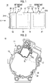
Fig. 1 is a side view illustrating a schematic configuration of an electric compressor according to a first embodiment of the present invention. -
Fig. 2 is a side view of the electric compressor illustrated inFig. 1 as viewed from A. -
Fig. 3 is a cross-sectional view of an accommodation casing illustrated inFig. 2 that accommodates an inverter device illustrated inFig. 1 , taken along line B1-B2. -
Fig. 4 is a cross-sectional view illustrating an internal structure of a compressor illustrated inFig. 1 . -
Fig. 5 is a view schematically illustrating a discharge port and a compression chamber formed at a position closest to the discharge port among a plurality of compression chambers in the state illustrated inFig. 4 (stage where a refrigerant gas is discharged). -
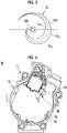
Fig. 6 is a side view illustrating a schematic configuration of an electric compressor according to a second embodiment of the present invention. -
Fig. 7 is a cross-sectional view of an accommodation casing illustrated inFig. 6 taken along line C1-C2. -
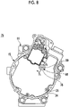
Fig. 8 is a side view illustrating a schematic configuration of an electric compressor according to a third embodiment of the present invention. -
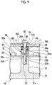
Fig. 9 is a cross-sectional view of an accommodation casing illustrated inFig. 8 taken along line D1-D2. -
Fig. 10 is a cross-sectional view of a principal section of an electric compressor according to a modification example of the third embodiment of the present invention. -
Fig. 11 is a side view illustrating a schematic configuration of an electric compressor according to a fourth embodiment of the present invention. -
Fig. 12 is a cross-sectional view of an accommodation casing illustrated inFig. 11 taken along line F1-F2. -
Fig. 13 is a cross-sectional view of a principal section of an electric compressor according to a -
Fig. 14 is a cross-sectional view of a principal section of an electric compressor according to a fifth embodiment of the present invention. - Hereinafter, embodiments to which the present invention is applied will be described in detail with reference to the drawings. The drawings to be used in the following description are for describing configurations of the embodiments of the present invention, and the size, thickness, dimension and the like of each portion illustrated may be different from a dimensional relationship of an actual electric compressor.
-
-
Fig. 1 is a side view illustrating a schematic configuration of an electric compressor according to a first embodiment of the present invention.Fig. 1 illustrates an inverter-integrated electric compressor to be used in a vehicle air conditioner, as one example of anelectric compressor 10. -
Fig. 2 is a side view of the electric compressor illustrated inFig. 1 as viewed from A. InFig. 2 , the same components as those of the structure illustrated inFig. 1 are denoted by the same reference signs. -
Fig. 3 is a cross-sectional view of an accommodation casing illustrated inFig. 2 that accommodates an inverter device illustrated inFig. 1 , taken along line B1-B2. InFig. 3 , the same components as those of the structure illustrated inFigs. 1 and 2 are denoted by the same reference signs. - Referring to
Figs. 1 to 3 , theelectric compressor 10 of the first embodiment includes ahousing 11, anelectric motor 12, acompressor 13, amotor shaft 14, anaccommodation casing 15, abolt 16, avibration isolation member 17, a firstadhesive layer 18A, a secondadhesive layer 18B, and aninverter device 19. - The
housing 11 includes afirst housing portion 21 and asecond housing portion 22. Thefirst housing portion 21 includes a housingmain body 24 that accommodates theelectric motor 12, and arefrigerant suction port 25 provided in the housingmain body 24. - The
refrigerant suction port 25 introduces the refrigerant gas (refrigerant) of low temperature and low pressure into the housingmain body 24 from outside thehousing 11. The refrigerant gas of low temperature and low pressure introduced into the housingmain body 24 flows around theelectric motor 12, flows into thesecond housing portion 22, and then is suctioned into and compressed by thecompressor 13. - The
second housing portion 22 includes a housingmain body 27 that accommodates thecompressor 13, and adischarge portion 28 that is provided in the housingmain body 27 to discharge the refrigerant gas. The housingmain body 27 is fastened and fixed to the housingmain body 24 using a plurality of bolts (not illustrated). Accordingly, thefirst housing portion 21 and thesecond housing portion 22 are integrally configured. - The
housing 11 is configured such that the refrigerant in thefirst housing portion 21 is movable into thesecond housing portion 22. Thedischarge portion 28 includes adischarge port 28A that extends to a central portion of thecompressor 13 to discharge the compressed refrigerant gas. Thedischarge port 28A forms a part of thecompressor 13. - The
discharge portion 28 having the above configuration discharges the refrigerant of high temperature and high pressure compressed and generated by thecompressor 13, to the outside of thehousing 11. - The
housing 11 having the above configuration functions as a pressure resistant container. For example, die cast aluminum can be used as a material of thehousing 11. - The
electric motor 12 is connected to one end of themotor shaft 14. Theelectric motor 12 drives thecompressor 13 via themotor shaft 14. -
Fig. 4 is a cross-sectional view illustrating an internal structure of the compressor illustrated inFig. 1 .Fig. 4 illustrates a scroll compressor as one example of thecompressor 13. Thecompressor 13 illustrated inFig. 4 schematically illustrates a state where the refrigerant gas of high temperature and high pressure is discharged from thedischarge port 28A. - In addition,
Fig. 4 illustrates a state where a position angle θ of amovable scroll 42 with respect to the position of a fixedscroll 41 is 230°. The position angle θ is an angle indicating the position of themovable scroll 42 with respect to a back side winding end of the fixedscroll 41. - Further,
Fig. 4 illustrates a compression chamber that is formed at a position closest to thedischarge port 28A among a plurality ofcompression chambers 44 in a refrigerant gas discharge stage, as acompression chamber 44A. InFig. 4 , the same components as those of the structure illustrated inFigs. 1 to 3 are denoted by the same reference signs. - Referring to
Figs. 1 and4 , thecompressor 13 is a scroll compressor and is connected to the other end of themotor shaft 14. - The
compressor 13 includes the fixedscroll 41 having a spiral shape; themovable scroll 42 each having a spiral shape; the plurality ofcompression chambers 44 that are formed between the fixedscroll 41 and themovable scroll 42 to compress the refrigerant gas by means of movement of the movable scroll 42 (including thecompression chamber 44A); and thedischarge port 28A that faces a central portion of the fixedscroll 41 to discharge the compressed refrigerant gas. - The
compressor 13 compresses the refrigerant gas of low temperature and low pressure in a direction toward a center of thecompressor 13 using the plurality ofcompression chambers 44 that are changed in shape by movement of themovable scroll 42, thereby generating the refrigerant gas of high temperature and high pressure. - Then, the refrigerant gas of high temperature and high pressure is guided to the
discharge port 28A disposed at the center of the compressor 13 (center of the fixed scroll 41), and is supplied to the outside of theelectric compressor 10 via thedischarge port 28A. - The
accommodation casing 15 is a metal casing, and includes anaccommodation portion body 31, asubstrate support portion 32, acover member 34, and a plurality ofscrews 35. - The
accommodation portion body 31 is provided on a side surface of the first housing portion 21 (side surface of the housing 11). Theaccommodation portion body 31 has anopening 31A. Theaccommodation portion body 31 accommodates theinverter device 19. - The
substrate support portion 32 is provided on abottom surface 31a of theaccommodation portion body 31. Thesubstrate support portion 32 protrudes in a direction orthogonal to thebottom surface 31a of theaccommodation portion body 31. Namely, thesubstrate support portion 32 protrudes to an inside of theaccommodation portion body 31. Atip surface 32a of thesubstrate support portion 32 is a flat surface. Thetip surface 32a of thesubstrate support portion 32 supports onesurface 55a of acircuit substrate 55 to be described later that forms theinverter device 19. - The
substrate support portion 32 has ascrew hole 32A to which thebolt 16 is fastened. Thescrew hole 32A is exposed from thetip surface 32a, and extends in the direction orthogonal to thebottom surface 31a. - The
cover member 34 is a plate-shaped member, and is disposed on theaccommodation portion body 31 to close theopening 31A. Thecover member 34 has aninner surface 34a disposed on anaccommodation portion body 31 side, and anouter surface 34b disposed on a side opposite theinner surface 34a. In addition, thecover member 34 has a plurality of screw holes (not illustrated) in an outer peripheral portion of thecover member 34. - Shanks of the plurality of
screws 35 are screwed into the screw holes formed in thecover member 34 and to an edge portion of theaccommodation portion body 31 that faces the screw holes of thecover member 34. Accordingly, thecover member 34 is fixed to theaccommodation portion body 31. - Referring to
Fig. 3 , thebolt 16 includes ahead 51 and ashank 52 that is male threaded. Thehead 51 has onesurface 51a and theother surface 51b on which theshank 52 is provided. The onesurface 51a is a flat surface and has a circular shape. Theother surface 51b is a flat surface disposed on a side opposite the onesurface 51a. - The
shank 52 of thebolt 16 is fastened to thescrew hole 32A provided in thesubstrate support portion 32 in a state where theshank 52 is inserted into a through-hole 55A formed in thecircuit substrate 55. Accordingly, thecircuit substrate 55 is fixed to thesubstrate support portion 32 with thebolt 16. - The
vibration isolation member 17 is provided between the onesurface 51a of thehead 51 and theinner surface 34a of thecover member 34. Thevibration isolation member 17 is a member that suppresses vibration of thecover member 34 when vibration generated from thecompressor 13 is transmitted to thecover member 34. For example, a vibration isolation rubber (vibration isolation member made of rubber) can be used as thevibration isolation member 17. - When a vibration isolation rubber is used as the
vibration isolation member 17, a thickness of thevibration isolation member 17 can be set within, for example, a range of 2 mm to 20 mm. - The
vibration isolation member 17 has onesurface 17a facing the onesurface 51a of thehead 51, and theother surface 17b facing theinner surface 34a of thecover member 34. The onesurface 17a and theother surface 17b are flat surfaces. Theother surface 17b is a surface disposed on a side opposite the onesurface 17a. - The one
surface 17a of thevibration isolation member 17 is bonded to the onesurface 51a of thehead 51 via the firstadhesive layer 18A. Theother surface 17b of thevibration isolation member 17 is bonded to theinner surface 34a of thecover member 34 via the secondadhesive layer 18B. - For example, vulcanizing adhesive agents, moisture-curing adhesive agents, or the like can be used as the first and second
adhesive layers - In such a manner, since the
vibration isolation member 17 is provided that is disposed between the onesurface 51a (flat surface) of thehead 51 of thebolt 16 and theinner surface 34a of thecover member 34 and that is bonded to the onesurface 51a of thehead 51 and to theinner surface 34a of thecover member 34, even when thecover member 34 is displaced in a direction away from thehead 51 of thebolt 16, a state where thevibration isolation member 17 is connected to thehead 51 and to thecover member 34 can be maintained. - Accordingly, the state where the
vibration isolation member 17 is connected to thehead 51 and to thecover member 34 can be maintained without depending on displacement directions of the cover member 34 (in this case, a direction where thecover member 34 is separated from thehead 51 of thebolt 16 and a direction where thecover member 34 approaches thehead 51 of the bolt 16). - Therefore, when the
cover member 34 vibrates, the vibration of thecover member 34 can be suppressed by thevibration isolation member 17, so that noise caused by the vibration of thecover member 34 can be reduced. - A shape of the
vibration isolation member 17 can be, for example, a circular columnar shape having a diameter equal to a diameter of the onesurface 51a of thehead 51 having a circular shape. In this case, shapes of the onesurface 17a and theother surface 17b of thevibration isolation member 17 are a circular shape. - In
Fig. 3 , the case where thevibration isolation member 17 is bonded to the onesurface 51a of thehead 51 and to theinner surface 34a of thecover member 34 using the first and secondadhesive layers vibration isolation member 17 itself is a material having a tackiness property and an adhesive property, thevibration isolation member 17 may be bonded to the onesurface 51a of thehead 51 and to theinner surface 34a of thecover member 34 without using the first and secondadhesive layers - The
inverter device 19 is accommodated in theaccommodation casing 15. Theinverter device 19 includes high-voltage components (not illustrated), a power substrate (not illustrated), aCPU substrate 58 including anelectronic component 57 and thecircuit substrate 55, and an inverter module (not illustrated). - For example, components such as a smoothing capacitor, a normal mode coil, and a common mode coil provided in a high-voltage power supply line (not illustrated) can be used as the high-voltage components (not illustrated).
- A structure formed of, for example, a circuit substrate, a plurality of power semiconductor switching elements (IGBTs) mounted on the circuit substrate, and a power control circuit that operates the power semiconductor switching elements can be used as the power substrate (not illustrated).
- The
circuit substrate 55 includes a substrate body (not illustrated) and a circuit pattern (not illustrated) formed on the substrate body. Thecircuit substrate 55 is fixed to thetip surface 32a of thesubstrate support portion 32. - The
circuit substrate 55 has the onesurface 55a that is in contact with thetip surface 32a of thesubstrate support portion 32; theother surface 55b facing theinner surface 34a of thecover member 34; and the through-hole 55A into which theshank 52 of thebolt 16 is inserted. - The
electronic component 57 is mounted on theother surface 55b of thecircuit substrate 55. For example, an element such as a CPU that operates at a low voltage can be used as theelectronic component 57. -
Fig. 5 is a view schematically illustrating the discharge port and the compression chamber that is formed at the position closest to the discharge port among the plurality of compression chambers in the state (refrigerant gas discharge state) illustrated inFig. 4 . InFig. 5 , the same components as those of the structure illustrated inFig. 4 are denoted by the same reference signs. - Here, an exemplary eigenvalue E of the
cover member 34 will be described with reference toFigs. 1 ,4 , and5 . - Referring to
Fig. 5 , an average value SAV (mm) of a length S1 (mm) of an inner curved line CL1 of the fixedscroll 41 that partitions thecompression chamber 44A formed on an innermost side among the plurality ofcompression chambers 44 in a stage where thecompressor 13 discharges the refrigerant gas (refrigerant) from thedischarge port 28A (state illustrated inFig. 4 ), and of a length S2 (mm) of an outer curved line CL2 of themovable scroll 42 that partitions thecompression chamber 44A formed on the innermost side is calculated by the following equation (3). The average value SAV (representative length) is a value corresponding to a length of a center curved line CL3 illustrated inFig. 5 .
- Then, the eigenvalue E (kHz) of the
cover member 34 may be set to satisfy the following equation (4).
- However, in the equation (4), V (m/s) is a sound speed of the refrigerant gas (refrigerant).
- In such a manner, since the eigenvalue E of the
cover member 34 is set to satisfy the equation (4), when vibration of thecompressor 13 is transmitted to theaccommodation portion body 31, the vibration of thecover member 34 can be suppressed by thevibration isolation member 17, so that noise caused by the vibration of thecover member 34 can be reduced. - In addition, since the
cover member 34 having the eigenvalue E satisfying the equation (4), and thevibration isolation member 17 bonded to the onesurface 51a of thehead 51 and to theinner surface 34a of thecover member 34 are provided, the effect of suppressing vibration of thecover member 34 can be enhanced, so that noise caused by the vibration of thecover member 34 can be further reduced. - Here, a specific example of the eigenvalue E (kHz) of the
cover member 34 will be described. - When R-134a that is a fluorine-based refrigerant is used as the refrigerant gas (refrigerant), a sound speed V of the refrigerant is approximately 150 m/s to 180 m/s.
- In a case where a 33cc scroll compressor is used as the
compressor 13 for a vehicle air conditioner, when the length S1 is 79.97 mm and the length S2 is 103.09 mm, the average value SAV of these two lengths is 91.53 mm. - When V = 180 m/s, SAV = 91.53 mm, and V = 180 m/s are substituted into the equation (4), E ≥ 1.97 (kHz).
- Therefore, in the case of the above-described conditions, when the eigenvalue E of the
cover member 34 is 1.97 kHz or more, vibration of thecover member 34 can be suppressed, and noise caused by the vibration of thecover member 34 can be reduced. - According to the
electric compressor 10 of the first embodiment, since thevibration isolation member 17 is provided that is disposed between the onesurface 51a (flat surface) of thehead 51 of thebolt 16 and theinner surface 34a of thecover member 34 and that is bonded to the onesurface 51a of thehead 51 and to theinner surface 34a of thecover member 34, when thecover member 34 is displaced in the direction away from thehead 51 of thebolt 16, the state where thevibration isolation member 17 is connected to thehead 51 and to thecover member 34 can be maintained. - Accordingly, when vibration of the
compressor 13 is transmitted to theaccommodation portion body 31, thevibration isolation member 17 is capable of suppressing vibration of thecover member 34 without depending on the displacement directions of the cover member 34 (in this case, the direction where thecover member 34 is separated from thehead 51 of thebolt 16 and the direction where thecover member 34 approaches thehead 51 of the bolt 16), so that noise caused by the vibration of thecover member 34 can be reduced. - In the
electric compressor 10 of the first embodiment, the case where theinner surface 34a of thecover member 34 and the onesurface 51a of thehead 51 are bonded to thevibration isolation member 17 using the first and secondadhesive layers vibration isolation member 17, a vibration isolation member having a surging frequency equal to or higher than the frequency of the primary eigenvalue of the cover member 34 (equal to or higher than a frequency that has to be damped) may be used as thevibration isolation member 17 without bonding theinner surface 34a of thecover member 34 and the onesurface 51a of thehead 51 to thevibration isolation member 17. - In such a manner, since the
vibration isolation member 17 is provided that is disposed between the onesurface 51a of thehead 51 of thebolt 16 and theinner surface 34a of thecover member 34 and that has a surging frequency equal to or higher than the frequency of the primary eigenvalue of thecover member 34, thevibration isolation member 17 is capable of fully following a displacement of thecover member 34 even without bonding the onesurface 51a of thehead 51 of thebolt 16 and theinner surface 34a of thecover member 34 to thevibration isolation member 17, so that noise caused by vibration of thecover member 34 can be reduced. - In addition, when the first and second
adhesive layers cover member 34 can be further reduced by using thevibration isolation member 17. - When the first and second
adhesive layers cover member 34. -
Fig. 6 is a side view illustrating a schematic configuration of an electric compressor according to a second embodiment of the present invention. InFig. 6 , the same components as those of the structure illustrated inFig. 1 are denoted by the same reference signs. -
Fig. 7 is a cross-sectional view of an accommodation casing illustrated inFig. 6 taken along line C1-C2. InFig. 7 , the same components as those of the structure illustrated inFig. 3 described in the first embodiment are denoted by the same reference signs. - Referring to
Figs. 6 and7 , anelectric compressor 65 of the second embodiment has the same configuration as that of theelectric compressor 10 except that abolt 66 is provided instead of thebolt 16 forming theelectric compressor 10 of the first embodiment and except that theelectric compressor 65 includes a through-hole 34A provided in thecover member 34 and ascrew 68. - The
bolt 66 has the same configuration as that of thebolt 16 except that thehead 51 has ascrew hole 51A. Thebolt 66 is fastened to thescrew hole 32A of thesubstrate support portion 32 in a state where thebolt 66 is inserted into the through-hole 55A provided in thecircuit substrate 55. - The
screw hole 51A is exposed from the onesurface 51a of thehead 51, and extends in a direction from the onesurface 51a toward theshank 52. A depth of thescrew hole 51A is smaller than a thickness of thehead 51. - The through-
hole 34A is formed to penetrate through a portion of thecover member 34 that faces thescrew hole 51A. - The
screw 68 includes ahead 69 and ashank 71 integrated with thehead 69. Thescrew 68 is screwed into thescrew hole 51A provided in thehead 51 in a state where theshank 71 is inserted into the through-hole 34A from outside thecover member 34. In this state, theshank 71 of thescrew 68 penetrates through the firstadhesive layer 18A, through thevibration isolation member 17, and through the secondadhesive layer 18B. - According to the
electric compressor 65 of the second embodiment, in addition to thevibration isolation member 17, the firstadhesive layer 18A, and the secondadhesive layer 18B, thescrew 68 is provided that penetrates through thecover member 34 and through thevibration isolation member 17 from outside thecover member 34 to be screwed into thescrew hole 51A provided in thehead 51 of thebolt 66, so that the position of thecover member 34 in the direction away from thehead 51 can be restricted, and the strength of connection between theinner surface 34a of thecover member 34 and thevibration isolation member 17 can be increased. - Accordingly, the effect of suppressing vibration of the
cover member 34 can be enhanced, so that the effect of reducing noise caused by the vibration of thecover member 34 can be enhanced. - In addition, the eigenvalue E of the
cover member 34 forming theelectric compressor 65 of the second embodiment may be set to satisfy the equation (4) described in the first embodiment. - In the
electric compressor 65 of the second embodiment, the case where theinner surface 34a of thecover member 34 and the onesurface 51a of thehead 51 are bonded to thevibration isolation member 17 using the first and secondadhesive layers vibration isolation member 17 without bonding theinner surface 34a of thecover member 34 and the onesurface 51a of thehead 51 to thevibration isolation member 17. - In such a manner, since the
vibration isolation member 17 is provided that is disposed between the onesurface 51a of thehead 51 of thebolt 16 and theinner surface 34a of thecover member 34 and that has a surging frequency equal to or higher than the frequency of the primary eigenvalue of thecover member 34, thevibration isolation member 17 is capable of fully following a displacement of thecover member 34 even without bonding the onesurface 51a of thehead 51 of thebolt 16 and theinner surface 34a of thecover member 34 to thevibration isolation member 17, so that noise caused by vibration of thecover member 34 can be reduced. - In addition, when the first and second
adhesive layers cover member 34 can be further reduced by using thevibration isolation member 17. - When the first and second
adhesive layers cover member 34. -
Fig. 8 is a side view illustrating a schematic configuration of an electric compressor according to a third embodiment of the present invention. InFig. 8 , the same components as those of the structure illustrated inFig. 6 are denoted by the same reference signs. -
Fig. 9 is a cross-sectional view of an accommodation casing illustrated inFig. 8 taken along line D1-D2. InFig. 9 , the same components as those of the structure illustrated inFig. 7 described in the second embodiment are denoted by the same reference signs. - Referring to
Figs. 8 and9 , anelectric compressor 75 of the third embodiment has the same configuration as that of theelectric compressor 65 except that agasket 78 is further provided to the configuration of theelectric compressor 65 of the second embodiment. - The
gasket 78 has a hole (not illustrated) through which theshank 71 of thescrew 68 is capable of passing. Thegasket 78 is disposed on theouter surface 34b of thecover member 34 such that the hole faces the through-hole 34A provided in thecover member 34. - For example, a gasket of which a surface is coated with rubber can be used as the
gasket 78. - The
screw 68 is screwed into thescrew hole 51A via thegasket 78, thecover member 34, the firstadhesive layer 18A, thevibration isolation member 17, and the secondadhesive layer 18B. - According to the
electric compressor 75 of the third embodiment, since thegasket 78 disposed on theouter surface 34b of thecover member 34 is provided and thescrew 68 is screwed into thescrew hole 51A via thegasket 78, when thegasket 78 is made of metal, the loosening of thescrew 68 can be prevented. In addition, when thegasket 78 is made of rubber, vibration of thecover member 34 can be suppressed by using thevibration isolation member 17 and thegasket 78, so that the effect of reducing noise caused by the vibration of thecover member 34 can be further enhanced. - The eigenvalue E of the
cover member 34 forming theelectric compressor 75 of the third embodiment may also be set to satisfy the equation (4) described in the first embodiment. -
Fig. 10 is a cross-sectional view of a principal section of an electric compressor according to a modification example of the third embodiment of the present invention. InFig. 10 , the same components as those of the structure illustrated inFig. 7 described in the third embodiment are denoted by the same reference signs. - Referring to
Fig. 10 , anelectric compressor 85 of a modification example of the third embodiment has the same configuration as that of theelectric compressor 75 except that the first and secondadhesive layers electric compressor 75 of the third embodiment and a gasket having a vibration isolation function is used as thegasket 78. For example, a gasket of which a surface is coated with rubber can be used as thegasket 78. - Namely, in the
electric compressor 85, in a state where thecover member 34 is stationary, theinner surface 34a of thecover member 34 and the onesurface 51a of thehead 51 are in contact with thevibration isolation member 17, and theouter surface 34b of thecover member 34 and thegasket 78 are in contact with each other. - Therefore, when the
cover member 34 vibrates and thecover member 34 is displaced from a stationary position in a direction where thecover member 34 approaches thehead 69, even if thevibration isolation member 17 is separated from theinner surface 34a of thecover member 34, vibration of thecover member 34 can be suppressed by thegasket 78 since thegasket 78 abuts on thehead 69 and on theouter surface 34b of thecover member 34. - On the other hand, when the
cover member 34 vibrates and thecover member 34 is displaced from the stationary position in a direction away from the head 69 (direction toward the circuit substrate 55), even if thegasket 78 is separated from theouter surface 34b of thecover member 34, vibration of thecover member 34 can be suppressed by thevibration isolation member 17 since thevibration isolation member 17 abuts on the onesurface 51a of thehead 51 and on theinner surface 34a of thecover member 34. - Namely, according to the
electric compressor 85 of the modification example of the third embodiment, vibration of thecover member 34 can be suppressed by the simplified configuration without using the first and secondadhesive layers vibration isolation member 17 to thehead 51 of thebolt 66 and to theinner surface 34a of the cover member 34). - The eigenvalue E of the
cover member 34 forming theelectric compressor 85 of the modification example of the third embodiment may also be set to satisfy the equation (4) described in the first embodiment. - For example, a gasket having a surging frequency equal to or higher than the frequency of the primary eigenvalue of the cover member 34 (equal to or higher than a frequency that has to be damped) may be used as the
gasket 78 forming theelectric compressor cover member 34 can be reduced by using thegasket 78 having such a configuration. -
Fig. 11 is a side view illustrating a schematic configuration of an electric compressor according to a fourth embodiment of the present invention. InFig. 11 , the same components as those of the structure illustrated inFig. 3 are denoted by the same reference signs. -
Fig. 12 is a cross-sectional view of an accommodation casing illustrated inFig. 11 taken along line F1-F2. InFig. 12 , the same components as those of the structure illustrated inFig. 3 described in the first embodiment are denoted by the same reference signs. - Referring to
Figs. 11 and12 , anelectric compressor 90 of the fourth embodiment has the same configuration as that of theelectric compressor 10 except that agrommet 91 having a vibration isolation property and ascrew 92 are provided instead of thebolt 16 and thevibration isolation member 17 forming theelectric compressor 10 of the first embodiment and except that thecover member 34 has a through-hole 34B in which thegrommet 91 is disposed. - The through-
hole 34B is provided to penetrate through a portion of thecover member 34 that faces thesubstrate support portion 32. A diameter of the through-hole 34B is sized such that thecover member 34 which partitions a periphery of the through-hole 34B can be accommodated in a ring-shaped groove to be described provided in thegrommet 91. - The
grommet 91 has a screw through-hole 91A penetrating through a center of thegrommet 91, and a ring-shapedgroove 91B. The ring-shapedgroove 91B is formed by cutting out a part of a side wall of thegrommet 91 in a ring shape. - A portion of the
cover member 34 that is inserted into the ring-shapedgroove 91B is bonded to thegrommet 91 that partitions the ring-shapedgroove 91B, by the firstadhesive layer 18A. - In addition, an end surface of two end surfaces of the
grommet 91 which faces theother surface 55b of thecircuit substrate 55 is bonded to theother surface 55b of thecircuit substrate 55 by the secondadhesive layer 18B. - For example, a grommet made of rubber can be used as the
grommet 91. - A thickness of the
grommet 91 in an extending direction of the screw through-hole 91A is set to be larger than a distance from theother surface 55b of thecircuit substrate 55 to theouter surface 34b of thecover member 34. Accordingly, thegrommets 91 are disposed on both aninner surface 34a side and anouter surface 34b side of thecover member 34. - The
screw 92 has the same configuration as that of thescrew 68 except that thescrew 92 includes ashank 95 having a length longer than that of theshank 71 of thescrew 68 described with reference toFig. 7 . The length of theshank 95 is set to such a length that theshank 95 can be screwed into thescrew hole 32A provided in thesubstrate support portion 32. - The
screw 92 having the above configuration is screwed into thescrew hole 32A in a state where theshank 95 is inserted into the through-hole 34B from outside thecover member 34. Accordingly, theshank 95 penetrates through thegrommet 91 and through the secondadhesive layer 18B. - According to the
electric compressor 90 of the fourth embodiment, the configuration is such that thegrommet 91 having a vibration isolation property that includes the ring-shapedgroove 91B accommodating a portion of thecover member 34 located around the through-hole 34B and that is mounted in the through-hole 34B, and thescrew 92 that penetrates through thegrommet 91 from outside thecover member 34 to be screwed to thesubstrate support portion 32 are provided, and thegrommet 91 is bonded to theother surface 55b of thecircuit substrate 55 and to thecover member 34. Therefore, when thecover member 34 is displaced in the direction away from thecircuit substrate 55, a state where thegrommet 91 is connected to theother surface 55b of thecircuit substrate 55 and to the cover member can be maintained. - For this reason, vibration of the
cover member 34 can be suppressed by thegrommet 91, so that noise caused by the vibration of thecover member 34 can be reduced. - In addition, since a part of the
grommet 91 is disposed not only between thecircuit substrate 55 and thecover member 34 but also on an outer side (outer surface 34b) of thecover member 34, the effect of reducing noise caused by vibration of thecover member 34 can be further enhanced. - The eigenvalue E of the
cover member 34 forming theelectric compressor 90 of the fourth embodiment may also be set to satisfy the equation (4) described in the first embodiment. -
Fig. 13 is a cross-sectional view of a principal section of an electric compressor according to a modification example of the fourth embodiment of the present invention. InFig. 13 , the same components as those of the structure illustrated inFig. 12 described in the fourth embodiment are denoted by the same reference signs. - Referring to
Fig. 13 , anelectric compressor 100 of a modification example of the fourth embodiment has the same configuration as that of theelectric compressor 90 except that the first and secondadhesive layers electric compressor 90 of the fourth embodiment. - In the
electric compressor 100, a part of thegrommet 91 is disposed on both theinner surface 34a and theouter surface 34b of thecover member 34, and theinner surface 34a and theouter surface 34b of thecover member 34 are in contact with thegrommet 91 in a state where thecover member 34 is stationary. - In the
electric compressor 100, when thecover member 34 vibrates and thecover member 34 is displaced from a stationary position in the direction away from thecircuit substrate 55, even if thegrommet 91 is separated from theinner surface 34a of thecover member 34, a part of thegrommet 91 disposed on the outer side of thecover member 34 abuts on theouter surface 34b of thecover member 34 and on thehead 69 of thescrew 92, so that vibration of thecover member 34 can be suppressed by thegrommet 91 disposed on the outer side of thecover member 34. - On the other hand, when the
cover member 34 vibrates and thecover member 34 is displaced from the stationary position in the direction toward thecircuit substrate 55, even if thegrommet 91 is separated from theouter surface 34b of thecover member 34, a part of thegrommet 91 abuts on theinner surface 34a of thecover member 34 and on theother surface 55b of thecircuit substrate 55, so that vibration of thecover member 34 can be suppressed by thegrommet 91 disposed on an inner side of thecover member 34. - Namely, according to the
electric compressor 100 of the modification example of the fourth embodiment, vibration of thecover member 34 can be suppressed by the simplified configuration without using the first and secondadhesive layers - The eigenvalue E of the
cover member 34 forming theelectric compressor 100 of the modification example of the fourth embodiment may also be set to satisfy the equation (4) described in the first embodiment. - For example, a grommet having a surging frequency equal to or higher than the frequency of the primary eigenvalue of the cover member 34 (equal to or higher than a frequency that has to be damped) may be used as the
grommet 91 forming theelectric compressor cover member 34 can be reduced by using thegrommet 91 having such a configuration. -
Fig. 14 is a cross-sectional view of a principal section of an electric compressor according to a fifth embodiment of the present invention. InFig. 14 , the same components as those of the structure illustrated inFig. 3 described in the first embodiment are denoted by the same reference signs. - Referring to
Fig. 14 , anelectric compressor 110 of the fifth embodiment has the same configuration as that of theelectric compressor 10 except that the first and secondadhesive layers electric compressor 10 of the first embodiment and except that the eigenvalue E of thecover member 34 is set to satisfy the equation (4) described in the first embodiment. - In the
electric compressor 110 of the fifth embodiment having such a configuration, since vibration of thecover member 34 can be suppressed without bonding thevibration isolation member 17 to theinner surface 34a of thecover member 34 and to the onesurface 51a of thehead 51 using the first and secondadhesive layers cover member 34 can be reduced by the simple configuration. - In addition, the
cover member 34 having the eigenvalue E satisfying the equation (4) is applicable to an electric compressor (specifically, an electric compressor in which the first and secondadhesive layers Fig. 3 are not provided at both ends of the vibration isolation member 17) other than the structure illustrated inFig. 14 . - For example, a vibration isolation member having a surging frequency equal to or higher than the frequency of the primary eigenvalue of the cover member 34 (equal to or higher than a frequency that has to be damped) may be used as the
vibration isolation member 17 forming theelectric compressor 110 described above. Noise caused by vibration of thecover member 34 can be reduced by using thevibration isolation member 17 having such a configuration. - The exemplary embodiments of the present invention have been described in detail above; however, the present invention is not limited to such specific embodiments, and various modifications and changes can be made without departing from the concept of the present invention described in the claims.
-
- 10, 65, 75, 85, 90, 100, 110 Electric compressor
- 11 Housing
- 12 Electric motor
- 13 Compressor
- 14 Motor shaft
- 15 Accommodation casing
- 16, 66 Bolt
- 17 Vibration isolation member
- 17a, 51a, 55a One surface
- 17b, 51b, 55b The other surface
- 18A First adhesive layer
- 18B Second adhesive layer
- 19 Inverter device
- 21 First housing portion
- 22 Second housing portion
- 24, 27 Housing main body
- 25 Refrigerant suction port
- 28 Discharge portion
- 28A Discharge port
- 31 Accommodation portion body
- 31a Bottom surface
- 31A Opening
- 32 Substrate supporting portion
- 32a Tip surface
- 32A, 51A Screw hole
- 34 Cover member
- 34a Inner surface
- 34b Outer surface
- 34A, 34B, 55A Through-hole
- 35, 68, 92 Screw
- 41 Fixed scroll
- 42 Movable scroll
- 44, 44A Compression chamber
- 51, 69 Head
- 52, 71, 95 Shank
- 55 Circuit substrate
- 57 Electronic component
- 58 CPU substrate
- 78 Gasket
- 91 Grommet
- 91A Screw through-hole
- 91B Ring-shaped groove
- CL1 Inner curved line
- CL2 Outer curved line
- CL3 Center curved line
- θ Position angle
Claims (14)
- An electric compressor comprising:a housing that accommodates a compressor and an electric motor that drives the compressor;an inverter device including a circuit substrate on which an electronic component is mounted;an accommodation casing including an accommodation portion body provided on a side surface of the housing to accommodate the inverter device, a substrate support portion that protrudes to an inside of the accommodation portion body to support one surface of the circuit substrate, and a cover member fixed to the accommodation portion body to close an opening of the accommodation portion body;a bolt which is fastened to the substrate support portion to restrict a position of the circuit substrate with respect to the substrate support portion, and in which one surface of a head facing an inner surface of the cover member is flat; anda first vibration isolation member that is disposed between the one surface of the head and the inner surface of the cover member and that is bonded to the one surface of the head and to the inner surface of the cover member.
- The electric compressor according to claim 1,wherein the head is provided with a screw hole, anda gasket disposed on an outer surface of the cover member, and a screw screwed into the screw hole via the gasket are provided.
- The electric compressor according to claim 8,
wherein the gasket is made of rubber. - The electric compressor according to claim 2 or 3,
wherein the gasket has a surging frequency equal to or higher than a frequency of a primary eigenvalue of the cover member. - The electric compressor according to claim 1,wherein the head is provided with a screw hole, anda screw is provided that penetrates through the cover member and through the first vibration isolation member from outside the cover member to be screwed into the screw hole.
- An electric compressor comprising:a housing that accommodates a compressor and an electric motor that drives the compressor;an inverter device including a circuit substrate on which an electronic component is mounted;an accommodation casing including an accommodation portion body provided on a side surface of the housing to accommodate the inverter device, a substrate support portion that protrudes to an inside of the accommodation portion body to support one surface of the circuit substrate, and a cover member fixed to the accommodation portion body to close an opening of the accommodation portion body;a bolt which is fastened to the substrate support portion to restrict a position of the circuit substrate with respect to the substrate support portion, and in which one surface of a head facing an inner surface of the cover member is flat; anda second vibration isolation member that is disposed between the one surface of the head and the inner surface of the cover member and that has a surging frequency equal to or higher than a frequency of a primary eigenvalue of the cover member.
- The electric compressor according to claim 6,wherein the head is provided with a screw hole, anda screw is provided that penetrates through the cover member and through the second vibration isolation member from outside the cover member to be screwed into the screw hole.
- The electric compressor according to claim 7, further comprising:a gasket disposed on an outer surface of the cover member,wherein the screw is screwed into the screw hole via the gasket.
- The electric compressor according to claim 8,
wherein the gasket is made of rubber. - An electric compressor comprising:a housing that accommodates a compressor and an electric motor that drives the compressor;an inverter device including a circuit substrate on which an electronic component is mounted; andan accommodation casing including an accommodation portion body provided on a side surface of the housing to accommodate the inverter device, a substrate support portion that protrudes to an inside of the accommodation portion body to support one surface of the circuit substrate, and a cover member fixed to the accommodation portion body to close an opening of the accommodation portion body,wherein the cover member includes a through-hole at a portion facing the substrate support portion, anda grommet having a vibration isolation property that includes a ring-shaped groove accommodating the cover member located around the through-hole and that is mounted in the through-hole, and a screw that penetrates through the grommet from outside the cover member to be screwed to the substrate support portion are provided.
- The electric compressor according to claim 10,
wherein the grommet is bonded to the other surface of the circuit substrate and to the cover member. - The electric compressor according to claim 10,
wherein the grommet has a surging frequency equal to or higher than a frequency of a primary eigenvalue of the cover member. - The electric compressor according to any one of claims 1 to 12,wherein the compressor includes a fixed scroll and a movable scroll each having a spiral shape, a plurality of compression chambers that are formed between the fixed scroll and the movable scroll to compress a refrigerant by means of a movement of the movable scroll, and a discharge port that discharges the compressed refrigerant,when an average value of a length S1 (mm) of an inner curved line of the fixed scroll in a stage where the compressor discharges the refrigerant from the discharge port, the fixed scroll partitioning a compression chamber formed on an innermost side among the plurality of compression chambers, and of a length S2 (mm) of an outer curved line of the movable scroll that partitions the compression chamber formed on the innermost side is an average value SAV (mm), an eigenvalue E (kHz) of the cover member satisfies the following equation (1):

- An electric compressor comprising:a housing that accommodates a compressor and an electric motor that drives the compressor;an inverter device including a circuit substrate on which an electronic component is mounted;an accommodation casing including an accommodation portion body provided on a side surface of the housing to accommodate the inverter device, a substrate support portion that protrudes an inside of the accommodation portion body to support one surface of the circuit substrate, and a cover member fixed to the accommodation portion body to close an opening of the accommodation portion body; anda third vibration isolation member that is in contact with an inner surface of the cover member,wherein the compressor includes a fixed scroll and a movable scroll each having a spiral shape, a plurality of compression chambers that are formed between the fixed scroll and the movable scroll to compress a refrigerant by means of a movement of the movable scroll, and a discharge port that discharges the compressed refrigerant,when an average value of a length S1 (mm) of an inner curved line of the fixed scroll in a stage where the compressor discharges the refrigerant from the discharge port, the fixed scroll partitioning a compression chamber formed on an innermost side among the plurality of compression chambers, and of a length S2 (mm) of an outer curved line of the movable scroll that partitions the compression chamber formed on the innermost side is an average value SAV (mm), an eigenvalue E (kHz) of the cover member satisfies the following equation (2):

Applications Claiming Priority (1)
| Application Number | Priority Date | Filing Date | Title |
|---|---|---|---|
| PCT/JP2019/040222 WO2021070357A1 (en) | 2019-10-11 | 2019-10-11 | Electric compressor |
Publications (3)
| Publication Number | Publication Date |
|---|---|
| EP4043729A1 true EP4043729A1 (en) | 2022-08-17 |
| EP4043729A4 EP4043729A4 (en) | 2023-01-25 |
| EP4043729B1 EP4043729B1 (en) | 2024-08-14 |
Family
ID=75437389
Family Applications (1)
| Application Number | Title | Priority Date | Filing Date |
|---|---|---|---|
| EP19948660.6A Active EP4043729B1 (en) | 2019-10-11 | 2019-10-11 | Electric compressor |
Country Status (5)
| Country | Link |
|---|---|
| US (1) | US12071950B2 (en) |
| EP (1) | EP4043729B1 (en) |
| CN (2) | CN218509674U (en) |
| DE (1) | DE112019007803T5 (en) |
| WO (1) | WO2021070357A1 (en) |
Family Cites Families (17)
| Publication number | Priority date | Publication date | Assignee | Title |
|---|---|---|---|---|
| SE386742B (en) | 1973-11-14 | 1976-08-16 | Lkb Produkter Ab | APPARATUS FOR PREPARATIVE, ISOTACHOPHORETIC SEPARATION IN MICRO-SCALE |
| JPH08316662A (en) * | 1995-05-24 | 1996-11-29 | Fujitsu Ltd | Electronic equipment |
| JP2008157443A (en) | 2006-11-06 | 2008-07-10 | Kofu Seibyou Kk | Spacer screw and method of manufacturing spacer screw |
| JP4992395B2 (en) | 2006-11-27 | 2012-08-08 | 株式会社豊田自動織機 | Electric compressor |
| JP5653695B2 (en) | 2010-09-10 | 2015-01-14 | 三菱重工業株式会社 | Gasket and electric compressor |
| JP2012117445A (en) | 2010-11-30 | 2012-06-21 | Mitsubishi Heavy Ind Ltd | Inverter housing part, and electric compressor integrated with inverter including the same |
| JP2012117444A (en) | 2010-11-30 | 2012-06-21 | Mitsubishi Heavy Ind Ltd | Inverter housing part, and electric compressor integrated with inverter including the same |
| JP2013177826A (en) * | 2012-02-28 | 2013-09-09 | Mitsubishi Heavy Ind Ltd | Electric compressor |
| JP5840532B2 (en) | 2012-02-28 | 2016-01-06 | 株式会社デンソー | Fuel injection control system |
| JP2013194538A (en) | 2012-03-16 | 2013-09-30 | Panasonic Corp | Compressor drive device |
| JP5951456B2 (en) | 2012-11-26 | 2016-07-13 | 三菱重工業株式会社 | Scroll compressor |
| JP2014120677A (en) | 2012-12-18 | 2014-06-30 | Aisin Seiki Co Ltd | Electronic apparatus |
| JP6237607B2 (en) | 2014-12-23 | 2017-11-29 | 株式会社豊田自動織機 | Electric compressor |
| WO2016114222A1 (en) | 2015-01-14 | 2016-07-21 | 日立オートモティブシステムズ株式会社 | Electronic control device |
| EP3073810B1 (en) | 2015-03-26 | 2021-10-06 | Vitesco Technologies GmbH | Electronic control unit with a housing stabilizing element and housing for electronic control unit |
| JP6622138B2 (en) * | 2016-03-31 | 2019-12-18 | 住友理工株式会社 | Soundproof material |
| JP6686874B2 (en) | 2016-12-28 | 2020-04-22 | 株式会社豊田自動織機 | Fluid machinery |
-
2019
- 2019-10-11 CN CN201990001462.1U patent/CN218509674U/en active Active
- 2019-10-11 WO PCT/JP2019/040222 patent/WO2021070357A1/en not_active Ceased
- 2019-10-11 CN CN202320113569.3U patent/CN219299522U/en active Active
- 2019-10-11 DE DE112019007803.8T patent/DE112019007803T5/en not_active Withdrawn
- 2019-10-11 EP EP19948660.6A patent/EP4043729B1/en active Active
- 2019-10-11 US US17/767,001 patent/US12071950B2/en active Active
Also Published As
| Publication number | Publication date |
|---|---|
| WO2021070357A1 (en) | 2021-04-15 |
| DE112019007803T5 (en) | 2022-08-04 |
| CN218509674U (en) | 2023-02-21 |
| US12071950B2 (en) | 2024-08-27 |
| US20220372980A1 (en) | 2022-11-24 |
| EP4043729B1 (en) | 2024-08-14 |
| CN219299522U (en) | 2023-07-04 |
| EP4043729A4 (en) | 2023-01-25 |
Similar Documents
| Publication | Publication Date | Title |
|---|---|---|
| CN113464438B (en) | Electric compressor | |
| JP6320813B2 (en) | Inverter-integrated electric compressor | |
| JP7403230B2 (en) | electric compressor | |
| US8784078B2 (en) | Integrated-inverter electric compressor | |
| US20160190894A1 (en) | Electric compressor | |
| KR102191420B1 (en) | Motor housing for an electric compressor of an air conditioning system | |
| CN104421134A (en) | Electric compressor | |
| US20220307506A1 (en) | Electric compressor | |
| JP2010178537A (en) | Invrter housing part, and inverter-integrated electric compressor with the same | |
| US9784261B2 (en) | Gasket and motor-driven compressor | |
| JP2012117444A (en) | Inverter housing part, and electric compressor integrated with inverter including the same | |
| EP4043729B1 (en) | Electric compressor | |
| JP7216515B2 (en) | electric compressor | |
| JP2013167206A (en) | Inverter cover mounting structure for electric compressor | |
| CN112797096A (en) | Vibration-proof device | |
| JP2012117445A (en) | Inverter housing part, and electric compressor integrated with inverter including the same | |
| US20230128060A1 (en) | Compressor | |
| US20200355240A1 (en) | Noise reduction structure | |
| JP2017078334A (en) | Motor compressor | |
| WO2024116587A1 (en) | Compressor enclosure and compressor unit | |
| CN116745522A (en) | fluid machinery | |
| EP4138275A1 (en) | A cover for a housing of an electric machine | |
| JP2023131371A (en) | Motor compressor | |
| KR200188965Y1 (en) | Apparatus for decreasing noise of a compressor |
Legal Events
| Date | Code | Title | Description |
|---|---|---|---|
| STAA | Information on the status of an ep patent application or granted ep patent |
Free format text: STATUS: THE INTERNATIONAL PUBLICATION HAS BEEN MADE |
|
| PUAI | Public reference made under article 153(3) epc to a published international application that has entered the european phase |
Free format text: ORIGINAL CODE: 0009012 |
|
| STAA | Information on the status of an ep patent application or granted ep patent |
Free format text: STATUS: REQUEST FOR EXAMINATION WAS MADE |
|
| 17P | Request for examination filed |
Effective date: 20220506 |
|
| AK | Designated contracting states |
Kind code of ref document: A1 Designated state(s): AL AT BE BG CH CY CZ DE DK EE ES FI FR GB GR HR HU IE IS IT LI LT LU LV MC MK MT NL NO PL PT RO RS SE SI SK SM TR |
|
| RIC1 | Information provided on ipc code assigned before grant |
Ipc: H05K 5/00 20060101ALI20220920BHEP Ipc: F04C 29/06 20060101ALI20220920BHEP Ipc: F04C 29/00 20060101ALI20220920BHEP Ipc: F04B 39/12 20060101ALI20220920BHEP Ipc: F04B 39/00 20060101AFI20220920BHEP |
|
| DAV | Request for validation of the european patent (deleted) | ||
| DAX | Request for extension of the european patent (deleted) | ||
| A4 | Supplementary search report drawn up and despatched |
Effective date: 20230104 |
|
| RIC1 | Information provided on ipc code assigned before grant |
Ipc: H05K 5/00 20060101ALI20221222BHEP Ipc: F04C 29/06 20060101ALI20221222BHEP Ipc: F04C 29/00 20060101ALI20221222BHEP Ipc: F04B 39/12 20060101ALI20221222BHEP Ipc: F04B 39/00 20060101AFI20221222BHEP |
|
| GRAP | Despatch of communication of intention to grant a patent |
Free format text: ORIGINAL CODE: EPIDOSNIGR1 |
|
| STAA | Information on the status of an ep patent application or granted ep patent |
Free format text: STATUS: GRANT OF PATENT IS INTENDED |
|
| RIC1 | Information provided on ipc code assigned before grant |
Ipc: F04C 18/02 20060101ALI20240207BHEP Ipc: H05K 5/00 20060101ALI20240207BHEP Ipc: F04C 29/06 20060101ALI20240207BHEP Ipc: F04C 29/00 20060101ALI20240207BHEP Ipc: F04B 39/12 20060101ALI20240207BHEP Ipc: F04B 39/00 20060101AFI20240207BHEP |
|
| INTG | Intention to grant announced |
Effective date: 20240313 |
|
| GRAS | Grant fee paid |
Free format text: ORIGINAL CODE: EPIDOSNIGR3 |
|
| GRAA | (expected) grant |
Free format text: ORIGINAL CODE: 0009210 |
|
| STAA | Information on the status of an ep patent application or granted ep patent |
Free format text: STATUS: THE PATENT HAS BEEN GRANTED |
|
| AK | Designated contracting states |
Kind code of ref document: B1 Designated state(s): AL AT BE BG CH CY CZ DE DK EE ES FI FR GB GR HR HU IE IS IT LI LT LU LV MC MK MT NL NO PL PT RO RS SE SI SK SM TR |
|
| REG | Reference to a national code |
Ref country code: GB Ref legal event code: FG4D |
|
| REG | Reference to a national code |
Ref country code: CH Ref legal event code: EP |
|
| REG | Reference to a national code |
Ref country code: DE Ref legal event code: R096 Ref document number: 602019057224 Country of ref document: DE |
|
| REG | Reference to a national code |
Ref country code: IE Ref legal event code: FG4D |
|
| REG | Reference to a national code |
Ref country code: LT Ref legal event code: MG9D |
|
| REG | Reference to a national code |
Ref country code: NL Ref legal event code: MP Effective date: 20240814 |
|
| PG25 | Lapsed in a contracting state [announced via postgrant information from national office to epo] |
Ref country code: NO Free format text: LAPSE BECAUSE OF FAILURE TO SUBMIT A TRANSLATION OF THE DESCRIPTION OR TO PAY THE FEE WITHIN THE PRESCRIBED TIME-LIMIT Effective date: 20241114 |
|
| REG | Reference to a national code |
Ref country code: AT Ref legal event code: MK05 Ref document number: 1713518 Country of ref document: AT Kind code of ref document: T Effective date: 20240814 |
|
| PG25 | Lapsed in a contracting state [announced via postgrant information from national office to epo] |
Ref country code: FI Free format text: LAPSE BECAUSE OF FAILURE TO SUBMIT A TRANSLATION OF THE DESCRIPTION OR TO PAY THE FEE WITHIN THE PRESCRIBED TIME-LIMIT Effective date: 20240814 Ref country code: NL Free format text: LAPSE BECAUSE OF FAILURE TO SUBMIT A TRANSLATION OF THE DESCRIPTION OR TO PAY THE FEE WITHIN THE PRESCRIBED TIME-LIMIT Effective date: 20240814 Ref country code: PL Free format text: LAPSE BECAUSE OF FAILURE TO SUBMIT A TRANSLATION OF THE DESCRIPTION OR TO PAY THE FEE WITHIN THE PRESCRIBED TIME-LIMIT Effective date: 20240814 Ref country code: PT Free format text: LAPSE BECAUSE OF FAILURE TO SUBMIT A TRANSLATION OF THE DESCRIPTION OR TO PAY THE FEE WITHIN THE PRESCRIBED TIME-LIMIT Effective date: 20241216 Ref country code: GR Free format text: LAPSE BECAUSE OF FAILURE TO SUBMIT A TRANSLATION OF THE DESCRIPTION OR TO PAY THE FEE WITHIN THE PRESCRIBED TIME-LIMIT Effective date: 20241115 |
|
| PG25 | Lapsed in a contracting state [announced via postgrant information from national office to epo] |
Ref country code: BG Free format text: LAPSE BECAUSE OF FAILURE TO SUBMIT A TRANSLATION OF THE DESCRIPTION OR TO PAY THE FEE WITHIN THE PRESCRIBED TIME-LIMIT Effective date: 20240814 |
|
| PG25 | Lapsed in a contracting state [announced via postgrant information from national office to epo] |
Ref country code: LV Free format text: LAPSE BECAUSE OF FAILURE TO SUBMIT A TRANSLATION OF THE DESCRIPTION OR TO PAY THE FEE WITHIN THE PRESCRIBED TIME-LIMIT Effective date: 20240814 |
|
| PG25 | Lapsed in a contracting state [announced via postgrant information from national office to epo] |
Ref country code: AT Free format text: LAPSE BECAUSE OF FAILURE TO SUBMIT A TRANSLATION OF THE DESCRIPTION OR TO PAY THE FEE WITHIN THE PRESCRIBED TIME-LIMIT Effective date: 20240814 Ref country code: IS Free format text: LAPSE BECAUSE OF FAILURE TO SUBMIT A TRANSLATION OF THE DESCRIPTION OR TO PAY THE FEE WITHIN THE PRESCRIBED TIME-LIMIT Effective date: 20241214 |
|
| PG25 | Lapsed in a contracting state [announced via postgrant information from national office to epo] |
Ref country code: HR Free format text: LAPSE BECAUSE OF FAILURE TO SUBMIT A TRANSLATION OF THE DESCRIPTION OR TO PAY THE FEE WITHIN THE PRESCRIBED TIME-LIMIT Effective date: 20240814 |
|
| PG25 | Lapsed in a contracting state [announced via postgrant information from national office to epo] |
Ref country code: RS Free format text: LAPSE BECAUSE OF FAILURE TO SUBMIT A TRANSLATION OF THE DESCRIPTION OR TO PAY THE FEE WITHIN THE PRESCRIBED TIME-LIMIT Effective date: 20241114 Ref country code: ES Free format text: LAPSE BECAUSE OF FAILURE TO SUBMIT A TRANSLATION OF THE DESCRIPTION OR TO PAY THE FEE WITHIN THE PRESCRIBED TIME-LIMIT Effective date: 20240814 |
|
| PG25 | Lapsed in a contracting state [announced via postgrant information from national office to epo] |
Ref country code: RS Free format text: LAPSE BECAUSE OF FAILURE TO SUBMIT A TRANSLATION OF THE DESCRIPTION OR TO PAY THE FEE WITHIN THE PRESCRIBED TIME-LIMIT Effective date: 20241114 Ref country code: PT Free format text: LAPSE BECAUSE OF FAILURE TO SUBMIT A TRANSLATION OF THE DESCRIPTION OR TO PAY THE FEE WITHIN THE PRESCRIBED TIME-LIMIT Effective date: 20241216 Ref country code: PL Free format text: LAPSE BECAUSE OF FAILURE TO SUBMIT A TRANSLATION OF THE DESCRIPTION OR TO PAY THE FEE WITHIN THE PRESCRIBED TIME-LIMIT Effective date: 20240814 Ref country code: NO Free format text: LAPSE BECAUSE OF FAILURE TO SUBMIT A TRANSLATION OF THE DESCRIPTION OR TO PAY THE FEE WITHIN THE PRESCRIBED TIME-LIMIT Effective date: 20241114 Ref country code: NL Free format text: LAPSE BECAUSE OF FAILURE TO SUBMIT A TRANSLATION OF THE DESCRIPTION OR TO PAY THE FEE WITHIN THE PRESCRIBED TIME-LIMIT Effective date: 20240814 Ref country code: LV Free format text: LAPSE BECAUSE OF FAILURE TO SUBMIT A TRANSLATION OF THE DESCRIPTION OR TO PAY THE FEE WITHIN THE PRESCRIBED TIME-LIMIT Effective date: 20240814 Ref country code: IS Free format text: LAPSE BECAUSE OF FAILURE TO SUBMIT A TRANSLATION OF THE DESCRIPTION OR TO PAY THE FEE WITHIN THE PRESCRIBED TIME-LIMIT Effective date: 20241214 Ref country code: HR Free format text: LAPSE BECAUSE OF FAILURE TO SUBMIT A TRANSLATION OF THE DESCRIPTION OR TO PAY THE FEE WITHIN THE PRESCRIBED TIME-LIMIT Effective date: 20240814 Ref country code: GR Free format text: LAPSE BECAUSE OF FAILURE TO SUBMIT A TRANSLATION OF THE DESCRIPTION OR TO PAY THE FEE WITHIN THE PRESCRIBED TIME-LIMIT Effective date: 20241115 Ref country code: FI Free format text: LAPSE BECAUSE OF FAILURE TO SUBMIT A TRANSLATION OF THE DESCRIPTION OR TO PAY THE FEE WITHIN THE PRESCRIBED TIME-LIMIT Effective date: 20240814 Ref country code: ES Free format text: LAPSE BECAUSE OF FAILURE TO SUBMIT A TRANSLATION OF THE DESCRIPTION OR TO PAY THE FEE WITHIN THE PRESCRIBED TIME-LIMIT Effective date: 20240814 Ref country code: BG Free format text: LAPSE BECAUSE OF FAILURE TO SUBMIT A TRANSLATION OF THE DESCRIPTION OR TO PAY THE FEE WITHIN THE PRESCRIBED TIME-LIMIT Effective date: 20240814 Ref country code: AT Free format text: LAPSE BECAUSE OF FAILURE TO SUBMIT A TRANSLATION OF THE DESCRIPTION OR TO PAY THE FEE WITHIN THE PRESCRIBED TIME-LIMIT Effective date: 20240814 |
|
| PG25 | Lapsed in a contracting state [announced via postgrant information from national office to epo] |
Ref country code: RO Free format text: LAPSE BECAUSE OF FAILURE TO SUBMIT A TRANSLATION OF THE DESCRIPTION OR TO PAY THE FEE WITHIN THE PRESCRIBED TIME-LIMIT Effective date: 20240814 Ref country code: SM Free format text: LAPSE BECAUSE OF FAILURE TO SUBMIT A TRANSLATION OF THE DESCRIPTION OR TO PAY THE FEE WITHIN THE PRESCRIBED TIME-LIMIT Effective date: 20240814 Ref country code: DK Free format text: LAPSE BECAUSE OF FAILURE TO SUBMIT A TRANSLATION OF THE DESCRIPTION OR TO PAY THE FEE WITHIN THE PRESCRIBED TIME-LIMIT Effective date: 20240814 |
|
| PG25 | Lapsed in a contracting state [announced via postgrant information from national office to epo] |
Ref country code: EE Free format text: LAPSE BECAUSE OF FAILURE TO SUBMIT A TRANSLATION OF THE DESCRIPTION OR TO PAY THE FEE WITHIN THE PRESCRIBED TIME-LIMIT Effective date: 20240814 |
|
| PG25 | Lapsed in a contracting state [announced via postgrant information from national office to epo] |
Ref country code: CZ Free format text: LAPSE BECAUSE OF FAILURE TO SUBMIT A TRANSLATION OF THE DESCRIPTION OR TO PAY THE FEE WITHIN THE PRESCRIBED TIME-LIMIT Effective date: 20240814 |
|
| PG25 | Lapsed in a contracting state [announced via postgrant information from national office to epo] |
Ref country code: IT Free format text: LAPSE BECAUSE OF FAILURE TO SUBMIT A TRANSLATION OF THE DESCRIPTION OR TO PAY THE FEE WITHIN THE PRESCRIBED TIME-LIMIT Effective date: 20240814 Ref country code: SK Free format text: LAPSE BECAUSE OF FAILURE TO SUBMIT A TRANSLATION OF THE DESCRIPTION OR TO PAY THE FEE WITHIN THE PRESCRIBED TIME-LIMIT Effective date: 20240814 |
|
| REG | Reference to a national code |
Ref country code: DE Ref legal event code: R097 Ref document number: 602019057224 Country of ref document: DE |
|
| REG | Reference to a national code |
Ref country code: CH Ref legal event code: PL |
|
| PLBE | No opposition filed within time limit |
Free format text: ORIGINAL CODE: 0009261 |
|
| STAA | Information on the status of an ep patent application or granted ep patent |
Free format text: STATUS: NO OPPOSITION FILED WITHIN TIME LIMIT |
|
| PG25 | Lapsed in a contracting state [announced via postgrant information from national office to epo] |
Ref country code: MC Free format text: LAPSE BECAUSE OF FAILURE TO SUBMIT A TRANSLATION OF THE DESCRIPTION OR TO PAY THE FEE WITHIN THE PRESCRIBED TIME-LIMIT Effective date: 20240814 |
|
| PG25 | Lapsed in a contracting state [announced via postgrant information from national office to epo] |
Ref country code: LU Free format text: LAPSE BECAUSE OF NON-PAYMENT OF DUE FEES Effective date: 20241011 Ref country code: BE Free format text: LAPSE BECAUSE OF NON-PAYMENT OF DUE FEES Effective date: 20241031 |
|
| PG25 | Lapsed in a contracting state [announced via postgrant information from national office to epo] |
Ref country code: FR Free format text: LAPSE BECAUSE OF NON-PAYMENT OF DUE FEES Effective date: 20241014 |
|
| 26N | No opposition filed |
Effective date: 20250515 |
|
| GBPC | Gb: european patent ceased through non-payment of renewal fee |
Effective date: 20241114 |
|
| PG25 | Lapsed in a contracting state [announced via postgrant information from national office to epo] |
Ref country code: CH Free format text: LAPSE BECAUSE OF NON-PAYMENT OF DUE FEES Effective date: 20241031 |
|
| REG | Reference to a national code |
Ref country code: BE Ref legal event code: MM Effective date: 20241031 |
|
| PG25 | Lapsed in a contracting state [announced via postgrant information from national office to epo] |
Ref country code: SE Free format text: LAPSE BECAUSE OF FAILURE TO SUBMIT A TRANSLATION OF THE DESCRIPTION OR TO PAY THE FEE WITHIN THE PRESCRIBED TIME-LIMIT Effective date: 20240814 |
|
| PG25 | Lapsed in a contracting state [announced via postgrant information from national office to epo] |
Ref country code: GB Free format text: LAPSE BECAUSE OF NON-PAYMENT OF DUE FEES Effective date: 20241114 |
|
| PG25 | Lapsed in a contracting state [announced via postgrant information from national office to epo] |
Ref country code: IE Free format text: LAPSE BECAUSE OF NON-PAYMENT OF DUE FEES Effective date: 20241011 |
|
| PGFP | Annual fee paid to national office [announced via postgrant information from national office to epo] |
Ref country code: DE Payment date: 20250902 Year of fee payment: 7 |
|
| PG25 | Lapsed in a contracting state [announced via postgrant information from national office to epo] |
Ref country code: CY Free format text: LAPSE BECAUSE OF FAILURE TO SUBMIT A TRANSLATION OF THE DESCRIPTION OR TO PAY THE FEE WITHIN THE PRESCRIBED TIME-LIMIT; INVALID AB INITIO Effective date: 20191011 |
|
| PG25 | Lapsed in a contracting state [announced via postgrant information from national office to epo] |
Ref country code: HU Free format text: LAPSE BECAUSE OF FAILURE TO SUBMIT A TRANSLATION OF THE DESCRIPTION OR TO PAY THE FEE WITHIN THE PRESCRIBED TIME-LIMIT; INVALID AB INITIO Effective date: 20191011 |