EP4043498A1 - Post-treatment device - Google Patents
Post-treatment device Download PDFInfo
- Publication number
- EP4043498A1 EP4043498A1 EP21792251.7A EP21792251A EP4043498A1 EP 4043498 A1 EP4043498 A1 EP 4043498A1 EP 21792251 A EP21792251 A EP 21792251A EP 4043498 A1 EP4043498 A1 EP 4043498A1
- Authority
- EP
- European Patent Office
- Prior art keywords
- latex
- post
- receiving tank
- processing apparatus
- receiving
- Prior art date
- Legal status (The legal status is an assumption and is not a legal conclusion. Google has not performed a legal analysis and makes no representation as to the accuracy of the status listed.)
- Pending
Links
- 239000004816 latex Substances 0.000 claims abstract description 153
- 229920000126 latex Polymers 0.000 claims abstract description 153
- 239000000178 monomer Substances 0.000 claims abstract description 64
- 238000005192 partition Methods 0.000 claims abstract description 55
- 238000012805 post-processing Methods 0.000 claims abstract description 39
- 238000000034 method Methods 0.000 claims abstract description 36
- 239000006260 foam Substances 0.000 claims description 15
- 239000000126 substance Substances 0.000 claims description 9
- BZHJMEDXRYGGRV-UHFFFAOYSA-N Vinyl chloride Chemical group ClC=C BZHJMEDXRYGGRV-UHFFFAOYSA-N 0.000 claims description 5
- 229920001577 copolymer Polymers 0.000 claims description 3
- 239000007921 spray Substances 0.000 claims description 2
- 230000000052 comparative effect Effects 0.000 description 38
- 239000002518 antifoaming agent Substances 0.000 description 7
- DNIAPMSPPWPWGF-GSVOUGTGSA-N (R)-(-)-Propylene glycol Chemical compound C[C@@H](O)CO DNIAPMSPPWPWGF-GSVOUGTGSA-N 0.000 description 5
- 239000003086 colorant Substances 0.000 description 5
- OKTJSMMVPCPJKN-UHFFFAOYSA-N Carbon Chemical compound [C] OKTJSMMVPCPJKN-UHFFFAOYSA-N 0.000 description 4
- 229910052799 carbon Inorganic materials 0.000 description 4
- 238000006243 chemical reaction Methods 0.000 description 4
- 230000006866 deterioration Effects 0.000 description 4
- 229920000642 polymer Polymers 0.000 description 4
- 239000000470 constituent Substances 0.000 description 3
- 239000007788 liquid Substances 0.000 description 3
- 238000006116 polymerization reaction Methods 0.000 description 3
- 238000013019 agitation Methods 0.000 description 2
- 230000008901 benefit Effects 0.000 description 2
- 230000003247 decreasing effect Effects 0.000 description 2
- 238000007599 discharging Methods 0.000 description 2
- 229920000915 polyvinyl chloride Polymers 0.000 description 2
- 239000004800 polyvinyl chloride Substances 0.000 description 2
- 239000004721 Polyphenylene oxide Substances 0.000 description 1
- XUIMIQQOPSSXEZ-UHFFFAOYSA-N Silicon Chemical compound [Si] XUIMIQQOPSSXEZ-UHFFFAOYSA-N 0.000 description 1
- 230000002411 adverse Effects 0.000 description 1
- 230000033228 biological regulation Effects 0.000 description 1
- 238000009835 boiling Methods 0.000 description 1
- 239000012159 carrier gas Substances 0.000 description 1
- 230000007423 decrease Effects 0.000 description 1
- 238000001035 drying Methods 0.000 description 1
- 230000000694 effects Effects 0.000 description 1
- 238000005516 engineering process Methods 0.000 description 1
- 230000007613 environmental effect Effects 0.000 description 1
- 238000002474 experimental method Methods 0.000 description 1
- 239000012467 final product Substances 0.000 description 1
- 239000002480 mineral oil Substances 0.000 description 1
- 235000010446 mineral oil Nutrition 0.000 description 1
- 239000003921 oil Substances 0.000 description 1
- 239000012188 paraffin wax Substances 0.000 description 1
- 230000000704 physical effect Effects 0.000 description 1
- 229920000570 polyether Polymers 0.000 description 1
- 230000000379 polymerizing effect Effects 0.000 description 1
- 239000000047 product Substances 0.000 description 1
- 229910052710 silicon Inorganic materials 0.000 description 1
- 239000010703 silicon Substances 0.000 description 1
- 238000005507 spraying Methods 0.000 description 1
Images

Classifications
-
- C—CHEMISTRY; METALLURGY
- C08—ORGANIC MACROMOLECULAR COMPOUNDS; THEIR PREPARATION OR CHEMICAL WORKING-UP; COMPOSITIONS BASED THEREON
- C08F—MACROMOLECULAR COMPOUNDS OBTAINED BY REACTIONS ONLY INVOLVING CARBON-TO-CARBON UNSATURATED BONDS
- C08F6/00—Post-polymerisation treatments
- C08F6/001—Removal of residual monomers by physical means
-
- B—PERFORMING OPERATIONS; TRANSPORTING
- B01—PHYSICAL OR CHEMICAL PROCESSES OR APPARATUS IN GENERAL
- B01D—SEPARATION
- B01D19/00—Degasification of liquids
- B01D19/0073—Degasification of liquids by a method not covered by groups B01D19/0005 - B01D19/0042
- B01D19/0078—Degasification of liquids by a method not covered by groups B01D19/0005 - B01D19/0042 by vibration
-
- B—PERFORMING OPERATIONS; TRANSPORTING
- B01—PHYSICAL OR CHEMICAL PROCESSES OR APPARATUS IN GENERAL
- B01D—SEPARATION
- B01D19/00—Degasification of liquids
- B01D19/02—Foam dispersion or prevention
- B01D19/04—Foam dispersion or prevention by addition of chemical substances
-
- B—PERFORMING OPERATIONS; TRANSPORTING
- B01—PHYSICAL OR CHEMICAL PROCESSES OR APPARATUS IN GENERAL
- B01J—CHEMICAL OR PHYSICAL PROCESSES, e.g. CATALYSIS OR COLLOID CHEMISTRY; THEIR RELEVANT APPARATUS
- B01J19/00—Chemical, physical or physico-chemical processes in general; Their relevant apparatus
- B01J19/0006—Controlling or regulating processes
- B01J19/0013—Controlling the temperature of the process
-
- B—PERFORMING OPERATIONS; TRANSPORTING
- B01—PHYSICAL OR CHEMICAL PROCESSES OR APPARATUS IN GENERAL
- B01J—CHEMICAL OR PHYSICAL PROCESSES, e.g. CATALYSIS OR COLLOID CHEMISTRY; THEIR RELEVANT APPARATUS
- B01J19/00—Chemical, physical or physico-chemical processes in general; Their relevant apparatus
- B01J19/0053—Details of the reactor
- B01J19/006—Baffles
-
- B—PERFORMING OPERATIONS; TRANSPORTING
- B01—PHYSICAL OR CHEMICAL PROCESSES OR APPARATUS IN GENERAL
- B01J—CHEMICAL OR PHYSICAL PROCESSES, e.g. CATALYSIS OR COLLOID CHEMISTRY; THEIR RELEVANT APPARATUS
- B01J19/00—Chemical, physical or physico-chemical processes in general; Their relevant apparatus
- B01J19/08—Processes employing the direct application of electric or wave energy, or particle radiation; Apparatus therefor
- B01J19/10—Processes employing the direct application of electric or wave energy, or particle radiation; Apparatus therefor employing sonic or ultrasonic vibrations
-
- C—CHEMISTRY; METALLURGY
- C08—ORGANIC MACROMOLECULAR COMPOUNDS; THEIR PREPARATION OR CHEMICAL WORKING-UP; COMPOSITIONS BASED THEREON
- C08F—MACROMOLECULAR COMPOUNDS OBTAINED BY REACTIONS ONLY INVOLVING CARBON-TO-CARBON UNSATURATED BONDS
- C08F14/00—Homopolymers and copolymers of compounds having one or more unsaturated aliphatic radicals, each having only one carbon-to-carbon double bond, and at least one being terminated by a halogen
- C08F14/02—Monomers containing chlorine
- C08F14/04—Monomers containing two carbon atoms
- C08F14/06—Vinyl chloride
-
- B—PERFORMING OPERATIONS; TRANSPORTING
- B01—PHYSICAL OR CHEMICAL PROCESSES OR APPARATUS IN GENERAL
- B01J—CHEMICAL OR PHYSICAL PROCESSES, e.g. CATALYSIS OR COLLOID CHEMISTRY; THEIR RELEVANT APPARATUS
- B01J2219/00—Chemical, physical or physico-chemical processes in general; Their relevant apparatus
- B01J2219/00049—Controlling or regulating processes
- B01J2219/00051—Controlling the temperature
-
- B—PERFORMING OPERATIONS; TRANSPORTING
- B01—PHYSICAL OR CHEMICAL PROCESSES OR APPARATUS IN GENERAL
- B01J—CHEMICAL OR PHYSICAL PROCESSES, e.g. CATALYSIS OR COLLOID CHEMISTRY; THEIR RELEVANT APPARATUS
- B01J2219/00—Chemical, physical or physico-chemical processes in general; Their relevant apparatus
- B01J2219/00049—Controlling or regulating processes
- B01J2219/00051—Controlling the temperature
- B01J2219/00054—Controlling or regulating the heat exchange system
- B01J2219/00056—Controlling or regulating the heat exchange system involving measured parameters
- B01J2219/00058—Temperature measurement
-
- B—PERFORMING OPERATIONS; TRANSPORTING
- B01—PHYSICAL OR CHEMICAL PROCESSES OR APPARATUS IN GENERAL
- B01J—CHEMICAL OR PHYSICAL PROCESSES, e.g. CATALYSIS OR COLLOID CHEMISTRY; THEIR RELEVANT APPARATUS
- B01J2219/00—Chemical, physical or physico-chemical processes in general; Their relevant apparatus
- B01J2219/00049—Controlling or regulating processes
- B01J2219/00051—Controlling the temperature
- B01J2219/00054—Controlling or regulating the heat exchange system
- B01J2219/00056—Controlling or regulating the heat exchange system involving measured parameters
- B01J2219/00058—Temperature measurement
- B01J2219/00063—Temperature measurement of the reactants
-
- B—PERFORMING OPERATIONS; TRANSPORTING
- B01—PHYSICAL OR CHEMICAL PROCESSES OR APPARATUS IN GENERAL
- B01J—CHEMICAL OR PHYSICAL PROCESSES, e.g. CATALYSIS OR COLLOID CHEMISTRY; THEIR RELEVANT APPARATUS
- B01J2219/00—Chemical, physical or physico-chemical processes in general; Their relevant apparatus
- B01J2219/00049—Controlling or regulating processes
- B01J2219/00051—Controlling the temperature
- B01J2219/00054—Controlling or regulating the heat exchange system
- B01J2219/00056—Controlling or regulating the heat exchange system involving measured parameters
- B01J2219/00065—Pressure measurement
-
- B—PERFORMING OPERATIONS; TRANSPORTING
- B01—PHYSICAL OR CHEMICAL PROCESSES OR APPARATUS IN GENERAL
- B01J—CHEMICAL OR PHYSICAL PROCESSES, e.g. CATALYSIS OR COLLOID CHEMISTRY; THEIR RELEVANT APPARATUS
- B01J2219/00—Chemical, physical or physico-chemical processes in general; Their relevant apparatus
- B01J2219/00049—Controlling or regulating processes
- B01J2219/00051—Controlling the temperature
- B01J2219/00054—Controlling or regulating the heat exchange system
- B01J2219/00056—Controlling or regulating the heat exchange system involving measured parameters
- B01J2219/00067—Liquid level measurement
-
- B—PERFORMING OPERATIONS; TRANSPORTING
- B01—PHYSICAL OR CHEMICAL PROCESSES OR APPARATUS IN GENERAL
- B01J—CHEMICAL OR PHYSICAL PROCESSES, e.g. CATALYSIS OR COLLOID CHEMISTRY; THEIR RELEVANT APPARATUS
- B01J2219/00—Chemical, physical or physico-chemical processes in general; Their relevant apparatus
- B01J2219/00049—Controlling or regulating processes
- B01J2219/00051—Controlling the temperature
- B01J2219/00074—Controlling the temperature by indirect heating or cooling employing heat exchange fluids
- B01J2219/00076—Controlling the temperature by indirect heating or cooling employing heat exchange fluids with heat exchange elements inside the reactor
-
- B—PERFORMING OPERATIONS; TRANSPORTING
- B01—PHYSICAL OR CHEMICAL PROCESSES OR APPARATUS IN GENERAL
- B01J—CHEMICAL OR PHYSICAL PROCESSES, e.g. CATALYSIS OR COLLOID CHEMISTRY; THEIR RELEVANT APPARATUS
- B01J2219/00—Chemical, physical or physico-chemical processes in general; Their relevant apparatus
- B01J2219/00049—Controlling or regulating processes
- B01J2219/00051—Controlling the temperature
- B01J2219/00159—Controlling the temperature controlling multiple zones along the direction of flow, e.g. pre-heating and after-cooling
-
- B—PERFORMING OPERATIONS; TRANSPORTING
- B01—PHYSICAL OR CHEMICAL PROCESSES OR APPARATUS IN GENERAL
- B01J—CHEMICAL OR PHYSICAL PROCESSES, e.g. CATALYSIS OR COLLOID CHEMISTRY; THEIR RELEVANT APPARATUS
- B01J2219/00—Chemical, physical or physico-chemical processes in general; Their relevant apparatus
- B01J2219/00049—Controlling or regulating processes
- B01J2219/00162—Controlling or regulating processes controlling the pressure
-
- B—PERFORMING OPERATIONS; TRANSPORTING
- B01—PHYSICAL OR CHEMICAL PROCESSES OR APPARATUS IN GENERAL
- B01J—CHEMICAL OR PHYSICAL PROCESSES, e.g. CATALYSIS OR COLLOID CHEMISTRY; THEIR RELEVANT APPARATUS
- B01J2219/00—Chemical, physical or physico-chemical processes in general; Their relevant apparatus
- B01J2219/00049—Controlling or regulating processes
- B01J2219/00164—Controlling or regulating processes controlling the flow
- B01J2219/00166—Controlling or regulating processes controlling the flow controlling the residence time inside the reactor vessel
-
- B—PERFORMING OPERATIONS; TRANSPORTING
- B01—PHYSICAL OR CHEMICAL PROCESSES OR APPARATUS IN GENERAL
- B01J—CHEMICAL OR PHYSICAL PROCESSES, e.g. CATALYSIS OR COLLOID CHEMISTRY; THEIR RELEVANT APPARATUS
- B01J2219/00—Chemical, physical or physico-chemical processes in general; Their relevant apparatus
- B01J2219/00049—Controlling or regulating processes
- B01J2219/00182—Controlling or regulating processes controlling the level of reactants in the reactor vessel
-
- B—PERFORMING OPERATIONS; TRANSPORTING
- B01—PHYSICAL OR CHEMICAL PROCESSES OR APPARATUS IN GENERAL
- B01J—CHEMICAL OR PHYSICAL PROCESSES, e.g. CATALYSIS OR COLLOID CHEMISTRY; THEIR RELEVANT APPARATUS
- B01J2219/00—Chemical, physical or physico-chemical processes in general; Their relevant apparatus
- B01J2219/00049—Controlling or regulating processes
- B01J2219/00245—Avoiding undesirable reactions or side-effects
- B01J2219/0025—Foam formation
-
- B—PERFORMING OPERATIONS; TRANSPORTING
- B01—PHYSICAL OR CHEMICAL PROCESSES OR APPARATUS IN GENERAL
- B01J—CHEMICAL OR PHYSICAL PROCESSES, e.g. CATALYSIS OR COLLOID CHEMISTRY; THEIR RELEVANT APPARATUS
- B01J2219/00—Chemical, physical or physico-chemical processes in general; Their relevant apparatus
- B01J2219/00761—Details of the reactor
-
- B—PERFORMING OPERATIONS; TRANSPORTING
- B01—PHYSICAL OR CHEMICAL PROCESSES OR APPARATUS IN GENERAL
- B01J—CHEMICAL OR PHYSICAL PROCESSES, e.g. CATALYSIS OR COLLOID CHEMISTRY; THEIR RELEVANT APPARATUS
- B01J2219/00—Chemical, physical or physico-chemical processes in general; Their relevant apparatus
- B01J2219/00761—Details of the reactor
- B01J2219/00763—Baffles
-
- B—PERFORMING OPERATIONS; TRANSPORTING
- B01—PHYSICAL OR CHEMICAL PROCESSES OR APPARATUS IN GENERAL
- B01J—CHEMICAL OR PHYSICAL PROCESSES, e.g. CATALYSIS OR COLLOID CHEMISTRY; THEIR RELEVANT APPARATUS
- B01J2219/00—Chemical, physical or physico-chemical processes in general; Their relevant apparatus
- B01J2219/00761—Details of the reactor
- B01J2219/00763—Baffles
- B01J2219/00765—Baffles attached to the reactor wall
-
- B—PERFORMING OPERATIONS; TRANSPORTING
- B01—PHYSICAL OR CHEMICAL PROCESSES OR APPARATUS IN GENERAL
- B01J—CHEMICAL OR PHYSICAL PROCESSES, e.g. CATALYSIS OR COLLOID CHEMISTRY; THEIR RELEVANT APPARATUS
- B01J2219/00—Chemical, physical or physico-chemical processes in general; Their relevant apparatus
- B01J2219/00761—Details of the reactor
- B01J2219/00763—Baffles
- B01J2219/00765—Baffles attached to the reactor wall
- B01J2219/00768—Baffles attached to the reactor wall vertical
Definitions
- the present invention relates to a post-processing apparatus.
- Patent Document 1 Korean Patent Laid-Open No. 10-2001-0050323
- An object of the present invention is to provide a post-processing apparatus capable of removing an unreacted monomer with high efficiency without impairing thermal stability of latex.
- a post-processing apparatus is configured to post-process latex and includes: a receiving tank having therein a receiving part and having an inlet port through which the latex is introduced into the receiving part and a discharge port through which the latex is discharged; an ultrasonic wave generating device configured to generate ultrasonic waves to the latex accommodated in the receiving tank; a pressure reducing part configured to reduce a pressure of the receiving part of the receiving tank to discharge an unreacted monomer to the outside of the receiving tank; and a partition part provided in the receiving part of the receiving tank and including a plurality of partitions disposed in a direction from the inlet port toward the discharge port of the receiving tank, in which the latex accommodated in the receiving part moves along upper and lower sides of the plurality of partitions.
- the present invention it is possible to remove the unreacted residual monomer with high efficiency without impairing thermal stability of the latex by applying the ultrasonic waves to the latex by the ultrasonic wave generating device, increasing the contact area of the latex by the partition part, and reducing the pressure by the pressure reducing part.
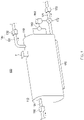
- FIG. 1 is a perspective view exemplarily illustrating a post-processing apparatus according to an embodiment of the present invention
- FIG. 2 is a cross-sectional view illustrating a concept of the post-processing apparatus according to the embodiment of the present invention.
- a post-processing apparatus 100 includes a receiving tank 110 having a receiving part 111 into which latex L is introduced, an ultrasonic wave generating device 120 configured to generate ultrasonic waves to the latex L, a pressure reducing part 130 configured to reduce a pressure of the receiving part 111 of the receiving tank 110, and a partition part 140 provided in the receiving part 111 of the receiving tank 110 and including a plurality of partitions disposed in a direction from an inlet port 112 toward a discharge port 113 of the receiving tank 110.
- the post-processing apparatus 100 may further include a foam breaker part F configured to remove foam generated by a flow of the latex, temperature adjusting parts 150 configured to adjust a temperature of the latex L, a level indicator 160 configured to measure a height level of the latex L, and a control part 180.
- the post-processing apparatus 100 may further include a latex L discharge valve 172 disposed at a side of the discharge port 113 of the receiving tank 110, a discharge line 171 connected to the discharge valve 172, and a discharge pump 173 provided in the discharge line 171.
- the post-processing apparatus 100 is the post-processing apparatus 100 that post-processes the latex L and separates and removes unreacted monomer.
- the latex L may be vinyl chloride-based copolymer latex L.
- the vinyl chloride-based copolymer may be polyvinyl chloride.
- the receiving tank 110 may have therein the receiving part 111 and have an inlet port 112 through which the latex L is introduced into the receiving part 111 and a discharge port 113 through which the latex L is discharged.
- the inlet port 112 may be provided at one side of the receiving tank 110, and the discharge port 113 may be provided at the other side of the receiving tank 110.
- the inlet port 112 may be provided at an upper lateral side of the receiving tank 110, and the discharge port 113 may be provided at a lower lateral side of the receiving tank 110.
- a volume of the receiving tank 110 may be 15 m 3 .
- the ultrasonic wave generating device 120 may generate the ultrasonic waves to the latex L accommodated in the receiving tank 110 and separate the unreacted monomer from the latex L. Therefore, it is possible to improve efficiency in removing the unreacted (residual) monomer.
- the ultrasonic wave generating device 120 may be provided at a lower side of the receiving tank 110 and may generate the ultrasonic waves to the latex L accommodated in the receiving tank 110.
- the ultrasonic waves when the ultrasonic waves are generated by the ultrasonic wave generating device 120, the ultrasonic waves propagate through a solution (latex), and cavitation occurs, such that fine low-pressure cavities are generated.
- the cavities are created and eliminated repeatedly within a very short time, and the number of cavities, the size of the cavities, and the momentum of the cavities are changed depending on frequencies of the generated ultrasonic waves, a temperature and a pressure of the solution, and the like.
- the cavities are accompanied by a rapid change in pressure while being generated and eliminated, and the residual unreacted monomer may be separated from the polymer (latex) by the cavities which are created and eliminated in the vicinity of a stripping target.
- the ultrasonic wave generating device 120 may generate the ultrasonic wave with a frequency of 75 to 1,500 kHz, for example. In this case, specifically, the ultrasonic wave generating device 120 may generate the ultrasonic wave with a frequency of 100 to 1,000 kHz, for example. In this case, when the ultrasonic wave generating device 120 generates the ultrasonic wave with a frequency of 100 kHz or more, it is possible to significantly improve efficiency in removing the unreacted monomer.
- the pressure reducing part 130 may discharge the unreacted monomer to the outside of the receiving tank 110 by reducing a pressure of the receiving part 111 of the receiving tank 110.
- the pressure reducing part 130 may include a pressure reducing line 131 connected to an upper side of the receiving tank 110, and a vacuum pump 132 provided in the pressure reducing line 131.
- the vacuum pump 132 of the pressure reducing part 130 may reduce the pressure of the receiving part 111 of the receiving tank 110 and thus remove and discharge the unreacted monomer, which is evaporated and separated from the latex L by the ultrasonic wave generating device 120, to the outside of the receiving tank 110 through the pressure reducing line 131.
- the pressure of the receiving part 111 of the receiving tank 110 when the pressure of the receiving part 111 of the receiving tank 110 is reduced by applying a vacuum pressure to the receiving part 111 through the pressure reducing line 131 by the vacuum pump 132, the evaporated, separated unreacted monomer positioned in the receiving part 111 of the receiving tank 110 may be easily discharged.
- the pressure of the receiving part 111 of the receiving tank 110 is reduced by the pressure reducing part 130, a boiling point of a volatile unreacted monomer is decreased, such that the volatile unreacted monomer may be more easily separated even without a separate carrier gas.
- the partition part 140 may be provided in the receiving part 111 of the receiving tank 110 and may include the plurality of partitions disposed in the direction from the inlet port 112 toward the discharge port 113 of the receiving tank 110.
- the latex L accommodated in the receiving part 111 may move along upper and lower sides of the plurality of partitions.
- the partition part 140 may include lower partitions 141 fixed to a bottom surface 114 of the receiving tank 110, and upper partitions 142 positioned to be spaced apart upward from the bottom surface 114 of the receiving tank 110 at a predetermined interval.
- the latex L accommodated in the receiving part 111 may move along upper sides of the lower partitions 141 and lower sides of the upper partitions 142.
- each of the lower partition 141 and the upper partition 142 may be provided in the form of a plate, and two opposite portions of each of the lower partition 141 and the upper partition 142 may be fixed to inner walls of two opposite sides of the receiving tank 110.
- the lower partitions 141 and the upper partition 142 may be alternately disposed in the direction from the inlet port 112 toward the discharge port 113 of the receiving tank 110.
- a surface area of the latex L may be increased as the latex L moves along the upper and lower sides of the lower partitions 141 and the upper partitions 142 disposed in the receiving part 111 of the receiving tank 110. That is, a contact area may be increased when the unreacted monomer is subjected to stripping by being sucked through the pressure reducing line 131 by the vacuum pressure applied by the pressure reducing part 130. Therefore, it is possible to significantly improve efficiency in removing the unreacted monomer.
- the latex L positioned the upper side is directly affected by the vacuum pressure of the pressure reducing part 130 positioned at the upper side of the receiving tank 110 and a portion of the latex L positioned at the lower side is relatively less affected by the vacuum pressure when the latex L is introduced into the inlet port 112 and then discharged through the discharge port 113.
- the latex L may be entirely and uniformly affected by the vacuum pressure.
- the portion of the latex L positioned at the lower side is greatly affected by the ultrasonic waves from the ultrasonic wave generator positioned at the lower side of the receiving tank 110 when the latex L is introduced into the inlet port 112 and then discharged through the discharge port 113, but the portion of the latex L positioned at the upper side is relatively less affected by the ultrasonic waves.
- the latex L may be entirely and uniformly affected by the vacuum pressure.
- the temperature adjusting parts 150 may be positioned in the receiving part 111 of the receiving tank 110 and may adjust a temperature of the latex L accommodated in the receiving part 111. Therefore, it is possible to improve efficiency in removing the unreacted (residual) monomer.
- the temperature adjusting parts 150 may be disposed between the lower partitions 141 and the upper partitions 142 in the movement direction of the latex L. In this case, the temperature adjusting parts 150 may be disposed at front and rear sides of each of the lower partition 141 and the upper partition 142 in the movement direction of the latex L, respectively.
- the temperature adjusting part 150 may be configured as a heater.
- the temperature adjusting part 150 may maintain a temperature of the latex L accommodated in the receiving part 111 as 73 to 87 °C, for example. In this case, specifically, the temperature adjusting part 150 may maintain the temperature of the latex L accommodated in the receiving part 111 as 75 to 85°C, for example. In this case, when the temperature adjusting part 150 maintains the temperature of the latex L accommodated in the receiving part 111 as 75°C or more, the efficiency in removing the unreacted monomer may be significantly improved.
- the foam breaker part F may be positioned at the upper side of the receiving tank 110 and may spray a foam removing substance to remove foam generated by the flow of the latex L in the receiving part 111.
- a substance such as a natural-fat-oil antifoaming agent, a polyether-based antifoaming agent, a high-grade aliphatic alcohol-based antifoaming agent, a silicon-based antifoaming agent, a paraffin-based antifoaming agent, or a mineral oil-based antifoaming agent, which is applied as an antifoaming agent, may be applied without limitation.
- the chemical substance, which is the foam removing substance may include aliphatic alcohol having a carbon number of 8 to 19. More specifically, the chemical substance may be at least one of aliphatic alcohol having a carbon number of 8 to 10, aliphatic alcohol having a carbon number of 12 to 18, and aliphatic alcohol having a carbon number of 16 to 18.
- the discharge valve 172 may be provided at the side of the discharge port 113 of the receiving tank 110 and adjust the discharge of the latex L. In this case, a residence time of the latex L in the receiving tank 110 may be adjusted by operating the discharge valve 172. In this case, the discharge valve 172 may be positioned at the lower lateral side of the receiving tank 110.
- the discharge line 171 may be connected to the discharge valve 172, and the discharge pump 173 may be provided in the discharge line 171.
- the discharge pump 173 may operate to discharge the latex L, which is accommodated in the receiving part 111 of the receiving tank 110, to the outside of the receiving tank 110 through the discharge line 171.
- the discharge pump 173 may be provided in the discharge line 171 so as to be farther from the receiving tank 110 than the discharge valve 172. Therefore, the discharge valve 172 may adjust the discharge amount of latex L even though the discharge pump 173 operates.
- the level indicator 160 may measure a height level of the latex L. In this case, it is possible to adjust the residence time of the latex L in the receiving tank 110 by adjusting the discharge valve 172 based on the height level of the latex L measured by the level indicator 160.
- the level indicator 160 may include a liquid level measuring sensor 161 provided at the lateral side of the receiving part 111 of the receiving tank 110 and configured to measure a height (level) of the accommodated liquid. Therefore, the level indicator 160 may measure the height level of the latex L accommodated in the receiving part 111.
- the control part 180 may adjust an opening degree of the discharge valve 172 by being supplied with a measured level value of the latex L from the level indicator 160. In this case, when the control part 180 determines that the measured level value of the latex is smaller than a value stored in a memory (not illustrated), the control part 180 increases the discharge amount of the latex L by further opening the discharge valve 172. When the control part 180 determines that the measured level value of the latex is larger than the value stored in the memory, the control part 180 may adjust the residence time of the latex L in the receiving tank 110 by decreasing the discharge amount of latex L by further closing the discharge valve 172.
- control part 180 may maintain the residence time of the latex L in the receiving tank 110 as 13 to 32 minutes, for example. In this case, specifically, the control part 180 may maintain the residence time of the latex L in the receiving tank 110 as 15 to 25 minutes, for example.
- the post-processing apparatus 100 may further include an inlet line 191 connected to the inlet port 112 of the receiving tank 110, and an inlet pump 192 provided in the inlet line 191.
- the inlet pump 192 may operate to introduce the latex L into the receiving part 111 of the receiving tank 110 through the inlet line 191.
- the post-processing apparatus 100 may remove the unreacted residual monomer with high efficiency without impairing thermal stability of the latex L by applying the ultrasonic waves to the latex L by the ultrasonic wave generating device 120, increasing the contact area of the latex L by the partition part 140, reducing the pressure by the pressure reducing part 130, and maintaining the appropriate temperature of the latex L by the temperature adjusting part 150.
- the post-processing apparatus 100 may reduce the unreacted (residual) monomer content of the latex L to 10 ppm or less and may satisfy a condition in which the color has a white index (WI) of 90 or more.
- WI white index
- Latex was inputted into the inlet port of the receiving tank having therein the receiving part and having a volume of 15 m 3 , the inputted latex moved along the upper and lower sides of the partition part including the plurality of upper partitions and the plurality of lower partitions disposed alternately, and the latex flowed toward the discharge port of the receiving tank.
- a temperature of the latex was maintained as 80°C by the temperature adjusting parts positioned between the upper partitions and the lower partitions, and the ultrasonic wave generating device positioned at the lower side of the receiving tank generated ultrasonic waves with a frequency of 300 kHz.
- foam was removed by spraying the foam removing substance by the foam breaker part during the flow of the latex, and the residual unreacted monomer generated at this time was reduced in pressure and removed by the pressure reducing part.
- the level indicator measured a height level of the latex
- the control part adjusted the latex discharge valve, such that the residence time of the latex in the receiving tank was maintained as 20 minutes.
- Example 2 A process identical to the process of Example 1 was performed except that the temperature of the latex was maintained as 75°C by the temperature adjusting parts.
- Example 2 A process identical to the process of Example 1 was performed except that the temperature of the latex was maintained as 85°C by the temperature adjusting parts.
- a process identical to the process of Example 1 was performed except that the residence time of the latex in the receiving tank was maintained as 15 minutes by adjusting the discharge valve by the control part.
- a process identical to the process of Example 1 was performed except that the residence time of the latex in the receiving tank was maintained as 25 minutes by adjusting the discharge valve by the control part.
- a process identical to the process of Example 1 was performed except that the ultrasonic wave with a frequency of 100 kHz was generated by the ultrasonic wave generating device.
- Latex was inputted into a tank having a volume of 15m 3 and agitated at 35 rpm, a temperature of a jacket was raised to 80°C, and stripping was performed for 20 minutes under a reduced pressure.
- Latex was inputted into a tank having a volume of 15m 3 and agitated at 70 rpm, a temperature of a jacket was raised to 80°C, and stripping was performed for 20 minutes under a reduced pressure.
- Latex was inputted into a tank having a volume of 15m 3 and agitated at 35 rpm, a temperature of a jacket was raised to 90°C, and stripping was performed for 20 minutes under a reduced pressure.
- Latex was inputted into a tank having a volume of 15m 3 and agitated at 35 rpm, a temperature of a jacket was raised to 90°C, and stripping was performed for 40 minutes under a reduced pressure.
- Latex was inputted into a tank having a volume of 15m3 and agitated at 35 rpm, steam having a temperature of 120°C was injected through a lower portion of the tank, and stripping was performed for 20 minutes under a reduced pressure.
- Example 2 A process identical to the process of Example 1 was performed except that no ultrasonic wave was generated by the ultrasonic wave generating device.
- a process identical to the process of Example 1 was performed except that the ultrasonic wave with a frequency of 50 kHz was generated by the ultrasonic wave generating device and stripping was performed.
- a process identical to the process of Example 1 was performed except that the temperature of the latex was set to 70°C and stripping was performed.
- a process identical to the process of Example 1 was performed except that the temperature of the latex was set to 90°C and stripping was performed.
- a process identical to the process of Example 1 was performed except that the partition part was removed and stripping was performed.
- a process identical to the process of Example 1 was performed except that the residence time of the latex was set to 10 minutes and stripping was performed.
- a process identical to the process of Example 1 was performed except that the residence time of the latex was set to 30 minutes and stripping was performed.
- VCM components which are obtained in a condition of the latex of 2g, 90°C, 20 minutes, and 20 mL vial, were analyzed using HS-GC/SIM mode(m/z62,62) which is headspace analysis equipment.
- Table 1 shows the residual (unreacted) monomer contents (ppm) and the latex colors (W.I.) of Examples 1 to 6, and Table 2 shows the residual monomer contents (ppm) and the latex colors (W.I.) of Comparative Examples 1 to 13.
- Table 2 shows the residual monomer contents (ppm) and the latex colors (W.I.) of Comparative Examples 1 to 13.
- Table 2 shows the values, which indicate the low efficiency in removing the residual monomer and the deterioration in latex color, are shown with underlines.
- Examples 1 to 6 have the high efficiency in removing the residual monomers because the residual monomer contents (ppm) of Examples 1 to 6 are lower than 9.3 (ppm), but Comparative Examples 1 to 4, 6 to 9, 11, and 12 have the low efficiency in removing the residual monomer because the residual monomer contents (ppm) of Comparative Examples 1 to 4 are 35 (ppm) or more and the residual monomer contents (ppm) of Comparative Examples 6 to 9, 11, and 12 are 11.3 (ppm) or more.
- Examples 1 to 6 have excellent thermal stability because the latex colors (W.I.) of Examples 1 to 6 are 90 or more, but Comparative Examples 5, 10, and 13 are lower in thermal stability than Examples 1 to 6 because the latex colors (W.I.) of Comparative Examples 5, 10, and 13 are 88.4 or less.
Landscapes
- Chemical & Material Sciences (AREA)
- Chemical Kinetics & Catalysis (AREA)
- Organic Chemistry (AREA)
- Health & Medical Sciences (AREA)
- Medicinal Chemistry (AREA)
- Polymers & Plastics (AREA)
- Toxicology (AREA)
- General Health & Medical Sciences (AREA)
- Dispersion Chemistry (AREA)
- Addition Polymer Or Copolymer, Post-Treatments, Or Chemical Modifications (AREA)
Abstract
Description
- This application claims priority to and the benefit of
Korean Patent Application No. 10-2020-0050155 filed in the Korean Intellectual Property Office on April 24, 2020 - The present invention relates to a post-processing apparatus.
- During a process of polymerizing PVC using vinyl chloride monomers, a rate of conversion of the monomers decreases as a polymerization conversion ratio becomes closer to 100%. Therefore, when the conversion ratio reaches a predetermined conversion ratio, the polymerization is ended, unreacted monomers are recovered, and then polymers are obtained. Legal regulations on the number of unreacted monomers contained in a product and an environmental problem of unreacted monomers discharged during a drying process are strengthened. For this reason, the unreacted monomers need to be managed and minimized.
- In general, there have been used a method of recovering unreacted monomers from polymers by raising a temperature and/or reducing a pressure in a reactor after polymerization and a method of recovering unreacted monomers by conveying completely polymerized polymers to another tank under a raised-temperature and/or reduced-pressure condition. However, these methods have poor efficiency in recovering the unreacted monomers. In addition, a method of recovering unreacted monomers using steam has a problem in that thermal stability of latex deteriorates due to a high temperature, which adversely affects physical properties of a final product.
- (Patent Document 1)
Korean Patent Laid-Open No. 10-2001-0050323 - An object of the present invention is to provide a post-processing apparatus capable of removing an unreacted monomer with high efficiency without impairing thermal stability of latex.
- A post-processing apparatus according to an embodiment of the present invention is configured to post-process latex and includes: a receiving tank having therein a receiving part and having an inlet port through which the latex is introduced into the receiving part and a discharge port through which the latex is discharged; an ultrasonic wave generating device configured to generate ultrasonic waves to the latex accommodated in the receiving tank; a pressure reducing part configured to reduce a pressure of the receiving part of the receiving tank to discharge an unreacted monomer to the outside of the receiving tank; and a partition part provided in the receiving part of the receiving tank and including a plurality of partitions disposed in a direction from the inlet port toward the discharge port of the receiving tank, in which the latex accommodated in the receiving part moves along upper and lower sides of the plurality of partitions.
- According to the present invention, it is possible to remove the unreacted residual monomer with high efficiency without impairing thermal stability of the latex by applying the ultrasonic waves to the latex by the ultrasonic wave generating device, increasing the contact area of the latex by the partition part, and reducing the pressure by the pressure reducing part.
- In addition, it is possible to improve the efficiency in removing the unreacted monomer and prevent deterioration in color of the latex by adjusting the residence time of the latex in the receiving tank by controlling the discharge valve for discharging the latex by the control part based on the measured value of the height level of the latex.
-
-
FIG. 1 is a perspective view exemplarily illustrating a post-processing apparatus according to an embodiment of the present invention. -
FIG. 2 is a cross-sectional view illustrating a concept of the post-processing apparatus according to the embodiment of the present invention. - Other objects, particular advantages, and novel features of the present invention will be more clearly understood from the following detailed description and the exemplary embodiments with reference to the accompanying drawings. In giving reference numerals to constituent elements of the respective drawings in the present specification, it should be noted that the same constituent elements will be designated by the same reference numerals, if possible, even though the constituent elements are illustrated in different drawings. In addition, the present invention may be implemented in various different ways, and is not limited to the embodiments described herein. Further, in the description of the present invention, the specific descriptions of well-known related technologies will be omitted when it is determined that the specific descriptions may unnecessarily obscure the subject matter of the present invention.
-
FIG. 1 is a perspective view exemplarily illustrating a post-processing apparatus according to an embodiment of the present invention, andFIG. 2 is a cross-sectional view illustrating a concept of the post-processing apparatus according to the embodiment of the present invention. - Referring to
FIGS. 1 and2 , apost-processing apparatus 100 according to the embodiment of the present invention includes a receivingtank 110 having a receivingpart 111 into which latex L is introduced, an ultrasonicwave generating device 120 configured to generate ultrasonic waves to the latex L, apressure reducing part 130 configured to reduce a pressure of thereceiving part 111 of thereceiving tank 110, and apartition part 140 provided in thereceiving part 111 of thereceiving tank 110 and including a plurality of partitions disposed in a direction from aninlet port 112 toward adischarge port 113 of thereceiving tank 110. - In addition, the
post-processing apparatus 100 according to the embodiment of the present invention may further include a foam breaker part F configured to remove foam generated by a flow of the latex,temperature adjusting parts 150 configured to adjust a temperature of the latex L, alevel indicator 160 configured to measure a height level of the latex L, and acontrol part 180. - Further, the
post-processing apparatus 100 according to the embodiment of the present invention may further include a latexL discharge valve 172 disposed at a side of thedischarge port 113 of thereceiving tank 110, adischarge line 171 connected to thedischarge valve 172, and adischarge pump 173 provided in thedischarge line 171. - In more detail, the
post-processing apparatus 100 according to the embodiment of the present invention is thepost-processing apparatus 100 that post-processes the latex L and separates and removes unreacted monomer. - In this case, the latex L may be vinyl chloride-based copolymer latex L. In this case, the vinyl chloride-based copolymer may be polyvinyl chloride.
- The
receiving tank 110 may have therein thereceiving part 111 and have aninlet port 112 through which the latex L is introduced into thereceiving part 111 and adischarge port 113 through which the latex L is discharged. - The
inlet port 112 may be provided at one side of thereceiving tank 110, and thedischarge port 113 may be provided at the other side of thereceiving tank 110. In this case, theinlet port 112 may be provided at an upper lateral side of thereceiving tank 110, and thedischarge port 113 may be provided at a lower lateral side of thereceiving tank 110. - In addition, a volume of the
receiving tank 110 may be 15 m3. - The ultrasonic
wave generating device 120 may generate the ultrasonic waves to the latex L accommodated in thereceiving tank 110 and separate the unreacted monomer from the latex L. Therefore, it is possible to improve efficiency in removing the unreacted (residual) monomer. - In addition, the ultrasonic
wave generating device 120 may be provided at a lower side of thereceiving tank 110 and may generate the ultrasonic waves to the latex L accommodated in thereceiving tank 110. In this case, when the ultrasonic waves are generated by the ultrasonicwave generating device 120, the ultrasonic waves propagate through a solution (latex), and cavitation occurs, such that fine low-pressure cavities are generated. The cavities are created and eliminated repeatedly within a very short time, and the number of cavities, the size of the cavities, and the momentum of the cavities are changed depending on frequencies of the generated ultrasonic waves, a temperature and a pressure of the solution, and the like. The cavities are accompanied by a rapid change in pressure while being generated and eliminated, and the residual unreacted monomer may be separated from the polymer (latex) by the cavities which are created and eliminated in the vicinity of a stripping target. - Further, the ultrasonic
wave generating device 120 may generate the ultrasonic wave with a frequency of 75 to 1,500 kHz, for example. In this case, specifically, the ultrasonicwave generating device 120 may generate the ultrasonic wave with a frequency of 100 to 1,000 kHz, for example. In this case, when the ultrasonicwave generating device 120 generates the ultrasonic wave with a frequency of 100 kHz or more, it is possible to significantly improve efficiency in removing the unreacted monomer. - The
pressure reducing part 130 may discharge the unreacted monomer to the outside of the receivingtank 110 by reducing a pressure of thereceiving part 111 of thereceiving tank 110. - In addition, the
pressure reducing part 130 may include apressure reducing line 131 connected to an upper side of thereceiving tank 110, and avacuum pump 132 provided in thepressure reducing line 131. - Further, the
vacuum pump 132 of thepressure reducing part 130 may reduce the pressure of thereceiving part 111 of the receivingtank 110 and thus remove and discharge the unreacted monomer, which is evaporated and separated from the latex L by the ultrasonicwave generating device 120, to the outside of the receivingtank 110 through thepressure reducing line 131. - In this case, when the pressure of the receiving
part 111 of the receivingtank 110 is reduced by applying a vacuum pressure to the receivingpart 111 through thepressure reducing line 131 by thevacuum pump 132, the evaporated, separated unreacted monomer positioned in thereceiving part 111 of thereceiving tank 110 may be easily discharged. In this case, when the pressure of the receivingpart 111 of thereceiving tank 110 is reduced by thepressure reducing part 130, a boiling point of a volatile unreacted monomer is decreased, such that the volatile unreacted monomer may be more easily separated even without a separate carrier gas. - Meanwhile, the
vacuum pump 132 of thepressure reducing part 130 may apply the vacuum pressure of -0.5 to -0.7 kg/cm2. - The
partition part 140 may be provided in thereceiving part 111 of thereceiving tank 110 and may include the plurality of partitions disposed in the direction from theinlet port 112 toward thedischarge port 113 of thereceiving tank 110. In this case, the latex L accommodated in thereceiving part 111 may move along upper and lower sides of the plurality of partitions. - In addition, the
partition part 140 may includelower partitions 141 fixed to abottom surface 114 of thereceiving tank 110, andupper partitions 142 positioned to be spaced apart upward from thebottom surface 114 of thereceiving tank 110 at a predetermined interval. In this case, the latex L accommodated in thereceiving part 111 may move along upper sides of thelower partitions 141 and lower sides of theupper partitions 142. In this case, each of thelower partition 141 and theupper partition 142 may be provided in the form of a plate, and two opposite portions of each of thelower partition 141 and theupper partition 142 may be fixed to inner walls of two opposite sides of thereceiving tank 110. - Meanwhile, the
lower partitions 141 and theupper partition 142 may be alternately disposed in the direction from theinlet port 112 toward thedischarge port 113 of thereceiving tank 110. - Therefore, a surface area of the latex L may be increased as the latex L moves along the upper and lower sides of the
lower partitions 141 and theupper partitions 142 disposed in thereceiving part 111 of thereceiving tank 110. That is, a contact area may be increased when the unreacted monomer is subjected to stripping by being sucked through thepressure reducing line 131 by the vacuum pressure applied by thepressure reducing part 130. Therefore, it is possible to significantly improve efficiency in removing the unreacted monomer. - Further, if there is no
partition part 140, only a portion of the latex L positioned the upper side is directly affected by the vacuum pressure of thepressure reducing part 130 positioned at the upper side of thereceiving tank 110 and a portion of the latex L positioned at the lower side is relatively less affected by the vacuum pressure when the latex L is introduced into theinlet port 112 and then discharged through thedischarge port 113. However, when the latex L moves along the upper and lower sides, the latex L may be entirely and uniformly affected by the vacuum pressure. - In addition, if there is no
partition part 140, the portion of the latex L positioned at the lower side is greatly affected by the ultrasonic waves from the ultrasonic wave generator positioned at the lower side of thereceiving tank 110 when the latex L is introduced into theinlet port 112 and then discharged through thedischarge port 113, but the portion of the latex L positioned at the upper side is relatively less affected by the ultrasonic waves. However, when the latex L moves along the upper and lower sides of thepartition part 140, the latex L may be entirely and uniformly affected by the vacuum pressure. - The
temperature adjusting parts 150 may be positioned in the receivingpart 111 of the receivingtank 110 and may adjust a temperature of the latex L accommodated in the receivingpart 111. Therefore, it is possible to improve efficiency in removing the unreacted (residual) monomer. - In addition, the
temperature adjusting parts 150 may be disposed between thelower partitions 141 and theupper partitions 142 in the movement direction of the latex L. In this case, thetemperature adjusting parts 150 may be disposed at front and rear sides of each of thelower partition 141 and theupper partition 142 in the movement direction of the latex L, respectively. - Further, the
temperature adjusting part 150 may be configured as a heater. - Further, the
temperature adjusting part 150 may maintain a temperature of the latex L accommodated in the receivingpart 111 as 73 to 87 °C, for example. In this case, specifically, thetemperature adjusting part 150 may maintain the temperature of the latex L accommodated in the receivingpart 111 as 75 to 85°C, for example. In this case, when thetemperature adjusting part 150 maintains the temperature of the latex L accommodated in the receivingpart 111 as 75°C or more, the efficiency in removing the unreacted monomer may be significantly improved. - The foam breaker part F may be positioned at the upper side of the receiving
tank 110 and may spray a foam removing substance to remove foam generated by the flow of the latex L in the receivingpart 111. - Therefore, bubbles generated by the flow of the latex L are removed, such that the efficiency in removing the unreacted monomer from the latex L may be improved.
- In this case, as a chemical substance, which is the foam removing substance, a substance, such as a natural-fat-oil antifoaming agent, a polyether-based antifoaming agent, a high-grade aliphatic alcohol-based antifoaming agent, a silicon-based antifoaming agent, a paraffin-based antifoaming agent, or a mineral oil-based antifoaming agent, which is applied as an antifoaming agent, may be applied without limitation. In this case, specifically, the chemical substance, which is the foam removing substance, may include aliphatic alcohol having a carbon number of 8 to 19. More specifically, the chemical substance may be at least one of aliphatic alcohol having a carbon number of 8 to 10, aliphatic alcohol having a carbon number of 12 to 18, and aliphatic alcohol having a carbon number of 16 to 18.
- The
discharge valve 172 may be provided at the side of thedischarge port 113 of the receivingtank 110 and adjust the discharge of the latex L. In this case, a residence time of the latex L in the receivingtank 110 may be adjusted by operating thedischarge valve 172. In this case, thedischarge valve 172 may be positioned at the lower lateral side of the receivingtank 110. - The
discharge line 171 may be connected to thedischarge valve 172, and thedischarge pump 173 may be provided in thedischarge line 171. In this case, thedischarge pump 173 may operate to discharge the latex L, which is accommodated in the receivingpart 111 of the receivingtank 110, to the outside of the receivingtank 110 through thedischarge line 171. In this case, thedischarge pump 173 may be provided in thedischarge line 171 so as to be farther from the receivingtank 110 than thedischarge valve 172. Therefore, thedischarge valve 172 may adjust the discharge amount of latex L even though thedischarge pump 173 operates. - The
level indicator 160 may measure a height level of the latex L. In this case, it is possible to adjust the residence time of the latex L in the receivingtank 110 by adjusting thedischarge valve 172 based on the height level of the latex L measured by thelevel indicator 160. - In this case, the
level indicator 160 may include a liquidlevel measuring sensor 161 provided at the lateral side of the receivingpart 111 of the receivingtank 110 and configured to measure a height (level) of the accommodated liquid. Therefore, thelevel indicator 160 may measure the height level of the latex L accommodated in the receivingpart 111. - The
control part 180 may adjust an opening degree of thedischarge valve 172 by being supplied with a measured level value of the latex L from thelevel indicator 160. In this case, when thecontrol part 180 determines that the measured level value of the latex is smaller than a value stored in a memory (not illustrated), thecontrol part 180 increases the discharge amount of the latex L by further opening thedischarge valve 172. When thecontrol part 180 determines that the measured level value of the latex is larger than the value stored in the memory, thecontrol part 180 may adjust the residence time of the latex L in the receivingtank 110 by decreasing the discharge amount of latex L by further closing thedischarge valve 172. - In addition, the
control part 180 may maintain the residence time of the latex L in the receivingtank 110 as 13 to 32 minutes, for example. In this case, specifically, thecontrol part 180 may maintain the residence time of the latex L in the receivingtank 110 as 15 to 25 minutes, for example. - In this case, it is possible to significantly improve the efficiency in removing the unreacted monomer by maintaining the residence time of the latex L in the receiving
tank 110 as 15 minutes or more by thecontrol part 180, and it is possible to effectively prevent deterioration in color of the latex L by maintaining the residence time as 25 minutes or less. - Meanwhile, the
post-processing apparatus 100 according to the embodiment of the present invention may further include aninlet line 191 connected to theinlet port 112 of the receivingtank 110, and aninlet pump 192 provided in theinlet line 191. - In this case, the
inlet pump 192 may operate to introduce the latex L into the receivingpart 111 of the receivingtank 110 through theinlet line 191. - The
post-processing apparatus 100 according to the embodiment of the present invention configured as described above may remove the unreacted residual monomer with high efficiency without impairing thermal stability of the latex L by applying the ultrasonic waves to the latex L by the ultrasonicwave generating device 120, increasing the contact area of the latex L by thepartition part 140, reducing the pressure by thepressure reducing part 130, and maintaining the appropriate temperature of the latex L by thetemperature adjusting part 150. - In addition, it is possible to improve the efficiency in removing the unreacted monomer and prevent deterioration in color of the latex L by measuring the height level of the latex L by the
level indicator 160, controlling the opening degree of thedischarge valve 172 for discharging the latex L by thecontrol part 180 based on the measured value, and thus adjusting the residence time of the latex L in the receivingtank 110. - As a result, the
post-processing apparatus 100 according to the embodiment of the present invention may reduce the unreacted (residual) monomer content of the latex L to 10 ppm or less and may satisfy a condition in which the color has a white index (WI) of 90 or more. - Latex was inputted into the inlet port of the receiving tank having therein the receiving part and having a volume of 15 m3, the inputted latex moved along the upper and lower sides of the partition part including the plurality of upper partitions and the plurality of lower partitions disposed alternately, and the latex flowed toward the discharge port of the receiving tank.
- In this case, a temperature of the latex was maintained as 80°C by the temperature adjusting parts positioned between the upper partitions and the lower partitions, and the ultrasonic wave generating device positioned at the lower side of the receiving tank generated ultrasonic waves with a frequency of 300 kHz.
- In addition, foam was removed by spraying the foam removing substance by the foam breaker part during the flow of the latex, and the residual unreacted monomer generated at this time was reduced in pressure and removed by the pressure reducing part.
- Further, the level indicator measured a height level of the latex, and the control part adjusted the latex discharge valve, such that the residence time of the latex in the receiving tank was maintained as 20 minutes.
- A process identical to the process of Example 1 was performed except that the temperature of the latex was maintained as 75°C by the temperature adjusting parts.
- A process identical to the process of Example 1 was performed except that the temperature of the latex was maintained as 85°C by the temperature adjusting parts.
- A process identical to the process of Example 1 was performed except that the residence time of the latex in the receiving tank was maintained as 15 minutes by adjusting the discharge valve by the control part.
- A process identical to the process of Example 1 was performed except that the residence time of the latex in the receiving tank was maintained as 25 minutes by adjusting the discharge valve by the control part.
- A process identical to the process of Example 1 was performed except that the ultrasonic wave with a frequency of 100 kHz was generated by the ultrasonic wave generating device.
- Latex was inputted into a tank having a volume of 15m3 and agitated at 35 rpm, a temperature of a jacket was raised to 80°C, and stripping was performed for 20 minutes under a reduced pressure.
- Latex was inputted into a tank having a volume of 15m3 and agitated at 70 rpm, a temperature of a jacket was raised to 80°C, and stripping was performed for 20 minutes under a reduced pressure.
- Latex was inputted into a tank having a volume of 15m3 and agitated at 35 rpm, a temperature of a jacket was raised to 90°C, and stripping was performed for 20 minutes under a reduced pressure.
- Latex was inputted into a tank having a volume of 15m3 and agitated at 35 rpm, a temperature of a jacket was raised to 90°C, and stripping was performed for 40 minutes under a reduced pressure.
- Latex was inputted into a tank having a volume of 15m3 and agitated at 35 rpm, steam having a temperature of 120°C was injected through a lower portion of the tank, and stripping was performed for 20 minutes under a reduced pressure.
- A process identical to the process of Example 1 was performed except that no ultrasonic wave was generated by the ultrasonic wave generating device.
- A process identical to the process of Example 1 was performed except that the ultrasonic wave with a frequency of 50 kHz was generated by the ultrasonic wave generating device and stripping was performed.
- A process identical to the process of Example 1 was performed except that no temperature adjusting part was used. In this case, a temperature of the latex was 40°C.
- A process identical to the process of Example 1 was performed except that the temperature of the latex was set to 70°C and stripping was performed.
- A process identical to the process of Example 1 was performed except that the temperature of the latex was set to 90°C and stripping was performed.
- A process identical to the process of Example 1 was performed except that the partition part was removed and stripping was performed.
- A process identical to the process of Example 1 was performed except that the residence time of the latex was set to 10 minutes and stripping was performed.
- A process identical to the process of Example 1 was performed except that the residence time of the latex was set to 30 minutes and stripping was performed.
- In order to measure the residual monomer content, VCM components, which are obtained in a condition of the latex of 2g, 90°C, 20 minutes, and 20 mL vial, were analyzed using HS-GC/SIM mode(m/z62,62) which is headspace analysis equipment.
- In order to measure a latex color, the latex, on which the stripping was completely performed, was inputted into a transparent PE bag, and thermal stability was evaluated by measuring a white index (W.I.) using an L,a,b method using an L,a,b color system.
- The residual monomer contents and the latex colors measured by the experiments of Experimental Example 1 are shown in Tables 1 and 2.
[Table 1] Examples 1 2 3 4 5 6 Residual Monomer Content (ppm) 8.2 8.9 7.8 9.1 8.0 9.3 Latex Color (W.I.) 90.3 90.7 91.1 91.2 90.2 90.4 [Table 2] Comparative Examples 1 2 3 4 5 6 7 8 9 10 11 12 13 Resid ual Mono mer Conte nt (ppm) 48.2 37.6 35.1 40.3 9.7 24.9 12.1 21.6 11.3 8.0 17.6 19.5 7.7 Latex Color (W.I.) 90.5 90.6 89.1 89.7 81.3 90.4 90.2 92.4 90.9 88.4 90.1 90.6 87.1 - Table 1 shows the residual (unreacted) monomer contents (ppm) and the latex colors (W.I.) of Examples 1 to 6, and Table 2 shows the residual monomer contents (ppm) and the latex colors (W.I.) of Comparative Examples 1 to 13. In this case, in Table 2, the values, which indicate the low efficiency in removing the residual monomer and the deterioration in latex color, are shown with underlines.
- Referring to Tables 1 and 2, it can be seen that Examples 1 to 6 have the high efficiency in removing the residual monomers because the residual monomer contents (ppm) of Examples 1 to 6 are lower than 9.3 (ppm), but Comparative Examples 1 to 4, 6 to 9, 11, and 12 have the low efficiency in removing the residual monomer because the residual monomer contents (ppm) of Comparative Examples 1 to 4 are 35 (ppm) or more and the residual monomer contents (ppm) of Comparative Examples 6 to 9, 11, and 12 are 11.3 (ppm) or more.
- In addition, referring to Tables 1 and 2, it can be seen that Examples 1 to 6 have excellent thermal stability because the latex colors (W.I.) of Examples 1 to 6 are 90 or more, but Comparative Examples 5, 10, and 13 are lower in thermal stability than Examples 1 to 6 because the latex colors (W.I.) of Comparative Examples 5, 10, and 13 are 88.4 or less.
- In more detail, referring to Tables 1 and 2, it can be seen that the residual monomer content is significantly as high as 35.1 (ppm) or more when the stripping is performed together with the agitation at a temperature raised by the jacket, like Comparative Examples 1 to 4. In this case, it can be seen that the efficiency in removing the residual monomer is poor even though the RPM is increased to 70 rpm like Comparative Example 2, the temperature is raised to 90°C like Comparative Example 3, or the operation is performed for a long time, i.e., 40 minutes like Comparative Example 4. Further, there is a problem in that a large amount of foam is generated due to latex properties when the stripping is performed together with the agitation at a temperature raised by the jacket, like Comparative Examples 1 to 4.
- It can be seen that in the case in which the steam is used like Comparative Example 5, the latex color is as poor as 81.3. In addition, in a case in which the steam is used like Comparative Example 5, there is a problem in that the latex is attached to a high-temperature portion and changed in color while adhering to the high-temperature portion.
- It can be seen that in a case in which no ultrasonic wave is used like Comparative Example 6, the residual monomer content is 24.9, and the efficiency in removing the residual monomer is significantly low.
- It can be seen that in a case in which the ultrasonic wave with a low frequency of 50 kHz is generated like Comparative Example 7, the residual monomer content is 12.1, and the efficiency in removing the residual monomer is low.
- It can be seen that in a case in which no temperature adjusting part is used like Comparative Example 8, the residual monomer content is 21.6, and the efficiency in removing the residual monomer is low.
- It can be seen that in a case in which the temperature of the latex is set to a low temperature of 70°C like Comparative Example 9, the residual monomer content is 11.3, and the efficiency in removing the residual monomer is low.
- It can be seen that in a case in which the temperature of the latex is set to a high temperature of 90°C like Comparative Example 10, the latex color is as poor as 88.4.
- It can be seen that in a case in which the partition part is removed like Comparative Example 11, the residual monomer content is 17.6, and the efficiency in removing the residual monomer is low.
- It can be seen that in a case in which the residence time of the latex is very as short as 10 minutes like Comparative Example 12, the residual monomer content is 19.5, and the efficiency in removing the residual monomer is low.
- It can be seen that in a case in which the residence time of the latex is very as long as 30 minutes like Comparative Example 13, the color of the latex is as poor as 87.1.
- As a result, it can be seen that Examples 1 to 6 have high efficiency in removing the residual monomer and excellent in thermal stability in comparison with Comparative Examples 1 to 13.
- While the present invention has been described with reference to the specific embodiments, the specific embodiments are only for specifically explaining the present invention, and the post-processing apparatus according to the present disclosure is not limited to the specific embodiments. The present invention may be variously carried out by those skilled in the art without departing from the technical spirit of the present invention.
- In addition, the specific protection scope of the present invention will be defined by the appended claims.
-
- 100: Post-processing apparatus
- 110: Receiving tank
- 111: Receiving part
- 112: Inlet port
- 113: Discharge port
- 114: Bottom surface
- 120: Ultrasonic wave generating device
- 130: Pressure reducing part
- 131: Pressure reducing line
- 132: Vacuum pump
- 140: Partition part
- 141: Lower partition
- 142: Upper partition
- 150: Temperature adjusting part
- 160: Level indicator
- 161: Liquid level measuring sensor
- 171: Discharge line
- 172: Discharge valve
- 173: Discharge pump
- 180: Control part
- 191: Inlet line
- 192: Inlet pump
- L: latex
- F: Foam breaker part
Claims (19)
- A post-processing apparatus configured to post-process latex, the post-processing apparatus comprising:a receiving tank having therein a receiving part and having an inlet port through which the latex is introduced into the receiving part and a discharge port through which the latex is discharged;an ultrasonic wave generating device configured to generate ultrasonic waves to the latex accommodated in the receiving tank;a pressure reducing part configured to reduce a pressure of the receiving part of the receiving tank to discharge an unreacted monomer to the outside of the receiving tank; anda partition part provided in the receiving part of the receiving tank and comprising a plurality of partitions disposed in a direction from the inlet port toward the discharge port of the receiving tank,wherein the latex accommodated in the receiving part moves along upper and lower sides of the plurality of partitions.
- The post-processing apparatus of claim 1, wherein the partition part comprises:lower partitions fixed to a bottom surface of the tank; andupper partitions positioned to be spaced apart upward from the bottom surface of the tank at a predetermined interval, andwherein the latex accommodated in the receiving part moves along upper sides of the lower partition and lower sides of the upper partition.
- The post-processing apparatus of claim 2, wherein the lower partitions and the upper partitions are disposed alternately in a direction from the inlet port toward the discharge port of the receiving tank.
- The post-processing apparatus of claim 1, wherein the pressure reducing part comprises:a pressure reducing line connected to an upper side of the receiving tank; anda vacuum pump provided in the pressure reducing line, andwherein the pressure reducing part reduces a pressure of the receiving part of the receiving tank by the vacuum pump and removes and discharges the unreacted monomer, which is evaporated and separated from the latex by the ultrasonic wave generating device, to the outside of the receiving tank through the pressure reducing line.
- The post-processing apparatus of claim 1, further comprising:
a foam breaker part positioned at an upper side of the receiving tank and configured to spray a foam removing substance to remove foam generated by a flow of the latex in the receiving part. - The post-processing apparatus of claim 1, wherein the latex is vinyl chloride-based copolymer latex.
- The post-processing apparatus of claim 1, wherein the ultrasonic wave generating device is provided at a lower side of the receiving tank and generates the ultrasonic waves to the latex accommodated in the receiving tank.
- The post-processing apparatus of claim 2, further comprising:
temperature adjusting parts positioned in the receiving part of the receiving tank and configured to adjust a temperature of the latex accommodated in the receiving part. - The post-processing apparatus of claim 8, wherein the temperature adjusting parts are disposed between the lower partitions and the upper partitions in a movement direction of the latex.
- The post-processing apparatus of claim 8, wherein the temperature adjusting part maintains a temperature of the latex accommodated in the receiving part as 73 to 87°C.
- The post-processing apparatus of claim 8, wherein the temperature adjusting part maintains a temperature of the latex accommodated in the receiving part as 75 to 85°C.
- The post-processing apparatus of claim 1, wherein the ultrasonic wave generating device generates the ultrasonic wave with 75 to 1,500 kHz.
- The post-processing apparatus of claim 1, wherein the ultrasonic wave generating device generates the ultrasonic wave with 100 to 1,000 kHz.
- The post-processing apparatus of claim 1, further comprising:a latex discharge valve provided at a side of the discharge port of the receiving tank,wherein the discharge valve is adjusted to adjust a residence time of the latex in the receiving tank.
- The post-processing apparatus of claim 14, further comprising:a level indicator configured to measure a height level of the latex,wherein the residence time of the latex in the receiving tank is adjusted by adjusting the discharge valve based on the height level of the latex measured by the level indicator.
- The post-processing apparatus of claim 15, further comprising:
a control part configured to adjust an opening degree of the discharge valve by being supplied with a measured value of the latex from the level indicator. - The post-processing apparatus of claim 16, wherein the control part maintains the residence time of the latex in the receiving tank as 13 to 32 minutes.
- The post-processing apparatus of claim 16, wherein the control part maintains the residence time of the latex in the receiving tank as 15 to 25 minutes.
- The post-processing apparatus of claim 14, further comprising:a discharge line connected to the discharge valve; anda discharge pump provided in the discharge line.
Applications Claiming Priority (2)
| Application Number | Priority Date | Filing Date | Title |
|---|---|---|---|
| KR1020200050155A KR102702865B1 (en) | 2020-04-24 | 2020-04-24 | Postprocessing epuipment |
| PCT/KR2021/004804 WO2021215750A1 (en) | 2020-04-24 | 2021-04-16 | Post-treatment device |
Publications (2)
| Publication Number | Publication Date |
|---|---|
| EP4043498A1 true EP4043498A1 (en) | 2022-08-17 |
| EP4043498A4 EP4043498A4 (en) | 2023-01-11 |
Family
ID=78269705
Family Applications (1)
| Application Number | Title | Priority Date | Filing Date |
|---|---|---|---|
| EP21792251.7A Pending EP4043498A4 (en) | 2020-04-24 | 2021-04-16 | POST-TREATMENT DEVICE |
Country Status (5)
| Country | Link |
|---|---|
| US (1) | US12006392B2 (en) |
| EP (1) | EP4043498A4 (en) |
| KR (1) | KR102702865B1 (en) |
| CN (1) | CN114729069B (en) |
| WO (1) | WO2021215750A1 (en) |
Family Cites Families (38)
| Publication number | Priority date | Publication date | Assignee | Title |
|---|---|---|---|---|
| US984754A (en) * | 1909-05-24 | 1911-02-21 | Franciscus Hendrikus Eijdman | Evaporating apparatus. |
| US1033558A (en) * | 1911-10-24 | 1912-07-23 | Joseph E Dunn | Evaporator. |
| US3229448A (en) * | 1961-05-29 | 1966-01-18 | Stanley E Jacke | Ultrasonic degasifying device |
| US3239998A (en) * | 1962-05-02 | 1966-03-15 | Eastman Kodak Co | Ultrasonic degassing of multiple emulsions in a vertical unit |
| BE756027A (en) * | 1969-09-13 | 1971-03-11 | Agfa Gevaert Nv | DEVICE FOR TRANSPORTING AND DEGASING OF VISCOUS LIQUIDS |
| US4008361A (en) | 1975-10-23 | 1977-02-15 | The British Petroleum Company Limited | Removal of residual vinyl halide monomer from vinyl halide polymers by radio frequency dielectric heating |
| US4375541A (en) * | 1976-07-14 | 1983-03-01 | Stauffer Chemical Company | Method for separating vinyl chloride from polymers |
| US4117220A (en) | 1976-08-13 | 1978-09-26 | Air Products And Chemicals, Inc. | Removal of vinyl chloride from pvc resins using microwave radiation |
| US4907611A (en) * | 1986-12-22 | 1990-03-13 | S & C Co., Ltd. | Ultrasonic washing apparatus |
| DE3736578A1 (en) * | 1987-10-26 | 1989-05-03 | Schering Ag | METHOD FOR DESTRUCTING FOAM AND DEVICE THEREFOR |
| BE1005888A3 (en) | 1992-01-13 | 1994-03-01 | Solvay | Continuous process for removing residual monomers or an aqueous polymer latex synthetic and device for its implementation. |
| US5322082A (en) * | 1992-10-16 | 1994-06-21 | Yoshihide Shibano | Ultrasonic cleaning apparatus |
| JPH0649806U (en) | 1992-12-10 | 1994-07-08 | 鐘紡株式会社 | Intermittent flow prevention device |
| US5389264A (en) * | 1993-07-12 | 1995-02-14 | Zimpro Environmental Inc. | Hydraulic energy dissipator for wet oxidation process |
| JP3464813B2 (en) | 1993-12-27 | 2003-11-10 | 東洋エンジニアリング株式会社 | Devolatilization method |
| JP3709568B2 (en) | 1994-02-07 | 2005-10-26 | チッソ株式会社 | Residual monomer removal treatment method and residual monomer removal treatment tower used therefor |
| JP2000086704A (en) * | 1998-09-10 | 2000-03-28 | Kanegafuchi Chem Ind Co Ltd | Method and apparatus for removing unreacted monomer |
| JP2000098534A (en) | 1998-09-28 | 2000-04-07 | Fuji Photo Film Co Ltd | Production of heat developable photosensitive material |
| JP3862443B2 (en) | 1999-03-23 | 2006-12-27 | 三井化学株式会社 | Powder extraction method in gas phase polymerization reactor |
| CN1137149C (en) * | 1999-04-22 | 2004-02-04 | 智索股份有限公司 | Apparatus and method for removing unreacted monomer from polymer latex |
| JP3038658B1 (en) | 1999-04-26 | 2000-05-08 | 工業技術院長 | Continuous plasma grafting equipment |
| JP3901885B2 (en) | 1999-09-14 | 2007-04-04 | 株式会社カネカ | Method of defoaming vinyl chloride paste resin latex |
| JP4543587B2 (en) | 2001-06-29 | 2010-09-15 | 日本錬水株式会社 | Deaerator |
| JP2003048917A (en) | 2001-08-08 | 2003-02-21 | Nippon Zeon Co Ltd | Method and apparatus for recovering unreacted monomer |
| KR100458597B1 (en) | 2001-11-21 | 2004-12-03 | 주식회사 엘지화학 | Non-reacted monomer collection system for vinyl chloride based paste resin |
| DE10229103A1 (en) * | 2002-06-25 | 2004-01-15 | Agrolinz Melamin Gmbh | Device and method for thermal water treatment |
| KR100789234B1 (en) * | 2005-11-03 | 2008-01-02 | 주식회사 엘지화학 | Method for degassing residual monomer in polymer latex or slurry using vacuum ultrasonic wave and degassing apparatus using same |
| JP4932529B2 (en) | 2007-02-21 | 2012-05-16 | 三菱重工環境・化学エンジニアリング株式会社 | Water treatment method |
| MY171736A (en) | 2011-05-31 | 2019-10-25 | Kaneka Corp | Vinyl chloride resin aggregate particle, method for producing same, and gloves comprising same |
| WO2015036523A1 (en) * | 2013-09-13 | 2015-03-19 | Tetra Laval Holdings & Finance S.A. | Method and arrangement for foam extinguishing |
| CN203697492U (en) | 2013-12-13 | 2014-07-09 | 东莞市益亨表面处理科技有限公司 | Surface treatment equipment |
| JP2016043434A (en) * | 2014-08-21 | 2016-04-04 | 株式会社ブルー・スターR&D | Ultrasonic deburring and surface polishing method |
| CN104231173B (en) | 2014-09-17 | 2018-08-14 | 珠海金鸡化工有限公司 | carboxylic styrene butadiene latex preparation system and preparation method thereof |
| CN107141386A (en) * | 2017-06-16 | 2017-09-08 | 唐山三友氯碱有限责任公司 | A kind of method for producing PVC paste resin and reaction retracting device |
| JPWO2019069349A1 (en) | 2017-10-02 | 2020-10-22 | Hack Japan ホールディングス株式会社 | Bubble generation device, bubble generation method |
| WO2019074051A1 (en) | 2017-10-12 | 2019-04-18 | 株式会社クレハ | Continuous production device and continuous production method for polymer |
| KR101869373B1 (en) | 2017-12-13 | 2018-06-20 | 한승인 | Sink integrated ultrasonic wave washer |
| CN210030668U (en) | 2019-05-14 | 2020-02-07 | 济宁学院 | Microalgae breaking device |
-
2020
- 2020-04-24 KR KR1020200050155A patent/KR102702865B1/en active Active
-
2021
- 2021-04-16 US US17/775,834 patent/US12006392B2/en active Active
- 2021-04-16 CN CN202180006456.7A patent/CN114729069B/en active Active
- 2021-04-16 WO PCT/KR2021/004804 patent/WO2021215750A1/en not_active Ceased
- 2021-04-16 EP EP21792251.7A patent/EP4043498A4/en active Pending
Also Published As
| Publication number | Publication date |
|---|---|
| US20220387960A1 (en) | 2022-12-08 |
| CN114729069B (en) | 2024-11-12 |
| EP4043498A4 (en) | 2023-01-11 |
| US12006392B2 (en) | 2024-06-11 |
| WO2021215750A1 (en) | 2021-10-28 |
| KR102702865B1 (en) | 2024-09-05 |
| KR20210131717A (en) | 2021-11-03 |
| CN114729069A (en) | 2022-07-08 |
Similar Documents
| Publication | Publication Date | Title |
|---|---|---|
| KR100992799B1 (en) | Liquid Phase Polymerization of Alpha-olefins | |
| JPH07224109A (en) | Residual monomer removal treatment method and residual monomer removal treatment tower used therefor | |
| KR101168845B1 (en) | Apparatus and method for degassing polymer powder | |
| KR20050056989A (en) | Apparatus and method for removal of volatiles from a mass processable polymer | |
| KR101770892B1 (en) | Devolatilization method | |
| JP3724012B2 (en) | Residual monomer removal apparatus and residual monomer removal method using the same | |
| KR20180108719A (en) | Apparatus and method for high pressure polymerization of ethylene | |
| KR102253301B1 (en) | Process and apparatus to determine the degree of separation of two solution streams | |
| EP4043498A1 (en) | Post-treatment device | |
| JP4546685B2 (en) | Production of highly reactive polyisobutene | |
| RU2268896C2 (en) | High-fluidity propylene block copolymers | |
| EP3260472A1 (en) | Ethylene-based polymers formed by high pressure free radical polymerizations | |
| CA1086481A (en) | Apparatus for the manufacture of vinyl chloride polymers | |
| EP3505546A1 (en) | Modified vinyl alcohol polymer, and diffusion stabilizer for suspension polymerization | |
| WO2007045305A1 (en) | Method for oligomerization of ethylene and reactor system therefor with removal of heavy molecular weight oligomers | |
| HU176253B (en) | Method and apparatus for continuous treating by gas aqueous dispersion of plastic materials of polyvinyl chloride base | |
| RU2827456C1 (en) | Downstream processing device | |
| EP1832620A1 (en) | Method and system for degassing polymer powder | |
| EP1456257B2 (en) | Addition of organic initiators during the pressure drop in vinyl chloride monomer polymerization | |
| EP2548896A1 (en) | Residual monomer elimination device and polyvinyl alcohol resin production method | |
| JP2003138003A (en) | Method for producing polyether-based polymer | |
| WO1997045462A1 (en) | Process for polymerizing olefins | |
| KR100458597B1 (en) | Non-reacted monomer collection system for vinyl chloride based paste resin | |
| CN118019770A (en) | Preparation method of ethylene-vinyl alcohol copolymer | |
| RU2434023C1 (en) | Method of producing ethylene-propylene rubber |
Legal Events
| Date | Code | Title | Description |
|---|---|---|---|
| STAA | Information on the status of an ep patent application or granted ep patent |
Free format text: STATUS: THE INTERNATIONAL PUBLICATION HAS BEEN MADE |
|
| PUAI | Public reference made under article 153(3) epc to a published international application that has entered the european phase |
Free format text: ORIGINAL CODE: 0009012 |
|
| STAA | Information on the status of an ep patent application or granted ep patent |
Free format text: STATUS: REQUEST FOR EXAMINATION WAS MADE |
|
| 17P | Request for examination filed |
Effective date: 20220426 |
|
| AK | Designated contracting states |
Kind code of ref document: A1 Designated state(s): AL AT BE BG CH CY CZ DE DK EE ES FI FR GB GR HR HU IE IS IT LI LT LU LV MC MK MT NL NO PL PT RO RS SE SI SK SM TR |
|
| A4 | Supplementary search report drawn up and despatched |
Effective date: 20221212 |
|
| RIC1 | Information provided on ipc code assigned before grant |
Ipc: B01J 19/10 20060101ALI20221206BHEP Ipc: C08F 14/06 20060101ALI20221206BHEP Ipc: C08F 6/00 20060101AFI20221206BHEP |
|
| DAV | Request for validation of the european patent (deleted) | ||
| DAX | Request for extension of the european patent (deleted) | ||
| STAA | Information on the status of an ep patent application or granted ep patent |
Free format text: STATUS: EXAMINATION IS IN PROGRESS |
|
| 17Q | First examination report despatched |
Effective date: 20241219 |