EP4043322A1 - Leg assembly and device for robot - Google Patents
Leg assembly and device for robot Download PDFInfo
- Publication number
- EP4043322A1 EP4043322A1 EP21855100.0A EP21855100A EP4043322A1 EP 4043322 A1 EP4043322 A1 EP 4043322A1 EP 21855100 A EP21855100 A EP 21855100A EP 4043322 A1 EP4043322 A1 EP 4043322A1
- Authority
- EP
- European Patent Office
- Prior art keywords
- assembly
- plantar
- sensor
- force sensor
- robot
- Prior art date
- Legal status (The legal status is an assumption and is not a legal conclusion. Google has not performed a legal analysis and makes no representation as to the accuracy of the status listed.)
- Granted
Links
Images




Classifications
-
- B—PERFORMING OPERATIONS; TRANSPORTING
- B62—LAND VEHICLES FOR TRAVELLING OTHERWISE THAN ON RAILS
- B62D—MOTOR VEHICLES; TRAILERS
- B62D57/00—Vehicles characterised by having other propulsion or other ground- engaging means than wheels or endless track, alone or in addition to wheels or endless track
- B62D57/02—Vehicles characterised by having other propulsion or other ground- engaging means than wheels or endless track, alone or in addition to wheels or endless track with ground-engaging propulsion means, e.g. walking members
- B62D57/032—Vehicles characterised by having other propulsion or other ground- engaging means than wheels or endless track, alone or in addition to wheels or endless track with ground-engaging propulsion means, e.g. walking members with alternately or sequentially lifted supporting base and legs; with alternately or sequentially lifted feet or skid
-
- B—PERFORMING OPERATIONS; TRANSPORTING
- B25—HAND TOOLS; PORTABLE POWER-DRIVEN TOOLS; MANIPULATORS
- B25J—MANIPULATORS; CHAMBERS PROVIDED WITH MANIPULATION DEVICES
- B25J13/00—Controls for manipulators
- B25J13/08—Controls for manipulators by means of sensing devices, e.g. viewing or touching devices
- B25J13/085—Force or torque sensors
-
- B—PERFORMING OPERATIONS; TRANSPORTING
- B25—HAND TOOLS; PORTABLE POWER-DRIVEN TOOLS; MANIPULATORS
- B25J—MANIPULATORS; CHAMBERS PROVIDED WITH MANIPULATION DEVICES
- B25J13/00—Controls for manipulators
- B25J13/08—Controls for manipulators by means of sensing devices, e.g. viewing or touching devices
- B25J13/088—Controls for manipulators by means of sensing devices, e.g. viewing or touching devices with position, velocity or acceleration sensors
- B25J13/089—Determining the position of the robot with reference to its environment
Definitions
- a pressure sensor is installed on a foot of a legged robot, to sense the magnitude and direction of a pressure contacted by the foot of the legged robot, and a walking mode of the legged robot is adjusted according to the detected information of the pressure, for example, a stride or a walking direction is adjusted, to realize normal walking of the legged robot in some unknown environments.
- a leg assembly and device for a robot are provided according to this application.
- the technical solutions are described as follows.
- a leg assembly for a robot includes: a connection assembly 110 and a plantar assembly 120.
- the connection assembly 110 is configured to connect the leg assembly 100 with a robot body 140.
- the plantar assembly 120 includes a plantar plate 1201, a first force sensor 1202, a distance sensor 1203, and a posture sensor 1204.
- the connection assembly 110 includes a second force sensor 1101 and a shank connector 1102.
- the first force sensor 1202, the distance sensor 1203, the posture sensor 1204, and the second force sensor 1101 are electrically connected to a control unit 130.
- the first force sensor 1202 is configured to detect a normal reaction force applied to the plantar plate 1201 when the plantar plate (1201) is in contact with an obstacle.
- the distance sensor 1203 is configured to detect a distance between the plantar plate 1201 and the obstacle in real time.
- the posture sensor 1204 is configured to detect a spatial orientation of the plantar plate 1201.
- the second force sensor 1101 is configured to detect a resultant force of reaction forces applied to the plantar plate 1201 when the plantar plate (1201) is in contact with the obstacle.
- the plantar assembly 120 is connected with the connection assembly 110 through a joint assembly 150.
- the joint assembly 150 includes a joint ball socket 1501, a ball joint 1502, and an elastic assembly 1503.
- the plantar plate 1201 is configured to drive, in response to a reaction force from a contact surface, the joint ball socket 1501 to rotate relative to the ball joint 1502 with three degrees of freedom, to adapt the plantar plate to fit the contact surface.
- the elastic assembly 1503 includes a conical return spring.
- the conical return spring is configured to be in a passively compressed state in a case that the plantar plate 1201 is in contact with the obstacle.
- the conical return spring is further configured to release stored energy in a case that the plantar plate 1201 is separated from the obstacle, to drive the plantar plate 1201 to restore to an initial state.
- the joint ball socket 1501 includes a limiting structure.
- the joint ball socket with the limiting structure are provided with low front and rear edges and high left and right edges.
- the plantar plate 1201 is a metal structure part with a void or a groove.
- the first force sensor 1202, the distance sensor 1203, and the posture sensor 1204 are connected to the control unit 130 via connection wires passing through the void or the groove of the metal structure part.
- a bottom and an outer side of the metal structure part are cladded with plantar rubber 1206.
- the first force sensor 1202 is an ionic thin-film force sensor.
- the ionic thin-film force sensor is arranged between the plantar rubber 1206 and the bottom of the metal structure part, and the ionic thin-film force sensor is of a ring shape.
- the distance sensor 1203 is a thin-film distance sensor.
- the thin-film distance sensor is centrally arranged between the plantar rubber 1206 and the bottom of the metal structure part. A thickness of the plantar rubber 1206 at a portion under the thin-film distance sensor is smaller than a thickness of the plantar rubber 1206 at another portion.
- the posture sensor 1204 is arranged in the groove of the metal structure part.
- the elastic assembly 1503 includes a conical return spring.
- the conical return spring is sleeved on a periphery of the ball joint 1502, and a lower end of the conical return spring is connected to the plantar plate 1201, and an upper end of the conical return spring is connected to the shank connector 1102.
- the shank connector 1102 is a hollow triangular prism connector. A lower end of the shank connector 1102 is connected to the second force sensor 1101 by using a flange.
- the posture sensor 1204 is an inertial measurement unit (IMU).
- IMU inertial measurement unit
- the second force sensor 1101 is a six-axis force sensor.
- control unit 130 is arranged in the robot body 140.
- a leg device for a robot includes a robot body 140 and the leg assembly 100.
- the technical solutions according to this application may realize the following beneficial effects.
- the leg assembly by installing a first force sensor, a distance sensor, a posture sensor, and a second force sensor in a leg assembly for a robot, the leg assembly can perform comprehensive detection of a contact environment, and upload detection results of the sensors to a control unit, so that the control unit comprehensively controls the robot based on the detection results of the sensors.
- AI Artificial intelligence
- the AI indicates a theory, method, technology, and application system that uses a digital computer or a machine controlled by the digital computer to simulate, extend, and expand human intelligence, perceive an environment, obtain knowledge, and use knowledge to obtain an optimal result.
- the AI indicates a comprehensive technology of computer science, which attempts to understand essence of intelligence and produces a new intelligent machine that can respond in a manner similar to human intelligence.
- the AI is used to study the design principles and implementation methods of various intelligent machines, to enable the machines to have the functions of perception, reasoning, and decision-making.
- the AI technology involves a comprehensive discipline, and relates to a wide range of fields including both hardware-level technologies and software-level technologies.
- the basic AI technologies generally include technologies such as a sensor, a dedicated AI chip, cloud computing, distributed storage, a big data processing technology, an operating/interaction system, and electromechanical integration.
- the AI software technologies mainly include several major directions such as a computer vision technology, a speech processing technology, a natural language processing technology, and machine learning/deep learning.
- the AI technology is studied and applied in many fields such as a common smart home, a smart wearable device, a virtual assistant, a smart speaker, smart marketing, unmanned driving, automatic driving, an unmanned aerial vehicle, a robot, smart medical care, and smart customer service. It is believed that with the development of technologies, the AI technology will be applied to more fields, and play an increasingly important role.
- FIG. 1 is a constructional diagram of a leg assembly for a robot according to an exemplary embodiment of this application.
- the leg assembly 100 includes: a connection assembly 110 and a plantar assembly 120.
- the connection assembly 110 is configured to connect the leg assembly 100 with a robot body 140.
- the plantar assembly 120 includes a plantar plate 1201, a first force sensor 1202, a distance sensor 1203, and a posture sensor 1204.
- the connection assembly 110 includes a second force sensor 1101 and a shank connector 1102.
- the first force sensor 1202, the distance sensor 1203, the posture sensor 1204, and the second force sensor 1101 are electrically connected to a control unit 130.
- the first force sensor 1202 is configured to detect a normal reaction force applied to the plantar plate 1201 when the plantar plate 1201 is in contact with an obstacle.
- the distance sensor 1203 is configured to detect a distance between the plantar plate 1201 and the obstacle in real time.
- the posture sensor 1204 is configured to detect a spatial orientation of the plantar plate 1201.
- the second force sensor 1101 is configured to detect a resultant force of reaction forces applied to the plantar plate 1201 when the plantar plate 1201 is in contact with the obstacle.
- the leg assembly can perform comprehensive detection of a contact environment, and upload detection results of the sensors to a control unit, so that the control unit comprehensively controls the robot based on the detection results of the sensors.
- the control unit rather than obtaining a measurement result in a single aspect through detection of a single pressure sensor, more types and quality of perception information about the environment are obtained by the robot, so that the control unit can obtain a more comprehensive detection result, and control the robot to move through the leg assembly according to the detection result, thereby greatly improving a control effect on the leg assembly of the robot, thus extending application scenarios of a legged robot.
- FIG. 2 is a schematic structural diagram of a leg assembly according to an exemplary embodiment of this application.
- the leg assembly 100 includes: a connection assembly 110 and a plantar assembly 120.
- the connection assembly 110 is configured to connect the leg assembly 100 with a robot body 140.
- the plantar assembly 120 includes a plantar plate 1201, a first force sensor 1202, a distance sensor 1203, and a posture sensor 1204.
- the connection assembly 110 includes a second force sensor 1101 and a shank connector 1102.
- the first force sensor 1202, the distance sensor 1203, the posture sensor 1204, and the second force sensor 1101 are electrically connected to a control unit 130.
- the first force sensor 1202 is configured to detect a normal reaction force applied to the plantar plate 1201 when the plantar plate 1201 is in contact with an obstacle.
- the distance sensor 1203 is configured to detect a distance between the plantar plate 1201 and the obstacle in real time.
- the posture sensor 1204 is configured to detect a spatial orientation of the plantar plate 1201.
- the second force sensor 1101 is configured to detect a resultant force of reaction forces applied to the plantar plate 1201 when the plantar plate 1201 is in contact with the obstacle.
- the plantar assembly 120 is connected with the connection assembly 110 through a joint assembly 150.
- the control unit 130 may be arranged in the leg assembly 100. Alternatively, the control unit 130 may be arranged in the robot body 140.
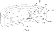
- FIG. 3 is a schematic cross-sectional structural diagram of the plantar assembly 120 in the embodiment of this application.
- the plantar assembly 120 is an assembly of the robot that directly contacts the environment. Different degrees of contact between the environment and the plantar assembly 120 may be reflected by reaction forces of different magnitudes and different directions applied by the environment to the plantar assembly 120.
- the plantar assembly 120 needs to install a sensor configured to measure information generated by the robot on the contact with the environment.
- the plantar assembly 120 may include: a plantar plate 1201, a first force sensor 1202, a distance sensor 1203, a posture sensor 1204, a seal ring 1205, and plantar rubber 1206.
- a contact surface of the plantar plate 1201 with the environment is a circular plane.
- the circular plane may provide an isotropic contact condition, and facilitates mechanical modeling of a plantar contact force by using a classical Coulomb friction cone model. is a static friction force, is a coefficient of static friction, and is a normal contact force.
- a bottom and an outer side of the plantar plate 1201 are cladded with a rubber pad as the plantar rubber 1206.
- the first force sensor 1202 is arranged between the bottom of the plantar plate 1201 and the plantar rubber 1206.
- the first force sensor 1202 may be an ionic thin-film force sensor, and is arranged between the bottom of the plantar plate 1201 and the plantar rubber 1206 and is of a ring shape.
- the ionic thin-film force sensor may be configured to measure a normal contact force between the obstacle in contact with the plantar plate 1201 and the plantar plate 1201. By using the ionic thin-film force sensor, the accuracy of measuring the normal contact force can be improved, a space occupied by the force sensor of the plantar assembly 120 is reduced, and a weight of the plantar assembly 120 is also reduced.
- the distance sensor 1203 is arranged between the lower part of the plantar plate 1201 and the plantar rubber 1206 at the bottom.
- the distance sensor 1203 is arranged in a central area of the first force sensor 1202 that is of a ring shape, and the distance sensor 1203 may be a thin-film distance sensor.
- the thin-film distance sensor may be configured to measure a distance between the plantar rubber 1206 and the obstacle when the plantar plate 1201 is being close to or away from the obstacle in the environment.
- a thickness of the plantar rubber 1206 at a portion under the thin-film distance sensor is smaller than a thickness of the plantar rubber 1206 at another portion of the plantar assembly 120.
- the thin-film distance sensor may obtain a better measurement effect and have a large measurement distance. Measured values of a distance between the plantar rubber 1206 and the external environment and the normal contact force that are detected by the thin-film distance sensor and the ionic thin-film force sensor are all uploaded to a control unit 130, so that a control effect of the control unit 130 on the leg assembly 100 can be improved.
- the posture sensor 1204 is an inertial measurement unit (IMU).
- the IMU is a device configured to measure a three-axis posture angle and an acceleration of an object.
- postures of a coordinate system of the IMU relative to a coordinate system of the plantar plate 1201 may be arbitrarily arranged, and after the arranged IMU and plantar plate are calibrated, a three-axis posture angle of the plantar plate 1201 may be measured as a posture measurement value.
- a spatial orientation of the plantar plate 1201 is determined based on the posture measurement value.
- the coordinate system of the IMU and the coordinate system of the plantar plate 1201 are aligned.
- the arranged IMU and plantar plate may not be calibrated, and the posture measurement value is directly measured through the IMU.
- the IMU measures Euler angles of the plantar plate 1201 in a geographic absolute coordinate system.
- the Euler angles represent a series of three-dimensional basic rotation angles, that is, a series of rotation angles around coordinate axes of a coordinate system. For example, an angle is first formed by rotating around a z-axis, an angle is formed by rotating around an x-axis, and an angle is formed by rotating around a z-axis. According to the obtained Euler angles, the spatial orientation of the plantar plate 1201 is obtained.
- a shock absorbing gasket is arranged between the posture sensor 1204 and a metal structure part (the plantar plate 1201), to reduce interference on measurement of the posture sensor 1204 or physical damage to the posture sensor 1204 caused by a landing impact of the plantar plate 1201.
- a seal ring 1205 is configured to improve a connection effect with an upper cover of the plantar plate.
- the plantar plate 1201 is a metal structure part with a void or a groove.
- the first force sensor 1202, the distance sensor 1203, and the posture sensor 1204 are connected to the shank connector 1102 via connection wires passing through the void or the groove of the metal structure part.
- a contact surface of the plantar plate 1201 with the ground may be a circular plane.
- the connection wires may be connected to the control unit 130 in the robot body 140 through the shank connector 1102.
- a bottom and an outer side of the metal structure part are cladded with plantar rubber 1206. That is, when the plantar plate 1201 is implemented as the metal structure part, the bottom and the outer side of the plantar plate 1201 are cladded with the plantar rubber 1206.
- the first force sensor 1202 is an ionic thin-film force sensor.
- the ionic thin-film force sensor is arranged between the plantar rubber 1206 and the bottom of the metal structure part.
- the ionic thin-film force sensor is of a ring shape.
- the distance sensor 1203 is a thin-film distance sensor.
- the thin-film distance sensor is centrally arranged between the plantar rubber 1206 and the bottom of the metal structure part. A thickness of a portion of the plantar rubber 1206 under the thin-film distance sensor is smaller than a thickness of the plantar rubber 1206 at another portion.
- the posture sensor 1204 is arranged in the groove of the metal structure part.
- a shock absorbing gasket is installed between the posture sensor 1204 and the metal structure part (the plantar plate 1201).
- the joint assembly 150 includes a joint ball socket 1501, a ball joint 1502, an elastic assembly 1503, a lower snap ring 1506, a flexible cover 1505, and an upper snap ring 1504.
- the plantar plate 1201 drives the joint ball socket 1501 to rotate relative to the ball joint 1502 with three degrees of freedom, so that the plantar plate 1201 adapts to fit the contact surface.
- the elastic assembly 1503 includes a conical return spring.
- the conical return spring is configured to be in a passively compressed state in a case that the plantar plate 1201 is in contact with an obstacle, and release stored energy (elastic potential energy) in a case that the plantar plate is separated from the obstacle, so as to drive the plantar plate 1201 to restore to an initial state.
- the joint ball socket 1501 includes a limiting structure.
- the joint ball socket with the limiting structure are provided with low front and rear edges and high left and right edges.
- the joint assembly 150 may enable the plantar assembly 120 to have a certain degree of freedom, so that the plantar assembly 120 may rotate by a certain degree.
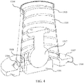
- FIG. 4 is a schematic cross-sectional structural diagram of the joint assembly 150 in an embodiment of this application.
- the joint assembly 150 may include: a joint ball socket 1501, a ball joint 1502, an elastic assembly 1503, an upper snap ring 1504, a flexible cover 1505, a lower snap ring 1506, an upper cover 1507 of a plantar plate, a ball socket involute groove 1508, and a seal ring groove 1509.
- the plantar assembly 120 and the joint assembly 150 are connected with each other by tightly fitting the seal ring groove 1509 on the upper cover 1507 of the plantar plate and the seal ring 1205 in the plantar assembly 120 shown in FIG. 3 .
- the joint ball socket 1501 may rotate relative to the ball joint 1502 with three degrees of freedom.
- the joint ball socket 1501 includes a limiting structure.
- the joint ball socket with the limiting structure are provided with low front and rear edges and high left and right edges.
- the joint assembly 150 expands a motion range through the low front and rear edges of the joint ball socket, and for a degree of freedom in roll, the joint assembly 150 maintains a small motion range through the high left and right edges of the joint ball socket.
- the low edges of the joint ball socket 1501 may form the ball socket involute groove 1508.
- the degree of freedom in pitch of the ball joint 1502 may be improved.
- a ball head of the ball joint 1502 is adapted to a size of the joint ball socket 1501, to ensure connection strength between the joint ball socket 1501 and the ball head of the ball joint 1502, thereby preventing disconnection.
- the plantar plate 1201 is configured to drive, in response to a reaction force from a contact surface, the joint ball socket 1501 to rotate relative to the ball joint 1502 with three degrees of freedom, so that the plantar plate 1201 is adapted to fit the contact surface.
- the reaction force applied to the plantar plate 1201 by the obstacle drives the joint ball socket 1501 to adaptively adjust angles of directions of the three degrees of freedom, so as to adjust posture angles of the connected plantar plate 1201 in the directions of the three degrees of freedom, thereby adaptively adjusting a spatial orientation of the plantar plate 1201.
- the angles in the directions of the three degrees of freedom of the joint ball socket 1501 may be adjusted relative to the ball joint 1502.
- an encoder is arranged on the ball joint 1502, and a rotation angle of the ball joint 1502 may be directly measured through the encoder, so as to obtain the posture angles of the connected plantar plate 1201.
- the elastic assembly 1503 is arranged in the joint assembly 150.
- the elastic assembly 1503 may be a conical return spring. One end of the conical return spring is connected to the plantar plate 1201, and another end is connected to the shank connector 1102.
- the elastic assembly 1503 includes a conical return spring.
- the conical return spring is configured to be in a passively compressed state in a case that the plantar plate 1201 is in contact with the obstacle, and release stored energy in a case that the plantar plate 1201 is separated from the obstacle, to drive the plantar plate 1201 to restore to an initial state.
- the conical return spring is configured to be in the passively compressed state in a case that the plantar plate 1201 is in contact with the obstacle.
- the conical return spring is further configured to release the stored energy (elastic potential energy) in a case that the plantar plate 1201 is separated from the obstacle, to drive the plantar plate 1201 to restore to the initial state.
- the conical return spring When the ball joint 1502 arbitrarily rotates in the three degrees of freedom, the conical return spring is in the passively compressed state. When the plantar plate is separated from the obstacle, the conical return spring releases the stored energy and drives the plantar plate 1201 to restore to the initial state. For example, when the plantar plate 1201 is separated from the obstacle, the ball joint 1502 restores the angle of the directions of the three degrees of freedom to an initial angle through the conical return spring, to adjust the posture angles of the connected plantar plate 1201 in the directions of the three degrees of freedom to initial angles, so as to adjust a spatial orientation of the plantar plate 1201 to restore to an initial spatial orientation.
- the elastic assembly 1503 is made of an elastic cladding material. Compared with the elastic cladding material, the conical return spring has more stable and consistent elastic performance, and in turn has higher reliability for the return effect of the plantar plate 1201.
- a flexible cover 1505 is cladded on an outer side of the elastic assembly 1503.
- One end of the flexible cover 1505 may be sleeved on the upper cover 1507 of the plantar plate, and another end may be sleeved on the shank connector 1102.
- the upper snap ring 1504 and the lower snap ring 1506 in the joint assembly 150 may be configured to fix two ends of the flexible cover 1505 respectively on the upper cover 1507 of the plantar plate and the shank connector 1102, so that the joint assembly 150 is sealed, thereby achieving purposes of dustproof and waterproof.
- the elastic assembly 1503 includes a conical return spring.
- the conical return spring is sleeved on a periphery of the ball joint 1502, and a lower end of the conical return spring is connected to the plantar plate 1201, and an upper end is connected to the shank connector 1102.
- FIG. 5 is a schematic cross-sectional structural diagram of the connection assembly 110 in an embodiment of this application.
- the connection assembly 110 may connect a shank portion of a robot body 140 with a joint assembly 150.
- the connection assembly 110 may include: a second force sensor 1101, a shank connector 1102, a lower flange 1103, a wiring hole 1104, and an upper flange 1105.
- the second force sensor 1101 is a six-axis force sensor.
- the six-axis force sensor may be configured to measure a resultant force vector of reaction forces applied to the plantar plate 1201.
- a front end of the six-axis force sensor may be connected to a ball head flange of a ball joint 1502, and a rear end of the six-axis force sensor may be connected to the lower flange 1103, to conduct a force or torque.
- the shank connector 1102 is a triangular prism connector. Setting the shank connector in the shape of a triangular prism may facilitate connection between the upper flange 1105 and the lower flange 1103.
- the wiring hole 1104 is arranged in the shank connector.
- the wiring hole 1104 may be used as a channel for arranging connection wires, and the connection wires may be used for a first force sensor 1202, a distance sensor 1203, a posture sensor 1204, an encoder, and the second force sensor 1101 to upload measurement data to a control unit 130.
- a flexible cover 1505 is connected to the lower flange of the connector assembly by using an upper snap ring, achieving waterproof and dustproof protection for an entire foot of the robot.
- the shank connector 1102 is a hollow triangular prism connector; and a lower end of the shank connector 1102 is connected to the second force sensor 1101 by using a flange.
- control unit 130 is arranged in the robot body 140.
- the leg assembly can perform comprehensive detection of a contact environment, and upload detection results of the sensors to a control unit, so that the control unit comprehensively controls the robot based on the detection results of the sensors.
- the control unit rather than obtaining a measurement result in a single aspect through detection of a single pressure sensor, more types and quality of perception information about the environment are obtained by the robot, so that the control unit can obtain a more comprehensive detection result, and control the robot to move through the leg assembly according to the detection result, thereby greatly improving a control effect on the leg assembly of the robot, thus extending application scenarios of a legged robot.
- the leg assembly for a robot may be applied to different legged robots such as bipedal humanoid robots, multi-legged robots, or may be applied to ends of various series connection or parallel connection multi-joint robots, to interact with the environment.
- the leg assembly When the leg assembly is applied to a legged robot platform as a planta, the leg assembly may adapt to a complex terrain and provide, in real time, effective feedback of a contact state for a control algorithm, thereby improving a balance control effect and a passing capability of the robot.
- the leg assembly When the leg assembly is applied to a robot platform such as a robotic arm as an end executor, the leg assembly may provide rich environmental perception information for the robot, and realize an adaptive and safe contact and interaction between the robot and the environment.
- the legged robot may be a bipedal humanoid robot, and the robot includes a robot body 140, a control unit 130, and a leg assembly 100.
- the leg assembly 100 is configured to execute a movement instruction, so that the robot moves according to the movement instruction.
- the movement instructions may be sent by the control unit 130 to the leg assembly 100, and the movement instructions may include a walking instruction and a running instruction.
- Different types of sensors are installed on the leg assembly 100 to detect environmental information at the current moment.
- the leg assembly 100 is electrically connected to the control unit 130, to upload the collected environmental information at the current moment to the control unit 130.
- the control unit 130 analyzes the environmental information, and sends the movement instruction to the leg assembly 100, to control movement of the robot at a next moment.
- the leg assembly can perform comprehensive detection of a contact environment, and upload detection results of the sensors to a control unit, so that the control unit comprehensively controls the robot based on the detection results of the sensors.
- the control unit may obtain more comprehensive detection result, and control the robot to move through the leg assembly according to the detection result, which greatly improves a control effect on the leg assembly of the robot, thereby expanding application scenarios of a legged robot.
- FIG. 7 is a flowchart of a method for applying a leg assembly for a robot to perform sensor detection according to an exemplary embodiment of this application.
- the method for performing sensor detection is executed by the leg assembly.
- the method for performing sensor detection may include the following steps 701 to 705.
- step 701 a normal reaction force applied to a plantar plate when the plantar plate is in contact with an obstacle is detected by using a first force sensor, to obtain data of the normal reaction force.
- step 702 a distance between the plantar plate and the obstacle is detected in real time by using a distance sensor, to obtain data of the distance in real time.
- step 703 a spatial orientation of the plantar plate is detected by using a posture sensor, to obtain information about the spatial orientation of the plantar plate.
- step 704 a resultant force of reaction forces applied to the plantar plate when the plantae plated is in contact with the obstacle is detected by using a second force sensor, to obtain vector data of the resultant force.
- step 705 the data of the normal reaction force, the data of the distance, the information about the spatial orientation of the plantar plate, and the vector data of the resultant force of the applied reaction forces are uploaded to a control unit.
- the data of the normal reaction force, the data of the distance, the information about the spatial orientation of the plantar plate, and the vector data of the resultant force of the applied reaction forces are detected by corresponding sensors in real time.
- step 701, step 702, step 703, and step 704 may be performed simultaneously, or may not be performed simultaneously.
- the control unit may analyze at least two of the data of the normal reaction force, the data of the distance, the information about the spatial orientation of the plantar plate, and the vector data of the resultant force of the applied reaction forces, to perceive the current environment.
- the leg assembly can perform comprehensive detection of a contact environment, and upload detection results of the sensors to a control unit, so that the control unit comprehensively controls the robot based on the detection results of the sensors.
- the control unit may obtain a more comprehensive detection result, and control the robot to move through the leg assembly according to the detection result, which greatly improves a control effect on the leg assembly of the robot, thereby expanding application scenarios of a legged robot.
Landscapes
- Engineering & Computer Science (AREA)
- Mechanical Engineering (AREA)
- Chemical & Material Sciences (AREA)
- Combustion & Propulsion (AREA)
- Transportation (AREA)
- Robotics (AREA)
- Human Computer Interaction (AREA)
- Manipulator (AREA)
Abstract
Description
- This application claims priority to
Chinese Patent Application No. 202010802986.X, entitled "LEG ASSEMBLY AND DEVICE FOR ROBOT" and filed on August 11, 2020 - At present, increasingly more legged robots are designed and applied in daily life. In a process of designing a legged robot, it is required to consider how to control the legged robot to walk and move normally in different environments, to solve the problem of unstable walking and moving of the legged robots that is caused by an unknown environment.
- In the conventional art, a pressure sensor is installed on a foot of a legged robot, to sense the magnitude and direction of a pressure contacted by the foot of the legged robot, and a walking mode of the legged robot is adjusted according to the detected information of the pressure, for example, a stride or a walking direction is adjusted, to realize normal walking of the legged robot in some unknown environments.
- However, in a process of practically applying the solutions in the conventional art, there is a problem that the legged robot cannot be controlled to move normally in some unknown environments by adjusting foot postures because the legged robot has a little perception information about the environment, resulting in limited application scenarios of the legged robot.
- A leg assembly and device for a robot are provided according to this application. The technical solutions are described as follows.
- In an aspect, a leg assembly for a robot is provided, the
leg assembly 100 includes: aconnection assembly 110 and aplantar assembly 120. Theconnection assembly 110 is configured to connect theleg assembly 100 with arobot body 140. Theplantar assembly 120 includes aplantar plate 1201, afirst force sensor 1202, adistance sensor 1203, and aposture sensor 1204. Theconnection assembly 110 includes asecond force sensor 1101 and ashank connector 1102. Thefirst force sensor 1202, thedistance sensor 1203, theposture sensor 1204, and thesecond force sensor 1101 are electrically connected to acontrol unit 130. Thefirst force sensor 1202 is configured to detect a normal reaction force applied to theplantar plate 1201 when the plantar plate (1201) is in contact with an obstacle. Thedistance sensor 1203 is configured to detect a distance between theplantar plate 1201 and the obstacle in real time. Theposture sensor 1204 is configured to detect a spatial orientation of theplantar plate 1201. Thesecond force sensor 1101 is configured to detect a resultant force of reaction forces applied to theplantar plate 1201 when the plantar plate (1201) is in contact with the obstacle. - In an embodiment, the
plantar assembly 120 is connected with theconnection assembly 110 through ajoint assembly 150. Thejoint assembly 150 includes ajoint ball socket 1501, aball joint 1502, and anelastic assembly 1503. Theplantar plate 1201 is configured to drive, in response to a reaction force from a contact surface, thejoint ball socket 1501 to rotate relative to theball joint 1502 with three degrees of freedom, to adapt the plantar plate to fit the contact surface. - In an embodiment, the
elastic assembly 1503 includes a conical return spring. The conical return spring is configured to be in a passively compressed state in a case that theplantar plate 1201 is in contact with the obstacle. The conical return spring is further configured to release stored energy in a case that theplantar plate 1201 is separated from the obstacle, to drive theplantar plate 1201 to restore to an initial state. - In an embodiment, the
joint ball socket 1501 includes a limiting structure. The joint ball socket with the limiting structure are provided with low front and rear edges and high left and right edges. - In an embodiment, the
plantar plate 1201 is a metal structure part with a void or a groove. Thefirst force sensor 1202, thedistance sensor 1203, and theposture sensor 1204 are connected to thecontrol unit 130 via connection wires passing through the void or the groove of the metal structure part. - In an embodiment, a bottom and an outer side of the metal structure part are cladded with
plantar rubber 1206. - In an embodiment, the
first force sensor 1202 is an ionic thin-film force sensor. The ionic thin-film force sensor is arranged between theplantar rubber 1206 and the bottom of the metal structure part, and the ionic thin-film force sensor is of a ring shape. - In an embodiment, the
distance sensor 1203 is a thin-film distance sensor. The thin-film distance sensor is centrally arranged between theplantar rubber 1206 and the bottom of the metal structure part. A thickness of theplantar rubber 1206 at a portion under the thin-film distance sensor is smaller than a thickness of theplantar rubber 1206 at another portion. - In an embodiment, the
posture sensor 1204 is arranged in the groove of the metal structure part. - In an embodiment, the
elastic assembly 1503 includes a conical return spring. The conical return spring is sleeved on a periphery of theball joint 1502, and a lower end of the conical return spring is connected to theplantar plate 1201, and an upper end of the conical return spring is connected to theshank connector 1102. - In an embodiment, the
shank connector 1102 is a hollow triangular prism connector. A lower end of theshank connector 1102 is connected to thesecond force sensor 1101 by using a flange. - In an embodiment, the
posture sensor 1204 is an inertial measurement unit (IMU). - In an embodiment, the
second force sensor 1101 is a six-axis force sensor. - In an embodiment, the
control unit 130 is arranged in therobot body 140. - In an aspect, a leg device for a robot is provided, the device includes a
robot body 140 and theleg assembly 100. - The technical solutions according to this application may realize the following beneficial effects. In the solutions in the embodiments of this application, by installing a first force sensor, a distance sensor, a posture sensor, and a second force sensor in a leg assembly for a robot, the leg assembly can perform comprehensive detection of a contact environment, and upload detection results of the sensors to a control unit, so that the control unit comprehensively controls the robot based on the detection results of the sensors. With the solutions in this application, rather than obtaining a measurement result in a single aspect through detection of a single pressure sensor, more types and quality of perception information about the environment are obtained by the robot, so that the control unit can obtain a more comprehensive detection result, and control the robot to move through the leg assembly according to the detection result, thereby greatly improving a control effect on the leg assembly of the robot, thus extending application scenarios of a legged robot.
- The drawings herein are included in this specification and form a part of this specification, illustrate embodiments consistent with the present disclosure, and are used to explain the principles of the present disclosure together with this specification.
-
FIG. 1 is a constructional diagram of a leg assembly for a robot according to an exemplary embodiment. -
FIG. 2 is a schematic structural diagram of a leg assembly according to an exemplary embodiment. -
FIG. 3 is a schematic cross-sectional structural diagram of theplantar assembly 120 in the embodiment shown inFIG. 2 . -
FIG. 4 is a schematic cross-sectional structural diagram of thejoint assembly 150 in the embodiment shown inFIG. 2 . -
FIG. 5 is a schematic cross-sectional structural diagram of theconnection assembly 110 in the embodiment shown inFIG. 2 . -
FIG. 6 is a schematic diagram of a robot device to which a leg assembly is applied according to an exemplary embodiment. -
FIG. 7 is a flowchart of a method for applying a leg assembly for a robot to perform sensor detection according to an exemplary embodiment. - Exemplary embodiments are described in detail herein, and examples of the exemplary embodiments are shown in the drawings. When the following description involves the drawings, unless otherwise indicated, the same numerals in different drawings represent the same or similar elements. The following exemplary embodiments do not represent all embodiments that are consistent with this application. On the contrary, the exemplary embodiments are merely examples of devices and methods that are described in detail and that are consistent with the claims and some aspects of this application.
- It is to be understood that, "several" mentioned in this specification means one or more, and "plurality of' means two or more. And/or describes an association relationship for describing associated objects and represents that three relationships may exist. For example, A and/or B may represent the following three cases: only A exists, both A and B exist, and only B exists. The character "/" in this specification generally indicates an "or" relationship between the associated objects.
- For ease of understanding, several terms involved in this application are explained below.
- Artificial intelligence (AI) indicates a theory, method, technology, and application system that uses a digital computer or a machine controlled by the digital computer to simulate, extend, and expand human intelligence, perceive an environment, obtain knowledge, and use knowledge to obtain an optimal result. In other words, the AI indicates a comprehensive technology of computer science, which attempts to understand essence of intelligence and produces a new intelligent machine that can respond in a manner similar to human intelligence. The AI is used to study the design principles and implementation methods of various intelligent machines, to enable the machines to have the functions of perception, reasoning, and decision-making.
- The AI technology involves a comprehensive discipline, and relates to a wide range of fields including both hardware-level technologies and software-level technologies. The basic AI technologies generally include technologies such as a sensor, a dedicated AI chip, cloud computing, distributed storage, a big data processing technology, an operating/interaction system, and electromechanical integration. The AI software technologies mainly include several major directions such as a computer vision technology, a speech processing technology, a natural language processing technology, and machine learning/deep learning.
- With the research and progress of the AI technology, the AI technology is studied and applied in many fields such as a common smart home, a smart wearable device, a virtual assistant, a smart speaker, smart marketing, unmanned driving, automatic driving, an unmanned aerial vehicle, a robot, smart medical care, and smart customer service. It is believed that with the development of technologies, the AI technology will be applied to more fields, and play an increasingly important role.
-
FIG. 1 is a constructional diagram of a leg assembly for a robot according to an exemplary embodiment of this application. As shown inFIG. 1 , theleg assembly 100 includes: aconnection assembly 110 and aplantar assembly 120. Theconnection assembly 110 is configured to connect theleg assembly 100 with arobot body 140. Theplantar assembly 120 includes aplantar plate 1201, afirst force sensor 1202, adistance sensor 1203, and aposture sensor 1204. Theconnection assembly 110 includes asecond force sensor 1101 and ashank connector 1102. Thefirst force sensor 1202, thedistance sensor 1203, theposture sensor 1204, and thesecond force sensor 1101 are electrically connected to acontrol unit 130. Thefirst force sensor 1202 is configured to detect a normal reaction force applied to theplantar plate 1201 when theplantar plate 1201 is in contact with an obstacle. Thedistance sensor 1203 is configured to detect a distance between theplantar plate 1201 and the obstacle in real time. Theposture sensor 1204 is configured to detect a spatial orientation of theplantar plate 1201. Thesecond force sensor 1101 is configured to detect a resultant force of reaction forces applied to theplantar plate 1201 when theplantar plate 1201 is in contact with the obstacle. - Therefore, by installing a first force sensor, a distance sensor, a posture sensor, and a second force sensor in a leg assembly for a robot, the leg assembly can perform comprehensive detection of a contact environment, and upload detection results of the sensors to a control unit, so that the control unit comprehensively controls the robot based on the detection results of the sensors. With the solutions in this application, rather than obtaining a measurement result in a single aspect through detection of a single pressure sensor, more types and quality of perception information about the environment are obtained by the robot, so that the control unit can obtain a more comprehensive detection result, and control the robot to move through the leg assembly according to the detection result, thereby greatly improving a control effect on the leg assembly of the robot, thus extending application scenarios of a legged robot.
-
FIG. 2 is a schematic structural diagram of a leg assembly according to an exemplary embodiment of this application. As shown inFIG. 2 , theleg assembly 100 includes: aconnection assembly 110 and aplantar assembly 120. Theconnection assembly 110 is configured to connect theleg assembly 100 with arobot body 140. Theplantar assembly 120 includes aplantar plate 1201, afirst force sensor 1202, adistance sensor 1203, and aposture sensor 1204. Theconnection assembly 110 includes asecond force sensor 1101 and ashank connector 1102. Thefirst force sensor 1202, thedistance sensor 1203, theposture sensor 1204, and thesecond force sensor 1101 are electrically connected to acontrol unit 130. Thefirst force sensor 1202 is configured to detect a normal reaction force applied to theplantar plate 1201 when theplantar plate 1201 is in contact with an obstacle. Thedistance sensor 1203 is configured to detect a distance between theplantar plate 1201 and the obstacle in real time. Theposture sensor 1204 is configured to detect a spatial orientation of theplantar plate 1201. Thesecond force sensor 1101 is configured to detect a resultant force of reaction forces applied to theplantar plate 1201 when theplantar plate 1201 is in contact with the obstacle. - In an embodiment, the
plantar assembly 120 is connected with theconnection assembly 110 through ajoint assembly 150. Thecontrol unit 130 may be arranged in theleg assembly 100. Alternatively, thecontrol unit 130 may be arranged in therobot body 140. - For example,
FIG. 3 is a schematic cross-sectional structural diagram of theplantar assembly 120 in the embodiment of this application. As shown inFIG. 3 , theplantar assembly 120 is an assembly of the robot that directly contacts the environment. Different degrees of contact between the environment and theplantar assembly 120 may be reflected by reaction forces of different magnitudes and different directions applied by the environment to theplantar assembly 120. In order to accurately measure an influence generated by the environment on theplantar assembly 120, theplantar assembly 120 needs to install a sensor configured to measure information generated by the robot on the contact with the environment. Theplantar assembly 120 may include: aplantar plate 1201, afirst force sensor 1202, adistance sensor 1203, aposture sensor 1204, aseal ring 1205, andplantar rubber 1206. - In an embodiment, a contact surface of the
plantar plate 1201 with the environment is a circular plane. The circular plane may provide an isotropic contact condition, and facilitates mechanical modeling of a plantar contact force by using a classical Coulomb friction cone model.
is a static friction force, is a coefficient of static friction, and is a normal contact force. - In an embodiment, to increase a friction coefficient of the plantar plate, provide a certain degree of buffering to an impact to the robot when the robot sets foot on the ground, and protect the
plantar plate 1201. In addition, a bottom and an outer side of theplantar plate 1201 are cladded with a rubber pad as theplantar rubber 1206. - In an embodiment, the
first force sensor 1202 is arranged between the bottom of theplantar plate 1201 and theplantar rubber 1206. Thefirst force sensor 1202 may be an ionic thin-film force sensor, and is arranged between the bottom of theplantar plate 1201 and theplantar rubber 1206 and is of a ring shape. The ionic thin-film force sensor may be configured to measure a normal contact force between the obstacle in contact with theplantar plate 1201 and theplantar plate 1201. By using the ionic thin-film force sensor, the accuracy of measuring the normal contact force can be improved, a space occupied by the force sensor of theplantar assembly 120 is reduced, and a weight of theplantar assembly 120 is also reduced. - In an embodiment, the
distance sensor 1203 is arranged between the lower part of theplantar plate 1201 and theplantar rubber 1206 at the bottom. Thedistance sensor 1203 is arranged in a central area of thefirst force sensor 1202 that is of a ring shape, and thedistance sensor 1203 may be a thin-film distance sensor. The thin-film distance sensor may be configured to measure a distance between theplantar rubber 1206 and the obstacle when theplantar plate 1201 is being close to or away from the obstacle in the environment. - In an embodiment, a thickness of the
plantar rubber 1206 at a portion under the thin-film distance sensor is smaller than a thickness of theplantar rubber 1206 at another portion of theplantar assembly 120. By reducing the thickness of the portion of theplantar rubber 1206 under the thin-film distance sensor, the thin-film distance sensor may obtain a better measurement effect and have a large measurement distance. Measured values of a distance between theplantar rubber 1206 and the external environment and the normal contact force that are detected by the thin-film distance sensor and the ionic thin-film force sensor are all uploaded to acontrol unit 130, so that a control effect of thecontrol unit 130 on theleg assembly 100 can be improved. - In an embodiment, the
posture sensor 1204 is an inertial measurement unit (IMU). The IMU is a device configured to measure a three-axis posture angle and an acceleration of an object. - In an embodiment, postures of a coordinate system of the IMU relative to a coordinate system of the
plantar plate 1201 may be arbitrarily arranged, and after the arranged IMU and plantar plate are calibrated, a three-axis posture angle of theplantar plate 1201 may be measured as a posture measurement value. A spatial orientation of theplantar plate 1201 is determined based on the posture measurement value. - In an embodiment, the coordinate system of the IMU and the coordinate system of the
plantar plate 1201 are aligned. When the coordinate system of the IMU and the coordinate system of theplantar plate 1201 are aligned, the arranged IMU and plantar plate may not be calibrated, and the posture measurement value is directly measured through the IMU. The IMU measures Euler angles of theplantar plate 1201 in a geographic absolute coordinate system. The Euler angles represent a series of three-dimensional basic rotation angles, that is, a series of rotation angles around coordinate axes of a coordinate system. For example, an angle is first formed by rotating around a z-axis, an angle is formed by rotating around an x-axis, and an angle is formed by rotating around a z-axis. According to the obtained Euler angles, the spatial orientation of theplantar plate 1201 is obtained. - In an embodiment, a shock absorbing gasket is arranged between the
posture sensor 1204 and a metal structure part (the plantar plate 1201), to reduce interference on measurement of theposture sensor 1204 or physical damage to theposture sensor 1204 caused by a landing impact of theplantar plate 1201. - In an embodiment, a
seal ring 1205 is configured to improve a connection effect with an upper cover of the plantar plate. - In an embodiment, the
plantar plate 1201 is a metal structure part with a void or a groove. Thefirst force sensor 1202, thedistance sensor 1203, and theposture sensor 1204 are connected to theshank connector 1102 via connection wires passing through the void or the groove of the metal structure part. A contact surface of theplantar plate 1201 with the ground may be a circular plane. When thecontrol unit 130 is arranged in therobot body 140, the connection wires may be connected to thecontrol unit 130 in therobot body 140 through theshank connector 1102. - In an embodiment, a bottom and an outer side of the metal structure part are cladded with
plantar rubber 1206. That is, when theplantar plate 1201 is implemented as the metal structure part, the bottom and the outer side of theplantar plate 1201 are cladded with theplantar rubber 1206. - In an embodiment, the
first force sensor 1202 is an ionic thin-film force sensor. The ionic thin-film force sensor is arranged between theplantar rubber 1206 and the bottom of the metal structure part. The ionic thin-film force sensor is of a ring shape. - In an embodiment, the
distance sensor 1203 is a thin-film distance sensor. The thin-film distance sensor is centrally arranged between theplantar rubber 1206 and the bottom of the metal structure part. A thickness of a portion of theplantar rubber 1206 under the thin-film distance sensor is smaller than a thickness of theplantar rubber 1206 at another portion. - In an embodiment, the
posture sensor 1204 is arranged in the groove of the metal structure part. - In an embodiment, a shock absorbing gasket is installed between the
posture sensor 1204 and the metal structure part (the plantar plate 1201). Thejoint assembly 150 includes ajoint ball socket 1501, a ball joint 1502, anelastic assembly 1503, alower snap ring 1506, aflexible cover 1505, and anupper snap ring 1504. In response to a reaction force applied to theplantar plate 1201, theplantar plate 1201 drives thejoint ball socket 1501 to rotate relative to the ball joint 1502 with three degrees of freedom, so that theplantar plate 1201 adapts to fit the contact surface. - In an embodiment, the
elastic assembly 1503 includes a conical return spring. The conical return spring is configured to be in a passively compressed state in a case that theplantar plate 1201 is in contact with an obstacle, and release stored energy (elastic potential energy) in a case that the plantar plate is separated from the obstacle, so as to drive theplantar plate 1201 to restore to an initial state. - In an embodiment, the
joint ball socket 1501 includes a limiting structure. The joint ball socket with the limiting structure are provided with low front and rear edges and high left and right edges. Thejoint assembly 150 may enable theplantar assembly 120 to have a certain degree of freedom, so that theplantar assembly 120 may rotate by a certain degree. For example,FIG. 4 is a schematic cross-sectional structural diagram of thejoint assembly 150 in an embodiment of this application. As shown inFIG. 4 , thejoint assembly 150 may include: ajoint ball socket 1501, a ball joint 1502, anelastic assembly 1503, anupper snap ring 1504, aflexible cover 1505, alower snap ring 1506, anupper cover 1507 of a plantar plate, a ballsocket involute groove 1508, and aseal ring groove 1509. - In an embodiment, the
plantar assembly 120 and thejoint assembly 150 are connected with each other by tightly fitting theseal ring groove 1509 on theupper cover 1507 of the plantar plate and theseal ring 1205 in theplantar assembly 120 shown inFIG. 3 . - In an embodiment, the
joint ball socket 1501 may rotate relative to the ball joint 1502 with three degrees of freedom. - In an embodiment, the
joint ball socket 1501 includes a limiting structure. The joint ball socket with the limiting structure are provided with low front and rear edges and high left and right edges. For a degree of freedom in pitch, thejoint assembly 150 expands a motion range through the low front and rear edges of the joint ball socket, and for a degree of freedom in roll, thejoint assembly 150 maintains a small motion range through the high left and right edges of the joint ball socket. The low edges of thejoint ball socket 1501 may form the ballsocket involute groove 1508. When the ballsocket involute groove 1508 is enlarged, the degree of freedom in pitch of the ball joint 1502 may be improved. A ball head of the ball joint 1502 is adapted to a size of thejoint ball socket 1501, to ensure connection strength between thejoint ball socket 1501 and the ball head of the ball joint 1502, thereby preventing disconnection. - In an embodiment, the
plantar plate 1201 is configured to drive, in response to a reaction force from a contact surface, thejoint ball socket 1501 to rotate relative to the ball joint 1502 with three degrees of freedom, so that theplantar plate 1201 is adapted to fit the contact surface. When theplantar plate 1201 is in contact with an obstacle, the reaction force applied to theplantar plate 1201 by the obstacle drives thejoint ball socket 1501 to adaptively adjust angles of directions of the three degrees of freedom, so as to adjust posture angles of the connectedplantar plate 1201 in the directions of the three degrees of freedom, thereby adaptively adjusting a spatial orientation of theplantar plate 1201. When theplantar plate 1201 is in contact with the obstacle, in order to adaptively adapt theplantar plate 1201 to fit the obstacle under different contact angles, the angles in the directions of the three degrees of freedom of thejoint ball socket 1501 may be adjusted relative to the ball joint 1502. - In an embodiment, an encoder is arranged on the ball joint 1502, and a rotation angle of the ball joint 1502 may be directly measured through the encoder, so as to obtain the posture angles of the connected
plantar plate 1201. - In an embodiment, when the
plantar plate 1201 is separated from the obstacle, in order to enable theplantar plate 1201 to restore to an initial spatial orientation state, theelastic assembly 1503 is arranged in thejoint assembly 150. Theelastic assembly 1503 may be a conical return spring. One end of the conical return spring is connected to theplantar plate 1201, and another end is connected to theshank connector 1102. - In an embodiment, the
elastic assembly 1503 includes a conical return spring. The conical return spring is configured to be in a passively compressed state in a case that theplantar plate 1201 is in contact with the obstacle, and release stored energy in a case that theplantar plate 1201 is separated from the obstacle, to drive theplantar plate 1201 to restore to an initial state. The conical return spring is configured to be in the passively compressed state in a case that theplantar plate 1201 is in contact with the obstacle. The conical return spring is further configured to release the stored energy (elastic potential energy) in a case that theplantar plate 1201 is separated from the obstacle, to drive theplantar plate 1201 to restore to the initial state. When the ball joint 1502 arbitrarily rotates in the three degrees of freedom, the conical return spring is in the passively compressed state. When the plantar plate is separated from the obstacle, the conical return spring releases the stored energy and drives theplantar plate 1201 to restore to the initial state. For example, when theplantar plate 1201 is separated from the obstacle, the ball joint 1502 restores the angle of the directions of the three degrees of freedom to an initial angle through the conical return spring, to adjust the posture angles of the connectedplantar plate 1201 in the directions of the three degrees of freedom to initial angles, so as to adjust a spatial orientation of theplantar plate 1201 to restore to an initial spatial orientation. - In an embodiment, the
elastic assembly 1503 is made of an elastic cladding material. Compared with the elastic cladding material, the conical return spring has more stable and consistent elastic performance, and in turn has higher reliability for the return effect of theplantar plate 1201. - In an embodiment, a
flexible cover 1505 is cladded on an outer side of theelastic assembly 1503. One end of theflexible cover 1505 may be sleeved on theupper cover 1507 of the plantar plate, and another end may be sleeved on theshank connector 1102. - In an embodiment, the
upper snap ring 1504 and thelower snap ring 1506 in thejoint assembly 150 may be configured to fix two ends of theflexible cover 1505 respectively on theupper cover 1507 of the plantar plate and theshank connector 1102, so that thejoint assembly 150 is sealed, thereby achieving purposes of dustproof and waterproof. - In an embodiment, the
elastic assembly 1503 includes a conical return spring. The conical return spring is sleeved on a periphery of the ball joint 1502, and a lower end of the conical return spring is connected to theplantar plate 1201, and an upper end is connected to theshank connector 1102. - For example,
FIG. 5 is a schematic cross-sectional structural diagram of theconnection assembly 110 in an embodiment of this application. As shown inFIG. 5 , theconnection assembly 110 may connect a shank portion of arobot body 140 with ajoint assembly 150. Theconnection assembly 110 may include: asecond force sensor 1101, ashank connector 1102, alower flange 1103, awiring hole 1104, and anupper flange 1105. - In an embodiment, the
second force sensor 1101 is a six-axis force sensor. The six-axis force sensor may be configured to measure a resultant force vector of reaction forces applied to theplantar plate 1201. A front end of the six-axis force sensor may be connected to a ball head flange of a ball joint 1502, and a rear end of the six-axis force sensor may be connected to thelower flange 1103, to conduct a force or torque. - In an embodiment, the
shank connector 1102 is a triangular prism connector. Setting the shank connector in the shape of a triangular prism may facilitate connection between theupper flange 1105 and thelower flange 1103. - In an embodiment, the
wiring hole 1104 is arranged in the shank connector. Thewiring hole 1104 may be used as a channel for arranging connection wires, and the connection wires may be used for afirst force sensor 1202, adistance sensor 1203, aposture sensor 1204, an encoder, and thesecond force sensor 1101 to upload measurement data to acontrol unit 130. - In an embodiment, a
flexible cover 1505 is connected to the lower flange of the connector assembly by using an upper snap ring, achieving waterproof and dustproof protection for an entire foot of the robot. - In an embodiment, the
shank connector 1102 is a hollow triangular prism connector; and a lower end of theshank connector 1102 is connected to thesecond force sensor 1101 by using a flange. - In an embodiment, the
control unit 130 is arranged in therobot body 140. - Therefore, by installing a first force sensor, a distance sensor, a posture sensor, and a second force sensor in a leg assembly for a robot, the leg assembly can perform comprehensive detection of a contact environment, and upload detection results of the sensors to a control unit, so that the control unit comprehensively controls the robot based on the detection results of the sensors. With the solutions in this application, rather than obtaining a measurement result in a single aspect through detection of a single pressure sensor, more types and quality of perception information about the environment are obtained by the robot, so that the control unit can obtain a more comprehensive detection result, and control the robot to move through the leg assembly according to the detection result, thereby greatly improving a control effect on the leg assembly of the robot, thus extending application scenarios of a legged robot.
- The leg assembly for a robot provided in this application may be applied to different legged robots such as bipedal humanoid robots, multi-legged robots, or may be applied to ends of various series connection or parallel connection multi-joint robots, to interact with the environment. When the leg assembly is applied to a legged robot platform as a planta, the leg assembly may adapt to a complex terrain and provide, in real time, effective feedback of a contact state for a control algorithm, thereby improving a balance control effect and a passing capability of the robot. When the leg assembly is applied to a robot platform such as a robotic arm as an end executor, the leg assembly may provide rich environmental perception information for the robot, and realize an adaptive and safe contact and interaction between the robot and the environment.
FIG. 6 is a schematic diagram a robot device to which a leg assembly is applied according to an exemplary embodiment of this application. As shown inFIG. 6 , the legged robot may be a bipedal humanoid robot, and the robot includes arobot body 140, acontrol unit 130, and aleg assembly 100. Theleg assembly 100 is configured to execute a movement instruction, so that the robot moves according to the movement instruction. The movement instructions may be sent by thecontrol unit 130 to theleg assembly 100, and the movement instructions may include a walking instruction and a running instruction. Different types of sensors are installed on theleg assembly 100 to detect environmental information at the current moment. Theleg assembly 100 is electrically connected to thecontrol unit 130, to upload the collected environmental information at the current moment to thecontrol unit 130. Thecontrol unit 130 analyzes the environmental information, and sends the movement instruction to theleg assembly 100, to control movement of the robot at a next moment. - Therefore, by installing a first force sensor, a distance sensor, a posture sensor, and a second force sensor in a leg assembly for a robot, the leg assembly can perform comprehensive detection of a contact environment, and upload detection results of the sensors to a control unit, so that the control unit comprehensively controls the robot based on the detection results of the sensors. With the solutions shown in this application, rather than obtaining a measurement result in a single aspect through detection of a single pressure sensor, more types and quality of perception information about the environment are obtained by the robot, so that the control unit may obtain more comprehensive detection result, and control the robot to move through the leg assembly according to the detection result, which greatly improves a control effect on the leg assembly of the robot, thereby expanding application scenarios of a legged robot.
-
FIG. 7 is a flowchart of a method for applying a leg assembly for a robot to perform sensor detection according to an exemplary embodiment of this application. The method for performing sensor detection is executed by the leg assembly. As shown inFIG. 7 , the method for performing sensor detection may include the followingsteps 701 to 705. - In
step 701, a normal reaction force applied to a plantar plate when the plantar plate is in contact with an obstacle is detected by using a first force sensor, to obtain data of the normal reaction force. - In
step 702, a distance between the plantar plate and the obstacle is detected in real time by using a distance sensor, to obtain data of the distance in real time. - In
step 703, a spatial orientation of the plantar plate is detected by using a posture sensor, to obtain information about the spatial orientation of the plantar plate. - In
step 704, a resultant force of reaction forces applied to the plantar plate when the plantae plated is in contact with the obstacle is detected by using a second force sensor, to obtain vector data of the resultant force. - In
step 705, the data of the normal reaction force, the data of the distance, the information about the spatial orientation of the plantar plate, and the vector data of the resultant force of the applied reaction forces are uploaded to a control unit. - In an embodiment, the data of the normal reaction force, the data of the distance, the information about the spatial orientation of the plantar plate, and the vector data of the resultant force of the applied reaction forces are detected by corresponding sensors in real time.
- In an embodiment,
step 701,step 702,step 703, and step 704 may be performed simultaneously, or may not be performed simultaneously. In addition, the control unit may analyze at least two of the data of the normal reaction force, the data of the distance, the information about the spatial orientation of the plantar plate, and the vector data of the resultant force of the applied reaction forces, to perceive the current environment. - Therefore, by installing a first force sensor, a distance sensor, a posture sensor, and a second force sensor in a leg assembly for a robot, the leg assembly can perform comprehensive detection of a contact environment, and upload detection results of the sensors to a control unit, so that the control unit comprehensively controls the robot based on the detection results of the sensors. With the solutions shown in this application, rather than obtaining a measurement result in a single aspect through detection of a single pressure sensor, more types and quality of perception information in the environment are obtained by the robot, so that the control unit may obtain a more comprehensive detection result, and control the robot to move through the leg assembly according to the detection result, which greatly improves a control effect on the leg assembly of the robot, thereby expanding application scenarios of a legged robot.
- After considering this specification and practicing the present disclosure, a person skilled in the art may easily conceive of other embodiments of this application. This application is intended to cover any variations, uses or adaptive changes of this application. Such variations, uses or adaptive changes follow the general principles of this application, and include well-known knowledge and conventional technical means in the art that are not disclosed in this application. This specification and the embodiments are considered as merely exemplary, and the scope and spirit of this application are defined in the claims.
- It is to be understood that this application is not limited to the precise structures described above and shown in the accompanying drawings, and various modifications and changes can be made without departing from the scope of this application. The scope of this application is only defined by the claims.
Claims (15)
- A leg assembly (100) for a robot, the leg assembly (100) comprising:a connection assembly (110), configured to connect the leg assembly (100) with a robot body (140); anda plantar assembly (120) comprising a plantar plate (1201), a first force sensor (1202), a distance sensor (1203), and a posture sensor (1204),the connection assembly (110) comprising a second force sensor (1101) and a shank connector (1102);the first force sensor (1202), the distance sensor (1203), the posture sensor (1204), and the second force sensor (1101) being electrically connected to a control unit (130);the first force sensor (1202) being configured to detect a normal reaction force applied to the plantar plate (1201) when the plantar plate (1201) is in contact with an obstacle;the distance sensor (1203) being configured to detect a distance between the plantar plate (1201) and the obstacle in real time;the posture sensor (1204) being configured to detect a spatial orientation of the plantar plate (1201); andthe second force sensor (1101) being configured to detect a resultant force of reaction forces applied to the plantar plate (1201) when the plantar plate (1201) is in contact with the obstacle.
- The assembly according to claim 1, wherein the plantar assembly (120) is connected with the connection assembly (110) through a joint assembly (150), andthe joint assembly (150) comprises a joint ball socket (1501), a ball joint (1502), and an elastic assembly (1503), andthe plantar plate (1201) is configured to drive, in response to a reaction force from a contact surface, the joint ball socket (1501) to rotate relative to the ball joint (1502) with three degrees of freedom, to adapt the plantar plate (1201) to fit the contact surface.
- The assembly according to claim 2, wherein the elastic assembly (1503) comprises a conical return spring, andthe conical return spring is configured to be in a passively compressed state in a case that the plantar plate (1201) is in contact with the obstacle; andthe conical return spring is further configured to release stored energy in a case that the plantar plate (1201) is separated from the obstacle, to drive the plantar plate (1201) to restore to an initial state.
- The assembly according to claim 2, wherein the joint ball socket (1501) comprises a limiting structure, and
the joint ball socket with the limiting structure is provided with low front and rear edges and high left and right edges. - The assembly according to claim 1, wherein the plantar plate (1201) is a metal structure part with a void or a groove, and the first force sensor (1202), the distance sensor (1203), and the posture sensor (1204) are connected to the control unit (130) via connection wires passing through the void or the groove of the metal structure part.
- The assembly according to claim 5, wherein a bottom and an outer side of the metal structure part are cladded with plantar rubber (1206).
- The assembly according to claim 5, wherein the first force sensor (1202) is an ionic thin-film force sensor, and
the ionic thin-film force sensor is arranged between the plantar rubber (1206) and the bottom of the metal structure part, and the ionic thin-film force sensor is of a ring shape. - The assembly according to claim 5, wherein the distance sensor (1203) is a thin-film distance sensor, and
the thin-film distance sensor is centrally arranged between the plantar rubber (1206) and the bottom of the metal structure part, and a thickness of the plantar rubber (1206) at a portion under the thin-film distance sensor is smaller than a thickness of the plantar rubber (1206) at another portion. - The assembly according to claim 5, wherein the posture sensor (1204) is arranged in the groove of the metal structure part.
- The assembly according to claim 2, wherein the elastic assembly (1503) comprises a conical return spring, and
the conical return spring is sleeved on a periphery of the ball joint (1502), and a lower end of the conical return spring is connected to the plantar plate (1201), and an upper end of the conical return spring is connected to the shank connector (1102). - The assembly according to claim 1, wherein the shank connector (1102) is a hollow triangular prism connector, and
a lower end of the shank connector (1102) is connected to the second force sensor (1101) by using a flange. - The assembly according to claim 1, wherein the posture sensor (1204) is an inertial measurement unit, IMU.
- The assembly according to claim 1, wherein the second force sensor (1101) is a six-axis force sensor.
- The assembly according to claim 1, wherein the control unit (130) is arranged in the robot body (140).
- A leg device for a robot, the device comprising:a robot body (140), andthe leg assembly (100) according to any one of claims 1 to 14.
Applications Claiming Priority (2)
| Application Number | Priority Date | Filing Date | Title |
|---|---|---|---|
| CN202010802986.XA CN111924020B (en) | 2020-08-11 | 2020-08-11 | Leg assemblies and equipment for robots |
| PCT/CN2021/084746 WO2022033044A1 (en) | 2020-08-11 | 2021-03-31 | Leg assembly and device for robot |
Publications (3)
| Publication Number | Publication Date |
|---|---|
| EP4043322A1 true EP4043322A1 (en) | 2022-08-17 |
| EP4043322A4 EP4043322A4 (en) | 2023-01-25 |
| EP4043322B1 EP4043322B1 (en) | 2025-02-26 |
Family
ID=73310755
Family Applications (1)
| Application Number | Title | Priority Date | Filing Date |
|---|---|---|---|
| EP21855100.0A Active EP4043322B1 (en) | 2020-08-11 | 2021-03-31 | Leg assembly and device for robot |
Country Status (5)
| Country | Link |
|---|---|
| US (1) | US12344336B2 (en) |
| EP (1) | EP4043322B1 (en) |
| JP (1) | JP7592353B2 (en) |
| CN (1) | CN111924020B (en) |
| WO (1) | WO2022033044A1 (en) |
Families Citing this family (6)
| Publication number | Priority date | Publication date | Assignee | Title |
|---|---|---|---|---|
| CN111924020B (en) | 2020-08-11 | 2022-07-12 | 腾讯科技(深圳)有限公司 | Leg assemblies and equipment for robots |
| CN113059568A (en) * | 2021-04-07 | 2021-07-02 | 哈尔滨理工大学 | a multifunctional foot |
| CN113401244A (en) * | 2021-06-21 | 2021-09-17 | 北京理工大学 | Automatic jack jacking disaster relief system based on sufficient robot |
| CN115610550B (en) * | 2021-07-13 | 2025-12-16 | Oppo广东移动通信有限公司 | Foot motion assembly and foot robot |
| CN116161141B (en) * | 2023-04-21 | 2023-06-30 | 成都理工大学 | Self-resetting damping foot end of heavy-load six-foot robot |
| CN117381763B (en) * | 2023-10-18 | 2024-05-31 | 芜湖藦卡机器人科技有限公司 | Automatic calibration detection mechanism and detection method for robot tool hand |
Family Cites Families (22)
| Publication number | Priority date | Publication date | Assignee | Title |
|---|---|---|---|---|
| US6243623B1 (en) * | 1997-01-31 | 2001-06-05 | Honda Giken Kogyo Kabushiki Kaisha | Leg type mobile robot control apparatus |
| CN101745910B (en) * | 2002-03-18 | 2014-11-05 | 索尼株式会社 | Mobile device and control method thereof |
| KR100956539B1 (en) * | 2002-04-26 | 2010-05-07 | 혼다 기켄 고교 가부시키가이샤 | Magnetic Posture Estimator for Legged Mobile Robot |
| EP2208581B1 (en) * | 2002-04-26 | 2011-09-07 | Honda Giken Kogyo Kabushiki Kaisha | Control device of legged mobile robot |
| WO2004030870A1 (en) * | 2002-10-01 | 2004-04-15 | Sony Corporation | Robot device and control method of robot device |
| JP4483254B2 (en) * | 2002-10-01 | 2010-06-16 | ソニー株式会社 | Robot apparatus and control method of robot apparatus |
| KR100835361B1 (en) * | 2003-08-29 | 2008-06-04 | 삼성전자주식회사 | Walking Robot Using Simple Ground Reaction Sensor and Its Control Method |
| JP4466715B2 (en) * | 2007-10-25 | 2010-05-26 | トヨタ自動車株式会社 | Legged robot and control method thereof |
| CN202413981U (en) * | 2012-01-19 | 2012-09-05 | 浙江大学 | Flat bottom foot structures of multi-foot walking robot |
| JP2013208294A (en) * | 2012-03-30 | 2013-10-10 | Equos Research Co Ltd | Walking device and walking program |
| CN103204190B (en) * | 2013-03-11 | 2015-06-24 | 大连理工大学 | Robot foot mechanism |
| CN104434470B (en) * | 2014-12-04 | 2017-01-04 | 电子科技大学 | A kind of for assisting the lower limb exoskeleton robot of walking |
| CN105015641B (en) * | 2015-07-09 | 2017-05-03 | 大连理工大学 | Foot mechanism with high load bearing of foot type robot |
| CN105564528A (en) * | 2016-01-14 | 2016-05-11 | 大连理工大学 | High-adaptability foot mechanism of robot |
| CN106828657B (en) * | 2017-03-20 | 2019-02-22 | 哈尔滨工业大学 | A two-stage vibration-absorbing ankle-foot integrated parallel low-impact walking foot mechanism and control method |
| CN108216420B (en) * | 2018-01-23 | 2024-03-19 | 杭州云深处科技有限公司 | An adjustable foot mechanism equipped with a membrane pressure sensor |
| CN108974172B (en) * | 2018-06-07 | 2023-05-02 | 长安大学 | Ankle joint and sole of hind limb system of four-foot robot |
| CN108714889A (en) * | 2018-06-12 | 2018-10-30 | 广西科技师范学院 | A kind of ectoskeleton man-machine system |
| CN108706060A (en) * | 2018-06-26 | 2018-10-26 | 石高荣 | Intelligent barrow for upstairs |
| CN113348129B (en) * | 2018-12-03 | 2023-10-20 | 昆士兰大学 | Gyroscope-stabilized leg type robot |
| CN109606500B (en) * | 2018-12-14 | 2020-07-28 | 浙江大学 | A running and jumping bipedal robot ankle-foot mechanism |
| CN111924020B (en) * | 2020-08-11 | 2022-07-12 | 腾讯科技(深圳)有限公司 | Leg assemblies and equipment for robots |
-
2020
- 2020-08-11 CN CN202010802986.XA patent/CN111924020B/en active Active
-
2021
- 2021-03-31 EP EP21855100.0A patent/EP4043322B1/en active Active
- 2021-03-31 WO PCT/CN2021/084746 patent/WO2022033044A1/en not_active Ceased
- 2021-03-31 JP JP2022552629A patent/JP7592353B2/en active Active
-
2022
- 2022-05-13 US US17/743,982 patent/US12344336B2/en active Active
Also Published As
| Publication number | Publication date |
|---|---|
| US12344336B2 (en) | 2025-07-01 |
| JP2023517002A (en) | 2023-04-21 |
| EP4043322A4 (en) | 2023-01-25 |
| JP7592353B2 (en) | 2024-12-02 |
| EP4043322B1 (en) | 2025-02-26 |
| WO2022033044A9 (en) | 2022-03-24 |
| CN111924020B (en) | 2022-07-12 |
| CN111924020A (en) | 2020-11-13 |
| WO2022033044A1 (en) | 2022-02-17 |
| US20220266448A1 (en) | 2022-08-25 |
Similar Documents
| Publication | Publication Date | Title |
|---|---|---|
| US12344336B2 (en) | Leg assembly and device for robot | |
| KR20220080070A (en) | Footprint contact detection | |
| JP4595727B2 (en) | External force estimation system, external force estimation method, and computer program | |
| Lim et al. | Human safety mechanisms of human-friendly robots: passive viscoelastic trunk and passively movable base | |
| Jain et al. | Pulling open doors and drawers: Coordinating an omni-directional base and a compliant arm with equilibrium point control | |
| Flacco et al. | Residual-based contacts estimation for humanoid robots | |
| CN106607910B (en) | A kind of robot imitates method in real time | |
| Zheng et al. | Pedalvatar: An IMU-based real-time body motion capture system using foot rooted kinematic model | |
| CN114952821B (en) | Robot motion control method, robot and system | |
| Mortezapoor et al. | Cobodeck: A large-scale haptic vr system using a collaborative mobile robot | |
| Dean-Leon et al. | From multi-modal tactile signals to a compliant control | |
| CN118528270A (en) | A humanoid robot motion control method and system | |
| CN115145292B (en) | Terrain detection method based on wheel-foot robot joint motion analysis | |
| CN111331603A (en) | Stress type motion posture conversion method and system for wheel-legged robot | |
| Guadarrama-Olvera et al. | Pressure-driven body compliance using robot skin | |
| JP2003236781A (en) | Legged mobile robot and its movement control method | |
| US20210197367A1 (en) | Humanoid robot and its control method and computer readable storage medium | |
| CN115533898A (en) | Mechanical arm control method and system based on non-contact electronic skin | |
| CN120816510B (en) | Distributed Control Method and System for Robot Assemblies Based on Disturbance Observer | |
| Otis et al. | Hybrid control with multi-contact interactions for 6dof haptic foot platform on a cable-driven locomotion interface | |
| Yamane | Admittance control with unknown location of interaction | |
| JP3555945B2 (en) | Motion editing device and motion editing method for robot device, robot device, control method for robot device, and computer program | |
| Frigola et al. | Human-robot interaction based on a sensitive bumper skin | |
| JP2005088175A (en) | Robot apparatus and operation control method of robot apparatus | |
| CN210998827U (en) | Safety mechanism of cooperative robot |
Legal Events
| Date | Code | Title | Description |
|---|---|---|---|
| STAA | Information on the status of an ep patent application or granted ep patent |
Free format text: STATUS: THE INTERNATIONAL PUBLICATION HAS BEEN MADE |
|
| PUAI | Public reference made under article 153(3) epc to a published international application that has entered the european phase |
Free format text: ORIGINAL CODE: 0009012 |
|
| STAA | Information on the status of an ep patent application or granted ep patent |
Free format text: STATUS: THE APPLICATION HAS BEEN PUBLISHED |
|
| AK | Designated contracting states |
Kind code of ref document: A1 Designated state(s): AL AT BE BG CH CY CZ DE DK EE ES FI FR GB GR HR HU IE IS IT LI LT LU LV MC MK MT NL NO PL PT RO RS SE SI SK SM TR |
|
| STAA | Information on the status of an ep patent application or granted ep patent |
Free format text: STATUS: REQUEST FOR EXAMINATION WAS MADE |
|
| 17P | Request for examination filed |
Effective date: 20220817 |
|
| RBV | Designated contracting states (corrected) |
Designated state(s): AL AT BE BG CH CY CZ DE DK EE ES FI FR GB GR HR HU IE IS IT LI LT LU LV MC MK MT NL NO PL PT RO RS SE SI SK SM TR |
|
| A4 | Supplementary search report drawn up and despatched |
Effective date: 20230104 |
|
| RIC1 | Information provided on ipc code assigned before grant |
Ipc: B25J 13/08 20060101ALI20221222BHEP Ipc: B62D 57/032 20060101AFI20221222BHEP |
|
| DAV | Request for validation of the european patent (deleted) | ||
| DAX | Request for extension of the european patent (deleted) | ||
| GRAP | Despatch of communication of intention to grant a patent |
Free format text: ORIGINAL CODE: EPIDOSNIGR1 |
|
| STAA | Information on the status of an ep patent application or granted ep patent |
Free format text: STATUS: GRANT OF PATENT IS INTENDED |
|
| RIC1 | Information provided on ipc code assigned before grant |
Ipc: B25J 13/08 20060101ALI20241023BHEP Ipc: B62D 57/032 20060101AFI20241023BHEP |
|
| INTG | Intention to grant announced |
Effective date: 20241031 |
|
| GRAS | Grant fee paid |
Free format text: ORIGINAL CODE: EPIDOSNIGR3 |
|
| GRAA | (expected) grant |
Free format text: ORIGINAL CODE: 0009210 |
|
| STAA | Information on the status of an ep patent application or granted ep patent |
Free format text: STATUS: THE PATENT HAS BEEN GRANTED |
|
| AK | Designated contracting states |
Kind code of ref document: B1 Designated state(s): AL AT BE BG CH CY CZ DE DK EE ES FI FR GB GR HR HU IE IS IT LI LT LU LV MC MK MT NL NO PL PT RO RS SE SI SK SM TR |
|
| REG | Reference to a national code |
Ref country code: GB Ref legal event code: FG4D |
|
| REG | Reference to a national code |
Ref country code: CH Ref legal event code: EP |
|
| REG | Reference to a national code |
Ref country code: DE Ref legal event code: R096 Ref document number: 602021026918 Country of ref document: DE |
|
| REG | Reference to a national code |
Ref country code: IE Ref legal event code: FG4D |
|
| REG | Reference to a national code |
Ref country code: NL Ref legal event code: MP Effective date: 20250226 |
|
| PG25 | Lapsed in a contracting state [announced via postgrant information from national office to epo] |
Ref country code: RS Free format text: LAPSE BECAUSE OF FAILURE TO SUBMIT A TRANSLATION OF THE DESCRIPTION OR TO PAY THE FEE WITHIN THE PRESCRIBED TIME-LIMIT Effective date: 20250526 |
|
| PG25 | Lapsed in a contracting state [announced via postgrant information from national office to epo] |
Ref country code: FI Free format text: LAPSE BECAUSE OF FAILURE TO SUBMIT A TRANSLATION OF THE DESCRIPTION OR TO PAY THE FEE WITHIN THE PRESCRIBED TIME-LIMIT Effective date: 20250226 |
|
| PG25 | Lapsed in a contracting state [announced via postgrant information from national office to epo] |
Ref country code: PL Free format text: LAPSE BECAUSE OF FAILURE TO SUBMIT A TRANSLATION OF THE DESCRIPTION OR TO PAY THE FEE WITHIN THE PRESCRIBED TIME-LIMIT Effective date: 20250226 |
|
| PG25 | Lapsed in a contracting state [announced via postgrant information from national office to epo] |
Ref country code: ES Free format text: LAPSE BECAUSE OF FAILURE TO SUBMIT A TRANSLATION OF THE DESCRIPTION OR TO PAY THE FEE WITHIN THE PRESCRIBED TIME-LIMIT Effective date: 20250226 |
|
| REG | Reference to a national code |
Ref country code: LT Ref legal event code: MG9D |
|
| PG25 | Lapsed in a contracting state [announced via postgrant information from national office to epo] |
Ref country code: NO Free format text: LAPSE BECAUSE OF FAILURE TO SUBMIT A TRANSLATION OF THE DESCRIPTION OR TO PAY THE FEE WITHIN THE PRESCRIBED TIME-LIMIT Effective date: 20250526 Ref country code: IS Free format text: LAPSE BECAUSE OF FAILURE TO SUBMIT A TRANSLATION OF THE DESCRIPTION OR TO PAY THE FEE WITHIN THE PRESCRIBED TIME-LIMIT Effective date: 20250626 |
|
| PG25 | Lapsed in a contracting state [announced via postgrant information from national office to epo] |
Ref country code: NL Free format text: LAPSE BECAUSE OF FAILURE TO SUBMIT A TRANSLATION OF THE DESCRIPTION OR TO PAY THE FEE WITHIN THE PRESCRIBED TIME-LIMIT Effective date: 20250226 |
|
| PG25 | Lapsed in a contracting state [announced via postgrant information from national office to epo] |
Ref country code: HR Free format text: LAPSE BECAUSE OF FAILURE TO SUBMIT A TRANSLATION OF THE DESCRIPTION OR TO PAY THE FEE WITHIN THE PRESCRIBED TIME-LIMIT Effective date: 20250226 |
|
| PG25 | Lapsed in a contracting state [announced via postgrant information from national office to epo] |
Ref country code: PT Free format text: LAPSE BECAUSE OF FAILURE TO SUBMIT A TRANSLATION OF THE DESCRIPTION OR TO PAY THE FEE WITHIN THE PRESCRIBED TIME-LIMIT Effective date: 20250626 Ref country code: LV Free format text: LAPSE BECAUSE OF FAILURE TO SUBMIT A TRANSLATION OF THE DESCRIPTION OR TO PAY THE FEE WITHIN THE PRESCRIBED TIME-LIMIT Effective date: 20250226 |
|
| PG25 | Lapsed in a contracting state [announced via postgrant information from national office to epo] |
Ref country code: BG Free format text: LAPSE BECAUSE OF FAILURE TO SUBMIT A TRANSLATION OF THE DESCRIPTION OR TO PAY THE FEE WITHIN THE PRESCRIBED TIME-LIMIT Effective date: 20250226 Ref country code: GR Free format text: LAPSE BECAUSE OF FAILURE TO SUBMIT A TRANSLATION OF THE DESCRIPTION OR TO PAY THE FEE WITHIN THE PRESCRIBED TIME-LIMIT Effective date: 20250527 |
|
| REG | Reference to a national code |
Ref country code: AT Ref legal event code: MK05 Ref document number: 1770407 Country of ref document: AT Kind code of ref document: T Effective date: 20250226 |
|
| PG25 | Lapsed in a contracting state [announced via postgrant information from national office to epo] |
Ref country code: SE Free format text: LAPSE BECAUSE OF FAILURE TO SUBMIT A TRANSLATION OF THE DESCRIPTION OR TO PAY THE FEE WITHIN THE PRESCRIBED TIME-LIMIT Effective date: 20250226 |
|
| PG25 | Lapsed in a contracting state [announced via postgrant information from national office to epo] |
Ref country code: SM Free format text: LAPSE BECAUSE OF FAILURE TO SUBMIT A TRANSLATION OF THE DESCRIPTION OR TO PAY THE FEE WITHIN THE PRESCRIBED TIME-LIMIT Effective date: 20250226 |
|
| PG25 | Lapsed in a contracting state [announced via postgrant information from national office to epo] |
Ref country code: DK Free format text: LAPSE BECAUSE OF FAILURE TO SUBMIT A TRANSLATION OF THE DESCRIPTION OR TO PAY THE FEE WITHIN THE PRESCRIBED TIME-LIMIT Effective date: 20250226 |
|
| PG25 | Lapsed in a contracting state [announced via postgrant information from national office to epo] |
Ref country code: IT Free format text: LAPSE BECAUSE OF FAILURE TO SUBMIT A TRANSLATION OF THE DESCRIPTION OR TO PAY THE FEE WITHIN THE PRESCRIBED TIME-LIMIT Effective date: 20250226 |
|
| PG25 | Lapsed in a contracting state [announced via postgrant information from national office to epo] |
Ref country code: AT Free format text: LAPSE BECAUSE OF FAILURE TO SUBMIT A TRANSLATION OF THE DESCRIPTION OR TO PAY THE FEE WITHIN THE PRESCRIBED TIME-LIMIT Effective date: 20250226 |
|
| PG25 | Lapsed in a contracting state [announced via postgrant information from national office to epo] |
Ref country code: CZ Free format text: LAPSE BECAUSE OF FAILURE TO SUBMIT A TRANSLATION OF THE DESCRIPTION OR TO PAY THE FEE WITHIN THE PRESCRIBED TIME-LIMIT Effective date: 20250226 Ref country code: EE Free format text: LAPSE BECAUSE OF FAILURE TO SUBMIT A TRANSLATION OF THE DESCRIPTION OR TO PAY THE FEE WITHIN THE PRESCRIBED TIME-LIMIT Effective date: 20250226 |
|
| REG | Reference to a national code |
Ref country code: CH Ref legal event code: H13 Free format text: ST27 STATUS EVENT CODE: U-0-0-H10-H13 (AS PROVIDED BY THE NATIONAL OFFICE) Effective date: 20251023 |
|
| PG25 | Lapsed in a contracting state [announced via postgrant information from national office to epo] |
Ref country code: RO Free format text: LAPSE BECAUSE OF FAILURE TO SUBMIT A TRANSLATION OF THE DESCRIPTION OR TO PAY THE FEE WITHIN THE PRESCRIBED TIME-LIMIT Effective date: 20250226 |
|
| PG25 | Lapsed in a contracting state [announced via postgrant information from national office to epo] |
Ref country code: SK Free format text: LAPSE BECAUSE OF FAILURE TO SUBMIT A TRANSLATION OF THE DESCRIPTION OR TO PAY THE FEE WITHIN THE PRESCRIBED TIME-LIMIT Effective date: 20250226 |
|
| PG25 | Lapsed in a contracting state [announced via postgrant information from national office to epo] |
Ref country code: LU Free format text: LAPSE BECAUSE OF NON-PAYMENT OF DUE FEES Effective date: 20250331 |
|
| REG | Reference to a national code |
Ref country code: DE Ref legal event code: R097 Ref document number: 602021026918 Country of ref document: DE |
|
| REG | Reference to a national code |
Ref country code: BE Ref legal event code: MM Effective date: 20250331 |
|
| PG25 | Lapsed in a contracting state [announced via postgrant information from national office to epo] |
Ref country code: MC Free format text: LAPSE BECAUSE OF FAILURE TO SUBMIT A TRANSLATION OF THE DESCRIPTION OR TO PAY THE FEE WITHIN THE PRESCRIBED TIME-LIMIT Effective date: 20250226 |
|
| PLBE | No opposition filed within time limit |
Free format text: ORIGINAL CODE: 0009261 |
|
| STAA | Information on the status of an ep patent application or granted ep patent |
Free format text: STATUS: NO OPPOSITION FILED WITHIN TIME LIMIT |
|
| PG25 | Lapsed in a contracting state [announced via postgrant information from national office to epo] |
Ref country code: BE Free format text: LAPSE BECAUSE OF NON-PAYMENT OF DUE FEES Effective date: 20250331 |
|
| PG25 | Lapsed in a contracting state [announced via postgrant information from national office to epo] |
Ref country code: CH Free format text: LAPSE BECAUSE OF NON-PAYMENT OF DUE FEES Effective date: 20250331 |
|
| PG25 | Lapsed in a contracting state [announced via postgrant information from national office to epo] |
Ref country code: IE Free format text: LAPSE BECAUSE OF NON-PAYMENT OF DUE FEES Effective date: 20250331 |
|
| 26N | No opposition filed |
Effective date: 20251127 |
|
| PGFP | Annual fee paid to national office [announced via postgrant information from national office to epo] |
Ref country code: GB Payment date: 20260324 Year of fee payment: 6 |
|
| PGFP | Annual fee paid to national office [announced via postgrant information from national office to epo] |
Ref country code: DE Payment date: 20260320 Year of fee payment: 6 |
|
| PGFP | Annual fee paid to national office [announced via postgrant information from national office to epo] |
Ref country code: FR Payment date: 20260324 Year of fee payment: 6 |