EP4043300A1 - Method for braking a vehicle - Google Patents
Method for braking a vehicle Download PDFInfo
- Publication number
- EP4043300A1 EP4043300A1 EP21156421.6A EP21156421A EP4043300A1 EP 4043300 A1 EP4043300 A1 EP 4043300A1 EP 21156421 A EP21156421 A EP 21156421A EP 4043300 A1 EP4043300 A1 EP 4043300A1
- Authority
- EP
- European Patent Office
- Prior art keywords
- axle drive
- drive unit
- vehicle
- unit
- energy
- Prior art date
- Legal status (The legal status is an assumption and is not a legal conclusion. Google has not performed a legal analysis and makes no representation as to the accuracy of the status listed.)
- Granted
Links
Images


Classifications
-
- B—PERFORMING OPERATIONS; TRANSPORTING
- B60—VEHICLES IN GENERAL
- B60W—CONJOINT CONTROL OF VEHICLE SUB-UNITS OF DIFFERENT TYPE OR DIFFERENT FUNCTION; CONTROL SYSTEMS SPECIALLY ADAPTED FOR HYBRID VEHICLES; ROAD VEHICLE DRIVE CONTROL SYSTEMS FOR PURPOSES NOT RELATED TO THE CONTROL OF A PARTICULAR SUB-UNIT
- B60W30/00—Purposes of road vehicle drive control systems not related to the control of a particular sub-unit, e.g. of systems using conjoint control of vehicle sub-units
- B60W30/18—Propelling the vehicle
- B60W30/18009—Propelling the vehicle related to particular drive situations
- B60W30/18109—Braking
- B60W30/18127—Regenerative braking
-
- B—PERFORMING OPERATIONS; TRANSPORTING
- B60—VEHICLES IN GENERAL
- B60L—PROPULSION OF ELECTRICALLY-PROPELLED VEHICLES; SUPPLYING ELECTRIC POWER FOR AUXILIARY EQUIPMENT OF ELECTRICALLY-PROPELLED VEHICLES; ELECTRODYNAMIC BRAKE SYSTEMS FOR VEHICLES IN GENERAL; MAGNETIC SUSPENSION OR LEVITATION FOR VEHICLES; MONITORING OPERATING VARIABLES OF ELECTRICALLY-PROPELLED VEHICLES; ELECTRIC SAFETY DEVICES FOR ELECTRICALLY-PROPELLED VEHICLES
- B60L7/00—Electrodynamic brake systems for vehicles in general
- B60L7/24—Electrodynamic brake systems for vehicles in general with additional mechanical or electromagnetic braking
- B60L7/26—Controlling the braking effect
-
- B—PERFORMING OPERATIONS; TRANSPORTING
- B60—VEHICLES IN GENERAL
- B60L—PROPULSION OF ELECTRICALLY-PROPELLED VEHICLES; SUPPLYING ELECTRIC POWER FOR AUXILIARY EQUIPMENT OF ELECTRICALLY-PROPELLED VEHICLES; ELECTRODYNAMIC BRAKE SYSTEMS FOR VEHICLES IN GENERAL; MAGNETIC SUSPENSION OR LEVITATION FOR VEHICLES; MONITORING OPERATING VARIABLES OF ELECTRICALLY-PROPELLED VEHICLES; ELECTRIC SAFETY DEVICES FOR ELECTRICALLY-PROPELLED VEHICLES
- B60L7/00—Electrodynamic brake systems for vehicles in general
- B60L7/10—Dynamic electric regenerative braking
-
- B—PERFORMING OPERATIONS; TRANSPORTING
- B60—VEHICLES IN GENERAL
- B60L—PROPULSION OF ELECTRICALLY-PROPELLED VEHICLES; SUPPLYING ELECTRIC POWER FOR AUXILIARY EQUIPMENT OF ELECTRICALLY-PROPELLED VEHICLES; ELECTRODYNAMIC BRAKE SYSTEMS FOR VEHICLES IN GENERAL; MAGNETIC SUSPENSION OR LEVITATION FOR VEHICLES; MONITORING OPERATING VARIABLES OF ELECTRICALLY-PROPELLED VEHICLES; ELECTRIC SAFETY DEVICES FOR ELECTRICALLY-PROPELLED VEHICLES
- B60L58/00—Methods or circuit arrangements for monitoring or controlling batteries or fuel cells, specially adapted for electric vehicles
- B60L58/10—Methods or circuit arrangements for monitoring or controlling batteries or fuel cells, specially adapted for electric vehicles for monitoring or controlling batteries
- B60L58/12—Methods or circuit arrangements for monitoring or controlling batteries or fuel cells, specially adapted for electric vehicles for monitoring or controlling batteries responding to state of charge [SoC]
-
- B—PERFORMING OPERATIONS; TRANSPORTING
- B60—VEHICLES IN GENERAL
- B60T—VEHICLE BRAKE CONTROL SYSTEMS OR PARTS THEREOF; BRAKE CONTROL SYSTEMS OR PARTS THEREOF, IN GENERAL; ARRANGEMENT OF BRAKING ELEMENTS ON VEHICLES IN GENERAL; PORTABLE DEVICES FOR PREVENTING UNWANTED MOVEMENT OF VEHICLES; VEHICLE MODIFICATIONS TO FACILITATE COOLING OF BRAKES
- B60T1/00—Arrangements of braking elements, i.e. of those parts where braking effect occurs specially for vehicles
- B60T1/02—Arrangements of braking elements, i.e. of those parts where braking effect occurs specially for vehicles acting by retarding wheels
- B60T1/10—Arrangements of braking elements, i.e. of those parts where braking effect occurs specially for vehicles acting by retarding wheels by utilising wheel movement for accumulating energy, e.g. driving air compressors
-
- B—PERFORMING OPERATIONS; TRANSPORTING
- B60—VEHICLES IN GENERAL
- B60L—PROPULSION OF ELECTRICALLY-PROPELLED VEHICLES; SUPPLYING ELECTRIC POWER FOR AUXILIARY EQUIPMENT OF ELECTRICALLY-PROPELLED VEHICLES; ELECTRODYNAMIC BRAKE SYSTEMS FOR VEHICLES IN GENERAL; MAGNETIC SUSPENSION OR LEVITATION FOR VEHICLES; MONITORING OPERATING VARIABLES OF ELECTRICALLY-PROPELLED VEHICLES; ELECTRIC SAFETY DEVICES FOR ELECTRICALLY-PROPELLED VEHICLES
- B60L2240/00—Control parameters of input or output; Target parameters
- B60L2240/40—Drive Train control parameters
- B60L2240/54—Drive Train control parameters related to batteries
- B60L2240/547—Voltage
-
- B—PERFORMING OPERATIONS; TRANSPORTING
- B60—VEHICLES IN GENERAL
- B60T—VEHICLE BRAKE CONTROL SYSTEMS OR PARTS THEREOF; BRAKE CONTROL SYSTEMS OR PARTS THEREOF, IN GENERAL; ARRANGEMENT OF BRAKING ELEMENTS ON VEHICLES IN GENERAL; PORTABLE DEVICES FOR PREVENTING UNWANTED MOVEMENT OF VEHICLES; VEHICLE MODIFICATIONS TO FACILITATE COOLING OF BRAKES
- B60T2210/00—Detection or estimation of road or environment conditions; Detection or estimation of road shapes
- B60T2210/30—Environment conditions or position therewithin
- B60T2210/32—Vehicle surroundings
-
- B—PERFORMING OPERATIONS; TRANSPORTING
- B60—VEHICLES IN GENERAL
- B60T—VEHICLE BRAKE CONTROL SYSTEMS OR PARTS THEREOF; BRAKE CONTROL SYSTEMS OR PARTS THEREOF, IN GENERAL; ARRANGEMENT OF BRAKING ELEMENTS ON VEHICLES IN GENERAL; PORTABLE DEVICES FOR PREVENTING UNWANTED MOVEMENT OF VEHICLES; VEHICLE MODIFICATIONS TO FACILITATE COOLING OF BRAKES
- B60T2270/00—Further aspects of brake control systems not otherwise provided for
- B60T2270/60—Regenerative braking
- B60T2270/604—Merging friction therewith; Adjusting their repartition
Definitions
- the present disclosure relates to a method for braking a vehicle, a vehicle comprising a control unit configured to perform such a method and a computer program element for braking a vehicle.
- a brake system is activated to reduce a driving speed of the vehicle.
- the traditional brake system comprises a brake disc on a wheel, which produces friction to slow or stop the vehicle.
- a friction energy generated during braking is converted into a heat energy, which may cause an overheating of the brake system.
- battery electric vehicles or hybrid electric vehicles apply a regenerative brake system to reduce the thermal load on the brake disc and to use a battery system efficiently.
- an electric motor acts as an electric generator and converts mechanical energy into electrical energy, which is fed into the battery system.
- enabling the regenerative braking or engaging components of the brake system in a regeneration mode may require an energy.
- a method for braking a vehicle comprises estimating a potential brake energy to be regenerated during a braking event, determining a threshold based on a regenerating capacity of a first axle drive unit, comparing the potential brake energy to be regenerated with the threshold, and switching a second axle drive unit to a regeneration mode for regenerating the brake energy in case the potential brake energy to be regenerated is higher than the threshold.
- the braking method according to the present disclosure may improve an energy efficiency of the vehicle by timely switching the axle drive units to the regeneration mode in accordance with the estimated potential brake energy. Accordingly, a driving potential of the vehicle and a sustainability of the vehicle may be increased.
- the vehicle may comprise the first axle drive unit and the second axle drive unit, which are primarily configured to supply power to vehicle wheels.
- the power supply in each axle drive unit may be achieved by an electric machine coupled with a battery system and/or an internal combustion engine.
- energy may flow in a reverse direction, i.e. from the wheels to the battery system via the electric machine, wherein the electric machine may act as a generator.
- the first axle drive unit may be arranged in a rear side of the vehicle and the second axle drive unit may be arranged in a front side of the vehicle.
- the first axle drive unit may be arranged in the front side of the vehicle and the second axle drive unit may be arranged in the rear side of the vehicle.
- the battery system may be a single battery system for both axle drive units or it may comprise two separate battery units, each of which may be connected to each axle drive unit.
- At least one axle drive unit is continuously connected during a braking event for regenerating a brake energy.
- the potential brake energy which may be produced during the braking event
- a threshold determined based on a regenerating capacity of the connected axle drive unit
- an excess brake energy may be lost.
- the connected axle drive unit is not able to absorb or regenerate the entire brake energy, the excess brake energy may be wasted in the environment.
- the term "regenerating capacity" may be understood as an ability of the axle drive unit for regenerating or recovering the brake energy during the braking event, particularly during a limited braking time.
- the regenerating capacity of the axle drive units may be defined by manufacturer specification.
- the second axle drive unit which is normally disconnected from the wheels during the braking event, may also be switched to the regeneration mode for regenerating the brake energy.
- the second axle drive unit may be connected to the wheels to deliver and recover the brake energy and supply electricity to the battery system.
- a threshold may indicate, when is worthwhile to switch the second axle drive unit to the regeneration mode.
- a worthwhile moment to switch the second axle drive unit to the regeneration mode may be when the potential brake energy to be regenerated exceeds the threshold determined based on the regenerating capacity of the first axle drive unit.
- the first axle drive unit may be connected to the wheels for regenerating the brake energy only if the estimated potential brake energy, which is able to be regenerated during the braking event, is higher than the threshold comprising the regenerating capacity of the first axle drive unit.
- determining a threshold based on a regenerating capacity of the first axle drive unit comprises estimating a connecting energy required for switching the second axle drive unit to the regeneration mode.
- the threshold comprises the regenerating capacity of the first axle drive unit and the connecting energy.
- the second axle drive unit may consume energy to be shifted in the regeneration mode during the braking event. This energy may be taken into account when estimating the threshold for verifying if it is worthwhile to connect the second axle drive unit for recovering the brake energy.
- the threshold may be determined by adding the connecting energy of the second axle drive unit and the regenerating capacity of the first axle drive unit. Hence, only if the potential brake energy is higher than a sum of the connecting energy of the second axle drive unit and the regenerating capacity of the first axle drive unit, the second axle drive unit may be switched in the generation mode.
- estimating a connecting energy comprises estimating an energy consumption required to connect an electric motor unit arranged at the second axle drive unit to wheels arranged at the second axle drive unit.
- a driving energy may be supplied from the battery system to the electric motor unit to actuate the wheels connected to the axle drive unit.
- the electric motor unit may generate an energy caused by a reverse torque applied to wheels to reduce a speed of the vehicle. The recovered energy may be then supplied to the battery system to store it.
- At least the wheels, the second axle drive unit and the electric motor unit may be switched to the regeneration mode, which may require energy.
- a clutch member arranged in the second axle drive unit may engage rotating shafts to transfer a kinetic energy to the electric motor unit, which may also require such a connecting energy.
- switching a second axle drive unit to a regeneration mode comprises connecting the electric motor unit arranged at the second axle drive unit to the wheels arranged at the second axle drive unit during the braking event. If a control unit of the vehicle verifies that the potential brake energy to be regenerated is higher than the threshold, the wheels, the second axle drive unit and the electric motor unit may be switched to the regeneration mode for allowing a reverse energy flow.
- switching a second axle drive unit to a regeneration mode comprises connecting a first electric motor and a second electric motor of the electric motor unit arranged at the second axle drive unit to each of the wheels arranged at the second axle drive unit.
- the electric motor unit arranged at the second axle drive unit may comprise the first electric motor and the second electric motor, each of which is assigned to each wheel arranged at the second axle drive unit.
- wheels arranged at the second axle drive unit may comprise an individual electric motor.
- the battery system may be connected to each of the electric motors to supply power or to recover the brake energy.
- the second axle drive unit may be switched to the regeneration mode and the first electric motor and/or the second electric motor may start to regenerate the brake energy and supply regenerated electricity to the battery system. Accordingly, an energy efficiency of the vehicle may be improved.
- the method further comprises monitoring an environment of the vehicle affecting the brake event.
- the potential brake energy which may be regenerated during the braking event, may be influenced by several parameters such as a braking distance, a speed of the vehicle, a mass of the vehicle etc.
- the environment of the vehicle may be monitored in real-time.
- monitoring an environment comprises estimating a distance between the vehicle and a reference object, a speed of the vehicle, a relative speed of the vehicle relative to the reference object and/or a mass of the vehicle.
- the parameters which may influence a brake energy mainly, are the speed of the vehicle and the mass of the vehicle, by which the kinetic energy may be determined.
- the potential brake energy which may be regenerated during the braking event, the distance between the vehicle and the reference object, the relative speed of the vehicle relative to the reference object, a driving path and/or weather may be considered.
- the reference object is a preceding vehicle in a driving direction.
- the reference object is a vehicle driving ahead relative to the vehicle to be braked.
- the reference object may also be any obstruction on the road or a light signal.
- the potential brake energy may thus depend on the relative speed of the vehicle to be braked relative to the preceding vehicle and the distance between the vehicle to be braked and the preceding vehicle.
- the first axle drive unit may not require an additional axle drive unit to regenerate the brake energy.
- the potential brake energy may be lower than the threshold and the second axle drive unit may not be switched to the regeneration mode.
- the first axle drive unit may require an additional axle drive unit to regenerate the entire brake energy.
- the second axle drive unit may be switched to the regeneration mode and the wheels arranged at the second axle drive unit may be connected to the electric motor unit to recover the brake energy.
- the first axle drive unit may require an additional axle drive unit to regenerate the entire brake energy.
- the potential brake energy may be higher than the threshold.
- the second axle drive unit may be switched to the regeneration mode and the wheels arranged at the second axle drive unit may be connected to the electric motor unit to recover the brake energy.
- monitoring is performed by a Lidar system or a radar system.
- the Lidar (light detection and ranging) system comprises at least one light source and a receiver to measure a distance to a remote target.
- the light source emits light towards a target, which then scatters the light. Some of the scattered light is received back at the receiver.
- the system determines the distance to the target based on one or more characteristics associated with the returned light.
- the radar system determines a distance to the remote target by measuring a reflection of a high-frequency signal from the target.
- an ultrasonic sensor may be also used to measure the distance to the remote target.
- the method further comprises actuating a mechanical brake element during the braking event in case the potential brake energy to be regenerated is higher than a sum of the regenerating capacities of the first axle drive unit and the second axle drive unit.
- the mechanical brake element such as brake disk may be connected to wheels to mechanically brake the vehicle. This may occur for example, during an urgent braking event.
- the first axle drive unit is an electric rear axle drive (ERAD) unit and the second axle drive unit is an electric front axle drive (EFAD) unit.
- the electric axle drive units may comprise an electric motor unit, power electronics and a transmission unit to directly power each axle.
- the vehicle comprises one electric axle drive unit in the front side and one electric axle drive unit in the rear sides of the vehicle, wherein the wheels arranged at the electric rear axle drive (ERAD) unit may be continuously connected during the braking event.
- the wheels arranged at the electric front axle drive (EFAD) unit may be connected during the braking event, in case the potential brake energy to be regenerated is higher than the threshold comprising a regenerating capacity of the electric rear axle drive (ERAD) unit and a connecting energy of the electric front axle drive (EFAD) unit with wheels.
- EWD electric rear axle drive
- EFAD electric front axle drive
- the vehicle comprises a control unit, which is configured to perform
- an energy efficiency of the vehicle may be improved by timely switching the axle drive units to the regeneration mode in accordance with the estimated potential brake energy.
- the control unit may determine when is worthwhile to switch the second axle drive unit to the regeneration mode. Hence, a driving potential of the vehicle and a sustainability of the vehicle may be increased.
- the vehicle is a battery electric vehicle (BEV) or a hybrid electric vehicle (HEV).
- the control unit may be an engine control unit (ECU) or a separate control unit.
- the vehicle may further comprise an electric rear axle drive (ERAD) unit and an electric front axle drive (EFAD) unit.
- Each electric axle drive unit may comprise an electric motor unit, power electronics and a transmission unit to directly power each axle.
- the wheels arranged at the electric rear axle drive (ERAD) unit may be continuously connected during the braking event.
- the wheels arranged at the electric front axle drive (EFAD) unit may be connected during the braking event, in case the potential brake energy to be regenerated is higher than the threshold including a regenerating capacity of the electric rear axle drive (ERAD) unit and a connecting energy of the electric front axle drive (EFAD) unit with wheels.
- the wheels arranged at the electric front axle drive (EFAD) unit may be continuously connected during the braking event, whereas the wheels arranged at the electric rear axle drive (ERAD) unit may be connected during the braking event, in case the potential brake energy to be regenerated is higher than the threshold including a regenerating capacity of the electric front axle drive (EFAD) unit and a connecting energy of the electric rear axle drive (ERAD) unit with wheels.
- the computer program is configured for braking a vehicle as described above, which, when being executed by a processing element, is adapted to perform the method as described above.
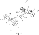
- Fig.1 shows a vehicle 100 to be braked.
- the vehicle 100 may be a battery electric vehicle (BEV) or a hybrid electric vehicle (HEV) comprising a control unit 70 configured to perform a method for braking as shown in Fig. 3 .
- BEV battery electric vehicle
- HEV hybrid electric vehicle
- the vehicle 100 further comprises a first or electric rear axle drive (ERAD) unit 10 and a second or electric front axle drive (EFAD) unit 20.
- Each of the electric rear axle drive (ERAD) unit 10 and the electric front axle drive (EFAD) unit 20 comprises an electric motor unit 11, 21, power electronics (not shown) and a transmission unit (not shown) to allow wheels 12, 22 arranged at each axle drive unit to rotate, wherein the electric motor units 11, 21 may comprise two electric motor for each wheels arranged at the respective axle drive unit 10, 20.
- a battery system 80 is connected to each electric motor unit 11, 21 of the axle drive units 10, 20 to supply power.
- the electric rear axle drive (ERAD) unit 10 or the electric front axle drive (EFAD) unit 20 may be also connected to an internal combustion engine (not shown).
- the wheels 12 arranged at the electric rear axle drive (ERAD) unit 10 are continuously connected during a braking event for recovering a brake energy.
- the wheels 22 arranged at the electric front axle drive (EFAD) unit 20 is connected during the braking event, in case a potential brake energy E to be regenerated is higher than a threshold 40. In other words, if the potential brake energy E to be regenerated is lower than a threshold 40, the brake energy may be recovered only by the electric rear axle drive (ERAD) unit 10.
- the control unit 70 of the vehicle 100 is, hence, configured to determine the threshold 40 indicating, when is worthwhile to connect the wheels 22 to the electric front axle drive (EFAD) unit 20.
- the threshold 40 is determined by summing up a regenerating capacity 31 of the electric rear axle drive (ERAD) unit 10 and a connecting energy 33 required to connecting the wheels 22 to the electric motor unit 21 or shifting the electric front axle drive (EFAD) unit 20 to a regeneration mode.
- the potential brake energy E may be estimated by monitoring an environment of the vehicle 100 affecting the brake event such as a distance between the vehicle 100 and a reference object 200, a speed of the vehicle 100, a relative speed of the vehicle 100 relative to the reference object 200 and/or a mass of the vehicle 100. Monitoring the environment may be performed by a Lidar or radar system or the like.
- the reference object 200 may be a preceding vehicle 200 in a driving direction relative to the vehicle 100 to be braked. If the vehicle 100 to be braked approaches to the preceding vehicle 200 at a low over speed and at an essentially long or adequate braking distance, the electric rear axle drive (ERAD) unit 10 may be able to regenerate the entire brake energy. In other words, the potential brake energy E is lower than the threshold 40 such that the electric rear axle drive (ERAD) unit 10 does not require any additional axle drive unit to regenerate the brake energy.
- the electric rear axle drive (ERAD) unit 10 requires an additional axle drive unit, i.e. the electric front axle drive (EFAD) unit 20, to regenerate the entire brake energy.
- the estimated potential brake energy E is higher than the threshold 40.
- the electric front axle drive (EFAD) unit 20 is switched to the regeneration mode and the wheels arranged at the electric front axle drive (EFAD) unit 20 are connected to the electric motor unit 21 to recover the brake energy.
- Fig. 2c shows, if the vehicle 100 to be braked approaches to the preceding vehicle 200 at a low over speed but at a short braking distance, the potential brake energy E may be also higher than the threshold 40 such that the electric front axle drive (EFAD) unit 20 is switched to the regeneration mode to recover the brake energy.
- EFAD electric front axle drive
- a mechanical brake element 13 of the vehicle 100 may be actuated to perform an urgent braking and a braking capacity 35 of the conventional mechanical brake element 13 may be applied.
- Fig. 3 shows the method for braking a vehicle 100.
- the method comprises, but not necessarily in this order:
- the method further comprises, but not necessarily in this order:
Landscapes
- Engineering & Computer Science (AREA)
- Transportation (AREA)
- Mechanical Engineering (AREA)
- Power Engineering (AREA)
- Sustainable Energy (AREA)
- Electromagnetism (AREA)
- Life Sciences & Earth Sciences (AREA)
- Sustainable Development (AREA)
- Physics & Mathematics (AREA)
- Automation & Control Theory (AREA)
- Chemical & Material Sciences (AREA)
- Combustion & Propulsion (AREA)
- Electric Propulsion And Braking For Vehicles (AREA)
- Valves And Accessory Devices For Braking Systems (AREA)
Abstract
Description
- The present disclosure relates to a method for braking a vehicle, a vehicle comprising a control unit configured to perform such a method and a computer program element for braking a vehicle.
- In a motor vehicle, a brake system is activated to reduce a driving speed of the vehicle. Generally, the traditional brake system comprises a brake disc on a wheel, which produces friction to slow or stop the vehicle. A friction energy generated during braking is converted into a heat energy, which may cause an overheating of the brake system. In contrast, battery electric vehicles or hybrid electric vehicles apply a regenerative brake system to reduce the thermal load on the brake disc and to use a battery system efficiently.
- During regenerative braking, an electric motor acts as an electric generator and converts mechanical energy into electrical energy, which is fed into the battery system. However, enabling the regenerative braking or engaging components of the brake system in a regeneration mode may require an energy.
- There may be a need to provide an improved method for braking a vehicle, which allows a more efficient regeneration of a brake energy.
- The problem is solved by the subject matters of the independent claims of the present disclosure, wherein further embodiments are incorporated in the dependent claims. It should be noted that the aspects of the disclosure described in the following apply to the method for braking a vehicle, a vehicle comprising a control unit configured to perform such a method and a computer program element for braking a vehicle.
- According to the present disclosure, a method for braking a vehicle is presented. The method comprises estimating a potential brake energy to be regenerated during a braking event, determining a threshold based on a regenerating capacity of a first axle drive unit, comparing the potential brake energy to be regenerated with the threshold, and switching a second axle drive unit to a regeneration mode for regenerating the brake energy in case the potential brake energy to be regenerated is higher than the threshold.
- The braking method according to the present disclosure may improve an energy efficiency of the vehicle by timely switching the axle drive units to the regeneration mode in accordance with the estimated potential brake energy. Accordingly, a driving potential of the vehicle and a sustainability of the vehicle may be increased.
- The vehicle may comprise the first axle drive unit and the second axle drive unit, which are primarily configured to supply power to vehicle wheels. The power supply in each axle drive unit may be achieved by an electric machine coupled with a battery system and/or an internal combustion engine. In the regeneration mode of the brake energy, energy may flow in a reverse direction, i.e. from the wheels to the battery system via the electric machine, wherein the electric machine may act as a generator.
- The first axle drive unit may be arranged in a rear side of the vehicle and the second axle drive unit may be arranged in a front side of the vehicle. Alternatively, the first axle drive unit may be arranged in the front side of the vehicle and the second axle drive unit may be arranged in the rear side of the vehicle. The battery system may be a single battery system for both axle drive units or it may comprise two separate battery units, each of which may be connected to each axle drive unit.
- Generally, in battery electric vehicles or hybrid electric vehicles, at least one axle drive unit is continuously connected during a braking event for regenerating a brake energy. However, if the potential brake energy, which may be produced during the braking event, is higher than a threshold determined based on a regenerating capacity of the connected axle drive unit, an excess brake energy may be lost. In other words, if the connected axle drive unit is not able to absorb or regenerate the entire brake energy, the excess brake energy may be wasted in the environment. The term "regenerating capacity" may be understood as an ability of the axle drive unit for regenerating or recovering the brake energy during the braking event, particularly during a limited braking time. The regenerating capacity of the axle drive units may be defined by manufacturer specification.
- In case the potential brake energy is higher than the threshold, the second axle drive unit, which is normally disconnected from the wheels during the braking event, may also be switched to the regeneration mode for regenerating the brake energy. In other words, the second axle drive unit may be connected to the wheels to deliver and recover the brake energy and supply electricity to the battery system.
- Accordingly, a threshold may indicate, when is worthwhile to switch the second axle drive unit to the regeneration mode. A worthwhile moment to switch the second axle drive unit to the regeneration mode may be when the potential brake energy to be regenerated exceeds the threshold determined based on the regenerating capacity of the first axle drive unit.
- In an embodiment, switching the second axle drive unit to a regeneration mode only in case the potential brake energy to be regenerated is higher than the threshold. Hence, the first axle drive unit may be connected to the wheels for regenerating the brake energy only if the estimated potential brake energy, which is able to be regenerated during the braking event, is higher than the threshold comprising the regenerating capacity of the first axle drive unit.
- In an embodiment, determining a threshold based on a regenerating capacity of the first axle drive unit comprises estimating a connecting energy required for switching the second axle drive unit to the regeneration mode. The threshold comprises the regenerating capacity of the first axle drive unit and the connecting energy. The second axle drive unit may consume energy to be shifted in the regeneration mode during the braking event. This energy may be taken into account when estimating the threshold for verifying if it is worthwhile to connect the second axle drive unit for recovering the brake energy. In other words, the threshold may be determined by adding the connecting energy of the second axle drive unit and the regenerating capacity of the first axle drive unit. Hence, only if the potential brake energy is higher than a sum of the connecting energy of the second axle drive unit and the regenerating capacity of the first axle drive unit, the second axle drive unit may be switched in the generation mode.
- In an embodiment, estimating a connecting energy comprises estimating an energy consumption required to connect an electric motor unit arranged at the second axle drive unit to wheels arranged at the second axle drive unit. Generally, a driving energy may be supplied from the battery system to the electric motor unit to actuate the wheels connected to the axle drive unit. However, in the regeneration mode, the electric motor unit may generate an energy caused by a reverse torque applied to wheels to reduce a speed of the vehicle. The recovered energy may be then supplied to the battery system to store it.
- Accordingly, to change an energy flow direction, at least the wheels, the second axle drive unit and the electric motor unit may be switched to the regeneration mode, which may require energy. For example, a clutch member arranged in the second axle drive unit may engage rotating shafts to transfer a kinetic energy to the electric motor unit, which may also require such a connecting energy. Hence, when estimating the connecting energy required for switching the second axle drive unit to the regeneration mode, the energy consumption for connecting the wheels, the second axle drive unit and the electric motor unit in a regeneration mode may be also taken into account.
- In an embodiment, switching a second axle drive unit to a regeneration mode comprises connecting the electric motor unit arranged at the second axle drive unit to the wheels arranged at the second axle drive unit during the braking event. If a control unit of the vehicle verifies that the potential brake energy to be regenerated is higher than the threshold, the wheels, the second axle drive unit and the electric motor unit may be switched to the regeneration mode for allowing a reverse energy flow.
- In an embodiment, switching a second axle drive unit to a regeneration mode comprises connecting a first electric motor and a second electric motor of the electric motor unit arranged at the second axle drive unit to each of the wheels arranged at the second axle drive unit. The electric motor unit arranged at the second axle drive unit may comprise the first electric motor and the second electric motor, each of which is assigned to each wheel arranged at the second axle drive unit. In other words, wheels arranged at the second axle drive unit may comprise an individual electric motor. The battery system may be connected to each of the electric motors to supply power or to recover the brake energy.
- During the braking event, if the potential brake energy is higher than the threshold, the second axle drive unit may be switched to the regeneration mode and the first electric motor and/or the second electric motor may start to regenerate the brake energy and supply regenerated electricity to the battery system. Accordingly, an energy efficiency of the vehicle may be improved.
- In an embodiment, the method further comprises monitoring an environment of the vehicle affecting the brake event. The potential brake energy, which may be regenerated during the braking event, may be influenced by several parameters such as a braking distance, a speed of the vehicle, a mass of the vehicle etc. To estimate a reliable potential brake energy, the environment of the vehicle may be monitored in real-time.
- In an embodiment, monitoring an environment comprises estimating a distance between the vehicle and a reference object, a speed of the vehicle, a relative speed of the vehicle relative to the reference object and/or a mass of the vehicle. The parameters, which may influence a brake energy mainly, are the speed of the vehicle and the mass of the vehicle, by which the kinetic energy may be determined. Additionally, to determine the potential brake energy, which may be regenerated during the braking event, the distance between the vehicle and the reference object, the relative speed of the vehicle relative to the reference object, a driving path and/or weather may be considered.
- In an embodiment, the reference object is a preceding vehicle in a driving direction. In other words, the reference object is a vehicle driving ahead relative to the vehicle to be braked. Additionally or alternatively, the reference object may also be any obstruction on the road or a light signal. The potential brake energy may thus depend on the relative speed of the vehicle to be braked relative to the preceding vehicle and the distance between the vehicle to be braked and the preceding vehicle.
- For example, if the vehicle to be braked approaches to the preceding vehicle or the reference object at a low over speed and at an essentially long or adequate braking distance, the first axle drive unit may not require an additional axle drive unit to regenerate the brake energy. In other words, if the vehicle to be braked drives essentially slightly faster than the preceding vehicle at the essentially long braking distance, the potential brake energy may be lower than the threshold and the second axle drive unit may not be switched to the regeneration mode.
- However, if the vehicle to be braked approaches to the preceding vehicle or the reference object at a high over speed and at an essentially long or adequate braking distance, the first axle drive unit may require an additional axle drive unit to regenerate the entire brake energy. In other words, if the vehicle to be braked drives essentially much faster than the preceding vehicle at the adequate braking distance, the potential brake energy may be higher than the threshold. Hence, the second axle drive unit may be switched to the regeneration mode and the wheels arranged at the second axle drive unit may be connected to the electric motor unit to recover the brake energy.
- Also in case the vehicle to be braked approaches to the preceding vehicle or the reference object at a low over speed but at a short braking distance, the first axle drive unit may require an additional axle drive unit to regenerate the entire brake energy. In other words, if the vehicle to be braked drives essentially slightly faster than the preceding vehicle but at the short braking distance, the potential brake energy may be higher than the threshold. Hence, the second axle drive unit may be switched to the regeneration mode and the wheels arranged at the second axle drive unit may be connected to the electric motor unit to recover the brake energy.
- In an embodiment monitoring is performed by a Lidar system or a radar system. The Lidar (light detection and ranging) system comprises at least one light source and a receiver to measure a distance to a remote target. The light source emits light towards a target, which then scatters the light. Some of the scattered light is received back at the receiver. The system determines the distance to the target based on one or more characteristics associated with the returned light. Whereas the radar system determines a distance to the remote target by measuring a reflection of a high-frequency signal from the target. Additionally or alternatively, an ultrasonic sensor may be also used to measure the distance to the remote target. By applying such distance measuring systems, a precise distance measurement between the vehicle to be braked and the reference object may be achieved and an accurate estimating of the potential brake energy may be performed.
- In an embodiment, the method further comprises actuating a mechanical brake element during the braking event in case the potential brake energy to be regenerated is higher than a sum of the regenerating capacities of the first axle drive unit and the second axle drive unit. In other words, even if both of the first axle drive unit and the second axle drive unit may operate in the regeneration mode, the potential brake energy may be even higher than the sum of the regenerating capacities of them. In such a case, the mechanical brake element such as brake disk may be connected to wheels to mechanically brake the vehicle. This may occur for example, during an urgent braking event.
- In an embodiment, the first axle drive unit is an electric rear axle drive (ERAD) unit and the second axle drive unit is an electric front axle drive (EFAD) unit. The electric axle drive units may comprise an electric motor unit, power electronics and a transmission unit to directly power each axle. Generally, the vehicle comprises one electric axle drive unit in the front side and one electric axle drive unit in the rear sides of the vehicle, wherein the wheels arranged at the electric rear axle drive (ERAD) unit may be continuously connected during the braking event. In contrast, the wheels arranged at the electric front axle drive (EFAD) unit may be connected during the braking event, in case the potential brake energy to be regenerated is higher than the threshold comprising a regenerating capacity of the electric rear axle drive (ERAD) unit and a connecting energy of the electric front axle drive (EFAD) unit with wheels.
- According to the present disclosure, a vehicle is presented. The vehicle comprises a control unit, which is configured to perform
- estimating a potential brake energy to be regenerated during a braking event,
- determining a threshold based on a regenerating capacity of a first axle drive unit,
- comparing the potential brake energy to be regenerated with the threshold, and
- in case the potential brake energy to be regenerated being higher than the threshold, switching a second axle drive unit to a regeneration mode for regenerating the brake energy.
- Accordingly, an energy efficiency of the vehicle may be improved by timely switching the axle drive units to the regeneration mode in accordance with the estimated potential brake energy. In particular, the control unit may determine when is worthwhile to switch the second axle drive unit to the regeneration mode. Hence, a driving potential of the vehicle and a sustainability of the vehicle may be increased.
- In an embodiment, the vehicle is a battery electric vehicle (BEV) or a hybrid electric vehicle (HEV). The control unit may be an engine control unit (ECU) or a separate control unit. The vehicle may further comprise an electric rear axle drive (ERAD) unit and an electric front axle drive (EFAD) unit. Each electric axle drive unit may comprise an electric motor unit, power electronics and a transmission unit to directly power each axle. Generally, the wheels arranged at the electric rear axle drive (ERAD) unit may be continuously connected during the braking event. In contrast, the wheels arranged at the electric front axle drive (EFAD) unit may be connected during the braking event, in case the potential brake energy to be regenerated is higher than the threshold including a regenerating capacity of the electric rear axle drive (ERAD) unit and a connecting energy of the electric front axle drive (EFAD) unit with wheels. Alternatively, the wheels arranged at the electric front axle drive (EFAD) unit may be continuously connected during the braking event, whereas the wheels arranged at the electric rear axle drive (ERAD) unit may be connected during the braking event, in case the potential brake energy to be regenerated is higher than the threshold including a regenerating capacity of the electric front axle drive (EFAD) unit and a connecting energy of the electric rear axle drive (ERAD) unit with wheels.
- According to the present disclosure, also a computer program element is presented. The computer program is configured for braking a vehicle as described above, which, when being executed by a processing element, is adapted to perform the method as described above.
- It should be noted that the above embodiments may be combined with each other irrespective of the aspect involved. Accordingly, the method may be combined with structural features and, likewise, the system may be combined with features described above with regard to the method.
- These and other aspects of the present disclosure will become apparent from and elucidated with reference to the embodiments described hereinafter.
- Exemplary embodiments of the disclosure will be described in the following with reference to the following drawings.
- Fig. 1
- shows schematically and exemplarily an embodiment of a vehicle according to the present disclosure.
- Fig. 2a, 2b, 2c
- show schematically and exemplarily an embodiment of a method for braking a vehicle according to the present disclosure.
- Fig. 3
- shows schematically and exemplarily an embodiment of a method for braking a vehicle according to the present disclosure.
-
Fig.1 shows avehicle 100 to be braked. Thevehicle 100 may be a battery electric vehicle (BEV) or a hybrid electric vehicle (HEV) comprising acontrol unit 70 configured to perform a method for braking as shown inFig. 3 . - The
vehicle 100 further comprises a first or electric rear axle drive (ERAD)unit 10 and a second or electric front axle drive (EFAD)unit 20. Each of the electric rear axle drive (ERAD)unit 10 and the electric front axle drive (EFAD)unit 20 comprises anelectric motor unit wheels electric motor units axle drive unit battery system 80 is connected to eachelectric motor unit axle drive units battery system 80 the electric rear axle drive (ERAD)unit 10 or the electric front axle drive (EFAD)unit 20 may be also connected to an internal combustion engine (not shown). - In general, the
wheels 12 arranged at the electric rear axle drive (ERAD)unit 10 are continuously connected during a braking event for recovering a brake energy. In contrast, thewheels 22 arranged at the electric front axle drive (EFAD)unit 20 is connected during the braking event, in case a potential brake energy E to be regenerated is higher than athreshold 40. In other words, if the potential brake energy E to be regenerated is lower than athreshold 40, the brake energy may be recovered only by the electric rear axle drive (ERAD)unit 10. - The
control unit 70 of thevehicle 100 is, hence, configured to determine thethreshold 40 indicating, when is worthwhile to connect thewheels 22 to the electric front axle drive (EFAD)unit 20. Thethreshold 40 is determined by summing up a regeneratingcapacity 31 of the electric rear axle drive (ERAD)unit 10 and a connectingenergy 33 required to connecting thewheels 22 to theelectric motor unit 21 or shifting the electric front axle drive (EFAD)unit 20 to a regeneration mode. - The potential brake energy E may be estimated by monitoring an environment of the
vehicle 100 affecting the brake event such as a distance between thevehicle 100 and areference object 200, a speed of thevehicle 100, a relative speed of thevehicle 100 relative to thereference object 200 and/or a mass of thevehicle 100. Monitoring the environment may be performed by a Lidar or radar system or the like. - As shown in
Fig. 2a , thereference object 200 may be a precedingvehicle 200 in a driving direction relative to thevehicle 100 to be braked. If thevehicle 100 to be braked approaches to the precedingvehicle 200 at a low over speed and at an essentially long or adequate braking distance, the electric rear axle drive (ERAD)unit 10 may be able to regenerate the entire brake energy. In other words, the potential brake energy E is lower than thethreshold 40 such that the electric rear axle drive (ERAD)unit 10 does not require any additional axle drive unit to regenerate the brake energy. - However, if the
vehicle 100 to be braked approaches to the precedingvehicle 200 or thereference object 200 at a high over speed at an adequate braking distance (seeFig. 2b ), the electric rear axle drive (ERAD)unit 10 requires an additional axle drive unit, i.e. the electric front axle drive (EFAD)unit 20, to regenerate the entire brake energy. In other words, the estimated potential brake energy E is higher than thethreshold 40. Hence, the electric front axle drive (EFAD)unit 20 is switched to the regeneration mode and the wheels arranged at the electric front axle drive (EFAD)unit 20 are connected to theelectric motor unit 21 to recover the brake energy. -
Fig. 2c shows, if thevehicle 100 to be braked approaches to the precedingvehicle 200 at a low over speed but at a short braking distance, the potential brake energy E may be also higher than thethreshold 40 such that the electric front axle drive (EFAD)unit 20 is switched to the regeneration mode to recover the brake energy. - However, in case the potential brake energy E to be regenerated is even higher than a sum of the regenerating
capacities unit 10 and the electric front axle drive (EFAD)unit 20, amechanical brake element 13 of thevehicle 100 may be actuated to perform an urgent braking and abraking capacity 35 of the conventionalmechanical brake element 13 may be applied. -
Fig. 3 shows the method for braking avehicle 100. The method comprises, but not necessarily in this order: - monitoring S1 an environment of the
vehicle 100 affecting the brake event, - monitoring S2 an environment comprising estimating a distance between the
vehicle 100 and areference object 200, a speed of thevehicle 100, a relative speed of thevehicle 100 relative to thereference object 200 and/or a mass of thevehicle 100, - estimating S3 a potential brake energy E to be regenerated during a braking event,
- determining S4 a
threshold 40 based on a regeneratingcapacity 31 of a firstaxle drive unit 10, - comparing S5 the potential brake energy E to be regenerated with the
threshold 40, and - switching S6 a second
axle drive unit 20 to a regeneration mode for regenerating the brake energy, in case the potential brake energy E to be regenerated being higher than thethreshold 40. - The method further comprises, but not necessarily in this order:
- estimating S41 a connecting
energy 33 required for switching the secondaxle drive unit 20 to the regeneration mode, thethreshold 40 comprising the regeneratingcapacity 31 of the firstaxle drive unit 10 and the connectingenergy 33, - estimating S42 an energy consumption required to connect an
electric motor unit 21 arranged at the secondaxle drive unit 20 towheels 22 arranged at the secondaxle drive unit 20, - connecting S61 the
electric motor unit 21 arranged at the secondaxle drive unit 20 to thewheels 22 arranged at the secondaxle drive unit 20 during the braking event, - connecting S62 a first electric motor and a second electric motor of the
electric motor unit 21 arranged at the secondaxle drive unit 20 to each of thewheels 22 arranged at the secondaxle drive unit 20, and - actuating S7 a
mechanical brake element 13 during the braking event in case the potential brake energy E to be regenerated being higher than a sum of the regeneratingcapacities axle drive unit 10 and the secondaxle drive unit 20. - It has to be noted that embodiments of the disclosure are described with reference to different subject matters. In particular, some embodiments are described with reference to method type claims whereas other embodiments are described with reference to the device type claims. However, a person skilled in the art will gather from the above and the following description that, unless otherwise notified, in addition to any combination of features belonging to one type of subject matter also any combination between features relating to different subject matters is considered to be disclosed with this application. However, all features can be combined providing synergetic effects that are more than the simple summation of the features.
- While the disclosure has been illustrated and described in detail in the drawings and description, such illustration and description are to be considered illustrative or exemplary and not restrictive. The disclosure is not limited to the disclosed embodiments. Other variations to the disclosed embodiments can be understood and effected by those skilled in the art in practicing a claimed disclosure, from a study of the drawings, the disclosure, and the dependent claims.
- In the claims, the word "comprising" does not exclude other elements or steps, and the indefinite article "a" or "an" does not exclude a plurality. A single processor or other unit may fulfil the functions of several items re-cited in the claims. The mere fact that certain measures are re-cited in mutually different dependent claims does not indicate that a combination of these measures cannot be used to advantage. Any reference signs in the claims should not be construed as limiting the scope.
Claims (15)
- A method for braking a vehicle (100), comprising:- estimating (S3) a potential brake energy (E) to be regenerated during a braking event,- determining (S4) a threshold (40) based on a regenerating capacity (31) of a first axle drive unit (10),- comparing (S5) the potential brake energy (E) to be regenerated with the threshold (40), and- in case the potential brake energy (E) to be regenerated being higher than the threshold (40), switching (S6) a second axle drive unit (20) to a regeneration mode for regenerating the brake energy.
- The method according to claim 1, switching the second axle drive unit (20) to a regeneration mode only in case the potential brake energy (E) to be regenerated being higher than the threshold (40).
- The method according to claim 1, determining (S4) a threshold (40) based on the regenerating capacity (31) of the first axle drive unit (10) comprising estimating (S41) a connecting energy (33) required for switching the second axle drive unit (20) to the regeneration mode, the threshold (40) comprising the regenerating capacity (31) of the first axle drive unit (10) and the connecting energy (33).
- The method according to claim 3, estimating a connecting energy (33) comprising estimating (S42) an energy consumption required to connect an electric motor unit (21) arranged at the second axle drive unit (20) to wheels (22) arranged at the second axle drive unit (20).
- The method according to claim 4, switching (S6) a second axle drive unit (20) to a regeneration mode comprising connecting (S61) the electric motor unit (21) arranged at the second axle drive unit (20) to the wheels (22) arranged at the second axle drive unit (20) during the braking event.
- The method according to claim 5, switching (S6) a second axle drive unit (20) to a regeneration mode comprising connecting (S62) a first electric motor and a second electric motor of the electric motor unit (21) arranged at the second axle drive unit (20) to each of the wheels (22) arranged at the second axle drive unit (20).
- The method according to any of preceding claims 1 to 6, further comprising monitoring (S1) an environment of the vehicle (100) affecting the brake event.
- The method according to claim 7, monitoring an environment comprising estimating (S2) a distance between the vehicle (100) and a reference object (200), a speed of the vehicle (100), a relative speed of the vehicle (100) relative to the reference object (200) and/or a mass of the vehicle (100).
- The method according to claim 7 or 8, monitoring being performed by a Lidar system or a radar system.
- The method according to claim 8, the reference object (200) being a preceding vehicle (200) in a driving direction.
- The method according to any of the preceding claims 1 to 10, further comprising actuating (S7) a mechanical brake element (13) during the braking event in case the potential brake energy (E) to be regenerated being higher than a sum of the regenerating capacities (31, 32) of the first axle drive unit (10) and the second axle drive unit (20).
- The method according to any of the preceding claims 1 to 11, the first axle drive unit (10) being an electric rear axle drive (ERAD) unit and the second axle drive unit (20) being an electric front axle drive (EFAD) unit (20).
- A vehicle (100) comprising a control unit (70), the control unit (70) being configured to perform- estimating a potential brake energy (E) to be regenerated during a braking event,- determining a threshold (40) based on a regenerating capacity (31) of a first axle drive unit (10),- comparing the potential brake energy (E) to be regenerated with the threshold (40), and- in case the potential brake energy (E) to be regenerated being higher than the threshold (40), switching a second axle drive unit (20) to a regeneration mode for regenerating the brake energy.
- The vehicle (100) according to claim 13 being a battery electric vehicle or a hybrid electric vehicle.
- A computer program element for braking a vehicle (100) according to one of claims 13 and 14, which, when being executed by a processing element, is adapted to perform the method steps of the method claims 1 to 12.
Priority Applications (3)
| Application Number | Priority Date | Filing Date | Title |
|---|---|---|---|
| EP21156421.6A EP4043300B1 (en) | 2021-02-10 | 2021-02-10 | Method for braking a vehicle |
| US17/570,510 US12115883B2 (en) | 2021-02-10 | 2022-01-07 | Method for braking a vehicle |
| CN202210115942.9A CN114905974B (en) | 2021-02-10 | 2022-02-07 | Method for braking a vehicle |
Applications Claiming Priority (1)
| Application Number | Priority Date | Filing Date | Title |
|---|---|---|---|
| EP21156421.6A EP4043300B1 (en) | 2021-02-10 | 2021-02-10 | Method for braking a vehicle |
Publications (2)
| Publication Number | Publication Date |
|---|---|
| EP4043300A1 true EP4043300A1 (en) | 2022-08-17 |
| EP4043300B1 EP4043300B1 (en) | 2023-10-18 |
Family
ID=74595067
Family Applications (1)
| Application Number | Title | Priority Date | Filing Date |
|---|---|---|---|
| EP21156421.6A Active EP4043300B1 (en) | 2021-02-10 | 2021-02-10 | Method for braking a vehicle |
Country Status (3)
| Country | Link |
|---|---|
| US (1) | US12115883B2 (en) |
| EP (1) | EP4043300B1 (en) |
| CN (1) | CN114905974B (en) |
Families Citing this family (1)
| Publication number | Priority date | Publication date | Assignee | Title |
|---|---|---|---|---|
| KR20230083357A (en) * | 2021-12-02 | 2023-06-12 | 현대자동차주식회사 | Method and device for controlling regenerative braking of hybrid vehicle |
Citations (4)
| Publication number | Priority date | Publication date | Assignee | Title |
|---|---|---|---|---|
| US20050264102A1 (en) * | 2004-05-31 | 2005-12-01 | Fuji Jukogyo Kabushiki Kaisha | Vehicle braking system and vehicle braking method |
| US20090145673A1 (en) * | 2007-12-05 | 2009-06-11 | Ford Global Technologies, Llc | Torque Control for Hybrid Electric Vehicle Speed Control Operation |
| GB2508668A (en) * | 2012-12-10 | 2014-06-11 | Jaguar Land Rover Ltd | Adaptive cruise control (ACC) means for a host vehicle having regenerative and non-regenerative braking means |
| GB2545261A (en) * | 2015-12-11 | 2017-06-14 | Jaguar Land Rover Ltd | Control system and method of controlling a driveline |
Family Cites Families (2)
| Publication number | Priority date | Publication date | Assignee | Title |
|---|---|---|---|---|
| US9725880B2 (en) * | 2012-06-08 | 2017-08-08 | Volvo Construction Equipment Ab | Apparatus for controlling a cascaded hybrid construction machine system and a method therefor |
| CN111301175A (en) * | 2020-03-17 | 2020-06-19 | 宁波市江北九方和荣电气有限公司 | Regenerative braking energy feedback system with main control module |
-
2021
- 2021-02-10 EP EP21156421.6A patent/EP4043300B1/en active Active
-
2022
- 2022-01-07 US US17/570,510 patent/US12115883B2/en active Active
- 2022-02-07 CN CN202210115942.9A patent/CN114905974B/en active Active
Patent Citations (4)
| Publication number | Priority date | Publication date | Assignee | Title |
|---|---|---|---|---|
| US20050264102A1 (en) * | 2004-05-31 | 2005-12-01 | Fuji Jukogyo Kabushiki Kaisha | Vehicle braking system and vehicle braking method |
| US20090145673A1 (en) * | 2007-12-05 | 2009-06-11 | Ford Global Technologies, Llc | Torque Control for Hybrid Electric Vehicle Speed Control Operation |
| GB2508668A (en) * | 2012-12-10 | 2014-06-11 | Jaguar Land Rover Ltd | Adaptive cruise control (ACC) means for a host vehicle having regenerative and non-regenerative braking means |
| GB2545261A (en) * | 2015-12-11 | 2017-06-14 | Jaguar Land Rover Ltd | Control system and method of controlling a driveline |
Also Published As
| Publication number | Publication date |
|---|---|
| CN114905974A (en) | 2022-08-16 |
| EP4043300B1 (en) | 2023-10-18 |
| US20220250482A1 (en) | 2022-08-11 |
| CN114905974B (en) | 2025-10-17 |
| US12115883B2 (en) | 2024-10-15 |
Similar Documents
| Publication | Publication Date | Title |
|---|---|---|
| US8768552B2 (en) | Vehicle brake system and method of operating the same | |
| US8116927B2 (en) | Dynamic traction control | |
| US9421962B2 (en) | Method and system for displaying braking information | |
| CN106347137B (en) | Adaptive regenerative braking method and system | |
| CN107697046A (en) | Automatic emergency brake method and system | |
| CN106515506A (en) | System and method for controlling impact reduction of electric vehicle | |
| US11964592B2 (en) | Electric-axle device for commercial vehicle | |
| US10272896B2 (en) | System and method for diagnosing failures in brake systems and discrete vehicle inputs | |
| CN115972917B (en) | Method for performing a brake disc cleaning of a vehicle | |
| US20240042988A1 (en) | Brake assist during vehicle one pedal drive | |
| KR20180025660A (en) | Vehicle having electric motor and method of displaying energy generated by regenerative braking | |
| US12115883B2 (en) | Method for braking a vehicle | |
| KR101048142B1 (en) | Regenerative braking torque control device and method for hybrid vehicle | |
| EP3227136B1 (en) | Electric vehicle moving direction detection | |
| CN110386125B (en) | Method for operating a motor vehicle | |
| US11312240B2 (en) | Hybrid electric vehicle and braking control method thereof | |
| JP2012126288A (en) | Vehicle control device | |
| CN102529706B (en) | Method and apparatus to protect powertrain components from excessive force damage due to wheel lockup | |
| US9878621B2 (en) | System and method for improved ABS performance during parallel regenerative braking | |
| WO2022208527A1 (en) | A braking system for a vehicle | |
| KR20170079022A (en) | The application of Vehicle Decelerate and stop Function by Using Regenerative breaking system for Autonomous Electric Vehicles | |
| US20250388221A1 (en) | Automatic brake control to support propulsion system in electric vehicle | |
| EP4634019A1 (en) | System for controlling braking/traction of an electric or hybrid vehicle | |
| CN118722545A (en) | A control method, device, equipment and medium for automatic emergency braking of a vehicle | |
| GB2633798A (en) | Vehicle brake cleaning during single pedal driving |
Legal Events
| Date | Code | Title | Description |
|---|---|---|---|
| PUAI | Public reference made under article 153(3) epc to a published international application that has entered the european phase |
Free format text: ORIGINAL CODE: 0009012 |
|
| STAA | Information on the status of an ep patent application or granted ep patent |
Free format text: STATUS: REQUEST FOR EXAMINATION WAS MADE |
|
| 17P | Request for examination filed |
Effective date: 20211119 |
|
| AK | Designated contracting states |
Kind code of ref document: A1 Designated state(s): AL AT BE BG CH CY CZ DE DK EE ES FI FR GB GR HR HU IE IS IT LI LT LU LV MC MK MT NL NO PL PT RO RS SE SI SK SM TR |
|
| RIC1 | Information provided on ipc code assigned before grant |
Ipc: B60W 30/18 20120101ALI20230321BHEP Ipc: B60T 1/10 20060101AFI20230321BHEP |
|
| GRAP | Despatch of communication of intention to grant a patent |
Free format text: ORIGINAL CODE: EPIDOSNIGR1 |
|
| STAA | Information on the status of an ep patent application or granted ep patent |
Free format text: STATUS: GRANT OF PATENT IS INTENDED |
|
| INTG | Intention to grant announced |
Effective date: 20230510 |
|
| GRAS | Grant fee paid |
Free format text: ORIGINAL CODE: EPIDOSNIGR3 |
|
| GRAA | (expected) grant |
Free format text: ORIGINAL CODE: 0009210 |
|
| STAA | Information on the status of an ep patent application or granted ep patent |
Free format text: STATUS: THE PATENT HAS BEEN GRANTED |
|
| AK | Designated contracting states |
Kind code of ref document: B1 Designated state(s): AL AT BE BG CH CY CZ DE DK EE ES FI FR GB GR HR HU IE IS IT LI LT LU LV MC MK MT NL NO PL PT RO RS SE SI SK SM TR |
|
| REG | Reference to a national code |
Ref country code: GB Ref legal event code: FG4D |
|
| REG | Reference to a national code |
Ref country code: CH Ref legal event code: EP |
|
| REG | Reference to a national code |
Ref country code: IE Ref legal event code: FG4D |
|
| REG | Reference to a national code |
Ref country code: DE Ref legal event code: R096 Ref document number: 602021005884 Country of ref document: DE |
|
| P01 | Opt-out of the competence of the unified patent court (upc) registered |
Effective date: 20231017 |
|
| REG | Reference to a national code |
Ref country code: LT Ref legal event code: MG9D |
|
| REG | Reference to a national code |
Ref country code: NL Ref legal event code: MP Effective date: 20231018 |
|
| REG | Reference to a national code |
Ref country code: AT Ref legal event code: MK05 Ref document number: 1622182 Country of ref document: AT Kind code of ref document: T Effective date: 20231018 |
|
| PG25 | Lapsed in a contracting state [announced via postgrant information from national office to epo] |
Ref country code: NL Free format text: LAPSE BECAUSE OF FAILURE TO SUBMIT A TRANSLATION OF THE DESCRIPTION OR TO PAY THE FEE WITHIN THE PRESCRIBED TIME-LIMIT Effective date: 20231018 |
|
| PG25 | Lapsed in a contracting state [announced via postgrant information from national office to epo] |
Ref country code: GR Free format text: LAPSE BECAUSE OF FAILURE TO SUBMIT A TRANSLATION OF THE DESCRIPTION OR TO PAY THE FEE WITHIN THE PRESCRIBED TIME-LIMIT Effective date: 20240119 |
|
| PG25 | Lapsed in a contracting state [announced via postgrant information from national office to epo] |
Ref country code: IS Free format text: LAPSE BECAUSE OF FAILURE TO SUBMIT A TRANSLATION OF THE DESCRIPTION OR TO PAY THE FEE WITHIN THE PRESCRIBED TIME-LIMIT Effective date: 20240218 |
|
| PG25 | Lapsed in a contracting state [announced via postgrant information from national office to epo] |
Ref country code: LT Free format text: LAPSE BECAUSE OF FAILURE TO SUBMIT A TRANSLATION OF THE DESCRIPTION OR TO PAY THE FEE WITHIN THE PRESCRIBED TIME-LIMIT Effective date: 20231018 |
|
| PG25 | Lapsed in a contracting state [announced via postgrant information from national office to epo] |
Ref country code: AT Free format text: LAPSE BECAUSE OF FAILURE TO SUBMIT A TRANSLATION OF THE DESCRIPTION OR TO PAY THE FEE WITHIN THE PRESCRIBED TIME-LIMIT Effective date: 20231018 |
|
| PG25 | Lapsed in a contracting state [announced via postgrant information from national office to epo] |
Ref country code: ES Free format text: LAPSE BECAUSE OF FAILURE TO SUBMIT A TRANSLATION OF THE DESCRIPTION OR TO PAY THE FEE WITHIN THE PRESCRIBED TIME-LIMIT Effective date: 20231018 |
|
| PG25 | Lapsed in a contracting state [announced via postgrant information from national office to epo] |
Ref country code: LT Free format text: LAPSE BECAUSE OF FAILURE TO SUBMIT A TRANSLATION OF THE DESCRIPTION OR TO PAY THE FEE WITHIN THE PRESCRIBED TIME-LIMIT Effective date: 20231018 Ref country code: IS Free format text: LAPSE BECAUSE OF FAILURE TO SUBMIT A TRANSLATION OF THE DESCRIPTION OR TO PAY THE FEE WITHIN THE PRESCRIBED TIME-LIMIT Effective date: 20240218 Ref country code: GR Free format text: LAPSE BECAUSE OF FAILURE TO SUBMIT A TRANSLATION OF THE DESCRIPTION OR TO PAY THE FEE WITHIN THE PRESCRIBED TIME-LIMIT Effective date: 20240119 Ref country code: ES Free format text: LAPSE BECAUSE OF FAILURE TO SUBMIT A TRANSLATION OF THE DESCRIPTION OR TO PAY THE FEE WITHIN THE PRESCRIBED TIME-LIMIT Effective date: 20231018 Ref country code: BG Free format text: LAPSE BECAUSE OF FAILURE TO SUBMIT A TRANSLATION OF THE DESCRIPTION OR TO PAY THE FEE WITHIN THE PRESCRIBED TIME-LIMIT Effective date: 20240118 Ref country code: AT Free format text: LAPSE BECAUSE OF FAILURE TO SUBMIT A TRANSLATION OF THE DESCRIPTION OR TO PAY THE FEE WITHIN THE PRESCRIBED TIME-LIMIT Effective date: 20231018 Ref country code: PT Free format text: LAPSE BECAUSE OF FAILURE TO SUBMIT A TRANSLATION OF THE DESCRIPTION OR TO PAY THE FEE WITHIN THE PRESCRIBED TIME-LIMIT Effective date: 20240219 |
|
| PG25 | Lapsed in a contracting state [announced via postgrant information from national office to epo] |
Ref country code: SE Free format text: LAPSE BECAUSE OF FAILURE TO SUBMIT A TRANSLATION OF THE DESCRIPTION OR TO PAY THE FEE WITHIN THE PRESCRIBED TIME-LIMIT Effective date: 20231018 Ref country code: RS Free format text: LAPSE BECAUSE OF FAILURE TO SUBMIT A TRANSLATION OF THE DESCRIPTION OR TO PAY THE FEE WITHIN THE PRESCRIBED TIME-LIMIT Effective date: 20231018 Ref country code: PL Free format text: LAPSE BECAUSE OF FAILURE TO SUBMIT A TRANSLATION OF THE DESCRIPTION OR TO PAY THE FEE WITHIN THE PRESCRIBED TIME-LIMIT Effective date: 20231018 Ref country code: NO Free format text: LAPSE BECAUSE OF FAILURE TO SUBMIT A TRANSLATION OF THE DESCRIPTION OR TO PAY THE FEE WITHIN THE PRESCRIBED TIME-LIMIT Effective date: 20240118 Ref country code: LV Free format text: LAPSE BECAUSE OF FAILURE TO SUBMIT A TRANSLATION OF THE DESCRIPTION OR TO PAY THE FEE WITHIN THE PRESCRIBED TIME-LIMIT Effective date: 20231018 Ref country code: HR Free format text: LAPSE BECAUSE OF FAILURE TO SUBMIT A TRANSLATION OF THE DESCRIPTION OR TO PAY THE FEE WITHIN THE PRESCRIBED TIME-LIMIT Effective date: 20231018 |
|
| PG25 | Lapsed in a contracting state [announced via postgrant information from national office to epo] |
Ref country code: DK Free format text: LAPSE BECAUSE OF FAILURE TO SUBMIT A TRANSLATION OF THE DESCRIPTION OR TO PAY THE FEE WITHIN THE PRESCRIBED TIME-LIMIT Effective date: 20231018 |
|
| REG | Reference to a national code |
Ref country code: DE Ref legal event code: R097 Ref document number: 602021005884 Country of ref document: DE |
|
| PG25 | Lapsed in a contracting state [announced via postgrant information from national office to epo] |
Ref country code: CZ Free format text: LAPSE BECAUSE OF FAILURE TO SUBMIT A TRANSLATION OF THE DESCRIPTION OR TO PAY THE FEE WITHIN THE PRESCRIBED TIME-LIMIT Effective date: 20231018 |
|
| PG25 | Lapsed in a contracting state [announced via postgrant information from national office to epo] |
Ref country code: SK Free format text: LAPSE BECAUSE OF FAILURE TO SUBMIT A TRANSLATION OF THE DESCRIPTION OR TO PAY THE FEE WITHIN THE PRESCRIBED TIME-LIMIT Effective date: 20231018 |
|
| PG25 | Lapsed in a contracting state [announced via postgrant information from national office to epo] |
Ref country code: SM Free format text: LAPSE BECAUSE OF FAILURE TO SUBMIT A TRANSLATION OF THE DESCRIPTION OR TO PAY THE FEE WITHIN THE PRESCRIBED TIME-LIMIT Effective date: 20231018 Ref country code: SK Free format text: LAPSE BECAUSE OF FAILURE TO SUBMIT A TRANSLATION OF THE DESCRIPTION OR TO PAY THE FEE WITHIN THE PRESCRIBED TIME-LIMIT Effective date: 20231018 Ref country code: RO Free format text: LAPSE BECAUSE OF FAILURE TO SUBMIT A TRANSLATION OF THE DESCRIPTION OR TO PAY THE FEE WITHIN THE PRESCRIBED TIME-LIMIT Effective date: 20231018 Ref country code: IT Free format text: LAPSE BECAUSE OF FAILURE TO SUBMIT A TRANSLATION OF THE DESCRIPTION OR TO PAY THE FEE WITHIN THE PRESCRIBED TIME-LIMIT Effective date: 20231018 Ref country code: EE Free format text: LAPSE BECAUSE OF FAILURE TO SUBMIT A TRANSLATION OF THE DESCRIPTION OR TO PAY THE FEE WITHIN THE PRESCRIBED TIME-LIMIT Effective date: 20231018 Ref country code: DK Free format text: LAPSE BECAUSE OF FAILURE TO SUBMIT A TRANSLATION OF THE DESCRIPTION OR TO PAY THE FEE WITHIN THE PRESCRIBED TIME-LIMIT Effective date: 20231018 Ref country code: CZ Free format text: LAPSE BECAUSE OF FAILURE TO SUBMIT A TRANSLATION OF THE DESCRIPTION OR TO PAY THE FEE WITHIN THE PRESCRIBED TIME-LIMIT Effective date: 20231018 |
|
| PLBE | No opposition filed within time limit |
Free format text: ORIGINAL CODE: 0009261 |
|
| STAA | Information on the status of an ep patent application or granted ep patent |
Free format text: STATUS: NO OPPOSITION FILED WITHIN TIME LIMIT |
|
| 26N | No opposition filed |
Effective date: 20240719 |
|
| PG25 | Lapsed in a contracting state [announced via postgrant information from national office to epo] |
Ref country code: MC Free format text: LAPSE BECAUSE OF FAILURE TO SUBMIT A TRANSLATION OF THE DESCRIPTION OR TO PAY THE FEE WITHIN THE PRESCRIBED TIME-LIMIT Effective date: 20231018 |
|
| REG | Reference to a national code |
Ref country code: CH Ref legal event code: PL |
|
| PG25 | Lapsed in a contracting state [announced via postgrant information from national office to epo] |
Ref country code: LU Free format text: LAPSE BECAUSE OF NON-PAYMENT OF DUE FEES Effective date: 20240210 |
|
| PG25 | Lapsed in a contracting state [announced via postgrant information from national office to epo] |
Ref country code: CH Free format text: LAPSE BECAUSE OF NON-PAYMENT OF DUE FEES Effective date: 20240229 |
|
| PG25 | Lapsed in a contracting state [announced via postgrant information from national office to epo] |
Ref country code: SI Free format text: LAPSE BECAUSE OF FAILURE TO SUBMIT A TRANSLATION OF THE DESCRIPTION OR TO PAY THE FEE WITHIN THE PRESCRIBED TIME-LIMIT Effective date: 20231018 |
|
| PG25 | Lapsed in a contracting state [announced via postgrant information from national office to epo] |
Ref country code: SI Free format text: LAPSE BECAUSE OF FAILURE TO SUBMIT A TRANSLATION OF THE DESCRIPTION OR TO PAY THE FEE WITHIN THE PRESCRIBED TIME-LIMIT Effective date: 20231018 Ref country code: LU Free format text: LAPSE BECAUSE OF NON-PAYMENT OF DUE FEES Effective date: 20240210 Ref country code: CH Free format text: LAPSE BECAUSE OF NON-PAYMENT OF DUE FEES Effective date: 20240229 |
|
| REG | Reference to a national code |
Ref country code: BE Ref legal event code: MM Effective date: 20240229 |
|
| PG25 | Lapsed in a contracting state [announced via postgrant information from national office to epo] |
Ref country code: BE Free format text: LAPSE BECAUSE OF NON-PAYMENT OF DUE FEES Effective date: 20240229 |
|
| PG25 | Lapsed in a contracting state [announced via postgrant information from national office to epo] |
Ref country code: IE Free format text: LAPSE BECAUSE OF NON-PAYMENT OF DUE FEES Effective date: 20240210 |
|
| PG25 | Lapsed in a contracting state [announced via postgrant information from national office to epo] |
Ref country code: IE Free format text: LAPSE BECAUSE OF NON-PAYMENT OF DUE FEES Effective date: 20240210 Ref country code: BE Free format text: LAPSE BECAUSE OF NON-PAYMENT OF DUE FEES Effective date: 20240229 |
|
| PG25 | Lapsed in a contracting state [announced via postgrant information from national office to epo] |
Ref country code: CY Free format text: LAPSE BECAUSE OF FAILURE TO SUBMIT A TRANSLATION OF THE DESCRIPTION OR TO PAY THE FEE WITHIN THE PRESCRIBED TIME-LIMIT; INVALID AB INITIO Effective date: 20210210 |
|
| PG25 | Lapsed in a contracting state [announced via postgrant information from national office to epo] |
Ref country code: HU Free format text: LAPSE BECAUSE OF FAILURE TO SUBMIT A TRANSLATION OF THE DESCRIPTION OR TO PAY THE FEE WITHIN THE PRESCRIBED TIME-LIMIT; INVALID AB INITIO Effective date: 20210210 |
|
| PG25 | Lapsed in a contracting state [announced via postgrant information from national office to epo] |
Ref country code: FI Free format text: LAPSE BECAUSE OF FAILURE TO SUBMIT A TRANSLATION OF THE DESCRIPTION OR TO PAY THE FEE WITHIN THE PRESCRIBED TIME-LIMIT Effective date: 20231019 |
|
| PG25 | Lapsed in a contracting state [announced via postgrant information from national office to epo] |
Ref country code: TR Free format text: LAPSE BECAUSE OF FAILURE TO SUBMIT A TRANSLATION OF THE DESCRIPTION OR TO PAY THE FEE WITHIN THE PRESCRIBED TIME-LIMIT Effective date: 20231018 |
|
| PGFP | Annual fee paid to national office [announced via postgrant information from national office to epo] |
Ref country code: GB Payment date: 20260121 Year of fee payment: 6 |
|
| PGFP | Annual fee paid to national office [announced via postgrant information from national office to epo] |
Ref country code: DE Payment date: 20260121 Year of fee payment: 6 |
|
| PGFP | Annual fee paid to national office [announced via postgrant information from national office to epo] |
Ref country code: FR Payment date: 20260121 Year of fee payment: 6 |