EP4043268A1 - Wireless power supply system, power transmission device, and power reception device - Google Patents
Wireless power supply system, power transmission device, and power reception device Download PDFInfo
- Publication number
- EP4043268A1 EP4043268A1 EP20875386.3A EP20875386A EP4043268A1 EP 4043268 A1 EP4043268 A1 EP 4043268A1 EP 20875386 A EP20875386 A EP 20875386A EP 4043268 A1 EP4043268 A1 EP 4043268A1
- Authority
- EP
- European Patent Office
- Prior art keywords
- power
- coil
- road
- power transmission
- wheel
- Prior art date
- Legal status (The legal status is an assumption and is not a legal conclusion. Google has not performed a legal analysis and makes no representation as to the accuracy of the status listed.)
- Pending
Links
Images




Classifications
-
- B—PERFORMING OPERATIONS; TRANSPORTING
- B60—VEHICLES IN GENERAL
- B60L—PROPULSION OF ELECTRICALLY-PROPELLED VEHICLES; SUPPLYING ELECTRIC POWER FOR AUXILIARY EQUIPMENT OF ELECTRICALLY-PROPELLED VEHICLES; ELECTRODYNAMIC BRAKE SYSTEMS FOR VEHICLES IN GENERAL; MAGNETIC SUSPENSION OR LEVITATION FOR VEHICLES; MONITORING OPERATING VARIABLES OF ELECTRICALLY-PROPELLED VEHICLES; ELECTRIC SAFETY DEVICES FOR ELECTRICALLY-PROPELLED VEHICLES
- B60L53/00—Methods of charging batteries, specially adapted for electric vehicles; Charging stations or on-board charging equipment therefor; Exchange of energy storage elements in electric vehicles
- B60L53/10—Methods of charging batteries, specially adapted for electric vehicles; Charging stations or on-board charging equipment therefor; Exchange of energy storage elements in electric vehicles characterised by the energy transfer between the charging station and the vehicle
- B60L53/12—Inductive energy transfer
- B60L53/126—Methods for pairing a vehicle and a charging station, e.g. establishing a one-to-one relation between a wireless power transmitter and a wireless power receiver
-
- H—ELECTRICITY
- H02—GENERATION; CONVERSION OR DISTRIBUTION OF ELECTRIC POWER
- H02J—ELECTRIC POWER NETWORKS; CIRCUIT ARRANGEMENTS OR SYSTEMS FOR SUPPLYING OR DISTRIBUTING ELECTRIC POWER; SYSTEMS FOR STORING ELECTRIC ENERGY
- H02J50/00—Circuit arrangements or systems for wireless supply or distribution of electric power
- H02J50/10—Circuit arrangements or systems for wireless supply or distribution of electric power using inductive coupling
-
- B—PERFORMING OPERATIONS; TRANSPORTING
- B60—VEHICLES IN GENERAL
- B60L—PROPULSION OF ELECTRICALLY-PROPELLED VEHICLES; SUPPLYING ELECTRIC POWER FOR AUXILIARY EQUIPMENT OF ELECTRICALLY-PROPELLED VEHICLES; ELECTRODYNAMIC BRAKE SYSTEMS FOR VEHICLES IN GENERAL; MAGNETIC SUSPENSION OR LEVITATION FOR VEHICLES; MONITORING OPERATING VARIABLES OF ELECTRICALLY-PROPELLED VEHICLES; ELECTRIC SAFETY DEVICES FOR ELECTRICALLY-PROPELLED VEHICLES
- B60L5/00—Current collectors for power supply lines of electrically-propelled vehicles
- B60L5/005—Current collectors for power supply lines of electrically-propelled vehicles without mechanical contact between the collector and the power supply line
-
- B—PERFORMING OPERATIONS; TRANSPORTING
- B60—VEHICLES IN GENERAL
- B60L—PROPULSION OF ELECTRICALLY-PROPELLED VEHICLES; SUPPLYING ELECTRIC POWER FOR AUXILIARY EQUIPMENT OF ELECTRICALLY-PROPELLED VEHICLES; ELECTRODYNAMIC BRAKE SYSTEMS FOR VEHICLES IN GENERAL; MAGNETIC SUSPENSION OR LEVITATION FOR VEHICLES; MONITORING OPERATING VARIABLES OF ELECTRICALLY-PROPELLED VEHICLES; ELECTRIC SAFETY DEVICES FOR ELECTRICALLY-PROPELLED VEHICLES
- B60L53/00—Methods of charging batteries, specially adapted for electric vehicles; Charging stations or on-board charging equipment therefor; Exchange of energy storage elements in electric vehicles
- B60L53/10—Methods of charging batteries, specially adapted for electric vehicles; Charging stations or on-board charging equipment therefor; Exchange of energy storage elements in electric vehicles characterised by the energy transfer between the charging station and the vehicle
- B60L53/12—Inductive energy transfer
-
- B—PERFORMING OPERATIONS; TRANSPORTING
- B60—VEHICLES IN GENERAL
- B60L—PROPULSION OF ELECTRICALLY-PROPELLED VEHICLES; SUPPLYING ELECTRIC POWER FOR AUXILIARY EQUIPMENT OF ELECTRICALLY-PROPELLED VEHICLES; ELECTRODYNAMIC BRAKE SYSTEMS FOR VEHICLES IN GENERAL; MAGNETIC SUSPENSION OR LEVITATION FOR VEHICLES; MONITORING OPERATING VARIABLES OF ELECTRICALLY-PROPELLED VEHICLES; ELECTRIC SAFETY DEVICES FOR ELECTRICALLY-PROPELLED VEHICLES
- B60L53/00—Methods of charging batteries, specially adapted for electric vehicles; Charging stations or on-board charging equipment therefor; Exchange of energy storage elements in electric vehicles
- B60L53/10—Methods of charging batteries, specially adapted for electric vehicles; Charging stations or on-board charging equipment therefor; Exchange of energy storage elements in electric vehicles characterised by the energy transfer between the charging station and the vehicle
- B60L53/12—Inductive energy transfer
- B60L53/124—Detection or removal of foreign bodies
-
- B—PERFORMING OPERATIONS; TRANSPORTING
- B60—VEHICLES IN GENERAL
- B60L—PROPULSION OF ELECTRICALLY-PROPELLED VEHICLES; SUPPLYING ELECTRIC POWER FOR AUXILIARY EQUIPMENT OF ELECTRICALLY-PROPELLED VEHICLES; ELECTRODYNAMIC BRAKE SYSTEMS FOR VEHICLES IN GENERAL; MAGNETIC SUSPENSION OR LEVITATION FOR VEHICLES; MONITORING OPERATING VARIABLES OF ELECTRICALLY-PROPELLED VEHICLES; ELECTRIC SAFETY DEVICES FOR ELECTRICALLY-PROPELLED VEHICLES
- B60L53/00—Methods of charging batteries, specially adapted for electric vehicles; Charging stations or on-board charging equipment therefor; Exchange of energy storage elements in electric vehicles
- B60L53/30—Constructional details of charging stations
- B60L53/32—Constructional details of charging stations by charging in short intervals along the itinerary, e.g. during short stops
-
- B—PERFORMING OPERATIONS; TRANSPORTING
- B60—VEHICLES IN GENERAL
- B60L—PROPULSION OF ELECTRICALLY-PROPELLED VEHICLES; SUPPLYING ELECTRIC POWER FOR AUXILIARY EQUIPMENT OF ELECTRICALLY-PROPELLED VEHICLES; ELECTRODYNAMIC BRAKE SYSTEMS FOR VEHICLES IN GENERAL; MAGNETIC SUSPENSION OR LEVITATION FOR VEHICLES; MONITORING OPERATING VARIABLES OF ELECTRICALLY-PROPELLED VEHICLES; ELECTRIC SAFETY DEVICES FOR ELECTRICALLY-PROPELLED VEHICLES
- B60L53/00—Methods of charging batteries, specially adapted for electric vehicles; Charging stations or on-board charging equipment therefor; Exchange of energy storage elements in electric vehicles
- B60L53/30—Constructional details of charging stations
- B60L53/35—Means for automatic or assisted adjustment of the relative position of charging devices and vehicles
- B60L53/38—Means for automatic or assisted adjustment of the relative position of charging devices and vehicles specially adapted for charging by inductive energy transfer
-
- B—PERFORMING OPERATIONS; TRANSPORTING
- B60—VEHICLES IN GENERAL
- B60L—PROPULSION OF ELECTRICALLY-PROPELLED VEHICLES; SUPPLYING ELECTRIC POWER FOR AUXILIARY EQUIPMENT OF ELECTRICALLY-PROPELLED VEHICLES; ELECTRODYNAMIC BRAKE SYSTEMS FOR VEHICLES IN GENERAL; MAGNETIC SUSPENSION OR LEVITATION FOR VEHICLES; MONITORING OPERATING VARIABLES OF ELECTRICALLY-PROPELLED VEHICLES; ELECTRIC SAFETY DEVICES FOR ELECTRICALLY-PROPELLED VEHICLES
- B60L9/00—Electric propulsion with power supply external to the vehicle
-
- H—ELECTRICITY
- H02—GENERATION; CONVERSION OR DISTRIBUTION OF ELECTRIC POWER
- H02J—ELECTRIC POWER NETWORKS; CIRCUIT ARRANGEMENTS OR SYSTEMS FOR SUPPLYING OR DISTRIBUTING ELECTRIC POWER; SYSTEMS FOR STORING ELECTRIC ENERGY
- H02J50/00—Circuit arrangements or systems for wireless supply or distribution of electric power
- H02J50/005—Mechanical details of housing or structure aiming to accommodate the power transfer means, e.g. mechanical integration of coils, antennas or transducers into emitting or receiving devices
-
- H—ELECTRICITY
- H02—GENERATION; CONVERSION OR DISTRIBUTION OF ELECTRIC POWER
- H02J—ELECTRIC POWER NETWORKS; CIRCUIT ARRANGEMENTS OR SYSTEMS FOR SUPPLYING OR DISTRIBUTING ELECTRIC POWER; SYSTEMS FOR STORING ELECTRIC ENERGY
- H02J50/00—Circuit arrangements or systems for wireless supply or distribution of electric power
- H02J50/40—Circuit arrangements or systems for wireless supply or distribution of electric power using two or more transmitting or receiving devices
-
- H—ELECTRICITY
- H02—GENERATION; CONVERSION OR DISTRIBUTION OF ELECTRIC POWER
- H02J—ELECTRIC POWER NETWORKS; CIRCUIT ARRANGEMENTS OR SYSTEMS FOR SUPPLYING OR DISTRIBUTING ELECTRIC POWER; SYSTEMS FOR STORING ELECTRIC ENERGY
- H02J50/00—Circuit arrangements or systems for wireless supply or distribution of electric power
- H02J50/60—Circuit arrangements or systems for wireless supply or distribution of electric power responsive to the presence of foreign objects, e.g. detection of living beings
-
- B—PERFORMING OPERATIONS; TRANSPORTING
- B60—VEHICLES IN GENERAL
- B60M—POWER SUPPLY LINES, AND DEVICES ALONG RAILS, FOR ELECTRICALLY- PROPELLED VEHICLES
- B60M7/00—Power lines or rails specially adapted for electrically-propelled vehicles of special types, e.g. suspension tramway, ropeway, underground railway
-
- H—ELECTRICITY
- H02—GENERATION; CONVERSION OR DISTRIBUTION OF ELECTRIC POWER
- H02J—ELECTRIC POWER NETWORKS; CIRCUIT ARRANGEMENTS OR SYSTEMS FOR SUPPLYING OR DISTRIBUTING ELECTRIC POWER; SYSTEMS FOR STORING ELECTRIC ENERGY
- H02J2105/00—Networks for supplying or distributing electric power characterised by their spatial reach or by the load
- H02J2105/30—Networks for supplying or distributing electric power characterised by their spatial reach or by the load the load networks being external to vehicles, i.e. exchanging power with vehicles
- H02J2105/33—Networks for supplying or distributing electric power characterised by their spatial reach or by the load the load networks being external to vehicles, i.e. exchanging power with vehicles exchanging power with road vehicles
- H02J2105/37—Networks for supplying or distributing electric power characterised by their spatial reach or by the load the load networks being external to vehicles, i.e. exchanging power with vehicles exchanging power with road vehicles exchanging power with electric vehicles [EV] or with hybrid electric vehicles [HEV]
-
- Y—GENERAL TAGGING OF NEW TECHNOLOGICAL DEVELOPMENTS; GENERAL TAGGING OF CROSS-SECTIONAL TECHNOLOGIES SPANNING OVER SEVERAL SECTIONS OF THE IPC; TECHNICAL SUBJECTS COVERED BY FORMER USPC CROSS-REFERENCE ART COLLECTIONS [XRACs] AND DIGESTS
- Y02—TECHNOLOGIES OR APPLICATIONS FOR MITIGATION OR ADAPTATION AGAINST CLIMATE CHANGE
- Y02T—CLIMATE CHANGE MITIGATION TECHNOLOGIES RELATED TO TRANSPORTATION
- Y02T10/00—Road transport of goods or passengers
- Y02T10/60—Other road transportation technologies with climate change mitigation effect
- Y02T10/70—Energy storage systems for electromobility, e.g. batteries
-
- Y—GENERAL TAGGING OF NEW TECHNOLOGICAL DEVELOPMENTS; GENERAL TAGGING OF CROSS-SECTIONAL TECHNOLOGIES SPANNING OVER SEVERAL SECTIONS OF THE IPC; TECHNICAL SUBJECTS COVERED BY FORMER USPC CROSS-REFERENCE ART COLLECTIONS [XRACs] AND DIGESTS
- Y02—TECHNOLOGIES OR APPLICATIONS FOR MITIGATION OR ADAPTATION AGAINST CLIMATE CHANGE
- Y02T—CLIMATE CHANGE MITIGATION TECHNOLOGIES RELATED TO TRANSPORTATION
- Y02T10/00—Road transport of goods or passengers
- Y02T10/60—Other road transportation technologies with climate change mitigation effect
- Y02T10/7072—Electromobility specific charging systems or methods for batteries, ultracapacitors, supercapacitors or double-layer capacitors
-
- Y—GENERAL TAGGING OF NEW TECHNOLOGICAL DEVELOPMENTS; GENERAL TAGGING OF CROSS-SECTIONAL TECHNOLOGIES SPANNING OVER SEVERAL SECTIONS OF THE IPC; TECHNICAL SUBJECTS COVERED BY FORMER USPC CROSS-REFERENCE ART COLLECTIONS [XRACs] AND DIGESTS
- Y02—TECHNOLOGIES OR APPLICATIONS FOR MITIGATION OR ADAPTATION AGAINST CLIMATE CHANGE
- Y02T—CLIMATE CHANGE MITIGATION TECHNOLOGIES RELATED TO TRANSPORTATION
- Y02T90/00—Enabling technologies or technologies with a potential or indirect contribution to GHG emissions mitigation
- Y02T90/10—Technologies relating to charging of electric vehicles
- Y02T90/14—Plug-in electric vehicles
-
- Y—GENERAL TAGGING OF NEW TECHNOLOGICAL DEVELOPMENTS; GENERAL TAGGING OF CROSS-SECTIONAL TECHNOLOGIES SPANNING OVER SEVERAL SECTIONS OF THE IPC; TECHNICAL SUBJECTS COVERED BY FORMER USPC CROSS-REFERENCE ART COLLECTIONS [XRACs] AND DIGESTS
- Y02—TECHNOLOGIES OR APPLICATIONS FOR MITIGATION OR ADAPTATION AGAINST CLIMATE CHANGE
- Y02T—CLIMATE CHANGE MITIGATION TECHNOLOGIES RELATED TO TRANSPORTATION
- Y02T90/00—Enabling technologies or technologies with a potential or indirect contribution to GHG emissions mitigation
- Y02T90/10—Technologies relating to charging of electric vehicles
- Y02T90/16—Information or communication technologies improving the operation of electric vehicles
Definitions
- the present disclosure relates to a wireless power transfer system, a power transmission device, and a power reception device.
- a wireless power transfer technology in which a power transmission device provided in a road surface such as a road supplies power wirelessly to a power reception device installed in a vehicle.
- PTL 1 discloses a vehicle provided with a power reception device on the underside of the vehicle, which enables the vehicle to receive power from a power transmission device provided in a road surface.
- the wireless power transfer technology of the related art if the power transmission device provided in a road surface such as a road and the power reception device installed in a moving body that travels on the road are too far apart, an obstacle such as a small animal or piece of metal may come into the space between the power transmission device and the power reception device, eddy currents may be generated around the obstacle, and the power transfer efficiency may be lowered. Moreover, the small animal, piece of metal, or the like that has come between the power transmission device and the power reception device may heat up and catch fire. For this reason, there is a demand for further improvement in the usefulness of wireless power transfer technology for supplying power wirelessly to a moving body.
- a purpose of the present disclosure devised in the light of such circumstances is to provide a wireless power transfer system, a power transmission device, and a power reception device with which the usefulness of wireless power transfer can be improved.
- a wireless power transfer system comprises:
- a power transmission device is provided with a power transmission coil that transmits power wirelessly, and is configured such that when installed in a road, the normal line of the coil plane of the power transmission coil is inclined with respect to the normal line of the road surface of the road in a lateral cross section of the road.
- a power reception device is provided with a power reception coil that receives power wirelessly, and is configured such that in the state in which at least a portion of the power reception coil is housed in a wheel of a moving body, the normal line of the coil plane of the power reception coil is inclined with respect to the normal line of a contact patch of the wheel with the road surface in a lateral cross section of the moving body.
- the lateral direction of a wheel refers to the direction parallel to the rotation axis of the wheel.
- the radial direction of a wheel refers to the direction orthogonal to the rotation axis of the wheel.
- the extension direction of a road or traffic lane refers to the direction in which the road or traffic lane extends.
- the lateral direction of a road or traffic lane refers to the direction orthogonal to the extension direction.
- the lateral direction of a moving body refers to the direction orthogonal to the direction in which the moving body travels.
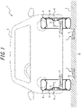
- FIGS. 1 and 2 will be referenced to describe a configuration of a wireless power transfer system 1 according to an embodiment of the present disclosure.
- FIG. 1 illustrates a schematic diagram that uses a lateral cross section of wheels 6 of a moving body 5 to generally illustrate the wireless power transfer system 1 according to an embodiment of the present disclosure.
- the wireless power transfer system 1 includes a power transmission device 2 and a power reception device 3.
- the power transmission device 2 is installed in a road 4.
- the power reception device 3 is installed in a moving body 5. With this arrangement, in the wireless power transfer system 1, power is transmitted wirelessly from the power transmission device 2 to the power reception device 3 when the moving body 5 travels on the road 4 in the extension direction of the road 4.
- the power transmission device 2 is provided with a power transmission coil 21.
- the power transmission coil 21 transmits power wirelessly through the power transmission coil 21.
- the power transmission coil 21 is positioned lower than the road surface of the road 4 in the direction perpendicular to the road surface. Specifically, the power transmission coil 21 is embedded below the road surface of the road 4. In the present embodiment, the power transmission coil 21 is embedded below the road surface of the road 4 such that at least a portion of the power transmission coil 21 is exposed on the road surface of the road 4. In FIG. 1 , the power transmission coil 21 is illustrated schematically for simplicity.
- the power reception device 3 is provided with a power reception coil 31.
- the power reception coil 31 receives power transmitted wirelessly from the power transmission coil 21 of the power transmission device 2.
- the power reception device 3 is installed in a moving body 5.
- at least a portion of the power reception coil 31 of the power reception device 3 is housed in the wheel 6 of the moving body 5.
- the power reception device 3 is attached to the wheel 6 of the moving body 5 such that at least a portion of the power reception coil 31 is housed in the wheel 6 of the moving body 5.
- the power reception device 3 may also be attached to the main body of the moving body 5 such that at least a portion of the power reception coil 31 is housed in the wheel 6 of the moving body 5.
- the power reception coil 31 is illustrated schematically for simplicity.
- the road 4 has a road surface used for transportation by the moving body 5.
- the "road surface” is the surface of the road 4 on which the moving body 5 travels by the wheel 6.
- the road 4 is a street.
- the road 4 is not limited to a street and may also include a walkway, a farm road, a forest road, a runway, a parking lot, a vacant lot, or an open space, for example.
- Transportation by the moving body 5 includes the driving, stopping, and parking of the moving body 5.
- At least one traffic lane 41 may be provided on the road surface of the road 4.
- the traffic lane 41 is an area of the road surface demarcated as an area in which the moving body 5 travels.
- the road 4 may also be provided with a plurality of traffic lanes 41 according to the number of moving bodies 5 that can travel alongside each other.
- the road surface of the road 4 may be painted with demarcation lines such as white lines to indicate the traffic lane 41.
- the road surface of the road 4 is paved with asphalt, for example.
- the road surface of the road 4 is not limited to asphalt and may also be configured using a material such as concrete, stone, brick, dirt, and sand.
- the moving body 5 travels over the road surface of the road 4 by the wheel 6.
- the moving body 5 is an automobile that includes a motor as a source of motive power, such as an electric vehicle or a hybrid vehicle, for example.
- the automobile is a vehicle such as a passenger vehicle, a truck, a bus, and a motorcycle.
- the moving body 5 is not limited to an automobile, and may also be an agricultural vehicle such as a tractor, an industrial or construction vehicle such as a dump truck, an aircraft, a helicopter, a motorized bicycle, an electric bicycle, an electric wheelchair, and the like.
- the wheel 6 is used to move the moving body 5.
- the wheel 6 has a contact patch that contacts the road surface of the road 4 while attached to the moving body 5.
- the wheel 6 is a tire and wheel assembly obtained by mounting a tire 61 onto a wheel 62, but is not limited thereto.
- the "contact patch" of the wheel 6 refers to the contact patch of the tire 61, or in other words, the surface of the tire 61 that touches the road surface in the state in which the tire 61 is mounted onto an applicable rim, inflated to a prescribed internal pressure, and subjected to a maximum load.
- an "applicable rim” refers to a valid industrial standard in the region where a pneumatic tire is manufactured and used, namely, an approved rim for an applicable size described in a publication such as the JATMA Year Book of the Japan Automobile Tyre Manufacturers Association (JATMA) in Japan, the Standards Manual of the European Tyre and Rim Technical Organization (ETRTO) in Europe, or the Year Book of the Tire and Rim Association, Inc.
- JATMA Year Book of the Japan Automobile Tyre Manufacturers Association JATMA Year Book of the Japan Automobile Tyre Manufacturers Association (JATMA) in Japan, the Standards Manual of the European Tyre and Rim Technical Organization (ETRTO) in Europe, or the Year Book of the Tire and Rim Association, Inc.
- the applicable rim refers to a rim of a width corresponding to the bead width of the pneumatic tire.
- the "applicable rim” includes sizes that may be included in the above industrial standards in the future in addition to current sizes.
- the “sizes to be described in the future” may include the sizes described as "Future Developments” in the ETRTO 2013 edition, for example.
- the "prescribed internal pressure” refers to the air pressure (maximum air pressure) corresponding to the maximum load capability of a single wheel for the applicable size and ply rating described in an industrial standard such as the JATMA Year Book described above, but in the case of a size not described in the above industrial standards, the prescribed internal pressure refers to the air pressure (maximum air pressure) corresponding to the maximum load capability prescribed for each vehicle on which the tires are mounted.
- the "maximum load” refers to the load corresponding to the maximum load capability for a tire of applicable size described in the above industrial standards, or in the case of a size not described in the above industrial standards, the load corresponding to the maximum load capability prescribed for each vehicle on which the tires are mounted.
- FIG. 2 illustrates a schematic diagram that uses a lateral cross section of the wheel 6 to generally illustrate a tire and wheel assembly as one example of the wheel 6 in the wireless power transfer system 1 according to an embodiment of the present disclosure.
- the tire 61 includes a pair of bead portions 611, a pair of sidewall portions 612, and a tread portion 613.
- the bead portions 611 are configured such that the inner radial side and outer lateral side of the bead portions 611 touch a rim portion 621 of the wheel 62 when the tire 61 is mounted onto the rim portion 621.
- the sidewall portions 612 extend between the tread portion 613 and the bead portions 611.
- the sidewall portions 612 are positioned farther outward than the bead portions 611 in the radial direction of the wheel 6.
- the tread portion 613 is positioned farther outward than the sidewall portions 312 in the radial direction of the wheel 6, and includes the contact patch of the tire 61.
- the tire 61 is formed using a rubber such as natural rubber and synthetic rubber, and may include parts such as a carcass, a belt, and bead wires formed using a metal such as steel.
- a metal such as steel
- at least a portion of the parts such as the carcass, belt, and bead wires may also be formed using a nonmagnetic material.
- the strength of the tire 61 can be maintained, while in addition, due to the existence of a metal between the power transmission device 2 and the power reception device 3, the tire 61 can lessen the attenuation of a magnetic field generated by the power transmission coil 21 before the magnetic field reaches the power reception coil 31, and by extension, improve the power transfer efficiency of the wireless power transfer from the power transmission device 2 to the power reception device 3.
- at least a portion of the parts such as the carcass, belt, and bead wires does not have to be formed using a nonmagnetic material.
- the nonmagnetic material may include a paramagnetic material or a diamagnetic material having a low permeability.
- a resin material containing a thermoplastic resin such as polyester and nylon, a thermosetting resin such as a vinyl ester resin and an unsaturated polyester resin, and some other synthetic resin can be used as the nonmagnetic material.
- fibers of a material such as glass, carbon, graphite, aramid, polyethylene, and ceramic can be included in the resin material as reinforcing fibers.
- the nonmagnetic material is not limited to a resin, and any nonmetallic material containing rubber, glass, carbon, graphite, aramid, polyethylene, ceramic, and the like can be used.
- a metal material containing a paramagnetic material such as aluminum or a diamagnetic material such as copper can be used as the nonmagnetic material.
- the wheel 62 includes a cylindrical rim portion 621 for mounting the tire 61, hub portion 622 which is provided in the inner radial side of the rim portion 621 and which is secured to a shaft 52 of the moving body 5, and a disc portion 623 which is supported by and secured to the hub portion 622 and also supports and secures the rim portion 621.
- the wheel 62 may be formed using a metal such as steel, but is not limited thereto. At least a portion of the rim portion 621, the hub portion 622, and the disc portion 623 of the wheel 62 may be formed using the nonmagnetic material described above. With this configuration, the strength of the wheel 62 can be maintained, while in addition, due to the existence of a metal such as steel between the power transmission device 2 and the power reception device 3, the wheel 62 can lessen the attenuation of a magnetic field generated by the power transmission coil 21 before the magnetic field reaches the power reception coil 31, and by extension, improve the power transfer efficiency of the wireless power transfer from the power transmission device 2 to the power reception device 3. However, at least a portion of the rim portion 621, the hub portion 622, and the disc portion 623 of the wheel 62 does not have to be formed using a nonmagnetic material.
- the power reception device 3 is attached to the hub portion 622 of the wheel 62.
- at least a portion of the power reception coil 31 is housed in the wheel 6.
- "Housed in the wheel” means being disposed farther inward than the lateral sides of the wheel, on the inner radial side from the outer circumferential surface of the wheel. In the present embodiment, the majority of the power reception coil 31 is housed in the wheel 6.
- the power reception device 3 is disposed in a location of the wheel 6 that does not rotate in association with the rotation of the wheel 6 such as a cover of the hub portion 622 of the wheel 62. With this arrangement, the relative position of the power reception coil 31 inside the wheel 6 does not change depending on the rotation of the tire 61, thereby making it easy to provide a stable supply of power to the power reception device 3 wirelessly from outside the wheel 6.
- the ratio of the portion of the power reception coil 31 housed in the wheel 6 of the moving body 5 relative to the whole may be determined in any way.
- a higher ratio of the portion of the power reception coil 31 housed in the wheel 6 relative to the whole means that an obstacle will not come into the space between the power transmission coil 21 and the power reception coil 31 as easily when transferring power from the power transmission coil 21.
- a lower ratio of the portion of the power reception coil 31 housed in the wheel 6 relative to the whole means that the magnetic field generated by the power transmission coil 21 will not attenuate as much before reaching the power reception coil 31 when transferring power from the power transmission coil 21.
- the power reception device 3 is not limited to the hub portion 622 of the wheel 62, and may be installed at any location in the wheel 6.
- the power reception device 3 may also be installed on the inner circumferential surface of the rim portion 621 or the outer circumferential surface of the rim portion 621 of the wheel 62.
- the power reception device 3 may also be installed on the inner circumferential surface of the tread portion 613 of the tire 61, or inside the tread portion 613 of the tire 61.
- FIGS. 3 and 4 will be referenced to describe a configuration of the power transmission device 2 included in the wireless power transfer system 1 according to an embodiment of the present disclosure.
- FIG. 3 illustrates a function block diagram schematically illustrating a configuration example of the power transmission device 2 according to an embodiment of the present disclosure.
- the power transmission device 2 is provided with a power converter 22, a power storage unit 23, a detector 24, a communication unit 25, a storage unit 26, and a controller 27 in addition to the power transmission coil 21.
- the power transmission coil 21, the power converter 22, the power storage unit 23, the detector 24, the communication unit 25, the storage unit 26, and the controller 27 are communicably interconnected in a wired or wireless way over a network such as a local area network (LAN), for example.
- LAN local area network
- the power transmission coil 21 generates an AC magnetic field.
- the power transmission coil 21 is configured into a loop overall.
- the plane enclosed by the looped power transmission coil 21 is also referred to as the coil plane S1 of the power transmission coil 21.
- the power transmission coil 21 is wound in the in-plane direction of the coil plane S1 to form the coil plane S1.
- the power transmission coil 21 can generate an AC magnetic field pointing in the direction perpendicular to the power transmission coil 21, or in other words, pointing in the direction in which the normal line of the coil plane S1 extends.
- FIG. 4 illustrates a schematic diagram that uses a lateral cross section of a road to generally illustrate the coil plane S1 and inclination of the power transmission coil 21 provided in the power transmission device 2 according to an embodiment of the present disclosure.
- the power transmission device 2 is configured such that when installed in the road 4, the normal line of the coil plane S1 of the power transmission coil 21 is inclined with respect to the normal line of the road surface in a lateral cross section of the road 4.
- the coil plane S1 of the power transmission coil 21 is inclined with respect to the road surface in a lateral cross section of the road 4.
- the power transmission coil 21 is supported by and secured to a housing of the power transmission device 2 through a supporting member 211 such that the normal line V of the coil plane S1 has an inclination ⁇ 1 with respect to the normal line of the road surface in a lateral cross section of the road 4.
- the inclination ⁇ 1 may be set to any angle within a range whereby the normal line of the coil plane S1 of the power transmission coil 21 is not parallel to the normal line of the road surface.
- At least a portion of the supporting member 211 and the housing of the power transmission device 2 may be formed using the nonmagnetic material described above. With this configuration, the magnetic field generated by the power transmission coil 21 is not attenuated as easily when passing through the supporting member 211 and the housing of the power transmission device 2.
- the power converter 22 is connected to the power transmission coil 21.
- the power converter 22 includes an AC/DC converter and an inverter, for example.
- the power converter 22 converts power transmitted from a power source P outside the power transmission device 2 or from the power storage unit 23, and transmits the power to the power transmission coil 21.
- the power storage unit 23 is connected to the power converter 22.
- the power storage unit 23 includes a storage battery that can charge and discharge power, such as a lead storage battery, a nickel-metal hydride battery, a lithium-ion battery, and a sodium-sulfur battery, for example.
- the power storage unit 23 is not limited to a storage battery and may also include a capacitor or the like.
- the power storage unit 23 stores power transmitted from the power source P or transmits power to the power transmission coil 21 through the power converter 22.
- the detector 24 includes a sensor such as an infrared sensor, an image sensor, a motion sensor, and a pressure sensor, for example.
- the detector 24 detects a state in which the power reception device 3 exists at a position where power can be received from the power transmission device 2.
- the communication unit 25 includes one or more communication modules.
- the communication module(s) may be a wired LAN communication module, a wireless LAN communication module, or a controller area network (CAN) communication module, for example.
- the communication unit 25 achieves communication with an external computer or the like over a network such as the Internet.
- the storage unit 26 is a memory such as semiconductor memory, magnetic memory, or optical memory, for example.
- the storage unit 26 functions as main memory, auxiliary memory, or cache memory, for example.
- the storage unit 26 stores information of any type used in the operation of the power transmission device 2.
- the storage unit 26 stores a system program, an application program, embedded software, and the like.
- the controller 27 includes one or more processors.
- the processor(s) may be a general-purpose processor such as a central processing unit (CPU) or a dedicated processor specialized for a specific task, for example.
- the controller 27 is not limited to a processor and may also include one or more dedicated circuits.
- the dedicated circuit(s) may be a field-programmable gate array (FPGA) or an application-specific integrated circuit (ASIC), for example.
- the controller 27 controls the power transmission coil 21, power converter 22, power storage unit 23, detector 24, communication unit 25, and storage unit 26 described above to achieve the functions of the power transmission device 2.
- the controller 27 can determine whether or not the power reception device 3 exists at a position where power can be received from the power transmission device 2. Specifically, the controller 27 detects the power reception device 3 with the detector 24, and thereby determines that the power reception device 3 exists at a position where power can be received from the power transmission device 2. The controller 27 may also detect the moving body 5 or the wheel 6 with the detector 24, and thereby indirectly determine that the power reception device 3 exists at a position where power can be received from the power transmission device 2. Alternatively, the controller 27 may acquire information indicating that the power reception device 3 exists at a position where power can be received from the power transmission device 2 from the power reception device 3 or an external computer through the communication unit 25.
- the controller 27 can transmit power wirelessly. Specifically, the controller 27 can control at least one of the power transmission coil 21, the power converter 22, and the power storage unit 23 to generate an AC magnetic field pointing in the direction in which the normal line of the coil plane S1 of the power transmission coil 21 extends.
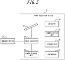
- FIGS. 5 and 6 will be referenced to describe a configuration of the power reception device 3 included in the wireless power transfer system 1 according to an embodiment of the present disclosure.
- FIG. 5 illustrates a function block diagram schematically illustrating a configuration example of the power reception device 3 according to an embodiment of the present disclosure.
- the power reception device 3 is provided with a power converter 32, a power storage unit 33, a detector 34, a communication unit 35, a storage unit 36, and a controller 37 in addition to the power reception coil 31.
- the power reception coil 31, the power converter 32, the power storage unit 33, the detector 34, the communication unit 35, the storage unit 36, and the controller 37 are communicably interconnected in a wired or wireless way over a network such as a CAN, for example.
- the power reception coil 31 receives power wirelessly.
- the power reception coil 31 is configured into a loop overall.
- the plane enclosed by the looped power reception coil 31 is also referred to as the coil plane S2 of the power reception coil 31.
- the power reception coil 31 is wound in the in-plane direction of the coil plane S2 to form the coil plane S2.
- the variation of the AC magnetic field which is generated by the power transmission coil 21 and the like and which passes through the coil plane S2 induces an electromotive force by electromagnetic induction, thereby causing a current to run through the power reception coil 31.
- FIG. 6 is a schematic diagram generally illustrating the coil plane S2 and inclination of the power reception coil 31 provided in the power reception device 3 according to an embodiment of the present disclosure.
- the power reception device 3 is configured such that in the state in which at least a portion of the power reception coil 31 is housed in the wheel 6 of the moving body 5, the normal line of the coil plane S2 of the power reception coil 31 is inclined with respect to the normal line of the contact patch of the wheel 6 with the road surface in a lateral cross section of the moving body 5.
- the coil plane S2 of the power reception coil 31 is inclined with respect to the contact patch of the wheel 6 with the road surface in a lateral cross section of the moving body 5. More specifically, in the state in which at least a portion of the power reception coil 31 is housed in the wheel 6 of the moving body 5, the power reception coil 31 is secured to the housing of the power reception device 3 through a supporting member 311 such that the normal line of the coil plane S2 of the power reception coil 31 has an inclination ⁇ 2 with respect to the normal line of the contact patch of the wheel 6 with the road surface in a lateral cross section of the moving body 5.
- the coil plane S2 of the power reception coil 31 face the coil plane S1 of the power transmission coil 21 while the moving body 5 is traveling on the road 4, wireless power transfer from the power transmission coil 21 to the power reception coil 31 by electromagnetic induction is performed.
- the inclination ⁇ 2 may be set to any angle according to factors such as the purpose of the power reception device 3 and the amount of power to be received.
- At least a portion of the supporting member 311 and the housing of the power reception device 3 may be formed using the nonmagnetic material described above. With this configuration, the magnetic field generated by the power transmission coil 21 is not attenuated as easily when passing through the supporting member 311 and the housing of the power reception device 3.
- a plane A "facing" a plane B for example refers to (at least a portion of) the plane A overlapping inside a region extending perpendicular to the plane B in the range over which the plane B extends (in other words, inside the pillar-shaped region having the plane B as its cross section).
- the power converter 32 is connected to the power reception coil 31.
- the power converter 32 is provided with an AC/DC converter and an inverter, for example.
- the power converter 32 transmits power generated in the power reception coil 31 to an onboard device 51 installed in the moving body 5.
- the onboard device 51 is a motor, for example.
- the onboard device 51 which is a motor consumes power transmitted from the power reception device 3 to drive the wheel 6.
- the onboard device 51 is an in-wheel motor installed in the wheel 6.
- the onboard device 51 may also be an onboard motor which is installed in the body of the moving body 5 and which causes the wheel 6 to be driven by rotating the shaft 52 of the moving body 5.
- the onboard device 51 is not limited to a motor and may also include any electronic devices installed in the moving body 5, such as a storage battery, communication equipment, a car navigation system, a media player, and in-vehicle sensors.
- the power storage unit 33 is connected to the power converter 32.
- the power storage unit 33 includes a battery that can charge and discharge power, such as a lead storage battery, a nickel-metal hydride battery, a lithium-ion battery, and a sodium-sulfur battery, for example.
- the power storage unit 33 is not limited to a storage battery and may also include a capacitor. In the case where the power storage unit 33 includes a capacitor, charging and discharging can be performed in a short time compared to a storage battery or the like, which is advantageous in situations demanding high responsiveness.
- the power storage unit 33 stores power transmitted from the power reception coil 31 or transmits power to the onboard device 51 through the power converter 32.
- the detector 34 includes a sensor such as a voltage sensor and a current sensor, for example.
- the detector 34 detects the power received wirelessly by the power reception coil 31.
- the communication unit 55 includes one or more communication modules.
- the communication module(s) is a wired LAN communication module, a wireless LAN communication module, or a CAN communication module, for example.
- the communication unit 35 communicates with an external computer including the power transmission device 2 or the onboard device 51 or the like of the moving body 5 over a network such as the Internet.
- the storage unit 36 is semiconductor memory, magnetic memory, or optical memory, for example.
- the storage unit 36 functions as main memory, auxiliary memory, or cache memory, for example.
- the storage unit 36 stores information of any type used in the operation of the power reception device 3.
- the storage unit 36 stores a system program, an application program, embedded software, and the like.
- the controller 37 includes one or more processors.
- the processor(s) may be a general-purpose processor such as a CPU or a dedicated processor specialized for a specific task, for example.
- the controller 37 is not limited to a processor and may also include one or more dedicated circuits.
- the dedicated circuit(s) may be an FPGA or an ASIC, for example.
- the controller 37 controls the power reception coil 31, power converter 32, power storage unit 33, detector 34, communication unit 35, and storage unit 36 described above to achieve the functions of the power reception device 3.
- the controller 37 can measure the power being received wirelessly by the power reception device 3. Specifically, the controller 37 measures the strength of the power received wirelessly by the power reception coil 31 on the basis of the information detected by the detector 34.
- the strength of the power may be expressed by numerical information of any type, such as electric power, electric energy, voltage, current, magnetic flux, or magnetic flux density for example.
- the controller 37 can transmit the power received wirelessly by the power reception device 3 to the onboard device 51 installed in the moving body 5. Specifically, the controller 37 can transmit power induced in the power reception coil 31 from the power reception coil 31 to the onboard device 51. Alternatively, the controller 37 may store the power induced in the power reception coil 31 in the power storage unit 33, and then transmit power from the power storage unit 33 to the onboard device 51.
- FIGS. 1 and 7 will be referenced to describe an example of installing the power transmission device 2 in the road 4 in the wireless power transfer system 1.
- FIG. 7 is a schematic diagram illustrating an example of installing the power transmission device in a road in the wireless power transfer system according to an embodiment of the present disclosure.
- FIG. 7 illustrates a perspective view of the wireless power transfer system 1 illustrated in FIG. 1 .
- a plurality of power transmission devices 2 are included in the wireless power transfer system 1. As illustrated in FIG. 7 , the power transmission devices 2 are installed in multiple rows in the extension direction of the road 4. Furthermore, in a traffic lane 41 of the road 4, at least a pair of power transmission devices 2 are installed in the lateral direction of the traffic lane 41. As illustrated in FIG. 7 , in the present embodiment, pairs of the power transmission devices 2 arranged in the lateral direction of the traffic lane 41 are installed at a predetermined spacing D in the extension direction of the road 4. The predetermined spacing D may be determined in any way.
- the coil planes S1 of the power transmission coils 21 are inclined farther upward in the direction perpendicular to the road surface while proceeding inward in the lateral direction of the traffic lane 41.
- the coil planes S2 of the power reception coils 31 are inclined farther upward in the direction perpendicular to the contact patch of the wheels 6 with the road surface while proceeding inward in the lateral direction of the moving body 5.
- the wireless power transfer system 1 can transmit power wirelessly from the inner side in the lateral direction of the moving body 5 to the power reception coils 31 of the power reception devices 3 of which at least a portion is housed in the wheels 6 of the moving body 5 traveling on the road 4. Consequently, the space between the power transmission coil 21 and the power reception coil 31 is surrounded by the road surface of the road 4, the moving body 5, and the wheel 6, and an obstacle will not come into the space as easily.
- FIG. 8 is a schematic diagram that uses a lateral cross section of wheels to generally illustrate a modification of the wireless power transfer system according to an embodiment of the present disclosure.
- the coil planes S1 of the power transmission coils 21 are inclined farther downward in the direction perpendicular to the road surface while proceeding inward in the lateral direction of the traffic lane 41.
- the coil planes S2 of the power reception coils 31 are inclined farther downward in the direction perpendicular to the contact patch of the wheels 6 with the road surface while proceeding inward in the lateral direction of the moving body 5.
- the possibility of the wheels 6 traveling on top of the power transmission devices 2 and damaging the power transmission devices 2 due to the load from the wheels 6 as the moving body 5 travels on the road 4 can be lowered.
- the power transmission devices 2 may be embedded underneath demarcation lines indicating the lateral edges of the traffic lane 41 of the road 4.
- the power reception device 3 is configured such that the normal line of the coil plane S2 of the power reception coil 31 is inclined with respect to the normal line of the contact patch of the wheel 6 with the road surface in a lateral cross section of the moving body 5, but is not limited thereto.
- the coil plane S2 of the power reception coil 31 may also extend approximately parallel to the contact patch of the wheel 6 with the road surface in a lateral cross section of the moving body 5.
- a plane A and a plane B being “approximately parallel” means that the planes A and B are preferably parallel, for example. However, absolute parallelism is not necessary, and the planes A and B may also be inclined approximately within ⁇ 5 degrees of each other.
- the wireless power transfer system 1 includes the power transmission device 2 and the power reception device 3.
- the power transmission device 2 is a power transmission device 2 installed in the road 4, is provided with the power transmission coil 21 that transmits power wirelessly, and is configured such that when installed in the road 4, the normal line of the coil plane of the power transmission coil 21 is inclined with respect to the normal line of the road surface of the road 4 in a lateral cross section of the road 4.
- the power reception device 3 is provided with the power reception coil 31 that receives power wirelessly, and at least a portion of the power reception coil 31 is housed in the wheel 6 of the moving body 5.
- the wireless power transfer system 1 having such a configuration, by housing at least a portion of the power reception coil 31 in the wheel 6 that directly contacts the road surface, the possibility that an obstacle will come into the space between the power transmission coil 21 provided in the road surface and the power reception coil 31 can be lowered. For this reason, the wireless power transfer system 1 can improve the power transfer efficiency in wireless power transfer. Furthermore, since the normal line of the coil plane of the power transmission coil 21 is inclined with respect to the normal line of the road surface, it is not necessary for the moving body 5 to travel such that the contact patch of the wheel 6 is positioned on top of the power transmission device 2 to make the coil plane S2 of the power reception coil 31 face the coil plane S1 of the power transmission coil 21.
- the wireless power transfer system 1 according to an embodiment of the present disclosure, the usefulness of the wireless power transfer technology for supplying power wirelessly to the moving body 5 is improved.
- the power transmission coil 21 preferably is positioned lower than the road surface of the road 4 in the direction perpendicular to the road surface. According to such a configuration, in the wireless power transfer system 1, the possibility that the wheel 6 of the moving body 5 traveling on the road 4 will contact the power transmission coil 21 of the power transmission device 2 and damage the power transmission coil 21 can be lowered.
- the road 4 is provided with at least one traffic lane 41, and in a lateral cross section of the road 4, the coil plane S1 of the power transmission coil 21 preferably is inclined farther upward in the direction perpendicular to the road surface while proceeding inward in the lateral direction of the traffic lane 41.
- the power transmission device 2 can be installed such that the wheel 6 does not travel on top of the power transmission device 2. Consequently, in the wireless power transfer system 1, the possibility of the wheel 6 traveling on top of the power transmission device and damaging the power transmission device 2 due to the load from the wheel 6 as the moving body 5 travels on the road 4 can be lowered.
- the power transmission device 2 can transmit power wirelessly from the inner side in the lateral direction of the moving body 5 to the power reception device 3 housed in the wheel 6 of the moving body 5 traveling on the road 4. Consequently, in the wireless power transfer system 1, the possibility that an obstacle will come into the space between the power transmission coil 21 and the power reception coil 31 during power transfer can be lowered further.
- the road 4 is provided with at least one traffic lane 41, and in a lateral cross section of the road 4, the coil plane S1 of the power transmission coil 21 preferably is inclined farther downward in the direction perpendicular to the road surface while proceeding inward in the lateral direction of the traffic lane 41.
- the power transmission device 2 can transmit power wirelessly from the outer side in the lateral direction of the moving body 5 to the power reception device 3 housed in the wheel 6 of the moving body 5 traveling on the road 4. Consequently, in the wireless power transfer system 1, the possibility of the wheel 6 traveling on top of the power transmission device 2 and damaging the power transmission device 2 due to the load from the wheel 6 as the moving body 5 travels on the road 4 can be lowered further.
- a plurality of power transmission devices 2 preferably are installed in the extension direction of the road 4. According to such a configuration, in the wireless power transfer system 1, power can be transmitted from the plurality of power transmission devices 2 to the power reception device 3 housed in the wheel 6 of the moving body 5 traveling on the road 4.
- the road 4 is provided with at least one traffic lane 41, and in the traffic lane 41, at least a pair of power transmission devices 2 preferably are installed in the lateral direction of the traffic lane 41.
- the wireless power transfer system 1 can transmit power wirelessly from each of the power transmission devices 2 to each of the wheels 6.
- the power transmission device 2 preferably transmits power wirelessly in the case where the power reception device 3 is determined to exist at a position where power can be received from the power transmission device 2. According to such a configuration, it is possible to reduce the power consumption of the power transmission device 2 caused by the power transmission device 2 transmitting power wirelessly when the power reception device 3 does not exist at a position where power can be received.
- the power reception device 3 preferably is configured such that the normal line of the coil plane S2 of the power reception coil 31 is inclined with respect to the normal line of the contact patch of the wheel 6 with the road surface in a lateral cross section of the moving body 5. According to such a configuration, in the wireless power transfer system 1, the power reception efficiency in the power reception device 3 can be improved with respect to the power transmitted from the power transmission device 2 in which the normal line of the coil plane S1 of the power transmission coil 21 is inclined with respect to the normal line of the road surface.
- the coil plane S2 of the power reception coil 31 preferably is inclined farther upward in the direction perpendicular to the contact patch of the wheel 6 with the road surface while proceeding inward in the lateral direction of the moving body 5. According to such a configuration, in the wireless power transfer system 1, the power reception efficiency in the power reception device 3 can be improved with respect to the power transmitted wirelessly from the inner side in the lateral direction of the moving body 5 to the power reception device 3 of the moving body 5.
- the coil plane S2 of the power reception coil 31 preferably are inclined farther downward in the direction perpendicular to the contact patch of the wheel 6 with the road surface while proceeding inward in the lateral direction of the moving body 5. According to such a configuration, in the wireless power transfer system 1, the power reception efficiency in the power reception device 3 can be improved with respect to the power transmitted wirelessly from the outer side in the lateral direction of the moving body 5 to the power reception device 3 of the moving body 5.
- the coil plane of the power reception coil 31 preferably extends approximately parallel to the contact patch of the wheel 6 with the road surface in a lateral cross section of the moving body 5. According to such a configuration, in the wireless power transfer system 1, in the case where the installation position of the power transmission device 2 in the lateral direction of the road 4, the inclination of the power transmission coil 21 of the power transmission device 2 installed in the road 4, or the like is different depending on the road 4, variations in the power reception efficiency of the power reception device 3 with respect to the power transmitted wirelessly from the power transmission device 2 can be reduced.
- the wheel 6 preferably is a tire and wheel assembly including the tire 61 and the wheel 62. According to such a configuration, in the wireless power transfer system 1, by using the tire 61 and the wheel 62 to partition the interior space of the wheel 6 from the outside of the wheel 6, the possibility that an obstacle will come into the space between the power transmission coil 21 and the power reception coil 31 can be lowered.
- the power transmission device 2 is provided with the power transmission coil 21 that transmits power wirelessly, and is configured such that when installed in the road 4, the normal line of the coil plane S1 of the power transmission coil 21 is inclined with respect to the normal line of the road surface of the road 4 in a lateral cross section of the road 4. According to such a configuration, the power transmission device 2 can transmit power wirelessly while the moving body 5 provided with the power reception device 3 travels on the road 4. Furthermore, the possibility of the wheel 6 of the moving body 5 traveling on top of the power transmission device 2 and damaging the power transmission device 2 due to the load from the wheel 6 as the moving body 5 travels on the road 4 can be lowered. Consequently, according to the power transmission device 2 according to an embodiment of the present disclosure, the usefulness of the wireless power transfer technology for supplying power wirelessly to the moving body 5 is improved.
- the power reception device 3 is provided with the power reception coil 31 that receives power wirelessly, and is configured such that in the state in which at least a portion of the power reception coil 31 is housed in the wheel 6 of the moving body 5, the normal line of the coil plane S2 of the power reception coil 31 is inclined with respect to the normal line of the contact patch of the wheel 6 with the road surface in a lateral cross section of the moving body 5. According to such a configuration, the power reception device 3 can receive power wirelessly from the power transmission device 2 installed in the road 4 while the moving body 5 travels on the road 4.
- the power reception device 3 can receive power for driving the moving body 5 from outside the moving body 5, thereby making it possible to reduce the size and weight of the storage battery installed in the moving body 5, and by extension, improve the energy efficiency of the moving body 5. Consequently, according to the power reception device 3 according to an embodiment of the present disclosure, the usefulness of the wireless power transfer technology for supplying power wirelessly to the moving body 5 is improved.
- some or all of the functions or processes described as functions or processes of the controller 27 of the power transmission device 2 or the controller 37 of the power reception device 3 may also be achieved as functions or processes of a general-purpose computer such as a smartphone or a personal computer, for example.
- a program stating processing content for achieving each function of the controller 27 of the power transmission device 2 or the controller 37 of the power reception device 3 according to the present embodiment can be stored in a memory of a computer, and the program can be read out and executed by a processor of the computer. Consequently, the technology according to the present embodiment is also achievable as a program executable by a processor.
- a control device electronic control unit (ECU) of the moving body 5 may be configured to function as the controller 37 of the power reception device 3.
- the power transmission device 2 and the power reception device 3 may also be configured such that some or all of the operations and processes executed by the controller 27 of the power transmission device 2 are executed by the controller 37 of the power reception device 3.
- the controller 37 of the power reception device 3 may control the power transmission device 2 and cause power to be transmitted wirelessly to the power transmission device 2.
- the tire 61 is described as being filled with air, but is not limited thereto.
- the tire 61 may be filled with a gas such as nitrogen.
- the tire 61 may be filled with any fluid, such as a liquid, a gelatinous material, or particulate matter.
Landscapes
- Engineering & Computer Science (AREA)
- Power Engineering (AREA)
- Computer Networks & Wireless Communication (AREA)
- Transportation (AREA)
- Mechanical Engineering (AREA)
- Life Sciences & Earth Sciences (AREA)
- Sustainable Development (AREA)
- Sustainable Energy (AREA)
- Electric Propulsion And Braking For Vehicles (AREA)
- Current-Collector Devices For Electrically Propelled Vehicles (AREA)
- Charge And Discharge Circuits For Batteries Or The Like (AREA)
Abstract
Description
- The present disclosure relates to a wireless power transfer system, a power transmission device, and a power reception device.
- In the related art, a wireless power transfer technology is known in which a power transmission device provided in a road surface such as a road supplies power wirelessly to a power reception device installed in a vehicle. For example,
PTL 1 discloses a vehicle provided with a power reception device on the underside of the vehicle, which enables the vehicle to receive power from a power transmission device provided in a road surface. - PTL 1:
Japanese Patent Laid-Open No. 2018-068077 - However, in the wireless power transfer technology of the related art, if the power transmission device provided in a road surface such as a road and the power reception device installed in a moving body that travels on the road are too far apart, an obstacle such as a small animal or piece of metal may come into the space between the power transmission device and the power reception device, eddy currents may be generated around the obstacle, and the power transfer efficiency may be lowered. Moreover, the small animal, piece of metal, or the like that has come between the power transmission device and the power reception device may heat up and catch fire. For this reason, there is a demand for further improvement in the usefulness of wireless power transfer technology for supplying power wirelessly to a moving body.
- A purpose of the present disclosure devised in the light of such circumstances is to provide a wireless power transfer system, a power transmission device, and a power reception device with which the usefulness of wireless power transfer can be improved.
- A wireless power transfer system according to the present disclosure comprises:
- a power transmission device installed in a road and provided with a power transmission coil that transmits power wirelessly, the power transmission device being configured such that when installed in the road, the normal line of the coil plane of the power transmission coil is inclined with respect to the normal line of the road surface of the road in a lateral cross section of the road; and
- a power reception device provided with a power reception coil that receives power wirelessly, at least a portion of the power reception coil being housed in a wheel of a moving body.
- A power transmission device according to the present disclosure is provided with a power transmission coil that transmits power wirelessly, and is configured such that when installed in a road, the normal line of the coil plane of the power transmission coil is inclined with respect to the normal line of the road surface of the road in a lateral cross section of the road.
- A power reception device according to the present disclosure is provided with a power reception coil that receives power wirelessly, and is configured such that in the state in which at least a portion of the power reception coil is housed in a wheel of a moving body, the normal line of the coil plane of the power reception coil is inclined with respect to the normal line of a contact patch of the wheel with the road surface in a lateral cross section of the moving body.
- According to the present disclosure, it is possible to provide a wireless power transfer system, a power transmission device, and a power reception device with which the usefulness of wireless power transfer can be improved.
- In the accompanying drawings:
-
FIG. 1 is a schematic diagram that uses a lateral cross section of wheels to generally illustrate a wireless power transfer system according to an embodiment of the present disclosure; -
FIG. 2 is a schematic diagram that uses a lateral cross section of a wheel to generally illustrate a tire and wheel assembly as one example of a wheel in the wireless power transfer system according to an embodiment of the present disclosure; -
FIG. 3 is a function block diagram schematically illustrating a configuration example of a power transmission device according to an embodiment of the present disclosure; -
FIG. 4 is a schematic diagram that uses a lateral cross section of a road to generally illustrate the coil plane and inclination of a power transmission coil provided in the power transmission device according to an embodiment of the present disclosure; -
FIG. 5 is a function block diagram schematically illustrating a configuration example of a power reception device according to an embodiment of the present disclosure; -
FIG. 6 is a schematic diagram that uses a lateral cross section of a road to generally illustrate the coil plane and inclination of a power reception coil provided in the power reception device according to an embodiment of the present disclosure; -
FIG. 7 is a schematic diagram illustrating an example of installing the power transmission device in a road in the wireless power transfer system according to an embodiment of the present disclosure; and -
FIG. 8 is a schematic diagram that uses a lateral cross section of wheels to generally illustrate a modification of the wireless power transfer system according to an embodiment of the present disclosure. - Hereinafter, a wireless power transfer system, power transmission device, and power reception device according to an embodiment of the present disclosure will be described with reference to the drawings. In the drawings, common components and parts are denoted with the same signs. In this specification, the lateral direction of a wheel refers to the direction parallel to the rotation axis of the wheel. The radial direction of a wheel refers to the direction orthogonal to the rotation axis of the wheel. The extension direction of a road or traffic lane refers to the direction in which the road or traffic lane extends. The lateral direction of a road or traffic lane refers to the direction orthogonal to the extension direction. The lateral direction of a moving body refers to the direction orthogonal to the direction in which the moving body travels.
-
FIGS. 1 and2 will be referenced to describe a configuration of a wirelesspower transfer system 1 according to an embodiment of the present disclosure. -
FIG. 1 illustrates a schematic diagram that uses a lateral cross section ofwheels 6 of a movingbody 5 to generally illustrate the wirelesspower transfer system 1 according to an embodiment of the present disclosure. The wirelesspower transfer system 1 includes apower transmission device 2 and apower reception device 3. Thepower transmission device 2 is installed in aroad 4. Thepower reception device 3 is installed in a movingbody 5. With this arrangement, in the wirelesspower transfer system 1, power is transmitted wirelessly from thepower transmission device 2 to thepower reception device 3 when themoving body 5 travels on theroad 4 in the extension direction of theroad 4. - The
power transmission device 2 is provided with apower transmission coil 21. Thepower transmission coil 21 transmits power wirelessly through thepower transmission coil 21. Thepower transmission coil 21 is positioned lower than the road surface of theroad 4 in the direction perpendicular to the road surface. Specifically, thepower transmission coil 21 is embedded below the road surface of theroad 4. In the present embodiment, thepower transmission coil 21 is embedded below the road surface of theroad 4 such that at least a portion of thepower transmission coil 21 is exposed on the road surface of theroad 4. InFIG. 1 , thepower transmission coil 21 is illustrated schematically for simplicity. - The
power reception device 3 is provided with apower reception coil 31. Thepower reception coil 31 receives power transmitted wirelessly from thepower transmission coil 21 of thepower transmission device 2. Thepower reception device 3 is installed in a movingbody 5. In the present embodiment, at least a portion of thepower reception coil 31 of thepower reception device 3 is housed in thewheel 6 of the movingbody 5. In the present embodiment, thepower reception device 3 is attached to thewheel 6 of the movingbody 5 such that at least a portion of thepower reception coil 31 is housed in thewheel 6 of the movingbody 5. However, thepower reception device 3 may also be attached to the main body of the movingbody 5 such that at least a portion of thepower reception coil 31 is housed in thewheel 6 of the movingbody 5. InFIG. 1 , thepower reception coil 31 is illustrated schematically for simplicity. - The
road 4 has a road surface used for transportation by the movingbody 5. In this specification, the "road surface" is the surface of theroad 4 on which themoving body 5 travels by thewheel 6. In the present embodiment, theroad 4 is a street. However, theroad 4 is not limited to a street and may also include a walkway, a farm road, a forest road, a runway, a parking lot, a vacant lot, or an open space, for example. Transportation by the movingbody 5 includes the driving, stopping, and parking of the movingbody 5. - At least one
traffic lane 41 may be provided on the road surface of theroad 4. Thetraffic lane 41 is an area of the road surface demarcated as an area in which themoving body 5 travels. Theroad 4 may also be provided with a plurality oftraffic lanes 41 according to the number of movingbodies 5 that can travel alongside each other. The road surface of theroad 4 may be painted with demarcation lines such as white lines to indicate thetraffic lane 41. - In the present embodiment, the road surface of the
road 4 is paved with asphalt, for example. However, the road surface of theroad 4 is not limited to asphalt and may also be configured using a material such as concrete, stone, brick, dirt, and sand. - The moving
body 5 travels over the road surface of theroad 4 by thewheel 6. In the present embodiment, the movingbody 5 is an automobile that includes a motor as a source of motive power, such as an electric vehicle or a hybrid vehicle, for example. The automobile is a vehicle such as a passenger vehicle, a truck, a bus, and a motorcycle. However, the movingbody 5 is not limited to an automobile, and may also be an agricultural vehicle such as a tractor, an industrial or construction vehicle such as a dump truck, an aircraft, a helicopter, a motorized bicycle, an electric bicycle, an electric wheelchair, and the like. - The
wheel 6 is used to move the movingbody 5. Thewheel 6 has a contact patch that contacts the road surface of theroad 4 while attached to the movingbody 5. In the present embodiment, thewheel 6 is a tire and wheel assembly obtained by mounting atire 61 onto awheel 62, but is not limited thereto. In this specification, in the case where thewheel 6 is a tire and wheel assembly, the "contact patch" of thewheel 6 refers to the contact patch of thetire 61, or in other words, the surface of thetire 61 that touches the road surface in the state in which thetire 61 is mounted onto an applicable rim, inflated to a prescribed internal pressure, and subjected to a maximum load. - In this specification, an "applicable rim" refers to a valid industrial standard in the region where a pneumatic tire is manufactured and used, namely, an approved rim for an applicable size described in a publication such as the JATMA Year Book of the Japan Automobile Tyre Manufacturers Association (JATMA) in Japan, the Standards Manual of the European Tyre and Rim Technical Organization (ETRTO) in Europe, or the Year Book of the Tire and Rim Association, Inc. (TRA) in the United States or to be described in the future (the Measuring Rim in the ETRTO Standards Manual or the Design Rim in the TRA Year Book), but in the case of a size not described in the above industrial standards, the applicable rim refers to a rim of a width corresponding to the bead width of the pneumatic tire. The "applicable rim" includes sizes that may be included in the above industrial standards in the future in addition to current sizes. The "sizes to be described in the future" may include the sizes described as "Future Developments" in the ETRTO 2013 edition, for example.
- In this specification, the "prescribed internal pressure" refers to the air pressure (maximum air pressure) corresponding to the maximum load capability of a single wheel for the applicable size and ply rating described in an industrial standard such as the JATMA Year Book described above, but in the case of a size not described in the above industrial standards, the prescribed internal pressure refers to the air pressure (maximum air pressure) corresponding to the maximum load capability prescribed for each vehicle on which the tires are mounted. Also, in this specification, the "maximum load" refers to the load corresponding to the maximum load capability for a tire of applicable size described in the above industrial standards, or in the case of a size not described in the above industrial standards, the load corresponding to the maximum load capability prescribed for each vehicle on which the tires are mounted.
-
FIG. 2 illustrates a schematic diagram that uses a lateral cross section of thewheel 6 to generally illustrate a tire and wheel assembly as one example of thewheel 6 in the wirelesspower transfer system 1 according to an embodiment of the present disclosure. - As illustrated in
FIG. 2 , thetire 61 includes a pair ofbead portions 611, a pair ofsidewall portions 612, and atread portion 613. Thebead portions 611 are configured such that the inner radial side and outer lateral side of thebead portions 611 touch arim portion 621 of thewheel 62 when thetire 61 is mounted onto therim portion 621. Thesidewall portions 612 extend between thetread portion 613 and thebead portions 611. Thesidewall portions 612 are positioned farther outward than thebead portions 611 in the radial direction of thewheel 6. Thetread portion 613 is positioned farther outward than the sidewall portions 312 in the radial direction of thewheel 6, and includes the contact patch of thetire 61. - The
tire 61 is formed using a rubber such as natural rubber and synthetic rubber, and may include parts such as a carcass, a belt, and bead wires formed using a metal such as steel. For example, at least a portion of the parts such as the carcass, belt, and bead wires may also be formed using a nonmagnetic material. With this configuration, the strength of thetire 61 can be maintained, while in addition, due to the existence of a metal between thepower transmission device 2 and thepower reception device 3, thetire 61 can lessen the attenuation of a magnetic field generated by thepower transmission coil 21 before the magnetic field reaches thepower reception coil 31, and by extension, improve the power transfer efficiency of the wireless power transfer from thepower transmission device 2 to thepower reception device 3. However, at least a portion of the parts such as the carcass, belt, and bead wires does not have to be formed using a nonmagnetic material. - The nonmagnetic material may include a paramagnetic material or a diamagnetic material having a low permeability. For example, a resin material containing a thermoplastic resin such as polyester and nylon, a thermosetting resin such as a vinyl ester resin and an unsaturated polyester resin, and some other synthetic resin can be used as the nonmagnetic material. Furthermore, fibers of a material such as glass, carbon, graphite, aramid, polyethylene, and ceramic can be included in the resin material as reinforcing fibers. The nonmagnetic material is not limited to a resin, and any nonmetallic material containing rubber, glass, carbon, graphite, aramid, polyethylene, ceramic, and the like can be used. Furthermore, a metal material containing a paramagnetic material such as aluminum or a diamagnetic material such as copper can be used as the nonmagnetic material.
- The
wheel 62 includes acylindrical rim portion 621 for mounting thetire 61,hub portion 622 which is provided in the inner radial side of therim portion 621 and which is secured to ashaft 52 of the movingbody 5, and adisc portion 623 which is supported by and secured to thehub portion 622 and also supports and secures therim portion 621. - The
wheel 62 may be formed using a metal such as steel, but is not limited thereto. At least a portion of therim portion 621, thehub portion 622, and thedisc portion 623 of thewheel 62 may be formed using the nonmagnetic material described above. With this configuration, the strength of thewheel 62 can be maintained, while in addition, due to the existence of a metal such as steel between thepower transmission device 2 and thepower reception device 3, thewheel 62 can lessen the attenuation of a magnetic field generated by thepower transmission coil 21 before the magnetic field reaches thepower reception coil 31, and by extension, improve the power transfer efficiency of the wireless power transfer from thepower transmission device 2 to thepower reception device 3. However, at least a portion of therim portion 621, thehub portion 622, and thedisc portion 623 of thewheel 62 does not have to be formed using a nonmagnetic material. - In
FIG. 2 , thepower reception device 3 is attached to thehub portion 622 of thewheel 62. In this state, at least a portion of thepower reception coil 31 is housed in thewheel 6. "Housed in the wheel" means being disposed farther inward than the lateral sides of the wheel, on the inner radial side from the outer circumferential surface of the wheel. In the present embodiment, the majority of thepower reception coil 31 is housed in thewheel 6. - The
power reception device 3 is disposed in a location of thewheel 6 that does not rotate in association with the rotation of thewheel 6 such as a cover of thehub portion 622 of thewheel 62. With this arrangement, the relative position of thepower reception coil 31 inside thewheel 6 does not change depending on the rotation of thetire 61, thereby making it easy to provide a stable supply of power to thepower reception device 3 wirelessly from outside thewheel 6. - The ratio of the portion of the
power reception coil 31 housed in thewheel 6 of the movingbody 5 relative to the whole may be determined in any way. A higher ratio of the portion of thepower reception coil 31 housed in thewheel 6 relative to the whole means that an obstacle will not come into the space between thepower transmission coil 21 and thepower reception coil 31 as easily when transferring power from thepower transmission coil 21. On the other hand, a lower ratio of the portion of thepower reception coil 31 housed in thewheel 6 relative to the whole means that the magnetic field generated by thepower transmission coil 21 will not attenuate as much before reaching thepower reception coil 31 when transferring power from thepower transmission coil 21. - The
power reception device 3 is not limited to thehub portion 622 of thewheel 62, and may be installed at any location in thewheel 6. For example, thepower reception device 3 may also be installed on the inner circumferential surface of therim portion 621 or the outer circumferential surface of therim portion 621 of thewheel 62. Moreover, thepower reception device 3 may also be installed on the inner circumferential surface of thetread portion 613 of thetire 61, or inside thetread portion 613 of thetire 61. By installing thepower reception device 3 at a position close to the contact patch of thetire 61, the distance is shortened between thepower transmission device 2 and thepower reception device 3 while the movingbody 5 is traveling on theroad 4, and the power transfer efficiency can be improved further. - Next,
FIGS. 3 and4 will be referenced to describe a configuration of thepower transmission device 2 included in the wirelesspower transfer system 1 according to an embodiment of the present disclosure. -
FIG. 3 illustrates a function block diagram schematically illustrating a configuration example of thepower transmission device 2 according to an embodiment of the present disclosure. As illustrated inFIG. 3 , thepower transmission device 2 is provided with apower converter 22, apower storage unit 23, adetector 24, acommunication unit 25, astorage unit 26, and acontroller 27 in addition to thepower transmission coil 21. Thepower transmission coil 21, thepower converter 22, thepower storage unit 23, thedetector 24, thecommunication unit 25, thestorage unit 26, and thecontroller 27 are communicably interconnected in a wired or wireless way over a network such as a local area network (LAN), for example. - The
power transmission coil 21 generates an AC magnetic field. In the present embodiment, thepower transmission coil 21 is configured into a loop overall. In this specification, the plane enclosed by the loopedpower transmission coil 21 is also referred to as the coil plane S1 of thepower transmission coil 21. In other words, thepower transmission coil 21 is wound in the in-plane direction of the coil plane S1 to form the coil plane S1. Thepower transmission coil 21 can generate an AC magnetic field pointing in the direction perpendicular to thepower transmission coil 21, or in other words, pointing in the direction in which the normal line of the coil plane S1 extends. -
FIG. 4 illustrates a schematic diagram that uses a lateral cross section of a road to generally illustrate the coil plane S1 and inclination of thepower transmission coil 21 provided in thepower transmission device 2 according to an embodiment of the present disclosure. As illustrated inFIG. 4 , thepower transmission device 2 is configured such that when installed in theroad 4, the normal line of the coil plane S1 of thepower transmission coil 21 is inclined with respect to the normal line of the road surface in a lateral cross section of theroad 4. In other words, when installed in theroad 4, the coil plane S1 of thepower transmission coil 21 is inclined with respect to the road surface in a lateral cross section of theroad 4. More specifically, when thepower transmission device 2 is installed in theroad 4, thepower transmission coil 21 is supported by and secured to a housing of thepower transmission device 2 through a supportingmember 211 such that the normal line V of the coil plane S1 has an inclination θ1 with respect to the normal line of the road surface in a lateral cross section of theroad 4. The inclination θ1 may be set to any angle within a range whereby the normal line of the coil plane S1 of thepower transmission coil 21 is not parallel to the normal line of the road surface. At least a portion of the supportingmember 211 and the housing of thepower transmission device 2 may be formed using the nonmagnetic material described above. With this configuration, the magnetic field generated by thepower transmission coil 21 is not attenuated as easily when passing through the supportingmember 211 and the housing of thepower transmission device 2. - Referring to
FIG. 3 again, thepower converter 22 is connected to thepower transmission coil 21. Thepower converter 22 includes an AC/DC converter and an inverter, for example. Thepower converter 22 converts power transmitted from a power source P outside thepower transmission device 2 or from thepower storage unit 23, and transmits the power to thepower transmission coil 21. - The
power storage unit 23 is connected to thepower converter 22. For example, thepower storage unit 23 includes a storage battery that can charge and discharge power, such as a lead storage battery, a nickel-metal hydride battery, a lithium-ion battery, and a sodium-sulfur battery, for example. Thepower storage unit 23 is not limited to a storage battery and may also include a capacitor or the like. Thepower storage unit 23 stores power transmitted from the power source P or transmits power to thepower transmission coil 21 through thepower converter 22. - The
detector 24 includes a sensor such as an infrared sensor, an image sensor, a motion sensor, and a pressure sensor, for example. Thedetector 24 detects a state in which thepower reception device 3 exists at a position where power can be received from thepower transmission device 2. - The
communication unit 25 includes one or more communication modules. The communication module(s) may be a wired LAN communication module, a wireless LAN communication module, or a controller area network (CAN) communication module, for example. Thecommunication unit 25 achieves communication with an external computer or the like over a network such as the Internet. - The
storage unit 26 is a memory such as semiconductor memory, magnetic memory, or optical memory, for example. Thestorage unit 26 functions as main memory, auxiliary memory, or cache memory, for example. Thestorage unit 26 stores information of any type used in the operation of thepower transmission device 2. For example, thestorage unit 26 stores a system program, an application program, embedded software, and the like. - The
controller 27 includes one or more processors. The processor(s) may be a general-purpose processor such as a central processing unit (CPU) or a dedicated processor specialized for a specific task, for example. Thecontroller 27 is not limited to a processor and may also include one or more dedicated circuits. The dedicated circuit(s) may be a field-programmable gate array (FPGA) or an application-specific integrated circuit (ASIC), for example. Thecontroller 27 controls thepower transmission coil 21,power converter 22,power storage unit 23,detector 24,communication unit 25, andstorage unit 26 described above to achieve the functions of thepower transmission device 2. - The
controller 27 can determine whether or not thepower reception device 3 exists at a position where power can be received from thepower transmission device 2. Specifically, thecontroller 27 detects thepower reception device 3 with thedetector 24, and thereby determines that thepower reception device 3 exists at a position where power can be received from thepower transmission device 2. Thecontroller 27 may also detect the movingbody 5 or thewheel 6 with thedetector 24, and thereby indirectly determine that thepower reception device 3 exists at a position where power can be received from thepower transmission device 2. Alternatively, thecontroller 27 may acquire information indicating that thepower reception device 3 exists at a position where power can be received from thepower transmission device 2 from thepower reception device 3 or an external computer through thecommunication unit 25. - In the case of determining that the
power reception device 3 exists at a position where power can be received from thepower transmission device 2, thecontroller 27 can transmit power wirelessly. Specifically, thecontroller 27 can control at least one of thepower transmission coil 21, thepower converter 22, and thepower storage unit 23 to generate an AC magnetic field pointing in the direction in which the normal line of the coil plane S1 of thepower transmission coil 21 extends. - Next,
FIGS. 5 and6 will be referenced to describe a configuration of thepower reception device 3 included in the wirelesspower transfer system 1 according to an embodiment of the present disclosure. -
FIG. 5 illustrates a function block diagram schematically illustrating a configuration example of thepower reception device 3 according to an embodiment of the present disclosure. As illustrated inFIG. 5 , thepower reception device 3 is provided with apower converter 32, apower storage unit 33, adetector 34, acommunication unit 35, astorage unit 36, and acontroller 37 in addition to thepower reception coil 31. Thepower reception coil 31, thepower converter 32, thepower storage unit 33, thedetector 34, thecommunication unit 35, thestorage unit 36, and thecontroller 37 are communicably interconnected in a wired or wireless way over a network such as a CAN, for example. - The
power reception coil 31 receives power wirelessly. In the present embodiment, thepower reception coil 31 is configured into a loop overall. In this specification, the plane enclosed by the loopedpower reception coil 31 is also referred to as the coil plane S2 of thepower reception coil 31. In other words, thepower reception coil 31 is wound in the in-plane direction of the coil plane S2 to form the coil plane S2. The variation of the AC magnetic field which is generated by thepower transmission coil 21 and the like and which passes through the coil plane S2 induces an electromotive force by electromagnetic induction, thereby causing a current to run through thepower reception coil 31. -
FIG. 6 is a schematic diagram generally illustrating the coil plane S2 and inclination of thepower reception coil 31 provided in thepower reception device 3 according to an embodiment of the present disclosure. As illustrated inFIG. 6 , thepower reception device 3 is configured such that in the state in which at least a portion of thepower reception coil 31 is housed in thewheel 6 of the movingbody 5, the normal line of the coil plane S2 of thepower reception coil 31 is inclined with respect to the normal line of the contact patch of thewheel 6 with the road surface in a lateral cross section of the movingbody 5. In other words, in the state in which at least a portion of thepower reception coil 31 is housed in thewheel 6 of the movingbody 5, the coil plane S2 of thepower reception coil 31 is inclined with respect to the contact patch of thewheel 6 with the road surface in a lateral cross section of the movingbody 5. More specifically, in the state in which at least a portion of thepower reception coil 31 is housed in thewheel 6 of the movingbody 5, thepower reception coil 31 is secured to the housing of thepower reception device 3 through a supportingmember 311 such that the normal line of the coil plane S2 of thepower reception coil 31 has an inclination θ2 with respect to the normal line of the contact patch of thewheel 6 with the road surface in a lateral cross section of the movingbody 5. With this configuration, by having the coil plane S2 of thepower reception coil 31 face the coil plane S1 of thepower transmission coil 21 while the movingbody 5 is traveling on theroad 4, wireless power transfer from thepower transmission coil 21 to thepower reception coil 31 by electromagnetic induction is performed. The inclination θ2 may be set to any angle according to factors such as the purpose of thepower reception device 3 and the amount of power to be received. At least a portion of the supportingmember 311 and the housing of thepower reception device 3 may be formed using the nonmagnetic material described above. With this configuration, the magnetic field generated by thepower transmission coil 21 is not attenuated as easily when passing through the supportingmember 311 and the housing of thepower reception device 3. - Here, in this specification, (at least a portion of) a plane A "facing" a plane B for example refers to (at least a portion of) the plane A overlapping inside a region extending perpendicular to the plane B in the range over which the plane B extends (in other words, inside the pillar-shaped region having the plane B as its cross section).
- Referring to
FIG. 5 again, thepower converter 32 is connected to thepower reception coil 31. Thepower converter 32 is provided with an AC/DC converter and an inverter, for example. Thepower converter 32 transmits power generated in thepower reception coil 31 to anonboard device 51 installed in the movingbody 5. - The
onboard device 51 is a motor, for example. In such a case, theonboard device 51 which is a motor consumes power transmitted from thepower reception device 3 to drive thewheel 6. More specifically, in the present embodiment, theonboard device 51 is an in-wheel motor installed in thewheel 6. However, theonboard device 51 may also be an onboard motor which is installed in the body of the movingbody 5 and which causes thewheel 6 to be driven by rotating theshaft 52 of the movingbody 5. - The
onboard device 51 is not limited to a motor and may also include any electronic devices installed in the movingbody 5, such as a storage battery, communication equipment, a car navigation system, a media player, and in-vehicle sensors. - The
power storage unit 33 is connected to thepower converter 32. For example, thepower storage unit 33 includes a battery that can charge and discharge power, such as a lead storage battery, a nickel-metal hydride battery, a lithium-ion battery, and a sodium-sulfur battery, for example. Thepower storage unit 33 is not limited to a storage battery and may also include a capacitor. In the case where thepower storage unit 33 includes a capacitor, charging and discharging can be performed in a short time compared to a storage battery or the like, which is advantageous in situations demanding high responsiveness. Thepower storage unit 33 stores power transmitted from thepower reception coil 31 or transmits power to theonboard device 51 through thepower converter 32. - The
detector 34 includes a sensor such as a voltage sensor and a current sensor, for example. Thedetector 34 detects the power received wirelessly by thepower reception coil 31. - The communication unit 55 includes one or more communication modules. The communication module(s) is a wired LAN communication module, a wireless LAN communication module, or a CAN communication module, for example. The
communication unit 35 communicates with an external computer including thepower transmission device 2 or theonboard device 51 or the like of the movingbody 5 over a network such as the Internet. - The
storage unit 36 is semiconductor memory, magnetic memory, or optical memory, for example. Thestorage unit 36 functions as main memory, auxiliary memory, or cache memory, for example. Thestorage unit 36 stores information of any type used in the operation of thepower reception device 3. For example, thestorage unit 36 stores a system program, an application program, embedded software, and the like. - The
controller 37 includes one or more processors. The processor(s) may be a general-purpose processor such as a CPU or a dedicated processor specialized for a specific task, for example. Thecontroller 37 is not limited to a processor and may also include one or more dedicated circuits. The dedicated circuit(s) may be an FPGA or an ASIC, for example. Thecontroller 37 controls thepower reception coil 31,power converter 32,power storage unit 33,detector 34,communication unit 35, andstorage unit 36 described above to achieve the functions of thepower reception device 3. - The
controller 37 can measure the power being received wirelessly by thepower reception device 3. Specifically, thecontroller 37 measures the strength of the power received wirelessly by thepower reception coil 31 on the basis of the information detected by thedetector 34. The strength of the power may be expressed by numerical information of any type, such as electric power, electric energy, voltage, current, magnetic flux, or magnetic flux density for example. - The
controller 37 can transmit the power received wirelessly by thepower reception device 3 to theonboard device 51 installed in the movingbody 5. Specifically, thecontroller 37 can transmit power induced in thepower reception coil 31 from thepower reception coil 31 to theonboard device 51. Alternatively, thecontroller 37 may store the power induced in thepower reception coil 31 in thepower storage unit 33, and then transmit power from thepower storage unit 33 to theonboard device 51. - Hereinafter,
FIGS. 1 and7 will be referenced to describe an example of installing thepower transmission device 2 in theroad 4 in the wirelesspower transfer system 1.FIG. 7 is a schematic diagram illustrating an example of installing the power transmission device in a road in the wireless power transfer system according to an embodiment of the present disclosure.FIG. 7 illustrates a perspective view of the wirelesspower transfer system 1 illustrated inFIG. 1 . - In the present embodiment, a plurality of
power transmission devices 2 are included in the wirelesspower transfer system 1. As illustrated inFIG. 7 , thepower transmission devices 2 are installed in multiple rows in the extension direction of theroad 4. Furthermore, in atraffic lane 41 of theroad 4, at least a pair ofpower transmission devices 2 are installed in the lateral direction of thetraffic lane 41. As illustrated inFIG. 7 , in the present embodiment, pairs of thepower transmission devices 2 arranged in the lateral direction of thetraffic lane 41 are installed at a predetermined spacing D in the extension direction of theroad 4. The predetermined spacing D may be determined in any way. - As illustrated in
FIG. 1 , in a lateral cross section of theroad 4, the coil planes S1 of the power transmission coils 21 are inclined farther upward in the direction perpendicular to the road surface while proceeding inward in the lateral direction of thetraffic lane 41. Moreover, in a lateral cross section of the movingbody 5, the coil planes S2 of the power reception coils 31 are inclined farther upward in the direction perpendicular to the contact patch of thewheels 6 with the road surface while proceeding inward in the lateral direction of the movingbody 5. With this arrangement, in the wirelesspower transfer system 1, thepower transmission devices 2 can be installed such that thewheels 6 do not travel on top of thepower transmission devices 2. For this reason, the possibility of thewheels 6 traveling on top of thepower transmission devices 2 and damaging thepower transmission devices 2 due to the load from thewheels 6 as the movingbody 5 travels on theroad 4 can be lowered. Furthermore, the wirelesspower transfer system 1 can transmit power wirelessly from the inner side in the lateral direction of the movingbody 5 to the power reception coils 31 of thepower reception devices 3 of which at least a portion is housed in thewheels 6 of the movingbody 5 traveling on theroad 4. Consequently, the space between thepower transmission coil 21 and thepower reception coil 31 is surrounded by the road surface of theroad 4, the movingbody 5, and thewheel 6, and an obstacle will not come into the space as easily. - Hereinafter,
FIG. 8 will be referenced to describe a modification of the wirelesspower transfer system 1.FIG. 8 is a schematic diagram that uses a lateral cross section of wheels to generally illustrate a modification of the wireless power transfer system according to an embodiment of the present disclosure. - In the modification of the wireless
power transfer system 1 illustrated inFIG. 8 , in a lateral cross section of theroad 4, the coil planes S1 of the power transmission coils 21 are inclined farther downward in the direction perpendicular to the road surface while proceeding inward in the lateral direction of thetraffic lane 41. Moreover, in a lateral cross section of the movingbody 5, the coil planes S2 of the power reception coils 31 are inclined farther downward in the direction perpendicular to the contact patch of thewheels 6 with the road surface while proceeding inward in the lateral direction of the movingbody 5. With this arrangement, power can be transmitted wirelessly from the outer sides in the lateral direction of the movingbody 5 to thepower reception devices 3 housed in thewheels 6 of the movingbody 5 traveling on theroad 4. For this reason, the possibility of thewheels 6 traveling on top of thepower transmission devices 2 and damaging thepower transmission devices 2 due to the load from thewheels 6 as the movingbody 5 travels on theroad 4 can be lowered. For example, thepower transmission devices 2 may be embedded underneath demarcation lines indicating the lateral edges of thetraffic lane 41 of theroad 4. - In the wireless
power transfer system 1 and the modification of the wirelesspower transfer system 1 described above with reference toFIGS. 1 and8 , thepower reception device 3 is configured such that the normal line of the coil plane S2 of thepower reception coil 31 is inclined with respect to the normal line of the contact patch of thewheel 6 with the road surface in a lateral cross section of the movingbody 5, but is not limited thereto. The coil plane S2 of thepower reception coil 31 may also extend approximately parallel to the contact patch of thewheel 6 with the road surface in a lateral cross section of the movingbody 5. With this arrangement, in the case where the installation position of thepower transmission device 2 in the lateral direction of theroad 4, the inclination of thepower transmission coil 21 of thepower transmission device 2 installed in theroad 4, or the like is different depending on theroad 4, as illustrated inFIG. 1 or8 , variations in the power reception efficiency of thepower reception device 3 with respect to the power transmitted wirelessly from thepower transmission device 2 can be reduced. - In this specification, a plane A and a plane B being "approximately parallel" means that the planes A and B are preferably parallel, for example. However, absolute parallelism is not necessary, and the planes A and B may also be inclined approximately within ±5 degrees of each other.
- As described above, the wireless
power transfer system 1 according to an embodiment of the present disclosure includes thepower transmission device 2 and thepower reception device 3. Thepower transmission device 2 is apower transmission device 2 installed in theroad 4, is provided with thepower transmission coil 21 that transmits power wirelessly, and is configured such that when installed in theroad 4, the normal line of the coil plane of thepower transmission coil 21 is inclined with respect to the normal line of the road surface of theroad 4 in a lateral cross section of theroad 4. Thepower reception device 3 is provided with thepower reception coil 31 that receives power wirelessly, and at least a portion of thepower reception coil 31 is housed in thewheel 6 of the movingbody 5. According to the wirelesspower transfer system 1 having such a configuration, by housing at least a portion of thepower reception coil 31 in thewheel 6 that directly contacts the road surface, the possibility that an obstacle will come into the space between thepower transmission coil 21 provided in the road surface and thepower reception coil 31 can be lowered. For this reason, the wirelesspower transfer system 1 can improve the power transfer efficiency in wireless power transfer. Furthermore, since the normal line of the coil plane of thepower transmission coil 21 is inclined with respect to the normal line of the road surface, it is not necessary for the movingbody 5 to travel such that the contact patch of thewheel 6 is positioned on top of thepower transmission device 2 to make the coil plane S2 of thepower reception coil 31 face the coil plane S1 of thepower transmission coil 21. For this reason, the possibility of thewheel 6 traveling on top of thepower transmission device 2 and damaging thepower transmission device 2 due to the load from thewheel 6 as the movingbody 5 travels on theroad 4 can be lowered. Consequently, according to the wirelesspower transfer system 1 according to an embodiment of the present disclosure, the usefulness of the wireless power transfer technology for supplying power wirelessly to the movingbody 5 is improved. - In the wireless
power transfer system 1 according to an embodiment of the present disclosure, thepower transmission coil 21 preferably is positioned lower than the road surface of theroad 4 in the direction perpendicular to the road surface. According to such a configuration, in the wirelesspower transfer system 1, the possibility that thewheel 6 of the movingbody 5 traveling on theroad 4 will contact thepower transmission coil 21 of thepower transmission device 2 and damage thepower transmission coil 21 can be lowered. - In the wireless
power transfer system 1 according to an embodiment of the present disclosure, theroad 4 is provided with at least onetraffic lane 41, and in a lateral cross section of theroad 4, the coil plane S1 of thepower transmission coil 21 preferably is inclined farther upward in the direction perpendicular to the road surface while proceeding inward in the lateral direction of thetraffic lane 41. According to such a configuration, in the wirelesspower transfer system 1, thepower transmission device 2 can be installed such that thewheel 6 does not travel on top of thepower transmission device 2. Consequently, in the wirelesspower transfer system 1, the possibility of thewheel 6 traveling on top of the power transmission device and damaging thepower transmission device 2 due to the load from thewheel 6 as the movingbody 5 travels on theroad 4 can be lowered. Furthermore, in the wirelesspower transfer system 1, thepower transmission device 2 can transmit power wirelessly from the inner side in the lateral direction of the movingbody 5 to thepower reception device 3 housed in thewheel 6 of the movingbody 5 traveling on theroad 4. Consequently, in the wirelesspower transfer system 1, the possibility that an obstacle will come into the space between thepower transmission coil 21 and thepower reception coil 31 during power transfer can be lowered further. - In the wireless
power transfer system 1 according to an embodiment of the present disclosure, theroad 4 is provided with at least onetraffic lane 41, and in a lateral cross section of theroad 4, the coil plane S1 of thepower transmission coil 21 preferably is inclined farther downward in the direction perpendicular to the road surface while proceeding inward in the lateral direction of thetraffic lane 41. According to such a configuration, in the wirelesspower transfer system 1, thepower transmission device 2 can transmit power wirelessly from the outer side in the lateral direction of the movingbody 5 to thepower reception device 3 housed in thewheel 6 of the movingbody 5 traveling on theroad 4. Consequently, in the wirelesspower transfer system 1, the possibility of thewheel 6 traveling on top of thepower transmission device 2 and damaging thepower transmission device 2 due to the load from thewheel 6 as the movingbody 5 travels on theroad 4 can be lowered further. - In the wireless
power transfer system 1 according to an embodiment of the present disclosure, a plurality ofpower transmission devices 2 preferably are installed in the extension direction of theroad 4. According to such a configuration, in the wirelesspower transfer system 1, power can be transmitted from the plurality ofpower transmission devices 2 to thepower reception device 3 housed in thewheel 6 of the movingbody 5 traveling on theroad 4. - In the wireless
power transfer system 1 according to an embodiment of the present disclosure, theroad 4 is provided with at least onetraffic lane 41, and in thetraffic lane 41, at least a pair ofpower transmission devices 2 preferably are installed in the lateral direction of thetraffic lane 41. According to such a configuration, in the case where a plurality ofwheels 6 are arranged and attached in the lateral direction of the movingbody 5, such as in a four-wheeled vehicle, the wirelesspower transfer system 1 can transmit power wirelessly from each of thepower transmission devices 2 to each of thewheels 6. - In the wireless
power transfer system 1 according to an embodiment of the present disclosure, thepower transmission device 2 preferably transmits power wirelessly in the case where thepower reception device 3 is determined to exist at a position where power can be received from thepower transmission device 2. According to such a configuration, it is possible to reduce the power consumption of thepower transmission device 2 caused by thepower transmission device 2 transmitting power wirelessly when thepower reception device 3 does not exist at a position where power can be received. - In the wireless
power transfer system 1 according to an embodiment of the present disclosure, thepower reception device 3 preferably is configured such that the normal line of the coil plane S2 of thepower reception coil 31 is inclined with respect to the normal line of the contact patch of thewheel 6 with the road surface in a lateral cross section of the movingbody 5. According to such a configuration, in the wirelesspower transfer system 1, the power reception efficiency in thepower reception device 3 can be improved with respect to the power transmitted from thepower transmission device 2 in which the normal line of the coil plane S1 of thepower transmission coil 21 is inclined with respect to the normal line of the road surface. - In the wireless
power transfer system 1 according to an embodiment of the present disclosure, in a lateral cross section of the movingbody 5, the coil plane S2 of thepower reception coil 31 preferably is inclined farther upward in the direction perpendicular to the contact patch of thewheel 6 with the road surface while proceeding inward in the lateral direction of the movingbody 5. According to such a configuration, in the wirelesspower transfer system 1, the power reception efficiency in thepower reception device 3 can be improved with respect to the power transmitted wirelessly from the inner side in the lateral direction of the movingbody 5 to thepower reception device 3 of the movingbody 5. - In the wireless
power transfer system 1 according to an embodiment of the present disclosure, in a lateral cross section of the movingbody 5, the coil plane S2 of thepower reception coil 31 preferably are inclined farther downward in the direction perpendicular to the contact patch of thewheel 6 with the road surface while proceeding inward in the lateral direction of the movingbody 5. According to such a configuration, in the wirelesspower transfer system 1, the power reception efficiency in thepower reception device 3 can be improved with respect to the power transmitted wirelessly from the outer side in the lateral direction of the movingbody 5 to thepower reception device 3 of the movingbody 5. - In the wireless
power transfer system 1 according to an embodiment of the present disclosure, the coil plane of thepower reception coil 31 preferably extends approximately parallel to the contact patch of thewheel 6 with the road surface in a lateral cross section of the movingbody 5. According to such a configuration, in the wirelesspower transfer system 1, in the case where the installation position of thepower transmission device 2 in the lateral direction of theroad 4, the inclination of thepower transmission coil 21 of thepower transmission device 2 installed in theroad 4, or the like is different depending on theroad 4, variations in the power reception efficiency of thepower reception device 3 with respect to the power transmitted wirelessly from thepower transmission device 2 can be reduced. - In the wireless
power transfer system 1 according to an embodiment of the present disclosure, thewheel 6 preferably is a tire and wheel assembly including thetire 61 and thewheel 62. According to such a configuration, in the wirelesspower transfer system 1, by using thetire 61 and thewheel 62 to partition the interior space of thewheel 6 from the outside of thewheel 6, the possibility that an obstacle will come into the space between thepower transmission coil 21 and thepower reception coil 31 can be lowered. - The
power transmission device 2 according to an embodiment of the present disclosure is provided with thepower transmission coil 21 that transmits power wirelessly, and is configured such that when installed in theroad 4, the normal line of the coil plane S1 of thepower transmission coil 21 is inclined with respect to the normal line of the road surface of theroad 4 in a lateral cross section of theroad 4. According to such a configuration, thepower transmission device 2 can transmit power wirelessly while the movingbody 5 provided with thepower reception device 3 travels on theroad 4. Furthermore, the possibility of thewheel 6 of the movingbody 5 traveling on top of thepower transmission device 2 and damaging thepower transmission device 2 due to the load from thewheel 6 as the movingbody 5 travels on theroad 4 can be lowered. Consequently, according to thepower transmission device 2 according to an embodiment of the present disclosure, the usefulness of the wireless power transfer technology for supplying power wirelessly to the movingbody 5 is improved. - The
power reception device 3 according to an embodiment of the present disclosure is provided with thepower reception coil 31 that receives power wirelessly, and is configured such that in the state in which at least a portion of thepower reception coil 31 is housed in thewheel 6 of the movingbody 5, the normal line of the coil plane S2 of thepower reception coil 31 is inclined with respect to the normal line of the contact patch of thewheel 6 with the road surface in a lateral cross section of the movingbody 5. According to such a configuration, thepower reception device 3 can receive power wirelessly from thepower transmission device 2 installed in theroad 4 while the movingbody 5 travels on theroad 4. With this arrangement, thepower reception device 3 can receive power for driving the movingbody 5 from outside the movingbody 5, thereby making it possible to reduce the size and weight of the storage battery installed in the movingbody 5, and by extension, improve the energy efficiency of the movingbody 5. Consequently, according to thepower reception device 3 according to an embodiment of the present disclosure, the usefulness of the wireless power transfer technology for supplying power wirelessly to the movingbody 5 is improved. - The present disclosure has been described on the basis of the drawings and embodiments, but it should be noted that a person skilled in the art could make various modifications and revisions on the basis of the present disclosure. Consequently, it should be appreciated that any such modifications or revisions are included in the scope of the present disclosure. For example, the components, functions, and the like included in each embodiment or practical example may be rearranged in logically non-contradictory ways. Moreover, the components, functions, and the like included in each embodiment can be used in combination with another embodiment or practical example, and a plurality of components, functions, and the like may be combined into one, divided, or partially omitted.
- For example, in the embodiment described above, some or all of the functions or processes described as functions or processes of the
controller 27 of thepower transmission device 2 or thecontroller 37 of thepower reception device 3 may also be achieved as functions or processes of a general-purpose computer such as a smartphone or a personal computer, for example. Specifically, a program stating processing content for achieving each function of thecontroller 27 of thepower transmission device 2 or thecontroller 37 of thepower reception device 3 according to the present embodiment can be stored in a memory of a computer, and the program can be read out and executed by a processor of the computer. Consequently, the technology according to the present embodiment is also achievable as a program executable by a processor. For example, a control device (electronic control unit (ECU)) of the movingbody 5 may be configured to function as thecontroller 37 of thepower reception device 3. - Furthermore, in the embodiment described above, the
power transmission device 2 and thepower reception device 3 may also be configured such that some or all of the operations and processes executed by thecontroller 27 of thepower transmission device 2 are executed by thecontroller 37 of thepower reception device 3. For example, when the movingbody 5 travels on theroad 4 in which thepower transmission device 2 is installed, thecontroller 37 of thepower reception device 3 may control thepower transmission device 2 and cause power to be transmitted wirelessly to thepower transmission device 2. - As another example, in the embodiment described above, the
tire 61 is described as being filled with air, but is not limited thereto. For example, thetire 61 may be filled with a gas such as nitrogen. As another example, instead of or in addition to air, thetire 61 may be filled with any fluid, such as a liquid, a gelatinous material, or particulate matter. -
- 1
- wireless power transfer system
- 2
- power transmission device
- 21
- power transmission coil
- 211
- supporting member
- 22
- power converter
- 23
- power storage unit
- 24
- detector
- 25
- communication unit
- 26
- storage unit
- 27
- controller
- 3
- power reception device
- 31
- power reception coil
- 311
- supporting member
- 32
- power converter
- 33
- power storage unit
- 34
- detector
- 35
- communication unit
- 36
- storage unit
- 37
- controller
- 4
- road
- 41
- traffic lane
- 5
- moving body
- 51
- onboard device
- 52
- shaft
- 6
- wheel
- 61
- tire
- 611
- bead portion
- 612
- sidewall portion
- 613
- tread portion
- 62
- wheel
- 621
- rim portion
- 622
- hub portion
- 623
- disc portion
- P
- power source
- S1, S2
- coil plane
- θ1, θ2
- inclination
- V
- perpendicular direction
Claims (14)
- A wireless power transfer system comprising:a power transmission device installed in a road and provided with a power transmission coil configured to transmit power wirelessly, the power transmission device being configured such that when installed in the road, the normal line of a coil plane of the power transmission coil is inclined with respect to the normal line of a road surface of the road in a lateral cross section of the road; anda power reception device provided with a power reception coil configured to receive power wirelessly, at least a portion of the power reception coil being housed in a wheel of a moving body.
- The wireless power transfer system according to Claim 1, wherein
the power transmission coil is positioned lower than the road surface of the road in the direction perpendicular to the road surface. - The wireless power transfer system according to Claim 1 or 2, whereinthe road is provided with at least one traffic lane, andin a lateral cross section of the road, the coil plane of the power transmission coil is inclined farther upward in the direction perpendicular to the road surface while proceeding inward in the lateral direction of the traffic lane.
- The wireless power transfer system according to Claim 1 or 2, whereinthe road is provided with at least one traffic lane, andin a lateral cross section of the road, the coil plane of the power transmission coil is inclined farther downward in the direction perpendicular to the road surface while proceeding inward in the lateral direction of the traffic lane.
- The wireless power transfer system according to any one of Claims 1 to 4, wherein
the power transmission device is installed in a plurality of rows in an extension direction of the road. - The wireless power transfer system according to any one of Claims 1 to 5, whereinthe road is provided with at least one traffic lane, andin the traffic lane, at least a pair of power transmission devices are installed in the lateral direction of the traffic lane.
- The wireless power transfer system according to any one of Claims 1 to 6, wherein
the power transmission device is configured to transmit power wirelessly upon determining that the power reception device exists at a position where the power reception device can receive power from the power transmission device. - The wireless power transfer system according to any one of Claims 1 to 7, wherein
the power reception device is configured such that the normal line of a coil plane of the power reception coil is inclined with respect to the normal line of a contact patch of the wheel with the road surface in a lateral cross section of the moving body. - The wireless power transfer system according to Claim 8, wherein
in a lateral cross section of the moving body, the coil plane of the power reception coil is inclined farther upward in the direction perpendicular to the contact patch of the wheel with the road surface while proceeding inward in the lateral direction of the moving body. - The wireless power transfer system according to Claim 9, wherein
in a lateral cross section of the moving body, the coil plane of the power reception coil is inclined farther downward in the direction perpendicular to the contact patch of the wheel with the road surface while proceeding inward in the lateral direction of the moving body. - The wireless power transfer system according to any one of Claims 1 to 7, wherein
a coil plane of the power reception coil extends approximately parallel to a contact patch of the wheel with the road surface in a lateral cross section of the moving body. - The wireless power transfer system according to any one of Claims 1 to 11, wherein
the wheel is a tire and wheel assembly including a tire and a wheel. - A power transmission device comprising:a power transmission coil configured to transmit power wirelessly, whereinthe power transmission device is configured such that when installed in a road, the normal line of a coil plane of the power transmission coil is inclined with respect to the normal line of a road surface of the road in a lateral cross section of the road.
- A power reception device comprising:a power reception coil configured to receive power wirelessly, whereinthe power reception device is configured such that in a state in which at least a portion of the power reception coil is housed in a wheel of a moving body, the normal line of a coil plane of the power reception coil is inclined with respect to the normal line of a contact patch of the wheel with a road surface in a lateral cross section of the moving body.
Applications Claiming Priority (2)
| Application Number | Priority Date | Filing Date | Title |
|---|---|---|---|
| JP2019186300A JP7394377B2 (en) | 2019-10-09 | 2019-10-09 | Wireless power supply system, power transmission device, and power receiving device |
| PCT/JP2020/034376 WO2021070553A1 (en) | 2019-10-09 | 2020-09-10 | Wireless power supply system, power transmission device, and power reception device |
Publications (2)
| Publication Number | Publication Date |
|---|---|
| EP4043268A1 true EP4043268A1 (en) | 2022-08-17 |
| EP4043268A4 EP4043268A4 (en) | 2023-12-13 |
Family
ID=75380619
Family Applications (1)
| Application Number | Title | Priority Date | Filing Date |
|---|---|---|---|
| EP20875386.3A Pending EP4043268A4 (en) | 2019-10-09 | 2020-09-10 | WIRELESS POWER SUPPLY SYSTEM, POWER TRANSMISSION DEVICE AND POWER RECEIVING DEVICE |
Country Status (5)
| Country | Link |
|---|---|
| US (1) | US12539778B2 (en) |
| EP (1) | EP4043268A4 (en) |
| JP (1) | JP7394377B2 (en) |
| CN (1) | CN114502417A (en) |
| WO (1) | WO2021070553A1 (en) |
Cited By (1)
| Publication number | Priority date | Publication date | Assignee | Title |
|---|---|---|---|---|
| EP4535612A4 (en) * | 2022-06-01 | 2025-10-01 | Denso Corp | POWER TRANSMISSION DEVICE |
Families Citing this family (4)
| Publication number | Priority date | Publication date | Assignee | Title |
|---|---|---|---|---|
| JP7373791B2 (en) * | 2019-10-09 | 2023-11-06 | 国立大学法人 東京大学 | Wireless power receiving system, mobile object, and wheels |
| JP7585991B2 (en) * | 2021-06-24 | 2024-11-19 | トヨタ自動車株式会社 | Power transmission system, power transmission system, and power transmission method |
| JP7579759B2 (en) * | 2021-06-29 | 2024-11-08 | 京セラ株式会社 | Electronic device, power transmission system, control method, and control program |
| WO2024005016A1 (en) * | 2022-06-30 | 2024-01-04 | Swcc株式会社 | Wireless power supply unit for vehicles, and wireless power supply system for vehicles |
Family Cites Families (24)
| Publication number | Priority date | Publication date | Assignee | Title |
|---|---|---|---|---|
| US5573090A (en) * | 1994-05-05 | 1996-11-12 | H. R. Ross Industries, Inc. | Raodway-powered electric vehicle system having onboard power metering and communication channel features |
| JPH08126106A (en) * | 1994-10-18 | 1996-05-17 | Sumitomo Electric Ind Ltd | Inductive power supply device for mobile |
| JPH0917667A (en) * | 1995-06-28 | 1997-01-17 | Toyota Autom Loom Works Ltd | Charger coupler |
| JP2005073313A (en) * | 2003-08-26 | 2005-03-17 | Asahi Glass Co Ltd | Electric vehicle power supply system, electric vehicle used in the system, and power supply device |
| JP4453741B2 (en) | 2007-10-25 | 2010-04-21 | トヨタ自動車株式会社 | Electric vehicle and vehicle power supply device |
| EP2516204A2 (en) | 2009-12-24 | 2012-10-31 | Rusk Intellectual Reserve AG | Electric vehicle and electric supply arrangement for the same |
| JP5906691B2 (en) * | 2011-11-28 | 2016-04-20 | 株式会社Ihi | Non-contact power transmission device and mobile vehicle |
| JP6130186B2 (en) | 2013-03-28 | 2017-05-17 | 株式会社リューテック | Electric vehicle power supply system |
| EP2996221B1 (en) * | 2013-05-10 | 2017-10-04 | IHI Corporation | Contactless power supply system |
| WO2014184864A1 (en) | 2013-05-14 | 2014-11-20 | 株式会社Ihi | Contactless power transmission device and moving vehicle |
| JP2015023667A (en) * | 2013-07-18 | 2015-02-02 | Ihi運搬機械株式会社 | Moving mechanism |
| JP6325793B2 (en) | 2013-10-16 | 2018-05-16 | 矢崎総業株式会社 | Non-contact power feeding device |
| US20160023557A1 (en) * | 2014-07-25 | 2016-01-28 | Qualcomm Incorporated | Devices, systems, and method for dynamic electric vehicle charging with position detection |
| JP6476713B2 (en) * | 2014-10-07 | 2019-03-06 | Tdk株式会社 | Coil unit for wireless power transmission |
| JP2016152759A (en) | 2015-02-19 | 2016-08-22 | Tdk株式会社 | Position reporting system |
| US9944190B2 (en) * | 2015-03-07 | 2018-04-17 | Hyundai Motor Company | Interoperable EV wireless charging system based on air gap between primary and secondary coils |
| US10086715B2 (en) * | 2016-04-05 | 2018-10-02 | Hyundai America Technical Center, Inc. | EV wireless charging adjustable flux angle charger |
| CN105966259B (en) | 2016-06-06 | 2017-12-29 | 浙江大学 | Wireless energy energy supplying system in a kind of electric automobile during traveling based on wheel |
| JP2018007524A (en) | 2016-07-08 | 2018-01-11 | 矢崎総業株式会社 | Wireless power supply system for vehicle |
| US10399449B2 (en) * | 2016-08-08 | 2019-09-03 | Hyundai Motor Company | Wireless charging control apparatus and method for optimal charging by adjusting the inclination of the electric vehicle being charged |
| JP6761962B2 (en) | 2016-10-21 | 2020-09-30 | パナソニックIpマネジメント株式会社 | Mobile and wireless power transfer systems |
| US10293700B2 (en) * | 2016-12-22 | 2019-05-21 | Hyundai America Technical Center, Inc | Wireless charging system for electric vehicle with adjustable flux angle |
| JP6893683B2 (en) | 2017-03-05 | 2021-06-23 | 富士ウェーブ株式会社 | Mobile power supply system |
| DE102017218014A1 (en) | 2017-10-10 | 2019-04-11 | Bayerische Motoren Werke Aktiengesellschaft | Inductive charging system and method for improving the coupling factor |
-
2019
- 2019-10-09 JP JP2019186300A patent/JP7394377B2/en active Active
-
2020
- 2020-09-10 EP EP20875386.3A patent/EP4043268A4/en active Pending
- 2020-09-10 WO PCT/JP2020/034376 patent/WO2021070553A1/en not_active Ceased
- 2020-09-10 CN CN202080071122.3A patent/CN114502417A/en active Pending
- 2020-09-10 US US17/754,666 patent/US12539778B2/en active Active
Cited By (1)
| Publication number | Priority date | Publication date | Assignee | Title |
|---|---|---|---|---|
| EP4535612A4 (en) * | 2022-06-01 | 2025-10-01 | Denso Corp | POWER TRANSMISSION DEVICE |
Also Published As
| Publication number | Publication date |
|---|---|
| JP2021061724A (en) | 2021-04-15 |
| EP4043268A4 (en) | 2023-12-13 |
| WO2021070553A1 (en) | 2021-04-15 |
| US20230088378A1 (en) | 2023-03-23 |
| US12539778B2 (en) | 2026-02-03 |
| JP7394377B2 (en) | 2023-12-08 |
| CN114502417A (en) | 2022-05-13 |
Similar Documents
| Publication | Publication Date | Title |
|---|---|---|
| US12539778B2 (en) | Wireless power transfer system, power transmission device, and power reception device | |
| US8499910B2 (en) | Device for transmitting electrical energy | |
| JP6146121B2 (en) | Contactless power supply system | |
| CN104936816B (en) | Charging system between crane and tractor | |
| EP4043265A1 (en) | Wireless power receiving system, moving body, and wheel | |
| EP4005843A1 (en) | Wireless power receiving system, mobile object, and wheel | |
| JP7373790B2 (en) | Wireless power supply system, power transmission device, and wheel stop block | |
| JP7373789B2 (en) | Wireless power supply system, power transmission device, and power receiving device | |
| JP2021061726A (en) | Wireless power transmission system, power transmission device, and road installation block | |
| JP7390681B2 (en) | power supply system | |
| EP4079531B1 (en) | Tire/wheel assembly | |
| KR102601737B1 (en) | wireless power receiving apparatus and wireless power transmission system | |
| US12401224B2 (en) | Wireless power reception system, moving body, and wheel | |
| US12570165B2 (en) | Wireless power reception system, moving body, and wheel | |
| JP2021022624A (en) | Tire/wheel assembly, wireless power receiving system, and tire | |
| CN118405015A (en) | Method for controlling the charging of a battery in a vehicle | |
| JP2021020515A (en) | Tire/wheel assembly, radio electric power reception system, and tire | |
| HK1215015A1 (en) | Tyre-type gantry crane and straddle carrier for receiving supply of power in contactless fashion | |
| HK1215015B (en) | Tyre-type gantry crane and straddle carrier for receiving supply of power in contactless fashion | |
| HK1215010B (en) | Electricity-charging system between a crane and tractor |
Legal Events
| Date | Code | Title | Description |
|---|---|---|---|
| STAA | Information on the status of an ep patent application or granted ep patent |
Free format text: STATUS: THE INTERNATIONAL PUBLICATION HAS BEEN MADE |
|
| PUAI | Public reference made under article 153(3) epc to a published international application that has entered the european phase |
Free format text: ORIGINAL CODE: 0009012 |
|
| STAA | Information on the status of an ep patent application or granted ep patent |
Free format text: STATUS: REQUEST FOR EXAMINATION WAS MADE |
|
| 17P | Request for examination filed |
Effective date: 20220408 |
|
| AK | Designated contracting states |
Kind code of ref document: A1 Designated state(s): AL AT BE BG CH CY CZ DE DK EE ES FI FR GB GR HR HU IE IS IT LI LT LU LV MC MK MT NL NO PL PT RO RS SE SI SK SM TR |
|
| DAV | Request for validation of the european patent (deleted) | ||
| DAX | Request for extension of the european patent (deleted) | ||
| REG | Reference to a national code |
Ref country code: DE Ref legal event code: R079 Free format text: PREVIOUS MAIN CLASS: B60L0005000000 Ipc: H02J0050100000 |
|
| A4 | Supplementary search report drawn up and despatched |
Effective date: 20231114 |
|
| RIC1 | Information provided on ipc code assigned before grant |
Ipc: B60L 5/00 20060101ALI20231108BHEP Ipc: B60L 53/38 20190101ALI20231108BHEP Ipc: H02J 7/00 20060101ALI20231108BHEP Ipc: H02J 50/00 20160101ALI20231108BHEP Ipc: H02J 50/90 20160101ALI20231108BHEP Ipc: H02J 50/40 20160101ALI20231108BHEP Ipc: H02J 50/10 20160101AFI20231108BHEP |