EP4043261A1 - Head-up display device - Google Patents
Head-up display device Download PDFInfo
- Publication number
- EP4043261A1 EP4043261A1 EP22154743.3A EP22154743A EP4043261A1 EP 4043261 A1 EP4043261 A1 EP 4043261A1 EP 22154743 A EP22154743 A EP 22154743A EP 4043261 A1 EP4043261 A1 EP 4043261A1
- Authority
- EP
- European Patent Office
- Prior art keywords
- input shaft
- spring
- mirror
- transmission member
- display device
- Prior art date
- Legal status (The legal status is an assumption and is not a legal conclusion. Google has not performed a legal analysis and makes no representation as to the accuracy of the status listed.)
- Granted
Links
Images


Classifications
-
- G—PHYSICS
- G02—OPTICS
- G02B—OPTICAL ELEMENTS, SYSTEMS OR APPARATUS
- G02B27/00—Optical systems or apparatus not provided for by any of the groups G02B1/00 - G02B26/00, G02B30/00
- G02B27/01—Head-up displays
- G02B27/0149—Head-up displays characterised by mechanical features
-
- G—PHYSICS
- G02—OPTICS
- G02B—OPTICAL ELEMENTS, SYSTEMS OR APPARATUS
- G02B27/00—Optical systems or apparatus not provided for by any of the groups G02B1/00 - G02B26/00, G02B30/00
- G02B27/01—Head-up displays
- G02B27/0101—Head-up displays characterised by optical features
-
- B—PERFORMING OPERATIONS; TRANSPORTING
- B60—VEHICLES IN GENERAL
- B60K—ARRANGEMENT OR MOUNTING OF PROPULSION UNITS OR OF TRANSMISSIONS IN VEHICLES; ARRANGEMENT OR MOUNTING OF PLURAL DIVERSE PRIME-MOVERS IN VEHICLES; AUXILIARY DRIVES FOR VEHICLES; INSTRUMENTATION OR DASHBOARDS FOR VEHICLES; ARRANGEMENTS IN CONNECTION WITH COOLING, AIR INTAKE, GAS EXHAUST OR FUEL SUPPLY OF PROPULSION UNITS IN VEHICLES
- B60K35/00—Instruments specially adapted for vehicles; Arrangement of instruments in or on vehicles
- B60K35/20—Output arrangements, i.e. from vehicle to user, associated with vehicle functions or specially adapted therefor
- B60K35/21—Output arrangements, i.e. from vehicle to user, associated with vehicle functions or specially adapted therefor using visual output, e.g. blinking lights or matrix displays
- B60K35/23—Head-up displays [HUD]
-
- G—PHYSICS
- G02—OPTICS
- G02B—OPTICAL ELEMENTS, SYSTEMS OR APPARATUS
- G02B7/00—Mountings, adjusting means, or light-tight connections, for optical elements
- G02B7/18—Mountings, adjusting means, or light-tight connections, for optical elements for prisms; for mirrors
- G02B7/182—Mountings, adjusting means, or light-tight connections, for optical elements for prisms; for mirrors for mirrors
- G02B7/1821—Mountings, adjusting means, or light-tight connections, for optical elements for prisms; for mirrors for mirrors for rotating or oscillating mirrors
-
- G—PHYSICS
- G02—OPTICS
- G02B—OPTICAL ELEMENTS, SYSTEMS OR APPARATUS
- G02B7/00—Mountings, adjusting means, or light-tight connections, for optical elements
- G02B7/18—Mountings, adjusting means, or light-tight connections, for optical elements for prisms; for mirrors
- G02B7/182—Mountings, adjusting means, or light-tight connections, for optical elements for prisms; for mirrors for mirrors
- G02B7/198—Mountings, adjusting means, or light-tight connections, for optical elements for prisms; for mirrors for mirrors with means for adjusting the mirror relative to its support
-
- B—PERFORMING OPERATIONS; TRANSPORTING
- B60—VEHICLES IN GENERAL
- B60K—ARRANGEMENT OR MOUNTING OF PROPULSION UNITS OR OF TRANSMISSIONS IN VEHICLES; ARRANGEMENT OR MOUNTING OF PLURAL DIVERSE PRIME-MOVERS IN VEHICLES; AUXILIARY DRIVES FOR VEHICLES; INSTRUMENTATION OR DASHBOARDS FOR VEHICLES; ARRANGEMENTS IN CONNECTION WITH COOLING, AIR INTAKE, GAS EXHAUST OR FUEL SUPPLY OF PROPULSION UNITS IN VEHICLES
- B60K2360/00—Indexing scheme associated with groups B60K35/00 or B60K37/00 relating to details of instruments or dashboards
- B60K2360/20—Optical features of instruments
- B60K2360/23—Optical features of instruments using reflectors
-
- B—PERFORMING OPERATIONS; TRANSPORTING
- B60—VEHICLES IN GENERAL
- B60K—ARRANGEMENT OR MOUNTING OF PROPULSION UNITS OR OF TRANSMISSIONS IN VEHICLES; ARRANGEMENT OR MOUNTING OF PLURAL DIVERSE PRIME-MOVERS IN VEHICLES; AUXILIARY DRIVES FOR VEHICLES; INSTRUMENTATION OR DASHBOARDS FOR VEHICLES; ARRANGEMENTS IN CONNECTION WITH COOLING, AIR INTAKE, GAS EXHAUST OR FUEL SUPPLY OF PROPULSION UNITS IN VEHICLES
- B60K2360/00—Indexing scheme associated with groups B60K35/00 or B60K37/00 relating to details of instruments or dashboards
- B60K2360/20—Optical features of instruments
- B60K2360/33—Illumination features
- B60K2360/334—Projection means
-
- B—PERFORMING OPERATIONS; TRANSPORTING
- B60—VEHICLES IN GENERAL
- B60K—ARRANGEMENT OR MOUNTING OF PROPULSION UNITS OR OF TRANSMISSIONS IN VEHICLES; ARRANGEMENT OR MOUNTING OF PLURAL DIVERSE PRIME-MOVERS IN VEHICLES; AUXILIARY DRIVES FOR VEHICLES; INSTRUMENTATION OR DASHBOARDS FOR VEHICLES; ARRANGEMENTS IN CONNECTION WITH COOLING, AIR INTAKE, GAS EXHAUST OR FUEL SUPPLY OF PROPULSION UNITS IN VEHICLES
- B60K2360/00—Indexing scheme associated with groups B60K35/00 or B60K37/00 relating to details of instruments or dashboards
- B60K2360/92—Manufacturing of instruments
- B60K2360/96—Manufacturing of instruments by assembling
-
- B—PERFORMING OPERATIONS; TRANSPORTING
- B60—VEHICLES IN GENERAL
- B60K—ARRANGEMENT OR MOUNTING OF PROPULSION UNITS OR OF TRANSMISSIONS IN VEHICLES; ARRANGEMENT OR MOUNTING OF PLURAL DIVERSE PRIME-MOVERS IN VEHICLES; AUXILIARY DRIVES FOR VEHICLES; INSTRUMENTATION OR DASHBOARDS FOR VEHICLES; ARRANGEMENTS IN CONNECTION WITH COOLING, AIR INTAKE, GAS EXHAUST OR FUEL SUPPLY OF PROPULSION UNITS IN VEHICLES
- B60K35/00—Instruments specially adapted for vehicles; Arrangement of instruments in or on vehicles
- B60K35/20—Output arrangements, i.e. from vehicle to user, associated with vehicle functions or specially adapted therefor
- B60K35/21—Output arrangements, i.e. from vehicle to user, associated with vehicle functions or specially adapted therefor using visual output, e.g. blinking lights or matrix displays
- B60K35/22—Display screens
-
- G—PHYSICS
- G02—OPTICS
- G02B—OPTICAL ELEMENTS, SYSTEMS OR APPARATUS
- G02B27/00—Optical systems or apparatus not provided for by any of the groups G02B1/00 - G02B26/00, G02B30/00
- G02B27/01—Head-up displays
- G02B27/0149—Head-up displays characterised by mechanical features
- G02B2027/0154—Head-up displays characterised by mechanical features with movable elements
- G02B2027/0159—Head-up displays characterised by mechanical features with movable elements with mechanical means other than scaning means for positioning the whole image
Definitions
- the present invention relates to a head-up display device.
- a head-up display device in which display light that represents a predetermined image emitted from a display device is reflected by a reflecting portion and, by the display light reflected by the reflecting portion, the image is made to be visually recognized.
- An object of the present invention is to provide a head-up display device capable of achieving downsizing.
- a head-up display device includes an image display device configured to output display light of an image; a rotatable mirror having a reflecting surface configured to reflect the display light toward a reflecting portion arranged in front of a driver, and an input shaft; a motor having an output shaft located on an extended line of the input shaft, the motor being configured to rotate the output shaft; a transmission member having a cylindrical fitting portion to which the input shaft is press-fitted and a coupling portion coupled with the output shaft, the transmission member being configured to transmit output torque of the motor from the output shaft to the input shaft; a holding member holding the motor; and a first spring interposed between the holding member and the transmission member, the first spring being configured to impart, to the transmission member, a biasing force oriented to bring the mirror close to the output shaft along an axial direction of the input shaft.
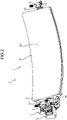
- FIG. 1 is a diagram illustrating a vehicle in which a head-up display device of the embodiment is installed
- FIG. 2 is a perspective view illustrating a mirror device of the embodiment
- FIG. 3 is an exploded perspective view of the mirror device in the embodiment
- FIG. 4 is a front view illustrating an input shaft of a mirror in the embodiment
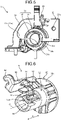
- FIG. 5 is a perspective view illustrating a holding member of the embodiment
- FIG. 6 is a perspective view illustrating a transmission member of the embodiment
- FIG. 7 is a perspective view illustrating the transmission member of the embodiment
- FIG. 8 is a perspective view illustrating a motor of the embodiment
- FIG. 1 is a diagram illustrating a vehicle in which a head-up display device of the embodiment is installed
- FIG. 2 is a perspective view illustrating a mirror device of the embodiment
- FIG. 3 is an exploded perspective view of the mirror device in the embodiment
- FIG. 4 is a front view illustrating an input shaft of a mirror in the embodiment
- FIG. 5 is a
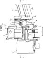
- FIG. 9 is a plan view illustrating a principal portion of the head-up display device of the embodiment
- FIG. 10 is a cross-sectional view illustrating a principal portion of the head-up display device of the embodiment.
- the X-X cross-section in FIG. 9 is illustrated.
- a head-up display device 10 As illustrated in FIG. 1 , a head-up display device 10 according to the embodiment is installed in a vehicle 100.
- the head-up display device 10 displays a virtual image 110 in front of an eye-point 201 of the vehicle 100.
- the eye-point 201 is a position that is predetermined as a viewpoint position of a driver 200 seated in a driver seat.
- the head-up display device 10 is arranged on the inside of a dashboard 101 of the vehicle 100. On the upper surface of the dashboard 101, an opening 101a is provided. The head-up display device 10 projects an image on a windshield 102 via this opening 101a.
- the windshield 102 is a reflecting portion located in front of the eye-point 201 in the vehicle 100.
- the windshield 102 has semitransparency and reflects display light DL that is incident from the head-up display device 10 toward the eye-point 201, for example.
- the driver 200 recognizes the image that is reflected by the windshield 102 as the virtual image 110. For the driver 200, the virtual image 110 is recognized as if being present in front relative to the windshield 102.
- the head-up display device 10 has a mirror device 1, an image display device 11, and a housing 12.
- the image display device 11 is a device that outputs the display light DL and is a laser scanner and a liquid-crystal display device, for example.
- the mirror device 1 reflects the display light DL that is output from the image display device 11 toward the windshield 102.
- the mirror device 1 of the present embodiment is a movable mirror device capable of changing the orientation of a reflecting surface.
- the mirror device 1 has a mirror 2, a holding member 3, a motor 4, a transmission member 5, a bearing member 6, a first spring 7, and a second spring 8.
- the mirror 2 has, as illustrated in FIG. 3 , a main unit 20, an input shaft 21, and a supported shaft 22.
- the main unit 20, the input shaft 21, and the supported shaft 22 are integrally molded by synthetic resin or the like.
- the main unit 20 has a reflecting surface 20a.
- the reflecting surface 20a is a concaved curved surface and enlarges the display light DL that is output from the image display device 11 and reflects it toward the windshield 102.
- the shape of the reflecting surface 20a of the present embodiment is a free surface.
- a reflecting layer may be formed by vapor deposition or the like.
- the mirror 2 rotates with an axis line along the longitudinal direction of the mirror 2 as a rotation center.
- the main unit 20 has a first side surface 20b and a second side surface 20c.
- the first side surface 20b and the second side surface 20c are side surfaces facing in the longitudinal direction of the main unit 20.
- the first side surface 20b and the second side surface 20c face directions opposite to each other.
- the input shaft 21 projects from the first side surface 20b.
- the input shaft 21 is a driven shaft that rotates by receiving the output torque of the motor 4.
- the shape of the exemplified input shaft 21 is a plate-like shape or a rod-like shape.
- the input shaft 21 has a substantially rectangular cross-sectional shape.
- the input shaft 21 has a first surface 21a and a second surface 21b in parallel with each other.
- the input shaft 21 has an engaging protrusion 21c protruding from the first surface 21a.
- the engaging protrusion 21c restricts the input shaft 21 from slipping out from the transmission member 5.
- the direction of the central axis line of the input shaft 21 is simply referred to as "axial direction X".
- the supported shaft 22 projects from the second side surface 20c and is located coaxially with the input shaft 21.
- the supported shaft 22 is rotatably supported by the bearing member 6.
- the shape of the exemplified supported shaft 22 is columnar.
- the first side surface 20b of the main unit 20 has a contact portion 20d that is provided on the base portion of the input shaft 21.
- the contact portion 20d is an annular raised portion surrounding the input shaft 21.
- the contact portion 20d has a contact surface 20e orthogonal to the axial direction X. The contact surface 20e comes into contact with a contact portion 35 of the holding member 3.
- the holding member 3 has a main unit 30 and a cylindrical portion 31.
- the main unit 30 and the cylindrical portion 31 are integrally molded by synthetic resin or the like.
- the main unit 30 is secured to the housing 12 by a fastening member such as a screw.
- the motor 4 is fixed to the main unit 30 and is supported by the main unit 30.
- the main unit 30 has a plate-like base portion 32 and a hook portion 33 projecting from the base portion 32.
- the base portion 32 has a substantially flat-plate shape and is orthogonal to the axial direction X.
- the base portion 32 has a through-hole 32a that runs through the base portion 32 along the plate thickness direction.
- the through-hole 32a has, as illustrated in FIG. 3 , an insertion opening 32b and a widened portion 32c.
- the insertion opening 32b is an opening into which the transmission member 5 is inserted and has a circular shape.
- the widened portion 32c is located on the outside in the radial direction with respect to the insertion opening 32b.
- the widened portion 32c is formed according to the rotation range of the mirror 2.
- a pillar portion 53 (see FIG. 6 ) of the transmission member 5 moves inside the widened portion 32c along the circumferential direction.
- the hook portion 33 is a portion to which one end of the second spring 8 is coupled.
- the exemplified hook portion 33 has a curved shape or a bent shape and is located on the outside in the radial direction with respect to the cylindrical portion 31.
- the cylindrical portion 31 has a cylindrical shape and projects along the axial direction X from the base portion 32.
- the cylindrical portion 31 has an accommodating portion 34 and the contact portion 35.
- the accommodating portion 34 is a portion on the root side of the cylindrical portion 31 and connects to the base portion 32.
- the contact portion 35 is a distal end portion of the cylindrical portion 31 and connects to the accommodating portion 34.
- the accommodating portion 34 is a portion that accommodates the first spring 7.
- the accommodating portion 34 has an inner wall 34a, an outer wall 34b, and a bottom wall 34c.
- the shape of the inner wall 34a and the outer wall 34b is cylindrical.
- the inner diameter of the outer wall 34b is greater than the outer diameter of the inner wall 34a.
- an annular accommodating space 34d that accommodates the first spring 7 is formed ( FIG. 3 ).
- the bottom wall 34c connects the distal end of the inner wall 34a and the distal end of the outer wall 34b and closes one end of the accommodating space 34d.
- the bottom wall 34c supports one end of the first spring 7 in the axial direction X. In other words, the bottom wall 34c supports the first spring 7 against the biasing force of the first spring 7.
- the contact portion 35 projects along the axial direction X from the bottom wall 34c.
- the shape of the contact portion 35 is substantially cylindrical.
- the distal end face of the contact portion 35 is orthogonal to the axial direction X.
- a cutout is provided at a position corresponding to the engaging protrusion 21c of the mirror 2. The contact portion 35 comes into contact with the contact surface 20e of the mirror 2 and positions the mirror 2 in the axial direction X.
- the transmission member 5 is a member that coaxially couples an output shaft 41 of the motor 4 and the input shaft 21 of the mirror 2.
- the transmission member 5 has a base portion 50, a fitting portion 51, a coupling portion 52, a pillar portion 53, and an arm 54.
- the base portion 50, the fitting portion 51, the coupling portion 52, the pillar portion 53, and the arm 54 are integrally molded by synthetic resin or the like.
- the base portion 50 has an annular shape and is orthogonal to the axial direction X. As illustrated in FIG. 3 , at the center of the base portion 50, an insertion opening 50a into which the output shaft of the motor 4 is inserted is provided.
- the fitting portion 51 and the coupling portion 52 are continuous along the axial direction X.
- the coupling portion 52 projects along the axial direction X from a first surface 50b of the base portion 50.
- the first surface 50b is a surface facing the mirror 2 in the axial direction X.
- the fitting portion 51 projects along the axial direction X from the distal end of the coupling portion 52.
- the coupling portion 52 is a portion coupled with the output shaft 41 of the motor 4.
- a recessed portion 52a for which the cross-sectional shape is substantially rectangular is provided in the inner part of the coupling portion 52.
- the transmission member 5 receives the output torque of the motor 4 in the recessed portion 52a.
- the fitting portion 51 is a portion to which the input shaft 21 of the mirror 2 is press-fitted. As illustrated in FIG. 6 , the fitting portion 51 is formed in a cylindrical shape for which the cross-sectional shape is substantially C-shaped. In other words, the shape of the fitting portion 51 is a shape in which a slit is formed from the distal end to the base end with respect to a cylindrical tube. On the inside of the fitting portion 51, a recessed portion 55 to which the input shaft 21 is press-fitted is formed.
- the cross-sectional shape of the recessed portion 55 at the cross-section orthogonal to the axial direction X is substantially rectangular.
- the recessed portion 55 sandwiches the first surface 21a and the second surface 21b of the input shaft 21.
- ribs 55a for reducing play that press the input shaft 21 are formed.
- One each of the rib 55a is arranged on both sides of the second surface 21b and extends in the axial direction X.
- the arm 54 latches the engaging protrusion 21c of the input shaft 21.
- the arm 54 is located at the slit portion of the fitting portion 51.
- the arm 54 projects along the axial direction X from the distal end of the coupling portion 52.
- an engaging hole 54a corresponding to the engaging protrusion 21c is provided on the distal of the arm 54.
- the pillar portion 53 projects along the axial direction X from the edge portion of the base portion 50.
- the pillar portion 53 is located on the outside in the radial direction with respect to the coupling portion 52 and the fitting portion 51 and faces the coupling portion 52 and the fitting portion 51 in the radial direction.
- a projecting portion 56 to which the second spring 8 is fixed is formed on the distal of the pillar portion 53.
- the projecting portion 56 projects outward in the radial direction centering the central axis line C1.
- the central axis line C1 is a central axis line of the fitting portion 51 and is also a central axis line of the input shaft 21 of the mirror 2.
- the shape of the exemplified projecting portion 56 is a curved hook shape or a bent hook shape.
- the pillar portion 53 has high rigidity so that the amount of deformation with respect to the spring force received from the second spring 8 is sufficiently reduced.
- the motor 4 has a main unit 40 and the output shaft 41.
- the motor 4 is a stepping motor, for example.
- the main unit 40 has fixing portions 40a that project outward.
- the fixing portion 40a is a portion that is fixed to the holding member 3 and has a through-hole 40b.
- the output shaft 41 projects from the main unit 40.
- the motor 4 outputs the motor torque generated in the main unit 40 from the output shaft 41.
- a transmission portion 41a for which the cross-sectional shape is substantially rectangular is provided at the distal end portion of the output shaft 41.
- the transmission portion 41a is inserted into the recessed portion 52a of the transmission member 5.
- the shape of the transmission portion 41a is in a shape capable of transmitting the torque to the transmission member 5 and in a shape having a slight gap with the recessed portion 52a so as to be relatively movable in the axial direction X with respect to the recessed portion 52a.
- the transmission portion 41a of the present embodiment is configured so as to be slidable in the axial direction with respect to the recessed portion 52a.
- the output torque of the motor 4 is transmitted from the transmission portion 41a to the input shaft 21 of the mirror 2 via the transmission member 5.
- the bearing member 6 rotatably supports the supported shaft 22 of the mirror 2.
- the exemplified bearing member 6 is a slide bearing that supports the supported shaft 22 to be slidable.
- the bearing member 6 is secured to the housing 12.
- the first spring 7 is an elastic spring and is a coil spring, for example. With reference to FIG. 3 , an overall structure of the mirror device 1 will be described.
- the first spring 7 is accommodated in the accommodating space 34d of the holding member 3.
- the fitting portion 51 of the transmission member 5 is inserted into the cylindrical portion 31 of the holding member 3.
- the transmission member 5 is relatively rotatable with respect to the holding member 3.
- the input shaft 21 of the mirror 2 is press-fitted to the fitting portion 51 of the transmission member 5.
- the first spring 7 is sandwiched by the holding member 3 and the transmission member 5 and is compressed.
- the first spring 7 is sandwiched by the bottom wall 34c of the holding member 3 and the base portion 50 of the transmission member 5.
- the first spring 7 is held in a state where one end in the axial direction X presses on the bottom wall 34c and the other end in the axial direction X presses on the base portion 50.
- the motor 4 is fixed to the holding member 3 while the output shaft 41 is being inserted into the transmission member 5.
- the motor 4 is fixed to the holding member 3 by male screws 9, for example.
- the input shaft 21 of the mirror 2 is supported by the housing 12 via the transmission member 5, the motor 4, and the holding member 3.
- the supported shaft 22 of the mirror 2 is supported by the housing 12 via the bearing member 6.
- the second spring 8 is an elastic spring and is a coil spring, for example. Both ends of the second spring 8 have each a ring portion. As illustrated in FIG. 2 , the ring portion on one end of the second spring 8 is hooked on the hook portion 33 of the holding member 3, and the ring portion on the other end of the second spring 8 is hooked on the projecting portion 56 of the transmission member 5.
- the second spring 8 is fixed to the holding member 3 and the transmission member 5 in an extended state. Thus, the second spring 8 exerts a pulling force on the projecting portion 56 toward the hook portion 33.
- the second spring 8 reduces the play between the input shaft 21 and the output shaft 41 in the rotational direction.
- FIG. 9 and FIG. 10 a state is illustrated where assembling of the mirror 2, the holding member 3, the motor 4, the transmission member 5, the first spring 7, and the second spring 8 is completed.
- the hook portion 33 and the projecting portion 56 are located at the same position in the axial direction X. That is, the head-up display device 10 is configured so that, by the second spring 8, the force in the circumferential direction is exerted on the projecting portion 56 and the force in the axial direction X is not exerted.
- the input shaft 21 of the mirror 2 is press-fitted to the fitting portion 51 of the transmission member 5.
- the engaging protrusion 21c of the mirror 2 is engaged with the engaging hole 54a of the transmission member 5.
- the output shaft 41 of the motor 4 is coaxially located on the extended line of the input shaft 21.
- the first spring 7 is squeezed between the bottom wall 34c of the holding member 3 and the base portion 50 of the transmission member 5.
- the first spring 7 imparts the biasing force F1 along the axial direction X to the transmission member 5.
- the biasing force F1 is the force oriented to bring the mirror 2 close to the output shaft 41.
- the biasing force F1 presses the transmission member 5 toward the main unit 40 of the motor 4.
- the torque transmission area between the output shaft 41 and the coupling portion 52 is appropriately ensured.
- the head-up display device 10 of the present embodiment has the image display device 11, the mirror 2, the motor 4, the transmission member 5, the holding member 3, and the first spring 7.
- the image display device 11 is a device that outputs the display light DL of the image.
- the mirror 2 has the reflecting surface 20a and the input shaft 21 and is rotatable.
- the reflecting surface 20a reflects the display light DL toward the reflecting portion arranged in front of the driver 200.
- the motor 4 has the output shaft 41 located on the extended line of the input shaft 21 and rotates the output shaft 41.
- the transmission member 5 has the fitting portion 51 and the coupling portion 52 and is a member that transmits the output torque of the motor 4 from the output shaft 41 to the input shaft 21.
- the fitting portion 51 is cylindrical and is a portion to which the input shaft 21 is press-fitted.
- the coupling portion 52 is a portion that is coupled with the output shaft 41.
- the holding member 3 is a member that holds the motor 4.
- the first spring 7 is a spring interposed between the holding member 3 and the transmission member 5. The first spring 7 imparts, to the transmission member 5, the biasing force F1 oriented to bring the mirror 2 close to the output shaft 41 along the axial direction X of the input shaft 21.
- the configuration of transmitting the torque from the motor 4 to the input shaft 21 of the mirror 2 is downsized.
- arranging the output shaft 41 of the motor 4 and the input shaft 21 of the mirror 2 coaxially and in close proximity allows downsizing.
- the output shaft 41 and the input shaft 21 are only partitioned by a thin wall.
- gears not being present between the output shaft 41 and the input shaft 21 allows the downsizing of the torque transmission structure.
- the torque transmission structure not having gears increases the responsiveness in rotating the mirror 2.
- the first spring 7 being interposed between the transmission member 5 and the holding member 3 allows downsizing of the mirror device 1.
- a configuration is assumed in which a spring that presses the mirror 2 toward the motor 4 is arranged on the side of the bearing member 6.
- the physical size of the mirror device 1 in the axial direction X is likely to increase.
- the head-up display device 10 of the present embodiment allows the downsizing of the mirror device 1 in the axial direction X.
- the deformation of the mirror 2 due to the biasing force F1 is not likely to arise.
- the deformation such as distortion is not likely to occur on the reflecting surface 20a.
- the mirror 2 has the main unit 20 having the reflecting surface 20a.
- the input shaft 21 projects from the first side surface 20b of the main unit 20.
- the holding member 3 has the hollow cylindrical portion 31 through which the transmission member 5 is inserted.
- the distal end of the cylindrical portion 31 has the contact portion 35 facing the first side surface 20b of the main unit 20 in the axial direction X.
- the first spring 7 makes the contact portion 35 contact the side surface 20b of the main unit 20 by the biasing force F1. Making the contact portion 35 contact the side surface 20b allows positioning of the mirror 2 in the axial direction X while suppressing the deformation of the mirror 2.
- the contact portion 35 comes into contact with the contact portion 20d of the mirror 2.
- the contact portion 20d is a raised portion formed to surround the input shaft 21 and has high rigidity. Thus, the deformation of the reflecting surface 20a by the force received from the contact portion 35 is reduced.
- the head-up display device 10 of the present embodiment has the second spring 8 that reduces the play in the rotational direction between the input shaft 21 and the output shaft 41.
- the transmission member 5 has the projecting portion 56 projecting outward in the radial direction centering the central axis line C1.
- the first end portion (end portion on one side) of the second spring 8 is coupled with the holding member 3 and the second end portion (end portion on the other side) of the second spring 8 is coupled with the projecting portion 56.
- the mirror device 1 of the present embodiment may be applied to devices different from the head-up display device 10.
- the mirror device 1 may be used for a projector and the like used in applications other than the vehicle, for example.
- the shapes of the transmission member 5 and the holding member 3 are not limited to the exemplified shapes.
- the shape and arrangement of the hook portion 33 of the holding member 3 are not limited to the exemplified shape and arrangement.
- the shape and arrangement of the projecting portion 56 of the transmission member 5 are not limited to the exemplified shape and arrangement.
- the head-up display device has the transmission member that has the cylindrical fitting portion to which the input axis of the mirror is press-fitted and the coupling portion coupled with the output shaft of the motor and transmitting the output torque of the motor from the output shaft to the input shaft, the holding member that holds the motor, and the first spring that is interposed between the holding member and the transmission member and imparts, to the transmission member, the biasing force oriented to bring the mirror close to the output shaft along the axial direction of the input shaft.
- the head-up display device in the present invention it has an effect in that downsizing can be achieved.
Landscapes
- Physics & Mathematics (AREA)
- General Physics & Mathematics (AREA)
- Optics & Photonics (AREA)
- Engineering & Computer Science (AREA)
- Chemical & Material Sciences (AREA)
- Combustion & Propulsion (AREA)
- Transportation (AREA)
- Mechanical Engineering (AREA)
- Instrument Panels (AREA)
- Devices For Indicating Variable Information By Combining Individual Elements (AREA)
Abstract
Description
- The present invention relates to a head-up display device.
- Conventionally, there have been head-up display devices. In
Japanese Patent Application Laid-open No. 2014-85539 - In regard to downsizing head-up display devices, there still has been room for improvement. For example, if a torque transmission mechanism including from a motor to a mirror can be simplified, that leads to downsizing the head-up display devices. For example, if the number of components from the motor to the mirror is reduced, that leads to downsizing the head-up display devices.
- An object of the present invention is to provide a head-up display device capable of achieving downsizing.
- In order to achieve the above mentioned object, a head-up display device according to one aspect of the present invention includes an image display device configured to output display light of an image; a rotatable mirror having a reflecting surface configured to reflect the display light toward a reflecting portion arranged in front of a driver, and an input shaft; a motor having an output shaft located on an extended line of the input shaft, the motor being configured to rotate the output shaft; a transmission member having a cylindrical fitting portion to which the input shaft is press-fitted and a coupling portion coupled with the output shaft, the transmission member being configured to transmit output torque of the motor from the output shaft to the input shaft; a holding member holding the motor; and a first spring interposed between the holding member and the transmission member, the first spring being configured to impart, to the transmission member, a biasing force oriented to bring the mirror close to the output shaft along an axial direction of the input shaft.
- The above and other objects, features, advantages and technical and industrial significance of this invention will be better understood by reading the following detailed description of presently preferred embodiments of the invention, when considered in connection with the accompanying drawings.
-
-
FIG. 1 is a diagram illustrating a vehicle in which a head-up display device of an embodiment is installed; -
FIG. 2 is a perspective view illustrating a mirror device of the embodiment; -
FIG. 3 is an exploded perspective view of the mirror device in the embodiment; -
FIG. 4 is a front view illustrating an input shaft of a mirror in the embodiment; -
FIG. 5 is a perspective view illustrating a holding member of the embodiment; -
FIG. 6 is a perspective view illustrating a transmission member of the embodiment; -
FIG. 7 is a perspective view illustrating the transmission member of the embodiment; -
FIG. 8 is a perspective view illustrating a motor of the embodiment; -
FIG. 9 is a plan view illustrating a principal portion of the head-up display device of the embodiment; and -
FIG. 10 is a cross-sectional view illustrating a principal portion of the head-up display device of the embodiment. - The following describes in detail a head-up display device according to an exemplary embodiment of the present invention with reference to the accompanying drawings. The invention, however, is not intended to be limited by the embodiment. The constituent elements in the following embodiment include elements easily achieved by a person skilled in the art or elements being substantially the same as the constituent elements.
- With reference to
FIG. 1 to FIG. 10 , the exemplary embodiment will be described. The present embodiment relates to a head-up display device.FIG. 1 is a diagram illustrating a vehicle in which a head-up display device of the embodiment is installed,FIG. 2 is a perspective view illustrating a mirror device of the embodiment,FIG. 3 is an exploded perspective view of the mirror device in the embodiment,FIG. 4 is a front view illustrating an input shaft of a mirror in the embodiment,FIG. 5 is a perspective view illustrating a holding member of the embodiment,FIG. 6 is a perspective view illustrating a transmission member of the embodiment,FIG. 7 is a perspective view illustrating the transmission member of the embodiment,FIG. 8 is a perspective view illustrating a motor of the embodiment,FIG. 9 is a plan view illustrating a principal portion of the head-up display device of the embodiment, andFIG. 10 is a cross-sectional view illustrating a principal portion of the head-up display device of the embodiment. InFIG. 10 , the X-X cross-section inFIG. 9 is illustrated. - As illustrated in
FIG. 1 , a head-updisplay device 10 according to the embodiment is installed in avehicle 100. The head-updisplay device 10 displays avirtual image 110 in front of an eye-point 201 of thevehicle 100. The eye-point 201 is a position that is predetermined as a viewpoint position of adriver 200 seated in a driver seat. - The head-up
display device 10 is arranged on the inside of adashboard 101 of thevehicle 100. On the upper surface of thedashboard 101, an opening 101a is provided. The head-updisplay device 10 projects an image on awindshield 102 via this opening 101a. Thewindshield 102 is a reflecting portion located in front of the eye-point 201 in thevehicle 100. Thewindshield 102 has semitransparency and reflects display light DL that is incident from the head-updisplay device 10 toward the eye-point 201, for example. Thedriver 200 recognizes the image that is reflected by thewindshield 102 as thevirtual image 110. For thedriver 200, thevirtual image 110 is recognized as if being present in front relative to thewindshield 102. - The head-up
display device 10 has amirror device 1, animage display device 11, and ahousing 12. Theimage display device 11 is a device that outputs the display light DL and is a laser scanner and a liquid-crystal display device, for example. Themirror device 1 reflects the display light DL that is output from theimage display device 11 toward thewindshield 102. Themirror device 1 of the present embodiment is a movable mirror device capable of changing the orientation of a reflecting surface. - As illustrated in
FIG. 2 andFIG. 3 , themirror device 1 has amirror 2, aholding member 3, amotor 4, atransmission member 5, a bearing member 6, afirst spring 7, and asecond spring 8. Themirror 2 has, as illustrated inFIG. 3 , amain unit 20, aninput shaft 21, and a supportedshaft 22. Themain unit 20, theinput shaft 21, and the supportedshaft 22 are integrally molded by synthetic resin or the like. Themain unit 20 has a reflectingsurface 20a. The reflectingsurface 20a is a concaved curved surface and enlarges the display light DL that is output from theimage display device 11 and reflects it toward thewindshield 102. The shape of the reflectingsurface 20a of the present embodiment is a free surface. On the reflectingsurface 20a, a reflecting layer may be formed by vapor deposition or the like. - The
mirror 2 rotates with an axis line along the longitudinal direction of themirror 2 as a rotation center. Themain unit 20 has afirst side surface 20b and asecond side surface 20c. Thefirst side surface 20b and thesecond side surface 20c are side surfaces facing in the longitudinal direction of themain unit 20. Thefirst side surface 20b and thesecond side surface 20c face directions opposite to each other. - The
input shaft 21 projects from thefirst side surface 20b. Theinput shaft 21 is a driven shaft that rotates by receiving the output torque of themotor 4. As illustrated inFIG. 3 andFIG. 4 , the shape of the exemplifiedinput shaft 21 is a plate-like shape or a rod-like shape. Theinput shaft 21 has a substantially rectangular cross-sectional shape. Theinput shaft 21 has afirst surface 21a and asecond surface 21b in parallel with each other. Theinput shaft 21 has anengaging protrusion 21c protruding from thefirst surface 21a. The engagingprotrusion 21c restricts theinput shaft 21 from slipping out from thetransmission member 5. In the following description, the direction of the central axis line of theinput shaft 21 is simply referred to as "axial direction X". - The supported
shaft 22 projects from thesecond side surface 20c and is located coaxially with theinput shaft 21. The supportedshaft 22 is rotatably supported by the bearing member 6. The shape of the exemplified supportedshaft 22 is columnar. - The
first side surface 20b of themain unit 20 has acontact portion 20d that is provided on the base portion of theinput shaft 21. Thecontact portion 20d is an annular raised portion surrounding theinput shaft 21. Thecontact portion 20d has acontact surface 20e orthogonal to the axial direction X. Thecontact surface 20e comes into contact with acontact portion 35 of the holdingmember 3. - As illustrated in
FIG. 3 andFIG. 5 , the holdingmember 3 has amain unit 30 and acylindrical portion 31. Themain unit 30 and thecylindrical portion 31 are integrally molded by synthetic resin or the like. Themain unit 30 is secured to thehousing 12 by a fastening member such as a screw. Themotor 4 is fixed to themain unit 30 and is supported by themain unit 30. Themain unit 30 has a plate-like base portion 32 and ahook portion 33 projecting from thebase portion 32. Thebase portion 32 has a substantially flat-plate shape and is orthogonal to the axial direction X. - The
base portion 32 has a through-hole 32a that runs through thebase portion 32 along the plate thickness direction. The through-hole 32a has, as illustrated inFIG. 3 , aninsertion opening 32b and a widenedportion 32c. Theinsertion opening 32b is an opening into which thetransmission member 5 is inserted and has a circular shape. The widenedportion 32c is located on the outside in the radial direction with respect to theinsertion opening 32b. The widenedportion 32c is formed according to the rotation range of themirror 2. A pillar portion 53 (seeFIG. 6 ) of thetransmission member 5 moves inside the widenedportion 32c along the circumferential direction. Thehook portion 33 is a portion to which one end of thesecond spring 8 is coupled. The exemplifiedhook portion 33 has a curved shape or a bent shape and is located on the outside in the radial direction with respect to thecylindrical portion 31. - The
cylindrical portion 31 has a cylindrical shape and projects along the axial direction X from thebase portion 32. Thecylindrical portion 31 has anaccommodating portion 34 and thecontact portion 35. Theaccommodating portion 34 is a portion on the root side of thecylindrical portion 31 and connects to thebase portion 32. Thecontact portion 35 is a distal end portion of thecylindrical portion 31 and connects to theaccommodating portion 34. - The
accommodating portion 34 is a portion that accommodates thefirst spring 7. Theaccommodating portion 34 has aninner wall 34a, anouter wall 34b, and abottom wall 34c. The shape of theinner wall 34a and theouter wall 34b is cylindrical. The inner diameter of theouter wall 34b is greater than the outer diameter of theinner wall 34a. Between the inner peripheral surface of theouter wall 34b and the outer peripheral surface of theinner wall 34a, an annularaccommodating space 34d that accommodates thefirst spring 7 is formed (FIG. 3 ). Thebottom wall 34c connects the distal end of theinner wall 34a and the distal end of theouter wall 34b and closes one end of theaccommodating space 34d. Thebottom wall 34c supports one end of thefirst spring 7 in the axial direction X. In other words, thebottom wall 34c supports thefirst spring 7 against the biasing force of thefirst spring 7. - The
contact portion 35 projects along the axial direction X from thebottom wall 34c. The shape of thecontact portion 35 is substantially cylindrical. The distal end face of thecontact portion 35 is orthogonal to the axial direction X. On the distal end portion of thecontact portion 35, a cutout is provided at a position corresponding to the engagingprotrusion 21c of themirror 2. Thecontact portion 35 comes into contact with thecontact surface 20e of themirror 2 and positions themirror 2 in the axial direction X. - The
transmission member 5 is a member that coaxially couples anoutput shaft 41 of themotor 4 and theinput shaft 21 of themirror 2. As illustrated inFIG. 6 , thetransmission member 5 has abase portion 50, afitting portion 51, acoupling portion 52, apillar portion 53, and anarm 54. Thebase portion 50, thefitting portion 51, thecoupling portion 52, thepillar portion 53, and thearm 54 are integrally molded by synthetic resin or the like. Thebase portion 50 has an annular shape and is orthogonal to the axial direction X. As illustrated inFIG. 3 , at the center of thebase portion 50, aninsertion opening 50a into which the output shaft of themotor 4 is inserted is provided. - As illustrated in
FIG. 6 , thefitting portion 51 and thecoupling portion 52 are continuous along the axial direction X. In more detail, thecoupling portion 52 projects along the axial direction X from afirst surface 50b of thebase portion 50. Thefirst surface 50b is a surface facing themirror 2 in the axial direction X. Thefitting portion 51 projects along the axial direction X from the distal end of thecoupling portion 52. Thecoupling portion 52 is a portion coupled with theoutput shaft 41 of themotor 4. As illustrated inFIG. 7 , in the inner part of thecoupling portion 52, a recessedportion 52a for which the cross-sectional shape is substantially rectangular is provided. Thetransmission member 5 receives the output torque of themotor 4 in the recessedportion 52a. - The
fitting portion 51 is a portion to which theinput shaft 21 of themirror 2 is press-fitted. As illustrated inFIG. 6 , thefitting portion 51 is formed in a cylindrical shape for which the cross-sectional shape is substantially C-shaped. In other words, the shape of thefitting portion 51 is a shape in which a slit is formed from the distal end to the base end with respect to a cylindrical tube. On the inside of thefitting portion 51, a recessedportion 55 to which theinput shaft 21 is press-fitted is formed. The cross-sectional shape of the recessedportion 55 at the cross-section orthogonal to the axial direction X is substantially rectangular. The recessedportion 55 sandwiches thefirst surface 21a and thesecond surface 21b of theinput shaft 21. In the recessedportion 55,ribs 55a for reducing play that press theinput shaft 21 are formed. One each of therib 55a is arranged on both sides of thesecond surface 21b and extends in the axial direction X. - The
arm 54 latches the engagingprotrusion 21c of theinput shaft 21. Thearm 54 is located at the slit portion of thefitting portion 51. Thearm 54 projects along the axial direction X from the distal end of thecoupling portion 52. On the distal of thearm 54, an engaginghole 54a corresponding to the engagingprotrusion 21c is provided. As illustrated inFIG. 7 and others, thepillar portion 53 projects along the axial direction X from the edge portion of thebase portion 50. Thepillar portion 53 is located on the outside in the radial direction with respect to thecoupling portion 52 and thefitting portion 51 and faces thecoupling portion 52 and thefitting portion 51 in the radial direction. - On the distal of the
pillar portion 53, a projectingportion 56 to which thesecond spring 8 is fixed is formed. As illustrated inFIG. 6 , the projectingportion 56 projects outward in the radial direction centering the central axis line C1. The central axis line C1 is a central axis line of thefitting portion 51 and is also a central axis line of theinput shaft 21 of themirror 2. The shape of the exemplified projectingportion 56 is a curved hook shape or a bent hook shape. Thepillar portion 53 has high rigidity so that the amount of deformation with respect to the spring force received from thesecond spring 8 is sufficiently reduced. - As illustrated in
FIG. 8 , themotor 4 has amain unit 40 and theoutput shaft 41. Themotor 4 is a stepping motor, for example. Themain unit 40 has fixingportions 40a that project outward. The fixingportion 40a is a portion that is fixed to the holdingmember 3 and has a through-hole 40b. Theoutput shaft 41 projects from themain unit 40. Themotor 4 outputs the motor torque generated in themain unit 40 from theoutput shaft 41. At the distal end portion of theoutput shaft 41, atransmission portion 41a for which the cross-sectional shape is substantially rectangular is provided. Thetransmission portion 41a is inserted into the recessedportion 52a of thetransmission member 5. The shape of thetransmission portion 41a is in a shape capable of transmitting the torque to thetransmission member 5 and in a shape having a slight gap with the recessedportion 52a so as to be relatively movable in the axial direction X with respect to the recessedportion 52a. Thetransmission portion 41a of the present embodiment is configured so as to be slidable in the axial direction with respect to the recessedportion 52a. The output torque of themotor 4 is transmitted from thetransmission portion 41a to theinput shaft 21 of themirror 2 via thetransmission member 5. - As illustrated in
FIG. 2 andFIG. 3 , the bearing member 6 rotatably supports the supportedshaft 22 of themirror 2. The exemplified bearing member 6 is a slide bearing that supports the supportedshaft 22 to be slidable. The bearing member 6 is secured to thehousing 12. - The
first spring 7 is an elastic spring and is a coil spring, for example. With reference toFIG. 3 , an overall structure of themirror device 1 will be described. Thefirst spring 7 is accommodated in theaccommodating space 34d of the holdingmember 3. Thefitting portion 51 of thetransmission member 5 is inserted into thecylindrical portion 31 of the holdingmember 3. Thetransmission member 5 is relatively rotatable with respect to the holdingmember 3. Theinput shaft 21 of themirror 2 is press-fitted to thefitting portion 51 of thetransmission member 5. As theinput shaft 21 is fitted in thefitting portion 51, thefirst spring 7 is sandwiched by the holdingmember 3 and thetransmission member 5 and is compressed. In more detail, thefirst spring 7 is sandwiched by thebottom wall 34c of the holdingmember 3 and thebase portion 50 of thetransmission member 5. In other words, thefirst spring 7 is held in a state where one end in the axial direction X presses on thebottom wall 34c and the other end in the axial direction X presses on thebase portion 50. - The
motor 4 is fixed to the holdingmember 3 while theoutput shaft 41 is being inserted into thetransmission member 5. Themotor 4 is fixed to the holdingmember 3 bymale screws 9, for example. Theinput shaft 21 of themirror 2 is supported by thehousing 12 via thetransmission member 5, themotor 4, and the holdingmember 3. The supportedshaft 22 of themirror 2 is supported by thehousing 12 via the bearing member 6. - The
second spring 8 is an elastic spring and is a coil spring, for example. Both ends of thesecond spring 8 have each a ring portion. As illustrated inFIG. 2 , the ring portion on one end of thesecond spring 8 is hooked on thehook portion 33 of the holdingmember 3, and the ring portion on the other end of thesecond spring 8 is hooked on the projectingportion 56 of thetransmission member 5. Thesecond spring 8 is fixed to the holdingmember 3 and thetransmission member 5 in an extended state. Thus, thesecond spring 8 exerts a pulling force on the projectingportion 56 toward thehook portion 33. Thesecond spring 8 reduces the play between theinput shaft 21 and theoutput shaft 41 in the rotational direction. - In
FIG. 9 andFIG. 10 , a state is illustrated where assembling of themirror 2, the holdingmember 3, themotor 4, thetransmission member 5, thefirst spring 7, and thesecond spring 8 is completed. As illustrated inFIG. 9 , thehook portion 33 and the projectingportion 56 are located at the same position in the axial direction X. That is, the head-updisplay device 10 is configured so that, by thesecond spring 8, the force in the circumferential direction is exerted on the projectingportion 56 and the force in the axial direction X is not exerted. Theinput shaft 21 of themirror 2 is press-fitted to thefitting portion 51 of thetransmission member 5. Thus, theinput shaft 21 is integrated with thetransmission member 5. The engagingprotrusion 21c of themirror 2 is engaged with the engaginghole 54a of thetransmission member 5. Theoutput shaft 41 of themotor 4 is coaxially located on the extended line of theinput shaft 21. - As illustrated in
FIG. 10 , thefirst spring 7 is squeezed between thebottom wall 34c of the holdingmember 3 and thebase portion 50 of thetransmission member 5. Thus, thefirst spring 7 imparts the biasing force F1 along the axial direction X to thetransmission member 5. The biasing force F1 is the force oriented to bring themirror 2 close to theoutput shaft 41. The biasing force F1 presses thetransmission member 5 toward themain unit 40 of themotor 4. Thus, the torque transmission area between theoutput shaft 41 and thecoupling portion 52 is appropriately ensured. - As in the foregoing, the head-up
display device 10 of the present embodiment has theimage display device 11, themirror 2, themotor 4, thetransmission member 5, the holdingmember 3, and thefirst spring 7. Theimage display device 11 is a device that outputs the display light DL of the image. Themirror 2 has the reflectingsurface 20a and theinput shaft 21 and is rotatable. The reflectingsurface 20a reflects the display light DL toward the reflecting portion arranged in front of thedriver 200. Themotor 4 has theoutput shaft 41 located on the extended line of theinput shaft 21 and rotates theoutput shaft 41. - The
transmission member 5 has thefitting portion 51 and thecoupling portion 52 and is a member that transmits the output torque of themotor 4 from theoutput shaft 41 to theinput shaft 21. Thefitting portion 51 is cylindrical and is a portion to which theinput shaft 21 is press-fitted. Thecoupling portion 52 is a portion that is coupled with theoutput shaft 41. The holdingmember 3 is a member that holds themotor 4. Thefirst spring 7 is a spring interposed between the holdingmember 3 and thetransmission member 5. Thefirst spring 7 imparts, to thetransmission member 5, the biasing force F1 oriented to bring themirror 2 close to theoutput shaft 41 along the axial direction X of theinput shaft 21. - According to the head-up
display device 10 of the present embodiment, the configuration of transmitting the torque from themotor 4 to theinput shaft 21 of themirror 2 is downsized. For example, arranging theoutput shaft 41 of themotor 4 and theinput shaft 21 of themirror 2 coaxially and in close proximity allows downsizing. In the present embodiment, as illustrated inFIG. 10 , theoutput shaft 41 and theinput shaft 21 are only partitioned by a thin wall. Thus, downsizing in the axial direction X is achieved. In addition, gears not being present between theoutput shaft 41 and theinput shaft 21 allows the downsizing of the torque transmission structure. Moreover, the torque transmission structure not having gears increases the responsiveness in rotating themirror 2. - In addition, the
first spring 7 being interposed between thetransmission member 5 and the holdingmember 3 allows downsizing of themirror device 1. As a comparative example, in place of thefirst spring 7, a configuration is assumed in which a spring that presses themirror 2 toward themotor 4 is arranged on the side of the bearing member 6. In the comparative example, the physical size of themirror device 1 in the axial direction X is likely to increase. Meanwhile, the head-updisplay device 10 of the present embodiment allows the downsizing of themirror device 1 in the axial direction X. - In the head-up
display device 10 of the present embodiment, because the biasing force F1 of thefirst spring 7 does not directly act on themirror 2, the deformation of themirror 2 due to the biasing force F1 is not likely to arise. For example, as compared with a case where thefirst spring 7 directly contacts themirror 2, the deformation such as distortion is not likely to occur on the reflectingsurface 20a. - In the head-up
display device 10 of the present embodiment, themirror 2 has themain unit 20 having the reflectingsurface 20a. Theinput shaft 21 projects from thefirst side surface 20b of themain unit 20. The holdingmember 3 has the hollowcylindrical portion 31 through which thetransmission member 5 is inserted. The distal end of thecylindrical portion 31 has thecontact portion 35 facing thefirst side surface 20b of themain unit 20 in the axial direction X. Thefirst spring 7 makes thecontact portion 35 contact theside surface 20b of themain unit 20 by the biasing force F1. Making thecontact portion 35 contact theside surface 20b allows positioning of themirror 2 in the axial direction X while suppressing the deformation of themirror 2. - Note that, in the head-up
display device 10 of the present embodiment, thecontact portion 35 comes into contact with thecontact portion 20d of themirror 2. Thecontact portion 20d is a raised portion formed to surround theinput shaft 21 and has high rigidity. Thus, the deformation of the reflectingsurface 20a by the force received from thecontact portion 35 is reduced. - The head-up
display device 10 of the present embodiment has thesecond spring 8 that reduces the play in the rotational direction between theinput shaft 21 and theoutput shaft 41. Thetransmission member 5 has the projectingportion 56 projecting outward in the radial direction centering the central axis line C1. The first end portion (end portion on one side) of thesecond spring 8 is coupled with the holdingmember 3 and the second end portion (end portion on the other side) of thesecond spring 8 is coupled with the projectingportion 56. With this configuration, the spring force of thesecond spring 8 is transmitted to theinput shaft 21 via thetransmission member 5. Thus, as compared with the configuration in which the spring force directly acts on themirror 2, the deformation of themirror 2 is not likely to arise. - The
mirror device 1 of the present embodiment may be applied to devices different from the head-updisplay device 10. Themirror device 1 may be used for a projector and the like used in applications other than the vehicle, for example. - The shapes of the
transmission member 5 and the holdingmember 3 are not limited to the exemplified shapes. For example, the shape and arrangement of thehook portion 33 of the holdingmember 3 are not limited to the exemplified shape and arrangement. For example, the shape and arrangement of the projectingportion 56 of thetransmission member 5 are not limited to the exemplified shape and arrangement. - The content disclosed in the above-described embodiment can be implemented in combination as appropriate.
- The head-up display device according to the present embodiment has the transmission member that has the cylindrical fitting portion to which the input axis of the mirror is press-fitted and the coupling portion coupled with the output shaft of the motor and transmitting the output torque of the motor from the output shaft to the input shaft, the holding member that holds the motor, and the first spring that is interposed between the holding member and the transmission member and imparts, to the transmission member, the biasing force oriented to bring the mirror close to the output shaft along the axial direction of the input shaft. According to the head-up display device in the present invention, it has an effect in that downsizing can be achieved.
- Although the invention has been described with respect to specific embodiments for a complete and clear disclosure, the appended claims are not to be thus limited but are to be construed as embodying all modifications and alternative constructions that may occur to one skilled in the art that fairly fall within the basic teaching herein set forth.
Claims (3)
- A head-up display device (10) comprising:an image display device (11) configured to output display light (DL) of an image;a rotatable mirror (2) having a reflecting surface (20a) configured to reflect the display light (DL) toward a reflecting portion arranged in front of a driver, and an input shaft (21);a motor (4) having an output shaft (41) located on an extended line of the input shaft (21), the motor (4) being configured to rotate the output shaft (41);a transmission member (5) having a cylindrical fitting portion (51) to which the input shaft (21) is press-fitted and a coupling portion (52) coupled with the output shaft (41), the transmission member (5) being configured to transmit output torque of the motor (4) from the output shaft (41) to the input shaft (21);a holding member (3) holding the motor (4); anda first spring (7) interposed between the holding member (3) and the transmission member (5), the first spring (7) being configured to impart, to the transmission member (5), a biasing force (F1) oriented to bring the mirror (2) close to the output shaft (41) along an axial direction (X) of the input shaft (21).
- The head-up display device (10) according to claim 1, whereinthe mirror (2) has a main unit (20) having the reflecting surface (20a),the input shaft (21) projects from a side surface (20b) of the main unit (20),the holding member (3) has a hollow cylindrical portion (31) through which the transmission member (5) is inserted,a distal end of the cylindrical portion (31) has a contact portion (35) facing the side surface (20b) of the main unit (20) in the axial direction (X), andthe first spring (7) makes the contact portion (35) contact the side surface (20b) of the main unit (20) by the biasing force (F1).
- The head-up display device (10) according to claim 1 or 2, further comprising:a second spring (8) configured to reduce play in a rotational direction between the input shaft (21) and the output shaft (41), whereinthe transmission member (5) has a projecting portion (56) projecting outward in a radial direction centering a central axis line (C1) of the input shaft (21), anda first end portion of the second spring (8) is coupled with the holding member (3) and a second end portion of the second spring (8) is coupled with the projecting portion (56).
Applications Claiming Priority (1)
| Application Number | Priority Date | Filing Date | Title |
|---|---|---|---|
| JP2021021377A JP7210623B2 (en) | 2021-02-15 | 2021-02-15 | head-up display device |
Publications (2)
| Publication Number | Publication Date |
|---|---|
| EP4043261A1 true EP4043261A1 (en) | 2022-08-17 |
| EP4043261B1 EP4043261B1 (en) | 2023-01-25 |
Family
ID=80119194
Family Applications (1)
| Application Number | Title | Priority Date | Filing Date |
|---|---|---|---|
| EP22154743.3A Active EP4043261B1 (en) | 2021-02-15 | 2022-02-02 | Head-up display device |
Country Status (4)
| Country | Link |
|---|---|
| US (1) | US11885963B2 (en) |
| EP (1) | EP4043261B1 (en) |
| JP (1) | JP7210623B2 (en) |
| CN (1) | CN114967136B (en) |
Cited By (1)
| Publication number | Priority date | Publication date | Assignee | Title |
|---|---|---|---|---|
| EP4628749A1 (en) * | 2024-04-02 | 2025-10-08 | Hyundai Mobis Co., Ltd. | Vibration absorption apparatus for head-up display driving module |
Families Citing this family (2)
| Publication number | Priority date | Publication date | Assignee | Title |
|---|---|---|---|---|
| US12043116B2 (en) * | 2021-08-24 | 2024-07-23 | Panasonic Automotive Systems Co., Ltd. | Display system and moving vehicle |
| JP7810679B2 (en) * | 2023-09-13 | 2026-02-03 | 矢崎総業株式会社 | Mirror device and vehicle display device |
Citations (4)
| Publication number | Priority date | Publication date | Assignee | Title |
|---|---|---|---|---|
| JP2011131651A (en) * | 2009-12-22 | 2011-07-07 | Denso Corp | Head-up display device |
| JP2014085539A (en) | 2012-10-24 | 2014-05-12 | Nippon Seiki Co Ltd | Head-up display device |
| JP2018128538A (en) * | 2017-02-07 | 2018-08-16 | 株式会社デンソー | Head-up display device |
| WO2020196160A1 (en) * | 2019-03-22 | 2020-10-01 | 日本精機株式会社 | Head-up display device |
Family Cites Families (7)
| Publication number | Priority date | Publication date | Assignee | Title |
|---|---|---|---|---|
| JP2017144847A (en) * | 2016-02-16 | 2017-08-24 | 株式会社デンソー | Head-up display device |
| JP6520819B2 (en) * | 2016-05-11 | 2019-05-29 | 株式会社デンソー | Display position adjustment unit and head-up display device |
| JP6642290B2 (en) * | 2016-06-14 | 2020-02-05 | 株式会社デンソー | Display position adjustment unit and head-up display device |
| JP6717278B2 (en) * | 2017-09-28 | 2020-07-01 | 株式会社デンソー | Virtual image display |
| US20190219823A1 (en) * | 2018-01-18 | 2019-07-18 | Visteon Global Technologies, Inc. | Head-up display system |
| JP6941816B2 (en) * | 2018-03-16 | 2021-09-29 | パナソニックIpマネジメント株式会社 | Rotating device and head-up display device |
| CN209962016U (en) * | 2019-04-12 | 2020-01-17 | 大陆汽车车身电子系统(芜湖)有限公司 | Head-up display |
-
2021
- 2021-02-15 JP JP2021021377A patent/JP7210623B2/en active Active
-
2022
- 2022-02-02 EP EP22154743.3A patent/EP4043261B1/en active Active
- 2022-02-10 US US17/668,943 patent/US11885963B2/en active Active
- 2022-02-11 CN CN202210128166.6A patent/CN114967136B/en active Active
Patent Citations (4)
| Publication number | Priority date | Publication date | Assignee | Title |
|---|---|---|---|---|
| JP2011131651A (en) * | 2009-12-22 | 2011-07-07 | Denso Corp | Head-up display device |
| JP2014085539A (en) | 2012-10-24 | 2014-05-12 | Nippon Seiki Co Ltd | Head-up display device |
| JP2018128538A (en) * | 2017-02-07 | 2018-08-16 | 株式会社デンソー | Head-up display device |
| WO2020196160A1 (en) * | 2019-03-22 | 2020-10-01 | 日本精機株式会社 | Head-up display device |
Cited By (1)
| Publication number | Priority date | Publication date | Assignee | Title |
|---|---|---|---|---|
| EP4628749A1 (en) * | 2024-04-02 | 2025-10-08 | Hyundai Mobis Co., Ltd. | Vibration absorption apparatus for head-up display driving module |
Also Published As
| Publication number | Publication date |
|---|---|
| CN114967136A (en) | 2022-08-30 |
| US11885963B2 (en) | 2024-01-30 |
| CN114967136B (en) | 2024-08-30 |
| JP7210623B2 (en) | 2023-01-23 |
| US20220260835A1 (en) | 2022-08-18 |
| JP2022123913A (en) | 2022-08-25 |
| EP4043261B1 (en) | 2023-01-25 |
Similar Documents
| Publication | Publication Date | Title |
|---|---|---|
| EP4043261A1 (en) | Head-up display device | |
| JP6044838B2 (en) | Head-up display device | |
| JP4973961B2 (en) | Power transmission device used for vehicle head-up display device | |
| JP6836718B2 (en) | Head-up display device | |
| JP7126075B2 (en) | head-up display device | |
| US20190086663A1 (en) | Drive device | |
| CN112817115A (en) | Mirror device | |
| EP2484559B1 (en) | Mirror for vehicle | |
| JP7053201B2 (en) | Drive | |
| CN103001383A (en) | Instrument unit | |
| CN112817116B (en) | Mirror device | |
| US20190086664A1 (en) | Drive device | |
| CN111273443B (en) | Driving device and head-up display device | |
| CN112433370B (en) | Driving device and head-up display device | |
| JP7327263B2 (en) | virtual image display | |
| JP7810679B2 (en) | Mirror device and vehicle display device | |
| CN221281329U (en) | Head-up display device | |
| JP7327261B2 (en) | virtual image display | |
| CN112987299A (en) | Head-up display device | |
| CN117806001A (en) | Reflector devices and vehicle display devices | |
| JP2025162000A (en) | Vehicle display device | |
| JP2021167872A (en) | Mirror unit and head-up display device |
Legal Events
| Date | Code | Title | Description |
|---|---|---|---|
| PUAI | Public reference made under article 153(3) epc to a published international application that has entered the european phase |
Free format text: ORIGINAL CODE: 0009012 |
|
| STAA | Information on the status of an ep patent application or granted ep patent |
Free format text: STATUS: REQUEST FOR EXAMINATION WAS MADE |
|
| 17P | Request for examination filed |
Effective date: 20220202 |
|
| AK | Designated contracting states |
Kind code of ref document: A1 Designated state(s): AL AT BE BG CH CY CZ DE DK EE ES FI FR GB GR HR HU IE IS IT LI LT LU LV MC MK MT NL NO PL PT RO RS SE SI SK SM TR |
|
| GRAP | Despatch of communication of intention to grant a patent |
Free format text: ORIGINAL CODE: EPIDOSNIGR1 |
|
| STAA | Information on the status of an ep patent application or granted ep patent |
Free format text: STATUS: GRANT OF PATENT IS INTENDED |
|
| RIC1 | Information provided on ipc code assigned before grant |
Ipc: F16C 27/02 20060101ALI20221014BHEP Ipc: G02B 27/01 20060101ALI20221014BHEP Ipc: B60K 35/00 20060101AFI20221014BHEP |
|
| INTG | Intention to grant announced |
Effective date: 20221110 |
|
| GRAS | Grant fee paid |
Free format text: ORIGINAL CODE: EPIDOSNIGR3 |
|
| GRAA | (expected) grant |
Free format text: ORIGINAL CODE: 0009210 |
|
| STAA | Information on the status of an ep patent application or granted ep patent |
Free format text: STATUS: THE PATENT HAS BEEN GRANTED |
|
| AK | Designated contracting states |
Kind code of ref document: B1 Designated state(s): AL AT BE BG CH CY CZ DE DK EE ES FI FR GB GR HR HU IE IS IT LI LT LU LV MC MK MT NL NO PL PT RO RS SE SI SK SM TR |
|
| REG | Reference to a national code |
Ref country code: GB Ref legal event code: FG4D |
|
| REG | Reference to a national code |
Ref country code: CH Ref legal event code: EP |
|
| REG | Reference to a national code |
Ref country code: AT Ref legal event code: REF Ref document number: 1545688 Country of ref document: AT Kind code of ref document: T Effective date: 20230215 Ref country code: IE Ref legal event code: FG4D |
|
| REG | Reference to a national code |
Ref country code: DE Ref legal event code: R096 Ref document number: 602022000003 Country of ref document: DE |
|
| REG | Reference to a national code |
Ref country code: LT Ref legal event code: MG9D |
|
| REG | Reference to a national code |
Ref country code: NL Ref legal event code: MP Effective date: 20230125 |
|
| RAP4 | Party data changed (patent owner data changed or rights of a patent transferred) |
Owner name: YAZAKI CORPORATION |
|
| REG | Reference to a national code |
Ref country code: AT Ref legal event code: MK05 Ref document number: 1545688 Country of ref document: AT Kind code of ref document: T Effective date: 20230125 |
|
| PG25 | Lapsed in a contracting state [announced via postgrant information from national office to epo] |
Ref country code: NL Free format text: LAPSE BECAUSE OF FAILURE TO SUBMIT A TRANSLATION OF THE DESCRIPTION OR TO PAY THE FEE WITHIN THE PRESCRIBED TIME-LIMIT Effective date: 20230125 |
|
| PG25 | Lapsed in a contracting state [announced via postgrant information from national office to epo] |
Ref country code: RS Free format text: LAPSE BECAUSE OF FAILURE TO SUBMIT A TRANSLATION OF THE DESCRIPTION OR TO PAY THE FEE WITHIN THE PRESCRIBED TIME-LIMIT Effective date: 20230125 Ref country code: PT Free format text: LAPSE BECAUSE OF FAILURE TO SUBMIT A TRANSLATION OF THE DESCRIPTION OR TO PAY THE FEE WITHIN THE PRESCRIBED TIME-LIMIT Effective date: 20230525 Ref country code: NO Free format text: LAPSE BECAUSE OF FAILURE TO SUBMIT A TRANSLATION OF THE DESCRIPTION OR TO PAY THE FEE WITHIN THE PRESCRIBED TIME-LIMIT Effective date: 20230425 Ref country code: LV Free format text: LAPSE BECAUSE OF FAILURE TO SUBMIT A TRANSLATION OF THE DESCRIPTION OR TO PAY THE FEE WITHIN THE PRESCRIBED TIME-LIMIT Effective date: 20230125 Ref country code: LT Free format text: LAPSE BECAUSE OF FAILURE TO SUBMIT A TRANSLATION OF THE DESCRIPTION OR TO PAY THE FEE WITHIN THE PRESCRIBED TIME-LIMIT Effective date: 20230125 Ref country code: HR Free format text: LAPSE BECAUSE OF FAILURE TO SUBMIT A TRANSLATION OF THE DESCRIPTION OR TO PAY THE FEE WITHIN THE PRESCRIBED TIME-LIMIT Effective date: 20230125 Ref country code: ES Free format text: LAPSE BECAUSE OF FAILURE TO SUBMIT A TRANSLATION OF THE DESCRIPTION OR TO PAY THE FEE WITHIN THE PRESCRIBED TIME-LIMIT Effective date: 20230125 Ref country code: AT Free format text: LAPSE BECAUSE OF FAILURE TO SUBMIT A TRANSLATION OF THE DESCRIPTION OR TO PAY THE FEE WITHIN THE PRESCRIBED TIME-LIMIT Effective date: 20230125 |
|
| PG25 | Lapsed in a contracting state [announced via postgrant information from national office to epo] |
Ref country code: SE Free format text: LAPSE BECAUSE OF FAILURE TO SUBMIT A TRANSLATION OF THE DESCRIPTION OR TO PAY THE FEE WITHIN THE PRESCRIBED TIME-LIMIT Effective date: 20230125 Ref country code: PL Free format text: LAPSE BECAUSE OF FAILURE TO SUBMIT A TRANSLATION OF THE DESCRIPTION OR TO PAY THE FEE WITHIN THE PRESCRIBED TIME-LIMIT Effective date: 20230125 Ref country code: IS Free format text: LAPSE BECAUSE OF FAILURE TO SUBMIT A TRANSLATION OF THE DESCRIPTION OR TO PAY THE FEE WITHIN THE PRESCRIBED TIME-LIMIT Effective date: 20230525 Ref country code: GR Free format text: LAPSE BECAUSE OF FAILURE TO SUBMIT A TRANSLATION OF THE DESCRIPTION OR TO PAY THE FEE WITHIN THE PRESCRIBED TIME-LIMIT Effective date: 20230426 Ref country code: FI Free format text: LAPSE BECAUSE OF FAILURE TO SUBMIT A TRANSLATION OF THE DESCRIPTION OR TO PAY THE FEE WITHIN THE PRESCRIBED TIME-LIMIT Effective date: 20230125 |
|
| REG | Reference to a national code |
Ref country code: DE Ref legal event code: R097 Ref document number: 602022000003 Country of ref document: DE |
|
| PG25 | Lapsed in a contracting state [announced via postgrant information from national office to epo] |
Ref country code: SM Free format text: LAPSE BECAUSE OF FAILURE TO SUBMIT A TRANSLATION OF THE DESCRIPTION OR TO PAY THE FEE WITHIN THE PRESCRIBED TIME-LIMIT Effective date: 20230125 Ref country code: RO Free format text: LAPSE BECAUSE OF FAILURE TO SUBMIT A TRANSLATION OF THE DESCRIPTION OR TO PAY THE FEE WITHIN THE PRESCRIBED TIME-LIMIT Effective date: 20230125 Ref country code: MC Free format text: LAPSE BECAUSE OF FAILURE TO SUBMIT A TRANSLATION OF THE DESCRIPTION OR TO PAY THE FEE WITHIN THE PRESCRIBED TIME-LIMIT Effective date: 20230125 Ref country code: EE Free format text: LAPSE BECAUSE OF FAILURE TO SUBMIT A TRANSLATION OF THE DESCRIPTION OR TO PAY THE FEE WITHIN THE PRESCRIBED TIME-LIMIT Effective date: 20230125 Ref country code: DK Free format text: LAPSE BECAUSE OF FAILURE TO SUBMIT A TRANSLATION OF THE DESCRIPTION OR TO PAY THE FEE WITHIN THE PRESCRIBED TIME-LIMIT Effective date: 20230125 Ref country code: CZ Free format text: LAPSE BECAUSE OF FAILURE TO SUBMIT A TRANSLATION OF THE DESCRIPTION OR TO PAY THE FEE WITHIN THE PRESCRIBED TIME-LIMIT Effective date: 20230125 |
|
| PG25 | Lapsed in a contracting state [announced via postgrant information from national office to epo] |
Ref country code: SK Free format text: LAPSE BECAUSE OF FAILURE TO SUBMIT A TRANSLATION OF THE DESCRIPTION OR TO PAY THE FEE WITHIN THE PRESCRIBED TIME-LIMIT Effective date: 20230125 |
|
| PLBE | No opposition filed within time limit |
Free format text: ORIGINAL CODE: 0009261 |
|
| STAA | Information on the status of an ep patent application or granted ep patent |
Free format text: STATUS: NO OPPOSITION FILED WITHIN TIME LIMIT |
|
| 26N | No opposition filed |
Effective date: 20231026 |
|
| PG25 | Lapsed in a contracting state [announced via postgrant information from national office to epo] |
Ref country code: SI Free format text: LAPSE BECAUSE OF FAILURE TO SUBMIT A TRANSLATION OF THE DESCRIPTION OR TO PAY THE FEE WITHIN THE PRESCRIBED TIME-LIMIT Effective date: 20230125 Ref country code: FR Free format text: LAPSE BECAUSE OF NON-PAYMENT OF DUE FEES Effective date: 20230325 |
|
| PG25 | Lapsed in a contracting state [announced via postgrant information from national office to epo] |
Ref country code: IT Free format text: LAPSE BECAUSE OF FAILURE TO SUBMIT A TRANSLATION OF THE DESCRIPTION OR TO PAY THE FEE WITHIN THE PRESCRIBED TIME-LIMIT Effective date: 20230125 |
|
| PG25 | Lapsed in a contracting state [announced via postgrant information from national office to epo] |
Ref country code: LU Free format text: LAPSE BECAUSE OF NON-PAYMENT OF DUE FEES Effective date: 20240202 |
|
| PG25 | Lapsed in a contracting state [announced via postgrant information from national office to epo] |
Ref country code: LU Free format text: LAPSE BECAUSE OF NON-PAYMENT OF DUE FEES Effective date: 20240202 |
|
| PG25 | Lapsed in a contracting state [announced via postgrant information from national office to epo] |
Ref country code: BG Free format text: LAPSE BECAUSE OF FAILURE TO SUBMIT A TRANSLATION OF THE DESCRIPTION OR TO PAY THE FEE WITHIN THE PRESCRIBED TIME-LIMIT Effective date: 20230125 |
|
| PG25 | Lapsed in a contracting state [announced via postgrant information from national office to epo] |
Ref country code: BG Free format text: LAPSE BECAUSE OF FAILURE TO SUBMIT A TRANSLATION OF THE DESCRIPTION OR TO PAY THE FEE WITHIN THE PRESCRIBED TIME-LIMIT Effective date: 20230125 |
|
| REG | Reference to a national code |
Ref country code: BE Ref legal event code: MM Effective date: 20240229 |
|
| PG25 | Lapsed in a contracting state [announced via postgrant information from national office to epo] |
Ref country code: BE Free format text: LAPSE BECAUSE OF NON-PAYMENT OF DUE FEES Effective date: 20240229 |
|
| PG25 | Lapsed in a contracting state [announced via postgrant information from national office to epo] |
Ref country code: IE Free format text: LAPSE BECAUSE OF NON-PAYMENT OF DUE FEES Effective date: 20240202 |
|
| PG25 | Lapsed in a contracting state [announced via postgrant information from national office to epo] |
Ref country code: IE Free format text: LAPSE BECAUSE OF NON-PAYMENT OF DUE FEES Effective date: 20240202 Ref country code: BE Free format text: LAPSE BECAUSE OF NON-PAYMENT OF DUE FEES Effective date: 20240229 |
|
| PG25 | Lapsed in a contracting state [announced via postgrant information from national office to epo] |
Ref country code: CY Free format text: LAPSE BECAUSE OF FAILURE TO SUBMIT A TRANSLATION OF THE DESCRIPTION OR TO PAY THE FEE WITHIN THE PRESCRIBED TIME-LIMIT; INVALID AB INITIO Effective date: 20220202 |
|
| REG | Reference to a national code |
Ref country code: CH Ref legal event code: PL |
|
| PG25 | Lapsed in a contracting state [announced via postgrant information from national office to epo] |
Ref country code: CH Free format text: LAPSE BECAUSE OF NON-PAYMENT OF DUE FEES Effective date: 20250228 |
|
| PG25 | Lapsed in a contracting state [announced via postgrant information from national office to epo] |
Ref country code: TR Free format text: LAPSE BECAUSE OF FAILURE TO SUBMIT A TRANSLATION OF THE DESCRIPTION OR TO PAY THE FEE WITHIN THE PRESCRIBED TIME-LIMIT Effective date: 20230125 |
|
| PGFP | Annual fee paid to national office [announced via postgrant information from national office to epo] |
Ref country code: DE Payment date: 20251230 Year of fee payment: 5 |