EP4043195A1 - In-situ fabrication of freeform optical surfaces - Google Patents
In-situ fabrication of freeform optical surfaces Download PDFInfo
- Publication number
- EP4043195A1 EP4043195A1 EP22157114.4A EP22157114A EP4043195A1 EP 4043195 A1 EP4043195 A1 EP 4043195A1 EP 22157114 A EP22157114 A EP 22157114A EP 4043195 A1 EP4043195 A1 EP 4043195A1
- Authority
- EP
- European Patent Office
- Prior art keywords
- optical
- freeform
- ffos
- assembly
- component
- Prior art date
- Legal status (The legal status is an assumption and is not a legal conclusion. Google has not performed a legal analysis and makes no representation as to the accuracy of the status listed.)
- Granted
Links
Images




Classifications
-
- B—PERFORMING OPERATIONS; TRANSPORTING
- B29—WORKING OF PLASTICS; WORKING OF SUBSTANCES IN A PLASTIC STATE IN GENERAL
- B29D—PRODUCING PARTICULAR ARTICLES FROM PLASTICS OR FROM SUBSTANCES IN A PLASTIC STATE
- B29D11/00—Producing optical elements, e.g. lenses or prisms
- B29D11/00009—Production of simple or compound lenses
-
- B—PERFORMING OPERATIONS; TRANSPORTING
- B29—WORKING OF PLASTICS; WORKING OF SUBSTANCES IN A PLASTIC STATE IN GENERAL
- B29D—PRODUCING PARTICULAR ARTICLES FROM PLASTICS OR FROM SUBSTANCES IN A PLASTIC STATE
- B29D11/00—Producing optical elements, e.g. lenses or prisms
- B29D11/00009—Production of simple or compound lenses
- B29D11/00403—Producing compound lenses
-
- B—PERFORMING OPERATIONS; TRANSPORTING
- B29—WORKING OF PLASTICS; WORKING OF SUBSTANCES IN A PLASTIC STATE IN GENERAL
- B29D—PRODUCING PARTICULAR ARTICLES FROM PLASTICS OR FROM SUBSTANCES IN A PLASTIC STATE
- B29D11/00—Producing optical elements, e.g. lenses or prisms
- B29D11/00009—Production of simple or compound lenses
- B29D11/0048—Moulds for lenses
- B29D11/00519—Reusable moulds
-
- B—PERFORMING OPERATIONS; TRANSPORTING
- B29—WORKING OF PLASTICS; WORKING OF SUBSTANCES IN A PLASTIC STATE IN GENERAL
- B29D—PRODUCING PARTICULAR ARTICLES FROM PLASTICS OR FROM SUBSTANCES IN A PLASTIC STATE
- B29D11/00—Producing optical elements, e.g. lenses or prisms
- B29D11/00009—Production of simple or compound lenses
- B29D11/0048—Moulds for lenses
- B29D11/00548—Moulds for lenses with surfaces formed by films
-
- B—PERFORMING OPERATIONS; TRANSPORTING
- B29—WORKING OF PLASTICS; WORKING OF SUBSTANCES IN A PLASTIC STATE IN GENERAL
- B29D—PRODUCING PARTICULAR ARTICLES FROM PLASTICS OR FROM SUBSTANCES IN A PLASTIC STATE
- B29D11/00—Producing optical elements, e.g. lenses or prisms
- B29D11/00009—Production of simple or compound lenses
- B29D11/0048—Moulds for lenses
- B29D11/00557—Moulds for lenses with deformable mould walls, e.g. to make lenses with different shapes
-
- B—PERFORMING OPERATIONS; TRANSPORTING
- B29—WORKING OF PLASTICS; WORKING OF SUBSTANCES IN A PLASTIC STATE IN GENERAL
- B29D—PRODUCING PARTICULAR ARTICLES FROM PLASTICS OR FROM SUBSTANCES IN A PLASTIC STATE
- B29D11/00—Producing optical elements, e.g. lenses or prisms
- B29D11/0073—Optical laminates
-
- B—PERFORMING OPERATIONS; TRANSPORTING
- B29—WORKING OF PLASTICS; WORKING OF SUBSTANCES IN A PLASTIC STATE IN GENERAL
- B29D—PRODUCING PARTICULAR ARTICLES FROM PLASTICS OR FROM SUBSTANCES IN A PLASTIC STATE
- B29D11/00—Producing optical elements, e.g. lenses or prisms
- B29D11/00951—Measuring, controlling or regulating
Definitions
- the present disclosure concerns the field of freeform optics (FFO).
- FFO freeform optics
- the disclosure relates to a method for fabricating and/or aligning an optical component, in particular a thin phase plate, within a beam path of an optical assembly and as part of said optical assembly.
- a beam path may be used for imaging an object using the optical assembly (imaging path) or it may be used for illuminating a scene (illumination path).
- the optical assembly may comprise at least one optical element that can receive light from or propagate light to said optical component along the beam path.
- this method is also applicable to optical components comprising a non-tunable freeform optical surface and at least one first optical element that can receive light from or propagate light to said freeform optical surface along a beam path.
- the disclosure further concerns such optical assemblies (featuring multiple optical elements, including at least one FFOS) and optical components (featuring multiple optical elements, including least one FFOS).
- the disclosure further concerns the use of a particular manufacturing tool for rapid prototyping of passive freeform optical surfaces.
- This tool comprises a control interface for controlling and driving an actuator based on an optimization goal and mounting means for mounting an optical assembly or an optical component (within the tool).
- the invention concerns a computer-implemented-method for rapidly providing passive optical components or passive optical elements with custom-designed (and manufactured) freeform optical surfaces.
- FFOS freeform optical surfaces
- FFOS provide novel possibilities for optical designs within a large variety of specifications.
- One particular asset of FFOS is that they can deliver practically "aberration-free" optical quality with a reduced number of (passive) optical components resulting in compact optical designs.
- a particular objective of the invention is to enable manufacturing of planar optical components with complex surface shapes in a rapid, precise, and resource-efficient manner, and to enable rapid prototyping of passive FFOS and thereby to accelerate product development in the field of FOS.
- the invention proposes a method as introduced at the beginning, which, in addition, is characterized by the following steps and features: the optical component features an initially tunable freeform optical surface; the optical component is arranged in the optical assembly at its final location within the assembly; using an actuator, the freeform optical surface is (actively) tuned in-situ (i.e. at its final location within the assembly) into a tuned shape according to an optimization goal; the tuned shape of the freeform optical surface (FFOS) is fixed to convert the freeform optical surface into a non-tunable frozen surface shape. By freezing the surface shape of the FFOS the component is thus transformed into a passive optical component.
- the optical component features an initially tunable freeform optical surface
- the optical component is arranged in the optical assembly at its final location within the assembly
- the freeform optical surface is (actively) tuned in-situ (i.e. at its final location within the assembly) into a tuned shape according to an optimization goal
- the tuned shape of the freeform optical surface (FFOS) is fixed to convert the
- This method is both applicable to refractive (transmissive) and reflective (partly transmissive or non-transmissive) FFOS.
- the tuning of the FFOS may comprise deforming the FFOS into a particular desired tuned shape and/or re-locating/aligning this shape to said beam path, for example by shifting the tuned shape slightly within an xy-plane that is defined by an optical z-axis characterizing said beam path.
- the fixation of the tuned FFOS may be achieved by various means.
- the FFOS which may be a reflective mirror surface for example
- the fixation according to the invention shall be permanent and irreversible thus transforming the fixated FFOS into a passive optical interface (that is optimized according to the optimization goal).
- An optical assembly may be understood herein as an optical setup (along one or more optical axes) which comprises several optical components or elements, for example an imaging lens group, an illumination system or a camera system, also including sensors and/or actuators and/or active optical components and/or optical filters etc.
- An optical component may be understood here as a separate entity that can be handled separately from other components of an assembly, for example a lens, a mirror, a prism, a beam splitter or a phase plate.
- An optical element may be understood here as a part of an optical component, for example a refractive, reflective or diffractive optical surface or a light pipe or an active optical element such as a tunable filter or tunable optical surface.
- the fabricated non-tunable FFOS may be understood as a passive optical element.
- the latter may be part of a single optical component that is a stand-alone component (as will be detailed below) or which forms an essential part of a more complex optical assembly (as laid out above).
- Optical assemblies or components designed and/or manufactured according to the invention can also comprise multiple FFOS, which have each been tuned in-situ (meaning at their respective final location within the component / the assembly) before being frozen/fixated.
- the in-situ tuning of multiple FFOS can be done simultaneously (in particular using sophisticated control algorithms as used for controlling cascaded wavefront modulators) or consecutively (i.e., one-after-the-other).
- the final assembly of a complex optical assembly often includes a step of active alignment. Such a step may be avoided because the in-situ tuning and curing also allows compensation of alignment tolerances of the other elements of the assembly.
- the in-situ tuning of at least one FFOS as proposed herein can avoid laborious final alignment of multiple optical elements or components within an assembly.
- these fine-tuned FFOS may be used as active correcting elements to compensate for alignment errors of other optical elements of the assembly (or the component) and/or other fabrication tolerances / errors.
- the method can even be applied on the spot at the location of a particular customer, thus taking into consideration a specific optimization goal, that is only known at the site of the customer.
- This is particularly interesting for medical applications, in which a medical imaging system can be tailored to the needs of a specific patient by tailoring the FFOS as part of that imaging system.
- the method may be applied to an application case A) in which the FFOS forms an inherent part of a single optical component (featuring multiple optical elements) or a complex optical assembly.
- the in-situ-tuning can be employed to boost the optical performance of the component / assembly.
- the FFOS thus serves to solve issues associated with alignment tolerances of alignment sensitive elements.
- the FFOS merely serves as a corrective element for boosting the optical performance of an optical assembly, which already delivers a meaningful but sub-optimal optical functionality before the FFOS is introduced into the beam path of that assembly.
- the FFOS will thus be an additional but not inherent optical element of the optical design of the assembly. This approach can help in situations in which an existing optical assembly is plagued by manufacturing or alignment tolerances.
- the in-situ tuning can also, at least partly, compensate alignment errors (e.g., x-y-shift, z-misalignment, tilts etc.), which have been introduced when arranging the FFOS within the assembly (e.g., introducing a phase plate forming the FFOS into the assembly at its final location) or when forming the FFOS as an optical element of an optical component (e.g., a complex prism featuring multiple optical surfaces).
- the method thus solves a major practical challenge associated with the use of complex FFOS, namely, how to align these FFOS accurately within an optical assembly or a complex optical component.
- In-situ-tuning thus also allows in-situ alignment. This is because the actuator employed can be driven such that the center or orientation of the FFOS (w.r.t. to its major optical axis) can be shifted as required.
- the proposed method can be further elaborated as described in the sub-claims:
- the method can be applied to great advantage, in case at least one passive optical component or passive optical element of said assembly is sharing said beam path with said optical component / said FFOS during the in-situ tuning of the freeform optical surface (FFOS) to be fabricated (which is already located at its final location).
- the beam path may be, in particular, a beam path of an optical metrology system that is employed for providing feedback for the in-situ tuning (as will be detailed below).
- the at least one passive optical component or passive optical element may be remote from said freeform optical surface and/or already fabricated and/or already aligned and/or it may not be fabricated from a liquid that forms the FFOS.
- a passive optical element can be an existing transmissive optical glass interface or an already existing optical surface of a mirror.
- the freeform optical surface may be located, during the in-situ tuning, in between at least two passive optical components or passive optical elements of said assembly (or stand-alone component) sharing said beam path.
- the actuator may be, at least in part but preferably fully, integrated into said passive optical component.
- the actuator may thus be rendered in-operable as soon as the freeform optical surface is fixed such that the optical component becomes a non-tunable optical component.
- the actuator will remain (at least in part) with the fabricated optical component / element.
- This concept thus suggests using a tuning-mechanism that is built in part or fully into the component to define a specific FFOS and switching this tuning mechanism off (in particular by solidifying a liquid - see below) and thus freezing the mechanism.
- various types of complex FFOS can be fabricated at low costs, because the same initially tunable FFOS of said component can be tuned into a myriad of different tuned shapes, which best meet the requirements of a particular optical assembly.
- the tuning mechanism employed may be an optofluidic tuning that is based on reshaping a liquid volume. This may be done by various actuation mechanism including electrowetting-on-dielectrics (EWOD) or other direct electrofluidic actuation mechanism. Such approaches may be realized, in particular without using a membrane.
- EWOD electrowetting-on-dielectrics
- the actuator may comprise a passive liquid that allows push-pull actuation of a tunable membrane.
- This membrane which may be transparent or reflective, may define the FFOS.
- the actuator may comprise at least one compensation actuation element, which is/are arranged outside of an optical aperture of the component.
- the at least one compensation actuation element may be arranged outside of an area, which defines the freeform optical surface that lies within said beam path used in the component or said assembly.
- a multitude of such compensation actuation elements, which are distributed in a peripheral area surrounding said optical area, can be employed / can be comprised in the actuator.
- an external actuator may be used for in-situ tuning of the FFOS.
- the actuator will not be part of the fabricated optical component / element.
- the in-situ-tuning may be performed by deforming a volume of a solidifiable liquid into a liquid shape using the actuator.
- the final non-tunable frozen freeform optical surface can be obtained by solidifying the liquid into a non-tunable optical volume, in particular a non-tunable optical layer, which defines the frozen surface shape of the freeform optical surface.
- the tuned shape of the FFOS may be the shape obtained after tuning but prior to solidification of the liquid.
- the frozen surface shape, which defines the final optical properties of the FFOS, is the shape / surface profile which is reached after fully curing/solidifying the liquid.
- the tuned shape obtained during tuning may deviate from the frozen surface shape; in particular, the FFOS may be tuned into the tuned shape as a pre-compensated configuration to achieve a particular intended frozen surface shape, as will be described below in more detail w.r.t. curing artifacts.
- the solidification of the liquid may be achieved by chemical or UV- or thermal curing for example.
- Suitable liquids are thus chemically or UV- or thermally curable polymers.
- the liquid may not even need to be transparent for the wavelength of light to be sent through the assembly.
- the liquid should be sufficiently transparent for the wavelengths of interest.
- the liquid may also be used to form an optical (i.e., wavelength selective) filter, as the liquid may absorb particular wavelengths to be blocked or at least diminished in intensity.
- the liquid may include colorants or absorbents.
- the in-situ tuning can thus also be used to achieve a particular desired amount of optical filtering/optical absorption, for example by changing the liquid shape during tuning and thereby the optical path length within the liquid and thereby the optical absorption delivered by the optical layer formed by the liquid. This is particular of interest for customizing/fine-tuning an illumination.
- the in-situ tuning can be most accurately performed in case it is based on feedback from a sensor that provides information about a current shape of the freeform optical surface.
- a curing artifact (which occurs during the solidification of said liquid) may be (at least partly) pre-compensated by in-situ tuning the freeform optical surface, considering at least one compensation factor.
- Such curing artifacts may be a shrinkage of the liquid, which may depend locally on the particular surface shape of the FFOS to be tuned (such that the shrinkage may be anisotropic, at least in magnitude) and/or a change of the refractive index of the liquid. Due to such curing artifacts, the tuned shape of the freeform optical surface may deviate from the frozen surface shape of the freeform optical surface which is reached after the liquid has been fully cured and/or solidified. In addition, the optical phase shift introduced by the FFOS may vary (due to the change in refractive index) even when the shrinkage and resulting shape deformation is negligibly small.
- the compensation factor can be obtained from pre-experiments, which characterize the specific shrinkage and/or expansion of the liquid because of the solidification, in particular as a function of said tuned shape and/or the specific change of refractive index (due to curing) of the liquid employed.
- the compensation factor can also consider at least one ambient factor such as a temperature or a humidity that is currently measured, because such factors will also affect the curing process.
- the curing of the liquid may induce a significant shift in the refractive index of the liquid.
- This index shift will thus also affect the optical phase change that is induced by the solidified liquid when a wavefront passes through the liquid.
- such changes can also be determined in pre-experiments and considered when tuning the tuned shape of the FFOS.
- the compensation factor may have the effect that the tuned shape that is tuned in-situ just before solidifying the liquid deviates from a shape that would best meet said optimization goal.
- the frozen surface shape of the FFOS which is reached after the liquid has been fully solidified/cured will be optimized to meet said optimization goal.
- the in-situ-tuning can be performed stepwise such that after an initial curing of said liquid, the freeform optical surface is re-tuned using the actuator, i.e. before the curing of the liquid is finally completed to fully fixate the freeform optical surface into the frozen surface shape (18) .
- the initial curing step may result in a 80% partial curing of the total volume of said liquid, and the remaining 20% may be cured in a second curing step, performed after the re-tuning.
- the actuator used may comprise a multitude of individually tunable actuation elements, which are arranged within an optical aperture of said optical component. This has the advantage that highly complex FFOS can be tuned accurately. In such a situation, at least two deflection points of the freeform optical surface may be tuned. Moreover, the freeform optical surface may thus be described by a surface profile which includes Zernike polynomials Zm,n with n ⁇ 3 (radial order of at least R 3 , with R being the radial coordinate). Said optical aperture may be defined as the area of the final FFOS of said component through with said beam path passes.
- FFOS complementary metal-oxide-semiconductor
- Such aberrations may be present in the optical assembly due to fabrication or alignment tolerances of the at least one (further) optical element or even due to optical aberrations, which are inherent to said element(s) and cannot be avoided.
- complex shapes are also highly beneficial for boosting the optical performance of the complete optical assembly.
- the freedom of design for the overall assembly is increased, because the freely tunable FFOS can provide novel optical functionality such that other elements of the assembly can be designed simpler (i.e., less complex, and hence easier and cheaper to fabricate) or with larger tolerances.
- the actuator may also feature multiple separately tunable actuation elements. These actuation elements may be arranged within said optical aperture and/or configured to tune a liquid interface directly (e.g., when using electrowetting-on-dielectrics (EWOD) or dielectrophoresis (DEP) as an actuation mechanism) or via a tunable membrane. In both cases different surface shapes of the liquid/the membrane and thereby of the freeform optical surface can be tuned in-situ.
- EWOD electrowetting-on-dielectrics
- DEP dielectrophoresis
- Suitable actuation elements may also be piezo-electric micro-actuators embedded into or deposited on the membrane. Such a design is particularly useful for reflective FFOS, where the actuators do not need to be transparent. If the piezo actuators offer transparency at the wavelength of interest, transmissive FFOS can be implemented.
- actuation elements can be used to deform a liquid interface (in particular, directly without a membrane) and/or said membrane (e.g., by electrostatic actuation of the membrane) into complex FFOS-shapes.
- This approach is both applicable to transmissive and reflective FFOS.
- the actuation elements may thus be used for tuned the liquid shape electrostatically, for example.
- the membrane itself may carry a counter electrode (e.g., a GND-electrode) or the membrane may carry said actuation elements (in this case a GND-electrode may be deposited on a substrate over which the membrane is suspended).
- the actuation elements can be highly transparent by using high transparency materials such as indium tin oxide (ITO) and/or by using a passive optical liquid that lowers reflective losses at the optical interfaces.
- ITO indium tin oxide
- the in-situ-tuning is performed based on (preferably optical) metrology data which are measured while the in-situ-tuning is performed.
- metrology data may be obtained: (i) from the tuned freeform optical surface of the optical element directly, for example by optical inspection of the freeform optical surface using a wavefront sensor; and/or (ii) from the optical assembly, for example by measuring the modulation transfer function or another suitable optical metric which characterizes the current optical performance of the assembly.
- Approach (i) can be useful for providing feedback for accurate tuning of the FFOS. This is particularly helpful in cases where a required optical correction, which is provided by the passive optical element / the FFOS to be fabricated, is known, for example based on an estimation or based on an optical simulation of the assembly or based on an optical premeasurement of the assembly (without the FFOS in place) or based on measured alignment errors of other elements of the assembly.
- Approach (ii) is particularly helpful for optical assemblies for which the necessary correction is not known or difficult to measure or estimate.
- the metrology data can also be evaluated against the optimization goal.
- the tuning can be performed until the metrology data, which are obtained live during the in-situ-tuning, are optimized w.r.t. to said optimization goal.
- Said goal may be one particular quantity to be maximized or a more complex set of conditions to be optimized (e.g., increasing the MTF of the overall assembly in two particular regions of spatial frequencies; reducing stray light; maximizing light throughput; minimizing wavefront errors; increasing imaging resolution or focusing quality; etc.); in other words, the optimization goal can be a complex function of multiple variables to be optimized.
- such figure of merits will largely depend on the optical assembly and its optical function to be optimized.
- the metrology data can be obtained in an optical measurement, e.g., a wavefront measurement or an MTF-measurement.
- an optical measurement e.g., a wavefront measurement or an MTF-measurement.
- a figure of merit characterizing the final optical assembly including the passive optical component such as a modulation transfer function (MTF); or a wavefront aberration; or an image distortion; or an image contrast; or a maximum number of discernible objects within a sample image; or a deviation of an illumination intensity distribution from a target distribution; or an optical resolution; or a minimum focal spot size; or a maximum light intensity and/or a maximum uniformity of illumination; or a numerical value characterizing a point-spread function
- optimization may thus mean maximizing a quantity (e.g., the MTF) and/or minimizing a/another quantity (e.g., the focal spot size).
- said optical assembly may be merely a single optical component featuring a first optical element and a second optical element, and said passive optical component providing the freeform optical surface may in fact be said second optical element.
- the method can be used for tuning in-situ an FFOS which forms an optical element (e.g., a reflective or transmissive optical interface) of a single optical component.
- the FFOS may be tuned in-situ at its final location (not within an assembly now but) within the component to be fabricated.
- the FFOS may share a common beam path with said first element. If the component to be fabricated offers already two such (pre-existing) passive optical elements, the FFOS may be located in between these at least two passive optical elements of said component to be fabricated, and all three optical elements may then share said beam path during the in-situ tuning but also in the final component.
- the freeform optical surface of the second optical element (is tuned such that it) compensates, at least partly, an optical aberration which is introduced by the first optical element.
- the newly formed FFOS can boost the optical performance of the overall optical component.
- the first element must not necessarily be the element on which light of a used beam path impinges first.
- the first element may be an element that receives light from the second element of the optical component.
- any beam path may be inversed, in principle.
- step of arranging the optical element within the optical component can thus be simply the formation and/or definition and/or fixation and/or positioning of the tunable FFOS at its final location within the optical component.
- a prism as an optical component with a first non-tunable optical element in the form of a first optical (e.g., refractive) surface and a second optical element in the form of an initially tunable (e.g., reflective) FFOS, that is fabricated according to the invention.
- first optical e.g., refractive
- second optical element e.g., an initially tunable (e.g., reflective) FFOS
- the invention also suggests an optical assembly or optical component as introduced in the beginning.
- This assembly / component is characterized in that the freeform optical surface is formed by a second optical element and has been aligned and/or fabricated with a method according to one of the claims directed towards a fabrication method and/or as described previously.
- the assembly / component may also be characterized in that it features (at least part of) a now in-operable actuator, by which the freeform optical surface has been tuned into a tuned shape (and thus fabricated).
- the invention also suggests the use of a particular manufacturing tool, which comprises a control interface for controlling and driving an actuator based on an optimization goal, and mounting means for mounting an optical assembly or an optical component (within the tool).
- This tool may be used in such a way that an optical assembly or an optical component is mounted using the mounting means into a final configuration; a computer is used to drive an actuator via the control interface; and the actuator thus initially tunes said freeform optical surfaces in-situ as an optical element of the optical assembly / the optical component into a tuned shape according to said optimization goal; finally, the tuned shape of the freeform optical surface is fixed;
- the actuator mentioned may be an external actuator (not forming part of the fabricated element/component) or an (at least partly) built-in actuator, as described previously.
- the computer which controls the actuator may also consider metrology data measured during the in-situ tuning and/or data from a sensor that provides feedback for tuning the actuator.
- the computer may be an external personal computer or mobile electronic device; the computer can also be implemented as part of the manufacturing tool, e.g., by a micro-controller with sufficient computing power.
- the control interface may be configured to receive (preferably digital) control signals from the computer and converts them to suitable electrical drive signals / drive voltages for driving the actuator.
- the control interface may supply high voltages to the actuator (e.g., > 200 V).
- the tool may further comprise any one or a combination of the following items: fixating means which are used for fixating a particular tuned shape of the FFOS - this may be a heat source or a UV-exposure system or a timer or sensor for monitoring a chemical curing process, for example; metrology means, which are used for gathering metrology data during the in-situ tuning of the FFOS, in particular a wavefront or image sensor configured to live-inspect the freeform optical surface and/or an optical metrology system for measuring at least one optical figure of merit (e.g., an image contrast, a MTF, etc.) of the assembly and/or of the optical component (to be fabricated) and/or a metrology system for indirectly measuring said tuned shape (e.g. mechanical stress sensors embedded in the tuned membrane or any other suitable sensor concept) and/or for providing feedback to said actuator.
- fixating means which are used for fixating a particular tuned shape of the FFOS - this may be a heat source or a UV-exposure system or a time
- the manufacturing tool may thus be used for smart in-situ manufacturing of FFOS as part of an optical assembly or optical component.
- residual assembly errors may be eliminated in complex optical assemblies.
- Such errors may comprise systematic design imperfections as well as random errors added during physical assembly of the components of the assembly (which will be different for every manufactured & assembly).
- the in-situ tuning of at least one FFOS can eliminate such errors and optimized optical components and assemblies can thus be obtained.
- design and assembly tolerances can be significantly relaxed, which is particularly important for FFOS.
- this particular method comprises the following steps: a first set of digital optical design data describing a desired optical assembly or optical component is delivered to a computer; the computer creates a first optical model based on the first set of design data; the computer integrates a second set of digital optical design data describing said optical component or element which features said freeform optical surface to form an extended optical model; using said extended optical model, the computer performs an optimization of the freeform optical surface according to an optimization goal an calculates an optimized tuned shape for/of the freeform optical surface; finally, the computer delivers a set of surface parameters, in particular as a set of Zernike coefficients, which describe said (optimized) tuned shape.
- the extended optical model thus describes the assembly or component after the FFOS has been (virtually) inserted (e.g., a sub-model describing the FFOS may be incorporated into the first optical model to form the extended optical model by the computer).
- the optimization of the FFOS may also include variation of a thickness of an optical layer forming the FFOS as well as a position (in x/y/z) of the FFOS within the assembly / the component.
- There may also be boundary conditions inherent to a particular assembly / component such as a maximum thickness of the layer forming a FFOS or an available space, in which the FFOS can be located. Such boundary conditions may be part of said first set of design data.
- the computer thus receives a first model as input and outputs an extended model which describes a position and optimized shape of the FFOS within the assembly component.
- the extended model also includes an optimized surface shape and/or position of said FFOS.
- the step of calculating an optimized tuned shape for the freeform optical surface may include several iterations with different types of FFOS; each of those different FFOS types may be tunable/formable with a particular one of a number of available different actuators.
- one type of actuator may be optimized for large tuning range w.r.t. to lower order aberrations, while another actuator may be optimized for tuning higher order aberrations.
- each of these different types of FFOS (which may be represented by a digital/optical model) may be characterized by a possible range of tunable surface profiles (which will be linked to the tuning range offered by the associated acutator).
- the computer can thus compute optimized tuned shapes (lying thus within the range of the chosen FFOS-type) for each of said different FFOS types. Moreover, the computer can then decide, based on said optimization goal, which of these different available FFOS types is best suited for meeting the optimization goal. Accordingly, the computer can thus deliver a set of surface parameters and the type of FFOS (chosen from a set of predefined and available FFOS types) for which these surface parameters have been optimized. Most preferably, the optical component / said freeform optical surface may then be fabricated and/or aligned / assembled using a method and/or tool as described before and using the set of surface parameters delivered by the computer. However, it is also possible to manufacture the desired custom-made optical component featuring the optimized freeform optical surface by conventional methods such as one-point diamond turning but again using said set of surface parameters which is finally delivered by the computer.
- This computer-implemented-method may be used, in particular, to implement a rapid prototyping service delivering various FFOS that are tailored to the need of a customer.
- the transfer of the required first set of digital optical design data may be done via an online portal for example.
- the set of surface parameters that the computer finally delivers may thus be employed for fabricating the freeform optical surface. Most preferably, this may be achieved by actively tuning the freeform optical surface in-situ into a tuned shape (according to said surface parameters which may serve as input data for controlling said actuator) and by finally fixing the freeform optical surface to render the freeform optical surface into a non-tunable frozen surface shape.
- the freeform optical surface of said optical component or said optical element may be fabricated using a method as described before and/or a manufacturing tool as presented herein.
- the methods, and tools according to the invention enable highly flexible manufacturing of FFOS.
- the manufacturing can be agile and may form part of a fully digitalized process chain used for rapid prototyping and/or optical system development. As the method is fast, it can result in reduced turn-around times and shortened product development cycles.
- the method may allow rapid deployment of custom-specific freeform optics at the site of the customer, in particular, using the presented tool.
- Figure 1 presents two examples of cross-sections of two classical optical components, namely a) a spherical plano-convex lens 5 with a surface profile z(p) with p being the radial coordinate and z(p) the height of the profile above the mean plane and b) a lens 5 with aspherical profile. Both lenses are designed and manufactured with perfect rotational symmetry.
- Figure 2 presents a top view on a surface profile 7 of a first optical component 1 fabricated with a method according to the invention, where the gray value represents the local z-height of the profile 7.
- This profile z(x,y) 7 lacks translational or rotational symmetry about axes normal to the mean plane 36 and thus represents a freeform optical surface 3 (FFOS).
- FFOS freeform optical surface 3
- height profiles along perpendicular cross-sections of the profile 7 (as indicated by the dashed lines) in Figure 2 will be different for this component 1, which forms a freeform optical phase plate 2 (FFPP).
- FFPP freeform optical phase plate 2
- Another way of looking at this optical component 1 and/or of characterizing its FFOS 3 is that the FFOS 3 introduces a phase-shift ⁇ ( ⁇ , ⁇ ) that varies both with the radial coordinate p as well as with the azimuth angle ⁇ (cf. Figure 2 ).
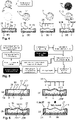
- Figure 4 illustrates the tuning and fixation/freezing of an initially tunable freeform optical surface 3 (FFOS): in step (a), an optical component 1 in the form of a transmissive phase plate 14 is seen that features a chamber 35 filled with a solidifiable liquid 11 that is covered with a membrane 21. The liquid 11 and the membrane 21 thus define the shape of the FFOS 3.
- the component 1 features a built-in actuator 10 that uses electrodes as actuation elements 15 for electrostatically deforming the membrane 21 and thereby the shape of the optical layer 8 that is formed by the liquid 11.
- the upper contour plot on the left in Figure 4 illustrates a target surface profile 27 into which the membrane 21 shall be tuned.
- the lower contour plot (which shows no lines) indicates that the membrane 21 is initially flat, as the actuator 10 has not yet tuned the membrane 21 in (a).
- suitable control signals (which are converted into suitable drive voltages)
- the actuator 10 is driven such that it deforms the membrane 21 and thereby the liquid 11 into the tuned shape 16 illustrated in (b).
- the surface profile 7 of the membrane 21 now matches closely the desired target surface profile 27.
- the tuned FFOS 3 is fixated and thereby its shape is frozen by UV-curing the liquid 11 which thus solidifies into a non-tunable solid optical layer 8.
- the final frozen shape 18 of the FFOS 3 slightly deviates from the tuned shape 16 (as can be seen by comparing the respective contour lines) and therefore also from the initial target 27, due to curing artifacts, i.e., shape deformations that occur during the solidification of the liquid 11.
- curing artifacts i.e., shape deformations that occur during the solidification of the liquid 11.
- the right upper heat map shows, there remains thus a residual error 29 between the target surface profile 27 and the final frozen shape 18 of the FFOS 3.
- the target 27 could be met perfectly by the frozen shape 18, there may be a change in the phase shift introduced by the FFOS 3, due to a change in refractive index of the liquid 11 during curing (which is another possible curing artifact).
- FIG. 5 illustrates a more detailed possible process flow for fabricating the optical component 1 of Figure 4 using the method according to the invention:
- the electrofluidic response of the liquid 11 is first characterized using metrology means 24 by tuning the liquid 11 using the built-in actuator 10.
- Electrofluidic response may be understood here as the response of the shape of the liquid in reaction to any suitable electric actuation mechanism, including direct electrofluidic actuation, such as EWOD or DEP, or indirect electrofluidic actuation such as electrostatic or piezoelectric or electromechanical (e.g., using electromechanical micro-actuators) actuation of a membrane 21 defining the liquid tuned shape 16.
- the curing of the liquid 11 has also been characterized in pre-experiments. Based on a desired target surface profile 27 and using the information from the pre-experiments and the electrofluidic characterization, a required set of control signals is calculated. The signals are converted into suitable drive voltages (using a suitable driving electronics) which are applied to the actuator 10 thus tuning the FFOS 3, as was displayed in Figure 4b .
- the information from the pre-experiments is used to calculate a set of suitable compensation parameters which allow to pre-compensate curing artifacts that will occur later during the curing of the liquid 11. Accordingly, the drive voltages slightly deviate from drive voltages that would be required for tuning the FFOS 3 into the target profile 27. The liquid 11 is thus cured while the compensated drive voltages are applied to the actuator 10. After fully curing the liquid 11, the control interface is decoupled from the component 1 which has now been transformed into a passive optical component 1 as the liquid 11 has fully solidified such that the FFOS 3 is no longer tunable. The final frozen shape 18 of the FFOS 3 deviates from the tuned shape 16 but now matches more closely the desired target 27, as the curing artifacts have been compensated by slightly adapting the drive signals delivered to the actuator 10, based on the calculated compensation parameters.
- Figure 6 shows some more details of the fabrication of an FFOS 3 by in-situ tuning according to the invention, which may be used for rapidly prototyping various FFOS 3:
- the manufacturing starts with a blank substrate 33 bearing a number of actuation elements 15 and a chamber 35 formed by confinement structures 34 (e.g. in the form of sidewalls or surface modifications for example).
- the chamber 35 is filled with a UV-curable photopolymer liquid 11 and closed by a membrane 21 which carries a (deformable) GND electrode 30 as a counter electrode.
- the surface of the membrane 21, and thereby the liquid interface forming the FFOS 3, is deformed into the desired tuned shape 16 using the integrated actuator 10, the latter being formed by the membrane 21 that can be actuated by applying suitable drive voltages to single ones of the actuation elements 15, as shown in b).
- the array of actuation electrodes 15 is driven by a close-loop control system and considering a specific optimization goal.
- the initially tuned shape 16, depicted in a solid line is intended to shrink into the target surface profile 27 depicted by the dashed line, because during the UV-curing of the liquid 11 in step (c), a shrinkage occurs (as indicated by the block arrow).
- step (c) the liquid 11 is UV-cured (thermal curing would be a suitable alternative), while the actuation electrodes 15 are kept on actuated voltage levels (as depicted already in (b)).
- step (d) the final frozen surface shape 18, which is obtained after the liquid 11 has been fully cured, thus closely resembles the intended target surface profile 27 (illustrated again as a dashed line).
- Figure 7 schematically depicts possible parts of a manufacturing tool 22 as proposed herein, which may be used for rapid prototyping of various FFOS 3 formed by a component 1 according to the invention:
- the tool 22 offers a control interface 23 for controlling and driving an actuator 10 that is built-into the component 1.
- This control is based on a particular optimization goal (namely minimizing the wavefront aberrations produced by the component 1), which forms a boundary condition for the in-situ tuning.
- the component 1 to be fabricated features two optical elements 4, namely a spherical glass lens 47 forming a first optical element 4a and the optical layer 8 formed by the liquid 11, which defines a FFOS 3 as a second optical element 4b.
- the aim of the in-situ tuning in this case is to deform the FFOS 3 in such a way that it compensates aberrations which are introduced by the first optical element 4a.
- the first optical element 4a/said glass lens 47 is thus a (pre-existing) passive optical element 56 (as it is non-tunable) which is remote from said FFOS 3 and not formed from said liquid 11, which forms the FFOS 3.
- both elements 4a, 4b share the beam path 19, which is employed by the optical metrology system 39 that forms part of the tool 22 and is used for providing control feedback (via the control interface 23 to the actuator 10) for the in-situ tuning of the FFOS 3.
- the element 4a is already fabricated and aligned within the component 1. Accordingly, during the in-situ tuning of the FFOS 3, the tuned shape 16 can be aligned in the xy-plane (standing perpendicular on the optical z-axis 55, which characterizes the beam path 19 that is shared by both elements 4a, 4b of the component 1 to be fabricated) w.r.t. to the surface shape of the lens 47/the first optical element 4a. Therefore, alignment or fabrication errors of the lens 47 can be compensated by appropriate in-situ tuning (shape transformation and/or alignment) of the FFOS 3.
- Figure 8 which will be described below.
- the control interface 23 is formed by a personal computer (with installed control software) and by control electronics which convert control signals delivered by the PC into suitable drive voltages to be delivered to the actuator 10.
- the tool 22 also comprises mounting means 26 in the form of a mechanical xyz-stage for mounting the optical component 1 and for accurately positioning the FFOS 3 within the beam path 19 of the optical metrology system 39 that forms part of the tool 22.
- This metrology system 39 (as one example of a possible metrology means 24) comprises a measurement laser 36, suitable optics (components M, BS, DBS, L, and LPF), and an image sensor 40 for optically measuring a momentary surface shape of the FFOS 3. As illustrated, this is performed by interferometric analysis of the data delivered by the image sensor 40.
- the tool 22 further comprises a UV light source 37 (as a fixation means) for UV-curing of the liquid 11 that is contained in the component 1 and forms the FFOS 3.
- the tool 22 thus forms an interferometer for live closed-loop shape optimization and monitoring of the FFOS 3 to be fabricated. Due to the sensitivity of the interferometer to environmental vibrations, the tool is arranged on a suspended optical table.
- Figure 8 shows an alternative embodiment of a tool 22 according to the invention:
- the image sensor 40 has been replaced by a Shack-Hartmann wavefront sensor (SHWS) 41, which also allows closed-loop shape optimization and monitoring of the in-situ tuned FFOS 3.
- SHWS Shack-Hartmann wavefront sensor
- a SHWS is much less sensitive to environmental vibrations.
- the tool 22 of Figure 8 is field-deployable, i.e., it may be used at the location of a customer for fabricating customized FFOS 3.
- Figure 9 illustrates the benefit of in-situ tuning of a FFOS 3 fabricated with a method as proposed herein while the optical component 1 that carries and defines the (initially tunable) FFOS 3, in this case a thin phase plate 14, is arranged in a complex optical assembly 2 at its final location 44 within the assembly 2.
- the assembly 2 forms a microscope objective featuring multiple lenses L1-L17 (and imaging from top to bottom in Figure 9 ).
- the assembly 2 of lenses L1-L17 may show residual aberrations that affect the optical imaging performance, as can be seen by comparing the generated output field 46a with the input field 45: image distortions are clearly visible which will result in sub-optimal imaging performance.
- a component 1 according to the invention is inserted into the beam path 19 of the objective at its final location 44 (cf. sub-figure (e)) and interfaced with a control interface 23.
- the still tunable FFOS 3 offered by that component 1 is tuned in-situ using the control interface 23 and a suitable actuator 10 with the optimization goal of minimizing the specific image distortions which are produced by the completed assembly 2.
- the tuned shape 16 of the FFOS 3 is optimized by measuring the output field 46a and using it as feedback for tuning said actuator 10.
- the fabricated customized FFOS 3 can also pre-compensate aberrations, which are only introduced by optical elements 4, which follow the FFOS 3 along the beam path 19, so for example the last lens L1.
- the proposed approach can not only be applied to imaging assemblies 2 but also to optical assemblies that are used for illumination.
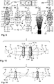
- Figures 10 and 11 show examples of how in-situ tuning of a FFOS 3 following the concept of the invention can also be applied to cases in which more than one FFOS 3 is employed within an optical assembly 2 (or within a single optical component 1):
- there is a left-hand-side optical system 48 and a right-hand-side optical system 50 and as shown in Figure 11 , there may be also an optical middle system 49.
- the performance of the overall assembly 2 / the overall optical system is boosted, respectively, by tuning the two FFOS 3 into a suitable tuned shape 16, and by freezing this shape into a final frozen surface shape 18.
- the in-situ tuning may be performed stepwise (optimizing the left FFOS 3 first, then the right FFOS 3) or simultaneously.
- multiple (initially tunable) FFOS 3 may be introduced in an optical system/within an assembly 2 in series to achieve a cumulative optical correction effect; or, as shown in Figure 11 , multiple (initially tunable) FFOS 3 may be introduced in an optical system/within an assembly 2 in different parts of the overall optical system for introducing a respective phase modulation that achieves a particular target within the respective part.
- Figure 12 illustrates the case of using two reflective FFOS 3, each fabricated in-situ at the final location 44 within an assembly 2. Shown is thus the final fabricated assembly 2, with two static and no longer tunable FFOS 3, provided each by a passive optical component 57 and having been fabricated by in-situ tuning, as proposed by the invention.
- a reflective FFOS 3 may be simply formed by adding a reflective layer on top of the tunable membrane 21 or on top of said optical layer 8 that is formed by the solidified liquid 11. Generally, the membrane 21 may also be removed from the liquid 11, once it is solidified.
- each of the fabricated FFOS 3 is located in between at least two passive optical components 57, namely components 57 of the optical systems 48 and 50.
- Figure 13 illustrates how (a) transmissive or (b) reflective FFOS 3, fabricated with a method according to the invention, may be used to deform an aberrated incoming wavefront 51 into a corrected outgoing wavefront 52, respectively.
- the aberrations present in the incoming wavefront 51 may be generated by optical elements 4 or components 1 located upstream in the beam path 19 of the overall assembly 2.
- Figure 14 illustrates the use of direct control feedback from a wavefront sensor 20 and/or of indirect control feedback from an image sensor 40. Both of these approaches may be used (alone or in combination) for improved control of the tuned shape 16 of an FFOS 3.
- Shown in Figure 14 is an optical assembly 2 that is indicated by the dotted box that forms an optical imaging system.
- the component 1 featuring the (still tunable) FFOS 3 and the image sensor 40 form part of the assembly 2 to be fabricated (which is shown in the lower half of Figure 14 ) but not the wavefront sensor 20, nor the beam splitter BS and also not the control interface 23, which will no longer be necessary and thus decoupled from the actuator 10 / the assembly 2, as soon as the FFOS 3 has been frozen into its final shape 18.
- the in-situ tuning may be based on indirect feedback from an image sensor 40 that is part of the final assembly 2 to be fabricated. For example, from data of the image sensor 40, a figure of merit such as a resolution or image brightness may be calculated. These metrology data may then be evaluated against an optimization goal. From that evaluation, a suitable feedback may be derived and delivered to the control interface 23. This feedback will be indirect, as it is not directly based on the momentary tuned shape 16.
- the image sensor 40 is illuminated by light that passes through the FFOS 3 (in other cases it may be reflected from the FFOS 3 as in the example of Figure 12 ), as shown by the imaging beam path 19 of the assembly 2.
- the FFOS 3 is tuned in-situ at its final location 44 within the assembly 2.
- the FFOS 3 is arranged between other passive optical components 57 of the assembly 2, which share the common beam path 19.
- the separate beam path 58 in Figure 14 produced by the beam splitter BS and branching of the beam path 19.
- This approach allows optical inspection of the tuned shape 16 of the FFOS 3 during in-situ tuning (in which the BS is introduced temporarily into the beam path 19) with the wavefront sensor 20.
- the sensor 20 can thus deliver a feedback to the control interface 23, which delivers drive voltages to the actuator 10 that tunes the FFOS 3.
- Wavefront sensor 20 is thus also illuminated by light passing through the FFOS 3.
- Sensor 20 can thus directly live-inspect the FFOS 3 during the in-situ tuning via the beam splitter BS (which is later removed from the assembly 2) and thus provide direct feedback to the control interface 23.
- a feedback signal may be delivered by any suitable optical metrology system 39 as depicted in Figure 13 or (alternatively or additionally) by another metrology system that indirectly measures the tuned shape 16, for example using sensors that are built into the component 1.
- Figure 15 illustrates another example of a component 1 in the form of a phase plate 14 with an (initially tunable) FFOS 3, that is formed by a membrane 21 that is actuated electrostatically, using actuation electrodes 31 deposited on a substrate 33.
- a component 1 in the form of a phase plate 14 with an (initially tunable) FFOS 3, that is formed by a membrane 21 that is actuated electrostatically, using actuation electrodes 31 deposited on a substrate 33.
- attractive electrostatic forces 53 can be used to generate a hydrodynamic push 12, as the liquid 11 is not yet cured and hence still deformable during the in-situ tuning.
- compensation actuation elements 32 visible, which are arranged outside of an relevant optical aperture 9 of the component 1.
- Said aperture 9 may be defined by a diaphragm (e.g.
- a thin opaque layer formed by the component 1 or simply by the beam path 19 that is defined by other components 1 of the assembly 2 in which the FFOS 3 is employed.
- the use of the passive liquid 11 in the component 1 thus allows push-pull actuation of the tunable membrane 21 and thereby an improved tuning range for the FFOS 3 to be defined.
- the use of the at least one compensation actuation element arranged outside of the optical aperture 9 allows to increase the tuning range even further, and thus the fabrication of more complex FFOS 3.
- FIG 16 illustrates in-situ tuning and fabrication according to the invention of a passive optical component 1, 57 that bears an FFOS 3, using a multi-use-actuator 10.
- this actuator 10 features a deformable membrane 21 on which a number of micro-piezo-actuators 59 have been arranged as actuation elements 15 for tuning the shape of the membrane 10 and thereby the shape of a FFOS 3 that is defined by a liquid 11, which will form an optical layer 8 and define the final frozen shape 18 of the FFOS 3.
- the actuation elements are arranged, in particular, within a useable optical aperture 9 of the component 1, depicted in (d).
- the fabrication of the intended passive optical component 1,57 that is shown in sub-figure (d) starts in (a) by providing a glass substrate 33 which already bears a prefabricated (and precharacterized) lens 47 as a first optical element 4a. As this lens 47 is not tunable, it forms a (first) passive optical element 56 of the component 1.
- the multi-use actuator 10 is next attached to the other side of the substrate 33, thus forming a chamber 35, which is enclosed by said tunable membrane 21.
- the chamber 35 is then filled with a solidifiable liquid 11, namely a thermally curing and transmissive photopolymer which includes a colorant that is evenly distributed in the polymer.
- the membrane 21 is tuned and deforms the liquid 11 into a liquid shape 16 that forms a FFOS 3.
- the FFOS 3 is tuned in-situ, namely at its final location 44 within the optical component 1. This tuning is performed in accordance with an optimization goal, which has been derived from an optical measurement (a mechanical surface profiling of lens 47 would also be suitable) of the first optical element 4 before starting the fabrication.
- step (c) the tuned liquid shape 16 of the FFOS 3 is frozen by thermal curing such that the liquid 11 solidifies into a permanent, solid, and non-tunable optical layer 8, which is permanently linked to the substrate 33.
- a stand-alone optical component 1 has been obtained as shown in (d).
- This component 1 is a passive optical component 57, as both of its optical elements 4a, 4b are passive optical elements 56.
- the FFOS 3 is no longer tunable but compensates optical aberrations which are introduced by said first optical element 4a, which have been measured in said optical measurement. Due to the colorant now present in the optical layer 8, the second optical element 4b not only forms a customized FFOS 3 but also a customized optical filter.
- the actuator 10 employed is not built-into the component 1, also not partly, as in previous examples.
- the actuator 10 can thus be reused multi-times for fabricating customized FFOS 3 on glass blanks 43; however, the same actuator 10 may also be used to fabricate reflective FFOS as part of a complex assembly, using a non-transmissive substrate and/or a non-transmissive liquid 11.
- the fabrication presented in Figure 16 is mold-less, because the substrate 33, which forms part of the fabricated component 1, delimits and defines the chamber 35, and not a (reusable) lower mold half (as would be the case in classical injection molding).
- the optical layer 8 that forms the FFOS 3 to be fabricated is delimited (at least partly) and/or carried by a part of the component 1 itself (this part may be a flat substrate as in the case of Figure 16 , a complex glass body of a prism, a pre-existing mirror surface, or any other suitable part of the final component to be fabricated).
- Figure 17 visualizes Zernike polynomials of different radial orders n (ordered vertically by radial degree and horizontally by azimuthal degree), which are widely used to characterize and describe a particular FFOS 3 to be defined / fabricated; according to one particular embodiment, the actuator 10 employed for the in-situ tuning can be equipped with a sufficient number of actuation elements 15 arranged within an optical aperture 9 of the FFOS 3 to be fabricated such that higher radial orders (n ⁇ 3) can be defined.
- FFOS 3 may be fabricated which include or can be described by Zernike polynomials Zn,m with n ⁇ 3 (and m ⁇ n).
- Figure 18 illustrates the advantage of the method of in-situ tuning of FFOS 3 as proposed in the example of Figure 9 , for boosting the modulation transfer function (MTF) of the complex optical assembly 2 forming the optical imaging system shown in Figure 9 (a) .
- the MTF may be considered here as an example of possible figure of merit to be optimized according to the mentioned optimization goal.
- the upper graph in Figure 18 shows the MTF as measured for the pre-existing (fabricated and aligned) optical assembly 2 of Figure 9 (a) , i.e., before introducing the component 1 featuring the FFOS 3.
- the component 1 with the FFOS 3 was next introduced into the beam path 19 of the assembly 2 and thus arranged in the optical assembly 2 at its final location 44 within the assembly 2.
- the FFOS 3 was next tuned in-situ into a tuned shape 16 as depicted in Figure 9 (c) , considering the optimization goal of maximizing the MTF; next, the tuned shape 16 was fixed by UV-curing to convert the FFOS 3 into a non-tunable frozen surface shape 18 as displayed in Figure 9 (d) . Accordingly, the component 1 was transformed at its final location 44 into a passive optical component 57.
- Figure 19 presents a flow chart summarizing single steps of a possible implementation of a method according to the invention for fabricating a passive FFOS 3 in-situ.
- active blank refers to an optical component (such as a thin phase plate) which bears an initially tunable FFOS, that is tuned in-situ as described before and later frozen into the desired passive / non-tunable FFOS 3.
- the "designated location" of the blank is thus its final location 44 within the assembly 2 forming the optical system.
- the residual aberrations of the assembly 2 including the inserted FFOS 3 may be reduced iteratively step by step, each time re-tuning the FFOS 3 until an optimized tuned shape 16 has been reached, which minimizes the residual aberrations. This may be done until a quality metric, such as a maximum allowable wavefront error in case of an imaging system or a maximum allowable variation of an illumination intensity distribution in case of an illumination system, is met.
- a quality metric such as a maximum allowable wavefront error in case of an imaging system or a maximum allowable variation of an illumination intensity distribution in case of an illumination system.
- These iterations may also (optionally) include feedback that is delivered by measuring (optically or mechanically) the momentarily tuned surface profile, i.e., the tuned shape 16 of the still tunable FFOS 3.
- the next step is to fixate the so found optimized tuned shape 16. This may include solidification / curing of a liquid 11 forming the FFOS, as explained before.
- liquid curing compensation parameters may be calculated (using a computer) based on the chosen liquid 11 and/or based on the found tuned shape 16.
- the at least one compensation factor may then be used to calculate (slightly) modified control signals, which will be translated into modified drive voltages to be applied to the actuator by a control interface 23.
- the FFOS will be (slightly) re-tuned, away from the previously optimized tuned shape 16.
- the FFOS 3 now in the re-tuned shape 16 (which slightly differs from the previously optimized tuned shape 16), will be ready for freezing by curing the liquid 11.
- the assembly 2, including the now fully frozen FFOS 3 is ready for use, as the final passive FFOS 3 is already at its final location 44 within the assembly 2.
- a slight shape transformation and/or change of the refractive index of the liquid 11 may occur, which will affect the optical performance of the optical system.
- these effects can be mitigated by the (slight) re-tuning that was done, after meeting the quality metric.
- the final frozen shape 18 can approach very closely the previously found optimized tuned shape 16 and/or the quality metric can still be met. Also note that it may be even necessary that the final frozen surface shape 18 of the FFOS 3 deviates strongly from the tuned shape 16, in case a significant change in refractive index of the liquid 11 occurs, in order to still meet the quality metric in the final assembly 2.
- FFOS complex freeform optical surfaces 3
- These surfaces 3 may form optical elements 4 as part of optical components 1 featuring at least one other passive optical element 56 or as part of more complex optical assemblies 2 featuring multiple components 1.
- tuning the FFOS 3 in-situ at its final location 44 within said component 1 or assembly 2 it is possible to boost the optical performance of the component 1 or assembly 2.
- the employment of a customizable and re-tunable FFOS 3 as a passive optical element 4b within an optical component 1 or an optical assembly 2 provides completely new approaches with respect to optical design and compensation of fabrication and alignment errors (c.f. Fig. 9 and 19 ).
Landscapes
- Engineering & Computer Science (AREA)
- Health & Medical Sciences (AREA)
- Manufacturing & Machinery (AREA)
- Ophthalmology & Optometry (AREA)
- Mechanical Engineering (AREA)
- Mechanical Light Control Or Optical Switches (AREA)
Abstract
Description
- The present disclosure concerns the field of freeform optics (FFO). In detail, the disclosure relates to a method for fabricating and/or aligning an optical component, in particular a thin phase plate, within a beam path of an optical assembly and as part of said optical assembly. Such a beam path may be used for imaging an object using the optical assembly (imaging path) or it may be used for illuminating a scene (illumination path). The optical assembly may comprise at least one optical element that can receive light from or propagate light to said optical component along the beam path. We note at this point already that this method is also applicable to optical components comprising a non-tunable freeform optical surface and at least one first optical element that can receive light from or propagate light to said freeform optical surface along a beam path.
- The disclosure further concerns such optical assemblies (featuring multiple optical elements, including at least one FFOS) and optical components (featuring multiple optical elements, including least one FFOS).
- The disclosure further concerns the use of a particular manufacturing tool for rapid prototyping of passive freeform optical surfaces. This tool comprises a control interface for controlling and driving an actuator based on an optimization goal and mounting means for mounting an optical assembly or an optical component (within the tool).
- Finally, the invention concerns a computer-implemented-method for rapidly providing passive optical components or passive optical elements with custom-designed (and manufactured) freeform optical surfaces.
- Furthermore, this application is based on the previous application
EP 21157317.5 - With advances in automation and precision metrology of optical manufacturing, the design space for optical components began to expand exponentially in the early 1990s, going far beyond the humble spherical lens. Rotationally symmetric aspheres became state of the art in the 2000's and are still one of the key tools used by optical engineers to minimize aberrations in optical systems. The next big leap came in the mid-2010's in the form of off-axis aspheres, and so-called "Freeform Optics" (FFO), which forwent rotational-symmetry entirely. This also meant that traditional grinding and polishing fabrication methods were no longer sufficient, and a plethora of new manufacturing and metrology technologies have since been proposed to manufacture freeform optical surfaces (FFOS).
- According to the norm ISO17450-1, freeform optical surfaces (FFOS) have no translational or rotational symmetry about axes normal to the mean plane. FFOS are amongst current breakthrough topics in optics because they allow for more versatile, powerful, and compact optical designs that are interesting for many industrial sectors: automotive and mechanical engineering, medicine and materials processing, aircraft construction and consumer electronics, IT and life sciences, to name a few.
- FFOS provide novel possibilities for optical designs within a large variety of specifications. One particular asset of FFOS is that they can deliver practically "aberration-free" optical quality with a reduced number of (passive) optical components resulting in compact optical designs. There are thus basically three main incentives for using FFOS: (i) achieving new optical functionality; (ii) improving optical performance; and (iii) enhancing compactness / reducing the number of optical elements in an optical assembly.
- Despite the significant advantages in design flexibility that FFOS provide, the path from design over prototyping to mass production of FFOS is currently complicated as conventional optical manufacturing methods can no longer be used, because these methods are suited primarily for machining geometries with rotational symmetry. As a result, sophisticated high-end manufacturing techniques such as single-point diamond turning, femtosecond-laser ablation, or ion exchange diffusion are used in the state-of-the-art for manufacturing FFOS. All of these approaches require enormous resources (e.g. exotic and expensive materials), and complex, bulky, and expensive equipment, can only be handled by specialists, and as manufacturing time scales with the volume to be removed, they are typically very slow, which is a severe drawback for efficient testing and product development.
- Low-cost approaches for defining FFOS such as inkjet printing on the other hand are often very limited in the optical quality of the surfaces / optical elements that can be defined. Other approaches such a using specially designed supportive frames which can define a liquid topography to be used as an optical interface have the severe drawback of allowing no tunability and hence flexibility w.r.t. the FFOS.
- In this context, it is an object of the present invention to simplify and accelerate both the optical manufacturing of FFOS and the integration of FFOS into complex optical assemblies and optical components. A particular objective of the invention is to enable manufacturing of planar optical components with complex surface shapes in a rapid, precise, and resource-efficient manner, and to enable rapid prototyping of passive FFOS and thereby to accelerate product development in the field of FOS.
- In accordance with the present invention, a method is provided according to
claim 1, which solves the afore-mentioned problem. In particular the invention proposes a method as introduced at the beginning, which, in addition, is characterized by the following steps and features: the optical component features an initially tunable freeform optical surface; the optical component is arranged in the optical assembly at its final location within the assembly; using an actuator, the freeform optical surface is (actively) tuned in-situ (i.e. at its final location within the assembly) into a tuned shape according to an optimization goal; the tuned shape of the freeform optical surface (FFOS) is fixed to convert the freeform optical surface into a non-tunable frozen surface shape. By freezing the surface shape of the FFOS the component is thus transformed into a passive optical component. - This method is both applicable to refractive (transmissive) and reflective (partly transmissive or non-transmissive) FFOS.
- The tuning of the FFOS may comprise deforming the FFOS into a particular desired tuned shape and/or re-locating/aligning this shape to said beam path, for example by shifting the tuned shape slightly within an xy-plane that is defined by an optical z-axis characterizing said beam path.
- The fixation of the tuned FFOS may be achieved by various means. For example, the FFOS (which may be a reflective mirror surface for example) in its tuned shape may be frozen by using an embedding material or a fixation means, e.g. a glue layer. Importantly, the fixation according to the invention shall be permanent and irreversible thus transforming the fixated FFOS into a passive optical interface (that is optimized according to the optimization goal).
- An optical assembly may be understood herein as an optical setup (along one or more optical axes) which comprises several optical components or elements, for example an imaging lens group, an illumination system or a camera system, also including sensors and/or actuators and/or active optical components and/or optical filters etc.
- An optical component may be understood here as a separate entity that can be handled separately from other components of an assembly, for example a lens, a mirror, a prism, a beam splitter or a phase plate.
- An optical element may be understood here as a part of an optical component, for example a refractive, reflective or diffractive optical surface or a light pipe or an active optical element such as a tunable filter or tunable optical surface.
- Accordingly, the fabricated non-tunable FFOS may be understood as a passive optical element. The latter may be part of a single optical component that is a stand-alone component (as will be detailed below) or which forms an essential part of a more complex optical assembly (as laid out above).
- Optical assemblies or components designed and/or manufactured according to the invention can also comprise multiple FFOS, which have each been tuned in-situ (meaning at their respective final location within the component / the assembly) before being frozen/fixated. The in-situ tuning of multiple FFOS can be done simultaneously (in particular using sophisticated control algorithms as used for controlling cascaded wavefront modulators) or consecutively (i.e., one-after-the-other).
- In classical manufacturing techniques, the final assembly of a complex optical assembly often includes a step of active alignment. Such a step may be avoided because the in-situ tuning and curing also allows compensation of alignment tolerances of the other elements of the assembly. In other words, the in-situ tuning of at least one FFOS as proposed herein can avoid laborious final alignment of multiple optical elements or components within an assembly. In particular when using multiple FFOS (as optical elements of a single optical component or as optical components within an assembly, in each case fabricated and/or aligned according to the method of the invention), these fine-tuned FFOS may be used as active correcting elements to compensate for alignment errors of other optical elements of the assembly (or the component) and/or other fabrication tolerances / errors.
- Another large benefit of the method presented herein is that the turn-around time in product development can be greatly reduced, because multiple configurations of an optical assembly can be rapidly tested, because the fabrication of various FFOS is so much accelerated and simplified, as compared to conventional methods.
- In addition, the method can even be applied on the spot at the location of a particular customer, thus taking into consideration a specific optimization goal, that is only known at the site of the customer. This is particularly interesting for medical applications, in which a medical imaging system can be tailored to the needs of a specific patient by tailoring the FFOS as part of that imaging system.
- The method may be applied to an application case A) in which the FFOS forms an inherent part of a single optical component (featuring multiple optical elements) or a complex optical assembly. In this case, the in-situ-tuning can be employed to boost the optical performance of the component / assembly. In case A), the FFOS thus serves to solve issues associated with alignment tolerances of alignment sensitive elements.
- In another application case B), the FFOS merely serves as a corrective element for boosting the optical performance of an optical assembly, which already delivers a meaningful but sub-optimal optical functionality before the FFOS is introduced into the beam path of that assembly. In such a case, the FFOS will thus be an additional but not inherent optical element of the optical design of the assembly. This approach can help in situations in which an existing optical assembly is plagued by manufacturing or alignment tolerances.
- The in-situ tuning can also, at least partly, compensate alignment errors (e.g., x-y-shift, z-misalignment, tilts etc.), which have been introduced when arranging the FFOS within the assembly (e.g., introducing a phase plate forming the FFOS into the assembly at its final location) or when forming the FFOS as an optical element of an optical component (e.g., a complex prism featuring multiple optical surfaces). The method thus solves a major practical challenge associated with the use of complex FFOS, namely, how to align these FFOS accurately within an optical assembly or a complex optical component. In-situ-tuning thus also allows in-situ alignment. This is because the actuator employed can be driven such that the center or orientation of the FFOS (w.r.t. to its major optical axis) can be shifted as required.
- The proposed method can be further elaborated as described in the sub-claims:
The method can be applied to great advantage, in case at least one passive optical component or passive optical element of said assembly is sharing said beam path with said optical component / said FFOS during the in-situ tuning of the freeform optical surface (FFOS) to be fabricated (which is already located at its final location). The beam path may be, in particular, a beam path of an optical metrology system that is employed for providing feedback for the in-situ tuning (as will be detailed below). The at least one passive optical component or passive optical element may be remote from said freeform optical surface and/or already fabricated and/or already aligned and/or it may not be fabricated from a liquid that forms the FFOS. For example, such a passive optical element can be an existing transmissive optical glass interface or an already existing optical surface of a mirror. - In case of a complex assembly, the freeform optical surface (to be fabricated) may be located, during the in-situ tuning, in between at least two passive optical components or passive optical elements of said assembly (or stand-alone component) sharing said beam path.
- According to one particular embodiment, the actuator may be, at least in part but preferably fully, integrated into said passive optical component. In such a case, the actuator may thus be rendered in-operable as soon as the freeform optical surface is fixed such that the optical component becomes a non-tunable optical component. In other words, the actuator will remain (at least in part) with the fabricated optical component / element. However, it is also possible to employ re-usable actuators for tuning the FFOS in-situ, which will thus not form part of the component.
- This concept thus suggests using a tuning-mechanism that is built in part or fully into the component to define a specific FFOS and switching this tuning mechanism off (in particular by solidifying a liquid - see below) and thus freezing the mechanism. As a result, various types of complex FFOS can be fabricated at low costs, because the same initially tunable FFOS of said component can be tuned into a myriad of different tuned shapes, which best meet the requirements of a particular optical assembly.
- Preferably, the tuning mechanism employed may be an optofluidic tuning that is based on reshaping a liquid volume. This may be done by various actuation mechanism including electrowetting-on-dielectrics (EWOD) or other direct electrofluidic actuation mechanism. Such approaches may be realized, in particular without using a membrane.
- Other possible tuning and/or actuation mechanism include electrostatic and piezoelectric actuation. Preferably, the actuator may comprise a passive liquid that allows push-pull actuation of a tunable membrane. This membrane, which may be transparent or reflective, may define the FFOS.
- Even more preferably, the actuator may comprise at least one compensation actuation element, which is/are arranged outside of an optical aperture of the component. Hence, the at least one compensation actuation element may be arranged outside of an area, which defines the freeform optical surface that lies within said beam path used in the component or said assembly. Most preferably, a multitude of such compensation actuation elements, which are distributed in a peripheral area surrounding said optical area, can be employed / can be comprised in the actuator.
- Alternatively, an external actuator may be used for in-situ tuning of the FFOS. In this case, the actuator will not be part of the fabricated optical component / element.
- According to one particular embodiment, the in-situ-tuning may be performed by deforming a volume of a solidifiable liquid into a liquid shape using the actuator. In this case, the final non-tunable frozen freeform optical surface can be obtained by solidifying the liquid into a non-tunable optical volume, in particular a non-tunable optical layer, which defines the frozen surface shape of the freeform optical surface.
- Accordingly, the tuned shape of the FFOS may be the shape obtained after tuning but prior to solidification of the liquid. The frozen surface shape, which defines the final optical properties of the FFOS, is the shape / surface profile which is reached after fully curing/solidifying the liquid.
- We note at this point, that the tuned shape obtained during tuning may deviate from the frozen surface shape; in particular, the FFOS may be tuned into the tuned shape as a pre-compensated configuration to achieve a particular intended frozen surface shape, as will be described below in more detail w.r.t. curing artifacts.
- The solidification of the liquid may be achieved by chemical or UV- or thermal curing for example. Suitable liquids are thus chemically or UV- or thermally curable polymers.
- If the FFOS is an external reflective surface, the liquid may not even need to be transparent for the wavelength of light to be sent through the assembly. In case the FFOS is a refractive surface or an internal reflective surface, the liquid should be sufficiently transparent for the wavelengths of interest.
- We further note that the liquid may also be used to form an optical (i.e., wavelength selective) filter, as the liquid may absorb particular wavelengths to be blocked or at least diminished in intensity. For this purpose, the liquid may include colorants or absorbents. The in-situ tuning can thus also be used to achieve a particular desired amount of optical filtering/optical absorption, for example by changing the liquid shape during tuning and thereby the optical path length within the liquid and thereby the optical absorption delivered by the optical layer formed by the liquid. This is particular of interest for customizing/fine-tuning an illumination.
- The in-situ tuning can be most accurately performed in case it is based on feedback from a sensor that provides information about a current shape of the freeform optical surface.
- According to a preferred embodiment, a curing artifact (which occurs during the solidification of said liquid) may be (at least partly) pre-compensated by in-situ tuning the freeform optical surface, considering at least one compensation factor. Such curing artifacts may be a shrinkage of the liquid, which may depend locally on the particular surface shape of the FFOS to be tuned (such that the shrinkage may be anisotropic, at least in magnitude) and/or a change of the refractive index of the liquid. Due to such curing artifacts, the tuned shape of the freeform optical surface may deviate from the frozen surface shape of the freeform optical surface which is reached after the liquid has been fully cured and/or solidified. In addition, the optical phase shift introduced by the FFOS may vary (due to the change in refractive index) even when the shrinkage and resulting shape deformation is negligibly small.
- The compensation factor can be obtained from pre-experiments, which characterize the specific shrinkage and/or expansion of the liquid because of the solidification, in particular as a function of said tuned shape and/or the specific change of refractive index (due to curing) of the liquid employed. The compensation factor can also consider at least one ambient factor such as a temperature or a humidity that is currently measured, because such factors will also affect the curing process.
- As explained, the curing of the liquid may induce a significant shift in the refractive index of the liquid. This index shift will thus also affect the optical phase change that is induced by the solidified liquid when a wavefront passes through the liquid. However, such changes can also be determined in pre-experiments and considered when tuning the tuned shape of the FFOS. Thus, said pre-compensation may also consider a shift of refractive index (RI) which occurs when solidifying the liquid (= difference between RI of uncured and fully cured liquid).
- We also note that not only empirical models may be used for calculating a suitable pre-compensation to be considered / applied when tuning the liquid in-situ, but also numerical / computational models may be used, in particular for estimating the optical effects resulting from said change in refractive index.
- The compensation factor may have the effect that the tuned shape that is tuned in-situ just before solidifying the liquid deviates from a shape that would best meet said optimization goal. However, by considering such curing artifacts, the frozen surface shape of the FFOS which is reached after the liquid has been fully solidified/cured will be optimized to meet said optimization goal.
- In particular, the in-situ-tuning can be performed stepwise such that after an initial curing of said liquid, the freeform optical surface is re-tuned using the actuator, i.e. before the curing of the liquid is finally completed to fully fixate the freeform optical surface into the frozen surface shape (18) .
- For example, the initial curing step may result in a 80% partial curing of the total volume of said liquid, and the remaining 20% may be cured in a second curing step, performed after the re-tuning.
- Moreover, by the proposed re-tuning, unwanted deformations of the FFOS during solidification of the liquid can be mitigated.
- Depending on the volume of the liquid and tuned shape of the FFOS to be achieved, it may be helpful to even re-tune the FFOS while curing is performed. Such an approach is particularly useful if the re-tuning is monitored by suitable metrology means, as laid out in more detail below.
- The actuator used may comprise a multitude of individually tunable actuation elements, which are arranged within an optical aperture of said optical component. This has the advantage that highly complex FFOS can be tuned accurately. In such a situation, at least two deflection points of the freeform optical surface may be tuned. Moreover, the freeform optical surface may thus be described by a surface profile which includes Zernike polynomials Zm,n with n ≥ 3 (radial order of at least R3, with R being the radial coordinate). Said optical aperture may be defined as the area of the final FFOS of said component through with said beam path passes.
- Using such sophisticated actuation schemes allows to define highly complex shapes of the FFOS and thus to compensate even high order optical aberrations (which may be described by Zernike polynomials Zm,n with n ≥ 3). Such aberrations may be present in the optical assembly due to fabrication or alignment tolerances of the at least one (further) optical element or even due to optical aberrations, which are inherent to said element(s) and cannot be avoided. Moreover, as already explained, such complex shapes are also highly beneficial for boosting the optical performance of the complete optical assembly. In addition, the freedom of design for the overall assembly is increased, because the freely tunable FFOS can provide novel optical functionality such that other elements of the assembly can be designed simpler (i.e., less complex, and hence easier and cheaper to fabricate) or with larger tolerances.
- The actuator may also feature multiple separately tunable actuation elements. These actuation elements may be arranged within said optical aperture and/or configured to tune a liquid interface directly (e.g., when using electrowetting-on-dielectrics (EWOD) or dielectrophoresis (DEP) as an actuation mechanism) or via a tunable membrane. In both cases different surface shapes of the liquid/the membrane and thereby of the freeform optical surface can be tuned in-situ.
- Suitable actuation elements may also be piezo-electric micro-actuators embedded into or deposited on the membrane. Such a design is particularly useful for reflective FFOS, where the actuators do not need to be transparent. If the piezo actuators offer transparency at the wavelength of interest, transmissive FFOS can be implemented.
- Another approach is to employ electrodes either on a substrate or embedded into/deposited on a tunable membrane. In both cases, such actuation elements can be used to deform a liquid interface (in particular, directly without a membrane) and/or said membrane (e.g., by electrostatic actuation of the membrane) into complex FFOS-shapes. This approach is both applicable to transmissive and reflective FFOS. The actuation elements may thus be used for tuned the liquid shape electrostatically, for example. For this purpose, the membrane itself may carry a counter electrode (e.g., a GND-electrode) or the membrane may carry said actuation elements (in this case a GND-electrode may be deposited on a substrate over which the membrane is suspended).
- The actuation elements can be highly transparent by using high transparency materials such as indium tin oxide (ITO) and/or by using a passive optical liquid that lowers reflective losses at the optical interfaces.
- Another approach suggests that the in-situ-tuning is performed based on (preferably optical) metrology data which are measured while the in-situ-tuning is performed. Such metrology data may be obtained: (i) from the tuned freeform optical surface of the optical element directly, for example by optical inspection of the freeform optical surface using a wavefront sensor; and/or (ii) from the optical assembly, for example by measuring the modulation transfer function or another suitable optical metric which characterizes the current optical performance of the assembly.
- Approach (i) can be useful for providing feedback for accurate tuning of the FFOS. This is particularly helpful in cases where a required optical correction, which is provided by the passive optical element / the FFOS to be fabricated, is known, for example based on an estimation or based on an optical simulation of the assembly or based on an optical premeasurement of the assembly (without the FFOS in place) or based on measured alignment errors of other elements of the assembly.
- Approach (ii) is particularly helpful for optical assemblies for which the necessary correction is not known or difficult to measure or estimate. By performing a live-measurement of the optical performance of the completed assembly, while actively tuning the FFOS in-situ, it is possible to tune the FFOS until the measured performance is maximized. Afterwards the so found tuned shape of the FFOS can be freezed in-situ, i.e., the FFOS can be fixed in the found optimum configuration / tuning state on the spot at the final location within the assembly. As a great advantage, no alignment must be done afterwards, as the passive optical element / the FFOS is already located in its final location within the assembly.
- The metrology data can also be evaluated against the optimization goal. In other words, the tuning can be performed until the metrology data, which are obtained live during the in-situ-tuning, are optimized w.r.t. to said optimization goal. Said goal may be one particular quantity to be maximized or a more complex set of conditions to be optimized (e.g., increasing the MTF of the overall assembly in two particular regions of spatial frequencies; reducing stray light; maximizing light throughput; minimizing wavefront errors; increasing imaging resolution or focusing quality; etc.); in other words, the optimization goal can be a complex function of multiple variables to be optimized. Of course, such figure of merits will largely depend on the optical assembly and its optical function to be optimized.
- Most preferably, the metrology data can be obtained in an optical measurement, e.g., a wavefront measurement or an MTF-measurement. However, it is also possible to obtain metrology data by other sensing approaches such as indirect sensing by measuring mechanical strain or other measurable quantities.
- To provides some examples, a figure of merit characterizing the final optical assembly including the passive optical component such as a modulation transfer function (MTF); or a wavefront aberration; or an image distortion; or an image contrast; or a maximum number of discernible objects within a sample image; or a deviation of an illumination intensity distribution from a target distribution; or an optical resolution; or a minimum focal spot size; or a maximum light intensity and/or a maximum uniformity of illumination; or a numerical value characterizing a point-spread function may be optimized as a result of the active in-situ tuning of the freeform optical surface. Optimization may thus mean maximizing a quantity (e.g., the MTF) and/or minimizing a/another quantity (e.g., the focal spot size).
- As explained in the beginning, the method presented so far is not only applicable to complex assemblies of multiple optical components but also to single optical components formed by multiple optical elements. Accordingly, said optical assembly may be merely a single optical component featuring a first optical element and a second optical element, and said passive optical component providing the freeform optical surface may in fact be said second optical element.
- In other words, the method can be used for tuning in-situ an FFOS which forms an optical element (e.g., a reflective or transmissive optical interface) of a single optical component. Again the FFOS may be tuned in-situ at its final location (not within an assembly now but) within the component to be fabricated. In particular, during the in-situ tuning of the FFOS, the FFOS may share a common beam path with said first element. If the component to be fabricated offers already two such (pre-existing) passive optical elements, the FFOS may be located in between these at least two passive optical elements of said component to be fabricated, and all three optical elements may then share said beam path during the in-situ tuning but also in the final component.
- In such cases, it is preferred if the freeform optical surface of the second optical element (is tuned such that it) compensates, at least partly, an optical aberration which is introduced by the first optical element. Thereby, the newly formed FFOS can boost the optical performance of the overall optical component.
- We note at this point that the first element must not necessarily be the element on which light of a used beam path impinges first. For example, the first element may be an element that receives light from the second element of the optical component. We also note that any beam path may be inversed, in principle.
- It is evident that all features of the method previously explained can be likewise applied to this specific case of a single component with at least two optical elements. The step of arranging the optical element within the optical component can thus be simply the formation and/or definition and/or fixation and/or positioning of the tunable FFOS at its final location within the optical component.
- For example, consider the case of a prism as an optical component with a first non-tunable optical element in the form of a first optical (e.g., refractive) surface and a second optical element in the form of an initially tunable (e.g., reflective) FFOS, that is fabricated according to the invention. Again, the in-situ tuning and freezing of the FFOS, i.e., of said second optical element, can be highly beneficial to boost the performance of the prism, in particular by compensating optical aberrations which are introduced by the first optical element (i.e., said refractive surface of the prism).
- To solve the afore-mentioned problem the invention also suggests an optical assembly or optical component as introduced in the beginning. This assembly / component is characterized in that the freeform optical surface is formed by a second optical element and has been aligned and/or fabricated with a method according to one of the claims directed towards a fabrication method and/or as described previously.
- Alternatively, or additionally, we may consider as distinctive of said assembly / component that said second optical element features actuation means, for example an initially tunable membrane and/or actuation elements. In addition, or alternatively, the assembly / component may also be characterized in that it features (at least part of) a now in-operable actuator, by which the freeform optical surface has been tuned into a tuned shape (and thus fabricated).
- For enabling rapid prototyping of passive freeform optical surfaces, the invention also suggests the use of a particular manufacturing tool, which comprises a control interface for controlling and driving an actuator based on an optimization goal, and mounting means for mounting an optical assembly or an optical component (within the tool). This tool may be used in such a way that an optical assembly or an optical component is mounted using the mounting means into a final configuration; a computer is used to drive an actuator via the control interface; and the actuator thus initially tunes said freeform optical surfaces in-situ as an optical element of the optical assembly / the optical component into a tuned shape according to said optimization goal; finally, the tuned shape of the freeform optical surface is fixed;
- The actuator mentioned may be an external actuator (not forming part of the fabricated element/component) or an (at least partly) built-in actuator, as described previously.
- It is evident from the previous explanations that the computer which controls the actuator may also consider metrology data measured during the in-situ tuning and/or data from a sensor that provides feedback for tuning the actuator. The computer may be an external personal computer or mobile electronic device; the computer can also be implemented as part of the manufacturing tool, e.g., by a micro-controller with sufficient computing power.
- The control interface may be configured to receive (preferably digital) control signals from the computer and converts them to suitable electrical drive signals / drive voltages for driving the actuator. When using electrostatic actuation, as an example, the control interface may supply high voltages to the actuator (e.g., > 200 V).
- The tool may further comprise any one or a combination of the following items: fixating means which are used for fixating a particular tuned shape of the FFOS - this may be a heat source or a UV-exposure system or a timer or sensor for monitoring a chemical curing process, for example; metrology means, which are used for gathering metrology data during the in-situ tuning of the FFOS, in particular a wavefront or image sensor configured to live-inspect the freeform optical surface and/or an optical metrology system for measuring at least one optical figure of merit (e.g., an image contrast, a MTF, etc.) of the assembly and/or of the optical component (to be fabricated) and/or a metrology system for indirectly measuring said tuned shape (e.g. mechanical stress sensors embedded in the tuned membrane or any other suitable sensor concept) and/or for providing feedback to said actuator.
- The manufacturing tool may thus be used for smart in-situ manufacturing of FFOS as part of an optical assembly or optical component. Using the proposed method and tool, residual assembly errors may be eliminated in complex optical assemblies. Such errors may comprise systematic design imperfections as well as random errors added during physical assembly of the components of the assembly (which will be different for every manufactured & assembly). The in-situ tuning of at least one FFOS can eliminate such errors and optimized optical components and assemblies can thus be obtained. Moreover, as viewed from a design perspective, design and assembly tolerances can be significantly relaxed, which is particularly important for FFOS.
- Finally, the invention also suggests a computer-implemented-method for more rapidly providing passive optical components or passive optical elements with custom-designed freeform optical surfaces. For solving the afore-mentioned problem, this particular method comprises the following steps: a first set of digital optical design data describing a desired optical assembly or optical component is delivered to a computer; the computer creates a first optical model based on the first set of design data; the computer integrates a second set of digital optical design data describing said optical component or element which features said freeform optical surface to form an extended optical model; using said extended optical model, the computer performs an optimization of the freeform optical surface according to an optimization goal an calculates an optimized tuned shape for/of the freeform optical surface; finally, the computer delivers a set of surface parameters, in particular as a set of Zernike coefficients, which describe said (optimized) tuned shape.
- We note at this point that the first set of design data does not include the FFOS, but the extended optical model does. The extended optical model thus describes the assembly or component after the FFOS has been (virtually) inserted (e.g., a sub-model describing the FFOS may be incorporated into the first optical model to form the extended optical model by the computer).
- The optimization of the FFOS may also include variation of a thickness of an optical layer forming the FFOS as well as a position (in x/y/z) of the FFOS within the assembly / the component. There may also be boundary conditions inherent to a particular assembly / component such as a maximum thickness of the layer forming a FFOS or an available space, in which the FFOS can be located. Such boundary conditions may be part of said first set of design data.
- In simple words, the computer thus receives a first model as input and outputs an extended model which describes a position and optimized shape of the FFOS within the assembly component. After optimization, the extended model also includes an optimized surface shape and/or position of said FFOS.
- The step of calculating an optimized tuned shape for the freeform optical surface may include several iterations with different types of FFOS; each of those different FFOS types may be tunable/formable with a particular one of a number of available different actuators. For example, one type of actuator may be optimized for large tuning range w.r.t. to lower order aberrations, while another actuator may be optimized for tuning higher order aberrations. Accordingly, each of these different types of FFOS (which may be represented by a digital/optical model) may be characterized by a possible range of tunable surface profiles (which will be linked to the tuning range offered by the associated acutator). Based on said optimization, the computer can thus compute optimized tuned shapes (lying thus within the range of the chosen FFOS-type) for each of said different FFOS types. Moreover, the computer can then decide, based on said optimization goal, which of these different available FFOS types is best suited for meeting the optimization goal. Accordingly, the computer can thus deliver a set of surface parameters and the type of FFOS (chosen from a set of predefined and available FFOS types) for which these surface parameters have been optimized. Most preferably, the optical component / said freeform optical surface may then be fabricated and/or aligned / assembled using a method and/or tool as described before and using the set of surface parameters delivered by the computer. However, it is also possible to manufacture the desired custom-made optical component featuring the optimized freeform optical surface by conventional methods such as one-point diamond turning but again using said set of surface parameters which is finally delivered by the computer.
- This computer-implemented-method may be used, in particular, to implement a rapid prototyping service delivering various FFOS that are tailored to the need of a customer. The transfer of the required first set of digital optical design data may be done via an online portal for example.
- The set of surface parameters that the computer finally delivers may thus be employed for fabricating the freeform optical surface. Most preferably, this may be achieved by actively tuning the freeform optical surface in-situ into a tuned shape (according to said surface parameters which may serve as input data for controlling said actuator) and by finally fixing the freeform optical surface to render the freeform optical surface into a non-tunable frozen surface shape.
- In other words, the freeform optical surface of said optical component or said optical element may be fabricated using a method as described before and/or a manufacturing tool as presented herein.
- In summary, the methods, and tools according to the invention enable highly flexible manufacturing of FFOS. The manufacturing can be agile and may form part of a fully digitalized process chain used for rapid prototyping and/or optical system development. As the method is fast, it can result in reduced turn-around times and shortened product development cycles. Moreover, the method may allow rapid deployment of custom-specific freeform optics at the site of the customer, in particular, using the presented tool.
- Preferred examples of the present invention shall now be described in more detail, although the present invention is not limited to these examples: for those skilled in the art, it is obvious that further examples of the present invention may be obtained by combining features of one or more of the patent claims with each other and/or with one or more features of an example as described or illustrated herein.
- With reference to the accompanying drawings, where features with corresponding technical function are referenced with same numerals even when these features differ in shape or design:
- Fig. 1
- presents two cross-sections of classical optical components,
- Fig. 2
- shows a top view on a freeform surface profile of a first component, fabricated with a method according to the invention,
- Fig. 3
- illustrates two cross-sections through the freeform optical surface (FFOS) of
Figure 2 , - Fig. 4
- illustrates the in-situ tuning and fixation/freezing of an initially tunable FFOS,
- Fig. 5
- illustrates a schematic process flow chart,
- Fig. 6
- illustrates details of the single steps performed during in-situ tuning and freezing of the FFOS,
- Fig. 7
- illustrates the use of live-metrology data for improved in-situ tuning,
- Fig. 8
- illustrates the use of a wavefront sensor for obtaining live-metrology data,
- Fig. 9
- illustrates the potential of the in-situ tuning proposed herein for boosting the performance of a complex imaging lens assembly,
- Fig. 10
- shows an example of in-situ tuning two FFOS which are arranged in series along a beam path,
- Fig. 11
- shows another example of in-situ tuning of multiple FFOS within an optical assembly,
- Fig. 12
- illustrates an example of using two reflective FFOS fabricated in-situ within an optical assembly,
- Fig. 13
- illustrates the examples of transmissive and reflective FFOS fabricated according to the invention,
- Fig. 14
- illustrates the use of feedback from an image sensor for improved in-situ tuning of an FFOS,
- Fig. 15
- shows a possible implementation of a built-in actuator that allows push-pull liquid actuation for in-situ tuning of an FFOS,
- Fig. 16
- illustrates in-situ tuning and fabrication of an FFOS according to the invention, using a multi-use-deformable mold,
- Fig. 17
- illustrates different Zernike polynomials,
- Fig. 18
- illustrates a simulated example of how in-situ tuning can improve the modulation-transfer-function of an optical system comprising an FFOS fabricated by the method according to the invention, and
- Fig. 19
- provides a schematic flow chart of a possible implementation of a fabrication method according to the invention.
-
Figure 1 presents two examples of cross-sections of two classical optical components, namely a) a spherical plano-convex lens 5 with a surface profile z(p) with p being the radial coordinate and z(p) the height of the profile above the mean plane and b) alens 5 with aspherical profile. Both lenses are designed and manufactured with perfect rotational symmetry. - By contrast,
Figure 2 presents a top view on asurface profile 7 of a firstoptical component 1 fabricated with a method according to the invention, where the gray value represents the local z-height of theprofile 7. This surface profile 7 (z(x,y) or z(p,8) depending on the coordinate system chosen), can be described by the formula z = 1.0*Z2,0 + 2.0*Z2,2 + 0.3*Z3,3 + 1.4*Z3,-3 + 1.0*Z5,5, with Zn,m being the Zernike polynomial Z of coefficients n,m where m and n are non-negative integers with n ≥ m ≥ 0 (m = 0 for even Zernike polynomials). This profile z(x,y) 7 lacks translational or rotational symmetry about axes normal to themean plane 36 and thus represents a freeform optical surface 3 (FFOS). In other words, height profiles along perpendicular cross-sections of the profile 7 (as indicated by the dashed lines) inFigure 2 will be different for thiscomponent 1, which forms a freeform optical phase plate 2 (FFPP). Another way of looking at thisoptical component 1 and/or of characterizing itsFFOS 3 is that theFFOS 3 introduces a phase-shift ϕ (ρ,θ) that varies both with the radial coordinate p as well as with the azimuth angle θ (cf.Figure 2 ). - Yet another way of defining a
FFOS 3, in distinction from classical optical surfaces as the ones shown inFigure 1 , is that when taking any cross-section (within in a range p = [0..Rmax] with Rmax the maximum radius), for example from the FFOS shown inFigure 2 , and rotating it around the optical z-axis by 360° thus producing a surface of revolution S, aFFOS 3 will be characterized in that it will deviate from the surface S at least at one coordinate (but typically on multiple coordinates), in particular within the optical aperture. This is readily apparent by comparing the cross-sections through thesurface profile 7 ofFigure 2 at two different azimuth angles θ illustrated inFigure 3 . It is also apparent, that there may be at least one cross-sectional height profile (at a certain angle θ), which lacks symmetry to the optical axis (running in the z-direction at x=0, y=0). -
Figure 4 illustrates the tuning and fixation/freezing of an initially tunable freeform optical surface 3 (FFOS): in step (a), anoptical component 1 in the form of a transmissive phase plate 14 is seen that features achamber 35 filled with a solidifiable liquid 11 that is covered with amembrane 21. The liquid 11 and themembrane 21 thus define the shape of theFFOS 3. Thecomponent 1 features a built-inactuator 10 that uses electrodes asactuation elements 15 for electrostatically deforming themembrane 21 and thereby the shape of theoptical layer 8 that is formed by the liquid 11. The upper contour plot on the left inFigure 4 illustrates atarget surface profile 27 into which themembrane 21 shall be tuned. The lower contour plot (which shows no lines) indicates that themembrane 21 is initially flat, as theactuator 10 has not yet tuned themembrane 21 in (a). After calculating suitable control signals (which are converted into suitable drive voltages), theactuator 10 is driven such that it deforms themembrane 21 and thereby the liquid 11 into the tunedshape 16 illustrated in (b). As the corresponding contour plot shows, thesurface profile 7 of themembrane 21 now matches closely the desiredtarget surface profile 27. In the next step (c) the tunedFFOS 3 is fixated and thereby its shape is frozen by UV-curing the liquid 11 which thus solidifies into a non-tunable solidoptical layer 8. As indicated in (d), after fully curing the liquid 11, the finalfrozen shape 18 of theFFOS 3 slightly deviates from the tuned shape 16 (as can be seen by comparing the respective contour lines) and therefore also from theinitial target 27, due to curing artifacts, i.e., shape deformations that occur during the solidification of the liquid 11. As the right upper heat map shows, there remains thus aresidual error 29 between thetarget surface profile 27 and the finalfrozen shape 18 of theFFOS 3. But even if thetarget 27 could be met perfectly by thefrozen shape 18, there may be a change in the phase shift introduced by theFFOS 3, due to a change in refractive index of the liquid 11 during curing (which is another possible curing artifact). -
Figure 5 illustrates a more detailed possible process flow for fabricating theoptical component 1 ofFigure 4 using the method according to the invention: After coupling thecomponent 1 to acontrol interface 23 and mounting thecomponent 1 into amanufacturing tool 22 as previously described, the electrofluidic response of the liquid 11 is first characterized using metrology means 24 by tuning the liquid 11 using the built-inactuator 10. Electrofluidic response may be understood here as the response of the shape of the liquid in reaction to any suitable electric actuation mechanism, including direct electrofluidic actuation, such as EWOD or DEP, or indirect electrofluidic actuation such as electrostatic or piezoelectric or electromechanical (e.g., using electromechanical micro-actuators) actuation of amembrane 21 defining the liquid tunedshape 16. - Apart from this information, the curing of the liquid 11 has also been characterized in pre-experiments. Based on a desired
target surface profile 27 and using the information from the pre-experiments and the electrofluidic characterization, a required set of control signals is calculated. The signals are converted into suitable drive voltages (using a suitable driving electronics) which are applied to theactuator 10 thus tuning theFFOS 3, as was displayed inFigure 4b . - The information from the pre-experiments is used to calculate a set of suitable compensation parameters which allow to pre-compensate curing artifacts that will occur later during the curing of the liquid 11. Accordingly, the drive voltages slightly deviate from drive voltages that would be required for tuning the
FFOS 3 into thetarget profile 27. The liquid 11 is thus cured while the compensated drive voltages are applied to theactuator 10. After fully curing the liquid 11, the control interface is decoupled from thecomponent 1 which has now been transformed into a passiveoptical component 1 as the liquid 11 has fully solidified such that theFFOS 3 is no longer tunable. The finalfrozen shape 18 of theFFOS 3 deviates from the tunedshape 16 but now matches more closely the desiredtarget 27, as the curing artifacts have been compensated by slightly adapting the drive signals delivered to theactuator 10, based on the calculated compensation parameters. -
Figure 6 shows some more details of the fabrication of anFFOS 3 by in-situ tuning according to the invention, which may be used for rapidly prototyping various FFOS 3: In (a), the manufacturing starts with ablank substrate 33 bearing a number ofactuation elements 15 and achamber 35 formed by confinement structures 34 (e.g. in the form of sidewalls or surface modifications for example). Thechamber 35 is filled with a UV-curable photopolymer liquid 11 and closed by amembrane 21 which carries a (deformable)GND electrode 30 as a counter electrode. In sub-figure (b), the surface of themembrane 21, and thereby the liquid interface forming theFFOS 3, is deformed into the desired tunedshape 16 using the integratedactuator 10, the latter being formed by themembrane 21 that can be actuated by applying suitable drive voltages to single ones of theactuation elements 15, as shown in b). In this in-situ tuning, the array ofactuation electrodes 15 is driven by a close-loop control system and considering a specific optimization goal. The initially tunedshape 16, depicted in a solid line, is intended to shrink into thetarget surface profile 27 depicted by the dashed line, because during the UV-curing of the liquid 11 in step (c), a shrinkage occurs (as indicated by the block arrow). The necessary compensation (i.e., the difference betweentuned shape 16 and target profile 27) can be obtained analytically, or using numerical simulation tools, and considering at least one compensation factor, as has been explained above. Also note that in step (c), the liquid 11 is UV-cured (thermal curing would be a suitable alternative), while theactuation electrodes 15 are kept on actuated voltage levels (as depicted already in (b)). As shown in (d), the finalfrozen surface shape 18, which is obtained after the liquid 11 has been fully cured, thus closely resembles the intended target surface profile 27 (illustrated again as a dashed line). -
Figure 7 schematically depicts possible parts of amanufacturing tool 22 as proposed herein, which may be used for rapid prototyping ofvarious FFOS 3 formed by acomponent 1 according to the invention: Thetool 22 offers acontrol interface 23 for controlling and driving anactuator 10 that is built-into thecomponent 1. This control is based on a particular optimization goal (namely minimizing the wavefront aberrations produced by the component 1), which forms a boundary condition for the in-situ tuning. Thecomponent 1 to be fabricated features twooptical elements 4, namely aspherical glass lens 47 forming a first optical element 4a and theoptical layer 8 formed by the liquid 11, which defines aFFOS 3 as a second optical element 4b. The aim of the in-situ tuning in this case is to deform theFFOS 3 in such a way that it compensates aberrations which are introduced by the first optical element 4a. The first optical element 4a/saidglass lens 47, is thus a (pre-existing) passive optical element 56 (as it is non-tunable) which is remote from saidFFOS 3 and not formed from saidliquid 11, which forms theFFOS 3. However, both elements 4a, 4b share thebeam path 19, which is employed by the optical metrology system 39 that forms part of thetool 22 and is used for providing control feedback (via thecontrol interface 23 to the actuator 10) for the in-situ tuning of theFFOS 3. - Note that in
Figure 7 , the element 4a is already fabricated and aligned within thecomponent 1. Accordingly, during the in-situ tuning of theFFOS 3, the tunedshape 16 can be aligned in the xy-plane (standing perpendicular on the optical z-axis 55, which characterizes thebeam path 19 that is shared by both elements 4a, 4b of thecomponent 1 to be fabricated) w.r.t. to the surface shape of thelens 47/the first optical element 4a. Therefore, alignment or fabrication errors of thelens 47 can be compensated by appropriate in-situ tuning (shape transformation and/or alignment) of theFFOS 3. The same statements also apply to the case ofFigure 8 , which will be described below. - In
Figure 7 , thecontrol interface 23 is formed by a personal computer (with installed control software) and by control electronics which convert control signals delivered by the PC into suitable drive voltages to be delivered to theactuator 10. Thetool 22 also comprises mounting means 26 in the form of a mechanical xyz-stage for mounting theoptical component 1 and for accurately positioning theFFOS 3 within thebeam path 19 of the optical metrology system 39 that forms part of thetool 22. This metrology system 39 (as one example of a possible metrology means 24) comprises ameasurement laser 36, suitable optics (components M, BS, DBS, L, and LPF), and animage sensor 40 for optically measuring a momentary surface shape of theFFOS 3. As illustrated, this is performed by interferometric analysis of the data delivered by theimage sensor 40. Thetool 22 further comprises a UV light source 37 (as a fixation means) for UV-curing of the liquid 11 that is contained in thecomponent 1 and forms theFFOS 3. The other components of thetool 22 are: L = lens; M = mirror; LPF = long-pass-filter; BS = beam splitter; DBS = dichroic beam splitter (wavelength selective). Thetool 22 thus forms an interferometer for live closed-loop shape optimization and monitoring of theFFOS 3 to be fabricated. Due to the sensitivity of the interferometer to environmental vibrations, the tool is arranged on a suspended optical table. -
Figure 8 shows an alternative embodiment of atool 22 according to the invention: Theimage sensor 40 has been replaced by a Shack-Hartmann wavefront sensor (SHWS) 41, which also allows closed-loop shape optimization and monitoring of the in-situ tunedFFOS 3. In contrast to the interferometer ofFigure 7 , a SHWS is much less sensitive to environmental vibrations. Accordingly, thetool 22 ofFigure 8 is field-deployable, i.e., it may be used at the location of a customer for fabricating customizedFFOS 3. -
Figure 9 illustrates the benefit of in-situ tuning of aFFOS 3 fabricated with a method as proposed herein while theoptical component 1 that carries and defines the (initially tunable)FFOS 3, in this case a thin phase plate 14, is arranged in a complexoptical assembly 2 at itsfinal location 44 within theassembly 2. In the example, theassembly 2 forms a microscope objective featuring multiple lenses L1-L17 (and imaging from top to bottom inFigure 9 ). As shown in (a), after manufacturing and aligning the microscope objective, theassembly 2 of lenses L1-L17 may show residual aberrations that affect the optical imaging performance, as can be seen by comparing the generatedoutput field 46a with the input field 45: image distortions are clearly visible which will result in sub-optimal imaging performance. We note that the particular distortions depend on the alignment errors and fabrication tolerances of lenses L1-L17, i.e. the image distortions will vary from assembly to assembly. In (b), acomponent 1 according to the invention is inserted into thebeam path 19 of the objective at its final location 44 (cf. sub-figure (e)) and interfaced with acontrol interface 23. In (c), the stilltunable FFOS 3 offered by thatcomponent 1 is tuned in-situ using thecontrol interface 23 and asuitable actuator 10 with the optimization goal of minimizing the specific image distortions which are produced by the completedassembly 2. In other words, the tunedshape 16 of theFFOS 3 is optimized by measuring theoutput field 46a and using it as feedback for tuning saidactuator 10. In (d), an optimum surface shape of theFFOS 3 has been reached, and the liquid 11 forming theFFOS 3 is cured in-situ by UV illumination. As shown in (e), once theoptical layer 8 formed by thecurable liquid 11 is fully cured, thecontrol interface 23 can be removed, and the entire microscope objective, including the fabricated component 1 (which is now no longer tunable and thus a passive optical component 1) which now forms a part of theassembly 2. As can be seen by comparingoutput fields assembly 2 has been boosted, due to the introduction of theFFOS 3 which corrects some of the distortions introduced by lenses L1-L17 of theassembly 2. We note at this point, that the fabricated customizedFFOS 3 can also pre-compensate aberrations, which are only introduced byoptical elements 4, which follow theFFOS 3 along thebeam path 19, so for example the last lens L1. In addition, it is obvious that the proposed approach can not only be applied toimaging assemblies 2 but also to optical assemblies that are used for illumination. -
Figures 10 and 11 show examples of how in-situ tuning of aFFOS 3 following the concept of the invention can also be applied to cases in which more than oneFFOS 3 is employed within an optical assembly 2 (or within a single optical component 1): In both figures, there is a left-hand-sideoptical system 48 and a right-hand-sideoptical system 50, and as shown inFigure 11 , there may be also an opticalmiddle system 49. Again, the performance of theoverall assembly 2 / the overall optical system is boosted, respectively, by tuning the twoFFOS 3 into a suitable tunedshape 16, and by freezing this shape into a finalfrozen surface shape 18. The in-situ tuning may be performed stepwise (optimizing theleft FFOS 3 first, then the right FFOS 3) or simultaneously. As shown inFigure 10 , multiple (initially tunable)FFOS 3 may be introduced in an optical system/within anassembly 2 in series to achieve a cumulative optical correction effect; or, as shown inFigure 11 , multiple (initially tunable)FFOS 3 may be introduced in an optical system/within anassembly 2 in different parts of the overall optical system for introducing a respective phase modulation that achieves a particular target within the respective part. -
Figure 12 illustrates the case of using tworeflective FFOS 3, each fabricated in-situ at thefinal location 44 within anassembly 2. Shown is thus the final fabricatedassembly 2, with two static and no longertunable FFOS 3, provided each by a passiveoptical component 57 and having been fabricated by in-situ tuning, as proposed by the invention. We note that in this case, neither thesubstrate 33 nor the liquid 11 of the components 1 A and B employed must be transparent. Areflective FFOS 3 may be simply formed by adding a reflective layer on top of thetunable membrane 21 or on top of saidoptical layer 8 that is formed by the solidifiedliquid 11. Generally, themembrane 21 may also be removed from the liquid 11, once it is solidified. Also note that in this example, theoptical beam path 19 is folded (following the optical z-axis 55) but that again, each of the fabricatedFFOS 3 is located in between at least two passiveoptical components 57, namelycomponents 57 of theoptical systems -
Figure 13 illustrates how (a) transmissive or (b)reflective FFOS 3, fabricated with a method according to the invention, may be used to deform an aberratedincoming wavefront 51 into a correctedoutgoing wavefront 52, respectively. - The aberrations present in the
incoming wavefront 51 may be generated byoptical elements 4 orcomponents 1 located upstream in thebeam path 19 of theoverall assembly 2. -
Figure 14 illustrates the use of direct control feedback from a wavefront sensor 20 and/or of indirect control feedback from animage sensor 40. Both of these approaches may be used (alone or in combination) for improved control of the tunedshape 16 of anFFOS 3. Shown inFigure 14 is anoptical assembly 2 that is indicated by the dotted box that forms an optical imaging system. Note that thecomponent 1 featuring the (still tunable)FFOS 3 and theimage sensor 40 form part of theassembly 2 to be fabricated (which is shown in the lower half ofFigure 14 ) but not the wavefront sensor 20, nor the beam splitter BS and also not thecontrol interface 23, which will no longer be necessary and thus decoupled from theactuator 10 / theassembly 2, as soon as theFFOS 3 has been frozen into itsfinal shape 18. - As shown in the upper half of
Figure 14 , the in-situ tuning may be based on indirect feedback from animage sensor 40 that is part of thefinal assembly 2 to be fabricated. For example, from data of theimage sensor 40, a figure of merit such as a resolution or image brightness may be calculated. These metrology data may then be evaluated against an optimization goal. From that evaluation, a suitable feedback may be derived and delivered to thecontrol interface 23. This feedback will be indirect, as it is not directly based on the momentary tunedshape 16. - In the example of
Figure 14 , theimage sensor 40 is illuminated by light that passes through the FFOS 3 (in other cases it may be reflected from theFFOS 3 as in the example ofFigure 12 ), as shown by theimaging beam path 19 of theassembly 2. Note that in the situation ofFigure 14 , theFFOS 3 is tuned in-situ at itsfinal location 44 within theassembly 2. Also note that again, theFFOS 3 is arranged between other passiveoptical components 57 of theassembly 2, which share thecommon beam path 19. - We further note the
separate beam path 58 inFigure 14 produced by the beam splitter BS and branching of thebeam path 19. This approach allows optical inspection of the tunedshape 16 of theFFOS 3 during in-situ tuning (in which the BS is introduced temporarily into the beam path 19) with the wavefront sensor 20. Accordingly, the sensor 20 can thus deliver a feedback to thecontrol interface 23, which delivers drive voltages to theactuator 10 that tunes theFFOS 3. Wavefront sensor 20 is thus also illuminated by light passing through theFFOS 3. Sensor 20 can thus directly live-inspect theFFOS 3 during the in-situ tuning via the beam splitter BS (which is later removed from the assembly 2) and thus provide direct feedback to thecontrol interface 23. - A feedback signal may be delivered by any suitable optical metrology system 39 as depicted in
Figure 13 or (alternatively or additionally) by another metrology system that indirectly measures the tunedshape 16, for example using sensors that are built into thecomponent 1. -
Figure 15 illustrates another example of acomponent 1 in the form of a phase plate 14 with an (initially tunable)FFOS 3, that is formed by amembrane 21 that is actuated electrostatically, using actuation electrodes 31 deposited on asubstrate 33. As can be seen by comparing sub-figures (a) and (b), depending on which of theactuation elements 15 is energized, attractiveelectrostatic forces 53 can be used to generate ahydrodynamic push 12, as the liquid 11 is not yet cured and hence still deformable during the in-situ tuning. Note that there are alsocompensation actuation elements 32 visible, which are arranged outside of an relevantoptical aperture 9 of thecomponent 1. Saidaperture 9 may be defined by a diaphragm (e.g. a thin opaque layer) formed by thecomponent 1 or simply by thebeam path 19 that is defined byother components 1 of theassembly 2 in which theFFOS 3 is employed. The use of thepassive liquid 11 in thecomponent 1 thus allows push-pull actuation of thetunable membrane 21 and thereby an improved tuning range for theFFOS 3 to be defined. The use of the at least one compensation actuation element arranged outside of theoptical aperture 9 allows to increase the tuning range even further, and thus the fabrication of morecomplex FFOS 3. -
Figure 16 illustrates in-situ tuning and fabrication according to the invention of a passiveoptical component FFOS 3, using a multi-use-actuator 10. As shown in (a), thisactuator 10 features adeformable membrane 21 on which a number of micro-piezo-actuators 59 have been arranged asactuation elements 15 for tuning the shape of themembrane 10 and thereby the shape of aFFOS 3 that is defined by a liquid 11, which will form anoptical layer 8 and define the finalfrozen shape 18 of theFFOS 3. We note at this point that the actuation elements are arranged, in particular, within a useableoptical aperture 9 of thecomponent 1, depicted in (d). The fabrication of the intended passiveoptical component glass substrate 33 which already bears a prefabricated (and precharacterized)lens 47 as a first optical element 4a. As thislens 47 is not tunable, it forms a (first) passive optical element 56 of thecomponent 1. - As shown in (b) the
multi-use actuator 10 is next attached to the other side of thesubstrate 33, thus forming achamber 35, which is enclosed by saidtunable membrane 21. Thechamber 35 is then filled with a solidifiable liquid 11, namely a thermally curing and transmissive photopolymer which includes a colorant that is evenly distributed in the polymer. By driving theactuation elements 15 using suitable voltages (note that some of theelements 15 are energized and thus "ON", while others are not energized and thus "OFF"), themembrane 21 is tuned and deforms the liquid 11 into aliquid shape 16 that forms aFFOS 3. In other words, theFFOS 3 is tuned in-situ, namely at itsfinal location 44 within theoptical component 1. This tuning is performed in accordance with an optimization goal, which has been derived from an optical measurement (a mechanical surface profiling oflens 47 would also be suitable) of the firstoptical element 4 before starting the fabrication. - In step (c) the tuned
liquid shape 16 of theFFOS 3 is frozen by thermal curing such that the liquid 11 solidifies into a permanent, solid, and non-tunableoptical layer 8, which is permanently linked to thesubstrate 33. After disassembling the actuator 10 from thesubstrate 33, a stand-aloneoptical component 1 has been obtained as shown in (d). Thiscomponent 1 is a passiveoptical component 57, as both of its optical elements 4a, 4b are passive optical elements 56. In particular, theFFOS 3 is no longer tunable but compensates optical aberrations which are introduced by said first optical element 4a, which have been measured in said optical measurement. Due to the colorant now present in theoptical layer 8, the second optical element 4b not only forms a customizedFFOS 3 but also a customized optical filter. - Note that in the example of
Figure 16 , theactuator 10 employed is not built-into thecomponent 1, also not partly, as in previous examples. Theactuator 10 can thus be reused multi-times for fabricating customizedFFOS 3 on glass blanks 43; however, thesame actuator 10 may also be used to fabricate reflective FFOS as part of a complex assembly, using a non-transmissive substrate and/or anon-transmissive liquid 11. We further note at this point that the fabrication presented inFigure 16 is mold-less, because thesubstrate 33, which forms part of the fabricatedcomponent 1, delimits and defines thechamber 35, and not a (reusable) lower mold half (as would be the case in classical injection molding). In other words, theoptical layer 8 that forms theFFOS 3 to be fabricated is delimited (at least partly) and/or carried by a part of thecomponent 1 itself (this part may be a flat substrate as in the case ofFigure 16 , a complex glass body of a prism, a pre-existing mirror surface, or any other suitable part of the final component to be fabricated). -
Figure 17 visualizes Zernike polynomials of different radial orders n (ordered vertically by radial degree and horizontally by azimuthal degree), which are widely used to characterize and describe aparticular FFOS 3 to be defined / fabricated; according to one particular embodiment, theactuator 10 employed for the in-situ tuning can be equipped with a sufficient number ofactuation elements 15 arranged within anoptical aperture 9 of theFFOS 3 to be fabricated such that higher radial orders (n ≥ 3) can be defined. This way,FFOS 3 may be fabricated which include or can be described by Zernike polynomials Zn,m with n ≥ 3 (and m ≤n). -
Figure 18 illustrates the advantage of the method of in-situ tuning ofFFOS 3 as proposed in the example ofFigure 9 , for boosting the modulation transfer function (MTF) of the complexoptical assembly 2 forming the optical imaging system shown inFigure 9 (a) . The MTF may be considered here as an example of possible figure of merit to be optimized according to the mentioned optimization goal. The upper graph inFigure 18 shows the MTF as measured for the pre-existing (fabricated and aligned)optical assembly 2 ofFigure 9 (a) , i.e., before introducing thecomponent 1 featuring theFFOS 3. As was illustrated inFigure 9 (b) to 9 € , thecomponent 1 with theFFOS 3 was next introduced into thebeam path 19 of theassembly 2 and thus arranged in theoptical assembly 2 at itsfinal location 44 within theassembly 2. Using anactuator 10, theFFOS 3 was next tuned in-situ into atuned shape 16 as depicted inFigure 9 (c) , considering the optimization goal of maximizing the MTF; next, the tunedshape 16 was fixed by UV-curing to convert theFFOS 3 into a non-tunablefrozen surface shape 18 as displayed inFigure 9 (d) . Accordingly, thecomponent 1 was transformed at itsfinal location 44 into a passiveoptical component 57. The resulting MTF of theassembly 2 shown inFigure 9 (e) , including the fabricatedFFOS 3, is shown in the lower graph ofFigure 18 : the improvement of the MTF-curve is clearly visible, as the measured curve is now much closer to the diffraction limit. We note at this point that, depending on the initial aberrations / alignment and/or fabrication errors present in the assembly, the improvement that can be achieved by introducing an in-situ tunedFFOS 3 may vary from assembly to assembly. However, there will always be an improvement, if theFFOS 3 is chosen appropriately. - Finally,
Figure 19 presents a flow chart summarizing single steps of a possible implementation of a method according to the invention for fabricating apassive FFOS 3 in-situ. The term "active blank" refers to an optical component (such as a thin phase plate) which bears an initially tunable FFOS, that is tuned in-situ as described before and later frozen into the desired passive /non-tunable FFOS 3. The "designated location" of the blank is thus itsfinal location 44 within theassembly 2 forming the optical system. As can be seen by the first loop on the left of the flow chart, the residual aberrations of theassembly 2 including the insertedFFOS 3 may be reduced iteratively step by step, each time re-tuning theFFOS 3 until an optimized tunedshape 16 has been reached, which minimizes the residual aberrations. This may be done until a quality metric, such as a maximum allowable wavefront error in case of an imaging system or a maximum allowable variation of an illumination intensity distribution in case of an illumination system, is met. These iterations may also (optionally) include feedback that is delivered by measuring (optically or mechanically) the momentarily tuned surface profile, i.e., the tunedshape 16 of the stilltunable FFOS 3. - Once the quality metric is met, the next step is to fixate the so found optimized tuned
shape 16. This may include solidification / curing of a liquid 11 forming the FFOS, as explained before. - Accordingly, liquid curing compensation parameters, or simply at least one "compensation factor", may be calculated (using a computer) based on the chosen
liquid 11 and/or based on the found tunedshape 16. The at least one compensation factor may then be used to calculate (slightly) modified control signals, which will be translated into modified drive voltages to be applied to the actuator by acontrol interface 23. Accordingly, the FFOS will be (slightly) re-tuned, away from the previously optimized tunedshape 16. As indicated by the dashed line on the right of the flow chart, there may be a feedback loop based on an additional surface profile measurement of the (slightly) re-tunedFFOS 3. - Finally, the
FFOS 3, now in the re-tuned shape 16 (which slightly differs from the previously optimized tuned shape 16), will be ready for freezing by curing the liquid 11. After full curing and removing of thecontrol interface 23 used for driving the actuator 10 (which will however only be necessary, if theactuator 10 is built into the component 1) theassembly 2, including the now fullyfrozen FFOS 3, is ready for use, as the finalpassive FFOS 3 is already at itsfinal location 44 within theassembly 2. We note again that during the curing of the liquid 11, a slight shape transformation and/or change of the refractive index of the liquid 11 may occur, which will affect the optical performance of the optical system. However, these effects can be mitigated by the (slight) re-tuning that was done, after meeting the quality metric. As a result, the finalfrozen shape 18 can approach very closely the previously found optimized tunedshape 16 and/or the quality metric can still be met. Also note that it may be even necessary that the finalfrozen surface shape 18 of theFFOS 3 deviates strongly from the tunedshape 16, in case a significant change in refractive index of the liquid 11 occurs, in order to still meet the quality metric in thefinal assembly 2. - In summary, methods and
tools 22 are presented for rapidly fabricating complex freeform optical surfaces 3 (FFOS). Thesesurfaces 3 may formoptical elements 4 as part ofoptical components 1 featuring at least one other passive optical element 56 or as part of more complexoptical assemblies 2 featuringmultiple components 1. By tuning theFFOS 3 in-situ at itsfinal location 44 within saidcomponent 1 orassembly 2, it is possible to boost the optical performance of thecomponent 1 orassembly 2. Moreover, the employment of a customizable andre-tunable FFOS 3 as a passive optical element 4b within anoptical component 1 or anoptical assembly 2 provides completely new approaches with respect to optical design and compensation of fabrication and alignment errors (c.f.Fig. 9 and19 ). -
- 1
- optical component
- 2
- optical assembly
- 3
- freeform optical surface (FFOS)
- 4
- optical element
- 5
- optical lens
- 6
- mean plane (xy-plane, perpendicular to optical z-axis)
- 7
- surface profile (of 3)
- 8
- optical layer
- 9
- optical aperture
- 10
- actuator
- 11
- solidifiable liquid (the liquid may be solidifiable for example by thermal or UV-curing)
- 12
- hydrodynamic push
- 13
- volume (of 11)
- 14
- phase plate
- 15
- actuation element (of 10)
- 16
- tuned shape (of 3)
- 17
- deflection point (of 7/3)
- 18
- frozen surface shape (of 3 after solidification of 11)
- 19
- beam path
- 20
- wavefront sensor
- 21
- membrane (defining 3 and initially tunable by 10; later fixated / freezed into 16)
- 22
- manufacturing tool
- 23
- control interface (may be coupled with a computer for controlling 10)
- 24
- metrology means (for measuring metrology data)
- 25
- sensor (providing feedback for 10)
- 26
- mounting means
- 27
- target surface profile
- 28
- UV- and/or thermal curing
- 29
- residual error
- 30
- GND electrode (working as counter electrode)
- 31
- actuation electrode
- 32
- compensation actuation element (in particular compensation actuation electrode)
- 33
- substrate
- 34
- confinement structure (e.g. sidewalls)
- 35
- liquid chamber
- 36
- measurement laser
- 37
- UV light source
- 38
- transmissive optical component
- 39
- optical metrology system
- 40
- image sensor
- 41
- Shack-Hartmann wavefront sensor (SHWS)
- 42
- micro-piezo-actuators
- 43
- glass blank (this may also be any suitable other substrate and must not necessarily be transparent in case of a reflective FFOS)
- 44
- final location (of 1 within 2 or of 3 within 1)
- 45
- input field
- 46
- output field
- 47
- spherical lens
- 48
- optical system (left-hand-side)
- 49
- optical middle system
- 50
- optical system (right-hand-side)
- 51
- incoming wavefront
- 52
- outgoing wavefront
- 53
- attractive forces (produced by 10)
- 54
- reflective optical component
- 55
- z-axis (characterizing 19)
- 56
- passive optical element
- 57
- passive optical component (e.g. lens, mirror, prism, etc.)
- 58
- separate beam path (separate from 19)
Claims (15)
- Method for fabricating and/or aligning an optical component (1), in particular a thin phase plate (14), within a beam path (19) of an optical assembly (2) and as part of said optical assembly (2),- wherein the optical assembly (2) comprises at least one optical element (4) that can receive light from or propagate light to said optical component (1) along the beam path (19), characterized in that,- the optical component (1) features an initially tunable freeform optical surface (3);- the optical component (1) is arranged in the optical assembly (2) at its final location (44) within the assembly (2);- using an actuator (10), the freeform optical surface (3) is tuned in-situ into a tuned shape (16) according to an optimization goal;- the tuned shape (16) of the freeform optical surface (3) is fixed- to convert the freeform optical surface (3) into a non-tunable frozen surface shape (18) and thus- to transform the component (1) into a passive optical component (57).
- Method according to claim 1, wherein at least one passive optical component (57) or passive optical element (56) of said assembly (2) is sharing said beam path (19) with said freeform optical surface (3) during the in-situ tuning of the freeform optical surface (3),- in particular wherein the at least one passive optical component (57) or passive optical element (56) is remote from said freeform optical surface (3) and/or already fabricated and/or aligned,- in particular wherein, during the in-situ tuning, the freeform optical surface (3) is located in between at least two passive optical components (57) or passive optical elements (56) of said assembly (2) sharing said beam path (19).
- Method according to claim 1 or 2,- wherein the actuator (10) is, at least in part preferably fully, integrated into said passive optical component (1),- in particular wherein the actuator (10) is rendered in-operable as soon as the freeform optical surface (3) is fixed such that the optical component (1) becomes a non-tunable optical component (1).
- Method according to claim 1 or 2, wherein- the in-situ-tuning is performed by deforming a volume (13) of a solidifiable liquid (11) into a liquid shape (12) using the actuator (10),- preferably wherein the final non-tunable frozen surface shape (18) is obtained by solidifying the liquid (11) into a non-tunable optical volume, in particular a non-tunable optical layer (8), which defines the frozen surface shape (18) of the freeform optical surface (3).
- Method according to the preceding claim,- wherein a curing artifact, which occurs during the solidification of said liquid (11), is at least partly pre-compensated by in-situ tuning the freeform optical surface (3) taking into account a compensation factor,- in particular such that said tuned shape (16) of the freeform optical surface (3) deviates from the frozen surface shape (18) of the freeform optical surface (3) which is reached after the liquid (11) has been fully cured and/or solidified.
- Method according to one of the claims 3 or 4,- wherein the in-situ-tuning is performed stepwise such that after an initial curing of said liquid (11), the freeform optical surface (3) is re-tuned using the actuator (10), before the curing of the liquid (11) is finally completed to fully fixate the freeform optical surface (3) into the frozen surface shape (18).
- Method according to one of the preceding claims,- wherein the actuator (10) comprises a multitude of individually tunable actuation elements (15), which are arranged within an optical aperture (9) of said optical component (1),- in particular such that- at least two deflection points (17) of the freeform optical surface (3) can be tuned or are tuned and/or- the freeform optical surface (3) is described by a surface profile which includes Zernike polynomials Zm,n with m,n ≥ 3.
- Method according to one of the preceding claims,- wherein the actuator (10) features multiple separately tunable actuation elements (15),- preferably wherein the actuation elements (15) are configured to tune a tunable membrane (10) such that different surface shapes of the freeform optical surface (3) can be tuned in-situ.
- Method according to one of the preceding claims,- wherein the in-situ-tuning is performed based on, preferably optical, metrology data which are measured while the in-situ-tuning is performed,- in particular wherein the metrology data are obtained(i) from the tuned freeform optical surface (3) of the optical element (1) directly, for example by optical inspection of the freeform optical surface (3) using a wavefront sensor (20) and/or(ii) from the optical assembly (2), for example by measuring the modulation transfer function (MTF) or another optical metric which characterizes the current optical performance of the assembly (2).
- Method according to one of the preceding claims,- wherein a figure of merit characterizing the final optical assembly (2) including the passive optical component (1) such as- a modulation transfer function (MTF) or- a wavefront aberration or- an image distortion or- an image contrast or- a maximum number of discernible objects within a sample image or- a deviation of an illumination intensity distribution from a target distribution or- an optical resolution or- a minimum focal spot size or- a maximum light intensity and/or a maximum uniformity of illumination or- a numerical value characterizing a point-spread function oris optimized as a result of the active in-situ tuning of the freeform optical surface (3).
- Method according to one of the preceding claims, wherein- said optical assembly (2) is merely a single optical component (1) featuring a first optical element (4a) which is a passive optical element (56) and a second optical element (4b), and- said passive optical component (1) providing the freeform optical surface (3) is said second optical element (4b),- preferably wherein the freeform optical surface (3) of the second optical element (4b) compensates, at least partly, an optical aberration which is introduced by the first optical element (4a),- in particular wherein the first and second optical element (4a, 4b) share a common beam path (19) and/or,- wherein the freeform optical surface (3) is located in between at least two passive optical elements (4) of said component (1) to be fabricated sharing said beam path (19) during the in-situ tuning.
- Optical assembly (2) or optical component (1) comprising- a non-tunable freeform optical surface (3) and- at least one first optical element (4, 4a) that can receive light from or propagate light to said freeform optical surface (3) along a beam path (19), characterized in that said freeform optical surface (3) is formed by a second optical element (4b) and- has been aligned and/or fabricated with a method according to one of the preceding claims and/or said second optical element (4b) features- actuation means such as an initially tunable membrane (21) and/or actuation elements (15) and/or at least part of a now in-operable actuator (10), by which the freeform optical surface (3) has been tuned into a tuned shape (16).
- Use of a manufacturing tool (22) for rapid prototyping of passive freeform optical surfaces (3), the tool comprising- a control interface (23) for controlling and driving an actuator (10) based on an optimization goal,- mounting means (26) for mounting an optical assembly (2) or an optical component (1),
characterized in that- an optical assembly (2) or an optical component (1) is mounted using the mounting means (26) into a final configuration;- a computer is used to drive an actuator (10) via the control interface (23);- the actuator (10) thus initially tunes said freeform optical surfaces (3) in-situ as an optical element (4b) of the optical assembly (2) or the optical component (1) into a tuned shape (16) according to said optimization goal;- the tuned shape (16) of the freeform optical surface (3) is fixed; - Computer-implemented-method for rapidly providing passive optical components (1) or passive optical elements (4) with custom-designed freeform optical surfaces (3), the method comprising the following steps:- a first set of digital optical design data describing a desired optical assembly (2) or optical component (1) is delivered to a computer;- the computer creates a first optical model based on the first set of design data;- the computer integrates a second set of digital optical design data describing said optical component (1) or element (4) which features said freeform optical surface (3) to form an extended optical model;- using said extended optical model, the computer performs an optimization of the freeform optical surface (3) according to an optimization goal an calculates an optimized tuned shape (16) of the freeform optical surface (3) ;- the computer delivers a set of surface parameters, in particular as a set of Zernike coefficients, which describe said tuned shape (16).
- Computer-implemented method according to the preceding claim,- wherein the set of surface parameters is employed for fabricating the freeform optical surface (3),- preferably by- actively tuning the freeform optical surface (3) in-situ into a tuned shape (16) and by- finally fixing the freeform optical surface (3) to render the freeform optical surface (3) into a non-tunable frozen surface shape (18).and/or- wherein the freeform optical surface (3) of said optical component (1) or said optical element (4) is fabricated using- a method according to one of the claims 1 to 10 and/or- a manufacturing tool according to one of the claims 12 or 13.
Applications Claiming Priority (1)
| Application Number | Priority Date | Filing Date | Title |
|---|---|---|---|
| EP21157317.5A EP4043194B1 (en) | 2021-02-16 | 2021-02-16 | Adaptive process for fabricating non-tunable freeform optical surfaces and corresponding optical devices and components |
Publications (3)
| Publication Number | Publication Date |
|---|---|
| EP4043195A1 true EP4043195A1 (en) | 2022-08-17 |
| EP4043195B1 EP4043195B1 (en) | 2024-06-12 |
| EP4043195C0 EP4043195C0 (en) | 2024-06-12 |
Family
ID=74661285
Family Applications (3)
| Application Number | Title | Priority Date | Filing Date |
|---|---|---|---|
| EP21157317.5A Active EP4043194B1 (en) | 2021-02-16 | 2021-02-16 | Adaptive process for fabricating non-tunable freeform optical surfaces and corresponding optical devices and components |
| EP23185963.8A Active EP4282635B1 (en) | 2021-02-16 | 2021-02-16 | Adaptive process for fabricating non-tunable freeform optical surfaces and corresponding optical devices and components |
| EP22157114.4A Active EP4043195B1 (en) | 2021-02-16 | 2022-02-16 | In-situ fabrication of freeform optical surfaces |
Family Applications Before (2)
| Application Number | Title | Priority Date | Filing Date |
|---|---|---|---|
| EP21157317.5A Active EP4043194B1 (en) | 2021-02-16 | 2021-02-16 | Adaptive process for fabricating non-tunable freeform optical surfaces and corresponding optical devices and components |
| EP23185963.8A Active EP4282635B1 (en) | 2021-02-16 | 2021-02-16 | Adaptive process for fabricating non-tunable freeform optical surfaces and corresponding optical devices and components |
Country Status (1)
| Country | Link |
|---|---|
| EP (3) | EP4043194B1 (en) |
Cited By (1)
| Publication number | Priority date | Publication date | Assignee | Title |
|---|---|---|---|---|
| WO2025016950A1 (en) * | 2023-07-14 | 2025-01-23 | Optotune Switzerland Ag | A method for manufacturing a customized optical element to adjust an optical property of an optical component |
Citations (3)
| Publication number | Priority date | Publication date | Assignee | Title |
|---|---|---|---|---|
| US20050056953A1 (en) * | 2000-08-28 | 2005-03-17 | Hofmann Gregory J. | Deformable molds and methods for their use in the manufacture of ophthalmic lenses |
| US20050253291A1 (en) * | 2002-08-07 | 2005-11-17 | Harald Volkenandt | Process and apparatus for molding optical lenses |
| US20050264756A1 (en) * | 2004-05-14 | 2005-12-01 | Powervision, Inc. | Custom contact lens molding system and methods |
Family Cites Families (3)
| Publication number | Priority date | Publication date | Assignee | Title |
|---|---|---|---|---|
| DE102009055080B4 (en) * | 2009-12-21 | 2019-11-14 | Fraunhofer-Gesellschaft zur Förderung der angewandten Forschung e.V. | Method and device for producing a structure, molding tool |
| WO2013056380A1 (en) * | 2011-10-21 | 2013-04-25 | Optotune Ag | Custom optical element |
| US10338406B2 (en) * | 2014-09-30 | 2019-07-02 | Essilor International | Method for determining a lens blank intended to be used to manufacture an optical lens |
-
2021
- 2021-02-16 EP EP21157317.5A patent/EP4043194B1/en active Active
- 2021-02-16 EP EP23185963.8A patent/EP4282635B1/en active Active
-
2022
- 2022-02-16 EP EP22157114.4A patent/EP4043195B1/en active Active
Patent Citations (3)
| Publication number | Priority date | Publication date | Assignee | Title |
|---|---|---|---|---|
| US20050056953A1 (en) * | 2000-08-28 | 2005-03-17 | Hofmann Gregory J. | Deformable molds and methods for their use in the manufacture of ophthalmic lenses |
| US20050253291A1 (en) * | 2002-08-07 | 2005-11-17 | Harald Volkenandt | Process and apparatus for molding optical lenses |
| US20050264756A1 (en) * | 2004-05-14 | 2005-12-01 | Powervision, Inc. | Custom contact lens molding system and methods |
Cited By (2)
| Publication number | Priority date | Publication date | Assignee | Title |
|---|---|---|---|---|
| WO2025016950A1 (en) * | 2023-07-14 | 2025-01-23 | Optotune Switzerland Ag | A method for manufacturing a customized optical element to adjust an optical property of an optical component |
| US12547019B2 (en) | 2023-07-14 | 2026-02-10 | Optotune Switzerland Ag | Method for manufacturing a customized optical element to adjust an optical property of an optical component |
Also Published As
| Publication number | Publication date |
|---|---|
| EP4043194A1 (en) | 2022-08-17 |
| EP4043195B1 (en) | 2024-06-12 |
| EP4282635A1 (en) | 2023-11-29 |
| EP4282635C0 (en) | 2024-10-16 |
| EP4043194C0 (en) | 2023-08-23 |
| EP4282635B1 (en) | 2024-10-16 |
| EP4043195C0 (en) | 2024-06-12 |
| EP4043194B1 (en) | 2023-08-23 |
Similar Documents
| Publication | Publication Date | Title |
|---|---|---|
| CN101240999B (en) | An interferometric device and method for a large optical plane | |
| Xue et al. | Adaptive wavefront interferometry for unknown free-form surfaces | |
| EP4348354A1 (en) | Optical apparatus, method for setting a target deformation, and lithography system | |
| Seo et al. | Hybrid Lyot coronagraph for wide-field infrared survey telescope-astrophysics focused telescope assets: occulter fabrication and high contrast narrowband testbed demonstration | |
| EP4043195B1 (en) | In-situ fabrication of freeform optical surfaces | |
| CN112596199A (en) | Large-caliber splicing primary mirror optical system adjusting method based on optical fiber connection | |
| Feng et al. | Dual-fiber point diffraction interferometer to measure the wavefront aberration of an imaging system | |
| Wendel | Precision measurement of complex optics using a scanning-point multiwavelength interferometer operating in the visible domain | |
| Yu et al. | Reducing the line curvature error of mechanically ruled gratings by interferometric control | |
| Zhao et al. | Active lens for thermal aberration compensation in lithography lens | |
| Shcheglov et al. | Miniaturized two-channel broadband spectrometer based on variable-spacing concave blazed gratings | |
| Hugot et al. | Active Optics: stress polishing of toric mirrors for the VLT SPHERE adaptive optics system | |
| Chen et al. | Aberration calibration in high-NA spherical surfaces measurement on point diffraction interferometry | |
| Choi et al. | In-process metrology for segmented optics UV curing control | |
| CN107783249B (en) | A kind of space active thermal optical system | |
| Dimmler et al. | Getting ready for serial production of the segmented 39-meter ELT primary: status, challenges and strategies | |
| EP3929648B1 (en) | Method of controlling cascaded phase modulators | |
| Sasian et al. | Design, assembly, and testing of an objective lens for a free-space photonic switching system | |
| Hugot et al. | Stress polishing demonstrator for ELT M1 segments and industrialization | |
| US20070258151A1 (en) | Method of Making a High-Quality Optical System for the Cost of a Low-Quality Optical System | |
| Jin et al. | Hybrid microlens array/grating fabrication based on microfluidic system and its application in the enhancement of spectral resolution | |
| Caillat et al. | Optical verification tests of the NISP/Euclid grism qualification model | |
| Toropov et al. | Wavefront Lens Corrector for Studying Flat Surfaces | |
| Purvin | Fabrication and Testing of Computer Generated Holograms Using the MLA 150 | |
| Graziosi et al. | First test results on SWIR subsystem optical breadboards: Optical mounting characterization, first slit homogenizer, and immersed grating for space applications |
Legal Events
| Date | Code | Title | Description |
|---|---|---|---|
| PUAI | Public reference made under article 153(3) epc to a published international application that has entered the european phase |
Free format text: ORIGINAL CODE: 0009012 |
|
| STAA | Information on the status of an ep patent application or granted ep patent |
Free format text: STATUS: THE APPLICATION HAS BEEN PUBLISHED |
|
| AK | Designated contracting states |
Kind code of ref document: A1 Designated state(s): AL AT BE BG CH CY CZ DE DK EE ES FI FR GB GR HR HU IE IS IT LI LT LU LV MC MK MT NL NO PL PT RO RS SE SI SK SM TR |
|
| STAA | Information on the status of an ep patent application or granted ep patent |
Free format text: STATUS: REQUEST FOR EXAMINATION WAS MADE |
|
| 17P | Request for examination filed |
Effective date: 20230209 |
|
| RBV | Designated contracting states (corrected) |
Designated state(s): AL AT BE BG CH CY CZ DE DK EE ES FI FR GB GR HR HU IE IS IT LI LT LU LV MC MK MT NL NO PL PT RO RS SE SI SK SM TR |
|
| STAA | Information on the status of an ep patent application or granted ep patent |
Free format text: STATUS: EXAMINATION IS IN PROGRESS |
|
| 17Q | First examination report despatched |
Effective date: 20230809 |
|
| GRAP | Despatch of communication of intention to grant a patent |
Free format text: ORIGINAL CODE: EPIDOSNIGR1 |
|
| STAA | Information on the status of an ep patent application or granted ep patent |
Free format text: STATUS: GRANT OF PATENT IS INTENDED |
|
| INTG | Intention to grant announced |
Effective date: 20240305 |
|
| GRAS | Grant fee paid |
Free format text: ORIGINAL CODE: EPIDOSNIGR3 |
|
| GRAA | (expected) grant |
Free format text: ORIGINAL CODE: 0009210 |
|
| STAA | Information on the status of an ep patent application or granted ep patent |
Free format text: STATUS: THE PATENT HAS BEEN GRANTED |
|
| AK | Designated contracting states |
Kind code of ref document: B1 Designated state(s): AL AT BE BG CH CY CZ DE DK EE ES FI FR GB GR HR HU IE IS IT LI LT LU LV MC MK MT NL NO PL PT RO RS SE SI SK SM TR |
|
| REG | Reference to a national code |
Ref country code: GB Ref legal event code: FG4D |
|
| REG | Reference to a national code |
Ref country code: DE Ref legal event code: R081 Ref document number: 602022003841 Country of ref document: DE Owner name: ALBERT-LUDWIGS-UNIVERSITAET FREIBURG, KOERPERS, DE Free format text: FORMER OWNER: ANMELDERANGABEN UNKLAR / UNVOLLSTAENDIG, 80297 MUENCHEN, DE Ref country code: CH Ref legal event code: EP |
|
| REG | Reference to a national code |
Ref country code: DE Ref legal event code: R096 Ref document number: 602022003841 Country of ref document: DE |
|
| REG | Reference to a national code |
Ref country code: IE Ref legal event code: FG4D |
|
| U01 | Request for unitary effect filed |
Effective date: 20240702 |
|
| U07 | Unitary effect registered |
Designated state(s): AT BE BG DE DK EE FI FR IT LT LU LV MT NL PT SE SI Effective date: 20240708 |
|
| PG25 | Lapsed in a contracting state [announced via postgrant information from national office to epo] |
Ref country code: HR Free format text: LAPSE BECAUSE OF FAILURE TO SUBMIT A TRANSLATION OF THE DESCRIPTION OR TO PAY THE FEE WITHIN THE PRESCRIBED TIME-LIMIT Effective date: 20240612 |
|
| PG25 | Lapsed in a contracting state [announced via postgrant information from national office to epo] |
Ref country code: GR Free format text: LAPSE BECAUSE OF FAILURE TO SUBMIT A TRANSLATION OF THE DESCRIPTION OR TO PAY THE FEE WITHIN THE PRESCRIBED TIME-LIMIT Effective date: 20240913 |
|
| PG25 | Lapsed in a contracting state [announced via postgrant information from national office to epo] |
Ref country code: ES Free format text: LAPSE BECAUSE OF FAILURE TO SUBMIT A TRANSLATION OF THE DESCRIPTION OR TO PAY THE FEE WITHIN THE PRESCRIBED TIME-LIMIT Effective date: 20240612 |
|
| PG25 | Lapsed in a contracting state [announced via postgrant information from national office to epo] |
Ref country code: NO Free format text: LAPSE BECAUSE OF FAILURE TO SUBMIT A TRANSLATION OF THE DESCRIPTION OR TO PAY THE FEE WITHIN THE PRESCRIBED TIME-LIMIT Effective date: 20240912 Ref country code: HR Free format text: LAPSE BECAUSE OF FAILURE TO SUBMIT A TRANSLATION OF THE DESCRIPTION OR TO PAY THE FEE WITHIN THE PRESCRIBED TIME-LIMIT Effective date: 20240612 Ref country code: GR Free format text: LAPSE BECAUSE OF FAILURE TO SUBMIT A TRANSLATION OF THE DESCRIPTION OR TO PAY THE FEE WITHIN THE PRESCRIBED TIME-LIMIT Effective date: 20240913 Ref country code: ES Free format text: LAPSE BECAUSE OF FAILURE TO SUBMIT A TRANSLATION OF THE DESCRIPTION OR TO PAY THE FEE WITHIN THE PRESCRIBED TIME-LIMIT Effective date: 20240612 Ref country code: RS Free format text: LAPSE BECAUSE OF FAILURE TO SUBMIT A TRANSLATION OF THE DESCRIPTION OR TO PAY THE FEE WITHIN THE PRESCRIBED TIME-LIMIT Effective date: 20240912 |
|
| PG25 | Lapsed in a contracting state [announced via postgrant information from national office to epo] |
Ref country code: PL Free format text: LAPSE BECAUSE OF FAILURE TO SUBMIT A TRANSLATION OF THE DESCRIPTION OR TO PAY THE FEE WITHIN THE PRESCRIBED TIME-LIMIT Effective date: 20240612 |
|
| PG25 | Lapsed in a contracting state [announced via postgrant information from national office to epo] |
Ref country code: IS Free format text: LAPSE BECAUSE OF FAILURE TO SUBMIT A TRANSLATION OF THE DESCRIPTION OR TO PAY THE FEE WITHIN THE PRESCRIBED TIME-LIMIT Effective date: 20241012 |
|
| PG25 | Lapsed in a contracting state [announced via postgrant information from national office to epo] |
Ref country code: CZ Free format text: LAPSE BECAUSE OF FAILURE TO SUBMIT A TRANSLATION OF THE DESCRIPTION OR TO PAY THE FEE WITHIN THE PRESCRIBED TIME-LIMIT Effective date: 20240612 |
|
| PG25 | Lapsed in a contracting state [announced via postgrant information from national office to epo] |
Ref country code: SK Free format text: LAPSE BECAUSE OF FAILURE TO SUBMIT A TRANSLATION OF THE DESCRIPTION OR TO PAY THE FEE WITHIN THE PRESCRIBED TIME-LIMIT Effective date: 20240612 Ref country code: RO Free format text: LAPSE BECAUSE OF FAILURE TO SUBMIT A TRANSLATION OF THE DESCRIPTION OR TO PAY THE FEE WITHIN THE PRESCRIBED TIME-LIMIT Effective date: 20240612 |
|
| PG25 | Lapsed in a contracting state [announced via postgrant information from national office to epo] |
Ref country code: SM Free format text: LAPSE BECAUSE OF FAILURE TO SUBMIT A TRANSLATION OF THE DESCRIPTION OR TO PAY THE FEE WITHIN THE PRESCRIBED TIME-LIMIT Effective date: 20240612 |
|
| PG25 | Lapsed in a contracting state [announced via postgrant information from national office to epo] |
Ref country code: SM Free format text: LAPSE BECAUSE OF FAILURE TO SUBMIT A TRANSLATION OF THE DESCRIPTION OR TO PAY THE FEE WITHIN THE PRESCRIBED TIME-LIMIT Effective date: 20240612 Ref country code: SK Free format text: LAPSE BECAUSE OF FAILURE TO SUBMIT A TRANSLATION OF THE DESCRIPTION OR TO PAY THE FEE WITHIN THE PRESCRIBED TIME-LIMIT Effective date: 20240612 Ref country code: RO Free format text: LAPSE BECAUSE OF FAILURE TO SUBMIT A TRANSLATION OF THE DESCRIPTION OR TO PAY THE FEE WITHIN THE PRESCRIBED TIME-LIMIT Effective date: 20240612 Ref country code: PL Free format text: LAPSE BECAUSE OF FAILURE TO SUBMIT A TRANSLATION OF THE DESCRIPTION OR TO PAY THE FEE WITHIN THE PRESCRIBED TIME-LIMIT Effective date: 20240612 Ref country code: IS Free format text: LAPSE BECAUSE OF FAILURE TO SUBMIT A TRANSLATION OF THE DESCRIPTION OR TO PAY THE FEE WITHIN THE PRESCRIBED TIME-LIMIT Effective date: 20241012 Ref country code: CZ Free format text: LAPSE BECAUSE OF FAILURE TO SUBMIT A TRANSLATION OF THE DESCRIPTION OR TO PAY THE FEE WITHIN THE PRESCRIBED TIME-LIMIT Effective date: 20240612 |
|
| U20 | Renewal fee for the european patent with unitary effect paid |
Year of fee payment: 4 Effective date: 20250115 |
|
| PLBE | No opposition filed within time limit |
Free format text: ORIGINAL CODE: 0009261 |
|
| STAA | Information on the status of an ep patent application or granted ep patent |
Free format text: STATUS: NO OPPOSITION FILED WITHIN TIME LIMIT |
|
| 26N | No opposition filed |
Effective date: 20250313 |
|
| PG25 | Lapsed in a contracting state [announced via postgrant information from national office to epo] |
Ref country code: MC Free format text: LAPSE BECAUSE OF FAILURE TO SUBMIT A TRANSLATION OF THE DESCRIPTION OR TO PAY THE FEE WITHIN THE PRESCRIBED TIME-LIMIT Effective date: 20240612 |
|
| REG | Reference to a national code |
Ref country code: CH Ref legal event code: PL |
|
| PG25 | Lapsed in a contracting state [announced via postgrant information from national office to epo] |
Ref country code: CH Free format text: LAPSE BECAUSE OF NON-PAYMENT OF DUE FEES Effective date: 20250228 |
|
| PG25 | Lapsed in a contracting state [announced via postgrant information from national office to epo] |
Ref country code: IE Free format text: LAPSE BECAUSE OF NON-PAYMENT OF DUE FEES Effective date: 20250216 |
|
| U20 | Renewal fee for the european patent with unitary effect paid |
Year of fee payment: 5 Effective date: 20260226 |