EP4043189A1 - Systems and methods for coupling composite panels - Google Patents
Systems and methods for coupling composite panels Download PDFInfo
- Publication number
- EP4043189A1 EP4043189A1 EP22155358.9A EP22155358A EP4043189A1 EP 4043189 A1 EP4043189 A1 EP 4043189A1 EP 22155358 A EP22155358 A EP 22155358A EP 4043189 A1 EP4043189 A1 EP 4043189A1
- Authority
- EP
- European Patent Office
- Prior art keywords
- composite panel
- latch
- tab
- strikes
- slot case
- Prior art date
- Legal status (The legal status is an assumption and is not a legal conclusion. Google has not performed a legal analysis and makes no representation as to the accuracy of the status listed.)
- Granted
Links
Images




Classifications
-
- E—FIXED CONSTRUCTIONS
- E04—BUILDING
- E04B—GENERAL BUILDING CONSTRUCTIONS; WALLS, e.g. PARTITIONS; ROOFS; FLOORS; CEILINGS; INSULATION OR OTHER PROTECTION OF BUILDINGS
- E04B1/00—Constructions in general; Structures which are not restricted either to walls, e.g. partitions, or floors or ceilings or roofs
- E04B1/38—Connections for building structures in general
- E04B1/61—Connections for building structures in general of slab-shaped building elements with each other
- E04B1/6108—Connections for building structures in general of slab-shaped building elements with each other the frontal surfaces of the slabs connected together
- E04B1/6116—Connections for building structures in general of slab-shaped building elements with each other the frontal surfaces of the slabs connected together by locking means on lateral surfaces
-
- F—MECHANICAL ENGINEERING; LIGHTING; HEATING; WEAPONS; BLASTING
- F16—ENGINEERING ELEMENTS AND UNITS; GENERAL MEASURES FOR PRODUCING AND MAINTAINING EFFECTIVE FUNCTIONING OF MACHINES OR INSTALLATIONS; THERMAL INSULATION IN GENERAL
- F16B—DEVICES FOR FASTENING OR SECURING CONSTRUCTIONAL ELEMENTS OR MACHINE PARTS TOGETHER, e.g. NAILS, BOLTS, CIRCLIPS, CLAMPS, CLIPS OR WEDGES; JOINTS OR JOINTING
- F16B5/00—Joining sheets or plates, e.g. panels, to one another or to strips or bars parallel to them
-
- B—PERFORMING OPERATIONS; TRANSPORTING
- B29—WORKING OF PLASTICS; WORKING OF SUBSTANCES IN A PLASTIC STATE IN GENERAL
- B29C—SHAPING OR JOINING OF PLASTICS; SHAPING OF MATERIAL IN A PLASTIC STATE, NOT OTHERWISE PROVIDED FOR; AFTER-TREATMENT OF THE SHAPED PRODUCTS, e.g. REPAIRING
- B29C65/00—Joining or sealing of preformed parts, e.g. welding of plastics materials; Apparatus therefor
- B29C65/56—Joining or sealing of preformed parts, e.g. welding of plastics materials; Apparatus therefor using mechanical means or mechanical connections, e.g. form-fits
- B29C65/562—Joining or sealing of preformed parts, e.g. welding of plastics materials; Apparatus therefor using mechanical means or mechanical connections, e.g. form-fits using extra joining elements, i.e. which are not integral with the parts to be joined
-
- B—PERFORMING OPERATIONS; TRANSPORTING
- B29—WORKING OF PLASTICS; WORKING OF SUBSTANCES IN A PLASTIC STATE IN GENERAL
- B29C—SHAPING OR JOINING OF PLASTICS; SHAPING OF MATERIAL IN A PLASTIC STATE, NOT OTHERWISE PROVIDED FOR; AFTER-TREATMENT OF THE SHAPED PRODUCTS, e.g. REPAIRING
- B29C66/00—General aspects of processes or apparatus for joining preformed parts
- B29C66/01—General aspects dealing with the joint area or with the area to be joined
- B29C66/05—Particular design of joint configurations
- B29C66/10—Particular design of joint configurations particular design of the joint cross-sections
- B29C66/11—Joint cross-sections comprising a single joint-segment, i.e. one of the parts to be joined comprising a single joint-segment in the joint cross-section
- B29C66/112—Single lapped joints
-
- B—PERFORMING OPERATIONS; TRANSPORTING
- B29—WORKING OF PLASTICS; WORKING OF SUBSTANCES IN A PLASTIC STATE IN GENERAL
- B29C—SHAPING OR JOINING OF PLASTICS; SHAPING OF MATERIAL IN A PLASTIC STATE, NOT OTHERWISE PROVIDED FOR; AFTER-TREATMENT OF THE SHAPED PRODUCTS, e.g. REPAIRING
- B29C66/00—General aspects of processes or apparatus for joining preformed parts
- B29C66/01—General aspects dealing with the joint area or with the area to be joined
- B29C66/05—Particular design of joint configurations
- B29C66/10—Particular design of joint configurations particular design of the joint cross-sections
- B29C66/11—Joint cross-sections comprising a single joint-segment, i.e. one of the parts to be joined comprising a single joint-segment in the joint cross-section
- B29C66/114—Single butt joints
-
- B—PERFORMING OPERATIONS; TRANSPORTING
- B29—WORKING OF PLASTICS; WORKING OF SUBSTANCES IN A PLASTIC STATE IN GENERAL
- B29C—SHAPING OR JOINING OF PLASTICS; SHAPING OF MATERIAL IN A PLASTIC STATE, NOT OTHERWISE PROVIDED FOR; AFTER-TREATMENT OF THE SHAPED PRODUCTS, e.g. REPAIRING
- B29C66/00—General aspects of processes or apparatus for joining preformed parts
- B29C66/01—General aspects dealing with the joint area or with the area to be joined
- B29C66/05—Particular design of joint configurations
- B29C66/10—Particular design of joint configurations particular design of the joint cross-sections
- B29C66/12—Joint cross-sections combining only two joint-segments; Tongue and groove joints; Tenon and mortise joints; Stepped joint cross-sections
- B29C66/124—Tongue and groove joints
-
- B—PERFORMING OPERATIONS; TRANSPORTING
- B29—WORKING OF PLASTICS; WORKING OF SUBSTANCES IN A PLASTIC STATE IN GENERAL
- B29C—SHAPING OR JOINING OF PLASTICS; SHAPING OF MATERIAL IN A PLASTIC STATE, NOT OTHERWISE PROVIDED FOR; AFTER-TREATMENT OF THE SHAPED PRODUCTS, e.g. REPAIRING
- B29C66/00—General aspects of processes or apparatus for joining preformed parts
- B29C66/01—General aspects dealing with the joint area or with the area to be joined
- B29C66/05—Particular design of joint configurations
- B29C66/10—Particular design of joint configurations particular design of the joint cross-sections
- B29C66/12—Joint cross-sections combining only two joint-segments; Tongue and groove joints; Tenon and mortise joints; Stepped joint cross-sections
- B29C66/126—Tenon and mortise joints
-
- B—PERFORMING OPERATIONS; TRANSPORTING
- B29—WORKING OF PLASTICS; WORKING OF SUBSTANCES IN A PLASTIC STATE IN GENERAL
- B29C—SHAPING OR JOINING OF PLASTICS; SHAPING OF MATERIAL IN A PLASTIC STATE, NOT OTHERWISE PROVIDED FOR; AFTER-TREATMENT OF THE SHAPED PRODUCTS, e.g. REPAIRING
- B29C66/00—General aspects of processes or apparatus for joining preformed parts
- B29C66/40—General aspects of joining substantially flat articles, e.g. plates, sheets or web-like materials; Making flat seams in tubular or hollow articles; Joining single elements to substantially flat surfaces
- B29C66/41—Joining substantially flat articles ; Making flat seams in tubular or hollow articles
- B29C66/43—Joining a relatively small portion of the surface of said articles
- B29C66/434—Joining substantially flat articles for forming corner connections, fork connections or cross connections
- B29C66/4344—Joining substantially flat articles for forming fork connections, e.g. for making Y-shaped pieces
- B29C66/43441—Joining substantially flat articles for forming fork connections, e.g. for making Y-shaped pieces with two right angles, e.g. for making T-shaped pieces, H-shaped pieces
-
- B—PERFORMING OPERATIONS; TRANSPORTING
- B29—WORKING OF PLASTICS; WORKING OF SUBSTANCES IN A PLASTIC STATE IN GENERAL
- B29C—SHAPING OR JOINING OF PLASTICS; SHAPING OF MATERIAL IN A PLASTIC STATE, NOT OTHERWISE PROVIDED FOR; AFTER-TREATMENT OF THE SHAPED PRODUCTS, e.g. REPAIRING
- B29C66/00—General aspects of processes or apparatus for joining preformed parts
- B29C66/70—General aspects of processes or apparatus for joining preformed parts characterised by the composition, physical properties or the structure of the material of the parts to be joined; Joining with non-plastics material
- B29C66/72—General aspects of processes or apparatus for joining preformed parts characterised by the composition, physical properties or the structure of the material of the parts to be joined; Joining with non-plastics material characterised by the structure of the material of the parts to be joined
- B29C66/721—Fibre-reinforced materials
-
- B—PERFORMING OPERATIONS; TRANSPORTING
- B29—WORKING OF PLASTICS; WORKING OF SUBSTANCES IN A PLASTIC STATE IN GENERAL
- B29C—SHAPING OR JOINING OF PLASTICS; SHAPING OF MATERIAL IN A PLASTIC STATE, NOT OTHERWISE PROVIDED FOR; AFTER-TREATMENT OF THE SHAPED PRODUCTS, e.g. REPAIRING
- B29C66/00—General aspects of processes or apparatus for joining preformed parts
- B29C66/70—General aspects of processes or apparatus for joining preformed parts characterised by the composition, physical properties or the structure of the material of the parts to be joined; Joining with non-plastics material
- B29C66/72—General aspects of processes or apparatus for joining preformed parts characterised by the composition, physical properties or the structure of the material of the parts to be joined; Joining with non-plastics material characterised by the structure of the material of the parts to be joined
- B29C66/725—General aspects of processes or apparatus for joining preformed parts characterised by the composition, physical properties or the structure of the material of the parts to be joined; Joining with non-plastics material characterised by the structure of the material of the parts to be joined being hollow-walled or honeycombs
- B29C66/7252—General aspects of processes or apparatus for joining preformed parts characterised by the composition, physical properties or the structure of the material of the parts to be joined; Joining with non-plastics material characterised by the structure of the material of the parts to be joined being hollow-walled or honeycombs hollow-walled
- B29C66/72525—General aspects of processes or apparatus for joining preformed parts characterised by the composition, physical properties or the structure of the material of the parts to be joined; Joining with non-plastics material characterised by the structure of the material of the parts to be joined being hollow-walled or honeycombs hollow-walled comprising honeycomb cores
-
- E—FIXED CONSTRUCTIONS
- E04—BUILDING
- E04C—STRUCTURAL ELEMENTS; BUILDING MATERIALS
- E04C2/00—Building elements of relatively thin form for the construction of parts of buildings, e.g. sheet materials, slabs, or panels
- E04C2/30—Building elements of relatively thin form for the construction of parts of buildings, e.g. sheet materials, slabs, or panels characterised by the shape or structure
- E04C2/34—Building elements of relatively thin form for the construction of parts of buildings, e.g. sheet materials, slabs, or panels characterised by the shape or structure composed of two or more spaced sheet-like parts
- E04C2/36—Building elements of relatively thin form for the construction of parts of buildings, e.g. sheet materials, slabs, or panels characterised by the shape or structure composed of two or more spaced sheet-like parts spaced apart by transversely-placed strip material, e.g. honeycomb panels
- E04C2/365—Building elements of relatively thin form for the construction of parts of buildings, e.g. sheet materials, slabs, or panels characterised by the shape or structure composed of two or more spaced sheet-like parts spaced apart by transversely-placed strip material, e.g. honeycomb panels by honeycomb structures
-
- F—MECHANICAL ENGINEERING; LIGHTING; HEATING; WEAPONS; BLASTING
- F16—ENGINEERING ELEMENTS AND UNITS; GENERAL MEASURES FOR PRODUCING AND MAINTAINING EFFECTIVE FUNCTIONING OF MACHINES OR INSTALLATIONS; THERMAL INSULATION IN GENERAL
- F16B—DEVICES FOR FASTENING OR SECURING CONSTRUCTIONAL ELEMENTS OR MACHINE PARTS TOGETHER, e.g. NAILS, BOLTS, CIRCLIPS, CLAMPS, CLIPS OR WEDGES; JOINTS OR JOINTING
- F16B5/00—Joining sheets or plates, e.g. panels, to one another or to strips or bars parallel to them
- F16B5/01—Joining sheets or plates, e.g. panels, to one another or to strips or bars parallel to them by means of fastening elements specially adapted for honeycomb panels
-
- B—PERFORMING OPERATIONS; TRANSPORTING
- B29—WORKING OF PLASTICS; WORKING OF SUBSTANCES IN A PLASTIC STATE IN GENERAL
- B29C—SHAPING OR JOINING OF PLASTICS; SHAPING OF MATERIAL IN A PLASTIC STATE, NOT OTHERWISE PROVIDED FOR; AFTER-TREATMENT OF THE SHAPED PRODUCTS, e.g. REPAIRING
- B29C66/00—General aspects of processes or apparatus for joining preformed parts
- B29C66/70—General aspects of processes or apparatus for joining preformed parts characterised by the composition, physical properties or the structure of the material of the parts to be joined; Joining with non-plastics material
- B29C66/71—General aspects of processes or apparatus for joining preformed parts characterised by the composition, physical properties or the structure of the material of the parts to be joined; Joining with non-plastics material characterised by the composition of the plastics material of the parts to be joined
-
- B—PERFORMING OPERATIONS; TRANSPORTING
- B29—WORKING OF PLASTICS; WORKING OF SUBSTANCES IN A PLASTIC STATE IN GENERAL
- B29C—SHAPING OR JOINING OF PLASTICS; SHAPING OF MATERIAL IN A PLASTIC STATE, NOT OTHERWISE PROVIDED FOR; AFTER-TREATMENT OF THE SHAPED PRODUCTS, e.g. REPAIRING
- B29C66/00—General aspects of processes or apparatus for joining preformed parts
- B29C66/70—General aspects of processes or apparatus for joining preformed parts characterised by the composition, physical properties or the structure of the material of the parts to be joined; Joining with non-plastics material
- B29C66/72—General aspects of processes or apparatus for joining preformed parts characterised by the composition, physical properties or the structure of the material of the parts to be joined; Joining with non-plastics material characterised by the structure of the material of the parts to be joined
- B29C66/721—Fibre-reinforced materials
- B29C66/7212—Fibre-reinforced materials characterised by the composition of the fibres
-
- B—PERFORMING OPERATIONS; TRANSPORTING
- B29—WORKING OF PLASTICS; WORKING OF SUBSTANCES IN A PLASTIC STATE IN GENERAL
- B29L—INDEXING SCHEME ASSOCIATED WITH SUBCLASS B29C, RELATING TO PARTICULAR ARTICLES
- B29L2031/00—Other particular articles
- B29L2031/30—Vehicles, e.g. ships or aircraft, or body parts thereof
- B29L2031/3076—Aircrafts
- B29L2031/3085—Wings
-
- B—PERFORMING OPERATIONS; TRANSPORTING
- B29—WORKING OF PLASTICS; WORKING OF SUBSTANCES IN A PLASTIC STATE IN GENERAL
- B29L—INDEXING SCHEME ASSOCIATED WITH SUBCLASS B29C, RELATING TO PARTICULAR ARTICLES
- B29L2031/00—Other particular articles
- B29L2031/60—Multitubular or multicompartmented articles, e.g. honeycomb
- B29L2031/608—Honeycomb structures
-
- B—PERFORMING OPERATIONS; TRANSPORTING
- B64—AIRCRAFT; AVIATION; COSMONAUTICS
- B64C—AEROPLANES; HELICOPTERS
- B64C3/00—Wings
- B64C3/26—Construction, shape, or attachment of separate skins, e.g. panels
-
- E—FIXED CONSTRUCTIONS
- E04—BUILDING
- E04B—GENERAL BUILDING CONSTRUCTIONS; WALLS, e.g. PARTITIONS; ROOFS; FLOORS; CEILINGS; INSULATION OR OTHER PROTECTION OF BUILDINGS
- E04B1/00—Constructions in general; Structures which are not restricted either to walls, e.g. partitions, or floors or ceilings or roofs
- E04B1/38—Connections for building structures in general
- E04B1/61—Connections for building structures in general of slab-shaped building elements with each other
- E04B2001/6195—Connections for building structures in general of slab-shaped building elements with each other the slabs being connected at an angle, e.g. forming a corner
-
- F—MECHANICAL ENGINEERING; LIGHTING; HEATING; WEAPONS; BLASTING
- F16—ENGINEERING ELEMENTS AND UNITS; GENERAL MEASURES FOR PRODUCING AND MAINTAINING EFFECTIVE FUNCTIONING OF MACHINES OR INSTALLATIONS; THERMAL INSULATION IN GENERAL
- F16B—DEVICES FOR FASTENING OR SECURING CONSTRUCTIONAL ELEMENTS OR MACHINE PARTS TOGETHER, e.g. NAILS, BOLTS, CIRCLIPS, CLAMPS, CLIPS OR WEDGES; JOINTS OR JOINTING
- F16B5/00—Joining sheets or plates, e.g. panels, to one another or to strips or bars parallel to them
- F16B5/0004—Joining sheets, plates or panels in abutting relationship
- F16B5/0032—Joining sheets, plates or panels in abutting relationship by moving the sheets, plates, or panels or the interlocking key parallel to the abutting edge
- F16B5/0036—Joining sheets, plates or panels in abutting relationship by moving the sheets, plates, or panels or the interlocking key parallel to the abutting edge and using hook and slot or keyhole-type connections
Definitions
- Examples of the present disclosure generally relate to composite panels, and, more particularly, to systems and methods for coupling composite panels together.
- portions of aircraft may be formed from composite materials.
- the composite material may be or include a polymer matrix reinforced with fibers.
- the fibers may be bound together with polymers, such as epoxy.
- Known fibers include glass, carbon, basalt, aramid, or the like.
- slot cases are secured to a composite panel through bonding.
- the slot cases are then bonded to a connecting structure of another composite panel to secure the composite panels together prior to and during a curing process, for example.
- a tab is inserted into the slot case, and adhesive is applied therebetween to secure the tab to the slot case.
- the process of securing the composite panels together typically requires multiple bonding steps in relation to the slot cases. As such, the process of securing the composite panels together can be labor and time intensive. Further, the adhesive between the tab and the slot case may undesirably overflow onto other portions of the composite panels, cause portions of the composite panels to bulge, and/or the like.
- certain examples of the present disclosure provide a system for securing a first composite panel to a second composite panel.
- the system includes a latch assembly having one or more latches.
- the latch assembly is configured to be secured to one of the first composite panel or the second composite panel.
- One or more strikes are configured to retain at least a portion of the one or more latches.
- the one or more strikes are configured to be secured to the other of the first composite panel or the second composite panel.
- the latch assembly is configured to secure a tab of the first composite panel to a slot case of the second composite panel without adhesive.
- the latch assembly is disposed on one of a tab of the first composite panel or a slot case of the second composite panel.
- the one or more strikes are disposed on the other of the tab of the first composite panel or the slot case of the second composite panel.
- the latch assembly includes a first latch, a second latch, and a lock disposed between the first latch and the second latch.
- the lock is removable from a space between the first latch and the second latch. The first latch and the second latch are moveable when the lock is removed from the space.
- each of the first latch and the second latch includes an upright beam, and an insertion beam connected to the upright beam.
- the insertion beam is configured to be moved into and out of the one or more strikes.
- the lock includes a first prong connected to a second prong by a cross beam.
- a channel is formed between the first prong, the second prong, and the cross beam. Portions of the first latch and the second latch are retained within the channel when the first latch abuts the second latch.
- the one or more strikes are disposed on a tab of the first composite panel.
- the latch assembly includes a first latch and a second latch moveably retained within a slot case of the second composite panel.
- the one or more strikes include a plurality of strikes disposed on the first composite panel.
- the latch assembly includes a single latch having a plurality of latching elements within a slot case of the second composite panel.
- each of the first composite panel and the second composite panel comprises a honeycomb core sandwiched between an inner skin and an outer skin.
- Certain examples of the present disclosure provide a method for securing a first composite panel to a second composite panel.
- the method includes securing a latch assembly having one or more latches to one of the first composite panel or the second composite panel; securing one or more strikes to the other of the first composite panel or the second composite panel; and retaining, by the one or more strikes, at least a portion of the one or more latches.
- Certain examples of the present disclosure provide a system including a first composite panel, a second composite panel secured to the first composite panel in an orthogonal orientation, a latch assembly having one or more latches (wherein the latch assembly is secured to one of the first composite panel or the second composite panel), and one or more strikes configured to retain at least a portion of the one or more latches (wherein the one or more strikes are secured to the other of the first composite panel or the second composite panel).
- a slot case can be used to connect a composite panel to another composite panel.
- the slot case is typically adhesively bonded to a first composite panel, and then a tab of a second composite panel is then adhesively bonded to the slot case, thereby increasing manufacturing time and cost.
- Examples of the present disclosure provide a system and a method for coupling composite panels together without the need for adhesively bonding a tab to a slot case.
- the system and method include a mechanical slide lock that secures the tab to the slot case, thereby allowing an assembly including the composite panels to be efficiently and effectively built, and easily disassembled, if needed.
- the mechanical slide lock includes one or more latches that are configured to slidably couple to one or more strikes. The latches can be on a tab of a first composite panel, and the strikes can be part of a slot case or receive of a second composite panel, or vice versa.
- one or more sliding latches are integrated into either the slot case or a tab panel of a composite panel. Locking keys can hold the latches in a first position before an assembly process, and ensure they remain in a locked second position after the assembly process.
- Figure 1 illustrates perspective view of a first composite panel 100 coupled to a second composite panel 102, according to an example of the present disclosure.
- a system 104 secures the first composite panel 100 to the second composite panel 102.
- the first composite panel 100 is orthogonal to the second composite panel 102.
- the first composite panel 100 is perpendicular or substantially perpendicular (for example, +/- 5 degrees) to the second composite panel 102.
- the system 104 secures the first composite panel 100 to the second composite panel 102 in an orthogonal orientation.
- the system 104 includes a receiver or slot case 106 secured to the second composite panel 102 (or optionally, the first composite panel 100), and a latch assembly 108 secured to the first composite panel 100 (or optionally, the second composite panel 102).
- the latch assembly 108 can be secured to a tab extending outwardly from a perimeter edge wall 110 of the first composite panel 100.
- the slot case 106 can be formed in (such as integrally recessed into) an outer face wall 112 of the second composite panel 102.
- the system 104 secures the first composite panel 100 to the second composite panel 102 in an edge-to-face fashion.
- the slot case 106 can be formed in the perimeter edge wall 110, and the latch assembly 108 can be formed in the outer face wall 112.
- the latch assembly 108 and the slot case 106 can be formed in perimeter edge walls of the composite panels 100 and 102, so as to connect the first composite panel 100 to the second composite panel 102 in an edge-to-edge fashion.
- the latch assembly and the slot case 106 can be formed in outer face walls of the composite panels 100 and 102, so as to connect first composite panel 100 to the second composite panel 102 in a face-to-face fashion.
- the system 104 includes a latch assembly having at least one latch that is configured to latchably couple to at least one strike to secure the tab of the first composite panel 100 to the slot case 106 of the second composite panel assembly 100.
- a plurality of systems 104 can be used to secure the first composite panel 100 to the second composite panel 102, such as along a seam therebetween.
- the system 104 secures the composite panels 100 and 102 together before and during a curing process, for example.
- the system 104 secures the first composite panel 100 to the second composite panel 102, and includes a latch assembly having one or more latches.
- the latch assembly is secured to one of the first composite panel 100 or the second composite panel 102.
- a strike is configured to retain at least a portion of the one or more latches. The strike is secured to the other of the first composite panel 100 or the second composite panel 102.
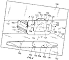
- Figure 2 illustrates a perspective view of the latch assembly 108 positioned over the slot case 106, according to an example of the present disclosure.
- the slot case 106 is secured to the tab 114 extending outwardly (for example, downwardly) from the edge wall 110 of the first composite panel 100.
- a first latch assembly 108 can be on a first side 116 of the tab 114
- a second latch assembly 108 can be on a second side 118 (opposite from the first side 116) of the tab 114.
- the latch assembly 108 includes a base 120 that secures over a face 122 of the tab 114.
- the latch assembly 108 further includes a first latch 124 and a second latch 126 secured to the base 120, such as by a cover 128.
- a lock 130 is disposed between the first latch 124 and the second latch 126.
- the first side 116 of the tab 114 can be bonded to the base 120.
- a peak and stick adhesive can be applied to tab 114.
- an epoxy can be used.
- the first latch 124, the second latch 126, and the lock 130 can be retained within reciprocal channels, recesses, grooves, or the like formed in the base 120.
- the latch assembly 108 does not include the cover 128.
- the first latch 124 includes an upright beam 132 connected to an insertion beam 134. As shown, the upright beam 132 can be perpendicular or substantially perpendicular (such as within 10 degrees or less) to the insertion beam 134.
- the second latch 126 includes an upright beam 132 connected to an insertion beam 134.
- the upright beam 132 can be perpendicular or substantially perpendicular to the insertion beam 134.
- the first latch 124 and the second latch 126 face away from each other.
- the insertion beam 134 of the first latch 124 extends away from the upright beam 132 in the direction of arrow A
- the insertion beam 134 of the second latch 126 extends outwardly away from the upright beam 132 in the direction of arrow B, which is opposite from the direction of arrow A.
- the lock 130 is C-shaped, and includes a first prong 140 connected to an opposite second prong 142 by a cross beam 144.
- a channel 146 is formed between the first prong 140, the second prong 142, and the cross beam 144.
- the slot case 106 is recessed into the second composite panel 102.
- the slot case 106 can be secured inside a reciprocal channel formed in the second composite panel 102, such as by adhesive.
- the slot case 106 is sized and shaped to receive and retain the tab 114.
- the slot case 106 includes lateral walls 150 connected to an end walls 152 and a base (hidden from view in Figure 2 ).
- a tab chamber 154 is defined between the lateral walls 150, the end walls 152, and the base.
- An insertion recess 156 is formed in each lateral wall 150. Strikes 158 are formed in the lateral walls 150 and connect to the insertion recess 156.
- the tab 114 is not disposed in the tab chamber 154. Instead, as shown in Figure 2 , the first composite panel 100 is first disposed over the second composite panel 102 such that the tab 114 is aligned over the tab chamber 154.
- the latch assembly 108 Before the tab 114 is inserted into the tab chamber 154, the latch assembly 108 is in a first position, such as an extended position, in which the lock 130 separates the first latch 124 from the second latch 126. In order to secure the first composite panel 100 to the second composite panel 102, the first composite panel 100 is urged toward the second composite panel 102 so that the tab 114 moves in the direction of arrow C into the tab chamber 154.
- Figure 3 illustrates a perspective view of the latch assembly 108 positioned over the slot case 106 in which the lock 130 is removed from a space 160 between the first latch 124 and the second latch 126, according to an example of the present disclosure.
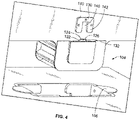
- Figure 4 illustrates a perspective view of the latch assembly 108 in which the first latch 124 and the second latch 126 abut into one another, according to an example of the present disclosure.
- the latch assembly 108 is in a retracted position, in which the insertion beams 134 (shown in Figure 2 ) are within the cover 128, and have a combined width that is less than the width of the insertion recess 156 (shown in Figure 2 ) of the slot case 106.
- latch assembly 108 is able to slide into the tab chamber 154 with the insertion beams 134 sliding into the insertion recess 156.
- the lock 130 can be moved over the upright beams 132 such that the abutting upright beams 132 fit within the channel 146 of the lock 130 and are therefore moveably constrained by the prongs 140 and 142.
- the tab 114 is then inserted into the tab chamber 154, such that the first latch 124 and the second latch 126 slide into the insertion recess 156.
- the latch assemblies 108 on opposite sides of the tab 114 are manipulated in such fashion.
- Figure 5 illustrates a perspective view of the system 104 having the latch assembly 108 in a securing position in relation to the slot case 106, according to an example of the present disclosure.
- the first latch 124 and the second latch 126 are moved (such as slid) away from one another.
- the insertion beams 134 of the first latch 124 and the second latch 126 are moved into respective strikes 158 of the slot case 106.
- the lock 130 is then moved back into the space 160 between the first latch 124 and the second latch 126 to prevent the insertion beams 134 from retreating from the strikes 158.
- the latch assembly 108 is securely coupled to the slot case 106, thereby securing the first composite panel 100 to the second composite panel 102.
- the latch assemblies 108 on opposite sides of the tab 114 are manipulated in such fashion.
- Figure 6 illustrates a perspective view of the first composite panel 100 secured to the second composite panel 102 by the system 104, according to an example of the present disclosure.
- the lock 130 and upper ends of the insertion beams 132 extend above the second composite panel 102 and on sides of the first composite panel 100.
- the lock 130 can be grasped and removed, such that the first latch 124 and the second latch 126 can be moved together, thereby removing the insertion beams 134 from the strikes 158.
- the first composite panel 100 can be easily disconnected from the second composite panel 102, as the first latch 124 and the second latch 126 are no longer securely retained by the strikes 158.
- Figure 7 illustrates a perspective view of a tab of a first composite panel 100 positioned over a slot case 106, according to an example of the present disclosure.
- the strike 158 is formed on the tab 114, and the latch assembly 108 is retained within the slot case 106.
- the strike 158 is disposed on the tab 114 of the first composite panel 100, and the latch assembly 108 includes a first latch 224 and a second latch 226 moveably retained within the slot case 106.
- the strike 158 is a channel defined between an upper protuberance 200 and a lower protuberance 202 outwardly extending from the face of the tab 114.
- the latch assembly 108 includes a first latch 224 and a second latch 226 on opposite sides of an insertion channel 228.
- the first latch 224 and the second latch 226 are spread apart so that respective insertion beams 234 are slidably retained within beam channels 236 outside of the insertion channel 228.
- the tab 114 is then urged into the tab chamber 254 such that the strike 158 is linearly aligned with the beam channels 236.
- first latch 224 and the second latch 226 are slid toward one another, such that the insertion beams 234 are retained within the strike 158.
- Locks (such as portions of a cover of the tab 114) can be positioned between the upright beams 232 of the first latch 224 and the second latch 226 and interior walls 260 of the slot case 106 to ensure that the first latch 224 and the second latch 226 do not inadvertently disengage from the strike 158.
- the exposed positions of the upright beams 232 can include tool-receiving openings 270.
- a tool can be inserted into the tool receiving openings 270 to move the first latch 224 and the second latch 226 between spread positions and securing positions.
- the first latch 224 and the second latch 226 may not include the tool-receiving openings 270.
- Figure 8 illustrates a perspective view of the tab 114 of the first composite panel 100 secured to the slot case 106 of Figure 7 .
- the system 104 is shown in a securing state, in which the insertion beams (indicated with reference sign 134 in present Figure 8 ) of the first latch (indicated with reference sign 124 in present Figure 8 ) and the second latch (indicated with reference sign 126 in present Figure 8 ) are retained within the strike 158 of the tab 114.
- Figure 9 illustrates a perspective view of a tab 114 of a first composite panel 100 positioned over a slot case 106, according to an example of the present disclosure.
- a plurality of strikes 158 are formed on the tab 114.
- a latch assembly 108 includes a single latch 300 slidably retained within reciprocal channels formed in the slot case 106.
- the tab 114 is configured to be inserted into the tab chamber 154, and latching elements 302 of the latch 300 are configured to slide into the strikes 158, similar to as described above.
- the tab 114 can include more or less strikes 158 than shown.
- the latch 300 can include more or less latching elements 302 than shown.
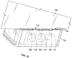
- Figure 10 illustrates a perspective view of the tab 114 of the first composite panel 100 secured to the slot case of Figure 9 . As shown, the latching elements 302 are retained within the strikes 158, thereby securely retaining the tab 114 to the slot case 106.
- Figure 11 illustrates a perspective exploded view of a composite panel 400, according to an example of the present disclosure.
- the first composite panel 100 and the second composite panel 102 can be configured as the composite panel 400.
- the composite panel 400 includes a core 402 sandwiched between an inner skin 404 and an outer skin 408.
- the core 402 is a honeycomb core that includes a plurality of interconnected honeycomb cells 420.
- the core 402 may be a solid layer or porous foam layer.
- the core 402 may be formed of aramid fibers, and/or polyamides, for example.
- the inner skin 404 and the outer skin 408 may be or include one or more pre-impregnated epoxy resin layers that include fibers, such as fiberglass, graphite, Kevlar, and/or the like.
- the inner skin 404 and the outer skin 408 may be identical to one another. In at least one other example, the inner skin 404 and the outer skin 408 may include more or less layers than one another.
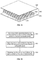
- Figure 12 illustrates a flow chart of a method for securing a first composite panel to a second composite panel, according to an example of the present disclosure.
- the method includes securing, at 500, a latch assembly having one or more latches to one of the first composite panel or the second composite panel; securing, at 502, one or more strikes to the other of the first composite panel or the second composite panel; and retaining, at 504, by the one or more strikes, at least a portion of the one or more latches.
- the method includes bonding a slot case to the second composite panel, for example.
- examples of the present disclosure provide systems and methods for efficiently and effectively securing composite panels together. Further, examples of the present disclosure provide systems and methods for securing composite panels together before and during a curing process with less adhesive than prior connectors.
- a structure, limitation, or element that is "configured to” perform a task or operation is particularly structurally formed, constructed, or adapted in a manner corresponding to the task or operation.
- an object that is merely capable of being modified to perform the task or operation is not “configured to” perform the task or operation as used herein.
Landscapes
- Engineering & Computer Science (AREA)
- Mechanical Engineering (AREA)
- General Engineering & Computer Science (AREA)
- Architecture (AREA)
- Civil Engineering (AREA)
- Structural Engineering (AREA)
- Physics & Mathematics (AREA)
- Electromagnetism (AREA)
- Connection Of Plates (AREA)
Abstract
Description
- Examples of the present disclosure generally relate to composite panels, and, more particularly, to systems and methods for coupling composite panels together.
- Various structures are formed from composite materials. For example, portions of aircraft, such as wings, may be formed from composite materials. The composite material may be or include a polymer matrix reinforced with fibers. The fibers may be bound together with polymers, such as epoxy. Known fibers include glass, carbon, basalt, aramid, or the like.
- Typically, composite panels are bonded together during a manufacturing process. Slot cases are secured to a composite panel through bonding. The slot cases are then bonded to a connecting structure of another composite panel to secure the composite panels together prior to and during a curing process, for example. For example, a tab is inserted into the slot case, and adhesive is applied therebetween to secure the tab to the slot case.
- As can be appreciated, the process of securing the composite panels together typically requires multiple bonding steps in relation to the slot cases. As such, the process of securing the composite panels together can be labor and time intensive. Further, the adhesive between the tab and the slot case may undesirably overflow onto other portions of the composite panels, cause portions of the composite panels to bulge, and/or the like.
- A need exists for a system and a method for efficiently and effectively securing composite panels together. Further, a need exists for a system and a method for securing composite panels together before and during a curing process that uses less adhesive.
- With those needs in mind, certain examples of the present disclosure provide a system for securing a first composite panel to a second composite panel. The system includes a latch assembly having one or more latches. The latch assembly is configured to be secured to one of the first composite panel or the second composite panel. One or more strikes are configured to retain at least a portion of the one or more latches. The one or more strikes are configured to be secured to the other of the first composite panel or the second composite panel.
- In at least one example, the latch assembly is configured to secure a tab of the first composite panel to a slot case of the second composite panel without adhesive.
- In at least one example, the latch assembly is disposed on one of a tab of the first composite panel or a slot case of the second composite panel. The one or more strikes are disposed on the other of the tab of the first composite panel or the slot case of the second composite panel.
- As an example, the latch assembly includes a first latch, a second latch, and a lock disposed between the first latch and the second latch. As a further example, the lock is removable from a space between the first latch and the second latch. The first latch and the second latch are moveable when the lock is removed from the space.
- As an example, each of the first latch and the second latch includes an upright beam, and an insertion beam connected to the upright beam. The insertion beam is configured to be moved into and out of the one or more strikes.
- As an example, the lock includes a first prong connected to a second prong by a cross beam. A channel is formed between the first prong, the second prong, and the cross beam. Portions of the first latch and the second latch are retained within the channel when the first latch abuts the second latch.
- As an example, the one or more strikes are disposed on a tab of the first composite panel. The latch assembly includes a first latch and a second latch moveably retained within a slot case of the second composite panel.
- As an example, the one or more strikes include a plurality of strikes disposed on the first composite panel. The latch assembly includes a single latch having a plurality of latching elements within a slot case of the second composite panel.
- In at least one example, each of the first composite panel and the second composite panel comprises a honeycomb core sandwiched between an inner skin and an outer skin.
- Certain examples of the present disclosure provide a method for securing a first composite panel to a second composite panel. The method includes securing a latch assembly having one or more latches to one of the first composite panel or the second composite panel; securing one or more strikes to the other of the first composite panel or the second composite panel; and retaining, by the one or more strikes, at least a portion of the one or more latches.
- Certain examples of the present disclosure provide a system including a first composite panel, a second composite panel secured to the first composite panel in an orthogonal orientation, a latch assembly having one or more latches (wherein the latch assembly is secured to one of the first composite panel or the second composite panel), and one or more strikes configured to retain at least a portion of the one or more latches (wherein the one or more strikes are secured to the other of the first composite panel or the second composite panel).
-
-
Figure 1 illustrates perspective view of a first composite panel coupled to a second composite panel. -
Figure 2 illustrates a perspective view of a latch assembly positioned over a slot case. -
Figure 3 illustrates a perspective view of a latch assembly positioned over a slot case in which a lock is removed from a space between a first latch and a second latch. -
Figure 4 illustrates a perspective view of the latch assembly in which the first latch and the second latch abut into one another. -
Figure 5 illustrates a perspective view of the system having the latch assembly in a securing position in relation to the slot case. -
Figure 6 illustrates an enlarged perspective view of the first composite panel secured to the second composite panel by the system. -
Figure 7 illustrates a perspective view of a tab of a first composite panel positioned over a slot case. -
Figure 8 illustrates a perspective view of the tab of the first composite panel secured to the slot case ofFigure 7 . -
Figure 9 illustrates a perspective view of a tab of a first composite panel positioned over a slot case. -
Figure 10 illustrates a perspective view of the tab of the first composite panel secured to the slot case ofFigure 9 . -
Figure 11 illustrates a perspective exploded view a composite panel. -
Figure 12 illustrates a flow chart of a method for securing a first composite panel to a second composite panel. - The foregoing summary, as well as the following detailed description of certain examples, will be better understood when read in conjunction with the appended drawings. As used herein, an element or step recited in the singular and preceded by the word "a" or "an" should be understood as not necessarily excluding the plural of the elements or steps. Further, references to "one example" are not intended to be interpreted as excluding the existence of additional examples that also incorporate the recited features. Moreover, unless explicitly stated to the contrary, examples "comprising" or "having" an element or a plurality of elements having a particular property may include additional elements not having that property.
- As noted, a slot case can be used to connect a composite panel to another composite panel. However, the slot case is typically adhesively bonded to a first composite panel, and then a tab of a second composite panel is then adhesively bonded to the slot case, thereby increasing manufacturing time and cost.
- Examples of the present disclosure provide a system and a method for coupling composite panels together without the need for adhesively bonding a tab to a slot case. The system and method include a mechanical slide lock that secures the tab to the slot case, thereby allowing an assembly including the composite panels to be efficiently and effectively built, and easily disassembled, if needed. In at least one example, the mechanical slide lock includes one or more latches that are configured to slidably couple to one or more strikes. The latches can be on a tab of a first composite panel, and the strikes can be part of a slot case or receive of a second composite panel, or vice versa.
- In at least one example, one or more sliding latches are integrated into either the slot case or a tab panel of a composite panel. Locking keys can hold the latches in a first position before an assembly process, and ensure they remain in a locked second position after the assembly process.
-
Figure 1 illustrates perspective view of a firstcomposite panel 100 coupled to a secondcomposite panel 102, according to an example of the present disclosure. Asystem 104 secures the firstcomposite panel 100 to the secondcomposite panel 102. As shown, the firstcomposite panel 100 is orthogonal to the secondcomposite panel 102. For example, the firstcomposite panel 100 is perpendicular or substantially perpendicular (for example, +/- 5 degrees) to the secondcomposite panel 102. In at least one example, thesystem 104 secures the firstcomposite panel 100 to the secondcomposite panel 102 in an orthogonal orientation. - The
system 104 includes a receiver orslot case 106 secured to the second composite panel 102 (or optionally, the first composite panel 100), and alatch assembly 108 secured to the first composite panel 100 (or optionally, the second composite panel 102). - The
latch assembly 108 can be secured to a tab extending outwardly from aperimeter edge wall 110 of the firstcomposite panel 100. Theslot case 106 can be formed in (such as integrally recessed into) anouter face wall 112 of the secondcomposite panel 102. As shown, thesystem 104 secures the firstcomposite panel 100 to the secondcomposite panel 102 in an edge-to-face fashion. Optionally, theslot case 106 can be formed in theperimeter edge wall 110, and thelatch assembly 108 can be formed in theouter face wall 112. As another example, thelatch assembly 108 and theslot case 106 can be formed in perimeter edge walls of thecomposite panels composite panel 100 to the secondcomposite panel 102 in an edge-to-edge fashion. As another example, the latch assembly and theslot case 106 can be formed in outer face walls of thecomposite panels composite panel 100 to the secondcomposite panel 102 in a face-to-face fashion. - As described herein, the
system 104 includes a latch assembly having at least one latch that is configured to latchably couple to at least one strike to secure the tab of the firstcomposite panel 100 to theslot case 106 of the secondcomposite panel assembly 100. A plurality ofsystems 104 can be used to secure the firstcomposite panel 100 to the secondcomposite panel 102, such as along a seam therebetween. In at least one example, thesystem 104 secures thecomposite panels - The
system 104 secures the firstcomposite panel 100 to the secondcomposite panel 102, and includes a latch assembly having one or more latches. The latch assembly is secured to one of the firstcomposite panel 100 or the secondcomposite panel 102. A strike is configured to retain at least a portion of the one or more latches. The strike is secured to the other of the firstcomposite panel 100 or the secondcomposite panel 102. -
Figure 2 illustrates a perspective view of thelatch assembly 108 positioned over theslot case 106, according to an example of the present disclosure. Theslot case 106 is secured to thetab 114 extending outwardly (for example, downwardly) from theedge wall 110 of the firstcomposite panel 100. As shown, afirst latch assembly 108 can be on afirst side 116 of thetab 114, and asecond latch assembly 108 can be on a second side 118 (opposite from the first side 116) of thetab 114. - The
latch assembly 108 includes a base 120 that secures over aface 122 of thetab 114. Thelatch assembly 108 further includes afirst latch 124 and asecond latch 126 secured to thebase 120, such as by acover 128. Alock 130 is disposed between thefirst latch 124 and thesecond latch 126. In at least one example, thefirst side 116 of thetab 114 can be bonded to thebase 120. Optionally, a peak and stick adhesive can be applied totab 114. As another example, an epoxy can be used. - In at least one example, the
first latch 124, thesecond latch 126, and thelock 130 can be retained within reciprocal channels, recesses, grooves, or the like formed in thebase 120. Optionally, thelatch assembly 108 does not include thecover 128. - The
first latch 124 includes anupright beam 132 connected to aninsertion beam 134. As shown, theupright beam 132 can be perpendicular or substantially perpendicular (such as within 10 degrees or less) to theinsertion beam 134. - Similarly, the
second latch 126 includes anupright beam 132 connected to aninsertion beam 134. Theupright beam 132 can be perpendicular or substantially perpendicular to theinsertion beam 134. - The
first latch 124 and thesecond latch 126 face away from each other. For example, theinsertion beam 134 of thefirst latch 124 extends away from theupright beam 132 in the direction of arrow A, while theinsertion beam 134 of thesecond latch 126 extends outwardly away from theupright beam 132 in the direction of arrow B, which is opposite from the direction of arrow A. - The
lock 130 is C-shaped, and includes afirst prong 140 connected to an oppositesecond prong 142 by across beam 144. Achannel 146 is formed between thefirst prong 140, thesecond prong 142, and thecross beam 144. - The
slot case 106 is recessed into the secondcomposite panel 102. Theslot case 106 can be secured inside a reciprocal channel formed in the secondcomposite panel 102, such as by adhesive. Theslot case 106 is sized and shaped to receive and retain thetab 114. Theslot case 106 includeslateral walls 150 connected to anend walls 152 and a base (hidden from view inFigure 2 ). Atab chamber 154 is defined between thelateral walls 150, theend walls 152, and the base. - An
insertion recess 156 is formed in eachlateral wall 150.Strikes 158 are formed in thelateral walls 150 and connect to theinsertion recess 156. - In a disconnected or uncoupled state, the
tab 114 is not disposed in thetab chamber 154. Instead, as shown inFigure 2 , the firstcomposite panel 100 is first disposed over the secondcomposite panel 102 such that thetab 114 is aligned over thetab chamber 154. - Before the
tab 114 is inserted into thetab chamber 154, thelatch assembly 108 is in a first position, such as an extended position, in which thelock 130 separates thefirst latch 124 from thesecond latch 126. In order to secure the firstcomposite panel 100 to the secondcomposite panel 102, the firstcomposite panel 100 is urged toward the secondcomposite panel 102 so that thetab 114 moves in the direction of arrow C into thetab chamber 154. -
Figure 3 illustrates a perspective view of thelatch assembly 108 positioned over theslot case 106 in which thelock 130 is removed from aspace 160 between thefirst latch 124 and thesecond latch 126, according to an example of the present disclosure. Before thetab 114 is inserted into thetab chamber 154 of theslot case 106, thelock 130 is removed from thespace 160. After thelock 130 is removed from thespace 160, thefirst latch 124 and thesecond latch 126 are moved (such as slid) together. In at least one example, thelatch assemblies 108 on opposite sides of thetab 114 are manipulated in such fashion. -
Figure 4 illustrates a perspective view of thelatch assembly 108 in which thefirst latch 124 and thesecond latch 126 abut into one another, according to an example of the present disclosure. When thefirst latch 124 and thesecond latch 126 abut against one another, the respectiveupright beams 132 abut against one another. As such, thelatch assembly 108 is in a retracted position, in which the insertion beams 134 (shown inFigure 2 ) are within thecover 128, and have a combined width that is less than the width of the insertion recess 156 (shown inFigure 2 ) of theslot case 106. As such,latch assembly 108 is able to slide into thetab chamber 154 with the insertion beams 134 sliding into theinsertion recess 156. Thelock 130 can be moved over theupright beams 132 such that the abuttingupright beams 132 fit within thechannel 146 of thelock 130 and are therefore moveably constrained by theprongs tab 114 is then inserted into thetab chamber 154, such that thefirst latch 124 and thesecond latch 126 slide into theinsertion recess 156. In at least one example, thelatch assemblies 108 on opposite sides of thetab 114 are manipulated in such fashion. -
Figure 5 illustrates a perspective view of thesystem 104 having thelatch assembly 108 in a securing position in relation to theslot case 106, according to an example of the present disclosure. For the sake of clarity, portions of thesystem 104 are shown transparent. After thelatch assembly 108 is inserted into theinsertion recess 156, thefirst latch 124 and thesecond latch 126 are moved (such as slid) away from one another. During such motion, the insertion beams 134 of thefirst latch 124 and thesecond latch 126 are moved intorespective strikes 158 of theslot case 106. Thelock 130 is then moved back into thespace 160 between thefirst latch 124 and thesecond latch 126 to prevent the insertion beams 134 from retreating from thestrikes 158. In this manner, thelatch assembly 108 is securely coupled to theslot case 106, thereby securing the firstcomposite panel 100 to the secondcomposite panel 102. In at least one example, thelatch assemblies 108 on opposite sides of thetab 114 are manipulated in such fashion. -
Figure 6 illustrates a perspective view of the firstcomposite panel 100 secured to the secondcomposite panel 102 by thesystem 104, according to an example of the present disclosure. Referring toFigures 1-6 , as shown, thelock 130 and upper ends of the insertion beams 132 extend above the secondcomposite panel 102 and on sides of the firstcomposite panel 100. As such, thelock 130 can be grasped and removed, such that thefirst latch 124 and thesecond latch 126 can be moved together, thereby removing the insertion beams 134 from thestrikes 158. Accordingly, the firstcomposite panel 100 can be easily disconnected from the secondcomposite panel 102, as thefirst latch 124 and thesecond latch 126 are no longer securely retained by thestrikes 158. -
Figure 7 illustrates a perspective view of a tab of a firstcomposite panel 100 positioned over aslot case 106, according to an example of the present disclosure. In this example, thestrike 158 is formed on thetab 114, and thelatch assembly 108 is retained within theslot case 106. - For example, the
strike 158 is disposed on thetab 114 of the firstcomposite panel 100, and thelatch assembly 108 includes afirst latch 224 and asecond latch 226 moveably retained within theslot case 106. - For example, the
strike 158 is a channel defined between anupper protuberance 200 and alower protuberance 202 outwardly extending from the face of thetab 114. Thelatch assembly 108 includes afirst latch 224 and asecond latch 226 on opposite sides of aninsertion channel 228. In order to the secure thetab 114 to theslot case 106, thefirst latch 224 and thesecond latch 226 are spread apart so thatrespective insertion beams 234 are slidably retained withinbeam channels 236 outside of theinsertion channel 228. Thetab 114 is then urged into thetab chamber 254 such that thestrike 158 is linearly aligned with thebeam channels 236. - In order to secure the
latch assembly 108 to thetab 114, thefirst latch 224 and thesecond latch 226 are slid toward one another, such that the insertion beams 234 are retained within thestrike 158. Locks (such as portions of a cover of the tab 114) can be positioned between theupright beams 232 of thefirst latch 224 and thesecond latch 226 andinterior walls 260 of theslot case 106 to ensure that thefirst latch 224 and thesecond latch 226 do not inadvertently disengage from thestrike 158. - In at least one example, the exposed positions of the
upright beams 232 can include tool-receivingopenings 270. A tool can be inserted into thetool receiving openings 270 to move thefirst latch 224 and thesecond latch 226 between spread positions and securing positions. Optionally, thefirst latch 224 and thesecond latch 226 may not include the tool-receivingopenings 270. -
Figure 8 illustrates a perspective view of thetab 114 of the firstcomposite panel 100 secured to theslot case 106 ofFigure 7 . Thesystem 104 is shown in a securing state, in which the insertion beams (indicated withreference sign 134 in presentFigure 8 ) of the first latch (indicated withreference sign 124 in presentFigure 8 ) and the second latch (indicated withreference sign 126 in presentFigure 8 ) are retained within thestrike 158 of thetab 114. -
Figure 9 illustrates a perspective view of atab 114 of a firstcomposite panel 100 positioned over aslot case 106, according to an example of the present disclosure. In this example, a plurality ofstrikes 158 are formed on thetab 114. Alatch assembly 108 includes asingle latch 300 slidably retained within reciprocal channels formed in theslot case 106. Thetab 114 is configured to be inserted into thetab chamber 154, and latchingelements 302 of thelatch 300 are configured to slide into thestrikes 158, similar to as described above. Thetab 114 can include more orless strikes 158 than shown. Additionally, thelatch 300 can include more or lesslatching elements 302 than shown. -
Figure 10 illustrates a perspective view of thetab 114 of the firstcomposite panel 100 secured to the slot case ofFigure 9 . As shown, the latchingelements 302 are retained within thestrikes 158, thereby securely retaining thetab 114 to theslot case 106. -
Figure 11 illustrates a perspective exploded view of acomposite panel 400, according to an example of the present disclosure. The firstcomposite panel 100 and the secondcomposite panel 102 can be configured as thecomposite panel 400. In at least one example, thecomposite panel 400 includes a core 402 sandwiched between aninner skin 404 and anouter skin 408. - In at least one example, the
core 402 is a honeycomb core that includes a plurality ofinterconnected honeycomb cells 420. In at least one other example, thecore 402 may be a solid layer or porous foam layer. Thecore 402 may be formed of aramid fibers, and/or polyamides, for example. Theinner skin 404 and theouter skin 408 may be or include one or more pre-impregnated epoxy resin layers that include fibers, such as fiberglass, graphite, Kevlar, and/or the like. Theinner skin 404 and theouter skin 408 may be identical to one another. In at least one other example, theinner skin 404 and theouter skin 408 may include more or less layers than one another. -
Figure 12 illustrates a flow chart of a method for securing a first composite panel to a second composite panel, according to an example of the present disclosure. The method includes securing, at 500, a latch assembly having one or more latches to one of the first composite panel or the second composite panel; securing, at 502, one or more strikes to the other of the first composite panel or the second composite panel; and retaining, at 504, by the one or more strikes, at least a portion of the one or more latches. In at least one example, the method includes bonding a slot case to the second composite panel, for example. - As described herein, examples of the present disclosure provide systems and methods for efficiently and effectively securing composite panels together. Further, examples of the present disclosure provide systems and methods for securing composite panels together before and during a curing process with less adhesive than prior connectors.
- Further, the disclosure comprises examples according to the following clauses:
- Clause 1. A system for securing a first composite panel to a second composite panel, the system comprising:
- a latch assembly having one or more latches, wherein the latch assembly is configured to be secured to one of the first composite panel or the second composite panel; and
- one or more strikes configured to retain at least a portion of the one or more latches, wherein the one or more strikes are configured to be secured to the other of the first composite panel or the second composite panel.
-
Clause 2. The system of Clause 1, wherein the latch assembly is configured to secure a tab of the first composite panel to a slot case of the second composite panel without adhesive. - Clause 3. The system of
Clauses 1 or 2, wherein the latch assembly is disposed on one of a tab of the first composite panel or a slot case of the second composite panel , and wherein the one or more strikes are disposed on the other of the tab of the first composite panel or the slot case of the second composite panel. - Clause 4. The system of any of Clauses 1-3, wherein the latch assembly comprises:
- a first latch;
- a second latch; and
- a lock disposed between the first latch and the second latch.
- Clause 5. The system of Clause 4, wherein the lock is removable from a space between the first latch and the second latch, and wherein the first latch and the second latch are moveable when the lock is removed from the space.
- Clause 6. The system of Clauses 4 or 5, wherein each of the first latch and the second latch comprises:
- an upright beam; and
- an insertion beam connected to the upright beam, wherein the insertion beam is configured to be moved into and out of the one or more strikes.
- Clause 7. The system of any of Clauses 4-6, wherein the lock comprises a first prong connected to a second prong by a cross beam, wherein a channel is formed between the first prong, the second prong, and the cross beam, wherein portions of the first latch and the second latch are retained within the channel when the first latch abuts the second latch.
- Clause 8. The system of any of any of Clauses 1-7, wherein the one or more strikes are disposed on a tab of the first composite panel, and wherein the latch assembly comprises a first latch and a second latch moveably retained within a slot case of the second composite panel.
- Clause 9. The system of an of any of Clauses 1-8, wherein the one or more strikes comprise a plurality of strikes disposed on the first composite panel, and wherein the latch assembly comprises a single latch having a plurality of latching elements within a slot case of the second composite panel.
- Clause 10. The system of any of clauses 1-9, wherein each of the first composite panel and the second composite panel comprises a honeycomb core sandwiched between an inner skin and an outer skin.
- Clause 11. A method for securing a first composite panel to a second composite panel, the method comprising:
- securing a latch assembly having one or more latches to one of the first composite panel or the second composite panel;
- securing one or more strikes to the other of the first composite panel or the second composite panel; and
- retaining, by the one or more strikes, at least a portion of the one or more latches.
- Clause 12. The method of Clause 11, wherein said securing the latch assembly comprises securing, by the latch assembly, a tab of the first composite panel to a slot case of the second composite panel without adhesive.
- Clause 13. The method of Clauses 11 or 12, wherein said securing the latch assembly comprises disposing the latch assembly on one of a tab of the first composite panel or a slot case of the second composite panel , and wherein said securing the one or more strikes comprises disposing the one or more strikes on the other of the tab of the first composite panel or the slot case of the second composite panel.
- Clause 14. An assembly of composite panels, said assembly comprising:
- a first composite panel;
- a second composite panel secured to the first composite panel in an orthogonal orientation;
- a latch assembly having one or more latches, wherein the latch assembly is secured to one of the first composite panel or the second composite panel; and one or more strikes configured to retain at least a portion of the one or more latches, wherein the one or more strikes are secured to the other of the first composite panel or the second composite panel.
- Clause 15. The system of Clause 14, wherein the latch assembly is configured to secure a tab of the first composite panel to a slot case of the second composite panel without adhesive.
- Clause 16. The system of clauses 14 or 15, wherein the latch assembly is disposed on one of a tab of the first composite panel or a slot case of the second composite panel , and wherein the one or more strikes are disposed on the other of the tab of the first composite panel or the slot case of the second composite panel.
- Clause 17. The system of any of clauses 14-16, wherein the latch assembly comprises:
- a first latch;
- a second latch; and
- a lock disposed between the first latch and the second latch.
- Clause 18. The system of Clause 17, wherein the lock is removable from a space between the first latch and the second latch, and wherein the first latch and the second latch are moveable when the lock is removed from the space, wherein each of the first latch and the second latch comprises an upright beam, and an insertion beam connected to the upright beam, wherein the insertion beam is configured to be moved into and out of the one or more strikes, wherein the lock comprises a first prong connected to a second prong by a cross beam, wherein a channel is formed between the first prong, the second prong, and the cross beam, wherein portions of the first latch and the second latch are retained within the channel when the first latch abuts the second latch.
- Clause 19. The system of any of Clauses 14-18, wherein the one or more strikes are disposed on a tab of the first composite panel, and wherein the latch assembly comprises a first latch and a second latch moveably retained within a slot case of the second composite panel.
- Clause 20. The system of any of Clauses 14-19, wherein each of the first composite panel and the second composite panel comprises a honeycomb core sandwiched between an inner skin and an outer skin.
- While various spatial and directional terms, such as top, bottom, lower, mid, lateral, horizontal, vertical, front and the like can be used to describe examples of the present disclosure, it is understood that such terms are merely used with respect to the orientations shown in the drawings. The orientations can be inverted, rotated, or otherwise changed, such that an upper portion is a lower portion, and vice versa, horizontal becomes vertical, and the like.
- As used herein, a structure, limitation, or element that is "configured to" perform a task or operation is particularly structurally formed, constructed, or adapted in a manner corresponding to the task or operation. For purposes of clarity and the avoidance of doubt, an object that is merely capable of being modified to perform the task or operation is not "configured to" perform the task or operation as used herein.
- It is to be understood that the above description is intended to be illustrative, and not restrictive. For example, the above-described examples (and/or aspects thereof) can be used in combination with each other. In addition, many modifications can be made to adapt a particular situation or material to the teachings of the various examples of the disclosure without departing from their scope. While the dimensions and types of materials described herein are intended to define the parameters of the various examples of the disclosure, the examples are by no means limiting and are exemplary examples. Many other examples will be apparent to those of skill in the art upon reviewing the above description. The scope of the various examples of the disclosure should, therefore, be determined with reference to the appended claims, along with the full scope of equivalents to which such claims are entitled. In the appended claims and the detailed description herein, the terms "including" and "in which" are used as the plain-English equivalents of the respective terms "comprising" and "wherein." Moreover, the terms "first," "second," and "third," etc. are used merely as labels, and are not intended to impose numerical requirements on their objects. This written description uses examples to disclose the various examples of the disclosure, including the best mode, and also to enable any person skilled in the art to practice the various examples of the disclosure, including making and using any devices or systems and performing any incorporated methods. The patentable scope of the various examples of the disclosure is defined by the claims, and can include other examples that occur to those skilled in the art. Such other examples are intended to be within the scope of the claims if the examples have structural elements that do not differ from the literal language of the claims, or if the examples include equivalent structural elements with insubstantial differences from the literal language of the claims.
Claims (15)
- A system (104) for securing a first composite panel (100) to a second composite panel (102), the system comprising:a latch assembly (108) having one or more latches (124, 126), wherein the latch assembly (108) is configured to be secured to one of the first composite panel (100) or the second composite panel (102); andone or more strikes (158) configured to retain at least a portion of the one or more latches (124, 126), wherein the one or more strikes (158) are configured to be secured to the other of the first composite panel (100) or the second composite panel (102).
- The system of claim 1, wherein the latch assembly (108) is configured to secure a tab (114) of the first composite panel (100) to a slot case (106) of the second composite panel (102) without adhesive.
- The system of claim 1 or 2, wherein the latch assembly (108) is disposed on one of a tab (114) of the first composite panel (100) or a slot case (106) of the second composite panel (102), and wherein the one or more strikes (158) are disposed on the other of the tab (114) of the first composite panel (100) or the slot case (106) of the second composite panel (102).
- The system of claim 1, 2, or 3, wherein the latch assembly (108) comprises:a first latch (124);a second latch (126); anda lock (130) disposed between the first latch (124) and the second latch (126).
- The system of claim 4, wherein the lock (130) is removable from a space between the first latch (124) and the second latch (126), and wherein the first latch (124) and the second latch (126) are moveable when the lock (130) is removed from the space.
- The system of claim 4 or 5, wherein each of the first latch (124) and the second latch (126) comprises:an upright beam (132); andan insertion beam (134) connected to the upright beam (132), wherein the insertion beam (134) is configured to be moved into and out of the one or more strikes (158).
- The system of claim 4, 5, or 6, wherein the lock (130) comprises a first prong (140) connected to a second prong (142) by a cross beam (144), wherein a channel (146) is formed between the first prong (140), the second prong (142), and the cross beam (144), wherein portions of the first latch (124) and the second latch (126) are retained within the channel (146) when the first latch (124) abuts the second latch (126).
- The system of any one of claims 1-7, wherein the one or more strikes (158) are disposed on a tab (114) of the first composite panel (100), and wherein the latch assembly (108) comprises a first latch (124) and a second latch (126) moveably retained within a slot case (106) of the second composite panel (102).
- The system of any one of claims 1-8, wherein the one or more strikes (158) comprise a plurality of strikes (158) disposed on the first composite panel (100), and wherein the latch assembly (108) comprises a single latch (300) having a plurality of latching elements (300) within a slot case (106) of the second composite panel (102).
- The system of any one of claims 1-9, further comprising a first composite panel (100) and a second composite panel (102), wherein each of the first composite panel (100) and the second composite panel (102) comprises a honeycomb core (402) sandwiched between an inner skin (404) and an outer skin (408).
- A method for securing a first composite panel (100) to a second composite panel (102), the method comprising:securing a latch assembly (108) having one or more latches (124, 126) to one of the first composite panel (100) or the second composite panel (102);securing one or more strikes (158) to the other of the first composite panel (100) or the second composite panel (102); andretaining, by the one or more strikes (158), at least a portion of the one or more latches (124, 126).
- The method of claim 11, wherein said securing the latch assembly (108) comprises securing, by the latch assembly (108), a tab (114) of the first composite panel (100) to a slot case (106) of the second composite panel (102) without adhesive.
- The method of claim 11 or 12, wherein said securing the latch assembly (108) comprises disposing the latch assembly (108) on one of a tab (114) of the first composite panel (100) or a slot case (106) of the second composite panel (102), and wherein said securing the one or more strikes (158) comprises disposing the one or more strikes (158) on the other of the tab (114) of the first composite panel (100) or the slot case (106) of the second composite panel (102).
- An assembly of composite panels (100, 102), said assembly comprising:a first composite panel (100);a second composite panel (102) secure to the first composite panel (100) in an orthogonal orientation;a system (104) for securing the first composite panel (100) to the second composite panel according to any one of claims 1 to 9.
- The assembly of claim 14, wherein the latch assembly (108) is configured to secure a tab (114) of the first composite panel (100) to a slot case (106) of the second composite panel (102) without adhesive.
Applications Claiming Priority (1)
| Application Number | Priority Date | Filing Date | Title |
|---|---|---|---|
| US202163147834P | 2021-02-10 | 2021-02-10 |
Publications (2)
| Publication Number | Publication Date |
|---|---|
| EP4043189A1 true EP4043189A1 (en) | 2022-08-17 |
| EP4043189B1 EP4043189B1 (en) | 2024-08-14 |
Family
ID=80222169
Family Applications (1)
| Application Number | Title | Priority Date | Filing Date |
|---|---|---|---|
| EP22155358.9A Active EP4043189B1 (en) | 2021-02-10 | 2022-02-07 | Systems and methods for coupling composite panels |
Country Status (4)
| Country | Link |
|---|---|
| US (1) | US11773585B2 (en) |
| EP (1) | EP4043189B1 (en) |
| JP (1) | JP7857108B2 (en) |
| CN (1) | CN114909371A (en) |
Citations (2)
| Publication number | Priority date | Publication date | Assignee | Title |
|---|---|---|---|---|
| US20180051731A1 (en) * | 2015-03-02 | 2018-02-22 | The Boeing Company | Panel systems and methods of assembling panel systems |
| US20200217342A1 (en) * | 2019-01-05 | 2020-07-09 | The Boeing Company | Method and apparatus for joining composite panels |
Family Cites Families (30)
| Publication number | Priority date | Publication date | Assignee | Title |
|---|---|---|---|---|
| US2340864A (en) * | 1941-12-04 | 1944-02-08 | Carpenter Miles Harold | Fastening means for building construction |
| US2581816A (en) * | 1948-08-17 | 1952-01-08 | Simmons Fastener Corp | Fastener for butt joints |
| US3280522A (en) * | 1963-09-16 | 1966-10-25 | Dow Chemical Co | Building panels and fastener means therefor |
| US3363382A (en) * | 1965-09-03 | 1968-01-16 | Dow Chemical Co | Meshing panels with interfitting expandable locking strips |
| DE1650975A1 (en) * | 1968-01-26 | 1970-10-22 | Johannes Jankowski | Device for connecting or connecting components |
| JPS5746108U (en) * | 1980-08-30 | 1982-03-13 | ||
| US5424118A (en) * | 1994-01-25 | 1995-06-13 | Mid-South Industries, Inc. | Interlocking insulative panel construction |
| US5480117A (en) * | 1994-04-28 | 1996-01-02 | Fleming, Iii; Joseph C. | Mounting bracket for wall panel locks |
| US5452925A (en) * | 1994-06-30 | 1995-09-26 | Huang; Chien F. | Tightening latching device |
| US5678948A (en) * | 1995-12-07 | 1997-10-21 | B. Walter And Co., Inc. | Selectively lockable and horizontally and vertically aligning latch for furniture parts |
| JPH1037915A (en) * | 1996-07-26 | 1998-02-13 | Alpine Electron Inc | Detachable device |
| US6199427B1 (en) * | 1997-12-04 | 2001-03-13 | Intercomp Company | Apparatus and method for testing leaf springs |
| US6634077B2 (en) * | 2001-07-20 | 2003-10-21 | Affordable Building Systems | Combined connecting and alignment method for composite fiber building panels |
| GB2380515B (en) * | 2001-10-04 | 2005-12-07 | Kenmark Ind Co Ltd | Boards combination structure |
| US20060156671A1 (en) * | 2005-01-20 | 2006-07-20 | Robert Montague | Apparatus and method for aligning and connecting building panels in close proximity |
| EP1990549A1 (en) * | 2007-05-08 | 2008-11-12 | Franz Baur | Connecting device and method for creating a connection between a first component and a second component |
| US20090199497A1 (en) * | 2007-08-28 | 2009-08-13 | Wrightman Robert A | Log wall connector system |
| US20090241460A1 (en) * | 2008-03-26 | 2009-10-01 | Charles Beaulieu | Fastening Device Template |
| US8333049B2 (en) * | 2008-07-07 | 2012-12-18 | Provia Door, Inc. | Door assembly using a two piece end cap |
| US20130042556A1 (en) * | 2011-08-16 | 2013-02-21 | Duane Armijo | Rapid Deployment Building System |
| US20130180197A1 (en) * | 2012-01-17 | 2013-07-18 | Brion Gompper | Panel Fastener |
| KR102129797B1 (en) * | 2014-01-13 | 2020-07-03 | 엘지전자 주식회사 | Mobile terminal and controlling method thereof |
| US20170074307A1 (en) * | 2015-09-11 | 2017-03-16 | Anthony R. SLAGLE | Methods, systems and components for designing and/or assembling a shelving unit |
| US10502250B2 (en) | 2016-01-19 | 2019-12-10 | The Boeing Company | Methods and systems for slot joining using slot cases |
| US10494813B2 (en) * | 2016-08-26 | 2019-12-03 | Kps Global Llc | System and method for affixing insulated panels |
| BR112019014404A2 (en) * | 2017-01-12 | 2020-02-11 | Harper Engineering Company | PANEL ASSEMBLIES AND METHODS FOR ASSEMBLY OF THE SAME |
| US10246873B1 (en) * | 2017-11-16 | 2019-04-02 | Kps Global Llc | Insulated structural members for insulated panels and a method of making same |
| US20190145699A1 (en) * | 2017-11-16 | 2019-05-16 | Kps Global Llc | System and Method for an Adjustable Locking Mechanism for Insulated Panels |
| EP3728869B1 (en) * | 2017-12-22 | 2023-01-25 | Välinge Innovation AB | A set of panels, a method for assembly of the same and a locking device for a furniture product |
| US12116773B2 (en) * | 2021-08-31 | 2024-10-15 | Atomic Design, Inc. | Modular panel system |
-
2021
- 2021-12-30 US US17/565,563 patent/US11773585B2/en active Active
-
2022
- 2022-02-04 JP JP2022016478A patent/JP7857108B2/en active Active
- 2022-02-07 EP EP22155358.9A patent/EP4043189B1/en active Active
- 2022-02-10 CN CN202210123796.4A patent/CN114909371A/en active Pending
Patent Citations (2)
| Publication number | Priority date | Publication date | Assignee | Title |
|---|---|---|---|---|
| US20180051731A1 (en) * | 2015-03-02 | 2018-02-22 | The Boeing Company | Panel systems and methods of assembling panel systems |
| US20200217342A1 (en) * | 2019-01-05 | 2020-07-09 | The Boeing Company | Method and apparatus for joining composite panels |
Also Published As
| Publication number | Publication date |
|---|---|
| US20220251825A1 (en) | 2022-08-11 |
| JP7857108B2 (en) | 2026-05-12 |
| JP2022122836A (en) | 2022-08-23 |
| EP4043189B1 (en) | 2024-08-14 |
| US11773585B2 (en) | 2023-10-03 |
| CN114909371A (en) | 2022-08-16 |
Similar Documents
| Publication | Publication Date | Title |
|---|---|---|
| US8756893B2 (en) | Position retention mechanism for modular wall assembly | |
| CA2935530C (en) | Frp shaping jig and method of shaping frp structure | |
| CN109222437B (en) | Three-dimensional assembly cabinet | |
| US7562508B2 (en) | Shelter and associated method of assembly | |
| EP1546274B1 (en) | Z-pin closeout joint and method of assembly | |
| US10016955B2 (en) | Panel apparatus including multiple panels and mechanical fasteners and methods of assembling the panel apparatus | |
| JP2016194364A (en) | Panel system and method of assembling panel system | |
| WO2009038301A2 (en) | A composite laminated structure reinforced by inserting pins, a method and a apparatus for making the same and a method for making the apparatus | |
| US11773585B2 (en) | Systems and methods for coupling composite panels | |
| EP1365081B1 (en) | Structural element with rib-receiving member | |
| US20050132873A1 (en) | Method of connecting rigid bodies and rigid body | |
| EP3401994B1 (en) | Quick coupling assemblies | |
| WO2026002120A1 (en) | Logistics trolley | |
| US11242877B2 (en) | Method and apparatus for joining composite panels | |
| EP2901027A1 (en) | Latch with a built-in adjustment mechanism | |
| US20230327332A1 (en) | Low Dielectric, Low Loss Radomes And Materials For Low Dielectric, Low Loss Radomes | |
| CN111403198A (en) | Wall switch convenient to disassemble and assemble | |
| CN111519750B (en) | Rapid assembly system and assembly method thereof | |
| CN107594920B (en) | Lattice cabinet with variable space | |
| CN216713388U (en) | Assembled steel construction building structure for civil engineering | |
| CN218949520U (en) | Unmanned aerial vehicle's fuselage coupling mechanism and unmanned aerial vehicle | |
| CN212926846U (en) | Epoxy resin building decorative board | |
| CN221298454U (en) | Sound-absorbing clean board | |
| CN218528123U (en) | Storing cabinet | |
| CN220796821U (en) | Assembling device for upper cover of battery module |
Legal Events
| Date | Code | Title | Description |
|---|---|---|---|
| PUAI | Public reference made under article 153(3) epc to a published international application that has entered the european phase |
Free format text: ORIGINAL CODE: 0009012 |
|
| STAA | Information on the status of an ep patent application or granted ep patent |
Free format text: STATUS: THE APPLICATION HAS BEEN PUBLISHED |
|
| AK | Designated contracting states |
Kind code of ref document: A1 Designated state(s): AL AT BE BG CH CY CZ DE DK EE ES FI FR GB GR HR HU IE IS IT LI LT LU LV MC MK MT NL NO PL PT RO RS SE SI SK SM TR |
|
| STAA | Information on the status of an ep patent application or granted ep patent |
Free format text: STATUS: REQUEST FOR EXAMINATION WAS MADE |
|
| 17P | Request for examination filed |
Effective date: 20230215 |
|
| RAP3 | Party data changed (applicant data changed or rights of an application transferred) |
Owner name: THE BOEING COMPANY |
|
| RBV | Designated contracting states (corrected) |
Designated state(s): AL AT BE BG CH CY CZ DE DK EE ES FI FR GB GR HR HU IE IS IT LI LT LU LV MC MK MT NL NO PL PT RO RS SE SI SK SM TR |
|
| RIC1 | Information provided on ipc code assigned before grant |
Ipc: B64C 3/26 20060101ALN20240202BHEP Ipc: B29L 31/30 20060101ALN20240202BHEP Ipc: B29L 31/60 20060101ALN20240202BHEP Ipc: F16B 5/01 20060101ALI20240202BHEP Ipc: F16B 21/02 20060101ALI20240202BHEP Ipc: F16B 5/00 20060101ALI20240202BHEP Ipc: B29C 65/00 20060101ALI20240202BHEP Ipc: B29C 65/56 20060101AFI20240202BHEP |
|
| GRAP | Despatch of communication of intention to grant a patent |
Free format text: ORIGINAL CODE: EPIDOSNIGR1 |
|
| STAA | Information on the status of an ep patent application or granted ep patent |
Free format text: STATUS: GRANT OF PATENT IS INTENDED |
|
| INTG | Intention to grant announced |
Effective date: 20240315 |
|
| GRAS | Grant fee paid |
Free format text: ORIGINAL CODE: EPIDOSNIGR3 |
|
| GRAA | (expected) grant |
Free format text: ORIGINAL CODE: 0009210 |
|
| STAA | Information on the status of an ep patent application or granted ep patent |
Free format text: STATUS: THE PATENT HAS BEEN GRANTED |
|
| P01 | Opt-out of the competence of the unified patent court (upc) registered |
Free format text: CASE NUMBER: APP_38845/2024 Effective date: 20240628 |
|
| AK | Designated contracting states |
Kind code of ref document: B1 Designated state(s): AL AT BE BG CH CY CZ DE DK EE ES FI FR GB GR HR HU IE IS IT LI LT LU LV MC MK MT NL NO PL PT RO RS SE SI SK SM TR |
|
| REG | Reference to a national code |
Ref country code: GB Ref legal event code: FG4D |
|
| REG | Reference to a national code |
Ref country code: CH Ref legal event code: EP |
|
| REG | Reference to a national code |
Ref country code: DE Ref legal event code: R096 Ref document number: 602022005232 Country of ref document: DE |
|
| REG | Reference to a national code |
Ref country code: IE Ref legal event code: FG4D |
|
| REG | Reference to a national code |
Ref country code: LT Ref legal event code: MG9D |
|
| REG | Reference to a national code |
Ref country code: NL Ref legal event code: MP Effective date: 20240814 |
|
| PG25 | Lapsed in a contracting state [announced via postgrant information from national office to epo] |
Ref country code: NO Free format text: LAPSE BECAUSE OF FAILURE TO SUBMIT A TRANSLATION OF THE DESCRIPTION OR TO PAY THE FEE WITHIN THE PRESCRIBED TIME-LIMIT Effective date: 20241114 |
|
| REG | Reference to a national code |
Ref country code: AT Ref legal event code: MK05 Ref document number: 1712910 Country of ref document: AT Kind code of ref document: T Effective date: 20240814 |
|
| PG25 | Lapsed in a contracting state [announced via postgrant information from national office to epo] |
Ref country code: NL Free format text: LAPSE BECAUSE OF FAILURE TO SUBMIT A TRANSLATION OF THE DESCRIPTION OR TO PAY THE FEE WITHIN THE PRESCRIBED TIME-LIMIT Effective date: 20240814 Ref country code: PT Free format text: LAPSE BECAUSE OF FAILURE TO SUBMIT A TRANSLATION OF THE DESCRIPTION OR TO PAY THE FEE WITHIN THE PRESCRIBED TIME-LIMIT Effective date: 20241216 Ref country code: PL Free format text: LAPSE BECAUSE OF FAILURE TO SUBMIT A TRANSLATION OF THE DESCRIPTION OR TO PAY THE FEE WITHIN THE PRESCRIBED TIME-LIMIT Effective date: 20240814 Ref country code: GR Free format text: LAPSE BECAUSE OF FAILURE TO SUBMIT A TRANSLATION OF THE DESCRIPTION OR TO PAY THE FEE WITHIN THE PRESCRIBED TIME-LIMIT Effective date: 20241115 Ref country code: FI Free format text: LAPSE BECAUSE OF FAILURE TO SUBMIT A TRANSLATION OF THE DESCRIPTION OR TO PAY THE FEE WITHIN THE PRESCRIBED TIME-LIMIT Effective date: 20240814 |
|
| PG25 | Lapsed in a contracting state [announced via postgrant information from national office to epo] |
Ref country code: BG Free format text: LAPSE BECAUSE OF FAILURE TO SUBMIT A TRANSLATION OF THE DESCRIPTION OR TO PAY THE FEE WITHIN THE PRESCRIBED TIME-LIMIT Effective date: 20240814 |
|
| PG25 | Lapsed in a contracting state [announced via postgrant information from national office to epo] |
Ref country code: LV Free format text: LAPSE BECAUSE OF FAILURE TO SUBMIT A TRANSLATION OF THE DESCRIPTION OR TO PAY THE FEE WITHIN THE PRESCRIBED TIME-LIMIT Effective date: 20240814 |
|
| PG25 | Lapsed in a contracting state [announced via postgrant information from national office to epo] |
Ref country code: AT Free format text: LAPSE BECAUSE OF FAILURE TO SUBMIT A TRANSLATION OF THE DESCRIPTION OR TO PAY THE FEE WITHIN THE PRESCRIBED TIME-LIMIT Effective date: 20240814 Ref country code: IS Free format text: LAPSE BECAUSE OF FAILURE TO SUBMIT A TRANSLATION OF THE DESCRIPTION OR TO PAY THE FEE WITHIN THE PRESCRIBED TIME-LIMIT Effective date: 20241214 |
|
| PG25 | Lapsed in a contracting state [announced via postgrant information from national office to epo] |
Ref country code: HR Free format text: LAPSE BECAUSE OF FAILURE TO SUBMIT A TRANSLATION OF THE DESCRIPTION OR TO PAY THE FEE WITHIN THE PRESCRIBED TIME-LIMIT Effective date: 20240814 |
|
| PG25 | Lapsed in a contracting state [announced via postgrant information from national office to epo] |
Ref country code: RS Free format text: LAPSE BECAUSE OF FAILURE TO SUBMIT A TRANSLATION OF THE DESCRIPTION OR TO PAY THE FEE WITHIN THE PRESCRIBED TIME-LIMIT Effective date: 20241114 Ref country code: ES Free format text: LAPSE BECAUSE OF FAILURE TO SUBMIT A TRANSLATION OF THE DESCRIPTION OR TO PAY THE FEE WITHIN THE PRESCRIBED TIME-LIMIT Effective date: 20240814 |
|
| PG25 | Lapsed in a contracting state [announced via postgrant information from national office to epo] |
Ref country code: RS Free format text: LAPSE BECAUSE OF FAILURE TO SUBMIT A TRANSLATION OF THE DESCRIPTION OR TO PAY THE FEE WITHIN THE PRESCRIBED TIME-LIMIT Effective date: 20241114 Ref country code: PT Free format text: LAPSE BECAUSE OF FAILURE TO SUBMIT A TRANSLATION OF THE DESCRIPTION OR TO PAY THE FEE WITHIN THE PRESCRIBED TIME-LIMIT Effective date: 20241216 Ref country code: PL Free format text: LAPSE BECAUSE OF FAILURE TO SUBMIT A TRANSLATION OF THE DESCRIPTION OR TO PAY THE FEE WITHIN THE PRESCRIBED TIME-LIMIT Effective date: 20240814 Ref country code: NO Free format text: LAPSE BECAUSE OF FAILURE TO SUBMIT A TRANSLATION OF THE DESCRIPTION OR TO PAY THE FEE WITHIN THE PRESCRIBED TIME-LIMIT Effective date: 20241114 Ref country code: NL Free format text: LAPSE BECAUSE OF FAILURE TO SUBMIT A TRANSLATION OF THE DESCRIPTION OR TO PAY THE FEE WITHIN THE PRESCRIBED TIME-LIMIT Effective date: 20240814 Ref country code: LV Free format text: LAPSE BECAUSE OF FAILURE TO SUBMIT A TRANSLATION OF THE DESCRIPTION OR TO PAY THE FEE WITHIN THE PRESCRIBED TIME-LIMIT Effective date: 20240814 Ref country code: IS Free format text: LAPSE BECAUSE OF FAILURE TO SUBMIT A TRANSLATION OF THE DESCRIPTION OR TO PAY THE FEE WITHIN THE PRESCRIBED TIME-LIMIT Effective date: 20241214 Ref country code: HR Free format text: LAPSE BECAUSE OF FAILURE TO SUBMIT A TRANSLATION OF THE DESCRIPTION OR TO PAY THE FEE WITHIN THE PRESCRIBED TIME-LIMIT Effective date: 20240814 Ref country code: GR Free format text: LAPSE BECAUSE OF FAILURE TO SUBMIT A TRANSLATION OF THE DESCRIPTION OR TO PAY THE FEE WITHIN THE PRESCRIBED TIME-LIMIT Effective date: 20241115 Ref country code: FI Free format text: LAPSE BECAUSE OF FAILURE TO SUBMIT A TRANSLATION OF THE DESCRIPTION OR TO PAY THE FEE WITHIN THE PRESCRIBED TIME-LIMIT Effective date: 20240814 Ref country code: ES Free format text: LAPSE BECAUSE OF FAILURE TO SUBMIT A TRANSLATION OF THE DESCRIPTION OR TO PAY THE FEE WITHIN THE PRESCRIBED TIME-LIMIT Effective date: 20240814 Ref country code: BG Free format text: LAPSE BECAUSE OF FAILURE TO SUBMIT A TRANSLATION OF THE DESCRIPTION OR TO PAY THE FEE WITHIN THE PRESCRIBED TIME-LIMIT Effective date: 20240814 Ref country code: AT Free format text: LAPSE BECAUSE OF FAILURE TO SUBMIT A TRANSLATION OF THE DESCRIPTION OR TO PAY THE FEE WITHIN THE PRESCRIBED TIME-LIMIT Effective date: 20240814 |
|
| PG25 | Lapsed in a contracting state [announced via postgrant information from national office to epo] |
Ref country code: RO Free format text: LAPSE BECAUSE OF FAILURE TO SUBMIT A TRANSLATION OF THE DESCRIPTION OR TO PAY THE FEE WITHIN THE PRESCRIBED TIME-LIMIT Effective date: 20240814 Ref country code: SM Free format text: LAPSE BECAUSE OF FAILURE TO SUBMIT A TRANSLATION OF THE DESCRIPTION OR TO PAY THE FEE WITHIN THE PRESCRIBED TIME-LIMIT Effective date: 20240814 Ref country code: DK Free format text: LAPSE BECAUSE OF FAILURE TO SUBMIT A TRANSLATION OF THE DESCRIPTION OR TO PAY THE FEE WITHIN THE PRESCRIBED TIME-LIMIT Effective date: 20240814 |
|
| PG25 | Lapsed in a contracting state [announced via postgrant information from national office to epo] |
Ref country code: EE Free format text: LAPSE BECAUSE OF FAILURE TO SUBMIT A TRANSLATION OF THE DESCRIPTION OR TO PAY THE FEE WITHIN THE PRESCRIBED TIME-LIMIT Effective date: 20240814 |
|
| PG25 | Lapsed in a contracting state [announced via postgrant information from national office to epo] |
Ref country code: CZ Free format text: LAPSE BECAUSE OF FAILURE TO SUBMIT A TRANSLATION OF THE DESCRIPTION OR TO PAY THE FEE WITHIN THE PRESCRIBED TIME-LIMIT Effective date: 20240814 |
|
| PG25 | Lapsed in a contracting state [announced via postgrant information from national office to epo] |
Ref country code: SK Free format text: LAPSE BECAUSE OF FAILURE TO SUBMIT A TRANSLATION OF THE DESCRIPTION OR TO PAY THE FEE WITHIN THE PRESCRIBED TIME-LIMIT Effective date: 20240814 Ref country code: IT Free format text: LAPSE BECAUSE OF FAILURE TO SUBMIT A TRANSLATION OF THE DESCRIPTION OR TO PAY THE FEE WITHIN THE PRESCRIBED TIME-LIMIT Effective date: 20240814 |
|
| REG | Reference to a national code |
Ref country code: DE Ref legal event code: R097 Ref document number: 602022005232 Country of ref document: DE |
|
| PLBE | No opposition filed within time limit |
Free format text: ORIGINAL CODE: 0009261 |
|
| STAA | Information on the status of an ep patent application or granted ep patent |
Free format text: STATUS: NO OPPOSITION FILED WITHIN TIME LIMIT |
|
| 26N | No opposition filed |
Effective date: 20250515 |
|
| PG25 | Lapsed in a contracting state [announced via postgrant information from national office to epo] |
Ref country code: SE Free format text: LAPSE BECAUSE OF FAILURE TO SUBMIT A TRANSLATION OF THE DESCRIPTION OR TO PAY THE FEE WITHIN THE PRESCRIBED TIME-LIMIT Effective date: 20240814 |
|
| PG25 | Lapsed in a contracting state [announced via postgrant information from national office to epo] |
Ref country code: MC Free format text: LAPSE BECAUSE OF FAILURE TO SUBMIT A TRANSLATION OF THE DESCRIPTION OR TO PAY THE FEE WITHIN THE PRESCRIBED TIME-LIMIT Effective date: 20240814 |
|
| REG | Reference to a national code |
Ref country code: CH Ref legal event code: PL |
|
| PG25 | Lapsed in a contracting state [announced via postgrant information from national office to epo] |
Ref country code: LU Free format text: LAPSE BECAUSE OF NON-PAYMENT OF DUE FEES Effective date: 20250207 |
|
| PG25 | Lapsed in a contracting state [announced via postgrant information from national office to epo] |
Ref country code: CH Free format text: LAPSE BECAUSE OF NON-PAYMENT OF DUE FEES Effective date: 20250228 |
|
| REG | Reference to a national code |
Ref country code: BE Ref legal event code: MM Effective date: 20250228 |
|
| PG25 | Lapsed in a contracting state [announced via postgrant information from national office to epo] |
Ref country code: BE Free format text: LAPSE BECAUSE OF NON-PAYMENT OF DUE FEES Effective date: 20250228 |
|
| PG25 | Lapsed in a contracting state [announced via postgrant information from national office to epo] |
Ref country code: IE Free format text: LAPSE BECAUSE OF NON-PAYMENT OF DUE FEES Effective date: 20250207 |
|
| PGFP | Annual fee paid to national office [announced via postgrant information from national office to epo] |
Ref country code: GB Payment date: 20260227 Year of fee payment: 5 |
|
| PGFP | Annual fee paid to national office [announced via postgrant information from national office to epo] |
Ref country code: DE Payment date: 20260227 Year of fee payment: 5 |
|
| PGFP | Annual fee paid to national office [announced via postgrant information from national office to epo] |
Ref country code: FR Payment date: 20260225 Year of fee payment: 5 |