EP4043179A1 - Operation amount determination device, molding device system, molding machine, computer program, operation amount determination method, and status display device - Google Patents
Operation amount determination device, molding device system, molding machine, computer program, operation amount determination method, and status display device Download PDFInfo
- Publication number
- EP4043179A1 EP4043179A1 EP20871787.6A EP20871787A EP4043179A1 EP 4043179 A1 EP4043179 A1 EP 4043179A1 EP 20871787 A EP20871787 A EP 20871787A EP 4043179 A1 EP4043179 A1 EP 4043179A1
- Authority
- EP
- European Patent Office
- Prior art keywords
- state
- operation quantity
- molding
- unit
- molding machine
- Prior art date
- Legal status (The legal status is an assumption and is not a legal conclusion. Google has not performed a legal analysis and makes no representation as to the accuracy of the status listed.)
- Pending
Links
Images



Classifications
-
- B—PERFORMING OPERATIONS; TRANSPORTING
- B29—WORKING OF PLASTICS; WORKING OF SUBSTANCES IN A PLASTIC STATE IN GENERAL
- B29C—SHAPING OR JOINING OF PLASTICS; SHAPING OF MATERIAL IN A PLASTIC STATE, NOT OTHERWISE PROVIDED FOR; AFTER-TREATMENT OF THE SHAPED PRODUCTS, e.g. REPAIRING
- B29C45/00—Injection moulding, i.e. forcing the required volume of moulding material through a nozzle into a closed mould; Apparatus therefor
- B29C45/17—Component parts, details or accessories; Auxiliary operations
- B29C45/76—Measuring, controlling or regulating
- B29C45/768—Detecting defective moulding conditions
-
- B—PERFORMING OPERATIONS; TRANSPORTING
- B29—WORKING OF PLASTICS; WORKING OF SUBSTANCES IN A PLASTIC STATE IN GENERAL
- B29C—SHAPING OR JOINING OF PLASTICS; SHAPING OF MATERIAL IN A PLASTIC STATE, NOT OTHERWISE PROVIDED FOR; AFTER-TREATMENT OF THE SHAPED PRODUCTS, e.g. REPAIRING
- B29C45/00—Injection moulding, i.e. forcing the required volume of moulding material through a nozzle into a closed mould; Apparatus therefor
- B29C45/17—Component parts, details or accessories; Auxiliary operations
- B29C45/76—Measuring, controlling or regulating
- B29C45/766—Measuring, controlling or regulating the setting or resetting of moulding conditions, e.g. before starting a cycle
-
- G—PHYSICS
- G05—CONTROLLING; REGULATING
- G05B—CONTROL OR REGULATING SYSTEMS IN GENERAL; FUNCTIONAL ELEMENTS OF SUCH SYSTEMS; MONITORING OR TESTING ARRANGEMENTS FOR SUCH SYSTEMS OR ELEMENTS
- G05B13/00—Adaptive control systems, i.e. systems automatically adjusting themselves to have a performance which is optimum according to some preassigned criterion
- G05B13/02—Adaptive control systems, i.e. systems automatically adjusting themselves to have a performance which is optimum according to some preassigned criterion electric
- G05B13/0265—Adaptive control systems, i.e. systems automatically adjusting themselves to have a performance which is optimum according to some preassigned criterion electric the criterion being a learning criterion
-
- G—PHYSICS
- G06—COMPUTING OR CALCULATING; COUNTING
- G06N—COMPUTING ARRANGEMENTS BASED ON SPECIFIC COMPUTATIONAL MODELS
- G06N3/00—Computing arrangements based on biological models
- G06N3/02—Neural networks
- G06N3/08—Learning methods
- G06N3/088—Non-supervised learning, e.g. competitive learning
-
- B—PERFORMING OPERATIONS; TRANSPORTING
- B29—WORKING OF PLASTICS; WORKING OF SUBSTANCES IN A PLASTIC STATE IN GENERAL
- B29C—SHAPING OR JOINING OF PLASTICS; SHAPING OF MATERIAL IN A PLASTIC STATE, NOT OTHERWISE PROVIDED FOR; AFTER-TREATMENT OF THE SHAPED PRODUCTS, e.g. REPAIRING
- B29C45/00—Injection moulding, i.e. forcing the required volume of moulding material through a nozzle into a closed mould; Apparatus therefor
- B29C45/17—Component parts, details or accessories; Auxiliary operations
- B29C45/76—Measuring, controlling or regulating
- B29C2045/7606—Controlling or regulating the display unit
-
- B—PERFORMING OPERATIONS; TRANSPORTING
- B29—WORKING OF PLASTICS; WORKING OF SUBSTANCES IN A PLASTIC STATE IN GENERAL
- B29C—SHAPING OR JOINING OF PLASTICS; SHAPING OF MATERIAL IN A PLASTIC STATE, NOT OTHERWISE PROVIDED FOR; AFTER-TREATMENT OF THE SHAPED PRODUCTS, e.g. REPAIRING
- B29C2945/00—Indexing scheme relating to injection moulding, i.e. forcing the required volume of moulding material through a nozzle into a closed mould
- B29C2945/76—Measuring, controlling or regulating
- B29C2945/76003—Measured parameter
- B29C2945/76163—Errors, malfunctioning
-
- B—PERFORMING OPERATIONS; TRANSPORTING
- B29—WORKING OF PLASTICS; WORKING OF SUBSTANCES IN A PLASTIC STATE IN GENERAL
- B29C—SHAPING OR JOINING OF PLASTICS; SHAPING OF MATERIAL IN A PLASTIC STATE, NOT OTHERWISE PROVIDED FOR; AFTER-TREATMENT OF THE SHAPED PRODUCTS, e.g. REPAIRING
- B29C2945/00—Indexing scheme relating to injection moulding, i.e. forcing the required volume of moulding material through a nozzle into a closed mould
- B29C2945/76—Measuring, controlling or regulating
- B29C2945/76003—Measured parameter
- B29C2945/76167—Presence, absence of objects
-
- B—PERFORMING OPERATIONS; TRANSPORTING
- B29—WORKING OF PLASTICS; WORKING OF SUBSTANCES IN A PLASTIC STATE IN GENERAL
- B29C—SHAPING OR JOINING OF PLASTICS; SHAPING OF MATERIAL IN A PLASTIC STATE, NOT OTHERWISE PROVIDED FOR; AFTER-TREATMENT OF THE SHAPED PRODUCTS, e.g. REPAIRING
- B29C2945/00—Indexing scheme relating to injection moulding, i.e. forcing the required volume of moulding material through a nozzle into a closed mould
- B29C2945/76—Measuring, controlling or regulating
- B29C2945/76929—Controlling method
- B29C2945/76939—Using stored or historical data sets
- B29C2945/76949—Using stored or historical data sets using a learning system, i.e. the system accumulates experience from previous occurrences, e.g. adaptive control
Definitions
- the present invention relates to an operation quantity determination device, a molding apparatus system, a molding machine, a computer program, an operation quantity determination method, and a state display device.
- Patent Document 1 discloses an injection molding apparatus system and a machine learning device for determining an optimum operating condition having low power consumption by a reinforcement learning device and adjusting the operating condition.
- Patent Document 2 discloses an abnormality diagnosis apparatus for diagnosing an abnormality in an injection molding machine by machine learning.
- the injection molding apparatus system according to Patent Document 1 is a system in which the operation quantity of a molding machine is determined by model-free reinforcement learning, and when the environment changes, a policy for determining the operation quantity may not be applicable. In this case, it is necessary to relearn the policy from scratch. Learning the policy requires a huge amount of training data or training work, and has a problem of lacking versatility.
- the apparatus of Patent Document 2 may perform an abnormality diagnosis of injection molding. However, the apparatus cannot determine an optimum operation quantity of a molding machine.
- An object of the invention is to provide an operation quantity determination device, a molding apparatus system, a molding machine, a computer program, an operation quantity determination method, and a state display device excellent in robustness against environmental changes and capable of performing additional learning for adapting to a new environment in a short time.
- An operation quantity determination device of the present embodiment is the operation quantity determination device for determining an operation quantity related to a molding machine, the device comprising: an observation unit configured to acquire observation data obtained by observing a physical quantity related to molding by the molding machine when the molding is executed; a state expression unit configured to generate a state expression map expressing a state of the molding machine based on the observation data acquired by the observation unit; and an operation quantity output unit configured to output the operation quantity based on the state expression map generated by the state expression unit.
- a molding apparatus system of the present embodiment is the molding apparatus system, comprising: the above operation quantity determination device; and a molding machine.
- a molding machine of the present embodiment is the molding machine, comprising the above operation quantity determination device, wherein the molding machine operates based on the operation quantity determined by the operation quantity determination device.
- a computer program of the present embodiment is the computer program for causing a computer to determine an operation quantity related to a molding machine, the computer program causing the computer to execute processes of: acquiring observation data obtained by observing a physical quantity related to molding by the molding machine when the molding is executed; generating a state expression map expressing a state of the molding machine based on the acquired observation data; and outputting the operation quantity based on the generated state expression map.
- a operation quantity determination method of the present embodiment is the operation quantity determination method for determining an operation quantity related to a molding machine, the method comprising: acquiring observation data obtained by observing a physical quantity related to molding by the molding machine when the molding is executed; generating a state expression map expressing a state of the molding machine based on the acquired observation data; and outputting the operation quantity based on the generated state expression map.
- a state display device of the present embodiment is the state display device, comprising: an observation unit configured to acquire observation data obtained by observing a physical quantity related to molding by the molding machine when the molding is executed; and a display processing unit configured to display a map image related to a state expression map expressing a state of the molding machine based on the observation data acquired by the observation unit and an actual molding result by the molding machine so that the map image and the actual molding result are allowed to be compared with each other.
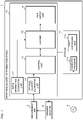
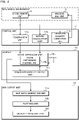
- FIG. 1 is a block diagram illustrating a configuration example of a molding apparatus system according to a first embodiment
- FIG. 2 is a functional block diagram of the molding apparatus system according to the first embodiment.
- the molding apparatus system includes an operation quantity determination device 1, a molding machine 2, and a measurement unit 3.
- the operation quantity determination device 1 further functions as a state display device.
- the molding machine 2 is, for example, an injection molding machine, a hollow molding machine, a film forming machine, an extruder, a twinscrew extruder, a spinning extruder, a granulator, a magnesium injection molding machine, etc.
- the injection molding machine includes an injection device and a mold clamping device disposed in front of the injection device.
- the injection device includes a heating cylinder, a screw that may be driven in a rotational direction and an axial direction in the heating cylinder, a rotary motor that drives the screw in the rotational direction, a motor that drives the screw in the axial direction, etc.
- the mold clamping device includes a toggle mechanism that opens and closes a mold and tightens the mold so that the mold does not open when a molten resin injected from the injection device fills the mold, and a motor that drives the toggle mechanism.
- An operation quantity for determining a molding condition such as a resin temperature in the mold, a nozzle temperature, a cylinder temperature, a hopper temperature, a mold clamping force, an injection speed, injection acceleration, an injection peak pressure, an injection stroke, a cylinder tip resin pressure, a reverse protection ring seated state, a switching pressure of holding pressure, a switching speed of holding pressure, a switching position of holding pressure, a holding pressure completion position, a cushion position, a weighing back pressure, weighing torque, a weighing completion position, a screw retreat speed, a cycle time, a mold closing time, an injection time, a pressure holding time, a weighing time, a mold opening time, etc. is set in the molding machine 2, and the molding machine 2 is operated according to the operation quantity.
- An optimum operation quantity differs depending on the environment of the molding machine 2 and the molded product.
- the measurement unit 3 is a device that measures a physical quantity related to molding by the molding machine 2 when the molding is executed.
- the measurement unit 3 outputs physical quantity data obtained by a measurement process to the operation quantity determination device 1. Examples of the physical quantity include temperature, position, speed, acceleration, current, voltage, pressure, time, image data, torque, force, strain, power consumption, etc.
- information measured by the measurement unit 3 includes molded product information, a molding condition (measured value), a peripheral device set value (measured value), atmosphere information, etc.
- the peripheral device is a device included in a system linked with the molding machine 2, and includes the mold clamping device or the mold.
- the peripheral device is a molded product take-out device (robot), an insert product insertion device, a nesting insertion device, a foil feeder for in-mold molding, a hoop feeder for hoop molding, a gas injection device for gas assist molding, a gas injection device or a long fiber injection device for foam molding using supercritical fluid, an LIM molding material mixing device, a molded product deburring device, a runner cutting device, a molded product weighing scale, a molded product strength tester, a molded product optical inspection device, a molded product photographing device, an image processing device, a molded product transporting robot, etc.
- robot molded product take-out device
- the molded product information includes information such as a camera image obtained by photographing the molded product, the deformation amount of the molded product obtained by a laser displacement sensor, chromaticity of the molded product obtained by an optical measuring instrument, an optical measured value such as luminance, a weight of the molded product measured by a weighing scale, and the strength of the molded product measured by a strength measuring instrument.
- the molded product information expresses whether or not the molded product is normal, the defect type, and the defect degree, and is used for calculating a reward.
- the molding condition includes information such as a resin temperature in the mold, a nozzle temperature, a cylinder temperature, a hopper temperature, a mold clamping force, an injection speed, injection acceleration, an injection peak pressure, an injection stroke, a cylinder tip resin pressure, a reverse protection ring seated state, a switching pressure of holding pressure, a switching speed of holding pressure, a holding pressure switching position, a completion position of holding pressure, a cushion position, a weighing back pressure, weighing torque, a weighing completion position, a screw retreat speed, a cycle time, a mold closing time, an injection time, a pressure holding time, a weighing time, or a mold opening time measured and obtained using a thermometer, a pressure gauge, a speed measuring instrument, an acceleration measuring instrument, a position sensor, a timer, a weighing scale, etc.
- the peripheral device set value includes information such as a mold temperature set as a fixed value, a mold temperature set as a variable value, and the pellet supply amount measured and obtained using a thermometer, a weighing instrument, etc.
- the atmosphere information includes information such as an atmosphere temperature, atmosphere humidity, and information related to convection (Reynolds number, etc.) obtained using a thermometer, a hygrometer, a flow meter, etc.
- the measurement unit 3 may measure the mold opening amount, the backflow amount, the tie bar deformation amount, and a heater heating rate.
- the operation quantity determination device 1 is a computer and includes a processor 10, a storage 11, an input/output interface (not illustrated), etc. as hardware configurations.
- the processor 10 includes an arithmetic circuit such as a CPU (Central Processing Unit), a multicore CPU, a GPU (Graphics Processing Unit), a GPGPU (General-purpose computing on graphics processing units), a TPU (Tensor Processing Unit), an ASIC (Application Specific Integrated Circuit), an FPGA (Field-Programmable Gate Array), or an NPU (Neural Processing Unit), an internal storage device such as a ROM (Read Only Memory) or a RAM (Random Access Memory), an I/O terminal, etc.
- arithmetic circuit such as a CPU (Central Processing Unit), a multicore CPU, a GPU (Graphics Processing Unit), a GPGPU (General-purpose computing on graphics processing units), a TPU (Tensor Processing Unit), an ASIC (Application Specific Integrated Circuit), an FPGA (Field-Pro
- the processor 10 functions as an initial information acquisition unit 12, a physical quantity acquisition unit 13, a control unit 14, a learner 15, and a map output unit 16 by executing a computer program 11a stored in the storage 11 described later.
- Each functional unit of the operation quantity determination device 1 may be realized by software, or some or all functional units thereof may be realized by hardware.
- the operation quantity determination device 1 may be a server device connected to a network (not illustrated).
- the storage 11 is a nonvolatile memory such as a hard disk, an EEPROM (Electrically Erasable Programmable ROM), or a flash memory.
- the storage 11 stores the computer program 11a for causing the computer to execute an operation quantity determination method according to the first embodiment. Further, the storage 11 stores a state expression map 11b, which will be described later, generated by the learner 15.
- the computer program 11a according to the present embodiment may be recorded on a recording medium 4 so as to be readable by the computer.
- the storage 11 stores the computer program 11a read from the recording medium 4 by a reading device (not illustrated).
- the recording medium 4 is a semiconductor memory such as a flash memory.
- the recording medium 4 may be an optical disc such as a CD (Compact Disc)-ROM, a DVD (Digital Versatile Disc)-ROM, or a BD (Blu-ray (registered trademark) Disc).
- the recording medium 4 may be a flexible disk, a magnetic disk such as a hard disk, a magnetic optical disk, etc.
- the computer program 11a according to the present embodiment may be downloaded from an external server (not illustrated) connected to a communication network (not illustrated) and stored in the storage 11.
- the initial information acquisition unit 12 acquires initial information of the molding machine 2 or the product to be molded, which is a premise for determining the operation quantity of the molding machine 2.
- the initial information includes, for example, molding machine information, mold information, resin information, etc.
- the initial information acquisition unit 12 outputs the acquired initial information to the learner 15.
- the molding machine information includes information indicating a model of the molding machine 2, and types or characteristics of a mold clamping unit, an injection unit, a cylinder, a screw, and a nozzle.
- the mold information includes information such as an outer shape of the molded product, the weight of the molded product, the number of samples, the flow length, the thickness of the molded product, the resin pressure, a resin temperature, etc.
- the resin information includes information such as a type, a grade, a manufacturer, the viscosity, crystallinity, the vitrification temperature, a melting point, a composite material, etc.
- the physical quantity acquisition unit 13 acquires physical quantity data measured by the measurement unit 3 and output when molding by the molding machine 2 is executed.
- the physical quantity acquisition unit 13 outputs the acquired physical quantity data to the control unit 14.
- control unit 14 has an observation unit 14a, a reward calculation unit 14b, and an operation quantity correction unit 14c.
- the physical quantity data output from the measurement unit 3 is input to the observation unit 14a, the reward calculation unit 14b, and the operation quantity correction unit 14c.
- the observation unit 14a observes the state of the molding machine 2 by analyzing the physical quantity data, and outputs observation data obtained by observation to a state expression unit 15a of the learner 15. Since the physical quantity data has a large amount of information, the observation unit 14a may generate observation data obtained by compressing information of the physical quantity data.
- the observation data is information indicating an operation state of the molding machine 2, a state of the molded product, etc.
- the observation unit 14a calculates observation data indicating a feature quantity indicating an appearance characteristic of the molded product, the dimensions, area, and volume of the molded product, an optical axis deviation amount of an optical component (molded product), etc. based on a camera image and a measured value of the laser displacement sensor. Further, the observation unit 14a may execute preprocessing on time-series waveform data of the injection speed, injection pressure, holding pressure, etc. and extract the feature quantity of the time-series waveform data as observation data. Time-series data of a time-series waveform and image data representing the time-series waveform may be used as the observation data.
- the reward calculation unit 14b calculates reward data, which is a criterion for suitability of the operation quantity in a current state of the molding machine 2, based on the physical quantity data, and outputs the calculated and obtained reward data to the state expression unit 15a of the learner 15.
- the reward calculation unit 14b analyzes a camera image and physical quantity data such as measured values of the laser displacement sensor and the weighing scale, thereby calculating a molding result indicating whether or not the molded product is normal, a defect degree, a defect type, etc.
- the defect type include warp/deformation, weld line, burr, short, sink mark, void, poor gloss, color unevenness, black spot/contamination, discoloration, flow mark, silver, jetting, reddish brown, etc.
- the defect degree is a degree of defect, an incidence of defect, etc.
- the reward calculation unit 14b calculates reward data indicating suitability of the environment of the molding machine 2 and the operation quantity set in the molding machine 2 based on whether the molded product is normal or not and the defect degree.
- the reward data is, for example, numerical data in which a state where the molded product is normal is 1 and a state where the molded product is defective is less than 1.
- the reward data may be the vector quantity representing the state of the molded product for each defect type.
- the reward data may be the vector quantity in which a state where there is no defect of the defect type is 1 and a state where there is a defect related to the defect type is less than 1 for each defect type.
- a molding result input by an operator may be received by an operation panel having a button, a touch panel, etc.
- the operation quantity correction unit 14c corrects the operation quantity output from the learner 15 as necessary, and outputs the corrected operation quantity to the molding machine 2. For example, when the operation quantity is provided with an upper limit, a lower limit, etc., the operation quantity may be corrected so that a value related to a molding condition does not exceed the upper limit or the lower limit.
- the operation quantity correction unit 14c When correction is unnecessary, the operation quantity correction unit 14c outputs the operation quantity output from the learner 15 to the molding machine 2 without change.
- the learner 15 learns the state expression map 11b (environmental model) expressing the state of the molding machine 2, and performs model-based reinforcement learning for determining the operation quantity using the state expression map 11b. As illustrated in FIG. 2 , the learner 15 has the state expression unit 15a, a state expression learning unit 15b, and an operation quantity output unit 15c.
- the storage 11 stores the learned state expression map 11b.
- the molding apparatus system has a learning phase for learning the state expression map 11b and an operation phase for optimizing the operation quantity using the state expression map 11b and performing molding.
- the molding apparatus system may receive switching between the learning phase and the operation phase on an operation panel (not illustrated).
- FIG. 3 is a block diagram illustrating a function of the state expression unit 15a and input/output data.
- initial information output from the initial information acquisition unit 12 observation data output from the observation unit 14a, reward data output from the reward calculation unit 14b, and the operation quantity output from the operation quantity output unit 15c are input to the state expression unit 15a.
- the state expression unit 15a includes the state expression learning unit 15b, and the state expression learning unit 15b learns the state expression map 11b based on the input initial information, observation data, operation quantity, and reward data.
- the state expression map 11b is a model that outputs a reward g for setting the operation quantity (action a) in a state s and a state transition probability (certainty) Pt to a next state s' when any initial information and observation data (state s) and the operation quantity (action a) are input.
- the reward g may be information indicating whether or not a molded product obtained when a certain operation quantity (action a) is set in the state s is normal. It is desirable that the state expression map 11b expresses the state of the molding machine 2 with data having a lower dimension than that of the observation data.
- the state expression map 11b may be prepared for each type of initial information.
- the state expression learning unit 15b creates or updates the state expression map 11b based on experience data (state s, action a, next state s', reward g) which is learning data or history data. For example, the state expression learning unit 15b may calculate a state transition probability Pt corresponding to a value obtained by dividing the number of visits n to (state s, action a, next state s') by the number of visits ⁇ n to (state s, action a, any next state s' ⁇ S) using the maximum likelihood estimation method, Bayesian estimation, etc.
- the state expression unit 15a may calculate a reward g (information indicating the quality of the molded product) corresponding to a value obtained by dividing a reward sum G in (state s, action a) by the number of visits ⁇ n to (state s, action a, any next state s') using the maximum likelihood estimation method, Bayesian estimation, etc.
- the state expression map 11b may be configured by using a trained model using a neural network.
- the neural network has a known configuration having an input layer, one or more hidden layers and an output layer.
- the state expression learning unit 15b may train the neural network so that when learning data (state s, action a) is input to the neural network, (next state s', reward g), that is, (state transition probability Pt to next state s', reward g) is output from the neural network.
- the state and state expression map may be approximated using a parameter having a smaller degree of freedom than that of the state.
- initial information, observation data, and the operation quantity output from the operation quantity output unit 15c are input to the state expression unit 15a.
- the state expression unit 15a inputs initial information indicating a current state, observation data, and the operation quantity to the state expression map 11b, obtains state expression data indicating the state transition probability Pt to the next state s' from the current state and the reward g, and outputs the state expression data to the operation quantity output unit 15c.
- state expression unit 15a outputs the state expression map 11b together with the initial information and the observation data to the map output unit 16 in the learning phase and the operation phase.
- the operation quantity output unit 15c determines the operation quantity that maximizes a predetermined objective function based on the state expression data output from the state expression unit 15a, and outputs the determined operation quantity to the operation quantity correction unit 14c and the state expression unit 15a. For example, the operation quantity output unit 15c determines the operation quantity using a known method such as a dynamic programming method such as a value iterative method, or a linear programming method.
- FIG. 4 is a block diagram illustrating a function of the operation quantity output unit 15c and input/output data.
- the operation quantity output unit 15c includes a switching unit 15d, a first evaluation unit 15e, a second evaluation unit 15f, and an operation quantity determination unit 15g.
- the switching unit 15d outputs the state expression data to the first evaluation unit 15e in the operation phase, and outputs the state expression data to the second evaluation unit 15f in the learning phase.
- the first evaluation unit 15e has a first objective function for adjusting the operation quantity so that a normal molded product may be obtained. By inputting state expression data and the operation quantity to the first objective function, the first evaluation unit 15e calculates an evaluation value which is an expected return (discount cumulative reward). The expected return is an expected value of the sum of rewards that will be obtained in the future.
- the second evaluation unit 15f has a second objective function for adjusting the operation quantity so that the state of the molded product changes in order to explore for the state expression map 11b.
- the second evaluation unit 15f calculates an evaluation value that increases as a molding result for the state and operation quantity of the molding machine 2 is more unknown, that is, as the number of trials decreases.
- the second evaluation unit 15f may calculate the evaluation value using a exploration method such as the so-called ⁇ -greedy method or UCB1.
- the operation quantity determination unit 15g determines the operation quantity that maximizes the evaluation value calculated by the first evaluation unit 15e in the operation phase, and determines the operation quantity that maximizes the evaluation value calculated by the second evaluation unit 15f in the learning phase.
- the operation quantity output unit 15c outputs the operation quantity determined by the operation quantity determination unit 15g to the state expression unit 15a and the operation quantity correction unit 14c.
- the operation quantity determination unit 15g may determine the operation quantity so that the change amount of the operation quantity per step in the learning phase is larger than the change amount of the operation quantity per step in the operation phase. Further, the operation quantity determination device 1 may be configured to receive the setting of the change amount of the operation quantity per step from an operator on an operation panel (not illustrated). When updating the state expression map 11b, the operation quantity determination unit 15g changes the operation quantity according to the received change amount, explores for the state expression map 11b, and updates the state expression map 11b. When models of the mold, the molding machine 2, and the peripheral device, and physical properties of the resin change significantly, it is advisable to set a large change amount of the operation quantity in the learning phase.
- the map output unit 16 includes a map image generation unit 16a, a plotting unit 16b, and a display processing unit 16c.
- the map image generation unit 16a generates a map image that visualizes the state expression map 11b (see FIGS. 5 and 6 ).
- the map image generation unit 16a may generate a function f(X, Y) based on the state expression map 11b.
- (X, Y) denotes representative values obtained by approximating a state (initial information and observation data) and operation quantity of the molding machine 2 in two dimensions. That is, the representative values (X, Y) are information indicating a molding condition, environment, etc. set in the molding machine 2.
- the function f is a function that returns a value indicating whether a molded product obtained when the operation quantity in a certain state is set in the molding machine 2 is normal or defective.
- the value indicating whether or not the molded product is normal is, for example, a value corresponding to reward data output when the state and the operation quantity are input to the state expression map 11b.
- the function f(X, Y) may be visualized, for example, on a contour map.
- the plotting unit 16b executes a process of plotting a state (X1, Y1) when molding is actually performed on the map image (see FIGS. 5 and 6 ). Further, the plotting unit 16b executes a process of distinguishably displaying whether or not the reward obtained when the molding is actually performed, that is, the molded product is normal in different plotted images (see FIG. 7 ). Further, the plotting unit 16b executes a process of plotting a plurality of states (X1, Y1), (X2, Y2), ...
- the display processing unit 16c executes a process of displaying the map image, a map image plotting a state when actual molding is performed, etc. on a display unit (not illustrated).
- FIG. 5 is a schematic diagram illustrating an example of a map image.
- a horizontal axis and a vertical axis indicate the above-mentioned representative values (X, Y).
- a thick line indicates a boundary between a molding condition in which a normal molded product is obtained and a molding condition in which a defective molded product is obtained.
- the state (initial information and observation data) and the operation quantity are simply referred to as molding conditions.
- a line segment indicating the boundary between the molding condition in which the normal molded product is obtained and the molding condition in which the defective molded product is obtained is simply referred to as a boundary line.
- the map image generation unit 16a may color-code and display a molding condition in which a normal molded product is obtained when a value of the function f is equal to or more than a predetermined threshold value, and a molding condition in which a defective product is obtained when a value of the function f is less than the predetermined threshold value in two colors.
- the color coding by two colors is an example, and any other known method may be used as long as a molding condition in which a normal molded product is obtained and a molding condition in which a defective molded product is obtained are displayed in different modes.
- a black circle indicates a molding condition when the molding is actually performed.
- FIG. 6 is a schematic diagram illustrating another example of a map image. As in FIG. 5 , a horizontal axis and a vertical axis indicate the representative values (X, Y). In FIG. 6 , the normality, the defect, and the degree of the defect of the molded product are displayed in a contour diagram. Specifically, the map image generation unit 16a generates a contour diagram based on the reward g.
- FIG. 7 is a schematic diagram illustrating another example of a map image. As in FIG. 5 , a horizontal axis and a vertical axis indicate the representative values (X, Y). In FIG. 7 , an upper right portion (normal region) indicates a molding condition in which a normal molded product is obtained, and a lower left portion (defective region) indicates a molding condition in which a normal molded product is not obtained.
- Plotted circle marks and X-marks indicate molding conditions when molding was actually performed a plurality of times in the past at positions on the map image, and indicate whether or not molded products are normal as plotted images.
- a circle mark indicates that a normal molded product is obtained, and a plotted X-mark indicates that a normal molded product is not obtained.
- the plotted circle mark and the plotted X-mark are examples of a plotted image indicating whether or not the molded product is normal.
- Other graphic images and character images may be used as long as it is possible to indicate whether or not the molded product is normal or the degree of defect of the molded product.
- a state of the molded product may be represented by color coding.
- FIG. 8 is a schematic diagram illustrating another example of a map image.
- a horizontal axis and a vertical axis indicate the representative values (X, Y).
- Plotted circle marks indicate molding conditions when molding was actually performed a plurality of times in the past.
- the plotting unit 16b superimposes and displays a locus of change in molding condition, in other words, a history of change of a center of gravity of a molding condition group, as an arrow image on the map image. More specifically, it is preferable to calculate a time average speed of the center of gravity on the map image for plotting actual molding and superimpose and display an arrow image indicating the average speed on the map image.
- FIG. 9 is a schematic diagram illustrating another example of a map image.
- the map image generation unit 16a may display a history of change in molding condition in a learning process of the state expression map 11b and a change in boundary line on the map image.
- the learner 15 When learning the state expression map 11b, the learner 15 exploratively changes the molding condition in order to explore for an environmental model.
- the plotting unit 16b superimposes and displays a molding condition in the learning process of the state expression map 11b on the map image. In addition, an arrow image indicating a change in molding condition is displayed.
- the map image generation unit 16a when a position of the boundary line changes in the learning process, the map image generation unit 16a superimposes the boundary line before learning and the boundary line after learning on the map image. Further, the map image generation unit 16a displays an arrow image indicating a changing direction of the boundary line on the map image.
- FIG. 10 is a schematic diagram illustrating another example of a map image.
- a thick and solid line indicates a boundary line in the map image.
- a broken line indicates a confidence interval of the boundary line.
- the confidence interval may be displayed on the state expression map 11b illustrated in FIGS. 5 to 9 above.
- FIGS. 5 to 10 an example of displaying a state where a normal molded product is obtained and a state where a defective product is obtained has been described. However, it is possible to display a state where a defective product is obtained so that a defect type of the defective product is distinguishable.
- reward data is set as a vector quantity representing a state of a molded product for each defect type
- the state expression map 11b is configured to output reward data which is a vector quantity when a state and the operation quantity are input.
- the function f(X, Y) may be a function that returns a value (f1, f2, f3, ... fN) indicating a state of a molded product obtained when the operation quantity in a certain state is set in the molding machine 2 for each defect type.
- fi i is a natural number of 1 to N indicating a defect type
- the map image generation unit 16a generates a map image on which a molding condition indicated by the representative values (X, Y) is displayed so that a state where a normal molded product is obtained and a plurality of states in which defects of respective defect types appear are distinguishable based on the values of f1, f2, ... fN.
- the operator may visually recognize from the map image what sort of defect type is likely to appear.
- FIG. 11 is a sequence diagram illustrating an operation of the operation quantity determination device 1 in the learning phase.
- a part surrounded by a dotted line on the left side indicates an environment in the real world, that is, an operation of the molding machine 2 and a measurement operation by the measurement unit 3.
- a part surrounded by a broken line in the center indicates a processing operation of the control unit 14, and a part surrounded by a broken line on the right side indicates a processing operation of the learner 15.
- the measurement unit 3 measures a physical quantity related to the molding machine 2 and the molded product, and outputs physical quantity data obtained by measurement to the observation unit 14a (step S11).
- the observation unit 14a acquires the physical quantity data output from the measurement unit 3, generates observation data based on the acquired physical quantity data, and outputs the generated observation data to the state expression unit 15a (step S12).
- the state expression unit 15a acquires the observation data output from the observation unit 14a, applies the observation data, an initial state, etc. to the state expression map 11b to create state expression data, and outputs the created state expression data to the operation quantity output unit 15c (step S13).
- the operation quantity output unit 15c determines the operation quantity of the molding machine 2 based on the state expression data output from the state expression unit 15a, and outputs the determined operation quantity to the state expression unit 15a and the operation quantity correction unit 14c (step S14 and step S15). For example, the operation quantity output unit 15c determines the operation quantity that maximizes an evaluation value obtained from the second objective function as described above.
- the measurement unit 3 outputs the physical quantity data obtained by measurement to the operation quantity correction unit 14c (step S16).
- the operation quantity correction unit 14c corrects the operation quantity as necessary based on the physical quantity data, and outputs the corrected operation quantity to the molding machine 2 (step S17).
- the molding machine 2 sets the operation quantity and performs a molding process according to the operation quantity.
- the physical quantity related to the operation of the molding machine 2 and the molded product are input to the measurement unit 3 (step S18).
- the molding process may be repeated a plurality of times.
- the measurement unit 3 measures the physical quantity related to the molding machine 2 and the molded product when the molding machine 2 executes molding, and outputs physical quantity data obtained by measurement to the observation unit 14a and the reward calculation unit 14b (step S19 and step S20).
- the observation unit 14a acquires the physical quantity data output from the measurement unit 3, generates observation data based on the acquired physical quantity data, and outputs the generated observation data to the state expression unit 15a (step S21).
- the reward calculation unit 14b calculates reward data determined according to whether or not the molded product is normal and a degree of defect based on the physical quantity data measured by the measurement unit 3, and outputs the calculated reward data to the state expression unit 15a (step S22).
- the state expression learning unit 15b of the state expression unit 15a updates a state expression model based on observation data output from the observation unit 14a, reward data output from the reward calculation unit 14b, the operation quantity output from the operation quantity output unit 15c, and initial information (step S23).
- the state expression learning unit 15b may update the state expression model using, for example, the maximum likelihood estimation method, Bayesian estimation, etc.
- FIG. 12 is a sequence diagram illustrating an operation of the operation quantity determination device 1 in the operation phase.
- the measurement unit 3 measures the physical quantity related to the molding machine 2 and the molded product when the molding machine 2 executes molding, and outputs physical quantity data obtained by measurement to the observation unit 14a (step S31).
- the observation unit 14a acquires the physical quantity data output from the measurement unit 3, generates observation data based on the acquired physical quantity data, and outputs the generated observation data to the state expression unit 15a (step S32).
- the state expression unit 15a acquires the observation data output from the observation unit 14a, applies the observation data and an initial state etc. to the state expression map 11b to create state expression data, and outputs the created state expression data to the operation quantity output unit 15c (step S33).
- the operation quantity output unit 15c determines the operation quantity of the molding machine 2 based on the state expression data output from the state expression unit 15a, and outputs the determined operation quantity to the state expression unit 15a and the operation quantity correction unit 14c (step S34 and step S35). For example, the operation quantity output unit 15c determines the operation quantity that maximizes an expected return (discount cumulative reward) obtained from the first objective function as described above.
- the measurement unit 3 outputs the physical quantity data obtained by measurement to the operation quantity correction unit 14c (step S36).
- the operation quantity correction unit 14c corrects the operation quantity as necessary based on the physical quantity data, and outputs the corrected operation quantity to the molding machine 2 (step S37).
- the molding machine 2 sets the operation quantity and performs a molding process according to the operation quantity.
- a physical quantity related to the operation of the molding machine 2 and the molded product is input to the measurement unit 3 (step S38).
- the operator may appropriately switch an operation mode from the operation phase to the learning phase and update the state expression map 11b.
- the operation quantity determination device 1 switched from the operation phase to the learning phase may update the state expression map 11b by executing the process illustrated in FIG. 11 .
- the operation quantity output unit 15c explores for a region in which the state expression map 11b needs to be updated by outputting the operation quantity related to the vicinity of the boundary. Further, the operation quantity output unit 15c may start exploring for the state expression map 11b by using the operation quantity corresponding to the vicinity of the boundary line on the map image. Then, the state expression learning unit 15b updates the state expression map 11b based on experience data or history data obtained in a process of the exploration.
- an operation quantity calculation device According to the molding apparatus system, an operation quantity calculation device, an operation quantity calculation method, and the computer program 11a according to the first embodiment, it is possible to perform additional learning excellent in robustness against environmental changes and for adapting to a new environment in a short time.
- the operation quantity determination device 1 may generate the state expression map 11b in consideration of initial information related to the molding machine 2 or the molded product.
- the state expression map 11b may be updated to cope with the change in the environment.
- the state expression map 11b may be efficiently updated by outputting the operation quantity that changes the molding result in the learning phase.
- the state expression map 11b when the state expression map 11b is explored in the learning phase, the state expression map 11b may be efficiently updated by increasing a fluctuation range of the operation quantity.
- the policy for determining the operation quantity may be changed between the learning phase and the operation phase.
- the state expression map 11b may be efficiently updated, and in the operation phase, the operation quantity may be efficiently adjusted to a state where the molded product is obtained.
- the map output unit 16 may visualize and display the state expression map 11b as a map image.
- the map image may distinguishably display a molding condition in which a normal molded product is obtained and a molding condition in which a defective molded product is obtained.
- map output unit 16 may plot and display a current molding condition actually performed on the state expression map 11b.
- the map output unit 16 may display whether a molded product actually obtained under a molding condition is normal or defective as different plotted image. The operator may intuitively recognize whether or not a current molding condition is in a state where a normal molded product is obtained, and a degree at which the current molding condition is away from a state where a normal molded product is obtained.
- the map output unit 16 may display a boundary line between a state where a normal molded product is obtained and a state where a molded product is defective, and display a change of the boundary line due to learning of the state expression map 11b on a map image. The operator may intuitively recognize a learning status of the state expression map 11b.
- a molding machine according to a second embodiment is different from that of the first embodiment in that an operation quantity determination device is provided in the molding machine. Therefore, the difference will be mainly described below. Since other configurations, actions, and effects are similar to those in the first embodiment, the corresponding parts are designated by similar reference symbols and detailed description thereof will be omitted.
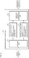
- FIG. 13 is a block diagram illustrating a molding machine 202 according to the second embodiment.
- the molding machine 202 according to the second embodiment includes an injection device 221, a mold clamping device 222 disposed in front of the injection device 221, and a control device 220 for controlling the operation of the molding machine 202.
- the control device 220 includes the operation quantity determination device 1 described in the first embodiment.
- the molding machine 202 may learn the state expression map 11b by itself, determine the operation quantity for reducing a defect degree, and operate based on the determined operation quantity.
Landscapes
- Engineering & Computer Science (AREA)
- Artificial Intelligence (AREA)
- Physics & Mathematics (AREA)
- Mechanical Engineering (AREA)
- Manufacturing & Machinery (AREA)
- Health & Medical Sciences (AREA)
- General Physics & Mathematics (AREA)
- Evolutionary Computation (AREA)
- Software Systems (AREA)
- Theoretical Computer Science (AREA)
- Automation & Control Theory (AREA)
- Medical Informatics (AREA)
- Computer Vision & Pattern Recognition (AREA)
- Biophysics (AREA)
- General Engineering & Computer Science (AREA)
- Mathematical Physics (AREA)
- Computing Systems (AREA)
- Molecular Biology (AREA)
- General Health & Medical Sciences (AREA)
- Data Mining & Analysis (AREA)
- Computational Linguistics (AREA)
- Biomedical Technology (AREA)
- Life Sciences & Earth Sciences (AREA)
- Injection Moulding Of Plastics Or The Like (AREA)
Abstract
Description
- The present invention relates to an operation quantity determination device, a molding apparatus system, a molding machine, a computer program, an operation quantity determination method, and a state display device.
-
Patent Document 1 discloses an injection molding apparatus system and a machine learning device for determining an optimum operating condition having low power consumption by a reinforcement learning device and adjusting the operating condition. -
Patent Document 2 discloses an abnormality diagnosis apparatus for diagnosing an abnormality in an injection molding machine by machine learning. -
- [Patent Document 1]
Japanese Patent No. 6346128 - [Patent Document 2]
Japanese Patent No. 6294268 - However, the injection molding apparatus system according to
Patent Document 1 is a system in which the operation quantity of a molding machine is determined by model-free reinforcement learning, and when the environment changes, a policy for determining the operation quantity may not be applicable. In this case, it is necessary to relearn the policy from scratch. Learning the policy requires a huge amount of training data or training work, and has a problem of lacking versatility. - The apparatus of
Patent Document 2 may perform an abnormality diagnosis of injection molding. However, the apparatus cannot determine an optimum operation quantity of a molding machine. - An object of the invention is to provide an operation quantity determination device, a molding apparatus system, a molding machine, a computer program, an operation quantity determination method, and a state display device excellent in robustness against environmental changes and capable of performing additional learning for adapting to a new environment in a short time.
- An operation quantity determination device of the present embodiment is the operation quantity determination device for determining an operation quantity related to a molding machine, the device comprising: an observation unit configured to acquire observation data obtained by observing a physical quantity related to molding by the molding machine when the molding is executed; a state expression unit configured to generate a state expression map expressing a state of the molding machine based on the observation data acquired by the observation unit; and an operation quantity output unit configured to output the operation quantity based on the state expression map generated by the state expression unit.
- A molding apparatus system of the present embodiment is the molding apparatus system, comprising: the above operation quantity determination device; and a molding machine.
- A molding machine of the present embodiment is the molding machine, comprising the above operation quantity determination device, wherein the molding machine operates based on the operation quantity determined by the operation quantity determination device.
- A computer program of the present embodiment is the computer program for causing a computer to determine an operation quantity related to a molding machine, the computer program causing the computer to execute processes of: acquiring observation data obtained by observing a physical quantity related to molding by the molding machine when the molding is executed; generating a state expression map expressing a state of the molding machine based on the acquired observation data; and outputting the operation quantity based on the generated state expression map.
- A operation quantity determination method of the present embodiment is the operation quantity determination method for determining an operation quantity related to a molding machine, the method comprising: acquiring observation data obtained by observing a physical quantity related to molding by the molding machine when the molding is executed; generating a state expression map expressing a state of the molding machine based on the acquired observation data; and outputting the operation quantity based on the generated state expression map.
- A state display device of the present embodiment is the state display device, comprising: an observation unit configured to acquire observation data obtained by observing a physical quantity related to molding by the molding machine when the molding is executed; and a display processing unit configured to display a map image related to a state expression map expressing a state of the molding machine based on the observation data acquired by the observation unit and an actual molding result by the molding machine so that the map image and the actual molding result are allowed to be compared with each other.
- According to the above description, robustness against environmental changes is excellent, and additional learning for adapting to a new environment may be performed in a short time.
-
-
FIG. 1 is a block diagram illustrating a configuration example of a molding apparatus system according to a first embodiment. -
FIG. 2 is a functional block diagram of the molding apparatus system according to the first embodiment. -
FIG. 3 is a block diagram illustrating a function of a state expression unit and input/output data. -
FIG. 4 is a block diagram illustrating a function of an operation quantity output unit and input/output data. -
FIG. 5 is a schematic diagram illustrating an example of a map image. -
FIG. 6 is a schematic diagram illustrating another example of a map image. -
FIG. 7 is a schematic diagram illustrating another example of a map image. -
FIG. 8 is a schematic diagram illustrating another example of a map image. -
FIG. 9 is a schematic diagram illustrating another example of a map image. -
FIG. 10 is a schematic diagram illustrating another example of a map image. -
FIG. 11 is a sequence diagram illustrating an operation of an operation quantity determination device in a learning phase. -
FIG. 12 is a sequence diagram illustrating an operation of the operation quantity determination device in an operation phase. -
FIG. 13 is a block diagram illustrating a molding machine according to a second embodiment. - Hereinafter, specific examples of an operation quantity determination device, a molding apparatus system, a molding machine, a computer program, an operation quantity determination method, and a state display device according to embodiments of the invention will be described below with reference to the drawings. At least some of the embodiments described below may be optionally combined. It should be noted that the invention is not limited to these examples, is indicated by the scope of claims, and is intended to include all modifications within the meaning and scope equivalent to the scope of claims.
-
FIG. 1 is a block diagram illustrating a configuration example of a molding apparatus system according to a first embodiment, andFIG. 2 is a functional block diagram of the molding apparatus system according to the first embodiment. - The molding apparatus system according to the first embodiment includes an operation
quantity determination device 1, amolding machine 2, and ameasurement unit 3. The operationquantity determination device 1 further functions as a state display device. - The
molding machine 2 is, for example, an injection molding machine, a hollow molding machine, a film forming machine, an extruder, a twinscrew extruder, a spinning extruder, a granulator, a magnesium injection molding machine, etc. Hereinafter, in the first embodiment, a description will be given on the assumption that themolding machine 2 is the injection molding machine. The injection molding machine includes an injection device and a mold clamping device disposed in front of the injection device. The injection device includes a heating cylinder, a screw that may be driven in a rotational direction and an axial direction in the heating cylinder, a rotary motor that drives the screw in the rotational direction, a motor that drives the screw in the axial direction, etc. The mold clamping device includes a toggle mechanism that opens and closes a mold and tightens the mold so that the mold does not open when a molten resin injected from the injection device fills the mold, and a motor that drives the toggle mechanism. - An operation quantity for determining a molding condition such as a resin temperature in the mold, a nozzle temperature, a cylinder temperature, a hopper temperature, a mold clamping force, an injection speed, injection acceleration, an injection peak pressure, an injection stroke, a cylinder tip resin pressure, a reverse protection ring seated state, a switching pressure of holding pressure, a switching speed of holding pressure, a switching position of holding pressure, a holding pressure completion position, a cushion position, a weighing back pressure, weighing torque, a weighing completion position, a screw retreat speed, a cycle time, a mold closing time, an injection time, a pressure holding time, a weighing time, a mold opening time, etc. is set in the
molding machine 2, and themolding machine 2 is operated according to the operation quantity. An optimum operation quantity differs depending on the environment of themolding machine 2 and the molded product. - The
measurement unit 3 is a device that measures a physical quantity related to molding by themolding machine 2 when the molding is executed. Themeasurement unit 3 outputs physical quantity data obtained by a measurement process to the operationquantity determination device 1. Examples of the physical quantity include temperature, position, speed, acceleration, current, voltage, pressure, time, image data, torque, force, strain, power consumption, etc. - For example, information measured by the
measurement unit 3 includes molded product information, a molding condition (measured value), a peripheral device set value (measured value), atmosphere information, etc. The peripheral device is a device included in a system linked with themolding machine 2, and includes the mold clamping device or the mold. For example, the peripheral device is a molded product take-out device (robot), an insert product insertion device, a nesting insertion device, a foil feeder for in-mold molding, a hoop feeder for hoop molding, a gas injection device for gas assist molding, a gas injection device or a long fiber injection device for foam molding using supercritical fluid, an LIM molding material mixing device, a molded product deburring device, a runner cutting device, a molded product weighing scale, a molded product strength tester, a molded product optical inspection device, a molded product photographing device, an image processing device, a molded product transporting robot, etc. - For example, the molded product information includes information such as a camera image obtained by photographing the molded product, the deformation amount of the molded product obtained by a laser displacement sensor, chromaticity of the molded product obtained by an optical measuring instrument, an optical measured value such as luminance, a weight of the molded product measured by a weighing scale, and the strength of the molded product measured by a strength measuring instrument. The molded product information expresses whether or not the molded product is normal, the defect type, and the defect degree, and is used for calculating a reward.
- The molding condition includes information such as a resin temperature in the mold, a nozzle temperature, a cylinder temperature, a hopper temperature, a mold clamping force, an injection speed, injection acceleration, an injection peak pressure, an injection stroke, a cylinder tip resin pressure, a reverse protection ring seated state, a switching pressure of holding pressure, a switching speed of holding pressure, a holding pressure switching position, a completion position of holding pressure, a cushion position, a weighing back pressure, weighing torque, a weighing completion position, a screw retreat speed, a cycle time, a mold closing time, an injection time, a pressure holding time, a weighing time, or a mold opening time measured and obtained using a thermometer, a pressure gauge, a speed measuring instrument, an acceleration measuring instrument, a position sensor, a timer, a weighing scale, etc.
- The peripheral device set value includes information such as a mold temperature set as a fixed value, a mold temperature set as a variable value, and the pellet supply amount measured and obtained using a thermometer, a weighing instrument, etc.
- The atmosphere information includes information such as an atmosphere temperature, atmosphere humidity, and information related to convection (Reynolds number, etc.) obtained using a thermometer, a hygrometer, a flow meter, etc.
- In addition, the
measurement unit 3 may measure the mold opening amount, the backflow amount, the tie bar deformation amount, and a heater heating rate. - The operation
quantity determination device 1 is a computer and includes aprocessor 10, astorage 11, an input/output interface (not illustrated), etc. as hardware configurations. Theprocessor 10 includes an arithmetic circuit such as a CPU (Central Processing Unit), a multicore CPU, a GPU (Graphics Processing Unit), a GPGPU (General-purpose computing on graphics processing units), a TPU (Tensor Processing Unit), an ASIC (Application Specific Integrated Circuit), an FPGA (Field-Programmable Gate Array), or an NPU (Neural Processing Unit), an internal storage device such as a ROM (Read Only Memory) or a RAM (Random Access Memory), an I/O terminal, etc. Theprocessor 10 functions as an initialinformation acquisition unit 12, a physicalquantity acquisition unit 13, acontrol unit 14, alearner 15, and amap output unit 16 by executing acomputer program 11a stored in thestorage 11 described later. Each functional unit of the operationquantity determination device 1 may be realized by software, or some or all functional units thereof may be realized by hardware. - The operation
quantity determination device 1 may be a server device connected to a network (not illustrated). - The
storage 11 is a nonvolatile memory such as a hard disk, an EEPROM (Electrically Erasable Programmable ROM), or a flash memory. Thestorage 11 stores thecomputer program 11a for causing the computer to execute an operation quantity determination method according to the first embodiment. Further, thestorage 11 stores astate expression map 11b, which will be described later, generated by thelearner 15. - The
computer program 11a according to the present embodiment may be recorded on a recording medium 4 so as to be readable by the computer. Thestorage 11 stores thecomputer program 11a read from the recording medium 4 by a reading device (not illustrated). The recording medium 4 is a semiconductor memory such as a flash memory. Further, the recording medium 4 may be an optical disc such as a CD (Compact Disc)-ROM, a DVD (Digital Versatile Disc)-ROM, or a BD (Blu-ray (registered trademark) Disc). Further, the recording medium 4 may be a flexible disk, a magnetic disk such as a hard disk, a magnetic optical disk, etc. Furthermore, thecomputer program 11a according to the present embodiment may be downloaded from an external server (not illustrated) connected to a communication network (not illustrated) and stored in thestorage 11. - The initial
information acquisition unit 12 acquires initial information of themolding machine 2 or the product to be molded, which is a premise for determining the operation quantity of themolding machine 2. The initial information includes, for example, molding machine information, mold information, resin information, etc. The initialinformation acquisition unit 12 outputs the acquired initial information to thelearner 15. The molding machine information includes information indicating a model of themolding machine 2, and types or characteristics of a mold clamping unit, an injection unit, a cylinder, a screw, and a nozzle. - The mold information includes information such as an outer shape of the molded product, the weight of the molded product, the number of samples, the flow length, the thickness of the molded product, the resin pressure, a resin temperature, etc.
- The resin information includes information such as a type, a grade, a manufacturer, the viscosity, crystallinity, the vitrification temperature, a melting point, a composite material, etc.
- It is difficult to create the
state expression map 11b by rigorously digitizing all the initial information, or to construct thestate expression map 11b for each piece of initial information. Thus, it is desirable to define required initial information in one-hot expression. - The physical
quantity acquisition unit 13 acquires physical quantity data measured by themeasurement unit 3 and output when molding by themolding machine 2 is executed. The physicalquantity acquisition unit 13 outputs the acquired physical quantity data to thecontrol unit 14. - As illustrated in
FIG. 2 , thecontrol unit 14 has anobservation unit 14a, areward calculation unit 14b, and an operationquantity correction unit 14c. The physical quantity data output from themeasurement unit 3 is input to theobservation unit 14a, thereward calculation unit 14b, and the operationquantity correction unit 14c. - The
observation unit 14a observes the state of themolding machine 2 by analyzing the physical quantity data, and outputs observation data obtained by observation to astate expression unit 15a of thelearner 15. Since the physical quantity data has a large amount of information, theobservation unit 14a may generate observation data obtained by compressing information of the physical quantity data. The observation data is information indicating an operation state of themolding machine 2, a state of the molded product, etc. - For example, the
observation unit 14a calculates observation data indicating a feature quantity indicating an appearance characteristic of the molded product, the dimensions, area, and volume of the molded product, an optical axis deviation amount of an optical component (molded product), etc. based on a camera image and a measured value of the laser displacement sensor. Further, theobservation unit 14a may execute preprocessing on time-series waveform data of the injection speed, injection pressure, holding pressure, etc. and extract the feature quantity of the time-series waveform data as observation data. Time-series data of a time-series waveform and image data representing the time-series waveform may be used as the observation data. - The
reward calculation unit 14b calculates reward data, which is a criterion for suitability of the operation quantity in a current state of themolding machine 2, based on the physical quantity data, and outputs the calculated and obtained reward data to thestate expression unit 15a of thelearner 15. - For example, the
reward calculation unit 14b analyzes a camera image and physical quantity data such as measured values of the laser displacement sensor and the weighing scale, thereby calculating a molding result indicating whether or not the molded product is normal, a defect degree, a defect type, etc. Examples of the defect type include warp/deformation, weld line, burr, short, sink mark, void, poor gloss, color unevenness, black spot/contamination, discoloration, flow mark, silver, jetting, reddish brown, etc. The defect degree is a degree of defect, an incidence of defect, etc. Then, thereward calculation unit 14b calculates reward data indicating suitability of the environment of themolding machine 2 and the operation quantity set in themolding machine 2 based on whether the molded product is normal or not and the defect degree. The reward data is, for example, numerical data in which a state where the molded product is normal is 1 and a state where the molded product is defective is less than 1. - The reward data may be the vector quantity representing the state of the molded product for each defect type. For example, the reward data may be the vector quantity in which a state where there is no defect of the defect type is 1 and a state where there is a defect related to the defect type is less than 1 for each defect type.
- Further, even though an example of calculating the molding result by analyzing the physical quantity data has been described, a molding result input by an operator may be received by an operation panel having a button, a touch panel, etc.
- The operation
quantity correction unit 14c corrects the operation quantity output from thelearner 15 as necessary, and outputs the corrected operation quantity to themolding machine 2. For example, when the operation quantity is provided with an upper limit, a lower limit, etc., the operation quantity may be corrected so that a value related to a molding condition does not exceed the upper limit or the lower limit. - When correction is unnecessary, the operation
quantity correction unit 14c outputs the operation quantity output from thelearner 15 to themolding machine 2 without change. - The
learner 15 learns thestate expression map 11b (environmental model) expressing the state of themolding machine 2, and performs model-based reinforcement learning for determining the operation quantity using thestate expression map 11b. As illustrated inFIG. 2 , thelearner 15 has thestate expression unit 15a, a stateexpression learning unit 15b, and an operationquantity output unit 15c. Thestorage 11 stores the learnedstate expression map 11b. - The molding apparatus system according to the first embodiment has a learning phase for learning the
state expression map 11b and an operation phase for optimizing the operation quantity using thestate expression map 11b and performing molding. The molding apparatus system may receive switching between the learning phase and the operation phase on an operation panel (not illustrated). -
FIG. 3 is a block diagram illustrating a function of thestate expression unit 15a and input/output data. - In the case of the learning phase for learning the
state expression map 11b, as illustrated inFIG. 3 , initial information output from the initialinformation acquisition unit 12, observation data output from theobservation unit 14a, reward data output from thereward calculation unit 14b, and the operation quantity output from the operationquantity output unit 15c are input to thestate expression unit 15a. Thestate expression unit 15a includes the stateexpression learning unit 15b, and the stateexpression learning unit 15b learns thestate expression map 11b based on the input initial information, observation data, operation quantity, and reward data. - For example, the
state expression map 11b is a model that outputs a reward g for setting the operation quantity (action a) in a state s and a state transition probability (certainty) Pt to a next state s' when any initial information and observation data (state s) and the operation quantity (action a) are input. The reward g may be information indicating whether or not a molded product obtained when a certain operation quantity (action a) is set in the state s is normal. It is desirable that thestate expression map 11b expresses the state of themolding machine 2 with data having a lower dimension than that of the observation data. - The
state expression map 11b may be prepared for each type of initial information. - The state
expression learning unit 15b creates or updates thestate expression map 11b based on experience data (state s, action a, next state s', reward g) which is learning data or history data. For example, the stateexpression learning unit 15b may calculate a state transition probability Pt corresponding to a value obtained by dividing the number of visits n to (state s, action a, next state s') by the number of visits Σn to (state s, action a, any next state s' ∈ S) using the maximum likelihood estimation method, Bayesian estimation, etc. In addition, thestate expression unit 15a may calculate a reward g (information indicating the quality of the molded product) corresponding to a value obtained by dividing a reward sum G in (state s, action a) by the number of visits Σn to (state s, action a, any next state s') using the maximum likelihood estimation method, Bayesian estimation, etc. - Further, the
state expression map 11b may be configured by using a trained model using a neural network. The neural network has a known configuration having an input layer, one or more hidden layers and an output layer. The stateexpression learning unit 15b may train the neural network so that when learning data (state s, action a) is input to the neural network, (next state s', reward g), that is, (state transition probability Pt to next state s', reward g) is output from the neural network. - When the number of states represented by an initial state and observation data is enormous, the state and state expression map may be approximated using a parameter having a smaller degree of freedom than that of the state.
- In the operation phase in which the
molding machine 2 is operated using the createdstate expression map 11b, initial information, observation data, and the operation quantity output from the operationquantity output unit 15c are input to thestate expression unit 15a. Thestate expression unit 15a inputs initial information indicating a current state, observation data, and the operation quantity to thestate expression map 11b, obtains state expression data indicating the state transition probability Pt to the next state s' from the current state and the reward g, and outputs the state expression data to the operationquantity output unit 15c. - Further, the
state expression unit 15a outputs thestate expression map 11b together with the initial information and the observation data to themap output unit 16 in the learning phase and the operation phase. - The operation
quantity output unit 15c determines the operation quantity that maximizes a predetermined objective function based on the state expression data output from thestate expression unit 15a, and outputs the determined operation quantity to the operationquantity correction unit 14c and thestate expression unit 15a. For example, the operationquantity output unit 15c determines the operation quantity using a known method such as a dynamic programming method such as a value iterative method, or a linear programming method. -
FIG. 4 is a block diagram illustrating a function of the operationquantity output unit 15c and input/output data. The operationquantity output unit 15c includes aswitching unit 15d, afirst evaluation unit 15e, asecond evaluation unit 15f, and an operationquantity determination unit 15g. - The
switching unit 15d outputs the state expression data to thefirst evaluation unit 15e in the operation phase, and outputs the state expression data to thesecond evaluation unit 15f in the learning phase. - The
first evaluation unit 15e has a first objective function for adjusting the operation quantity so that a normal molded product may be obtained. By inputting state expression data and the operation quantity to the first objective function, thefirst evaluation unit 15e calculates an evaluation value which is an expected return (discount cumulative reward). The expected return is an expected value of the sum of rewards that will be obtained in the future. - The
second evaluation unit 15f has a second objective function for adjusting the operation quantity so that the state of the molded product changes in order to explore for thestate expression map 11b. By inputting state expression data and the operation quantity to the second objective function, for example, thesecond evaluation unit 15f calculates an evaluation value that increases as a molding result for the state and operation quantity of themolding machine 2 is more unknown, that is, as the number of trials decreases. Thesecond evaluation unit 15f may calculate the evaluation value using a exploration method such as the so-called ε-greedy method or UCB1. - The operation
quantity determination unit 15g determines the operation quantity that maximizes the evaluation value calculated by thefirst evaluation unit 15e in the operation phase, and determines the operation quantity that maximizes the evaluation value calculated by thesecond evaluation unit 15f in the learning phase. The operationquantity output unit 15c outputs the operation quantity determined by the operationquantity determination unit 15g to thestate expression unit 15a and the operationquantity correction unit 14c. - The operation
quantity determination unit 15g may determine the operation quantity so that the change amount of the operation quantity per step in the learning phase is larger than the change amount of the operation quantity per step in the operation phase. Further, the operationquantity determination device 1 may be configured to receive the setting of the change amount of the operation quantity per step from an operator on an operation panel (not illustrated). When updating thestate expression map 11b, the operationquantity determination unit 15g changes the operation quantity according to the received change amount, explores for thestate expression map 11b, and updates thestate expression map 11b. When models of the mold, themolding machine 2, and the peripheral device, and physical properties of the resin change significantly, it is advisable to set a large change amount of the operation quantity in the learning phase. - The
map output unit 16 includes a mapimage generation unit 16a, a plottingunit 16b, and adisplay processing unit 16c. - The map
image generation unit 16a generates a map image that visualizes thestate expression map 11b (seeFIGS. 5 and6 ). For example, the mapimage generation unit 16a may generate a function f(X, Y) based on thestate expression map 11b. For example, (X, Y) denotes representative values obtained by approximating a state (initial information and observation data) and operation quantity of themolding machine 2 in two dimensions. That is, the representative values (X, Y) are information indicating a molding condition, environment, etc. set in themolding machine 2. The function f is a function that returns a value indicating whether a molded product obtained when the operation quantity in a certain state is set in themolding machine 2 is normal or defective. The value indicating whether or not the molded product is normal is, for example, a value corresponding to reward data output when the state and the operation quantity are input to thestate expression map 11b. The function f(X, Y) may be visualized, for example, on a contour map. - The plotting
unit 16b executes a process of plotting a state (X1, Y1) when molding is actually performed on the map image (seeFIGS. 5 and6 ). Further, the plottingunit 16b executes a process of distinguishably displaying whether or not the reward obtained when the molding is actually performed, that is, the molded product is normal in different plotted images (seeFIG. 7 ). Further, the plottingunit 16b executes a process of plotting a plurality of states (X1, Y1), (X2, Y2), ... on a map image when the actual molding is performed a plurality of times, and displaying an image showing a direction of change in the state, for example, a change in the center of gravity of a plot group on a map image as an arrow image (seeFIG. 8 ). - The
display processing unit 16c executes a process of displaying the map image, a map image plotting a state when actual molding is performed, etc. on a display unit (not illustrated). -
FIG. 5 is a schematic diagram illustrating an example of a map image. In the figure, a horizontal axis and a vertical axis indicate the above-mentioned representative values (X, Y). InFIG. 5 , a thick line indicates a boundary between a molding condition in which a normal molded product is obtained and a molding condition in which a defective molded product is obtained. Hereinafter, the state (initial information and observation data) and the operation quantity are simply referred to as molding conditions. Further, on the map image, a line segment indicating the boundary between the molding condition in which the normal molded product is obtained and the molding condition in which the defective molded product is obtained is simply referred to as a boundary line. - For example, the map
image generation unit 16a may color-code and display a molding condition in which a normal molded product is obtained when a value of the function f is equal to or more than a predetermined threshold value, and a molding condition in which a defective product is obtained when a value of the function f is less than the predetermined threshold value in two colors. The color coding by two colors is an example, and any other known method may be used as long as a molding condition in which a normal molded product is obtained and a molding condition in which a defective molded product is obtained are displayed in different modes. - In
FIG. 5 , a black circle indicates a molding condition when the molding is actually performed. -
FIG. 6 is a schematic diagram illustrating another example of a map image. As inFIG. 5 , a horizontal axis and a vertical axis indicate the representative values (X, Y). InFIG. 6 , the normality, the defect, and the degree of the defect of the molded product are displayed in a contour diagram. Specifically, the mapimage generation unit 16a generates a contour diagram based on the reward g. -
FIG. 7 is a schematic diagram illustrating another example of a map image. As inFIG. 5 , a horizontal axis and a vertical axis indicate the representative values (X, Y). InFIG. 7 , an upper right portion (normal region) indicates a molding condition in which a normal molded product is obtained, and a lower left portion (defective region) indicates a molding condition in which a normal molded product is not obtained. - Plotted circle marks and X-marks indicate molding conditions when molding was actually performed a plurality of times in the past at positions on the map image, and indicate whether or not molded products are normal as plotted images. A circle mark indicates that a normal molded product is obtained, and a plotted X-mark indicates that a normal molded product is not obtained.
- As illustrated in
FIG. 7 , it may be seen that even in a molding condition in which a normal molded product is obtained, molding defect occurs when molding is actually performed. - In
FIG. 7 , the plotted circle mark and the plotted X-mark are examples of a plotted image indicating whether or not the molded product is normal. Other graphic images and character images may be used as long as it is possible to indicate whether or not the molded product is normal or the degree of defect of the molded product. Further, a state of the molded product may be represented by color coding. -
FIG. 8 is a schematic diagram illustrating another example of a map image. As inFIG. 7 , a horizontal axis and a vertical axis indicate the representative values (X, Y). Plotted circle marks indicate molding conditions when molding was actually performed a plurality of times in the past. Further, the plottingunit 16b superimposes and displays a locus of change in molding condition, in other words, a history of change of a center of gravity of a molding condition group, as an arrow image on the map image. More specifically, it is preferable to calculate a time average speed of the center of gravity on the map image for plotting actual molding and superimpose and display an arrow image indicating the average speed on the map image. -
FIG. 9 is a schematic diagram illustrating another example of a map image. The mapimage generation unit 16a may display a history of change in molding condition in a learning process of thestate expression map 11b and a change in boundary line on the map image. - When learning the
state expression map 11b, thelearner 15 exploratively changes the molding condition in order to explore for an environmental model. The plottingunit 16b superimposes and displays a molding condition in the learning process of thestate expression map 11b on the map image. In addition, an arrow image indicating a change in molding condition is displayed. - Further, when a position of the boundary line changes in the learning process, the map
image generation unit 16a superimposes the boundary line before learning and the boundary line after learning on the map image. Further, the mapimage generation unit 16a displays an arrow image indicating a changing direction of the boundary line on the map image. -
FIG. 10 is a schematic diagram illustrating another example of a map image. A thick and solid line indicates a boundary line in the map image. A broken line indicates a confidence interval of the boundary line. - It is obvious that the confidence interval may be displayed on the
state expression map 11b illustrated inFIGS. 5 to 9 above. - In
FIGS. 5 to 10 , an example of displaying a state where a normal molded product is obtained and a state where a defective product is obtained has been described. However, it is possible to display a state where a defective product is obtained so that a defect type of the defective product is distinguishable. - For example, reward data is set as a vector quantity representing a state of a molded product for each defect type, and the
state expression map 11b is configured to output reward data which is a vector quantity when a state and the operation quantity are input. Further, the function f(X, Y) may be a function that returns a value (f1, f2, f3, ... fN) indicating a state of a molded product obtained when the operation quantity in a certain state is set in themolding machine 2 for each defect type. fi (i is a natural number of 1 to N indicating a defect type) is a numerical value indicating, for example, whether or not a defect related to the defect type i is in a state where the defect may appear in the molded product. fi = 1 corresponds to a state where the defect of the defect type does not appear, and f1 = 0 indicates a state where the defect of the defect type appears. - The map
image generation unit 16a generates a map image on which a molding condition indicated by the representative values (X, Y) is displayed so that a state where a normal molded product is obtained and a plurality of states in which defects of respective defect types appear are distinguishable based on the values of f1, f2, ... fN. - With this configuration, the operator may visually recognize from the map image what sort of defect type is likely to appear.
-
FIG. 11 is a sequence diagram illustrating an operation of the operationquantity determination device 1 in the learning phase. InFIG. 11 , a part surrounded by a dotted line on the left side indicates an environment in the real world, that is, an operation of themolding machine 2 and a measurement operation by themeasurement unit 3. A part surrounded by a broken line in the center indicates a processing operation of thecontrol unit 14, and a part surrounded by a broken line on the right side indicates a processing operation of thelearner 15. - When the
molding machine 2 executes molding, themeasurement unit 3 measures a physical quantity related to themolding machine 2 and the molded product, and outputs physical quantity data obtained by measurement to theobservation unit 14a (step S11). - The
observation unit 14a acquires the physical quantity data output from themeasurement unit 3, generates observation data based on the acquired physical quantity data, and outputs the generated observation data to thestate expression unit 15a (step S12). - The
state expression unit 15a acquires the observation data output from theobservation unit 14a, applies the observation data, an initial state, etc. to thestate expression map 11b to create state expression data, and outputs the created state expression data to the operationquantity output unit 15c (step S13). - The operation
quantity output unit 15c determines the operation quantity of themolding machine 2 based on the state expression data output from thestate expression unit 15a, and outputs the determined operation quantity to thestate expression unit 15a and the operationquantity correction unit 14c (step S14 and step S15). For example, the operationquantity output unit 15c determines the operation quantity that maximizes an evaluation value obtained from the second objective function as described above. - Similar to step S11, the
measurement unit 3 outputs the physical quantity data obtained by measurement to the operationquantity correction unit 14c (step S16). The operationquantity correction unit 14c corrects the operation quantity as necessary based on the physical quantity data, and outputs the corrected operation quantity to the molding machine 2 (step S17). Themolding machine 2 sets the operation quantity and performs a molding process according to the operation quantity. The physical quantity related to the operation of themolding machine 2 and the molded product are input to the measurement unit 3 (step S18). The molding process may be repeated a plurality of times. - The
measurement unit 3 measures the physical quantity related to themolding machine 2 and the molded product when themolding machine 2 executes molding, and outputs physical quantity data obtained by measurement to theobservation unit 14a and thereward calculation unit 14b (step S19 and step S20). - The
observation unit 14a acquires the physical quantity data output from themeasurement unit 3, generates observation data based on the acquired physical quantity data, and outputs the generated observation data to thestate expression unit 15a (step S21). - The
reward calculation unit 14b calculates reward data determined according to whether or not the molded product is normal and a degree of defect based on the physical quantity data measured by themeasurement unit 3, and outputs the calculated reward data to thestate expression unit 15a (step S22). - The state
expression learning unit 15b of thestate expression unit 15a updates a state expression model based on observation data output from theobservation unit 14a, reward data output from thereward calculation unit 14b, the operation quantity output from the operationquantity output unit 15c, and initial information (step S23). The stateexpression learning unit 15b may update the state expression model using, for example, the maximum likelihood estimation method, Bayesian estimation, etc. -
FIG. 12 is a sequence diagram illustrating an operation of the operationquantity determination device 1 in the operation phase. Themeasurement unit 3 measures the physical quantity related to themolding machine 2 and the molded product when themolding machine 2 executes molding, and outputs physical quantity data obtained by measurement to theobservation unit 14a (step S31). - The
observation unit 14a acquires the physical quantity data output from themeasurement unit 3, generates observation data based on the acquired physical quantity data, and outputs the generated observation data to thestate expression unit 15a (step S32). - The
state expression unit 15a acquires the observation data output from theobservation unit 14a, applies the observation data and an initial state etc. to thestate expression map 11b to create state expression data, and outputs the created state expression data to the operationquantity output unit 15c (step S33). - The operation
quantity output unit 15c determines the operation quantity of themolding machine 2 based on the state expression data output from thestate expression unit 15a, and outputs the determined operation quantity to thestate expression unit 15a and the operationquantity correction unit 14c (step S34 and step S35). For example, the operationquantity output unit 15c determines the operation quantity that maximizes an expected return (discount cumulative reward) obtained from the first objective function as described above. - Similar to step S31, the
measurement unit 3 outputs the physical quantity data obtained by measurement to the operationquantity correction unit 14c (step S36). The operationquantity correction unit 14c corrects the operation quantity as necessary based on the physical quantity data, and outputs the corrected operation quantity to the molding machine 2 (step S37). Themolding machine 2 sets the operation quantity and performs a molding process according to the operation quantity. A physical quantity related to the operation of themolding machine 2 and the molded product is input to the measurement unit 3 (step S38). - When the environment in which the molding apparatus system is operated changes, the operator may appropriately switch an operation mode from the operation phase to the learning phase and update the
state expression map 11b. The operationquantity determination device 1 switched from the operation phase to the learning phase may update thestate expression map 11b by executing the process illustrated inFIG. 11 . - Even when the environment changes, content of the
state expression map 11b does not change dramatically, and in many cases, it suffices to correct a boundary part between a molding condition in which a normal molded product is obtained and a molding condition in which a defective molded product is obtained. Therefore, the operationquantity output unit 15c explores for a region in which thestate expression map 11b needs to be updated by outputting the operation quantity related to the vicinity of the boundary. Further, the operationquantity output unit 15c may start exploring for thestate expression map 11b by using the operation quantity corresponding to the vicinity of the boundary line on the map image. Then, the stateexpression learning unit 15b updates thestate expression map 11b based on experience data or history data obtained in a process of the exploration. - According to the molding apparatus system, an operation quantity calculation device, an operation quantity calculation method, and the
computer program 11a according to the first embodiment, it is possible to perform additional learning excellent in robustness against environmental changes and for adapting to a new environment in a short time. - According to the first embodiment, the operation
quantity determination device 1 may generate thestate expression map 11b in consideration of initial information related to themolding machine 2 or the molded product. - According to the first embodiment, even when the environment changes, the
state expression map 11b may be updated to cope with the change in the environment. - According to the first embodiment, the
state expression map 11b may be efficiently updated by outputting the operation quantity that changes the molding result in the learning phase. - According to the first embodiment, when the
state expression map 11b is explored in the learning phase, thestate expression map 11b may be efficiently updated by increasing a fluctuation range of the operation quantity. - According to the first embodiment, the policy for determining the operation quantity may be changed between the learning phase and the operation phase. In the learning phase, the
state expression map 11b may be efficiently updated, and in the operation phase, the operation quantity may be efficiently adjusted to a state where the molded product is obtained. - According to the first embodiment, the
map output unit 16 may visualize and display thestate expression map 11b as a map image. The map image may distinguishably display a molding condition in which a normal molded product is obtained and a molding condition in which a defective molded product is obtained. - Further, the
map output unit 16 may plot and display a current molding condition actually performed on thestate expression map 11b. - Further, the
map output unit 16 may display whether a molded product actually obtained under a molding condition is normal or defective as different plotted image. The operator may intuitively recognize whether or not a current molding condition is in a state where a normal molded product is obtained, and a degree at which the current molding condition is away from a state where a normal molded product is obtained. - Furthermore, the
map output unit 16 may display a boundary line between a state where a normal molded product is obtained and a state where a molded product is defective, and display a change of the boundary line due to learning of thestate expression map 11b on a map image. The operator may intuitively recognize a learning status of thestate expression map 11b. - A molding machine according to a second embodiment is different from that of the first embodiment in that an operation quantity determination device is provided in the molding machine. Therefore, the difference will be mainly described below. Since other configurations, actions, and effects are similar to those in the first embodiment, the corresponding parts are designated by similar reference symbols and detailed description thereof will be omitted.
-
FIG. 13 is a block diagram illustrating amolding machine 202 according to the second embodiment. Themolding machine 202 according to the second embodiment includes aninjection device 221, amold clamping device 222 disposed in front of theinjection device 221, and acontrol device 220 for controlling the operation of themolding machine 202. Thecontrol device 220 includes the operationquantity determination device 1 described in the first embodiment. - According to the
molding machine 202 according to the second embodiment, themolding machine 202 may learn thestate expression map 11b by itself, determine the operation quantity for reducing a defect degree, and operate based on the determined operation quantity. -
- 1
- Operation quantity determination device
- 2
- Molding machine
- 3
- Measurement unit
- 4
- Recording medium
- 10
- Processor
- 11
- Storage
- 11a
- Computer program
- 11b
- State expression map
- 12
- Initial information acquisition unit
- 13
- Physical quantity acquisition unit
- 14
- Control unit
- 14a
- Observation unit
- 14b
- Reward calculation unit
- 14c
- Operation quantity correction unit
- 15
- Learner
- 15a
- State expression unit
- 15b
- State expression learning unit
- 15c
- Operation quantity output unit
- 15d
- Switching unit
- 15e
- First evaluation unit
- 15f
- Second evaluation unit
- 15g
- Operation quantity determination unit
- 16
- Map output unit
- 16a
- Map image generation unit
- 16b
- Plotting unit
- 16c
- Display processing unit
Claims (16)
- An operation quantity determination device for determining an operation quantity related to a molding machine, the device comprising:an observation unit configured to acquire observation data obtained by observing a physical quantity related to molding by the molding machine when the molding is executed;a state expression unit configured to generate a state expression map expressing a state of the molding machine based on the observation data acquired by the observation unit; andan operation quantity output unit configured to output the operation quantity based on the state expression map generated by the state expression unit.
- The operation quantity determination device according to claim 1, further comprising an initial information acquisition unit configured to acquire initial information of the molding machine or a molded product, the molding machine or the molded product being a premise for determining the operation quantity,
wherein the state expression unit generates a state expression map expressing the state based on the observation data acquired by the observation unit and the initial information acquired by the initial information acquisition unit. - The operation quantity determination device according to claim 1 or 2, further comprising:a reward calculation unit configured to calculate reward data representing a molding result by the molding machine based on the observation data acquired by the observation unit;a state expression storage configured to store the state expression map; anda state expression learning unit configured to update the state expression map based on the observation data obtained when the operation quantity is set and the reward data calculated by the reward calculation unit.
- The operation quantity determination device according to claim 3, wherein, when the state expression map is updated, the operation quantity output unit outputs the operation quantity changing the molding result by the molding machine.
- The operation quantity determination device according to claim 4, wherein the operation quantity output unit includes:a first evaluation unit configured to output a higher evaluation value for the operation quantity as a probability of transitioning to a state where a normal molded product is obtained is higher when the state expression map output from the state expression unit is input;a second evaluation unit configured to output a higher evaluation value for an operation quantity as a molding result for a state and the operation quantity of the molding machine is more unknown when the state expression map output from the state expression unit is input;a switching unit configured to switch the first evaluation unit or the second evaluation unit used for determining the operation quantity; andan operation quantity determination unit configured to determine the operation quantity based on an evaluation value output from the first evaluation unit or the second evaluation unit switched by the switching unit.
- The operation quantity determination device according to any one of claims 1 to 5, further comprising a display processing unit configured to display the state expression map and an actual molding result by the molding machine so that the state expression map and the actual molding result are allowed to be compared with each other.
- A molding apparatus system, comprising:the operation quantity determination device according to any one of claims 1 to 6; anda molding machine.
- A molding machine, comprising the operation quantity determination device according to any one of claims 1 to 6,
wherein the molding machine operates based on the operation quantity determined by the operation quantity determination device. - A computer program for causing a computer to determine an operation quantity related to a molding machine, the computer program causing the computer to execute processes of:acquiring observation data obtained by observing a physical quantity related to molding by the molding machine when the molding is executed;generating a state expression map expressing a state of the molding machine based on the acquired observation data; andoutputting the operation quantity based on the generated state expression map.
- An operation quantity determination method for determining an operation quantity related to a molding machine, the method comprising:acquiring observation data obtained by observing a physical quantity related to molding by the molding machine when the molding is executed;generating a state expression map expressing a state of the molding machine based on the acquired observation data; andoutputting the operation quantity based on the generated state expression map.
- A state display device, comprising:an observation unit configured to acquire observation data obtained by observing a physical quantity related to molding by a molding machine when the molding is executed; anda display processing unit configured to display a map image related to a state expression map expressing a state of the molding machine based on the observation data acquired by the observation unit and an actual molding result by the molding machine so that the map image and the actual molding result are allowed to be compared with each other.
- The state display device according to claim 11, wherein the map image includes an image distinguishably representing a state where a normal molded product is obtained and a state where a defective molded product is obtained.
- The state display device according to claim 11 or 12, further comprising a plotting unit configured to display, on the map image, a plotted image indicating a state where actual molding by the molding machine is performed.
- The state display device according to claim 13, wherein the plotting unit displays, on the map image, the plotted image differing depending on whether or not a molded product obtained by actual molding is normal.
- The state display device according to claim 14, wherein, when actual molding is performed a plurality of times, the plotting unit displays, on the map image, a plurality of plotted images each indicating a state where the molding is performed and an image indicating a change of the plotted image displayed on the map image.
- The state display device according to any one of claims 11 to 15, wherein the display processing unit:displays, on the map image, a boundary line indicating a boundary between a state where a normal molded product is obtained and a state where a defective molded product is obtained; anddisplays the boundary line before the state expression map is updated and the boundary line after the state expression map is updated when the state expression map is updated.
Applications Claiming Priority (2)
| Application Number | Priority Date | Filing Date | Title |
|---|---|---|---|
| JP2019184088A JP7488638B2 (en) | 2019-10-04 | 2019-10-04 | Operation amount determination device, molding device system, molding machine, computer program, operation amount determination method, and status display device |
| PCT/JP2020/036571 WO2021065779A1 (en) | 2019-10-04 | 2020-09-28 | Operation amount determination device, molding device system, molding machine, computer program, operation amount determination method, and status display device |
Publications (2)
| Publication Number | Publication Date |
|---|---|
| EP4043179A1 true EP4043179A1 (en) | 2022-08-17 |
| EP4043179A4 EP4043179A4 (en) | 2023-11-15 |
Family
ID=75336551
Family Applications (1)
| Application Number | Title | Priority Date | Filing Date |
|---|---|---|---|
| EP20871787.6A Pending EP4043179A4 (en) | 2019-10-04 | 2020-09-28 | Operation amount determination device, molding device system, molding machine, computer program, operation amount determination method, and status display device |
Country Status (6)
| Country | Link |
|---|---|
| US (1) | US12109748B2 (en) |
| EP (1) | EP4043179A4 (en) |
| JP (1) | JP7488638B2 (en) |
| CN (1) | CN114846482B (en) |
| TW (1) | TWI855168B (en) |
| WO (1) | WO2021065779A1 (en) |
Families Citing this family (8)
| Publication number | Priority date | Publication date | Assignee | Title |
|---|---|---|---|---|
| JP7576007B2 (en) * | 2021-07-27 | 2024-10-30 | 株式会社日本製鋼所 | Data set creation method, learning model generation method, computer program, and data set creation device |
| JP7728691B2 (en) * | 2021-12-10 | 2025-08-25 | 住友重機械工業株式会社 | Injection molding machine control device |
| JP7797233B2 (en) * | 2022-02-17 | 2026-01-13 | 株式会社日本製鋼所 | Molding condition adjustment method, computer program, molding condition adjustment device, and injection molding machine |
| TWI845124B (en) * | 2023-01-18 | 2024-06-11 | 中國鋼鐵股份有限公司 | Method for estimating residual thickness of firebrick of ladles |
| CN116353008B (en) * | 2023-03-02 | 2024-01-05 | 健大电业制品(昆山)有限公司 | Measuring method for online evaluation of precision and stability of injection molding machine |
| JP2024127205A (en) * | 2023-03-09 | 2024-09-20 | セイコーエプソン株式会社 | Injection Molding System |
| JP2024157273A (en) * | 2023-04-25 | 2024-11-07 | 株式会社日本製鋼所 | Operation condition correction method, operation condition correction device, molding machine, and computer program |
| JP2024176836A (en) | 2023-06-09 | 2024-12-19 | 住友重機械工業株式会社 | Information processing device and program |
Family Cites Families (15)
| Publication number | Priority date | Publication date | Assignee | Title |
|---|---|---|---|---|
| JPS59129715A (en) | 1983-01-18 | 1984-07-26 | Mitsubishi Metal Corp | Method for subjecting end face of mechanical parts to high frequency hardening |
| DE4025221A1 (en) * | 1990-08-09 | 1992-02-13 | Krauss Maffei Ag | Start=up of injection moulding process - has expert system to speed up optimisation of process conditions |
| ATE150360T1 (en) * | 1991-09-12 | 1997-04-15 | Engel Gmbh Maschbau | METHOD FOR CONTROLLING A MACHINE FOR PRODUCING PRODUCTS, IN PARTICULAR FOR CONTROLLING AN INJECTION MOLDING MACHINE |
| DE19518804A1 (en) * | 1994-05-27 | 1995-12-21 | Fraunhofer Ges Forschung | Process control |
| DE19514535A1 (en) * | 1995-04-20 | 1996-10-31 | Johannes Prof Dr Wortberg | Process control using mathematical model for resultant product properties |
| JP3756872B2 (en) * | 2002-11-07 | 2006-03-15 | 日精樹脂工業株式会社 | How to set the discrimination conditions for molded parts |
| JP6346128B2 (en) | 2015-07-28 | 2018-06-20 | ファナック株式会社 | Injection molding system and machine learning device capable of calculating optimum operating conditions |
| JP6294268B2 (en) | 2015-07-31 | 2018-03-14 | ファナック株式会社 | Abnormality diagnosis device for injection molding machine |
| EP3416800B1 (en) | 2016-03-23 | 2019-04-24 | iMFLUX Inc. | Injection molding controller interface with user-adjustable variables |
| EP3435296A4 (en) * | 2016-03-25 | 2019-07-03 | Sony Corporation | INFORMATION PROCESSING DEVICE |
| JP6603260B2 (en) | 2017-04-27 | 2019-11-06 | ファナック株式会社 | Numerical controller |
| US10234848B2 (en) * | 2017-05-24 | 2019-03-19 | Relativity Space, Inc. | Real-time adaptive control of additive manufacturing processes using machine learning |
| JP6616375B2 (en) | 2017-10-23 | 2019-12-04 | ファナック株式会社 | State determination device |
| JP7265318B2 (en) | 2018-03-23 | 2023-04-26 | 株式会社日本製鋼所 | Injection molding machine system that adjusts molding conditions using machine learning |
| JP7078912B2 (en) | 2018-06-08 | 2022-06-01 | 日本電気株式会社 | Control device, control method, and control program |
-
2019
- 2019-10-04 JP JP2019184088A patent/JP7488638B2/en active Active
-
2020
- 2020-09-28 US US17/765,163 patent/US12109748B2/en active Active
- 2020-09-28 EP EP20871787.6A patent/EP4043179A4/en active Pending
- 2020-09-28 WO PCT/JP2020/036571 patent/WO2021065779A1/en not_active Ceased
- 2020-09-28 CN CN202080069078.2A patent/CN114846482B/en active Active
- 2020-09-30 TW TW109134102A patent/TWI855168B/en active
Also Published As
| Publication number | Publication date |
|---|---|
| JP7488638B2 (en) | 2024-05-22 |
| US12109748B2 (en) | 2024-10-08 |
| TWI855168B (en) | 2024-09-11 |
| TW202128394A (en) | 2021-08-01 |
| WO2021065779A1 (en) | 2021-04-08 |
| CN114846482B (en) | 2026-04-07 |
| US20220339837A1 (en) | 2022-10-27 |
| JP2021059045A (en) | 2021-04-15 |
| EP4043179A4 (en) | 2023-11-15 |
| CN114846482A (en) | 2022-08-02 |
Similar Documents
| Publication | Publication Date | Title |
|---|---|---|
| US12109748B2 (en) | Operation quantity determination device, molding apparatus system, molding machine, non-transitory computer readable recording medium, operation quantity determination method, and state display device | |
| CN114829102B (en) | Learning model generation method, computer program, setting value determination device, molding machine, and molding device system | |
| CN116075409B (en) | Machine learning methods, computer program products, machine learning devices and molding machines | |
| CN116997913B (en) | Reinforcement learning methods, program products, reinforcement learning devices, molding machines, and storage media | |
| EP4397468B1 (en) | Method for adjusting molding condition parameters, computer program, device for adjusting molding condition parameters, and molding machine | |
| US20240411440A1 (en) | Information processing device and non-transitory computer readable medium storing program | |
| US20240359382A1 (en) | Operating condition correction method, operating condition correction device, molding machine and non-transitory computer readable recording medium | |
| EP4620651A1 (en) | Molding condition correcting device, molding machine, molding condition correcting method, and computer program | |
| EP4378658A1 (en) | Data set creation method, trained model generation method, computer program, and data set creation device | |
| JP2026017235A (en) | Reinforcement learning device, injection molding machine, reinforcement learning method, and computer program | |
| CN117921966A (en) | Information processing device, injection molding machine, and program |
Legal Events
| Date | Code | Title | Description |
|---|---|---|---|
| STAA | Information on the status of an ep patent application or granted ep patent |
Free format text: STATUS: THE INTERNATIONAL PUBLICATION HAS BEEN MADE |
|
| PUAI | Public reference made under article 153(3) epc to a published international application that has entered the european phase |
Free format text: ORIGINAL CODE: 0009012 |
|
| STAA | Information on the status of an ep patent application or granted ep patent |
Free format text: STATUS: REQUEST FOR EXAMINATION WAS MADE |
|
| 17P | Request for examination filed |
Effective date: 20220428 |
|
| AK | Designated contracting states |
Kind code of ref document: A1 Designated state(s): AL AT BE BG CH CY CZ DE DK EE ES FI FR GB GR HR HU IE IS IT LI LT LU LV MC MK MT NL NO PL PT RO RS SE SI SK SM TR |
|
| DAV | Request for validation of the european patent (deleted) | ||
| DAX | Request for extension of the european patent (deleted) | ||
| A4 | Supplementary search report drawn up and despatched |
Effective date: 20231018 |
|
| RIC1 | Information provided on ipc code assigned before grant |
Ipc: G06N 3/088 20230101ALI20231012BHEP Ipc: G06N 20/00 20190101ALI20231012BHEP Ipc: B29C 45/76 20060101AFI20231012BHEP |