EP4043081A1 - Image update method and apparatus, computer device, and storage medium - Google Patents
Image update method and apparatus, computer device, and storage medium Download PDFInfo
- Publication number
- EP4043081A1 EP4043081A1 EP21849984.6A EP21849984A EP4043081A1 EP 4043081 A1 EP4043081 A1 EP 4043081A1 EP 21849984 A EP21849984 A EP 21849984A EP 4043081 A1 EP4043081 A1 EP 4043081A1
- Authority
- EP
- European Patent Office
- Prior art keywords
- sensor
- data
- terminal
- virtual
- picture
- Prior art date
- Legal status (The legal status is an assumption and is not a legal conclusion. Google has not performed a legal analysis and makes no representation as to the accuracy of the status listed.)
- Granted
Links
Images





Classifications
-
- A—HUMAN NECESSITIES
- A63—SPORTS; GAMES; AMUSEMENTS
- A63F—CARD, BOARD, OR ROULETTE GAMES; INDOOR GAMES USING SMALL MOVING PLAYING BODIES; VIDEO GAMES; GAMES NOT OTHERWISE PROVIDED FOR
- A63F13/00—Video games, i.e. games using an electronically generated display having two or more dimensions
- A63F13/20—Input arrangements for video game devices
- A63F13/21—Input arrangements for video game devices characterised by their sensors, purposes or types
- A63F13/211—Input arrangements for video game devices characterised by their sensors, purposes or types using inertial sensors, e.g. accelerometers or gyroscopes
-
- A—HUMAN NECESSITIES
- A63—SPORTS; GAMES; AMUSEMENTS
- A63F—CARD, BOARD, OR ROULETTE GAMES; INDOOR GAMES USING SMALL MOVING PLAYING BODIES; VIDEO GAMES; GAMES NOT OTHERWISE PROVIDED FOR
- A63F13/00—Video games, i.e. games using an electronically generated display having two or more dimensions
- A63F13/50—Controlling the output signals based on the game progress
- A63F13/52—Controlling the output signals based on the game progress involving aspects of the displayed game scene
- A63F13/525—Changing parameters of virtual cameras
-
- A—HUMAN NECESSITIES
- A63—SPORTS; GAMES; AMUSEMENTS
- A63F—CARD, BOARD, OR ROULETTE GAMES; INDOOR GAMES USING SMALL MOVING PLAYING BODIES; VIDEO GAMES; GAMES NOT OTHERWISE PROVIDED FOR
- A63F13/00—Video games, i.e. games using an electronically generated display having two or more dimensions
- A63F13/20—Input arrangements for video game devices
- A63F13/21—Input arrangements for video game devices characterised by their sensors, purposes or types
- A63F13/213—Input arrangements for video game devices characterised by their sensors, purposes or types comprising photodetecting means, e.g. cameras, photodiodes or infrared cells
-
- A—HUMAN NECESSITIES
- A63—SPORTS; GAMES; AMUSEMENTS
- A63F—CARD, BOARD, OR ROULETTE GAMES; INDOOR GAMES USING SMALL MOVING PLAYING BODIES; VIDEO GAMES; GAMES NOT OTHERWISE PROVIDED FOR
- A63F13/00—Video games, i.e. games using an electronically generated display having two or more dimensions
- A63F13/20—Input arrangements for video game devices
- A63F13/24—Constructional details thereof, e.g. game controllers with detachable joystick handles
-
- A—HUMAN NECESSITIES
- A63—SPORTS; GAMES; AMUSEMENTS
- A63F—CARD, BOARD, OR ROULETTE GAMES; INDOOR GAMES USING SMALL MOVING PLAYING BODIES; VIDEO GAMES; GAMES NOT OTHERWISE PROVIDED FOR
- A63F13/00—Video games, i.e. games using an electronically generated display having two or more dimensions
- A63F13/30—Interconnection arrangements between game servers and game devices; Interconnection arrangements between game devices; Interconnection arrangements between game servers
- A63F13/35—Details of game servers
- A63F13/355—Performing operations on behalf of clients with restricted processing capabilities, e.g. servers transform changing game scene into an encoded video stream for transmitting to a mobile phone or a thin client
-
- A—HUMAN NECESSITIES
- A63—SPORTS; GAMES; AMUSEMENTS
- A63F—CARD, BOARD, OR ROULETTE GAMES; INDOOR GAMES USING SMALL MOVING PLAYING BODIES; VIDEO GAMES; GAMES NOT OTHERWISE PROVIDED FOR
- A63F13/00—Video games, i.e. games using an electronically generated display having two or more dimensions
- A63F13/40—Processing input control signals of video game devices, e.g. signals generated by the player or derived from the environment
-
- A—HUMAN NECESSITIES
- A63—SPORTS; GAMES; AMUSEMENTS
- A63F—CARD, BOARD, OR ROULETTE GAMES; INDOOR GAMES USING SMALL MOVING PLAYING BODIES; VIDEO GAMES; GAMES NOT OTHERWISE PROVIDED FOR
- A63F13/00—Video games, i.e. games using an electronically generated display having two or more dimensions
- A63F13/50—Controlling the output signals based on the game progress
- A63F13/52—Controlling the output signals based on the game progress involving aspects of the displayed game scene
- A63F13/525—Changing parameters of virtual cameras
- A63F13/5255—Changing parameters of virtual cameras according to dedicated instructions from a player, e.g. using a secondary joystick to rotate the camera around a player's character
-
- A—HUMAN NECESSITIES
- A63—SPORTS; GAMES; AMUSEMENTS
- A63F—CARD, BOARD, OR ROULETTE GAMES; INDOOR GAMES USING SMALL MOVING PLAYING BODIES; VIDEO GAMES; GAMES NOT OTHERWISE PROVIDED FOR
- A63F13/00—Video games, i.e. games using an electronically generated display having two or more dimensions
- A63F13/60—Generating or modifying game content before or while executing the game program, e.g. authoring tools specially adapted for game development or game-integrated level editor
- A63F13/69—Generating or modifying game content before or while executing the game program, e.g. authoring tools specially adapted for game development or game-integrated level editor by enabling or updating specific game elements, e.g. unlocking hidden features, items, levels or versions
-
- A—HUMAN NECESSITIES
- A63—SPORTS; GAMES; AMUSEMENTS
- A63F—CARD, BOARD, OR ROULETTE GAMES; INDOOR GAMES USING SMALL MOVING PLAYING BODIES; VIDEO GAMES; GAMES NOT OTHERWISE PROVIDED FOR
- A63F13/00—Video games, i.e. games using an electronically generated display having two or more dimensions
- A63F13/80—Special adaptations for executing a specific game genre or game mode
- A63F13/803—Driving vehicles or craft, e.g. cars, airplanes, ships, robots or tanks
-
- A—HUMAN NECESSITIES
- A63—SPORTS; GAMES; AMUSEMENTS
- A63F—CARD, BOARD, OR ROULETTE GAMES; INDOOR GAMES USING SMALL MOVING PLAYING BODIES; VIDEO GAMES; GAMES NOT OTHERWISE PROVIDED FOR
- A63F13/00—Video games, i.e. games using an electronically generated display having two or more dimensions
- A63F13/80—Special adaptations for executing a specific game genre or game mode
- A63F13/837—Shooting of targets
-
- A—HUMAN NECESSITIES
- A63—SPORTS; GAMES; AMUSEMENTS
- A63F—CARD, BOARD, OR ROULETTE GAMES; INDOOR GAMES USING SMALL MOVING PLAYING BODIES; VIDEO GAMES; GAMES NOT OTHERWISE PROVIDED FOR
- A63F13/00—Video games, i.e. games using an electronically generated display having two or more dimensions
- A63F13/90—Constructional details or arrangements of video game devices not provided for in groups A63F13/20 or A63F13/25, e.g. housing, wiring, connections or cabinets
- A63F13/92—Video game devices specially adapted to be hand-held while playing
-
- G—PHYSICS
- G06—COMPUTING OR CALCULATING; COUNTING
- G06F—ELECTRIC DIGITAL DATA PROCESSING
- G06F9/00—Arrangements for program control, e.g. control units
- G06F9/06—Arrangements for program control, e.g. control units using stored programs, i.e. using an internal store of processing equipment to receive or retain programs
- G06F9/44—Arrangements for executing specific programs
- G06F9/451—Execution arrangements for user interfaces
-
- G—PHYSICS
- G06—COMPUTING OR CALCULATING; COUNTING
- G06F—ELECTRIC DIGITAL DATA PROCESSING
- G06F9/00—Arrangements for program control, e.g. control units
- G06F9/06—Arrangements for program control, e.g. control units using stored programs, i.e. using an internal store of processing equipment to receive or retain programs
- G06F9/44—Arrangements for executing specific programs
- G06F9/451—Execution arrangements for user interfaces
- G06F9/452—Remote windowing, e.g. X-Window System, desktop virtualisation
-
- A—HUMAN NECESSITIES
- A63—SPORTS; GAMES; AMUSEMENTS
- A63F—CARD, BOARD, OR ROULETTE GAMES; INDOOR GAMES USING SMALL MOVING PLAYING BODIES; VIDEO GAMES; GAMES NOT OTHERWISE PROVIDED FOR
- A63F2300/00—Features of games using an electronically generated display having two or more dimensions, e.g. on a television screen, showing representations related to the game
- A63F2300/10—Features of games using an electronically generated display having two or more dimensions, e.g. on a television screen, showing representations related to the game characterized by input arrangements for converting player-generated signals into game device control signals
- A63F2300/1043—Features of games using an electronically generated display having two or more dimensions, e.g. on a television screen, showing representations related to the game characterized by input arrangements for converting player-generated signals into game device control signals being characterized by constructional details
-
- A—HUMAN NECESSITIES
- A63—SPORTS; GAMES; AMUSEMENTS
- A63F—CARD, BOARD, OR ROULETTE GAMES; INDOOR GAMES USING SMALL MOVING PLAYING BODIES; VIDEO GAMES; GAMES NOT OTHERWISE PROVIDED FOR
- A63F2300/00—Features of games using an electronically generated display having two or more dimensions, e.g. on a television screen, showing representations related to the game
- A63F2300/10—Features of games using an electronically generated display having two or more dimensions, e.g. on a television screen, showing representations related to the game characterized by input arrangements for converting player-generated signals into game device control signals
- A63F2300/105—Features of games using an electronically generated display having two or more dimensions, e.g. on a television screen, showing representations related to the game characterized by input arrangements for converting player-generated signals into game device control signals using inertial sensors, e.g. accelerometers, gyroscopes
-
- A—HUMAN NECESSITIES
- A63—SPORTS; GAMES; AMUSEMENTS
- A63F—CARD, BOARD, OR ROULETTE GAMES; INDOOR GAMES USING SMALL MOVING PLAYING BODIES; VIDEO GAMES; GAMES NOT OTHERWISE PROVIDED FOR
- A63F2300/00—Features of games using an electronically generated display having two or more dimensions, e.g. on a television screen, showing representations related to the game
- A63F2300/20—Features of games using an electronically generated display having two or more dimensions, e.g. on a television screen, showing representations related to the game characterised by details of the game platform
- A63F2300/209—Features of games using an electronically generated display having two or more dimensions, e.g. on a television screen, showing representations related to the game characterised by details of the game platform characterized by low level software layer, relating to hardware management, e.g. Operating System, Application Programming Interface
-
- G—PHYSICS
- G05—CONTROLLING; REGULATING
- G05B—CONTROL OR REGULATING SYSTEMS IN GENERAL; FUNCTIONAL ELEMENTS OF SUCH SYSTEMS; MONITORING OR TESTING ARRANGEMENTS FOR SUCH SYSTEMS OR ELEMENTS
- G05B2219/00—Program-control systems
- G05B2219/30—Nc systems
- G05B2219/37—Measurements
- G05B2219/37537—Virtual sensor
-
- G—PHYSICS
- G06—COMPUTING OR CALCULATING; COUNTING
- G06F—ELECTRIC DIGITAL DATA PROCESSING
- G06F9/00—Arrangements for program control, e.g. control units
- G06F9/06—Arrangements for program control, e.g. control units using stored programs, i.e. using an internal store of processing equipment to receive or retain programs
- G06F9/44—Arrangements for executing specific programs
- G06F9/455—Emulation; Interpretation; Software simulation, e.g. virtualisation or emulation of application or operating system execution engines
- G06F9/45533—Hypervisors; Virtual machine monitors
- G06F9/45558—Hypervisor-specific management and integration aspects
- G06F2009/45562—Creating, deleting, cloning virtual machine instances
-
- G—PHYSICS
- G06—COMPUTING OR CALCULATING; COUNTING
- G06F—ELECTRIC DIGITAL DATA PROCESSING
- G06F9/00—Arrangements for program control, e.g. control units
- G06F9/06—Arrangements for program control, e.g. control units using stored programs, i.e. using an internal store of processing equipment to receive or retain programs
- G06F9/44—Arrangements for executing specific programs
- G06F9/455—Emulation; Interpretation; Software simulation, e.g. virtualisation or emulation of application or operating system execution engines
- G06F9/45533—Hypervisors; Virtual machine monitors
- G06F9/45558—Hypervisor-specific management and integration aspects
Definitions
- the present disclosure relates to the technical field of computer technology, and in particular to a picture updating method and apparatus, a computer device, and a storage medium.
- cloud gaming is a game mode based on cloud computing.
- all games are run on a server.
- the server compresses a rendered game picture and transmits the compressed game picture to a terminal over a network.
- an application that runs on the terminal usually detects an action of a user by a hardware sensor, so as to update the picture displayed on the terminal.
- a hardware sensor For example, a local game running on the terminal detects an action of shake of the user through an acceleration sensor arranged in the terminal, thereby moving the game picture.
- the application runs on the server and the server contains no hardware sensor, the picture displayed on the terminal cannot be updated by detecting an action of the user.
- a picture update method includes:
- the generating a hardware sensor control instruction based on the current on/off status of the target virtual sensor device, and transmitting the hardware sensor control instruction to the terminal, so that the terminal synchronizes the on/off status for a target hardware sensor corresponding to the target virtual sensor device based on the current on/off status includes: reading the current on/off status statistics list in the shared memory, and generating a hardware sensor control instruction, where the hardware sensor control instruction carries the current switch status statistics list; transmitting the hardware sensor control instruction to the terminal, so that the terminal obtains a historical on/off status statistics list in response to the hardware sensor control instruction, and updates the on/off status of the target hardware sensor based on a difference between the historical on/off status statistics list and the current on/off status statistics list.
- a picture update apparatus includes:
- a computer device including a memory and a processor is provided.
- the memory stores a computer-readable instruction.
- the computer-readable instruction is executed by the processor to implement the following operations:
- a computer-readable storage medium stores a computer-readable instruction.
- the computer-readable instruction is executed by the processor to implements the following operations:
- a picture update method includes:
- a picture update apparatus includes:
- a computer device including a memory and a processor is provided.
- the memory stores a computer-readable instruction.
- the computer-readable instruction is executed by the processor to implement the following operations:
- a computer-readable storage medium stores a computer-readable instruction.
- the computer-readable instruction is executed by a processor to implement the following operations:
- a computer program product or a computer program is provided.
- the computer program product or computer program includes a computer-readable instruction.
- the computer-readable instruction is stored in a computer-readable storage medium.
- a processor of the computer device reads the computer-readable instruction from the computer-readable storage medium.
- the processor executes the computer-readable instruction, so that the computer device performs the picture update method.
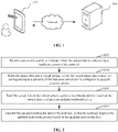
- a picture updating method is applicable to an environment shown in FIG. 1 .
- a terminal 102 communicates with a server 104 over a network.
- the terminal 102 may collect sensor data through a local hardware sensor, and send the data to the server 104.
- the server 104 may write the sensor data into a local virtual sensor.
- a structure of the virtual sensor in the server 104 corresponds to a structure of the hardware sensor in the terminal 102.
- the virtual sensor may be configured to support a sensor service.
- the server 104 may read the sensor data in the virtual sensor, update a multimedia picture based on the sensor data, and generate updated multimedia data.
- the server 104 may send the updated multimedia data to the terminal 102.
- the terminal 102 may locally display the updated multimedia picture corresponding to the updated multimedia data.
- the terminal 102 may be, but is not limited to, personal computers, notebook computers, smartphones, tablet computers, and portable wearable devices.
- the server 104 may be implemented as an independent server, or a server cluster formed by multiple servers, or a cloud server.
- the virtual sensor having a structure corresponding to the structure of the hardware sensor is pre-arranged in the server.
- the virtual sensor is configured to store the sensor data and support the sensor service. Therefore, in a scenario in which the application runs on a cloud server, the server can start the sensor service by using the virtual sensor to control the hardware sensor of the terminal, without a hardware sensor.
- the server can read the sensor data in the virtual sensor, the sensor data being collected by the hardware sensor in response to a user operation and is sent by the terminal.
- the server updates the multimedia picture based on the sensor data, and generates the updated multimedia data.
- the terminal can display the multimedia picture corresponding to the updated multimedia data.
- the picture displayed by the application on the terminal can be updated by the hardware sensor by detecting a user operation on the terminal.
- Cloud gaming also known as gaming on demand, is a type of online gaming technology based on cloud computing technology. Cloud gaming technology enables a thin client with relatively limited capabilities of graphic processing and data computing to run a high-quality game.
- a game is not run on a game terminal of a player, but is run on a cloud server.
- the cloud server renders the gaming scenario into video and audio streams, and transmits the streams to the game terminal of the player over the network.
- the game terminal of the player is unnecessary to have powerful capabilities of graphic processing and data computing, as long as the game terminal has basic capabilities such as the capability to play streaming media and the capability to obtain an instruction inputted by the player and send the instruction to the cloud server.
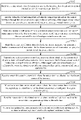
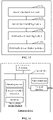
- a picture updating method is provided. Assuming that the method is applied to the server shown in FIG. 1 , the method includes the following steps S202 to S208.
- step S202 sensor data sent by a terminal is received.
- the sensor data is collected by a hardware sensor of the terminal.
- the hardware sensor is a hardware device deployed in the terminal, and is configured to collect data.
- a type of the hardware sensor is not limited, including a gyro sensor, acceleration sensor, gravity sensors, magnetic field sensor, geomagnetic sensor, and the like.
- multiple types of hardware sensors are usually provided to collect different types of data.
- the terminal may obtain a virtual sensor startup instruction through an application client, and send the virtual sensor startup instruction to the server.
- the virtual sensor startup instruction carries a sensor type identifier.
- the server may start up a virtual sensor device indicated by the sensor type identifier, and generate a hardware sensor startup instruction.
- the hardware sensor startup instruction carries the sensor type identifier.
- the terminal may start up a hardware sensor indicated by the sensor type identifier. Then the user can switch a multimedia picture in the application client of the terminal through the hardware sensor. For example, by starting up an acceleration sensor in a speedboat game application, the player can control a forward direction of a speedboat through the acceleration sensor in the terminal, and then switch a currently displayed game picture.
- the user can switch a currently displayed scenic spot picture through the acceleration sensor in the terminal.
- the terminal can obtain the sensor data collected in real time by the hardware sensor and send the sensor data to the server.
- step S204 the sensor data is written into a virtual sensor.
- the virtual sensor has a structure corresponding to a structure of the hardware sensor and is configured to support a sensor service.
- the virtual sensor is a virtual device deployed inside the server.
- the virtual sensor has a structure corresponding to a structure of the hardware sensor and is configured to support the sensor service.
- the sensor service is a function provided by a sensor service module on the server, and is used for controlling the virtual sensor.
- the sensor service module may register the sensor service to a sensor management module on the server.
- the sensor management module is configured to register the sensor service, send the sensor service, and check health status of the sensor service.
- the virtual sensor includes a virtual sensor abstraction layer and a shared memory.
- the virtual sensor is pre-arranged in the server.
- the structure of the virtual sensor corresponds to the structure of the hardware sensor in the terminal.
- the server may write the sensor data into the virtual sensor, so that the sensor data is cached in the virtual sensor.
- an application in the server (corresponding to an application in the terminal) can read the sensor data stored in the virtual sensor by invoking the sensor service.
- the virtual sensor includes a virtual sensor abstraction layer and a shared memory.
- the virtual sensor abstraction layer is configured to provide a virtual sensor list and a sensor interface.
- the shared memory is configured to generate a virtual sensor device.
- the virtual sensor includes a virtual sensor abstraction layer and a shared memory.
- the virtual sensor abstraction layer provides a sensor interface.
- An upper-layer sensor service module can drive and invoke the virtual sensor device by invoking a sensor interface.
- the virtual sensor abstraction layer further provides a virtual sensor list.
- the upper-layer sensor service module can learn currently supported sensor types and corresponding features by searching the virtual sensor list.
- the server When starting up or shutting down a type of virtual sensor, the server first checks whether the type of sensor exists in the virtual sensor list, and proceeds to the next step when the type of sensor is found. If the type of sensor is not found, the server returns a notification message indicating failure of startup or shutdown to the terminal.
- the server may virtualize a hardware sensor device by creating a shared memory.
- the hardware sensor includes a sensor hardware abstraction layer (HAL) and a hardware sensor device.
- the sensor hardware abstraction layer provides multiple sensor interfaces.
- the virtual sensor includes a virtual sensor hardware abstraction layer (that is, virtual sensor abstraction layer) and a shared memory.
- the sensor hardware abstraction layer corresponds to the virtual sensor hardware abstraction layer.
- the hardware sensor device corresponds to the shared memory.
- the virtual sensor hardware abstraction layer also provides multiple sensor interfaces. At least one virtual sensor device can be generated based on the shared memory. For example, all virtual sensor devices may share a shared memory.
- the sensor interface may include an activate interface, a setDelay interface, a poll interface, a parameter setting interface (batch interface), a flush interface, and the like.
- the activate interface is configured to start up or shut down a sensor device.
- the setDelay interface is configured to set a sampling rate of the sensor device, and is invoked for initial setting only.
- the poll interface is configured to read the sensor data.
- the batch interface is configured to set parameters of the sensor device, such as the sampling rate and a maximum reporting delay.
- the flush interface is configured to flush the sensor data. In this way, a virtual sensor having a structure corresponding to the structure of the hardware sensor is provided in the server. The server can successfully star tup the sensor service by the virtual sensor without the hardware sensor.
- step S206 the sensor data is read from the virtual sensor, a multimedia picture is updated based on the sensor data, and updated multimedia data is generated.
- the multimedia picture is a picture obtained by observing a virtual environment from a current viewing angle of the virtual object.
- the virtual environment is a virtual environment displayed when an application on the terminal is run, such as a game picture of a cloud game in a cloud gaming application, a map picture of a scenic spot in a travel application, or the like.
- the virtual object is a movable object in the virtual environment, and may be a virtual character, a virtual animal, or the like.
- the multimedia picture is a picture obtained by rendering based on multiple environment elements in the virtual environment.
- the environment elements are constituent elements of the virtual environment, and may include virtual characters, virtual buildings, virtual tools, and the like.
- the multimedia data is generated by encoding the rendered multimedia picture, and may include audio data, video data, text data, and the like.
- the server may read the sensor data in the virtual sensor through a local application, determine viewing angle adjustment data based on the sensor data through the local application, and update a current multimedia picture corresponding to the application based on the viewing angle adjustment data, so as to obtain an updated multimedia picture.
- the server encodes the updated multimedia picture to obtain updated multimedia data.
- an application backend on the server may write the sensor data into the shared memory in the virtual sensor.
- the application on the server may obtain the sensor data in the shared memory through the virtual sensor abstraction layer by invoking the sensor service.
- step S208 the updated multimedia data is transmitted to the terminal, so that the terminal displays the updated multimedia picture based on the updated multimedia data.
- the server may send the updated multimedia data to the terminal.
- the terminal After receiving the updated multimedia data, the terminal decodes the updated multimedia data to obtain an updated multimedia picture, and displays the updated multimedia picture.
- the terminal runs a cloud gaming client.
- a player can start any cloud game on the cloud gaming client, such as a shooter game.
- a cloud gaming server locally runs an application corresponding to the cloud game.
- FIG. 4 is a schematic diagram of a game configuration interface according to an embodiment.
- the player can trigger a button for starting up a gyro sensor, as shown by a region 402 in FIG. 4 .
- the cloud gaming server can start up a corresponding virtual gyro sensor, and then the terminal can start up a corresponding hardware gyro sensor.
- the player can control the viewing angle during shooting by moving the terminal.
- the hardware gyro sensor on the terminal can collect corresponding sensor data, and send the sensor data to the cloud gaming server.
- the cloud gaming server may write the sensor data into the virtual sensor.
- a shooter game application on the cloud gaming server may read the sensor data in the virtual sensor, adjust a shooting angle based on the sensor data, update a shooting picture, and generate updated multimedia data.
- the cloud gaming client may receive the updated multimedia data returned by the cloud gaming server, and display the updated shooting picture corresponding to the updated multimedia data.
- the player can change the shooting angle and the shooting picture by moving the terminal.
- the player can perform a shooting operation by touching the screen with a finger, and the player is unnecessary to perform other touch operations on the screen to change the shooting angle. This is more approximate to a real shooting scenario in which a shooter adjusts the shooting angle by moving a firearm and shoots by pulling the finger.
- the sensor data sent by the terminal is received.
- the sensor data is collected by the hardware sensor of the terminal.
- the sensor data is written into the virtual sensor.
- the virtual sensor has a structure corresponding to the structure of the hardware sensor and is configured to support the sensor service.
- the sensor data in the virtual sensor is read.
- the multimedia picture is updated based on the sensor data.
- the updated multimedia data is generated.
- the updated multimedia data is transmitted to the terminal, so that the terminal displays the updated multimedia picture based on the updated multimedia data.
- the virtual sensor having a structure corresponding to the structure of the hardware sensor is pre-arranged in the server.
- the virtual sensor may be configured to store the sensor data and support the sensor service.
- the server can start up the sensor service by using the virtual sensor to control the hardware sensor of the terminal, without a hardware sensor.
- the server can read the sensor data in the virtual sensor, the sensor data being collected by the hardware sensor in response to a user operation and being sent by the terminal.
- the server updates the multimedia picture based on the sensor data, and generates the updated multimedia data.
- the terminal can display the multimedia picture corresponding to the updated multimedia data.
- the picture displayed by the application on the terminal can be updated by the hardware sensor by detecting a user operation on the terminal.
- the picture updating method before the sensor data sent by the terminal is received, the picture updating method further includes the following steps S502 and S504.
- step S502 an application startup instruction sent by the terminal is received.
- the application startup instruction carries a terminal identifier and an application identifier of the terminal.
- step S504 in response to the application startup instruction, a target container corresponding to the application identifier is obtained from an idle container pool, the target container is started, and the target container is correlated with the terminal identifier.
- the application startup instruction is used for starting up the target container arranged on the server.
- An application is stored in the target container.
- At least one container may be arranged on the server.
- An operating system runs in the container, and the application runs on the operating system.
- One application is installed in one container.
- the applications installed in different containers may be the same or different.
- the server may correlate the application identifier of the application in the container with the container.
- the containers on the server may be classified into idle containers and serving containers depending on running statuses of the containers.
- the running status of the container includes an idle state and a serving state. When the container is in an idle state, it is indicated that the container is not running and is not allocated to the terminal to run the application, and the container is an idle container. When the container is in a serving state, it is indicated that the container is running and has been allocated to the terminal to run the application, and the container is a serving container.
- An idle container pool includes at least one idle container.
- An application client may run on the terminal.
- the application client may display a list of applications that can be installed and run currently and are supported by the server.
- the list of applications may display information such as application identifier, application rating, and application introduction, to assist users to have a preliminary understanding of each application.
- the terminal may receive a trigger operation performed by the user on any application in the list of applications, and generate an application startup instruction in response to the trigger operation.
- the application startup instruction carries a terminal identifier of the terminal and an application identifier of the application triggered by the user.
- the terminal may send the application startup instruction to the server. After receiving the application startup instruction, the server may allocate a corresponding target container to the terminal.
- the server may, in response to the application startup instruction, search the idle container pool for an idle container correlated with the application identifier, as a target container.
- the server starts up and runs the target container, and correlates the target container with the terminal identifier, so as to allocate the target container to the terminal to serve the terminal.
- the target container may generate a multimedia picture in real time, and transmit multimedia data corresponding to the multimedia picture to the terminal in real time.
- the application client on the terminal may display the corresponding multimedia picture based on the multimedia data.
- the application client on the terminal is a cloud gaming client.
- the cloud gaming client displays a shooter cloud game, a fighting cloud game, and a driving cloud game.
- the user may click the driving cloud game on the cloud gaming client.
- the cloud gaming server can allocate a target container corresponding to the driving cloud game to the terminal, and run the target container. In this way, a game picture corresponding to the driving cloud game can be displayed on the terminal.
- the trigger operation may be a touch operation, cursor operation, keystroke operation, voice operation, or the like.
- the application is installed in the container of the server.
- the container of the server runs the application. In this way, the user is unnecessary to install the application on the terminal, thereby effectively saving storage resources of the terminal.
- the sensor data carries the terminal identifier.
- the process of receiving sensor data sent by a terminal includes: receiving, by using an application proxy, the sensor data sent by the terminal, and inputting the sensor data into the target container based on the terminal identifier.
- the target container contains an application indicated by the application identifier, a sensor service module, a virtual sensor, and an application backend.
- the sensor service module is configured to provide the sensor service.
- the application backend is configured to receive the sensor data inputted by the application proxy, and write the sensor data into the virtual sensor.
- the application is configured to invoke the sensor service module to read the sensor data in the virtual sensor, update the multimedia picture based on the sensor data, and send the updated multimedia picture to the application backend.
- the application backend is further configured to generate the updated multimedia data based on the updated multimedia picture, and send the updated multimedia data to the terminal through the application proxy.
- the server contains the application proxy and the target container.
- the target container contains the application, the sensor service module, the virtual sensor, and the application backend.
- the application and the virtual sensor transmit data through the sensor service module.
- the target container and the application proxy transmit data through the application backend.
- the target container and the terminal transmit data through the application proxy.
- the application proxy may receive the sensor data sent by the terminal, and input the sensor data into the target container.
- the application proxy may input the sensor data into the application backend in the target container.
- the application backend writes the sensor data into the virtual sensor, and caches the sensor data in the virtual sensor.
- the application may invoke the sensor service module to read the sensor data in the virtual sensor.
- the application may update the multimedia picture based on the sensor data to obtain an updated multimedia picture, and send the updated multimedia picture to the application backend.
- the application backend encodes the updated multimedia picture to obtain updated multimedia data, and sends the updated multimedia data to the application proxy.
- the application proxy sends the updated multimedia data to the terminal.
- the application proxy and the terminal transmit data based on Web Real-Time Communication (WebRTC) technology.
- the application proxy may receive, through a WebRTC data channel, the sensor data sent by the terminal.
- the application proxy may send the updated multimedia data to the terminal through a WebRTC video channel.
- the application proxy may compress the updated multimedia data, and send the compressed updated multimedia data to the terminal, thereby reducing the amount of data transmitted over the network and increasing the speed of data transmission.
- orderly data transmission can be performed between the server and the terminal by cooperation between the application, the sensor service module, the virtual sensor, the application backend, the application proxy, and the terminal.
- the picture updating method before the sensor data sent by the terminal is received, the picture updating method further includes the following steps S602 to S606.
- step S602 a virtual sensor control instruction sent by the terminal is received.
- the virtual sensor control instruction carries a sensor type identifier.
- the virtual sensor control instruction is used for controlling an on/off status of the virtual sensor device, and specifically, for starting up the virtual sensor device or shutting down the virtual sensor device.
- the sensor type identifier is an identifier for uniquely identifying the type of the sensor, and may include at least one of numerals, letters, or characters.
- the terminal may display an application configuration interface.
- the application configuration interface displays controls that are configured to trigger a sensor control operation, such as a control configured to control the startup or shutdown of an acceleration sensor.
- a sensor control operation such as a control configured to control the startup or shutdown of an acceleration sensor.
- the terminal When detecting a trigger operation performed by the user on the control, the terminal generates a virtual sensor control instruction based on the sensor type identifier corresponding to the control, and sends the virtual sensor control instruction to the server.
- the terminal may send the virtual sensor control instruction to the application in the target container through an application proxy or an application backend on the server.
- step S604 in response to the virtual sensor control instruction, an on/off status of a target virtual sensor device indicated by a sensor type identifier is updated through a virtual sensor abstraction layer, so as to obtain a current on/off status of the target virtual sensor device.
- the on/off status includes an ON state and an OFF state.
- the ON state and the OFF state are mutually exclusive states.
- the current on/off status is the updated on/off status of the target virtual sensor device.
- the server may modify, through the virtual sensor abstraction layer, the on/off status of the target virtual sensor device indicated by the sensor type identifier from the OFF state to the ON state, or modify the on/off status of the target virtual sensor device indicated by the sensor type identifier from the ON state to the OFF state.
- the virtual sensor control instruction may further carry a specific control type.
- the control type includes startup or shutdown.
- the server modifies the on/off status of the target virtual sensor device based on the control type. For example, if the control type is startup, the server modifies the on/off status of the target virtual sensor device to the ON state when the original on/off status of the target virtual sensor device is the OFF state.
- the server maintains the on/off status of the target virtual sensor device at the ON state when the original on/off status of the target virtual sensor device is the ON state.
- the application in the target container updates, through the virtual sensor abstraction layer, the on/off status of the target virtual sensor device indicated by the sensor type identifier to obtain the current on/off status of the target virtual sensor device.
- step S606 a hardware sensor control instruction is generated based on the current on/off status of the target virtual sensor device, and the hardware sensor control instruction is transmitted to the terminal, so that the terminal synchronizes the on/off status for a target hardware sensor corresponding to the target virtual sensor device based on the current on/off status.
- the hardware sensor control instruction is used for controlling an on/off status of a hardware sensor device, and specifically, for starting up the hardware sensor device or shutting down the hardware sensor device.
- the server After the on/off status of the target virtual sensor device is updated, the server generates a hardware sensor control instruction based on the current on/off status of the target virtual sensor device, and sends the hardware sensor control instruction to the terminal.
- the terminal modifies the on/off status of the target hardware sensor corresponding to the target virtual sensor device to a state that is consistent with the current on/off status of the target virtual sensor device. For example, if the current on/off status of a virtual acceleration sensor device is the ON state, the hardware sensor control instruction is used for instructing the terminal to modify the on/off status of a hardware acceleration sensor to the ON state, that is, to start up the hardware acceleration sensor.
- the application backend on the server generates a hardware sensor control instruction based on the current on/off status of the target virtual sensor device, and transmits the hardware sensor control instruction to the terminal through the application proxy.
- the virtual sensor control instruction sent by the terminal may instruct the server to update the on/off status of the target virtual sensor device, so as to start up or shut down the local virtual sensor device of the server.
- the hardware sensor control instruction which is generated by the server based on the current on/off status of the target virtual sensor device, can instruct the terminal to update the on/off status of the target physical sensor corresponding to the target virtual sensor device, so as to start up or shut down the local hardware sensor of the terminal.
- statuses of the virtual sensor device and the corresponding physical sensor are synchronized, thereby facilitating transmission of the sensor data between the terminal and the server.
- the picture updating method further includes: invoking a sensor creation function in the virtual sensor abstraction layer through a sensor service in response to the virtual sensor control instruction; and generating a sensor interface and a shared memory based on the sensor creation function.
- the sensor creation function is defined in the virtual sensor abstraction layer.
- the sensor creation function is used for generating the sensor interface and the shared memory.
- the application in the target container receives the virtual sensor control instruction for first time, the application invokes the sensor creation function through the sensor service, generates each sensor interface based on the sensor creation function, and generates the shared memory based on the sensor creation function to implement the virtual sensor device. Subsequently, the application can start up or shut down the corresponding virtual sensor device by invoking an activate interface through the sensor service, and read the sensor data by invoking a poll interface through the sensor service.
- a sensors_module_mothods structure in the virtual sensor abstraction layer defines an open sensors function (sensor creation function).
- the application in the target container invokes the open_sensors function in the sensors_module_mothods structure, creates a sensor interface by using the open_sensors function, and creates a shared memory (/dev/shm/sensors) based on a Linux standard interface by using the open_sensors function.
- the process of updating, in response to the virtual sensor control instruction, an on/off status of a target virtual sensor device indicated by the sensor type identifier through the virtual sensor abstraction layer, so as to obtain a current on/off status of the target virtual sensor device includes the following steps S604A to S604B.
- step S604A when the virtual sensor list includes the sensor type identifier, the on/off status of the target virtual sensor device is updated by invoking the sensor interface through the sensor service, so as to obtain the current on/off status of the target virtual sensor device.
- the server may invoke the sensor service to search whether the sensor type identifier exists in the virtual sensor list of the virtual sensor abstraction layer.
- the server can invoke the sensor interface through the sensor service to update the on/off status of the target virtual sensor device. That is, a sensor service module on the server can invoke the sensor interface (activate interface) to update the on/off status of the target virtual sensor device to obtain the current on/off status of the target virtual sensor device.
- the switch status includes an ON state and an OFF state only, the OFF state may be denoted as 0, and the ON state may be denoted as 1.
- the server may denote the on/off status of the target virtual sensor device as 1.
- the application in the target container instructs the sensor service module to invoke the sensor interface to update the on/off status of the target virtual sensor device.
- step S604B the current on/off status of the target virtual sensor device is written into a current on/off status statistics list in the shared memory.
- the current on/off status statistics list includes the current on/off status of multiple virtual sensor devices.
- the server may write the current on/off status of the target virtual sensor device into the current on/off status statistics list in the shared memory. That is, the server may store the current on/off status of the target virtual sensor device into the current on/off status statistics list in the shared memory.
- the current on/off status statistics list includes the current on/off status of multiple virtual sensor devices. The current on/off status statistics list is searched to determine whether each virtual sensor device is currently in an ON state or an OFF state in a timely manner.
- the server performs an on/off status update operation on the target virtual sensor device only when the virtual sensor list includes the sensor type identifier, thereby performing the on/off status update operation effectively.
- the current on/off status of the target virtual sensor device is written into the current on/off status statistics list in the shared memory, thereby being convenient for the terminal to accurately identify and control the target hardware sensor corresponding to the target virtual sensor device subsequently.
- the process of generating a hardware sensor control instruction based on the current on/off status of the target virtual sensor device, and transmitting the hardware sensor control instruction to the terminal, so that the terminal synchronizes the on/off status for a target hardware sensor corresponding to the target virtual sensor device based on the current on/off status include the following steps S606A and S606B.
- step S606A the current on/off status statistics list is read from the shared memory, and a hardware sensor control instruction is generated.
- the hardware sensor control instruction carries the current on/off status statistics list.
- step S606B the hardware sensor control instruction is transmitted to the terminal, so that the terminal obtains a historical on/off status statistics list in response to the hardware sensor control instruction, and updates the on/off status of the target hardware sensor based on a difference between the historical on/off status statistics list and the current on/off status statistics list.
- the current on/off status statistics list is the latest generated on/off status statistics list.
- the historical on/off status statistics list is the on/off status statistics list generated previously.
- the terminal On receipt of a hardware sensor control instruction carrying the on/off status statistics list, the terminal stores the on/off status statistics list locally.
- the server may monitor the on/off status statistics list in the shared memory in real time.
- the server may read the current on/off status statistics list in the shared memory, generate a hardware sensor control instruction carrying the current on/off status statistics list, and send the hardware sensor control instruction to the terminal.
- the terminal may store the current on/off status statistics list locally, obtain the previously stored historical on/off status statistics list locally, and compare the current on/off status statistics list with the historical on/off status statistics list to determine whether the on/off status of the target virtual sensor device is changed, and to determine the current on/off status of the target virtual sensor device.
- the terminal may modify the on/off status of the target hardware sensor corresponding to the target virtual sensor device to a state that is consistent with the current on/off status of the target virtual sensor device. Based on the sensor type identifier, the terminal may determine the target hardware sensor corresponding to the target virtual sensor device. The sensor type identifier of the target virtual sensor device is consistent with the sensor type identifier of the target hardware sensor.
- the application in the target container may obtain the current on/off status of a specified sensor through an activate interface, and store the current on/off status into a 32-bit variable startedSensors in the shared memory.
- Each bit in the startedSensors variable represents one sensor, 0 denotes OFF, and 1 denotes ON.
- the application backend on the server may monitor the change of the on/off status of each sensor in the startedSensors variable in real time through the virtual sensor abstraction layer. Once a change of the startedSensors variable is detected, the application backend on the server sends the startedSensors variable to the application proxy on the server according to a socket protocol, and then sends the variable to the terminal through the application proxy.
- the terminal After receiving the startedSensors variable, the terminal compares the startedSensors variable with the previously stored startedSensors variable. Based on a result of the comparison, the terminal determines the change of the on/off status of each sensor, for example, changing from 0 to 1 or from 1 to 0, and then the terminal starts up or shuts down the corresponding hardware sensor.
- the terminal may determine mSensorNum and mSensors based on the startedSensors variable.
- mSensorNum represents the number of sensors to be started up which is received by the terminal.
- the mSensors array stores types of sensors to be started up. The terminal can start up the sensors through a registerListener function of an Android SDK.
- the sensor data is obtained from an onSensorChanged callback function of the Android SDK, and is sent to the application proxy on the server through a webrtc data channel.
- the application proxy transmits the sensor data to the application backend according to the socket protocol.
- the application backend writes the received sensor data into a queue in the shared memory.
- the virtual sensor hardware abstraction layer reads the sensor data from the queue and sends the sensor data to the application.
- the hardware sensor control instruction carrying the current on/off status statistics list is generated and sent to the terminal. Therefore, the terminal can accurately update the on/off status of the target hardware sensor based on a difference between the historical on/off status statistics list and the current on/off status statistics list.
- the process of writing the sensor data into the virtual sensor includes: writing the sensor data into a tail of the queue in the shared memory, and updating a tail identifier.
- the process of reading the sensor data in the virtual sensor includes: reading the sensor data at a head of the queue, and updating a head identifier.
- the virtual sensor abstraction layer and the application backend transmit the sensor data through the shared memory.
- a queue configured to store the sensor data may be created in the shared memory, and the queue is based on a first-in first-out principle.
- the application backend on the server writes the sensor data to the tail of the queue in the shared memory, and updates a queue tail pointer, that is, updating the queue tail identifier.
- the application in the target container reads the corresponding sensor data at the head of the queue in the shared memory, and updates a queue head pointer, that is, updating the queue head identifier.
- the virtual sensor hardware abstraction layer and the application backend transmit the sensor data (sensors_event_t) through the shared memory (/dev/shm/sensors).
- a queue is created in the shared memory.
- an int-type variable mLastWrapCnt is stored into the shared memory to record a wrap count, that is, the number of wrap-arounds that occur because the tail pointer exceeds the head pointer.
- the sensor data is stored in a queue.
- the tail identifier is updated once a piece of sensor data is written, and the head identifier is updated once a piece of sensor data is read, thereby ensuring orderliness of writing and reading the sensor data.
- the head identifier and the tail identifier are beneficial to subsequently determine and read the latest stored sensor data quickly.
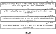
- the process of reading the sensor data in the virtual sensor, updating a multimedia picture based on the sensor data, and generating updated multimedia data include the following steps S1002 to S1008
- step S 1002 a preset rollback threshold is obtained when the number of pieces of the sensor data written into the virtual sensor is greater than a preset write threshold.
- step S1004 the head identifier is updated based on the preset rollback threshold to obtain a target head identifier;
- step S 1006 the sensor data located between the target head identifier and the tail identifier in the queue is used as target sensor data.
- step S1008 the multimedia picture is updated based on the target sensor data, and the updated multimedia data is generated.
- the reading speed of the sensor data is substantially the same as the writing speed of the sensor data.
- the server can update the multimedia picture based on the latest sensor data in real time, so as to respond to the latest movement operation of the user on the terminal in time and implement correct switching of the picture on the terminal in time.
- the sensor data collected by the hardware sensor in real time accumulate on the terminal.
- the terminal sends the accumulated sensor data together to the server.
- the application backend on the server writes the accumulated sensor data together into the queue of the shared memory.
- the application on the server needs to read old sensor data and update the multimedia picture based on the old sensor data, resulting in the response to the latest movement operation of the user on the terminal is delayed, and the correct switching of the picture on the terminal in time is not implemented.
- the application on the server may obtain a preset rollback threshold, and roll back the head identifier based on the preset rollback threshold to obtain a target head identifier.
- the application on the server reads sensor data located between the target head identifier and the tail identifier in the queue as target sensor data.
- the application reads, from the queue, the latest written sensor data of which the number of pieces is equal to the preset rollback threshold.
- the application updates the multimedia picture based on the latest written target sensor data, and generates updated multimedia data.
- the preset rollback threshold may be user-defined as required.
- the queue is empty, the virtual sensor hardware abstraction layer is blocked from reading data and enters a sleep state, waiting for the application backend to write data.
- This scenario usually occurs when the server just begins to run the application.
- the application backend writes data so fast that the tail pointer exceeds the head pointer and wrap-around occurs.
- the application backend adds the mLastWrapCnt variable by 1 to indicate that the wrap count is added by 1.
- wrap-around it is indicated that the reading speed of the virtual sensor abstraction layer is slower than the writing speed of the application backend.
- the terminal When the terminal generates network uplink jitter, resulting in delay jitter of the sent sensor data, it is probable that dozens pieces of sensor data accumulate on the terminal, and then the accumulated sensor data is sent to the application backend instantly.
- the application backend writes the sensor data into the queue, resulting in that the tail pointer exceeds the head pointer and wrap-around occurs.
- the virtual sensor abstraction layer should read the latest written sensor data. Therefore, the head pointer is rolled back by the preset rollback threshold, so that the virtual sensor abstraction layer reads the latest written sensor data. For example, the head pointer is rolled back by 10, so that the virtual sensor abstraction layer reads the 10 pieces of latest written sensor data, thereby avoiding delay of switching the picture caused by slow reading since old sensor data is always read. In addition, subsequently written new data automatically covers the old data stored at the same location.
- a preset rollback threshold is obtained.
- the head identifier of the queue is adjusted based on the preset rollback threshold, thereby ensuring that the latest written sensor data is read quickly, and thus ensuring that the picture is switched correctly and in time.
- the process of updating a multimedia picture based on the sensor data, and generating updated multimedia data includes: obtaining a panoramic picture, the multimedia picture being a picture matching a first viewing angle in the panoramic picture, and the first viewing angle being a current viewing angle; adjusting the first viewing angle based on the sensor data to obtain a second viewing angle; and determining a picture matching the second viewing angle in the panoramic picture, generating multimedia viewing angle update data, and using the multimedia viewing angle update data as the updated multimedia data.
- the process of transmitting the updated multimedia data to the terminal, so that the terminal displays the updated multimedia picture based on the updated multimedia data includes: transmitting the multimedia viewing angle update data to the terminal, so that the terminal switches, based on the multimedia viewing angle update data, a currently displayed picture from the picture matching the first viewing angle to the picture matching the second viewing angle.
- the panoramic picture is a picture that is obtained from observing, by a virtual object, a virtual environment from a 360-degree angle.
- the multimedia picture is a picture that is currently displayed by the terminal after the hardware sensor is started up and before the user changes the status of the terminal in a space, and is a picture that is obtained from observing, by the virtual object, the virtual environment from a current viewing angle (the first viewing angle).
- the multimedia picture is a picture that is obtained from observing towards north by a soldier game character at the current position.
- the multimedia viewing angle update data is the updated multimedia data corresponding to the updated multimedia picture after the viewing angle is updated.
- the sensor data carries a timestamp.
- the server may obtain a panoramic picture corresponding to the timestamp from another server or locally.
- the server may obtain a panoramic picture locally, where the panoramic picture is obtained from observing, by the virtual object, a scenic spot A from a 360-degree angle at a current time instant.
- the server may obtain a panoramic picture from a game server, where the panoramic picture is obtained from observing, by the virtual object, a surrounding game environment from a 360-degree angle at the current time instant.
- the server analyzes the sensor data, determines a moving direction and a moving angle of the terminal, and adjusts the first viewing angle based on the moving direction and the moving angle of the terminal to obtain a second viewing angle. From the panoramic picture, the server may determine a picture that is obtained from observing, by the virtual object at the current position, the virtual environment from the second viewing angle. The server may generate multimedia viewing angle update data, and send the multimedia viewing angle update data to the terminal as the updated multimedia data. After receiving the multimedia viewing angle update data, the terminal may switch, based on the multimedia viewing angle update data, a currently displayed picture from the picture matching the first viewing angle to the picture matching the second viewing angle.
- the viewing angle of the soldier game character is gradually adjusted from the north direction to the east direction, and the terminal gradually switches the displayed picture gradually from the picture matching the north direction to the picture matching the east direction.
- the picture displayed on the terminal can be switched by only moving the terminal, thereby simplifying the operation of the user and improving convenience.
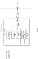
- FIG. 11 is a schematic diagram of an overall architecture corresponding to a picture updating method.
- a cloud game is taken as an example.
- a target container (Android container) runs on a cloud gaming server.
- An operating system in the target container is an Android system.
- the target container includes a cloud gaming application (Game App), a sensor management module (Sensor Manager), a sensor service module (Sensor Service), a virtual sensor, and a cloud gaming backend.
- the virtual sensor includes a virtual sensor hardware abstraction layer (HAL) and a virtual sensor device.
- a virtual sensor having a structure corresponding to the structure of the hardware sensor is provided, thereby ensuring that the cloud gaming application successfully starts up the sensor service.
- the cloud gaming server further includes a cloud gaming proxy.
- the cloud gaming server communicates with the terminal over a network, and the cloud gaming server communicates with a game server over the network.
- the cloud gaming proxy receives a cloud gaming startup instruction sent by the terminal.
- the cloud gaming startup instruction carries a cloud gaming identifier.
- the cloud gaming server runs a target container indicated by the cloud gaming identifier in response to the cloud gaming startup instruction.
- a cloud gaming application indicated by the cloud gaming identifier is installed in the target container.
- the cloud gaming proxy receives a virtual sensor startup instruction sent by the terminal.
- the virtual sensor startup instruction carries a sensor type identifier of a gyro sensor.
- the cloud gaming proxy sends the virtual sensor startup instruction to the cloud gaming application through the cloud gaming backend.
- the cloud gaming application invokes the sensor service module through the sensor management module, invokes, through the sensor service module, a sensor creation function provided by the virtual sensor abstraction layer, generates each sensor interface and a shared memory based on the sensor creation function, generates at least one virtual sensor device through the shared memory, and creates, in the shared memory, a queue that is configured to store sensor data.
- the cloud gaming application starts up the virtual gyro sensor device by invoking an activate interface provided by the virtual sensor abstraction layer, and stores startup status of a virtual gyro sensor device into a 32-bit variable startedSensors in the shared memory through the virtual sensor abstraction layer.
- the startedSensors variable each bit represents one sensor, 0 denotes OFF, and 1 denotes ON.
- the cloud gaming backend sends the startedSensors variable to the cloud gaming proxy according to a socket protocol, and then sends the startedSensors variable to the terminal through the cloud gaming proxy.
- the terminal compares the startedSensors variable with the previously stored startedSensors variable. Based on a result of the comparison, the terminal starts up the corresponding hardware gyro sensor.
- the Queue Length represents the length of the queue.
- an int-type variable mLastWrapCnt is stored into the shared memory to record a wrap count, that is, the number of wrap-arounds that occur because the tail pointer exceeds the head pointer.
- head (head + 1)% (Queue Length)
- the cloud gaming application rolls back the head pointer by a preset rollback threshold, so that the cloud gaming application can read the latest written sensor data of which the number of pieces is equal to the preset rollback threshold.
- the cloud gaming application obtains, from the game server, a panoramic picture and a multimedia picture matching the current viewing angle (the first viewing angle), adjusts the first viewing angle based on the read sensor data to obtain a second viewing angle, determines the updated media picture matching the first viewing angle from the panoramic picture, and sends the updated multimedia picture to the cloud gaming backend.
- the cloud gaming backend encodes the updated multimedia picture to obtain the updated multimedia data, and sends the updated multimedia data to the cloud gaming proxy.
- the cloud gaming proxy sends the updated multimedia data to the terminal. After receiving the updated multimedia data, the terminal decodes and displays the updated multimedia picture.
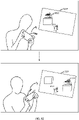
- a user holds a terminal 1200, and the terminal 1200 displays a game picture of a shooter game.
- the user has started a gyro sensor in a game configuration interface.
- the terminal displays a multimedia picture 1210.
- the multimedia picture 1210 is a game picture that is obtained from observing, by a virtual object 1211, a virtual environment from a first viewing angle.
- the multimedia picture 1210 includes a target object 1212.
- the terminal 1200 switches the picture from the multimedia picture 1210 to an updated multimedia picture 1220.
- the updated multimedia picture 1220 is a game picture that is obtained from observing, by the virtual object 1211, the virtual environment from a second viewing angle.
- the updated multimedia picture 1220 includes the target object 1212. Because the viewing angle of the virtual object 1211 is changed, the position of the target object 1212 displayed in the game picture is changed accordingly.
- a picture updating method is provided. Assuming the method is applied to the terminal shown in FIG. 1 , the method includes the following steps S1302 to S1308.
- step S1302 sensor data collected by a local hardware sensor is obtained.
- An application client may run on the terminal.
- the application client may display a list of applications that can be installed and run currently by a server.
- the terminal may receive a trigger operation performed by the user on any application in the list of applications, and generate an application startup instruction in response to the trigger operation.
- the application startup instruction is used for instructing the server to run an idle container in which the application is arranged. Then, the terminal can display an application picture corresponding to the application and sent by the server.
- the terminal may generate a virtual sensor startup instruction in response to a trigger operation on sensor configuration performed by the user in an application picture, and send the virtual sensor startup instruction to the server.
- the virtual sensor startup instruction carries a sensor type identifier.
- the server may start up a virtual sensor device indicated by the sensor type identifier, and generate a hardware sensor startup instruction.
- the hardware sensor startup instruction carries the sensor type identifier.
- the terminal may start up a hardware sensor indicated by the sensor type identifier. Subsequently, when the user changes the status of the terminal in the space, the hardware sensor may collect the corresponding sensor data.
- the sensor data is sent to a server so that the server writes the sensor data into a virtual sensor through an application backend, reads the sensor data in the virtual sensor through an application, updates a multimedia picture based on the sensor data, and generates updated multimedia data through the application backend based on the updated multimedia picture.
- the virtual sensor has a structure corresponding to a structure of the hardware sensor and is configured to support a sensor service.
- the terminal may send the sensor data to the server.
- a virtual sensor having the structure corresponding to the structure of the hardware sensor is pre-arranged in the server.
- the virtual sensor can assist the server in starting up the sensor service.
- the server further includes an application and an application backend. After receiving the sensor data, the server may write the sensor data into the virtual sensor through the application backend, so that the sensor data is cached in the virtual sensor.
- the application in the server may invoke the sensor service to read the sensor data in the virtual sensor, determine viewing angle adjustment data based on the sensor data, and update, based on the viewing angle adjustment data, a multimedia picture corresponding to a current viewing angle.
- the application in the server sends the updated multimedia picture to the application backend in the server.
- the application backend generates, based on the updated multimedia picture, updated multimedia data corresponding to the target viewing angle.
- the target viewing angle is obtained by adjusting the current viewing angle based on the viewing angle adjustment data.
- step S1306 the updated multimedia data returned by the server is received.
- step S1308 the updated multimedia picture is displayed based on the updated multimedia data.
- the terminal may receive the updated multimedia data returned by the server, and display the updated multimedia picture based on the updated multimedia data.
- the viewing angle can be adjusted based on the sensor data that is generated due to changing the status of the terminal in the space by the user, and the application picture observed from the adjusted viewing angle is displayed on the terminal.
- the sensor data collected by the local hardware sensor is obtained.
- the sensor data is sent to the server so that the server writes the sensor data into the virtual sensor through the application backend.
- the sensor data in the virtual sensor is read through the application.
- the multimedia picture is updated based on the sensor data.
- the updated multimedia data is generated through the application backend based on the updated multimedia picture.
- the virtual sensor has the structure corresponding to the structure of the hardware sensor and is configured to support a sensor service, receive the updated multimedia data returned by the server, and display the updated multimedia picture based on the updated multimedia data. In this way, the virtual sensor having the structure corresponding to the structure of the hardware sensor is pre-arranged in the server.
- the virtual sensor is configured to store the sensor data and support the sensor service.
- the server can start up the sensor service by using the virtual sensor to control the hardware sensor of the terminal, without a hardware sensor.
- the server can read the sensor data from the virtual sensor, the sensor data being collected by the hardware sensor in response to a user operation and being sent by the terminal.
- the server updates the multimedia picture based on the sensor data, and generates the updated multimedia data.
- the terminal can display the multimedia picture corresponding to the updated multimedia data.
- the picture displayed by the application on the terminal can be updated by the hardware sensor by detecting a user operation on the terminal.
- the steps in the flowchart are sequentially displayed as indicated by arrows, the steps are not necessarily performed in the order indicated by the arrows. Unless otherwise expressly specified herein, the order of performing the steps is not strictly limited, and the steps may be performed in other order. Moreover, at least a part of the steps in the flowchart may include multiple substeps or stages. The substeps or stages are not necessarily performed at the same time instant, but may be performed at different time instants. The substeps or stages are not necessarily performed sequentially, but may be performed by turns or alternately with other steps or at least a part of substeps or stages of other steps.
- a picture updating apparatus may include a software module or a hardware module or a combination thereof, and may become a part of a computer device.
- the apparatus includes: a sensor data receiving module 1402, a sensor data writing module 1404, a multimedia data generating module 1406, and a multimedia data transmitting module 1408.
- the sensor data receiving module 1402 is configured to receive sensor data sent by a terminal.
- the sensor data is collected by a hardware sensor of the terminal.
- the sensor data writing module 1404 is configured to write the sensor data into a virtual sensor.
- the virtual sensor has a structure corresponding to a structure of the hardware sensor and is configured to support a sensor service.
- the multimedia data generating module 1406 is configured to read the sensor data in the virtual sensor, update a multimedia picture based on the sensor data, and generate updated multimedia data.
- the multimedia data transmitting module 1408 is configured to transmit the updated multimedia data to the terminal, so that the terminal displays the updated multimedia picture based on the updated multimedia data.
- the picture updating apparatus further includes: a first instruction receiving module and a first instruction processing module.
- the first instruction receiving module is configured to receive an application startup instruction sent by the terminal.
- the application startup instruction carries a terminal identifier and an application identifier of the terminal.
- the first instruction processing module is configured to obtain, in response to the application startup instruction, a target container indicated by the application identifier from an idle container pool, start up the target container, and correlate the target container with the terminal identifier.
- the sensor data carries the terminal identifier
- the sensor data receiving module is further configured to receive, by using an application proxy, the sensor data sent by the terminal, and input the sensor data into the target container based on the terminal identifier.
- the target container contains an application, a sensor service module, a virtual sensor, and an application backend.
- the sensor service module is configured to provide the sensor service.
- the application backend is configured to receive the sensor data inputted by the application proxy, and write the sensor data into the virtual sensor.
- the application is configured to invoke the sensor service module to read the sensor data in the virtual sensor, update the multimedia picture based on the sensor data, and send the updated multimedia picture to the application backend.
- the application backend is further configured to generate the updated multimedia data based on the updated multimedia picture, and send the updated multimedia data to the terminal through the application proxy.
- the virtual sensor includes a virtual sensor abstraction layer and a shared memory.
- the virtual sensor abstraction layer is configured to provide a virtual sensor list and a sensor interface.
- the shared memory is configured to generate a virtual sensor device.
- the picture updating apparatus further includes: a second instruction receiving module, a second instruction processing module and an instruction transmitting module.
- the second instruction receiving module is configured to receive a virtual sensor control instruction sent by the terminal.
- the virtual sensor control instruction carries a sensor type identifier.
- the second instruction processing module is configured to update, in response to the virtual sensor control instruction, an on/off status of a target virtual sensor device indicated by a sensor type identifier through a virtual sensor abstraction layer, so as to obtain a current on/off status of the target virtual sensor device.
- the instruction transmitting module is configured to generate a hardware sensor control instruction based on the current on/off status of the target virtual sensor device, and transmit the hardware sensor control instruction to the terminal, so that the terminal synchronizes the on/off status for a target hardware sensor corresponding to the target virtual sensor device based on the current on/off status.
- the second instruction processing module is further configured to invoke a sensor creation function in the virtual sensor abstraction layer through a sensor service in response to the virtual sensor control instruction; and generate a sensor interface and a shared memory based on the sensor creation function.
- the second instruction processing module is further configured to invoke, when the virtual sensor list includes the sensor type identifier, the sensor interface through the sensor service to update the on/off status of the target virtual sensor device, so as to obtain the current on/off status of the target virtual sensor device; and write the current on/off status of the target virtual sensor device into a current on/off status statistics list in the shared memory.
- the current on/off status statistics list includes the current on/off statuses of multiple virtual sensor devices.
- the instruction transmitting module is further configured to: read the current on/off status statistics list in the shared memory, and generate a hardware sensor control instruction, the hardware sensor control instruction carrying the current on/off status statistics list; transmit the hardware sensor control instruction to the terminal, so that the terminal obtains a historical on/off status statistics list in response to the hardware sensor control instruction, and updates the on/off status of the target hardware sensor based on a difference between the historical on/off status statistics list and the current on/off status statistics list.
- the sensor data writing module is further configured to write the sensor data into a tail of the queue in the shared memory, and update a tail identifier.
- the multimedia data generating module is further configured to read the sensor data at a head of the queue, and update a head identifier.
- the multimedia data generating module is further configured to obtain a preset rollback threshold when the number of pieces of the sensor data written into the virtual sensor is greater than a preset write threshold; update the head identifier based on the preset rollback threshold to obtain a target head identifier; use the sensor data located between the target head identifier and the tail identifier in the queue as target sensor data; and update the multimedia picture based on the target sensor data, and generate the updated multimedia data.
- the multimedia data generating module is further configured to: obtain a panoramic picture, the multimedia picture being a picture matching a first viewing angle in the panoramic picture, and the first viewing angle being a current viewing angle; adjust the first viewing angle based on the sensor data to obtain a second viewing angle; and determine a picture matching the second viewing angle in the panoramic picture, generate multimedia viewing angle update data, and use the multimedia viewing angle update data as the updated multimedia data.
- the multimedia data transmitting module is further configured to transmit the multimedia viewing angle update data to the terminal, so that the terminal switches, based on the multimedia viewing angle update data, a currently displayed picture from the picture matching the first viewing angle to the picture matching the second viewing angle.
- a picture updating apparatus may include a software module or a hardware module or a combination thereof and may become a part of a computer device.
- the apparatus includes: a sensor data obtaining module 1502, a sensor data transmitting module 1504, a multimedia data receiving module 1506, and a multimedia picture displaying module 1508.
- the sensor data obtaining module 1502 is configured to obtain sensor data collected by a local hardware sensor.
- the sensor data transmitting module 1504 is configured to send the sensor data to a server so that the server writes the sensor data into a virtual sensor through an application backend, reads the sensor data in the virtual sensor through an application, updates a multimedia picture based on the sensor data, and generates updated multimedia data through the application backend based on the updated multimedia picture.
- the virtual sensor has a structure corresponding to a structure of the hardware sensor and is configured to support a sensor service.
- the multimedia data receiving module 1506 is configured to receive the updated multimedia data returned by the server.
- the multimedia picture displaying module 1508 is configured to display the updated multimedia picture based on the updated multimedia data.
- the modules in the picture updating apparatus may be implemented entirely or partially by software, hardware, or a combination thereof.
- the modules may be embedded in a processor of a computer device in hardware form or independent of the processor, or may be stored in a memory of the computer device in software form, so as to be invoked by the processor to perform the corresponding operations.
- a computer device is provided.
- the computer device may be a server, and a structure diagram of the computer device may be shown in FIG. 16 .
- the computer device includes a processor, a memory, and a network interface that are connected via a system bus.
- the processor of the computer device is configured to provide computing and control capabilities.
- the memory of the computer device includes a non-volatile storage medium and an internal memory.
- the non-volatile storage medium stores an operating system, a computer-readable instruction, and a database.
- the internal memory provides an environment for running of the operating system and the computer-readable instruction in the non-volatile storage medium.
- the database of the computer device is configured to store multiple containers, sensor data, and the like.
- the network interface of the computer device is configured to communicate with an external terminal through a network connection.
- the computer-readable instruction is executed by the processor to implement the picture updating method.
- a computer device is provided.
- the computer device may be a terminal.
- a structure diagram of the computer device may be shown in FIG. 17 .
- the computer device includes a processor, a memory, a communications interface, a display screen, and an input apparatus that are connected via a system bus.
- the processor of the computer device is configured to provide computing and control capabilities.
- the memory of the computer device includes a non-volatile storage medium and an internal memory.
- the non-volatile storage medium stores an operating system and a computer-readable instruction.
- the internal memory provides an environment for running of the operating system and the computer-readable instruction in the non-volatile storage medium.
- the communications interface of the computer device is configured to communicate with an external terminal in a wired or wireless manner.
- the wireless communication may be implemented by WIFI, an operator network, near field communication (NFC), or other technologies.
- the computer-readable instruction is executed by the processor to implement a picture updating method.
- the display screen of the computer device may be a liquid crystal display or an electronic ink display screen.
- the input apparatus of the computer device may be a touch layer that overlays the display screen, or may be a key, a trackball, or a touchpad arranged on a housing of the computer device, or may be an external keyboard, touchpad or mouse or the like.
- FIG. 16 and FIG. 17 are block diagrams of just a part of structures related to the solution of the present disclosure, and do not constitute any limitation on the computer device to which the solution of the present disclosure is applied.
- a specific computer device may include more or fewer components than those shown in the drawings, or some of the components may be combined, or the components may be arranged in a different way.
- a computer device including a memory and one or more processors.
- the memory stores a computer-readable instruction.
- the computer-readable instruction is executed by the one or more processors to implement steps of the method embodiments described above.
- one or more non-volatile computer-readable storage media storing a computer-readable instruction are provided.
- the computer-readable instruction is executed by one or more processors to implement steps of the method embodiments described above.
- a computer program product or a computer program includes a computer-readable instruction.
- the computer-readable instruction is stored in a computer-readable storage medium.
- the processor of the computer device reads the computer-readable instruction from the computer-readable storage medium.
- the processor executes the computer-readable instruction to cause the computer device to perform the steps of the method embodiments.
- a person of ordinary skill in the art may understand that all or some of the procedures of the methods according to the embodiments above may be implemented by relevant hardware instructed by a computer-readable instruction.
- the computer-readable instruction may be stored in a non-volatile computer-readable storage medium.
- the computer-readable instruction is executed to perform steps including the procedures according to the embodiments of the methods.
- a memory, a storage, a database, or another medium used in the embodiments of the present disclosure may include at least one of a non-volatile memory or a volatile memory.
- the non-volatile memory may include a read-only memory (ROM), a magnetic tape, a floppy disk, a flash memory, an optical memory, or the like.
- the volatile memory may include a random access memory (RAM) or an external cache.
- the RAM is in diverse forms, such as a static random access memory (SRAM) or a dynamic random access memory (DRAM).
Landscapes
- Engineering & Computer Science (AREA)
- Multimedia (AREA)
- Human Computer Interaction (AREA)
- Software Systems (AREA)
- Theoretical Computer Science (AREA)
- Physics & Mathematics (AREA)
- General Engineering & Computer Science (AREA)
- General Physics & Mathematics (AREA)
- User Interface Of Digital Computer (AREA)
- Stored Programmes (AREA)
Abstract
Description
- This application claims priority to
Chinese Patent Application No. 202010731481.9, filed with the National Intellectual Property Administration, PRC on July 27, 2020 - The present disclosure relates to the technical field of computer technology, and in particular to a picture updating method and apparatus, a computer device, and a storage medium.
- With the development of computer technology, an application may run on a server without being installed or run on a terminal. For example, cloud gaming is a game mode based on cloud computing. In a running mode of the cloud gaming, all games are run on a server. The server compresses a rendered game picture and transmits the compressed game picture to a terminal over a network.
- In the conventional technology, an application that runs on the terminal usually detects an action of a user by a hardware sensor, so as to update the picture displayed on the terminal. For example, a local game running on the terminal detects an action of shake of the user through an acceleration sensor arranged in the terminal, thereby moving the game picture.
- Because the application runs on the server and the server contains no hardware sensor, the picture displayed on the terminal cannot be updated by detecting an action of the user.
- A picture update method is provided. The method includes:
- receiving sensor data sent by a terminal, where the sensor data is collected by a hardware sensor of the terminal;
- writing the sensor data into a virtual sensor, where the virtual sensor has a structure corresponding to a structure of the hardware sensor and is configured to support a sensor service;
- reading the sensor data in the virtual sensor, updating a multimedia picture based on the sensor data, and generating updated multimedia data; and
- transmitting the updated multimedia data to the terminal, so that the terminal displays the updated multimedia picture based on the updated multimedia data.
- In an embodiment, the generating a hardware sensor control instruction based on the current on/off status of the target virtual sensor device, and transmitting the hardware sensor control instruction to the terminal, so that the terminal synchronizes the on/off status for a target hardware sensor corresponding to the target virtual sensor device based on the current on/off status, includes:
reading the current on/off status statistics list in the shared memory, and generating a hardware sensor control instruction, where the hardware sensor control instruction carries the current switch status statistics list; transmitting the hardware sensor control instruction to the terminal, so that the terminal obtains a historical on/off status statistics list in response to the hardware sensor control instruction, and updates the on/off status of the target hardware sensor based on a difference between the historical on/off status statistics list and the current on/off status statistics list. - A picture update apparatus is provided. The apparatus includes:
- a sensor data receiving module, configured to receive sensor data sent by a terminal, where the sensor data is collected by a hardware sensor of the terminal;
- a sensor data writing module, configured to write the sensor data into a virtual sensor, where the virtual sensor has a structure corresponding to a structure of the hardware sensor and is configured to support a sensor service;
- a multimedia data generating module, configured to read the sensor data in the virtual sensor, update a multimedia picture based on the sensor data, and generate updated multimedia data; and
- a multimedia data transmitting module, configured to transmit the updated multimedia data to the terminal, so that the terminal displays the updated multimedia picture based on the updated multimedia data.
- A computer device including a memory and a processor is provided. The memory stores a computer-readable instruction. The computer-readable instruction is executed by the processor to implement the following operations:
- receiving sensor data sent by a terminal, where the sensor data is collected by a hardware sensor of the terminal;
- writing the sensor data into a virtual sensor, where the virtual sensor has a structure corresponding to a structure of the real sensor and is configured to support a sensor service;
- reading the sensor data in the virtual sensor, updating a multimedia picture based on the sensor data, and generating updated multimedia data; and
- transmitting the updated multimedia data to the terminal, so that the terminal displays the updated multimedia picture based on the updated multimedia data.
- A computer-readable storage medium is provided. The computer-readable storage medium stores a computer-readable instruction. The computer-readable instruction is executed by the processor to implements the following operations:
- receiving sensor data sent by a terminal, where the sensor data is collected by a hardware sensor of the terminal;
- writing the sensor data into a virtual sensor, where the virtual sensor has a structure corresponding to a structure of the hardware sensor and is configured to support a sensor service;
- reading the sensor data in the virtual sensor, updating a multimedia picture based on the sensor data, and generating updated multimedia data; and
- transmitting the updated multimedia data to the terminal, so that the terminal displays the updated multimedia picture based on the updated multimedia data.
- A picture update method is provided. The method includes:
- obtaining sensor data collected by a local hardware sensor;
- sending the sensor data to a server so that the server writes the sensor data into a virtual sensor through an application backend, reads the sensor data in the virtual sensor through an application, updates a multimedia picture based on the sensor data, and generating updated multimedia data through the application backend based on the updated multimedia picture, where the virtual sensor has a structure corresponding to a structure of the hardware sensor and is configured to support a sensor service;
- receiving the updated multimedia data transmitted by the server; and
- displaying the updated multimedia picture based on the updated multimedia data.
- A picture update apparatus is provided. The apparatus includes:
- a sensor data obtaining module, configured to obtain sensor data collected by a local hardware sensor;
- a sensor data transmitting module, configured to send the sensor data to a server so that the server writes the sensor data into a virtual sensor through an application backend, reads the sensor data in the virtual sensor through an application, updates a multimedia picture based on the sensor data, and generates updated multimedia data through the application backend based on the updated multimedia picture, where the virtual sensor has a structure corresponding to a structure of the hardware sensor and is configured to support a sensor service;
- a multimedia data receiving module, configured to receive the updated multimedia data transmitted by the server; and
- a multimedia picture displaying module, configured to display the updated multimedia picture based on the updated multimedia data.
- A computer device including a memory and a processor is provided. The memory stores a computer-readable instruction. The computer-readable instruction is executed by the processor to implement the following operations:
- obtaining sensor data collected by a local hardware sensor;
- sending the sensor data to a server so that the server writes the sensor data into a virtual sensor through an application backend, reads the sensor data in the virtual sensor through an application, updates a multimedia picture based on the sensor data, and generates updated multimedia data through the application backend based on the updated multimedia picture, where the virtual sensor has a structure corresponding to a structure of the hardware sensor and is configured to support a sensor service;
- receiving the updated multimedia data transmitted by the server; and
- displaying the updated multimedia picture based on the updated multimedia data.
- A computer-readable storage medium is provided. The computer-readable storage medium stores a computer-readable instruction. The computer-readable instruction is executed by a processor to implement the following operations:
- obtaining sensor data collected by a local hardware sensor;
- sending the sensor data to a server so that the server writes the sensor data into a virtual sensor through an application backend, reads the sensor data in the virtual sensor through an application, updates a multimedia picture based on the sensor data, and generates updated multimedia data through the application backend based on the updated multimedia picture, where the virtual sensor has a structure corresponding to a structure of the hardware sensor and is configured to support a sensor service;
- receiving the updated multimedia data transmitted by the server; and
- displaying the updated multimedia picture based on the updated multimedia data.
- A computer program product or a computer program is provided. The computer program product or computer program includes a computer-readable instruction. The computer-readable instruction is stored in a computer-readable storage medium. A processor of the computer device reads the computer-readable instruction from the computer-readable storage medium. The processor executes the computer-readable instruction, so that the computer device performs the picture update method.
- To describe the technical solutions in the embodiments of the present disclosure clearer, the drawings to be used in the embodiments are introduced briefly. Apparently, the drawings described below show merely a part of embodiments of the present disclosure. A person skilled in the art may derive other drawings according to these drawings without creative effort.
-
FIG. 1 is a diagram of an application environment of a picture updating method according to an embodiment. -
FIG. 2 is a schematic flowchart of a picture updating method according to an embodiment. -
FIG. 3 is a schematic structural diagram of a virtual sensor and a hardware sensor according to an embodiment. -
FIG. 4 is a schematic diagram of a cloud gaming setting interface according to an embodiment. -
FIG. 5 is a schematic flowchart of starting up a target container according to an embodiment. -
FIG. 6 is a schematic flowchart of controlling a virtual sensor and a hardware sensor according to an embodiment. -
FIG. 7 is a schematic flowchart of controlling a virtual sensor and a hardware sensor according to another embodiment. -
FIG. 8 is a schematic diagram showing a principle for monitoring on/off status of a sensor according to an embodiment. -
FIG. 9 is a schematic diagram showing a principle of transmission of sensor data according to an embodiment. -
FIG. 10 is a schematic flowchart of filtering sensor data according to an embodiment. -
FIG. 11 is a schematic diagram of an overall architecture of a picture updating method according to an embodiment. -
FIG. 12 is a schematic diagram of a picture updating interface of a terminal according to an embodiment. -
FIG. 13 is a schematic flowchart of a picture updating method according to another embodiment. -
FIG. 14 is a structural block diagram of a picture updating apparatus according to an embodiment. -
FIG. 15 is a structural block diagram of a picture updating apparatus according to another embodiment. -
FIG. 16 is a structure diagram of a computer device according to an embodiment. -
FIG. 17 is a structure diagram of a computer device according to an embodiment. - To make the objectives, technical solutions, and advantages of the present disclosure clearer, the present disclosure is described in detail with reference to drawings and embodiments. It should be understood that the specific embodiments described herein are merely intended to explain the present disclosure rather than limit the present disclosure.
- A picture updating method according to the present disclosure is applicable to an environment shown in
FIG. 1 . In the drawing, a terminal 102 communicates with aserver 104 over a network. The terminal 102 may collect sensor data through a local hardware sensor, and send the data to theserver 104. Theserver 104 may write the sensor data into a local virtual sensor. A structure of the virtual sensor in theserver 104 corresponds to a structure of the hardware sensor in theterminal 102. The virtual sensor may be configured to support a sensor service. Theserver 104 may read the sensor data in the virtual sensor, update a multimedia picture based on the sensor data, and generate updated multimedia data. Theserver 104 may send the updated multimedia data to the terminal 102. After receiving the updated multimedia data, the terminal 102 may locally display the updated multimedia picture corresponding to the updated multimedia data. - The terminal 102 may be, but is not limited to, personal computers, notebook computers, smartphones, tablet computers, and portable wearable devices. The
server 104 may be implemented as an independent server, or a server cluster formed by multiple servers, or a cloud server. - In the picture updating method described above, the virtual sensor having a structure corresponding to the structure of the hardware sensor is pre-arranged in the server. The virtual sensor is configured to store the sensor data and support the sensor service. Therefore, in a scenario in which the application runs on a cloud server, the server can start the sensor service by using the virtual sensor to control the hardware sensor of the terminal, without a hardware sensor. The server can read the sensor data in the virtual sensor, the sensor data being collected by the hardware sensor in response to a user operation and is sent by the terminal. The server updates the multimedia picture based on the sensor data, and generates the updated multimedia data. After receiving the updated multimedia data, the terminal can display the multimedia picture corresponding to the updated multimedia data. Finally, in this scenario, the picture displayed by the application on the terminal can be updated by the hardware sensor by detecting a user operation on the terminal.
- Cloud gaming, also known as gaming on demand, is a type of online gaming technology based on cloud computing technology. Cloud gaming technology enables a thin client with relatively limited capabilities of graphic processing and data computing to run a high-quality game. In a cloud gaming scenario, a game is not run on a game terminal of a player, but is run on a cloud server. The cloud server renders the gaming scenario into video and audio streams, and transmits the streams to the game terminal of the player over the network. The game terminal of the player is unnecessary to have powerful capabilities of graphic processing and data computing, as long as the game terminal has basic capabilities such as the capability to play streaming media and the capability to obtain an instruction inputted by the player and send the instruction to the cloud server.
- In an embodiment, as shown in
FIG. 2 , a picture updating method is provided. Assuming that the method is applied to the server shown inFIG. 1 , the method includes the following steps S202 to S208. - In step S202, sensor data sent by a terminal is received. The sensor data is collected by a hardware sensor of the terminal.
- The hardware sensor is a hardware device deployed in the terminal, and is configured to collect data. A type of the hardware sensor is not limited, including a gyro sensor, acceleration sensor, gravity sensors, magnetic field sensor, geomagnetic sensor, and the like. In a terminal, multiple types of hardware sensors are usually provided to collect different types of data.
- The terminal may obtain a virtual sensor startup instruction through an application client, and send the virtual sensor startup instruction to the server. The virtual sensor startup instruction carries a sensor type identifier. After receiving the virtual sensor startup instruction, the server may start up a virtual sensor device indicated by the sensor type identifier, and generate a hardware sensor startup instruction. The hardware sensor startup instruction carries the sensor type identifier. After receiving the hardware sensor startup instruction, the terminal may start up a hardware sensor indicated by the sensor type identifier. Then the user can switch a multimedia picture in the application client of the terminal through the hardware sensor. For example, by starting up an acceleration sensor in a speedboat game application, the player can control a forward direction of a speedboat through the acceleration sensor in the terminal, and then switch a currently displayed game picture. By starting up an acceleration sensor in a travel map application, the user can switch a currently displayed scenic spot picture through the acceleration sensor in the terminal. After the hardware sensor is started up, the terminal can obtain the sensor data collected in real time by the hardware sensor and send the sensor data to the server.
- In step S204, the sensor data is written into a virtual sensor. The virtual sensor has a structure corresponding to a structure of the hardware sensor and is configured to support a sensor service.
- The virtual sensor is a virtual device deployed inside the server. The virtual sensor has a structure corresponding to a structure of the hardware sensor and is configured to support the sensor service. The sensor service is a function provided by a sensor service module on the server, and is used for controlling the virtual sensor. The sensor service module may register the sensor service to a sensor management module on the server. The sensor management module is configured to register the sensor service, send the sensor service, and check health status of the sensor service. The virtual sensor includes a virtual sensor abstraction layer and a shared memory.
- The virtual sensor is pre-arranged in the server. The structure of the virtual sensor corresponds to the structure of the hardware sensor in the terminal. After receiving the sensor data, the server may write the sensor data into the virtual sensor, so that the sensor data is cached in the virtual sensor. Subsequently, an application in the server (corresponding to an application in the terminal) can read the sensor data stored in the virtual sensor by invoking the sensor service.
- In an embodiment, the virtual sensor includes a virtual sensor abstraction layer and a shared memory. The virtual sensor abstraction layer is configured to provide a virtual sensor list and a sensor interface. The shared memory is configured to generate a virtual sensor device.
- The virtual sensor includes a virtual sensor abstraction layer and a shared memory. The virtual sensor abstraction layer provides a sensor interface. An upper-layer sensor service module can drive and invoke the virtual sensor device by invoking a sensor interface. The virtual sensor abstraction layer further provides a virtual sensor list. The upper-layer sensor service module can learn currently supported sensor types and corresponding features by searching the virtual sensor list. When starting up or shutting down a type of virtual sensor, the server first checks whether the type of sensor exists in the virtual sensor list, and proceeds to the next step when the type of sensor is found. If the type of sensor is not found, the server returns a notification message indicating failure of startup or shutdown to the terminal. In addition, the server may virtualize a hardware sensor device by creating a shared memory.
- Reference is made to
FIG. 3 which is a schematic structural diagram of a hardware sensor and a virtual sensor according to an embodiment. Referring toFIG. 3 , the hardware sensor includes a sensor hardware abstraction layer (HAL) and a hardware sensor device. The sensor hardware abstraction layer provides multiple sensor interfaces. The virtual sensor includes a virtual sensor hardware abstraction layer (that is, virtual sensor abstraction layer) and a shared memory. The sensor hardware abstraction layer corresponds to the virtual sensor hardware abstraction layer. The hardware sensor device corresponds to the shared memory. Similarly, the virtual sensor hardware abstraction layer also provides multiple sensor interfaces. At least one virtual sensor device can be generated based on the shared memory. For example, all virtual sensor devices may share a shared memory. All operations performed by the sensor service module on the virtual sensor device by invoking the sensor interface can be implemented by the virtual sensor abstraction layer by performing corresponding operations on the shared memory. The sensor interface may include an activate interface, a setDelay interface, a poll interface, a parameter setting interface (batch interface), a flush interface, and the like. The activate interface is configured to start up or shut down a sensor device. The setDelay interface is configured to set a sampling rate of the sensor device, and is invoked for initial setting only. The poll interface is configured to read the sensor data. The batch interface is configured to set parameters of the sensor device, such as the sampling rate and a maximum reporting delay. The flush interface is configured to flush the sensor data. In this way, a virtual sensor having a structure corresponding to the structure of the hardware sensor is provided in the server. The server can successfully star tup the sensor service by the virtual sensor without the hardware sensor. - In step S206, the sensor data is read from the virtual sensor, a multimedia picture is updated based on the sensor data, and updated multimedia data is generated.
- The multimedia picture is a picture obtained by observing a virtual environment from a current viewing angle of the virtual object. The virtual environment is a virtual environment displayed when an application on the terminal is run, such as a game picture of a cloud game in a cloud gaming application, a map picture of a scenic spot in a travel application, or the like. The virtual object is a movable object in the virtual environment, and may be a virtual character, a virtual animal, or the like. The multimedia picture is a picture obtained by rendering based on multiple environment elements in the virtual environment. The environment elements are constituent elements of the virtual environment, and may include virtual characters, virtual buildings, virtual tools, and the like. The multimedia data is generated by encoding the rendered multimedia picture, and may include audio data, video data, text data, and the like.
- The server may read the sensor data in the virtual sensor through a local application, determine viewing angle adjustment data based on the sensor data through the local application, and update a current multimedia picture corresponding to the application based on the viewing angle adjustment data, so as to obtain an updated multimedia picture. The server encodes the updated multimedia picture to obtain updated multimedia data.
- In an embodiment, an application backend on the server may write the sensor data into the shared memory in the virtual sensor. The application on the server may obtain the sensor data in the shared memory through the virtual sensor abstraction layer by invoking the sensor service.
- In step S208, the updated multimedia data is transmitted to the terminal, so that the terminal displays the updated multimedia picture based on the updated multimedia data.
- The server may send the updated multimedia data to the terminal. After receiving the updated multimedia data, the terminal decodes the updated multimedia data to obtain an updated multimedia picture, and displays the updated multimedia picture.
- For example, in a cloud gaming scenario, the terminal runs a cloud gaming client. A player can start any cloud game on the cloud gaming client, such as a shooter game. Then a cloud gaming server locally runs an application corresponding to the cloud game. Reference is made to
FIG. 4 which is a schematic diagram of a game configuration interface according to an embodiment. In the game configuration interface of the shooter game, the player can trigger a button for starting up a gyro sensor, as shown by aregion 402 inFIG. 4 . Then the cloud gaming server can start up a corresponding virtual gyro sensor, and then the terminal can start up a corresponding hardware gyro sensor. Then the player can control the viewing angle during shooting by moving the terminal. When the player moves the terminal, the hardware gyro sensor on the terminal can collect corresponding sensor data, and send the sensor data to the cloud gaming server. After receiving the sensor data, the cloud gaming server may write the sensor data into the virtual sensor. A shooter game application on the cloud gaming server may read the sensor data in the virtual sensor, adjust a shooting angle based on the sensor data, update a shooting picture, and generate updated multimedia data. The cloud gaming client may receive the updated multimedia data returned by the cloud gaming server, and display the updated shooting picture corresponding to the updated multimedia data. In this way, compared with the conventional technology in which the player has to change the shooting angle and the shooting picture by touching a screen with a finger, according to embodiments of the present disclosure, the player can change the shooting angle and the shooting picture by moving the terminal. In addition, the player can perform a shooting operation by touching the screen with a finger, and the player is unnecessary to perform other touch operations on the screen to change the shooting angle. This is more approximate to a real shooting scenario in which a shooter adjusts the shooting angle by moving a firearm and shoots by pulling the finger. - In the picture updating method described above, the sensor data sent by the terminal is received. The sensor data is collected by the hardware sensor of the terminal. The sensor data is written into the virtual sensor. The virtual sensor has a structure corresponding to the structure of the hardware sensor and is configured to support the sensor service. The sensor data in the virtual sensor is read. The multimedia picture is updated based on the sensor data. The updated multimedia data is generated. The updated multimedia data is transmitted to the terminal, so that the terminal displays the updated multimedia picture based on the updated multimedia data. In this way, the virtual sensor having a structure corresponding to the structure of the hardware sensor is pre-arranged in the server. The virtual sensor may be configured to store the sensor data and support the sensor service. Therefore, in a scenario in which the application runs on a cloud server, the server can start up the sensor service by using the virtual sensor to control the hardware sensor of the terminal, without a hardware sensor. The server can read the sensor data in the virtual sensor, the sensor data being collected by the hardware sensor in response to a user operation and being sent by the terminal. The server updates the multimedia picture based on the sensor data, and generates the updated multimedia data. After receiving the updated multimedia data, the terminal can display the multimedia picture corresponding to the updated multimedia data. Finally, in this scenario, the picture displayed by the application on the terminal can be updated by the hardware sensor by detecting a user operation on the terminal.
- In an embodiment, as shown in
FIG. 5 , before the sensor data sent by the terminal is received, the picture updating method further includes the following steps S502 and S504. - In step S502, an application startup instruction sent by the terminal is received. The application startup instruction carries a terminal identifier and an application identifier of the terminal.
- In step S504, in response to the application startup instruction, a target container corresponding to the application identifier is obtained from an idle container pool, the target container is started, and the target container is correlated with the terminal identifier.
- The application startup instruction is used for starting up the target container arranged on the server. An application is stored in the target container. At least one container may be arranged on the server. An operating system runs in the container, and the application runs on the operating system. One application is installed in one container. The applications installed in different containers may be the same or different. The server may correlate the application identifier of the application in the container with the container. The containers on the server may be classified into idle containers and serving containers depending on running statuses of the containers. The running status of the container includes an idle state and a serving state. When the container is in an idle state, it is indicated that the container is not running and is not allocated to the terminal to run the application, and the container is an idle container. When the container is in a serving state, it is indicated that the container is running and has been allocated to the terminal to run the application, and the container is a serving container. An idle container pool includes at least one idle container.
- An application client may run on the terminal. The application client may display a list of applications that can be installed and run currently and are supported by the server. The list of applications may display information such as application identifier, application rating, and application introduction, to assist users to have a preliminary understanding of each application. The terminal may receive a trigger operation performed by the user on any application in the list of applications, and generate an application startup instruction in response to the trigger operation. The application startup instruction carries a terminal identifier of the terminal and an application identifier of the application triggered by the user. The terminal may send the application startup instruction to the server. After receiving the application startup instruction, the server may allocate a corresponding target container to the terminal. The server may, in response to the application startup instruction, search the idle container pool for an idle container correlated with the application identifier, as a target container. The server starts up and runs the target container, and correlates the target container with the terminal identifier, so as to allocate the target container to the terminal to serve the terminal. After being started up, the target container may generate a multimedia picture in real time, and transmit multimedia data corresponding to the multimedia picture to the terminal in real time. The application client on the terminal may display the corresponding multimedia picture based on the multimedia data.
- For example, the application client on the terminal is a cloud gaming client. The cloud gaming client displays a shooter cloud game, a fighting cloud game, and a driving cloud game. The user may click the driving cloud game on the cloud gaming client. Then the cloud gaming server can allocate a target container corresponding to the driving cloud game to the terminal, and run the target container. In this way, a game picture corresponding to the driving cloud game can be displayed on the terminal. The trigger operation may be a touch operation, cursor operation, keystroke operation, voice operation, or the like.
- In this embodiment, the application is installed in the container of the server. The container of the server runs the application. In this way, the user is unnecessary to install the application on the terminal, thereby effectively saving storage resources of the terminal.
- In an embodiment, the sensor data carries the terminal identifier. The process of receiving sensor data sent by a terminal includes: receiving, by using an application proxy, the sensor data sent by the terminal, and inputting the sensor data into the target container based on the terminal identifier. The target container contains an application indicated by the application identifier, a sensor service module, a virtual sensor, and an application backend. The sensor service module is configured to provide the sensor service. The application backend is configured to receive the sensor data inputted by the application proxy, and write the sensor data into the virtual sensor. The application is configured to invoke the sensor service module to read the sensor data in the virtual sensor, update the multimedia picture based on the sensor data, and send the updated multimedia picture to the application backend. The application backend is further configured to generate the updated multimedia data based on the updated multimedia picture, and send the updated multimedia data to the terminal through the application proxy.
- The server contains the application proxy and the target container. The target container contains the application, the sensor service module, the virtual sensor, and the application backend. The application and the virtual sensor transmit data through the sensor service module. The target container and the application proxy transmit data through the application backend. The target container and the terminal transmit data through the application proxy. The application proxy may receive the sensor data sent by the terminal, and input the sensor data into the target container. The application proxy may input the sensor data into the application backend in the target container. The application backend writes the sensor data into the virtual sensor, and caches the sensor data in the virtual sensor. The application may invoke the sensor service module to read the sensor data in the virtual sensor. The application may update the multimedia picture based on the sensor data to obtain an updated multimedia picture, and send the updated multimedia picture to the application backend. The application backend encodes the updated multimedia picture to obtain updated multimedia data, and sends the updated multimedia data to the application proxy. The application proxy sends the updated multimedia data to the terminal.
- In an embodiment, the application proxy and the terminal transmit data based on Web Real-Time Communication (WebRTC) technology. The application proxy may receive, through a WebRTC data channel, the sensor data sent by the terminal. The application proxy may send the updated multimedia data to the terminal through a WebRTC video channel. Further, the application proxy may compress the updated multimedia data, and send the compressed updated multimedia data to the terminal, thereby reducing the amount of data transmitted over the network and increasing the speed of data transmission.
- In this embodiment, orderly data transmission can be performed between the server and the terminal by cooperation between the application, the sensor service module, the virtual sensor, the application backend, the application proxy, and the terminal.
- In an embodiment, as shown in
FIG. 6 , before the sensor data sent by the terminal is received, the picture updating method further includes the following steps S602 to S606. - In step S602, a virtual sensor control instruction sent by the terminal is received. The virtual sensor control instruction carries a sensor type identifier.
- The virtual sensor control instruction is used for controlling an on/off status of the virtual sensor device, and specifically, for starting up the virtual sensor device or shutting down the virtual sensor device. The sensor type identifier is an identifier for uniquely identifying the type of the sensor, and may include at least one of numerals, letters, or characters.
- The terminal may display an application configuration interface. The application configuration interface displays controls that are configured to trigger a sensor control operation, such as a control configured to control the startup or shutdown of an acceleration sensor. When detecting a trigger operation performed by the user on the control, the terminal generates a virtual sensor control instruction based on the sensor type identifier corresponding to the control, and sends the virtual sensor control instruction to the server. In an embodiment, the terminal may send the virtual sensor control instruction to the application in the target container through an application proxy or an application backend on the server.
- In step S604, in response to the virtual sensor control instruction, an on/off status of a target virtual sensor device indicated by a sensor type identifier is updated through a virtual sensor abstraction layer, so as to obtain a current on/off status of the target virtual sensor device.
- The on/off status includes an ON state and an OFF state. The ON state and the OFF state are mutually exclusive states. The current on/off status is the updated on/off status of the target virtual sensor device.
- After receiving the virtual sensor control instruction, the server may modify, through the virtual sensor abstraction layer, the on/off status of the target virtual sensor device indicated by the sensor type identifier from the OFF state to the ON state, or modify the on/off status of the target virtual sensor device indicated by the sensor type identifier from the ON state to the OFF state. Certainly, the virtual sensor control instruction may further carry a specific control type. The control type includes startup or shutdown. After receiving the virtual sensor control instruction, the server modifies the on/off status of the target virtual sensor device based on the control type. For example, if the control type is startup, the server modifies the on/off status of the target virtual sensor device to the ON state when the original on/off status of the target virtual sensor device is the OFF state. The server maintains the on/off status of the target virtual sensor device at the ON state when the original on/off status of the target virtual sensor device is the ON state. In an embodiment, after receiving the virtual sensor control instruction, the application in the target container updates, through the virtual sensor abstraction layer, the on/off status of the target virtual sensor device indicated by the sensor type identifier to obtain the current on/off status of the target virtual sensor device.
- In step S606, a hardware sensor control instruction is generated based on the current on/off status of the target virtual sensor device, and the hardware sensor control instruction is transmitted to the terminal, so that the terminal synchronizes the on/off status for a target hardware sensor corresponding to the target virtual sensor device based on the current on/off status.
- The hardware sensor control instruction is used for controlling an on/off status of a hardware sensor device, and specifically, for starting up the hardware sensor device or shutting down the hardware sensor device.
- After the on/off status of the target virtual sensor device is updated, the server generates a hardware sensor control instruction based on the current on/off status of the target virtual sensor device, and sends the hardware sensor control instruction to the terminal. After receiving the hardware sensor control instruction, the terminal modifies the on/off status of the target hardware sensor corresponding to the target virtual sensor device to a state that is consistent with the current on/off status of the target virtual sensor device. For example, if the current on/off status of a virtual acceleration sensor device is the ON state, the hardware sensor control instruction is used for instructing the terminal to modify the on/off status of a hardware acceleration sensor to the ON state, that is, to start up the hardware acceleration sensor. In an embodiment, the application backend on the server generates a hardware sensor control instruction based on the current on/off status of the target virtual sensor device, and transmits the hardware sensor control instruction to the terminal through the application proxy.
- In this embodiment, the virtual sensor control instruction sent by the terminal may instruct the server to update the on/off status of the target virtual sensor device, so as to start up or shut down the local virtual sensor device of the server. The hardware sensor control instruction, which is generated by the server based on the current on/off status of the target virtual sensor device, can instruct the terminal to update the on/off status of the target physical sensor corresponding to the target virtual sensor device, so as to start up or shut down the local hardware sensor of the terminal. Finally, statuses of the virtual sensor device and the corresponding physical sensor are synchronized, thereby facilitating transmission of the sensor data between the terminal and the server.
- In an embodiment, after receiving the virtual sensor control instruction sent by the terminal, the picture updating method further includes: invoking a sensor creation function in the virtual sensor abstraction layer through a sensor service in response to the virtual sensor control instruction; and generating a sensor interface and a shared memory based on the sensor creation function.
- The sensor creation function is defined in the virtual sensor abstraction layer. The sensor creation function is used for generating the sensor interface and the shared memory. When the application in the target container receives the virtual sensor control instruction for first time, the application invokes the sensor creation function through the sensor service, generates each sensor interface based on the sensor creation function, and generates the shared memory based on the sensor creation function to implement the virtual sensor device. Subsequently, the application can start up or shut down the corresponding virtual sensor device by invoking an activate interface through the sensor service, and read the sensor data by invoking a poll interface through the sensor service.
- In an embodiment, a sensors_module_mothods structure in the virtual sensor abstraction layer defines an open sensors function (sensor creation function). When invoking the open function through the sensor service, the application in the target container invokes the open_sensors function in the sensors_module_mothods structure, creates a sensor interface by using the open_sensors function, and creates a shared memory (/dev/shm/sensors) based on a Linux standard interface by using the open_sensors function.
- In an embodiment, as shown in
FIG. 7 , the process of updating, in response to the virtual sensor control instruction, an on/off status of a target virtual sensor device indicated by the sensor type identifier through the virtual sensor abstraction layer, so as to obtain a current on/off status of the target virtual sensor device, includes the following steps S604A to S604B. - In step S604A, when the virtual sensor list includes the sensor type identifier, the on/off status of the target virtual sensor device is updated by invoking the sensor interface through the sensor service, so as to obtain the current on/off status of the target virtual sensor device.
- After receiving the virtual sensor control instruction, the server may invoke the sensor service to search whether the sensor type identifier exists in the virtual sensor list of the virtual sensor abstraction layer. When the sensor type identifier exists, it is determined that the server currently supports the target virtual sensor device indicated by the sensor type identifier. Therefore, the server can invoke the sensor interface through the sensor service to update the on/off status of the target virtual sensor device. That is, a sensor service module on the server can invoke the sensor interface (activate interface) to update the on/off status of the target virtual sensor device to obtain the current on/off status of the target virtual sensor device. For example, because the switch status includes an ON state and an OFF state only, the OFF state may be denoted as 0, and the ON state may be denoted as 1. If the virtual sensor control instruction is used to start up the target virtual sensor device, the server may denote the on/off status of the target virtual sensor device as 1. In an embodiment, by invoking the sensor service, the application in the target container instructs the sensor service module to invoke the sensor interface to update the on/off status of the target virtual sensor device.
- In step S604B, the current on/off status of the target virtual sensor device is written into a current on/off status statistics list in the shared memory. The current on/off status statistics list includes the current on/off status of multiple virtual sensor devices.
- The server may write the current on/off status of the target virtual sensor device into the current on/off status statistics list in the shared memory. That is, the server may store the current on/off status of the target virtual sensor device into the current on/off status statistics list in the shared memory. The current on/off status statistics list includes the current on/off status of multiple virtual sensor devices. The current on/off status statistics list is searched to determine whether each virtual sensor device is currently in an ON state or an OFF state in a timely manner.
- In this embodiment, the server performs an on/off status update operation on the target virtual sensor device only when the virtual sensor list includes the sensor type identifier, thereby performing the on/off status update operation effectively. The current on/off status of the target virtual sensor device is written into the current on/off status statistics list in the shared memory, thereby being convenient for the terminal to accurately identify and control the target hardware sensor corresponding to the target virtual sensor device subsequently.
- In an embodiment, as shown in
FIG. 7 , the process of generating a hardware sensor control instruction based on the current on/off status of the target virtual sensor device, and transmitting the hardware sensor control instruction to the terminal, so that the terminal synchronizes the on/off status for a target hardware sensor corresponding to the target virtual sensor device based on the current on/off status, include the following steps S606A and S606B. - In step S606A, the current on/off status statistics list is read from the shared memory, and a hardware sensor control instruction is generated. The hardware sensor control instruction carries the current on/off status statistics list.
- In step S606B, the hardware sensor control instruction is transmitted to the terminal, so that the terminal obtains a historical on/off status statistics list in response to the hardware sensor control instruction, and updates the on/off status of the target hardware sensor based on a difference between the historical on/off status statistics list and the current on/off status statistics list.
- The current on/off status statistics list is the latest generated on/off status statistics list. The historical on/off status statistics list is the on/off status statistics list generated previously. On receipt of a hardware sensor control instruction carrying the on/off status statistics list, the terminal stores the on/off status statistics list locally.
- The server may monitor the on/off status statistics list in the shared memory in real time. When the server updates the on/off status of the target virtual sensor device in response to the virtual sensor control instruction so that the on/off status statistics list is changed, the server may read the current on/off status statistics list in the shared memory, generate a hardware sensor control instruction carrying the current on/off status statistics list, and send the hardware sensor control instruction to the terminal. After receiving the hardware sensor control instruction, the terminal may store the current on/off status statistics list locally, obtain the previously stored historical on/off status statistics list locally, and compare the current on/off status statistics list with the historical on/off status statistics list to determine whether the on/off status of the target virtual sensor device is changed, and to determine the current on/off status of the target virtual sensor device. If the comparison of the statistics lists shows that the on/off status of the target virtual sensor device is changed, the terminal may modify the on/off status of the target hardware sensor corresponding to the target virtual sensor device to a state that is consistent with the current on/off status of the target virtual sensor device. Based on the sensor type identifier, the terminal may determine the target hardware sensor corresponding to the target virtual sensor device. The sensor type identifier of the target virtual sensor device is consistent with the sensor type identifier of the target hardware sensor.
- In an embodiment, the application in the target container may obtain the current on/off status of a specified sensor through an activate interface, and store the current on/off status into a 32-bit variable startedSensors in the shared memory. Each bit in the startedSensors variable represents one sensor, 0 denotes OFF, and 1 denotes ON. Referring to
FIG. 8 , the application backend on the server may monitor the change of the on/off status of each sensor in the startedSensors variable in real time through the virtual sensor abstraction layer. Once a change of the startedSensors variable is detected, the application backend on the server sends the startedSensors variable to the application proxy on the server according to a socket protocol, and then sends the variable to the terminal through the application proxy. After receiving the startedSensors variable, the terminal compares the startedSensors variable with the previously stored startedSensors variable. Based on a result of the comparison, the terminal determines the change of the on/off status of each sensor, for example, changing from 0 to 1 or from 1 to 0, and then the terminal starts up or shuts down the corresponding hardware sensor. The terminal may determine mSensorNum and mSensors based on the startedSensors variable. mSensorNum represents the number of sensors to be started up which is received by the terminal. The mSensors array stores types of sensors to be started up. The terminal can start up the sensors through a registerListener function of an Android SDK. The sensor data is obtained from an onSensorChanged callback function of the Android SDK, and is sent to the application proxy on the server through a webrtc data channel. The application proxy transmits the sensor data to the application backend according to the socket protocol. The application backend writes the received sensor data into a queue in the shared memory. The virtual sensor hardware abstraction layer reads the sensor data from the queue and sends the sensor data to the application. - In this embodiment, the hardware sensor control instruction carrying the current on/off status statistics list is generated and sent to the terminal. Therefore, the terminal can accurately update the on/off status of the target hardware sensor based on a difference between the historical on/off status statistics list and the current on/off status statistics list.
- In an embodiment, the process of writing the sensor data into the virtual sensor includes: writing the sensor data into a tail of the queue in the shared memory, and updating a tail identifier. The process of reading the sensor data in the virtual sensor includes: reading the sensor data at a head of the queue, and updating a head identifier.
- The virtual sensor abstraction layer and the application backend transmit the sensor data through the shared memory. Specifically, a queue configured to store the sensor data may be created in the shared memory, and the queue is based on a first-in first-out principle. On receipt of each piece of sensor data sent by the terminal, the application backend on the server writes the sensor data to the tail of the queue in the shared memory, and updates a queue tail pointer, that is, updating the queue tail identifier. By invoking a poll interface of the virtual sensor abstraction layer through the sensor service, the application in the target container reads the corresponding sensor data at the head of the queue in the shared memory, and updates a queue head pointer, that is, updating the queue head identifier.
- Referring to
FIG. 9 , the virtual sensor hardware abstraction layer and the application backend transmit the sensor data (sensors_event_t) through the shared memory (/dev/shm/sensors). A queue is created in the shared memory. Upon obtaining a piece of sensor data from the terminal, the application backend writes the sensor data to the tail of the queue, and updates the tail pointer: tail = (tail + 1)% (Queue Length), where the Queue Length represents a length of the queue. In addition, an int-type variable mLastWrapCnt is stored into the shared memory to record a wrap count, that is, the number of wrap-arounds that occur because the tail pointer exceeds the head pointer. At the same time, the virtual sensor abstraction layer reads the corresponding sensor data at the head of the queue, and updates the head pointer: head = (head + 1)% (Queue Length). - In this embodiment, the sensor data is stored in a queue. The tail identifier is updated once a piece of sensor data is written, and the head identifier is updated once a piece of sensor data is read, thereby ensuring orderliness of writing and reading the sensor data. In addition, the head identifier and the tail identifier are beneficial to subsequently determine and read the latest stored sensor data quickly.
- In an embodiment, as shown in
FIG. 10 , the process of reading the sensor data in the virtual sensor, updating a multimedia picture based on the sensor data, and generating updated multimedia data, include the following steps S1002 to S1008 - In
step S 1002, a preset rollback threshold is obtained when the number of pieces of the sensor data written into the virtual sensor is greater than a preset write threshold. - In step S1004, the head identifier is updated based on the preset rollback threshold to obtain a target head identifier;
Instep S 1006, the sensor data located between the target head identifier and the tail identifier in the queue is used as target sensor data. - In step S1008, the multimedia picture is updated based on the target sensor data, and the updated multimedia data is generated.
- In a case that the network remains normal all the time, the reading speed of the sensor data is substantially the same as the writing speed of the sensor data. In this way, the server can update the multimedia picture based on the latest sensor data in real time, so as to respond to the latest movement operation of the user on the terminal in time and implement correct switching of the picture on the terminal in time. When the terminal is temporarily disconnected from the server due to transitory abnormality of the network, the sensor data collected by the hardware sensor in real time accumulate on the terminal. When the network returns to normal, the terminal sends the accumulated sensor data together to the server. The application backend on the server writes the accumulated sensor data together into the queue of the shared memory. Therefore, the application on the server needs to read old sensor data and update the multimedia picture based on the old sensor data, resulting in the response to the latest movement operation of the user on the terminal is delayed, and the correct switching of the picture on the terminal in time is not implemented. When the number of pieces of the sensor data written into the virtual sensor is greater than the preset write threshold, it is indicated that the writing speed of the sensor data is greater than the reading speed of the sensor data. In this case, the application on the server may obtain a preset rollback threshold, and roll back the head identifier based on the preset rollback threshold to obtain a target head identifier. By invoking the poll interface, the application on the server reads sensor data located between the target head identifier and the tail identifier in the queue as target sensor data. That is, the application reads, from the queue, the latest written sensor data of which the number of pieces is equal to the preset rollback threshold. The application updates the multimedia picture based on the latest written target sensor data, and generates updated multimedia data. The preset rollback threshold may be user-defined as required.
- In an embodiment, in a case of head==tail, two scenarios are possible. In one scenario, the queue is empty, the virtual sensor hardware abstraction layer is blocked from reading data and enters a sleep state, waiting for the application backend to write data. This scenario usually occurs when the server just begins to run the application. In the other scenario, the application backend writes data so fast that the tail pointer exceeds the head pointer and wrap-around occurs. In this case, the application backend adds the mLastWrapCnt variable by 1 to indicate that the wrap count is added by 1. In the case of wrap-around, it is indicated that the reading speed of the virtual sensor abstraction layer is slower than the writing speed of the application backend. When the terminal generates network uplink jitter, resulting in delay jitter of the sent sensor data, it is probable that dozens pieces of sensor data accumulate on the terminal, and then the accumulated sensor data is sent to the application backend instantly. The application backend writes the sensor data into the queue, resulting in that the tail pointer exceeds the head pointer and wrap-around occurs. In this case, the virtual sensor abstraction layer should read the latest written sensor data. Therefore, the head pointer is rolled back by the preset rollback threshold, so that the virtual sensor abstraction layer reads the latest written sensor data. For example, the head pointer is rolled back by 10, so that the virtual sensor abstraction layer reads the 10 pieces of latest written sensor data, thereby avoiding delay of switching the picture caused by slow reading since old sensor data is always read. In addition, subsequently written new data automatically covers the old data stored at the same location.
- In this embodiment, when the writing speed of the sensor data is greater than the reading speed of the sensor data, a preset rollback threshold is obtained. The head identifier of the queue is adjusted based on the preset rollback threshold, thereby ensuring that the latest written sensor data is read quickly, and thus ensuring that the picture is switched correctly and in time.
- In an embodiment, the process of updating a multimedia picture based on the sensor data, and generating updated multimedia data, includes: obtaining a panoramic picture, the multimedia picture being a picture matching a first viewing angle in the panoramic picture, and the first viewing angle being a current viewing angle; adjusting the first viewing angle based on the sensor data to obtain a second viewing angle; and determining a picture matching the second viewing angle in the panoramic picture, generating multimedia viewing angle update data, and using the multimedia viewing angle update data as the updated multimedia data. The process of transmitting the updated multimedia data to the terminal, so that the terminal displays the updated multimedia picture based on the updated multimedia data, includes: transmitting the multimedia viewing angle update data to the terminal, so that the terminal switches, based on the multimedia viewing angle update data, a currently displayed picture from the picture matching the first viewing angle to the picture matching the second viewing angle.
- The panoramic picture is a picture that is obtained from observing, by a virtual object, a virtual environment from a 360-degree angle. The multimedia picture is a picture that is currently displayed by the terminal after the hardware sensor is started up and before the user changes the status of the terminal in a space, and is a picture that is obtained from observing, by the virtual object, the virtual environment from a current viewing angle (the first viewing angle). For example, the multimedia picture is a picture that is obtained from observing towards north by a soldier game character at the current position. The multimedia viewing angle update data is the updated multimedia data corresponding to the updated multimedia picture after the viewing angle is updated.
- The sensor data carries a timestamp. The server may obtain a panoramic picture corresponding to the timestamp from another server or locally. For example, when the application is a travel application, the server may obtain a panoramic picture locally, where the panoramic picture is obtained from observing, by the virtual object, a scenic spot A from a 360-degree angle at a current time instant. When the application is a cloud gaming application, the server may obtain a panoramic picture from a game server, where the panoramic picture is obtained from observing, by the virtual object, a surrounding game environment from a 360-degree angle at the current time instant. The server analyzes the sensor data, determines a moving direction and a moving angle of the terminal, and adjusts the first viewing angle based on the moving direction and the moving angle of the terminal to obtain a second viewing angle. From the panoramic picture, the server may determine a picture that is obtained from observing, by the virtual object at the current position, the virtual environment from the second viewing angle. The server may generate multimedia viewing angle update data, and send the multimedia viewing angle update data to the terminal as the updated multimedia data. After receiving the multimedia viewing angle update data, the terminal may switch, based on the multimedia viewing angle update data, a currently displayed picture from the picture matching the first viewing angle to the picture matching the second viewing angle. For example, in response to an operation of rotating the terminal in the space by the user, the viewing angle of the soldier game character is gradually adjusted from the north direction to the east direction, and the terminal gradually switches the displayed picture gradually from the picture matching the north direction to the picture matching the east direction. In this way, compared with the conventional technology in which the user has to click or drag on the screen to switch the displayed picture on the terminal, according to the technical solution described herein, the picture displayed on the terminal can be switched by only moving the terminal, thereby simplifying the operation of the user and improving convenience.
- Reference is made to
FIG. 11 which is a schematic diagram of an overall architecture corresponding to a picture updating method. A cloud game is taken as an example. As shown inFIG. 11 , a target container (Android container) runs on a cloud gaming server. An operating system in the target container is an Android system. The target container includes a cloud gaming application (Game App), a sensor management module (Sensor Manager), a sensor service module (Sensor Service), a virtual sensor, and a cloud gaming backend. The virtual sensor includes a virtual sensor hardware abstraction layer (HAL) and a virtual sensor device. A virtual sensor having a structure corresponding to the structure of the hardware sensor is provided, thereby ensuring that the cloud gaming application successfully starts up the sensor service. The cloud gaming server further includes a cloud gaming proxy. The cloud gaming server communicates with the terminal over a network, and the cloud gaming server communicates with a game server over the network. - The cloud gaming proxy receives a cloud gaming startup instruction sent by the terminal. The cloud gaming startup instruction carries a cloud gaming identifier. The cloud gaming server runs a target container indicated by the cloud gaming identifier in response to the cloud gaming startup instruction. A cloud gaming application indicated by the cloud gaming identifier is installed in the target container.
- The cloud gaming proxy receives a virtual sensor startup instruction sent by the terminal. The virtual sensor startup instruction carries a sensor type identifier of a gyro sensor. The cloud gaming proxy sends the virtual sensor startup instruction to the cloud gaming application through the cloud gaming backend. The cloud gaming application invokes the sensor service module through the sensor management module, invokes, through the sensor service module, a sensor creation function provided by the virtual sensor abstraction layer, generates each sensor interface and a shared memory based on the sensor creation function, generates at least one virtual sensor device through the shared memory, and creates, in the shared memory, a queue that is configured to store sensor data. Further, the cloud gaming application starts up the virtual gyro sensor device by invoking an activate interface provided by the virtual sensor abstraction layer, and stores startup status of a virtual gyro sensor device into a 32-bit variable startedSensors in the shared memory through the virtual sensor abstraction layer. In the startedSensors variable, each bit represents one sensor, 0 denotes OFF, and 1 denotes ON. When detecting a change of the startedSensors variable, the cloud gaming backend sends the startedSensors variable to the cloud gaming proxy according to a socket protocol, and then sends the startedSensors variable to the terminal through the cloud gaming proxy. After receiving the startedSensors variable, the terminal compares the startedSensors variable with the previously stored startedSensors variable. Based on a result of the comparison, the terminal starts up the corresponding hardware gyro sensor.
- The hardware gyro sensor on the terminal collects the sensor data that is generated since the user changes the status of the terminal in the space. All pieces of sensor data obtained by the cloud gaming backend from the terminal through the cloud gaming proxy is written to the tail of the queue in the shared memory successively, and then the tail pointer is updated: tail = (tail + 1)% (Queue Length). The Queue Length represents the length of the queue. In addition, an int-type variable mLastWrapCnt is stored into the shared memory to record a wrap count, that is, the number of wrap-arounds that occur because the tail pointer exceeds the head pointer. By invoking the poll interface provided by the virtual sensor abstraction layer, the cloud gaming application reads the sensor data at the head of the queue, and updates the head pointer: head = (head + 1)% (Queue Length). When it is determined that wrap-around occurs based on the tail pointer, the head pointer, and mLastWrapCnt, the cloud gaming application rolls back the head pointer by a preset rollback threshold, so that the cloud gaming application can read the latest written sensor data of which the number of pieces is equal to the preset rollback threshold.
- The cloud gaming application obtains, from the game server, a panoramic picture and a multimedia picture matching the current viewing angle (the first viewing angle), adjusts the first viewing angle based on the read sensor data to obtain a second viewing angle, determines the updated media picture matching the first viewing angle from the panoramic picture, and sends the updated multimedia picture to the cloud gaming backend. The cloud gaming backend encodes the updated multimedia picture to obtain the updated multimedia data, and sends the updated multimedia data to the cloud gaming proxy. The cloud gaming proxy sends the updated multimedia data to the terminal. After receiving the updated multimedia data, the terminal decodes and displays the updated multimedia picture.
- Referring to
FIG. 12 , a user holds a terminal 1200, and the terminal 1200 displays a game picture of a shooter game. The user has started a gyro sensor in a game configuration interface. Before the user changes the status of the terminal in a space, the terminal displays amultimedia picture 1210. Themultimedia picture 1210 is a game picture that is obtained from observing, by avirtual object 1211, a virtual environment from a first viewing angle. Themultimedia picture 1210 includes atarget object 1212. When the user changes the status of the terminal in the space, for example, controlling the terminal to rotate by an angle, the terminal 1200 switches the picture from themultimedia picture 1210 to an updatedmultimedia picture 1220. The updatedmultimedia picture 1220 is a game picture that is obtained from observing, by thevirtual object 1211, the virtual environment from a second viewing angle. The updatedmultimedia picture 1220 includes thetarget object 1212. Because the viewing angle of thevirtual object 1211 is changed, the position of thetarget object 1212 displayed in the game picture is changed accordingly. - In an embodiment, as shown in
FIG. 13 , a picture updating method is provided. Assuming the method is applied to the terminal shown inFIG. 1 , the method includes the following steps S1302 to S1308. - In step S1302, sensor data collected by a local hardware sensor is obtained.
- An application client may run on the terminal. The application client may display a list of applications that can be installed and run currently by a server. The terminal may receive a trigger operation performed by the user on any application in the list of applications, and generate an application startup instruction in response to the trigger operation. The application startup instruction is used for instructing the server to run an idle container in which the application is arranged. Then, the terminal can display an application picture corresponding to the application and sent by the server. The terminal may generate a virtual sensor startup instruction in response to a trigger operation on sensor configuration performed by the user in an application picture, and send the virtual sensor startup instruction to the server. The virtual sensor startup instruction carries a sensor type identifier. After receiving the virtual sensor startup instruction, the server may start up a virtual sensor device indicated by the sensor type identifier, and generate a hardware sensor startup instruction. The hardware sensor startup instruction carries the sensor type identifier. After receiving the hardware sensor startup instruction, the terminal may start up a hardware sensor indicated by the sensor type identifier. Subsequently, when the user changes the status of the terminal in the space, the hardware sensor may collect the corresponding sensor data.
- In step S1304, the sensor data is sent to a server so that the server writes the sensor data into a virtual sensor through an application backend, reads the sensor data in the virtual sensor through an application, updates a multimedia picture based on the sensor data, and generates updated multimedia data through the application backend based on the updated multimedia picture. The virtual sensor has a structure corresponding to a structure of the hardware sensor and is configured to support a sensor service.
- The terminal may send the sensor data to the server. A virtual sensor having the structure corresponding to the structure of the hardware sensor is pre-arranged in the server. The virtual sensor can assist the server in starting up the sensor service. The server further includes an application and an application backend. After receiving the sensor data, the server may write the sensor data into the virtual sensor through the application backend, so that the sensor data is cached in the virtual sensor. The application in the server may invoke the sensor service to read the sensor data in the virtual sensor, determine viewing angle adjustment data based on the sensor data, and update, based on the viewing angle adjustment data, a multimedia picture corresponding to a current viewing angle. The application in the server sends the updated multimedia picture to the application backend in the server. The application backend generates, based on the updated multimedia picture, updated multimedia data corresponding to the target viewing angle. The target viewing angle is obtained by adjusting the current viewing angle based on the viewing angle adjustment data.
- It should be understood that, for a specific process of data processing performed by the server, one may refer to the methods described in the foregoing related embodiments, and details are not described herein.
- In step S1306, the updated multimedia data returned by the server is received.
- In step S1308, the updated multimedia picture is displayed based on the updated multimedia data.
- The terminal may receive the updated multimedia data returned by the server, and display the updated multimedia picture based on the updated multimedia data. In this way, the viewing angle can be adjusted based on the sensor data that is generated due to changing the status of the terminal in the space by the user, and the application picture observed from the adjusted viewing angle is displayed on the terminal.
- In the foregoing picture updating method, the sensor data collected by the local hardware sensor is obtained. The sensor data is sent to the server so that the server writes the sensor data into the virtual sensor through the application backend. The sensor data in the virtual sensor is read through the application. The multimedia picture is updated based on the sensor data. The updated multimedia data is generated through the application backend based on the updated multimedia picture. The virtual sensor has the structure corresponding to the structure of the hardware sensor and is configured to support a sensor service, receive the updated multimedia data returned by the server, and display the updated multimedia picture based on the updated multimedia data. In this way, the virtual sensor having the structure corresponding to the structure of the hardware sensor is pre-arranged in the server. The virtual sensor is configured to store the sensor data and support the sensor service. Therefore, in a scenario in which the application runs on a cloud server, the server can start up the sensor service by using the virtual sensor to control the hardware sensor of the terminal, without a hardware sensor. The server can read the sensor data from the virtual sensor, the sensor data being collected by the hardware sensor in response to a user operation and being sent by the terminal. The server updates the multimedia picture based on the sensor data, and generates the updated multimedia data. After receiving the updated multimedia data, the terminal can display the multimedia picture corresponding to the updated multimedia data. Finally, in this scenario, the picture displayed by the application on the terminal can be updated by the hardware sensor by detecting a user operation on the terminal.
- It should be understood that, although the steps in the flowchart are sequentially displayed as indicated by arrows, the steps are not necessarily performed in the order indicated by the arrows. Unless otherwise expressly specified herein, the order of performing the steps is not strictly limited, and the steps may be performed in other order. Moreover, at least a part of the steps in the flowchart may include multiple substeps or stages. The substeps or stages are not necessarily performed at the same time instant, but may be performed at different time instants. The substeps or stages are not necessarily performed sequentially, but may be performed by turns or alternately with other steps or at least a part of substeps or stages of other steps.
- In an embodiment, as shown in
FIG. 14 , a picture updating apparatus is provided. The apparatus may include a software module or a hardware module or a combination thereof, and may become a part of a computer device. The apparatus includes: a sensordata receiving module 1402, a sensordata writing module 1404, a multimediadata generating module 1406, and a multimediadata transmitting module 1408. - The sensor
data receiving module 1402 is configured to receive sensor data sent by a terminal. The sensor data is collected by a hardware sensor of the terminal. - The sensor
data writing module 1404 is configured to write the sensor data into a virtual sensor. The virtual sensor has a structure corresponding to a structure of the hardware sensor and is configured to support a sensor service. - The multimedia
data generating module 1406 is configured to read the sensor data in the virtual sensor, update a multimedia picture based on the sensor data, and generate updated multimedia data. - The multimedia
data transmitting module 1408 is configured to transmit the updated multimedia data to the terminal, so that the terminal displays the updated multimedia picture based on the updated multimedia data. - In an embodiment, the picture updating apparatus further includes: a first instruction receiving module and a first instruction processing module.
- The first instruction receiving module is configured to receive an application startup instruction sent by the terminal. The application startup instruction carries a terminal identifier and an application identifier of the terminal.
- The first instruction processing module is configured to obtain, in response to the application startup instruction, a target container indicated by the application identifier from an idle container pool, start up the target container, and correlate the target container with the terminal identifier.
- In an embodiment, the sensor data carries the terminal identifier, and the sensor data receiving module is further configured to receive, by using an application proxy, the sensor data sent by the terminal, and input the sensor data into the target container based on the terminal identifier. The target container contains an application, a sensor service module, a virtual sensor, and an application backend. The sensor service module is configured to provide the sensor service. The application backend is configured to receive the sensor data inputted by the application proxy, and write the sensor data into the virtual sensor. The application is configured to invoke the sensor service module to read the sensor data in the virtual sensor, update the multimedia picture based on the sensor data, and send the updated multimedia picture to the application backend. The application backend is further configured to generate the updated multimedia data based on the updated multimedia picture, and send the updated multimedia data to the terminal through the application proxy.
- In an embodiment, the virtual sensor includes a virtual sensor abstraction layer and a shared memory. The virtual sensor abstraction layer is configured to provide a virtual sensor list and a sensor interface. The shared memory is configured to generate a virtual sensor device.
- In an embodiment, the picture updating apparatus further includes: a second instruction receiving module, a second instruction processing module and an instruction transmitting module.
- The second instruction receiving module is configured to receive a virtual sensor control instruction sent by the terminal. The virtual sensor control instruction carries a sensor type identifier.
- The second instruction processing module is configured to update, in response to the virtual sensor control instruction, an on/off status of a target virtual sensor device indicated by a sensor type identifier through a virtual sensor abstraction layer, so as to obtain a current on/off status of the target virtual sensor device.
- The instruction transmitting module is configured to generate a hardware sensor control instruction based on the current on/off status of the target virtual sensor device, and transmit the hardware sensor control instruction to the terminal, so that the terminal synchronizes the on/off status for a target hardware sensor corresponding to the target virtual sensor device based on the current on/off status.
- In an embodiment, the second instruction processing module is further configured to invoke a sensor creation function in the virtual sensor abstraction layer through a sensor service in response to the virtual sensor control instruction; and generate a sensor interface and a shared memory based on the sensor creation function.
- In an embodiment, the second instruction processing module is further configured to invoke, when the virtual sensor list includes the sensor type identifier, the sensor interface through the sensor service to update the on/off status of the target virtual sensor device, so as to obtain the current on/off status of the target virtual sensor device; and write the current on/off status of the target virtual sensor device into a current on/off status statistics list in the shared memory. The current on/off status statistics list includes the current on/off statuses of multiple virtual sensor devices.
- In an embodiment, the instruction transmitting module is further configured to: read the current on/off status statistics list in the shared memory, and generate a hardware sensor control instruction, the hardware sensor control instruction carrying the current on/off status statistics list; transmit the hardware sensor control instruction to the terminal, so that the terminal obtains a historical on/off status statistics list in response to the hardware sensor control instruction, and updates the on/off status of the target hardware sensor based on a difference between the historical on/off status statistics list and the current on/off status statistics list.
- In an embodiment, the sensor data writing module is further configured to write the sensor data into a tail of the queue in the shared memory, and update a tail identifier. The multimedia data generating module is further configured to read the sensor data at a head of the queue, and update a head identifier.
- In an embodiment, the multimedia data generating module is further configured to obtain a preset rollback threshold when the number of pieces of the sensor data written into the virtual sensor is greater than a preset write threshold; update the head identifier based on the preset rollback threshold to obtain a target head identifier; use the sensor data located between the target head identifier and the tail identifier in the queue as target sensor data; and update the multimedia picture based on the target sensor data, and generate the updated multimedia data.
- In an embodiment, the multimedia data generating module is further configured to: obtain a panoramic picture, the multimedia picture being a picture matching a first viewing angle in the panoramic picture, and the first viewing angle being a current viewing angle; adjust the first viewing angle based on the sensor data to obtain a second viewing angle; and determine a picture matching the second viewing angle in the panoramic picture, generate multimedia viewing angle update data, and use the multimedia viewing angle update data as the updated multimedia data. The multimedia data transmitting module is further configured to transmit the multimedia viewing angle update data to the terminal, so that the terminal switches, based on the multimedia viewing angle update data, a currently displayed picture from the picture matching the first viewing angle to the picture matching the second viewing angle.
- In an embodiment, as shown in
FIG. 15 , a picture updating apparatus is provided. The apparatus may include a software module or a hardware module or a combination thereof and may become a part of a computer device. The apparatus includes: a sensordata obtaining module 1502, a sensordata transmitting module 1504, a multimediadata receiving module 1506, and a multimediapicture displaying module 1508. - The sensor
data obtaining module 1502 is configured to obtain sensor data collected by a local hardware sensor. - The sensor
data transmitting module 1504 is configured to send the sensor data to a server so that the server writes the sensor data into a virtual sensor through an application backend, reads the sensor data in the virtual sensor through an application, updates a multimedia picture based on the sensor data, and generates updated multimedia data through the application backend based on the updated multimedia picture. The virtual sensor has a structure corresponding to a structure of the hardware sensor and is configured to support a sensor service. - The multimedia
data receiving module 1506 is configured to receive the updated multimedia data returned by the server. - The multimedia
picture displaying module 1508 is configured to display the updated multimedia picture based on the updated multimedia data. - For a specific limitation on the picture updating apparatus, one may refer to the limitation on the picture updating method above, and details are not described herein. The modules in the picture updating apparatus may be implemented entirely or partially by software, hardware, or a combination thereof. The modules may be embedded in a processor of a computer device in hardware form or independent of the processor, or may be stored in a memory of the computer device in software form, so as to be invoked by the processor to perform the corresponding operations.
- In an embodiment, a computer device is provided. The computer device may be a server, and a structure diagram of the computer device may be shown in
FIG. 16 . The computer device includes a processor, a memory, and a network interface that are connected via a system bus. The processor of the computer device is configured to provide computing and control capabilities. The memory of the computer device includes a non-volatile storage medium and an internal memory. The non-volatile storage medium stores an operating system, a computer-readable instruction, and a database. The internal memory provides an environment for running of the operating system and the computer-readable instruction in the non-volatile storage medium. The database of the computer device is configured to store multiple containers, sensor data, and the like. The network interface of the computer device is configured to communicate with an external terminal through a network connection. The computer-readable instruction is executed by the processor to implement the picture updating method. - In an embodiment, a computer device is provided. The computer device may be a terminal. A structure diagram of the computer device may be shown in
FIG. 17 . The computer device includes a processor, a memory, a communications interface, a display screen, and an input apparatus that are connected via a system bus. The processor of the computer device is configured to provide computing and control capabilities. The memory of the computer device includes a non-volatile storage medium and an internal memory. The non-volatile storage medium stores an operating system and a computer-readable instruction. The internal memory provides an environment for running of the operating system and the computer-readable instruction in the non-volatile storage medium. The communications interface of the computer device is configured to communicate with an external terminal in a wired or wireless manner. The wireless communication may be implemented by WIFI, an operator network, near field communication (NFC), or other technologies. The computer-readable instruction is executed by the processor to implement a picture updating method. The display screen of the computer device may be a liquid crystal display or an electronic ink display screen. The input apparatus of the computer device may be a touch layer that overlays the display screen, or may be a key, a trackball, or a touchpad arranged on a housing of the computer device, or may be an external keyboard, touchpad or mouse or the like. - A person skilled in the art may understand that the structures shown in
FIG. 16 andFIG. 17 are block diagrams of just a part of structures related to the solution of the present disclosure, and do not constitute any limitation on the computer device to which the solution of the present disclosure is applied. A specific computer device may include more or fewer components than those shown in the drawings, or some of the components may be combined, or the components may be arranged in a different way. - In an embodiment, a computer device including a memory and one or more processors is provided. The memory stores a computer-readable instruction. The computer-readable instruction is executed by the one or more processors to implement steps of the method embodiments described above.
- In an embodiment, one or more non-volatile computer-readable storage media storing a computer-readable instruction are provided. The computer-readable instruction is executed by one or more processors to implement steps of the method embodiments described above.
- In an embodiment, a computer program product or a computer program is provided. The computer program product or the computer program includes a computer-readable instruction. The computer-readable instruction is stored in a computer-readable storage medium. The processor of the computer device reads the computer-readable instruction from the computer-readable storage medium. The processor executes the computer-readable instruction to cause the computer device to perform the steps of the method embodiments.
- A person of ordinary skill in the art may understand that all or some of the procedures of the methods according to the embodiments above may be implemented by relevant hardware instructed by a computer-readable instruction. The computer-readable instruction may be stored in a non-volatile computer-readable storage medium. The computer-readable instruction is executed to perform steps including the procedures according to the embodiments of the methods. A memory, a storage, a database, or another medium used in the embodiments of the present disclosure may include at least one of a non-volatile memory or a volatile memory. The non-volatile memory may include a read-only memory (ROM), a magnetic tape, a floppy disk, a flash memory, an optical memory, or the like. The volatile memory may include a random access memory (RAM) or an external cache. Illustratively rather than restrictively, the RAM is in diverse forms, such as a static random access memory (SRAM) or a dynamic random access memory (DRAM).
- The technical features in the foregoing embodiments may be combined arbitrarily. For briefness, not all possible combinations of the technical features in the embodiments are described. However, all such combinations of the technical features shall fall within the scope of the present disclosure without a conflict.
- The foregoing embodiments merely describe several implementations of the present disclosure. The embodiments are described in detail , but are not intended to limit the protection scope of the present disclosure. Multiple variations and improvements, which are made to the embodiments by a person of ordinary skill in the art without departing from the concept of the present disclosure, fall within the protection scope of the present disclosure. Therefore, the protection scope of the present disclosure is defined by the claims appended.
Claims (16)
- A picture updating method, the method being executed by a server and comprising:receiving sensor data sent by a terminal, wherein the sensor data is collected by a hardware sensor of the terminal;writing the sensor data into a virtual sensor, wherein the virtual sensor has a structure corresponding to a structure of the hardware sensor and is configured to support a sensor service;reading the sensor data in the virtual sensor, updating a multimedia picture based on the sensor data, and generating updated multimedia data; andtransmitting the updated multimedia data to the terminal, so that the terminal displays the updated multimedia picture based on the updated multimedia data.
- The method according to claim 1, wherein before the receiving sensor data sent by a terminal, the method further comprises:receiving an application startup instruction sent by the terminal, wherein the application startup instruction carries a terminal identifier and an application identifier of the terminal; andobtaining, in response to the application startup instruction, a target container indicated by the application identifier from an idle container pool, starting up the target container, and correlating the target container with the terminal identifier.
- The method according to claim 2, wherein the sensor data carries the terminal identifier, and the receiving sensor data sent by a terminal comprises:receiving, by using an application proxy, the sensor data sent by the terminal, and inputting the sensor data into the target container based on the terminal identifier, wherein the target container contains an application corresponding to the application identifier, a sensor service module, a virtual sensor, and an application backend, and the sensor service module is configured to provide the sensor service;wherein the application backend is configured to receive the sensor data inputted by the application proxy, and write the sensor data into the virtual sensor;the application is configured to invoke the sensor service module to read the sensor data in the virtual sensor, update the multimedia picture based on the sensor data, and transmit the updated multimedia picture to the application backend; andthe application backend is further configured to generate the updated multimedia data based on the updated multimedia picture, and transmit the updated multimedia data to the terminal through the application proxy.
- The method according to claim 1, wherein the virtual sensor comprises a virtual sensor abstraction layer and a shared memory, the virtual sensor abstraction layer is configured to provide a virtual sensor list and a sensor interface, and the shared memory is configured to generate a virtual sensor device.
- The method according to claim 4, wherein before the receiving sensor data sent by a terminal, the method further comprises:receiving a virtual sensor control instruction sent by the terminal, wherein the virtual sensor control instruction carries a sensor type identifier;updating, in response to the virtual sensor control instruction, an on/off status of a target virtual sensor device corresponding to the sensor type identifier through the virtual sensor abstraction layer, so as to obtain a current on/off status of the target virtual sensor device; andgenerating a hardware sensor control instruction based on the current on/off status of the target virtual sensor device, and transmitting the hardware sensor control instruction to the terminal, so that the terminal synchronizes the on/off status for a target hardware sensor corresponding to the target virtual sensor device based on the current on/off status.
- The method according to claim 5, wherein after the receiving a virtual sensor control instruction sent by the terminal, the method further comprises:invoking a sensor creation function in the virtual sensor abstraction layer through the sensor service in response to the virtual sensor control instruction; andgenerating the sensor interface and the shared memory based on the sensor creation function.
- The method according to claim 5, wherein the updating, in response to the virtual sensor control instruction, an on/off status of a target virtual sensor device corresponding to the sensor type identifier through the virtual sensor abstraction layer, so as to obtain a current on/off status of the target virtual sensor device, comprises:invoking, in a case that the virtual sensor list comprises the sensor type identifier, the sensor interface through the sensor service to update the on/off status of the target virtual sensor device, so as to obtain the current on/off status of the target virtual sensor device; andwriting the current on/off status of the target virtual sensor device into a current on/off status statistics list in the shared memory, wherein the current switch status statistics list comprises the current on/off status of a plurality of virtual sensor devices.
- The method according to claim 7, wherein the generating a hardware sensor control instruction based on the current on/off status of the target virtual sensor device, and transmitting the hardware sensor control instruction to the terminal, so that the terminal synchronizes the on/off status for a target hardware sensor corresponding to the target virtual sensor device based on the current on/off status, comprises:reading the current on/off status statistics list in the shared memory, and generating a hardware sensor control instruction, wherein the hardware sensor control instruction carries the current on/off status statistics list; andtransmitting the hardware sensor control instruction to the terminal, so that the terminal obtains a historical on/off status statistics list in response to the hardware sensor control instruction, and updates the on/off status of the target hardware sensor based on a difference between the historical on/off status statistics list and the current on/off status statistics list.
- The method according to claim 4, wherein the writing the sensor data into a virtual sensor comprises:writing the sensor data into a tail of a queue in the shared memory, and updating a tail identifier;wherein the reading the sensor data in the virtual sensor comprises:
reading the sensor data at a head of the queue, and updating a head identifier. - The method according to claim 9, wherein the reading the sensor data in the virtual sensor, updating a multimedia picture based on the sensor data, and generating updated multimedia data, comprises:obtaining a preset rollback threshold in a case that the number of pieces of the sensor data written into the virtual sensor is greater than a preset write threshold;updating the head identifier based on the preset rollback threshold to obtain a target head identifier;using the sensor data located between the target head identifier and the tail identifier in the queue as target sensor data; andupdating the multimedia picture based on the target sensor data, and generating the updated multimedia data.
- The method according to any one of claims 1 to 10, wherein the updating the multimedia picture based on the sensor data, and generating the updated multimedia data, comprises:obtaining a panoramic picture, wherein the multimedia picture is a picture matching a first viewing angle in the panoramic picture, and the first viewing angle is a current viewing angle;adjusting the first viewing angle based on the sensor data to obtain a second viewing angle; anddetermining a picture matching the second viewing angle in the panoramic picture, generating multimedia viewing angle update data, and using the multimedia viewing angle update data as the updated multimedia data;wherein the transmitting the updated multimedia data to the terminal, so that the terminal displays the updated multimedia picture based on the updated multimedia data, comprises:
transmitting the multimedia viewing angle update data to the terminal, so that the terminal switches, based on the multimedia viewing angle update data, a currently displayed picture from the picture matching the first viewing angle to the picture matching the second viewing angle. - A picture updating method, the method being executed by a terminal and comprising:obtaining sensor data collected by a local hardware sensor;transmitting the sensor data to a server, wherein the server writes the sensor data into a virtual sensor through an application backend, reads the sensor data in the virtual sensor through an application, updates a multimedia picture based on the sensor data, and generates updated multimedia data through the application backend based on the updated multimedia picture, wherein the virtual sensor has a structure corresponding to a structure of the hardware sensor and is configured to support a sensor service;receiving the updated multimedia data transmitted by the server; anddisplaying the updated multimedia picture based on the updated multimedia data.
- A picture update apparatus, comprising:a sensor data receiving module, configured to receive sensor data sent by a terminal, wherein the sensor data is collected by a hardware sensor of the terminal;a sensor data writing module, configured to write the sensor data into a virtual sensor, wherein the virtual sensor has a structure corresponding to a structure of the hardware sensor and is configured to support a sensor service;a multimedia data generating module, configured to read the sensor data in the virtual sensor, update a multimedia picture based on the sensor data, and generate updated multimedia data; anda multimedia data transmitting module, configured to transmit the updated multimedia data to the terminal, so that the terminal displays the updated multimedia picture based on the updated multimedia data.
- A picture update apparatus, comprising:a sensor data obtaining module, configured to obtain sensor data collected by a local hardware sensor;a sensor data transmitting module, configured to transmit the sensor data to a server, so that the server writes the sensor data into a virtual sensor through an application backend, reads the sensor data in the virtual sensor through an application, updates a multimedia picture based on the sensor data, and generates updated multimedia data through the application backend based on the updated multimedia picture, wherein the virtual sensor has a structure corresponding to a structure of the hardware sensor and is configured to support a sensor service;a multimedia data receiving module, configured to receive the updated multimedia data transmitted by the server; anda multimedia picture displaying module, configured to display the updated multimedia picture based on the updated multimedia data.
- A computer device, comprising a memory and one or more processors, wherein the memory stores a computer-readable instruction; and when executed by the one or more processors, the computer-readable instruction causes the one or more processors to implement the method according to any one of claims 1 to 11 or 12.
- A computer-readable storage medium storing a computer-readable instruction, wherein the computer-readable instruction are executed by one or more processors to implement the method according to any one of claims 1 to 11 or 12.
Applications Claiming Priority (2)
| Application Number | Priority Date | Filing Date | Title |
|---|---|---|---|
| CN202010731481.9A CN111744189B (en) | 2020-07-27 | 2020-07-27 | Picture updating method and device, computer equipment and storage medium |
| PCT/CN2021/100301 WO2022022132A1 (en) | 2020-07-27 | 2021-06-16 | Image update method and apparatus, computer device, and storage medium |
Publications (3)
| Publication Number | Publication Date |
|---|---|
| EP4043081A1 true EP4043081A1 (en) | 2022-08-17 |
| EP4043081A4 EP4043081A4 (en) | 2023-01-11 |
| EP4043081B1 EP4043081B1 (en) | 2025-02-19 |
Family
ID=72712271
Family Applications (1)
| Application Number | Title | Priority Date | Filing Date |
|---|---|---|---|
| EP21849984.6A Active EP4043081B1 (en) | 2020-07-27 | 2021-06-16 | Image update method and apparatus, computer device, and storage medium |
Country Status (6)
| Country | Link |
|---|---|
| US (2) | US12440751B2 (en) |
| EP (1) | EP4043081B1 (en) |
| JP (1) | JP7527707B2 (en) |
| KR (1) | KR102756392B1 (en) |
| CN (1) | CN111744189B (en) |
| WO (1) | WO2022022132A1 (en) |
Families Citing this family (5)
| Publication number | Priority date | Publication date | Assignee | Title |
|---|---|---|---|---|
| CN111744189B (en) * | 2020-07-27 | 2022-02-01 | 腾讯科技(深圳)有限公司 | Picture updating method and device, computer equipment and storage medium |
| CN112099925B (en) * | 2020-11-23 | 2021-02-05 | 江苏北弓智能科技有限公司 | Hardware sensor sharing method and system for Android container operating system of cloud mobile phone |
| CN116243985A (en) * | 2021-12-08 | 2023-06-09 | 深圳市普渡科技有限公司 | Sensor calling method, device, electronic equipment and storage medium |
| JP7803478B2 (en) | 2022-07-07 | 2026-01-21 | エルジー・ケム・リミテッド | Compound and organic light-emitting device containing the same |
| CN116233520B (en) * | 2023-05-06 | 2023-07-25 | 海马云(天津)信息技术有限公司 | Method and device for transmitting and acquiring video data, server equipment and storage medium |
Family Cites Families (28)
| Publication number | Priority date | Publication date | Assignee | Title |
|---|---|---|---|---|
| US6112267A (en) * | 1998-05-28 | 2000-08-29 | Digital Equipment Corporation | Hierarchical ring buffers for buffering data between processor and I/O device permitting data writes by processor and data reads by I/O device simultaneously directed at different buffers at different levels |
| US6772099B2 (en) * | 2003-01-08 | 2004-08-03 | Dell Products L.P. | System and method for interpreting sensor data utilizing virtual sensors |
| US8117620B2 (en) * | 2005-03-21 | 2012-02-14 | Intel Corporation | Techniques for implementing a communication channel with local and global resources |
| KR20100138702A (en) * | 2009-06-25 | 2010-12-31 | 삼성전자주식회사 | Virtual World Processing Unit and Methods |
| KR20110064674A (en) * | 2009-12-08 | 2011-06-15 | 삼성전자주식회사 | Dynamic local function combination device and method |
| CN101890237A (en) * | 2010-07-16 | 2010-11-24 | 叶尔肯·拜山 | Game controller and control method thereof |
| JP2012085823A (en) * | 2010-10-19 | 2012-05-10 | Sony Computer Entertainment Inc | Information processing system, information processing method, information processing program, and computer-readable recording medium with information processing program recorded thereon |
| US8731537B2 (en) * | 2011-01-04 | 2014-05-20 | Qualcomm Incorporated | Wireless communication devices in which operating context is used to reduce operating cost and methods for operating same |
| JP5912289B2 (en) * | 2011-05-24 | 2016-04-27 | 任天堂株式会社 | Information processing program, information processing apparatus, information processing system, and information processing method |
| US8775337B2 (en) * | 2011-12-19 | 2014-07-08 | Microsoft Corporation | Virtual sensor development |
| US8934887B2 (en) * | 2012-05-31 | 2015-01-13 | Emblaze Ltd. | System and method for running mobile devices in the cloud |
| US9256222B2 (en) * | 2012-07-18 | 2016-02-09 | International Business Machines Corporation | Sensor virtualization through cloud storage and retrieval mechanisms |
| KR20150034950A (en) * | 2013-09-27 | 2015-04-06 | 엘지전자 주식회사 | Display device for multi-vision and method for controlling the same |
| US10142771B2 (en) * | 2014-11-26 | 2018-11-27 | Intel Corporation | Virtual sensor apparatus and method |
| US10073516B2 (en) * | 2014-12-29 | 2018-09-11 | Sony Interactive Entertainment Inc. | Methods and systems for user interaction within virtual reality scene using head mounted display |
| US10303820B2 (en) * | 2016-09-27 | 2019-05-28 | Google Llc | Selective simulation of virtualized hardware inputs |
| WO2018106735A1 (en) * | 2016-12-05 | 2018-06-14 | Case Western Reserve University | Systems, methods, and media for displaying interactive augmented reality presentations |
| CN110800273B (en) * | 2017-04-24 | 2024-02-13 | 卡内基梅隆大学 | virtual sensor system |
| CN107621999B (en) * | 2017-09-13 | 2021-02-02 | Oppo广东移动通信有限公司 | Log information reporting method and device, storage medium and mobile terminal |
| CN107577542B (en) * | 2017-09-13 | 2021-04-13 | Oppo广东移动通信有限公司 | Log information reporting method, device, storage medium and mobile terminal |
| CN108958930A (en) * | 2018-06-19 | 2018-12-07 | 北京百度网讯科技有限公司 | Processing method, device and the equipment of container resource |
| EP3657329A1 (en) * | 2018-11-22 | 2020-05-27 | Siemens Aktiengesellschaft | System, devices and method for execution of tasks in an internet-of-things (iot) environment |
| EP3696636A1 (en) * | 2019-02-12 | 2020-08-19 | Siemens Aktiengesellschaft | Virtual sensor for an industrial control system |
| CN110917614B (en) * | 2019-09-11 | 2020-12-01 | 腾讯科技(深圳)有限公司 | Cloud game system based on block chain system and cloud game control method |
| CN111111163B (en) * | 2019-12-24 | 2022-08-30 | 腾讯科技(深圳)有限公司 | Method and device for managing computing resources and electronic device |
| CN111309445B (en) * | 2020-03-09 | 2021-08-06 | 腾讯科技(深圳)有限公司 | Program running method and device and storage medium |
| CN111744189B (en) * | 2020-07-27 | 2022-02-01 | 腾讯科技(深圳)有限公司 | Picture updating method and device, computer equipment and storage medium |
| US11488317B2 (en) * | 2020-11-23 | 2022-11-01 | Sony Group Corporation | Neural network model based depth estimation |
-
2020
- 2020-07-27 CN CN202010731481.9A patent/CN111744189B/en active Active
-
2021
- 2021-06-16 EP EP21849984.6A patent/EP4043081B1/en active Active
- 2021-06-16 KR KR1020227017512A patent/KR102756392B1/en active Active
- 2021-06-16 JP JP2022549018A patent/JP7527707B2/en active Active
- 2021-06-16 WO PCT/CN2021/100301 patent/WO2022022132A1/en not_active Ceased
-
2022
- 2022-04-28 US US17/732,386 patent/US12440751B2/en active Active
-
2025
- 2025-09-24 US US19/339,119 patent/US20260021378A1/en active Pending
Also Published As
| Publication number | Publication date |
|---|---|
| CN111744189A (en) | 2020-10-09 |
| KR102756392B1 (en) | 2025-01-21 |
| US20260021378A1 (en) | 2026-01-22 |
| JP7527707B2 (en) | 2024-08-05 |
| EP4043081A4 (en) | 2023-01-11 |
| JP2023513915A (en) | 2023-04-04 |
| US20220249945A1 (en) | 2022-08-11 |
| EP4043081B1 (en) | 2025-02-19 |
| US12440751B2 (en) | 2025-10-14 |
| KR20220083828A (en) | 2022-06-20 |
| CN111744189B (en) | 2022-02-01 |
| WO2022022132A1 (en) | 2022-02-03 |
Similar Documents
| Publication | Publication Date | Title |
|---|---|---|
| EP4043081B1 (en) | Image update method and apparatus, computer device, and storage medium | |
| US11137876B2 (en) | Information display method, device and terminal for displaying progress on application icon | |
| KR102077754B1 (en) | Method and system for streaming application environment through remote device input synchronization | |
| US12041377B2 (en) | Video source switching method, playing method, apparatus, device, and storage medium | |
| CN108235086B (en) | Video playing control method and device and corresponding terminal | |
| EP2658228B1 (en) | Mobile terminal adapted to be connected to an external display and a method of controlling the same | |
| US20200021652A1 (en) | Method and device for synchronizing data, and electronic device | |
| US11455075B2 (en) | Display method when application is exited and terminal | |
| EP2735132B1 (en) | Method and apparatus for triggering a remote data entry interface | |
| CN113766324B (en) | Video playing control method and device, computer equipment and storage medium | |
| US10581950B2 (en) | Local operation of remotely executed applications | |
| CN109194972B (en) | Live stream acquisition method and device, computer equipment and storage medium | |
| WO2014101213A1 (en) | Method, device and system for synchronizing mice | |
| WO2019201140A1 (en) | Application display method and apparatus, storage medium, and electronic device | |
| CN107544842A (en) | Application program processing method and device, computer equipment, storage medium | |
| US20220159336A1 (en) | Method and system for displaying screen | |
| CN110460894A (en) | A video image display method and terminal equipment | |
| CN114254183A (en) | Content recommendation method, device, terminal, server and storage medium | |
| CN113157366A (en) | Animation playing method and device, electronic equipment and storage medium | |
| US10514959B2 (en) | Distributed virtual local operating system stored in cloud and its method | |
| CN118200063A (en) | Method and apparatus for correcting network outages | |
| CN115167960B (en) | Streaming application environment with recovery of lost or delayed input events | |
| CN113672293A (en) | Media data processing method based on cloud mobile phone and terminal equipment | |
| HK40030693A (en) | Method and device for updating screen, computer apparatus and storage medium | |
| HK40030693B (en) | Method and device for updating screen, computer apparatus and storage medium |
Legal Events
| Date | Code | Title | Description |
|---|---|---|---|
| STAA | Information on the status of an ep patent application or granted ep patent |
Free format text: STATUS: THE INTERNATIONAL PUBLICATION HAS BEEN MADE |
|
| PUAI | Public reference made under article 153(3) epc to a published international application that has entered the european phase |
Free format text: ORIGINAL CODE: 0009012 |
|
| STAA | Information on the status of an ep patent application or granted ep patent |
Free format text: STATUS: THE APPLICATION HAS BEEN PUBLISHED |
|
| STAA | Information on the status of an ep patent application or granted ep patent |
Free format text: STATUS: REQUEST FOR EXAMINATION WAS MADE |
|
| AK | Designated contracting states |
Kind code of ref document: A1 Designated state(s): AL AT BE BG CH CY CZ DE DK EE ES FI FR GB GR HR HU IE IS IT LI LT LU LV MC MK MT NL NO PL PT RO RS SE SI SK SM TR |
|
| 17P | Request for examination filed |
Effective date: 20220803 |
|
| RBV | Designated contracting states (corrected) |
Designated state(s): AL AT BE BG CH CY CZ DE DK EE ES FI FR GB GR HR HU IE IS IT LI LT LU LV MC MK MT NL NO PL PT RO RS SE SI SK SM TR |
|
| A4 | Supplementary search report drawn up and despatched |
Effective date: 20221212 |
|
| RIC1 | Information provided on ipc code assigned before grant |
Ipc: A63F 13/355 20140101ALI20221206BHEP Ipc: A63F 13/525 20140101AFI20221206BHEP |
|
| DAV | Request for validation of the european patent (deleted) | ||
| DAX | Request for extension of the european patent (deleted) | ||
| STAA | Information on the status of an ep patent application or granted ep patent |
Free format text: STATUS: EXAMINATION IS IN PROGRESS |
|
| 17Q | First examination report despatched |
Effective date: 20231219 |
|
| GRAP | Despatch of communication of intention to grant a patent |
Free format text: ORIGINAL CODE: EPIDOSNIGR1 |
|
| STAA | Information on the status of an ep patent application or granted ep patent |
Free format text: STATUS: GRANT OF PATENT IS INTENDED |
|
| INTG | Intention to grant announced |
Effective date: 20240920 |
|
| GRAS | Grant fee paid |
Free format text: ORIGINAL CODE: EPIDOSNIGR3 |
|
| GRAA | (expected) grant |
Free format text: ORIGINAL CODE: 0009210 |
|
| STAA | Information on the status of an ep patent application or granted ep patent |
Free format text: STATUS: THE PATENT HAS BEEN GRANTED |
|
| AK | Designated contracting states |
Kind code of ref document: B1 Designated state(s): AL AT BE BG CH CY CZ DE DK EE ES FI FR GB GR HR HU IE IS IT LI LT LU LV MC MK MT NL NO PL PT RO RS SE SI SK SM TR |
|
| REG | Reference to a national code |
Ref country code: GB Ref legal event code: FG4D |
|
| REG | Reference to a national code |
Ref country code: CH Ref legal event code: EP |
|
| REG | Reference to a national code |
Ref country code: IE Ref legal event code: FG4D |
|
| REG | Reference to a national code |
Ref country code: DE Ref legal event code: R096 Ref document number: 602021026524 Country of ref document: DE |
|
| REG | Reference to a national code |
Ref country code: NL Ref legal event code: MP Effective date: 20250219 |
|
| PG25 | Lapsed in a contracting state [announced via postgrant information from national office to epo] |
Ref country code: RS Free format text: LAPSE BECAUSE OF FAILURE TO SUBMIT A TRANSLATION OF THE DESCRIPTION OR TO PAY THE FEE WITHIN THE PRESCRIBED TIME-LIMIT Effective date: 20250519 |
|
| PG25 | Lapsed in a contracting state [announced via postgrant information from national office to epo] |
Ref country code: FI Free format text: LAPSE BECAUSE OF FAILURE TO SUBMIT A TRANSLATION OF THE DESCRIPTION OR TO PAY THE FEE WITHIN THE PRESCRIBED TIME-LIMIT Effective date: 20250219 |
|
| PG25 | Lapsed in a contracting state [announced via postgrant information from national office to epo] |
Ref country code: PL Free format text: LAPSE BECAUSE OF FAILURE TO SUBMIT A TRANSLATION OF THE DESCRIPTION OR TO PAY THE FEE WITHIN THE PRESCRIBED TIME-LIMIT Effective date: 20250219 |
|
| PGFP | Annual fee paid to national office [announced via postgrant information from national office to epo] |
Ref country code: DE Payment date: 20250618 Year of fee payment: 5 |
|
| PG25 | Lapsed in a contracting state [announced via postgrant information from national office to epo] |
Ref country code: ES Free format text: LAPSE BECAUSE OF FAILURE TO SUBMIT A TRANSLATION OF THE DESCRIPTION OR TO PAY THE FEE WITHIN THE PRESCRIBED TIME-LIMIT Effective date: 20250219 |
|
| PGFP | Annual fee paid to national office [announced via postgrant information from national office to epo] |
Ref country code: GB Payment date: 20250620 Year of fee payment: 5 |
|
| REG | Reference to a national code |
Ref country code: LT Ref legal event code: MG9D |
|
| PG25 | Lapsed in a contracting state [announced via postgrant information from national office to epo] |
Ref country code: IS Free format text: LAPSE BECAUSE OF FAILURE TO SUBMIT A TRANSLATION OF THE DESCRIPTION OR TO PAY THE FEE WITHIN THE PRESCRIBED TIME-LIMIT Effective date: 20250619 Ref country code: NO Free format text: LAPSE BECAUSE OF FAILURE TO SUBMIT A TRANSLATION OF THE DESCRIPTION OR TO PAY THE FEE WITHIN THE PRESCRIBED TIME-LIMIT Effective date: 20250519 |
|
| PG25 | Lapsed in a contracting state [announced via postgrant information from national office to epo] |
Ref country code: NL Free format text: LAPSE BECAUSE OF FAILURE TO SUBMIT A TRANSLATION OF THE DESCRIPTION OR TO PAY THE FEE WITHIN THE PRESCRIBED TIME-LIMIT Effective date: 20250219 |
|
| PG25 | Lapsed in a contracting state [announced via postgrant information from national office to epo] |
Ref country code: HR Free format text: LAPSE BECAUSE OF FAILURE TO SUBMIT A TRANSLATION OF THE DESCRIPTION OR TO PAY THE FEE WITHIN THE PRESCRIBED TIME-LIMIT Effective date: 20250219 |
|
| PG25 | Lapsed in a contracting state [announced via postgrant information from national office to epo] |
Ref country code: PT Free format text: LAPSE BECAUSE OF FAILURE TO SUBMIT A TRANSLATION OF THE DESCRIPTION OR TO PAY THE FEE WITHIN THE PRESCRIBED TIME-LIMIT Effective date: 20250620 Ref country code: LV Free format text: LAPSE BECAUSE OF FAILURE TO SUBMIT A TRANSLATION OF THE DESCRIPTION OR TO PAY THE FEE WITHIN THE PRESCRIBED TIME-LIMIT Effective date: 20250219 |
|
| PGFP | Annual fee paid to national office [announced via postgrant information from national office to epo] |
Ref country code: FR Payment date: 20250613 Year of fee payment: 5 |
|
| PG25 | Lapsed in a contracting state [announced via postgrant information from national office to epo] |
Ref country code: GR Free format text: LAPSE BECAUSE OF FAILURE TO SUBMIT A TRANSLATION OF THE DESCRIPTION OR TO PAY THE FEE WITHIN THE PRESCRIBED TIME-LIMIT Effective date: 20250520 Ref country code: BG Free format text: LAPSE BECAUSE OF FAILURE TO SUBMIT A TRANSLATION OF THE DESCRIPTION OR TO PAY THE FEE WITHIN THE PRESCRIBED TIME-LIMIT Effective date: 20250219 |
|
| REG | Reference to a national code |
Ref country code: AT Ref legal event code: MK05 Ref document number: 1767779 Country of ref document: AT Kind code of ref document: T Effective date: 20250219 |
|
| PG25 | Lapsed in a contracting state [announced via postgrant information from national office to epo] |
Ref country code: SE Free format text: LAPSE BECAUSE OF FAILURE TO SUBMIT A TRANSLATION OF THE DESCRIPTION OR TO PAY THE FEE WITHIN THE PRESCRIBED TIME-LIMIT Effective date: 20250219 |
|
| PG25 | Lapsed in a contracting state [announced via postgrant information from national office to epo] |
Ref country code: SM Free format text: LAPSE BECAUSE OF FAILURE TO SUBMIT A TRANSLATION OF THE DESCRIPTION OR TO PAY THE FEE WITHIN THE PRESCRIBED TIME-LIMIT Effective date: 20250219 |
|
| PG25 | Lapsed in a contracting state [announced via postgrant information from national office to epo] |
Ref country code: DK Free format text: LAPSE BECAUSE OF FAILURE TO SUBMIT A TRANSLATION OF THE DESCRIPTION OR TO PAY THE FEE WITHIN THE PRESCRIBED TIME-LIMIT Effective date: 20250219 |
|
| PG25 | Lapsed in a contracting state [announced via postgrant information from national office to epo] |
Ref country code: IT Free format text: LAPSE BECAUSE OF FAILURE TO SUBMIT A TRANSLATION OF THE DESCRIPTION OR TO PAY THE FEE WITHIN THE PRESCRIBED TIME-LIMIT Effective date: 20250219 |
|
| PG25 | Lapsed in a contracting state [announced via postgrant information from national office to epo] |
Ref country code: AT Free format text: LAPSE BECAUSE OF FAILURE TO SUBMIT A TRANSLATION OF THE DESCRIPTION OR TO PAY THE FEE WITHIN THE PRESCRIBED TIME-LIMIT Effective date: 20250219 |
|
| PG25 | Lapsed in a contracting state [announced via postgrant information from national office to epo] |
Ref country code: EE Free format text: LAPSE BECAUSE OF FAILURE TO SUBMIT A TRANSLATION OF THE DESCRIPTION OR TO PAY THE FEE WITHIN THE PRESCRIBED TIME-LIMIT Effective date: 20250219 Ref country code: CZ Free format text: LAPSE BECAUSE OF FAILURE TO SUBMIT A TRANSLATION OF THE DESCRIPTION OR TO PAY THE FEE WITHIN THE PRESCRIBED TIME-LIMIT Effective date: 20250219 |
|
| PG25 | Lapsed in a contracting state [announced via postgrant information from national office to epo] |
Ref country code: RO Free format text: LAPSE BECAUSE OF FAILURE TO SUBMIT A TRANSLATION OF THE DESCRIPTION OR TO PAY THE FEE WITHIN THE PRESCRIBED TIME-LIMIT Effective date: 20250219 |
|
| PG25 | Lapsed in a contracting state [announced via postgrant information from national office to epo] |
Ref country code: SK Free format text: LAPSE BECAUSE OF FAILURE TO SUBMIT A TRANSLATION OF THE DESCRIPTION OR TO PAY THE FEE WITHIN THE PRESCRIBED TIME-LIMIT Effective date: 20250219 |
|
| REG | Reference to a national code |
Ref country code: DE Ref legal event code: R097 Ref document number: 602021026524 Country of ref document: DE |
|
| PLBE | No opposition filed within time limit |
Free format text: ORIGINAL CODE: 0009261 |
|
| STAA | Information on the status of an ep patent application or granted ep patent |
Free format text: STATUS: NO OPPOSITION FILED WITHIN TIME LIMIT |
|
| REG | Reference to a national code |
Ref country code: CH Ref legal event code: L10 Free format text: ST27 STATUS EVENT CODE: U-0-0-L10-L00 (AS PROVIDED BY THE NATIONAL OFFICE) Effective date: 20251231 |
|
| REG | Reference to a national code |
Ref country code: CH Ref legal event code: H13 Free format text: ST27 STATUS EVENT CODE: U-0-0-H10-H13 (AS PROVIDED BY THE NATIONAL OFFICE) Effective date: 20260127 |
|
| 26N | No opposition filed |
Effective date: 20251120 |
|
| PG25 | Lapsed in a contracting state [announced via postgrant information from national office to epo] |
Ref country code: MC Free format text: LAPSE BECAUSE OF FAILURE TO SUBMIT A TRANSLATION OF THE DESCRIPTION OR TO PAY THE FEE WITHIN THE PRESCRIBED TIME-LIMIT Effective date: 20250219 |
|
| PG25 | Lapsed in a contracting state [announced via postgrant information from national office to epo] |
Ref country code: LU Free format text: LAPSE BECAUSE OF NON-PAYMENT OF DUE FEES Effective date: 20250616 |
|
| REG | Reference to a national code |
Ref country code: BE Ref legal event code: MM Effective date: 20250630 |
|
| PG25 | Lapsed in a contracting state [announced via postgrant information from national office to epo] |
Ref country code: IE Free format text: LAPSE BECAUSE OF NON-PAYMENT OF DUE FEES Effective date: 20250616 |
|
| PG25 | Lapsed in a contracting state [announced via postgrant information from national office to epo] |
Ref country code: BE Free format text: LAPSE BECAUSE OF NON-PAYMENT OF DUE FEES Effective date: 20250630 |
|
| PG25 | Lapsed in a contracting state [announced via postgrant information from national office to epo] |
Ref country code: CH Free format text: LAPSE BECAUSE OF NON-PAYMENT OF DUE FEES Effective date: 20250630 |