EP4043049A1 - An assembly for a medicament delivery device - Google Patents
An assembly for a medicament delivery device Download PDFInfo
- Publication number
- EP4043049A1 EP4043049A1 EP21157206.0A EP21157206A EP4043049A1 EP 4043049 A1 EP4043049 A1 EP 4043049A1 EP 21157206 A EP21157206 A EP 21157206A EP 4043049 A1 EP4043049 A1 EP 4043049A1
- Authority
- EP
- European Patent Office
- Prior art keywords
- assembly
- container holder
- actuator
- rod
- medicament
- Prior art date
- Legal status (The legal status is an assumption and is not a legal conclusion. Google has not performed a legal analysis and makes no representation as to the accuracy of the status listed.)
- Granted
Links
Images





Classifications
-
- A—HUMAN NECESSITIES
- A61—MEDICAL OR VETERINARY SCIENCE; HYGIENE
- A61M—DEVICES FOR INTRODUCING MEDIA INTO, OR ONTO, THE BODY; DEVICES FOR TRANSDUCING BODY MEDIA OR FOR TAKING MEDIA FROM THE BODY; DEVICES FOR PRODUCING OR ENDING SLEEP OR STUPOR
- A61M5/00—Devices for bringing media into the body in a subcutaneous, intra-vascular or intramuscular way; Accessories therefor, e.g. filling or cleaning devices, arm-rests
- A61M5/178—Syringes
- A61M5/24—Ampoule syringes, i.e. syringes with needle for use in combination with replaceable ampoules or carpules, e.g. automatic
- A61M5/2422—Ampoule syringes, i.e. syringes with needle for use in combination with replaceable ampoules or carpules, e.g. automatic using emptying means to expel or eject media, e.g. pistons, deformation of the ampoule, or telescoping of the ampoule
- A61M5/2425—Ampoule syringes, i.e. syringes with needle for use in combination with replaceable ampoules or carpules, e.g. automatic using emptying means to expel or eject media, e.g. pistons, deformation of the ampoule, or telescoping of the ampoule by compression of deformable ampoule or carpule wall
-
- A—HUMAN NECESSITIES
- A61—MEDICAL OR VETERINARY SCIENCE; HYGIENE
- A61M—DEVICES FOR INTRODUCING MEDIA INTO, OR ONTO, THE BODY; DEVICES FOR TRANSDUCING BODY MEDIA OR FOR TAKING MEDIA FROM THE BODY; DEVICES FOR PRODUCING OR ENDING SLEEP OR STUPOR
- A61M5/00—Devices for bringing media into the body in a subcutaneous, intra-vascular or intramuscular way; Accessories therefor, e.g. filling or cleaning devices, arm-rests
- A61M5/178—Syringes
- A61M5/31—Details
- A61M5/315—Pistons; Piston-rods; Guiding, blocking or restricting the movement of the rod or piston; Appliances on the rod for facilitating dosing ; Dosing mechanisms
- A61M5/31565—Administration mechanisms, i.e. constructional features, modes of administering a dose
- A61M5/31576—Constructional features or modes of drive mechanisms for piston rods
- A61M5/31583—Constructional features or modes of drive mechanisms for piston rods based on rotational translation, i.e. movement of piston rod is caused by relative rotation between the user activated actuator and the piston rod
- A61M5/31585—Constructional features or modes of drive mechanisms for piston rods based on rotational translation, i.e. movement of piston rod is caused by relative rotation between the user activated actuator and the piston rod performed by axially moving actuator, e.g. an injection button
-
- A—HUMAN NECESSITIES
- A61—MEDICAL OR VETERINARY SCIENCE; HYGIENE
- A61M—DEVICES FOR INTRODUCING MEDIA INTO, OR ONTO, THE BODY; DEVICES FOR TRANSDUCING BODY MEDIA OR FOR TAKING MEDIA FROM THE BODY; DEVICES FOR PRODUCING OR ENDING SLEEP OR STUPOR
- A61M5/00—Devices for bringing media into the body in a subcutaneous, intra-vascular or intramuscular way; Accessories therefor, e.g. filling or cleaning devices, arm-rests
- A61M5/178—Syringes
- A61M5/24—Ampoule syringes, i.e. syringes with needle for use in combination with replaceable ampoules or carpules, e.g. automatic
- A61M2005/2433—Ampoule fixed to ampoule holder
- A61M2005/2437—Ampoule fixed to ampoule holder by clamping means
Definitions
- the present disclosure generally relates to an assembly for a medicament delivery device and particularly to an assembly with a drive assembly comprising a rod and a motion converter.
- Medicament delivery devices such as pen-type injectors or safety syringes are generally known for the self-administration of a medicament by patients without formal medical training.
- those patients suffering from diabetes may require repeated injections of insulin.
- Other patients may require regular injections of other types of medicaments, such as a growth hormone.
- medicament delivery devices are usually designed with one or more assemblies or subassemblies providing automatic functions, force transferring functions, and/ or manipulation guide functions.
- the medicament can therefore be prepared properly, applied with a proper force and/or be delivered within a proper time period without any complicated manipulation by patients.
- distal direction refers to the direction pointing away from the dose delivery site during use of the medicament delivery device.
- distal part/end refers to the part/end of the delivery device, or the parts/ends of the members thereof, which under use of the medicament delivery device is/are located furthest away from the dose delivery site.
- proximal direction refers to the direction pointing towards the dose delivery site during use of the medicament delivery device.
- proximal part/end this refers to the part/end of the delivery device, or the parts/ends of the members thereof, which under use of the medicament delivery device is/are located closest to the dose delivery site.
- longitudinal and longitudinal refer to a direction extending from the proximal end to the distal end, typically along with the device or components thereof in the direction of the longest extension of the device and/or component.
- transverse refers to a direction generally perpendicular to the longitudinal direction.
- circumference refers to a direction generally perpendicular to the longitudinal direction and at least partially extending around the longitudinal direction.
- an assembly for a medicament delivery device comprising: a container holder comprising a body extending along a longitudinal axis between a proximal and a distal end, the body defining an interior chamber for receiving a medicament container; an actuator connected to the container holder and axially movable relative to the body of the container holder; and a drive assembly attached to the body of the container holder; wherein the drive assembly comprises a motion converter and a rod; wherein the actuator comprises an activation surface movable relative to the motion converter of the drive assembly in the direction of the longitudinal axis; and wherein a movement of the actuator relative to the container holder in the direction of the longitudinal axis is converted to a movement of the rod relative to the container holder along a transverse axis transverse to the longitudinal axis through an engagement between the motion converter of the drive assembly and the activation surface of the actuator.
- the motion converter of the drive assembly is attached to the rod.
- the motion converter of the drive assembly comprises an inclined surface angled to the transverse axis and the longitudinal axis.
- the activation surface of the actuator comprises an inclined surface angled relative to the transverse axis and the longitudinal axis.
- the inclined surface of the motion converter of the drive assembly is configured to face towards the inclined surface of the activation surface of the actuator.
- the motion converter of the drive assembly comprises a protrusion extending from the body of the container holder in the direction of the transverse axis.
- the motion converter of the drive assembly comprises a rotator fixed to the body of the container holder in the direction of the transverse axis and rotatable around the transverse axis relative to the body of the container holder; and the rotator comprises a body comprising an outer surface.
- the activation surface of the actuator comprises a protrusion.
- the protrusion of the activation surface of the actuator extends in the direction of the longitudinal axis.
- the rotator comprises a guide track on the outer surface of the body of the rotator; the protrusion of the activation surface of the actuator extends in a direction perpendicular to the longitudinal axis; and the protrusion of the activation surface of the actuator follows the track of the rotator when the actuator moves relative to the rotator in the direction of the longitudinal axis.
- the rotator comprises teeth extending outwardly relative to the transverse axis from the outer surface of the body of the rotator;
- the activation surface of the actuator comprises a rack; each tooth of the rack extends in a direction perpendicular to the longitudinal axis; and the rack aligns with the teeth of the rotator in the direction of the longitudinal axis.
- the rotator comprises an engaging member on a surface of the body of the rotator; the rod comprises a first engaging member engaged with the engaging member of the rotator thereby defining a first interface; the rod comprises a second engaging member engaged with a counter engaging member of the body of the container holder thereby defining a second interface; and one of the first interface and the second interface is a helical interface; and the other one of the first interface and the second interface is a spline interface.
- the first interface is a helical interface.
- the first engaging member of the rod is a helical thread; and the engaging member of the rotator is a protrusion.
- the first engaging member of the rod is a protrusion; and the engaging member of the rotator is a helical thread.
- the second engaging member of the rod is a rib.
- the second engaging member of the rod is a slot.
- the counter engaging member arranged on the body of the container holder is a rib.
- the counter engaging member arranged on the body of the container holder is a slot.
- the second interface is a helical engagement.
- the second engaging member of the rod is a helical thread; and the counter engaging member of the body of the container holder is a protrusion.
- the second engaging member of the rod is a protrusion; and the counter engaging member of the body of the container holder is a helical thread.
- the first engaging member of the rod is a rib.
- the first engaging member of the rod is a slot.
- the engaging member of the rotator is a rib.
- the engaging member of the rotator is a slot.
- the body of the rotator is ring-shaped or tubular.
- the engaging member of the rotator is arranged on an inner surface of the body of the rotator.
- the rod comprises a rod body extending along the transverse axis
- the body of the rotator at least partially encloses the rod body; and the first engaging member of the rod is arranged on an outer surface of the rod body.
- the engaging member of the rotator is arranged on the outer surface of the body of the rotator.
- the rod body comprises a tubular portion at least partially enclosing the body of the rotator; and the first engaging member of the rod is arranged on an inner surface of the tubular portion of the rod body.
- the second engaging member of the rod is arranged on an outer surface of the rod body.
- the rod body comprises a tubular portion; and wherein the second engaging member of the rod is arranged on an inner surface of the tubular portion of the rod body.
- the assembly comprises two drive assemblies aligned parallel to one another on the body of the container holder; the movement of the actuator relative to the container holder in the direction of the longitudinal axis is configured to move sequentially each rod of the two drive assemblies along the transverse axis through the engagements between the two motion converters of the two drive assemblies and the activation surface of the actuator.
- the assembly comprises two drive assemblies aligned coaxially to one another in the direction of the transverse axis on the body of the container holder;
- the actuator comprises two activation surfaces; the movement of the actuator relative to the container holder in the direction of the longitudinal axis moves each rod of the two drive assemblies in the direction of the transverse axis through the engagement between one motion converter of the two drive assemblies and one activation surface of the actuator; and the engagement between the other one motion converter of the two drive assemblies and the other one activation surface of the actuator.
- the rotator is fixed to the body of the container holder in the direction of the longitudinal axis.
- the assembly comprises a motor connected to the actuator and a switch attached to the container holder; the switch is movable relative to the body of the container holder between an open position and a closed position where the motor is configured to initiate the movement of the actuator relative to the body of the container holder.
- the switch is movable relative to the body of the container holder between the open position and the closed position along a linear path.
- the assembly comprises a biasing member being compressible between a relaxed position and a compressed position along the linear path of the switch; the biasing member at least partially surrounds the switch; and a linear moving distance between the relaxed position of the biasing member and the compressed position of the biasing member is longer than a linear moving distance between the open position of the switch and the closed position of the switch.
- the biasing member is a compression coil spring; and the switch is surrounded by the compression coil spring.
- the linear path of the switch is in the direction of the longitudinal axis
- the assembly can be operated by a method comprising the steps of: placing a medicament container within the interior chamber of the container holder; moving the actuator along the longitudinal axis relative to the body of the medicament container; moving the rod along the transverse axis relative to the body of the medicament container upon moving the actuator.
- the step of placing a medicament container within the interior chamber of the container holder further comprises the steps of: inserting the medicament container from the proximal end of the body of the container holder; and moving the medicament container axially along the longitudinal axis towards the distal end of the body of the container holder.
- the method comprises the step of: moving the switch from the open position to the closed position upon placing a medicament container within the interior chamber of the container holder.
- the method comprises the step of: compressing the biasing member from the relaxed position to the compressed position upon placing a medicament container within the interior chamber of the container holder; and moving the switch from the open position to the closed position.
- the assembly can be used in a medicament delivery device.
- the medicament delivery device that comprises the assembly can be an auto-injector, a pen injector, an inhalation device, or a medical sprayer.
- the medicament delivery device comprises a collapsible medicament container.
- the collapsible medicament container is configured to connect to a preassembled medicament delivery member.
- a fluid connection between the preassembled medicament delivery member and a medicament contained within the collapsible medicament container is configured to be established by a user who will start a medicament delivery operation shortly.
- the medicament delivery member can be an injection needle, a cannula or a spray nozzle.
- the medicament delivery device comprises an outer shell extending along the longitudinal axis between a proximal end and a distal end; the container holder is arranged within the outer shell.
- the actuator is arranged within the outer shell.
- the medicament delivery device comprises a delivery member guard at least partially arranged within the outer shell;
- the delivery member guard comprises a tubular body defining a central passage extending along the longitudinal axis, the tubular body is for surrounding a delivery member connected to the medicament container.
- the delivery member guard comprises two buttons arranged on the tubular body of the delivery member guard and aligned coaxially to one another in the direction of the transverse axis; two buttons are movable relative to the outer shell in the direction of the transverse axis between a relaxed position and a pressed position where the two buttons are closer to each other in the direction of the transverse axis in the pressed position than in the relaxed position.
- the delivery member guard comprises two biasing elements respectively arranged between each button and the tubular body of the delivery member guard; and the biasing elements are compressible in the direction of the transverse axis between the relaxed position of the two buttons and the pressed position of the two buttons.
- the biasing elements are compression coil springs.
- the biasing elements are tension coil springs.
- the biasing elements are bend springs.
- the delivery member guard is movable along the longitudinal axis relative to the outer shell between an extended position where the two buttons protrude completely from the proximal end of the outer shell in the direction of the longitudinal axis and a retracted position where the two buttons at least partially received within a proximal portion of the outer shell.
- a transversely linear distance between the two buttons when the two buttons are in the relaxed position defines a first length
- a transversely linear distance between two buttons when the two buttons are in the pressed position defines a second length
- a transversely measured length of the proximal portion of the outer shell is smaller than the first length and greater than the second length
- an assembly for a medicament delivery device comprising: a container holder comprising a body extending along a longitudinal axis between a proximal end and a distal end, the body defining an interior chamber for receiving a medicament container; an actuator movable in the direction of the longitudinal axis relative the body of the container holder; a drive assembly attached to the body of the container holder; the drive assembly comprises a motion converter and a rod movable along a transverse axis transverse to the longitudinal axis relative to the body of the container holder; and the actuator comprises an activation surface configured to interact with the motion converter of the drive assembly when the actuator moves relative to the container holder in the direction of the longitudinal axis so that the rod is moved along the transverse axis.
- an assembly for a medicament delivery device comprising a container holder comprising a body for receiving a medicament container; an actuator movable along a longitudinal axis relative to the body of the container holder; and a drive assembly attached to the body of the container holder; wherein the drive assembly comprises a transversely movable rod and a motion converter; the method comprising the steps of: placing a medicament container within the body of the container holder; moving the actuator along the longitudinal axis relative to the body of the medicament container; moving the rod along the transverse axis relative to the body of the medicament container upon moving the actuator.
- Figs 1-10B illustrate an assembly 1 for a medicament delivery device.
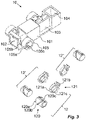
- the assembly 1 comprises a container holder 10 comprising a body 101 that defines an interior chamber 102 for receiving a medicament container.
- the body extends along a longitudinal axis L between a proximal end and a distal end.
- the shape of the interior chamber 102 may be dependent on a shape of the medicament container.
- the interior chamber 102 may be formed as correspondingly elongated, cylindrical or flat shaped respectively.
- the body 101 of the container holder 10 may be dependent on a shape of the medicament container as the interior chamber 102.
- the body 101 of the container holder 10 may be a shape that is different from the shape of the interior chamber 102; for example, the body 101 may be formed as a shape corresponding to the shape of an outer shell of a medicament delivery device that the assembly 1 can be included in said outer shell. Alternatively, the body 101 may be formed as a shape that is easy for a user to grip, so that the user may carry out a medicament delivery operation with the assembly 1.
- the body 101 of the container holder 10 may comprise a retaining portion 103 and a distal partition 104 (will be explained in detail later).
- the retaining portion 103 is configured to fix or to help to fix a medicament container that will be contained within the body 101 of the container holder 10.
- the retaining portion 103 is a part of the body 101 of the container holder 10.
- the retaining portion 103 may be designed as a shape corresponding with at least a part of a shape of the medicament container that will be contained within the interior chamber 102.
- the retaining portion 103 can be formed as a generally cylindrical shape; or if the medicament container comprises a flat portion, the retaining portion 103 can be formed with a diameter being narrower than a diameter of the rest of the interior chamber 102 of the container holder 10, so that the retaining portion 103 can snugly receive the flat portion of the medicament container.
- the retaining portion 103 may be configured to press-fit with the medicament container, or the retaining portion 103 may comprise a pair of flexible arms for snap fitting with the medicament container. Alternatively, the retaining portion 103 may function together with another component to clamp or fix the medicament container to the interior chamber 102 of the medicament delivery device.
- the assembly 1 comprises an actuator 11 having a body 111 extending along the longitudinal axis L between a first end and a second end, as shown in Fig. 1 .
- the actuator 11 is adjacent to the container holder 10 and movable relative to the container holder 10 along the longitudinal axis L.
- the actuator is rotationally fixed to the container holder; in a preferred example, the actuator is only movable relative to the container holder 10 along the longitudinal axis L.
- the actuator 11 comprises an activation surface 110 attached to the body 111 of the actuator 11.
- the activation surface 110 of the actuator is fixed to the body of the actuator 11.
- the activation surface of the actuator is an inclined surface angled relative to the longitudinal axis.
- the activation surface of the actuator is a protrusion protruding from a surface of the body of the actuator.
- the activation surface of the actuator 11 is a rack 110.
- the activation surface of the actuator can be arranged at one end of the body of the actuator, or arranged between the first end and the second end of the body of the actuator. The activation surface of the actuator will be explained in more detail later.
- the actuator 11 is configured to apply a force for initiating an operation of the assembly 1 and therefore initiating an operation of the medicament delivery device comprising the assembly 1.
- the body of the actuator 11 can be accessible to a user, so that the user may grip on or touch the actuator and manually move the actuator along the longitudinal axis L relative to the container holder 10; or the actuator may connect with a spring or a motor that moves the actuator along the longitudinal axis L once the spring or the motor has been released or initiated by the user.
- the body 111 of the actuator 11 comprises one or more arms; in a preferred embodiment, the actuator 11 comprises two arms 111a, 111b.
- the activation surface is arranged on the arm.
- the arm is configured to distribute the force applied on the actuator 11 in the direction of the longitudinal axis L.
- the arm may provide a large contact surface connecting to an energy source, e.g. a coil spring, a motor or a gas canister, so that a relatively large energy source (usually also with a relatively higher accumulated force) can be connected to the actuator; or being gripped or touched by a user's hand.
- the arm can allow a user to more easily grip and initiate the movement of the actuator.
- the arm 111a, 111b may be formed as two symmetrically arranged arms, so that the user can clamp the actuator between two fingers and initiate the assembly 1 with one hand.
- the body 111 of the actuator 11 comprises a tubular portion; the activation surface is arranged on an inner surface of the tubular portion of the body 111 of the actuator 11.
- the actuator 11 may comprise a join 111c connected between the arms 111a, 111b.
- the assembly 1 comprises one or more drive assemblies 12, 12', 12", depending on the design of the medicament delivery device.
- the assembly 1 comprises more than one drive assemblies 12, 12', 12"
- generally all of the drive assemblies are similar to one other, so only one drive assembly will be explained in detail, and such explanation regarding the drive assembly applies to any other drive assemblies if the assembly 1 comprises more than one drive assembly.
- the drive assembly 12 is attached to the body 101 of the container holder 10.
- the drive assembly may be configured to eject a medicament contained within a medicament container received within the interior chamber 102 of the container holder 10, or the drive assembly may be configured to clamp or fix the medicament container to the retaining portion 103 of the container holder 10.
- the drive assembly 12 comprises a motion converter and a rod 120 extending along a transverse axis T transverse to the longitudinal axis L.
- the rod 120 comprises a rod body 120a extending along the transverse axis T transverse to the longitudinal axis L.
- the motion converter of the drive assembly is configured to interact with the activation surface of the actuator 11 so that a movement of the actuator 11 in the direction of the longitudinal axis L relative to the container holder 10 will be converted into a movement of the rod 120 in the direction of the transverse axis T relative to the container holder 10 through the interaction between the activation surface and the motion converter.
- the rod 120 can therefore move into the interior chamber 102 of the container holder 10, or move out from the interior chamber 102 of the container holder 10 when the actuator moves relative to the container holder in the direction of the longitudinal axis L.
- the activation surface and the motion converter are configured to mechanically engage each other to perform the interaction between the activation surface and the motion converter.
- the motion converter of the drive assembly is connected to the rod 120, for example, the motion converter of the drive assembly can be attached to the rod body, or can be an integral part of the rod body.
- the activation surface of the actuator can be an inclined surface, a protrusion or a rack; the motion converter of the drive assembly is therefore formed correspondingly as will be explained with the following examples.
- the motion converter of the drive assembly can be an inclined surface or a protrusion transversely protruding relative to the longitudinal axis from the body 101 of the container holder 10.
- the motion converter of the drive assembly When the motion converter of the drive assembly is an inclined surface configured to contact with the inclined surface of the actuator, the inclined surface of the activation surface of the actuator is configured to face towards the inclined surface of the motion converter of the drive assembly.
- the inclined surface of the motion converter of the drive assembly is angled relative to the transverse axis T and the longitudinal axis; the inclined surface of the activation surface of the actuator is angled relative to the transverse axis T and the longitudinal axis L. Therefore, once the inclined surface of the motion converter of the drive assembly contacts with the inclined surface of the activation surface of the actuator, a movement of the actuator in the direction of the longitudinal axis L will push the motion converter of the drive assembly to move in the direction of the transverse axis T.
- the motion converter of the drive assembly is connected to the rod 120; so that a movement of the motion converter of the drive assembly in the direction of the transverse axis T causes the rod 120 to move along the transverse axis T.
- the motion converter of the drive assembly is a protrusion
- the protrusion is configured to contact with the inclined surface of the activation surface of the actuator.
- a movement of the actuator in the direction of the longitudinal axis L will push the motion converter of the drive assembly to move in the direction of the transverse axis T.
- the motion converter of the drive assembly is connected to the rod 120; so that a movement of the motion converter of the drive assembly in the direction of the transverse axis T causes the rod 120 to move along the transverse axis T.
- the motion converter of the drive assembly may comprise an inclined surface or a rotator.
- the activation surface of the actuator is a protrusion and the motion converter of the drive assembly comprises an inclined surface
- the inclined surface of the motion converter of the drive assembly is angled relative to the transverse axis T and the longitudinal axis L.
- the inclined surface of the drive assembly is configured to contact with the protrusion of the activation surface of the actuator.
- the rotator is configured to be rotatable around the transverse axis T relative to the body 101 of the container holder 10 and fixed to the body 101 of the container holder 10 in the direction of the transverse axis T.
- the rotator comprises a body and a guide track on a surface of the body.
- the guide track can be arranged on an outer surface of the body of the rotator.
- the protrusion of the activation surface of the actuator is configured to be positioned within or move into the guide track.
- the guide track can be formed by a ledge, a cut-out or a recess.
- the rotation of the rotator is configured to move the rod along the transverse axis T relative to the container holder, which arrangement will be explained in detail later.
- the activation surface of the actuator is a rack 110
- the motion converter of the drive assembly 12 can also be the rotator 121.
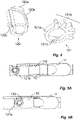
- the rotator 121 comprises teeth 121b extending outwardly relative to the transverse axis T from the outer surface of the body 121a of the rotator 121.
- the teeth 121b of the rotator 121 can be evenly distributed around the outer surface of the body 121a of the rotator 121; or only be distributed on a part of the outer surface of the body 121a of the rotator 121, as shown in Figs 3-4 .
- the rod 120 comprises a first engaging member 120b and a second engaging member 120c.
- the rotator comprises an engaging member 121c on a surface of the body 121a of the rotator 121.
- the first engaging member 120b of the rod 120 is configured to engage with the engaging member 121c of the rotator 121 thereby defining a first interface.
- the second engaging member 120c of the rod 120 is configured to engage with a counter engaging member of the body 101 of the container holder 10 thereby defining a second interface.
- One of the first interface and the second interface is a helical interface; and the other one of the first interface and the second interface is a spline interface so that when the rotator 121 rotates relative to the container holder around the transverse axis T, the rod will be moved along the transverse axis T relative to the container holder.
- the container holder 10 comprises a driving seat 105 for receiving the drive assembly 12.
- the driving seat 105 comprises a tubular body 105a, a cut-out 105b, and the counter engaging member 105c on the inner surface of the tubular body 105a.
- the tubular body 105a extends along the transverse axis T and the cut-out 105b extends circumferentially on the tubular body 150a.
- the body 121a of the rotator 121 is ring-shaped or tubular, and the engaging member 121c of the rotator 121 is arranged on an inner surface of the body 121a of the rotator 121.
- the rod 120 is arranged within the tubular body 105a of the driving seat 105, and the rotator 121 is arranged within the cut-out 105b of the driving seat 105.
- the container holder 10 can be arranged without the driving seat 105.
- the body of the container holder may comprise one or more openings, dependent on the numbers of the drive assemblies.
- the one or more openings open in the direction of the transverse axis T.
- the rotator of the drive assembly can be attached on the inner or outer surface of the body of the container holder; the rod of the drive assembly is configured to move through the one or more openings of the body of the container holder.
- the counter engaging member 105c can be arranged on an inner surface of the one or more openings.
- the container holder comprises two drive assemblies 12', 12" aligned parallel to one another on the body 101 of the container holder 10.
- the movement of the actuator 11 relative to the container holder 10 in the direction of the longitudinal axis L moves sequentially each rod of the two drive assemblies in the direction of the transverse axis T through the engagements between the two motion converters of the two drive assemblies and the activation surface of the actuator 11.
- the rack 110 of the activation surface of the actuator 11 aligns with teeth of the rotators of two drive assemblies 12', 12" in the direction of the longitudinal axis L.
- one of the two drive assemblies 12', 12" is configured to clamp or fix the medicament container to the interior chamber 102 of the container holder 10; and the other one of the two drive assemblies 12', 12" is configured to eject the contained medicament within the medicament container.
- both drive assemblies 12', 12" are configured to eject the contained medicament within the medicament container.
- the container holder 10 comprises two drive assemblies 12, 12' aligned with one another along the transverse axis T on the body 101 of the container holder 10.
- the actuator 11 comprises two activation surfaces; the movement of the actuator 11 relative to the container holder 10 in the direction of the longitudinal axis moves each rod of the two drive assemblies 12, 12' in the direction of the transverse axis T through the engagement between one motion converter of the two drive assemblies and one activation surface of the actuator 11 and the engagement between the other motion converter of the two drive assemblies and the other activation surface of the actuator 11.
- the two activation surfaces of the actuator 11 each comprise a rack.
- the two racks in the shown example are arranged between the first end of the body of the actuator 11 and the second end of the actuator 11; each tooth of the two racks extend in a direction perpendicular to the longitudinal axis and align respectively with teeth of rotators of the two drive assemblies 12, 12' in the direction of the longitudinal axis L.
- both drive assemblies 12, 12' are configured to eject the contained medicament within the medicament container.
- the teeth 121b of the rotator 121 is configured to mesh with the rack 110 of the activation surface of the actuator 11.
- the teeth 121b of the rotator 121 are aligned with the rack 110 of the activation surface of the actuator 11 in the direction of the longitudinal axis L.
- the rotator 121 is axially fixed to the body 101 of the container holder 10 in the direction of the transverse axis T and the longitudinal axis L.
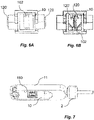
- the rotator 121 is fixed to the body 101 of the container holder 10 in the direction of the longitudinal axis L, so that the axial movement of the actuator 11 along the longitudinal axis L rotates the rotator 121 around the transverse axis T, due to the mesh between the teeth 121b of the rotator 121 and the rack 110 of the activation surface of the actuator 11, as shown in Figs 5A-5B .
- the rotator may be movable relative to the body of the container holder in the direction of the longitudinal axis L.
- the drive assembly may be movable relative to the container holder in the direction of the longitudinal axis L.
- the rotator is movable also relative to the actuator 11. Therefore, the relative axial movement along the longitudinal axis between the rotator and the actuator rotates the rotator around the transverse axis T, due to the mesh between the teeth 121b of the rotator 121 and the rack 110 of the activation surface of the actuator 11.
- the rotation of the rotator 121 around the transverse axis T is configured to move the rod 120 in the direction of the transverse axis T relative to the body 101 of the container holder 10.
- This movement of the rod 120 that is initiated by the rotation of the rotator 121 is caused by an arrangement in which one of the first interface and the second interface is a helical interface; the other one of the first interface and the second interface is a spline interface as mentioned above.
- the first interface is a helical interface.
- the first engaging member 120b of the rod 120 is a helical thread or a protrusion.
- the engaging member 121c of the rotator 121 is a helical thread when the first engaging member 120b of the rod 120 is a protrusion, or a protrusion when the first engaging member 120b of the rod 120 is a helical thread.
- the first engaging member 120b of the rod 120 is the helical thread; and the engaging member 121c of the rotator 121 is the protrusion.
- the second interface is a spline interface, namely, the second engaging member 120c of the rod 120 is a slot or a rib; and the counter engaging member 105c arranged on the body 101 of the container holder 10 is a slot when the second engaging member 120c of the rod 120 is a rib; or a rib when second engaging member 120c of the rod 120 is a slot or a rib.
- the second engaging member 120c of the rod 120 is the slot; and the counter engaging member 105c arranged on the body 101 of the container holder 10 is the rib.
- the rod 120 can be transversely aligned with a ridge portion of the medicament container, or a portion of the medicament container that is not enclosing the contained medicament.
- the rod 120 can therefore clamp the medicament container between the rod 120 and the inner surface of the retaining portion 103.
- the rod 120 is configured to act on the collapsible medicament container within the interior chamber 102 of the container holder 10.
- the rod 120 therefore, can squeeze the medicament contained within the collapsible medicament container out between the rod 120 and the inner surface of the body 101 of the container holder 10 or between two rods 120, 120' as shown in Fig. 6B in the example that the assembly 1 comprises a two or more drive assemblies.
- the assembly may be designed as a disposable assembly or a reusable assembly.
- the activation surface of the actuator is configured to fully disconnected with the motion converter of the drive assembly.
- the rack of the activation surface of the actuator can be fully disengaged and misaligned with the teeth of the rotator of the motion converter of the drive assembly when the actuator moves along the longitudinal axis L relative to the container holder with a predetermined distance. Once the actuator axially moves along the longitudinal axis L relative to the container holder with the predetermined distance, any further movement of the actuator relative to the container holder along the longitudinal axis L cannot be transferred to the drive assembly.
- the activation surface of the actuator is configured to connect with the motion converter of the drive assembly all the time. Therefore, the movement of the actuator 11 relative to the container holder 10 along the longitudinal axis L in one direction may cause the rod 120 moves into the interior chamber 102 of the container holder 10. Therefore, the rod 120 can clamp or squeeze the contained medicament container. Any further or reverse movement of the actuator 11 relative to the container holder 10 along the longitudinal axis L may cause the rod 120 to move out from the interior chamber 102 of the container holder 10. As a result, the rod 120 can disengage with the contained medicament container.
- the assembly 1 is reusable.
- the assembly 1 comprises three drive assemblies 12, 12', 12", as shown in Fig. 3 .
- One of the three drive assemblies 12, 12', 12" is configured to clamp a portion of a collapsible medicament container, and the other two of the three drive assemblies 12, 12', 12" are configured to eject the medicament contained within the medicament container.
- the two of the three drive assemblies 12, 12', 12" for ejecting the medicament contained within the medicament container are symmetrically arranged on two sides of the body 101 of the container holder 10; the rod of each drive assembly 12, 12', 12" is facing towards other rods along the transverse axis T.
- the rods of the two drive assemblies are coaxial to each other in the direction of the transverse axis T.
- the assembly 1 may comprise a motor 2, e.g. step motor, connected to the actuator 11, as shown in Fig. 7 .
- the assembly 1 may comprise a switch 3 connected with an electronics set E, as shown in Fig. 8 .
- the electronics set E may comprise any one of a processor, a wireless communication receiver/ transmitter, a vibration motor, a buzzer, a memory, an NFC/ RFID circuit, a sensor, a timer, or any combination thereof.
- the switch 3 and the electronics set E are arranged within the distal partition 104 of the container holder 10.
- the switch 3 is movable relative to the electronics set E and/ or the body 101 of the container holder 10 between an open position and a closed position.
- the assembly 1 may be designed that the motor 2 will therefore be activated and initiate the movement of the actuator 11 relative to the body 101 of the container holder 10; alternatively, an operation from the electronics set E may be triggered.
- the switch may be pivotable relative to the electronics set E and/ or the body of the container holder between the open position and the closed position.
- the switch 3 is linearly movable relative to the electronics set E and/ or the body of the container holder between the open position and the closed position along a linear path, in a direction of the longitudinal axis L, or in a direction perpendicular to the longitudinal axis L.
- the switch may be accessible to the user; that is, the user may directly contact and manually move the switch between the open position and the closed position.
- the switch may be inaccessible to the user; that is, the user cannot directly contact or move the switch between the open position and the closed position and instead the switch is moved by a component of the medicament delivery device comprising the assembly 1.
- the switch 3 may be moved by the medicament container received within the interior chamber 102 of the container holder 10.
- the distal partition 104 may be formed by a distal wall 104a and a ledge 104b.
- the electronics set E and the switch 3 are received between the distal wall 104a and the ledge 104b.
- the switch 3 is attached to the electronics set E, as shown in Fig. 8 .
- the ledge 104b of the distal partition comprises a cut-out 104c. A shape of the cut-out is dependent on the shape of at least a portion of the medicament container, and a direction for loading the medicament container into the interior chamber 102 of the container holder 10.
- the medicament container may be loaded into the interior chamber 102 of the container holder 10 by moving along the longitudinal axis L from the proximal end of the container holder 10.
- the cut-out 104c is in a direction of longitudinal axis L; the cut-out 104c is formed as a corresponding shape to a distal portion of the medicament container so that the distal portion of the medicament container can pass through the cut-out 104c.
- the distal portion of the medicament container moves past the cut-out 104c, and presses on the electronics set E in the distal direction.
- the switch 3 is moved toward the distal wall 104a of the distal partition 104.
- a reaction force between the distal wall 104a of the distal partition 104 moves the switch 3 from the open position to the closed position.
- the assembly 1 optionally comprises a biasing member 4; in one example, the biasing member 4 can be a compression coil spring.
- the biasing member 4 can be used when the switch 3 is linearly movable relative to the electronics set E and/or the body 101 of the container holder 10.
- the biasing member 4 is compressible between a relaxed position and a compressed position along the linear path of the switch 3.
- the biasing member 4 at least partially surrounds the switch 3; a linear moving distance between the relaxed position of the biasing member 4 and the compressed position of the biasing member 4 is longer than a linear moving distance between the open position of the switch and the closed position of the switch 3. The switch 3, therefore, cannot be moved into the closed position from the open position without first moving the biasing member 4 into the compressed position.
- the biasing member 4 therefore, can be a security mechanism to avoid unintentionally initiating the actuator 11 or any other unintentional operation of the electronics set E due to any accidental contact with the switch 3.
- some of the medicament containers comprise a preassembled delivery member, e.g. a needle, attached to the medicament container without a fluid connection with the contained medicament before use.
- a preassembled delivery member e.g. a needle
- Some of those medicament containers require the user to establish the fluid connection between the delivery member and the contained medicament, for example by pushing the medicament delivery member towards the contained medicament.
- the assembly 1 is used with those medicament containers, the user needs to push the delivery member to establish the fluid connection between the delivery member and the contained medicament.
- the biasing member 4 can therefore be another type of security mechanism to make sure the user has properly established the fluid connection between the delivery member and the contained medicament before using the assembly 1 for delivering the contained medicament.
- the linear moving path of the switch 3 is aligned with a moving path of the delivery member, namely the moving path that the user linearly moves the delivery member to establish the fluid connection between the delivery member and the contained medicament.
- the biasing member 4 may be chosen with a force greater than a force needed to establish the fluid connection between the delivery member and the contained medicament.
- the delivery member may be snapped onto the medicament container for establishing the fluid connection between the delivery member and the contained medicament by at least 4N pushing force; in this example, the assembly 1 may comprise the biasing member 4 with a certain elastic potential energy so that the biasing member 4 can be moved into the compressed position by at least 5N force.
- the assembly 1 is configured to have a medicament container loaded into the interior chamber 102 of the container holder 10 by inserting the medicament container from the proximal end of the container holder 10.
- the body 101 of the container holder 10 is dimensioned to fully cover the medicament container except for a front cap (usually for covering the preassembled delivery member).
- a front cap usually for covering the preassembled delivery member.
- the assembly 1 is used with a medicament delivery device with an outer shell (as shown in Fig. 11 ), then the body 101 of the container holder 10 doesn't need to fully cover the medicament container. The user will be instructed to push on the preassembled delivery member through the front cap to load the medicament container into the interior chamber 102 of the container holder 10.
- the switch 3, the biasing member 4 and the electronics set E are all arranged between the distal wall 104a and the ledge 104b of the distal partition 104.
- the biasing member 4 member is a compression coil spring; and the switch is surrounded by the compression coil spring 4, as shown in Fig. 9 .
- the biasing member 4 is positioned along the longitudinal axis L between the electronics set E and the distal wall 104a of the distal partition 104.
- the distal portion of the medicament container M protrudes into the distal partition 104 and pushes on the electronics set E.
- the switch 3 can be moved into the closed position by the reaction force between the distal wall 104a and the switch 3.
- Fig. 11 illustrates a medicament delivery device 5 comprising the assembly 1.
- the medicament delivery device 5 comprises the outer shell 50 extending along the longitudinal axis L between a proximal end and a distal end.
- the outer shell 50 is configured to accommodate the container holder 10.
- the container holder 10, the actuator 11 and a power source, e.g. a motor or a spring, are all fully arranged within the outer shell 50, as shown in Fig. 13 .
- the container holder is arranged within the outer shell; and the actuator is partially arranged within the outer shell 50, so that the user can manually move the actuator relative to the outer shell 50 along the longitudinal axis L.
- the container holder can be fixed to the outer shell, or axially movable in the direction of the longitudinal axis L relative to the outer shell.
- the medicament delivery device 5 may comprise a user interface 51 providing indications/ instructions to the user, through one or more texture, mark, light, sound and/ or vibration.
- the user interface 51 can be an LCD display or E-Ink, for example; the user interface 51 may connect with the electronics set E, the switch 3 and/ or the motor 2 of the assembly.
- the user interface 51 may be a touch panel with which the user can input data or trigger one or more operations of the medicament delivery device 5 .
- the user interface 51 may be configured to be activated by moving the switch 3 into the closed position, and the motor may be configured to be controlled by the user input from the user interface 51.
- the user interface 51 can be a transparent window aligned with the medicament container for the user to observe the contained medicament.
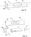
- the medicament delivery device 5 comprises a delivery member guard 6, as shown in Fig. 12 .
- the delivery member guard 6 comprises a tubular body 60 with a contact portion 60a for contacting the medicament delivery site and a central passage 60b for accommodating the medicament delivery member connected to the medicament container.
- the delivery member guard 6 is attached to the outer shell 50 and axially movable relative to the outer shell 50 in the direction of the longitudinal axis L between an extended position, as shown in Fig. 12 , and a retracted position, as shown in Fig. 11 .
- the delivery member guard is optionally connected to a guard biasing member.
- the guard biasing member can be a spring or a flexible arm arranged between an inner surface of the outer shell and the delivery member guard 6.
- the guard biasing member is configured to bias the delivery member guard to the extended position.
- the delivery member guard 6 is configured to be moved to the extended position from the retracted position by the user manually pulling on the contact portion 60a of the delivery member guard 6.
- the outer shell 50 of the medicament delivery device 5 comprises a concave portion 52 arranged on the proximal edge of the outer shell and facing towards the proximal end of the medicament delivery device 5. Therefore, the user can grip on the contact portion 60a through the concave portion 52 of the outer shell 50 for pulling the delivery member guard 6 to the extended position.
- the medicament delivery device 5 comprises the assembly 1 with the motor 2 for moving the actuator along the longitudinal axis L relative to the container holder 10.
- the delivery member guard 6 in the presented example comprises the tubular body 60 and two symmetrically arranged buttons 61a, 61b arranged on an outer surface of the guard body 60 and facing towards one another.
- the two buttons 61a, 61b are movable relative to the tubular body 60 and the outer shell in the direction of the transverse axis T.
- the two buttons 61a, 61b are movable relative to the tubular body 60 and the outer shell 50 between a relaxed position and a pressed position where the two buttons 61a, 61b are closer to each other in the direction of the transverse axis T than in the relaxed position, as shown in Fig. 14A-14B .
- the delivery member guard 6 further comprises two biasing elements 62a, 62b.
- the two biasing elements 62a, 62b are two compression coil springs.
- the two biasing elements 62a, 62b are arranged between inner surfaces of the two buttons 61a, 61b respectively and corresponding surfaces of the guard body 60.
- the two biasing elements 62a, 62b are configured to push the two buttons 61a, 61b respectively in the direction of the transverse axis T from the pressed position to the relaxed position.
- each of the two buttons 61a, 61b comprises a blade 611a, 611b fixed to the button.
- Each blade 611a, 611b extends in the direction of the transverse axis T and faces to each other.
- the two blades 611a, 611b are moved towards one another together with the two buttons.
- the two blades 611a, 611b therefore, move further into the central passage 60b of the delivery member guard 6.
- the user may press the two buttons into the pressed position so that the blades 611a, 611b can cut the medicament delivery member received within the central passage 60b of the delivery member guard 6.
- the blades 611a, 611b may be configured to contact with each other, or overlap to each other in the longitudinal axis, or move close to each other without contact when the two buttons 61a, 61b are in the pressed position, dependent on a dimension of the medicament delivery member received within the central passage 60b of the delivery member guard 6.
- the outer shell 50 of the medicament delivery device 5 comprises an inner proximal portion 53 for receiving the two buttons 61a, 61b when the delivery member guard 6 is in the retracted position.
- the two buttons 61a, 61b protrude transversely from the outer shell 50 (as highlighted by a dashed line in Fig. 15A ) when the two buttons in the relaxed position. Therefore, when the two buttons 61a, 61b are received within the inner proximal portion 53 of the outer shell 50, the two buttons 61a, 61b will press on inner surfaces of the outer shell 50 due to the force from the two biasing elements 62a, 62b.
- the delivery member guard 6 is, therefore, press fitting to the outer shell 50 in the retracted position, as shown in Fig. 15B .
- the two buttons 61a, 61b move to the relaxed position.
- distal edges of the two buttons 61a, 61b abut the proximal edge of the outer shell, therefore, the delivery member guard 6 cannot move to the retracted position unless the two buttons 61a, 61b are pressed.
- a longitudinal length of the two buttons 61a, 61 b can therefore determine a user-accessible portion of the delivery member.
- the user-accessible portion of the delivery member should be the portion that is not covered by the tubular body 60 of the delivery member guard 6.
- the user-accessible portion of the needle is usually equal to an injection depth (since the user-accessible portion of the needle can be fully inserted into an injection site), so the longitudinal length of the two buttons 61a, 61 b can therefore be used to fix the injection depth.
Landscapes
- Health & Medical Sciences (AREA)
- Vascular Medicine (AREA)
- Engineering & Computer Science (AREA)
- Anesthesiology (AREA)
- Biomedical Technology (AREA)
- Heart & Thoracic Surgery (AREA)
- Hematology (AREA)
- Life Sciences & Earth Sciences (AREA)
- Animal Behavior & Ethology (AREA)
- General Health & Medical Sciences (AREA)
- Public Health (AREA)
- Veterinary Medicine (AREA)
- Infusion, Injection, And Reservoir Apparatuses (AREA)
Abstract
Description
- The present disclosure generally relates to an assembly for a medicament delivery device and particularly to an assembly with a drive assembly comprising a rod and a motion converter.
- Medicament delivery devices such as pen-type injectors or safety syringes are generally known for the self-administration of a medicament by patients without formal medical training. As just one example, those patients suffering from diabetes may require repeated injections of insulin. Other patients may require regular injections of other types of medicaments, such as a growth hormone.
- To help patients perform the self-administration of a medicament, medicament delivery devices are usually designed with one or more assemblies or subassemblies providing automatic functions, force transferring functions, and/ or manipulation guide functions. The medicament can therefore be prepared properly, applied with a proper force and/or be delivered within a proper time period without any complicated manipulation by patients.
- The invention is defined by the appended claims, to which reference should now be made.
- In the present disclosure, when the term "distal direction" is used, this refers to the direction pointing away from the dose delivery site during use of the medicament delivery device. When the term "distal part/end" is used, this refers to the part/end of the delivery device, or the parts/ends of the members thereof, which under use of the medicament delivery device is/are located furthest away from the dose delivery site. Correspondingly, when the term "proximal direction" is used, this refers to the direction pointing towards the dose delivery site during use of the medicament delivery device. When the term "proximal part/end" is used, this refers to the part/end of the delivery device, or the parts/ends of the members thereof, which under use of the medicament delivery device is/are located closest to the dose delivery site.
- Further, the terms "longitudinal" and "longitudinally" refer to a direction extending from the proximal end to the distal end, typically along with the device or components thereof in the direction of the longest extension of the device and/or component.
- Similarly, the terms "transverse", "transversal" and "transversally" refer to a direction generally perpendicular to the longitudinal direction.
- Further, the terms "circumference", "circumferential", "circumferentially", "radial", "radially", "rotation", "rotational" and "rotationally" refer to a direction generally perpendicular to the longitudinal direction and at least partially extending around the longitudinal direction.
- There is hence provided an assembly for a medicament delivery device, the assembly comprising: a container holder comprising a body extending along a longitudinal axis between a proximal and a distal end, the body defining an interior chamber for receiving a medicament container; an actuator connected to the container holder and axially movable relative to the body of the container holder; and a drive assembly attached to the body of the container holder; wherein the drive assembly comprises a motion converter and a rod; wherein the actuator comprises an activation surface movable relative to the motion converter of the drive assembly in the direction of the longitudinal axis; and wherein a movement of the actuator relative to the container holder in the direction of the longitudinal axis is converted to a movement of the rod relative to the container holder along a transverse axis transverse to the longitudinal axis through an engagement between the motion converter of the drive assembly and the activation surface of the actuator.
- According to one embodiment, the motion converter of the drive assembly is attached to the rod.
- According to one embodiment, the motion converter of the drive assembly comprises an inclined surface angled to the transverse axis and the longitudinal axis.
- According to one embodiment, the activation surface of the actuator comprises an inclined surface angled relative to the transverse axis and the longitudinal axis.
- According to one embodiment, the inclined surface of the motion converter of the drive assembly is configured to face towards the inclined surface of the activation surface of the actuator.
- According to one embodiment, the motion converter of the drive assembly comprises a protrusion extending from the body of the container holder in the direction of the transverse axis.
- According to one embodiment, the motion converter of the drive assembly comprises a rotator fixed to the body of the container holder in the direction of the transverse axis and rotatable around the transverse axis relative to the body of the container holder; and the rotator comprises a body comprising an outer surface.
- According to one embodiment, the activation surface of the actuator comprises a protrusion.
- According to one embodiment, the protrusion of the activation surface of the actuator extends in the direction of the longitudinal axis.
- According to one embodiment, the rotator comprises a guide track on the outer surface of the body of the rotator; the protrusion of the activation surface of the actuator extends in a direction perpendicular to the longitudinal axis; and the protrusion of the activation surface of the actuator follows the track of the rotator when the actuator moves relative to the rotator in the direction of the longitudinal axis.
- According to one embodiment, the rotator comprises teeth extending outwardly relative to the transverse axis from the outer surface of the body of the rotator; the activation surface of the actuator comprises a rack; each tooth of the rack extends in a direction perpendicular to the longitudinal axis; and the rack aligns with the teeth of the rotator in the direction of the longitudinal axis.
- According to one embodiment, the rotator comprises an engaging member on a surface of the body of the rotator; the rod comprises a first engaging member engaged with the engaging member of the rotator thereby defining a first interface; the rod comprises a second engaging member engaged with a counter engaging member of the body of the container holder thereby defining a second interface; and one of the first interface and the second interface is a helical interface; and the other one of the first interface and the second interface is a spline interface.
- According to one embodiment, the first interface is a helical interface.
- According to one embodiment, the first engaging member of the rod is a helical thread; and the engaging member of the rotator is a protrusion.
- According to one embodiment, the first engaging member of the rod is a protrusion; and the engaging member of the rotator is a helical thread.
- According to one embodiment, the second engaging member of the rod is a rib.
- According to one embodiment, the second engaging member of the rod is a slot.
- According to one embodiment, the counter engaging member arranged on the body of the container holder is a rib.
- According to one embodiment, the counter engaging member arranged on the body of the container holder is a slot.
- According to one embodiment, the second interface is a helical engagement.
- According to one embodiment, the second engaging member of the rod is a helical thread; and the counter engaging member of the body of the container holder is a protrusion.
- According to one embodiment, the second engaging member of the rod is a protrusion; and the counter engaging member of the body of the container holder is a helical thread.
- According to one embodiment, the first engaging member of the rod is a rib.
- According to one embodiment, the first engaging member of the rod is a slot.
- According to one embodiment, the engaging member of the rotator is a rib.
- According to one embodiment, the engaging member of the rotator is a slot.
- According to one embodiment, the body of the rotator is ring-shaped or tubular.
- According to one embodiment, the engaging member of the rotator is arranged on an inner surface of the body of the rotator.
- According to one embodiment, the rod comprises a rod body extending along the transverse axis
- According to one embodiment, the body of the rotator at least partially encloses the rod body; and the first engaging member of the rod is arranged on an outer surface of the rod body.
- According to one embodiment, the engaging member of the rotator is arranged on the outer surface of the body of the rotator.
- According to one embodiment, the rod body comprises a tubular portion at least partially enclosing the body of the rotator; and the first engaging member of the rod is arranged on an inner surface of the tubular portion of the rod body.
- According to one embodiment, the second engaging member of the rod is arranged on an outer surface of the rod body.
- According to one embodiment, the rod body comprises a tubular portion; and wherein the second engaging member of the rod is arranged on an inner surface of the tubular portion of the rod body.
- According to one embodiment, the assembly comprises two drive assemblies aligned parallel to one another on the body of the container holder; the movement of the actuator relative to the container holder in the direction of the longitudinal axis is configured to move sequentially each rod of the two drive assemblies along the transverse axis through the engagements between the two motion converters of the two drive assemblies and the activation surface of the actuator.
- According to one embodiment, the assembly comprises two drive assemblies aligned coaxially to one another in the direction of the transverse axis on the body of the container holder; the actuator comprises two activation surfaces; the movement of the actuator relative to the container holder in the direction of the longitudinal axis moves each rod of the two drive assemblies in the direction of the transverse axis through the engagement between one motion converter of the two drive assemblies and one activation surface of the actuator; and the engagement between the other one motion converter of the two drive assemblies and the other one activation surface of the actuator.
- According to one embodiment, the rotator is fixed to the body of the container holder in the direction of the longitudinal axis.
- According to one embodiment, the assembly comprises a motor connected to the actuator and a switch attached to the container holder; the switch is movable relative to the body of the container holder between an open position and a closed position where the motor is configured to initiate the movement of the actuator relative to the body of the container holder.
- According to one embodiment, the switch is movable relative to the body of the container holder between the open position and the closed position along a linear path.
- According to one embodiment, the assembly comprises a biasing member being compressible between a relaxed position and a compressed position along the linear path of the switch; the biasing member at least partially surrounds the switch; and a linear moving distance between the relaxed position of the biasing member and the compressed position of the biasing member is longer than a linear moving distance between the open position of the switch and the closed position of the switch.
- According to one embodiment, the biasing member is a compression coil spring; and the switch is surrounded by the compression coil spring.
- According to one embodiment, the linear path of the switch is in the direction of the longitudinal axis
- According to one embodiment, the assembly can be operated by a method comprising the steps of: placing a medicament container within the interior chamber of the container holder; moving the actuator along the longitudinal axis relative to the body of the medicament container; moving the rod along the transverse axis relative to the body of the medicament container upon moving the actuator.
- According to one embodiment, the step of placing a medicament container within the interior chamber of the container holder further comprises the steps of: inserting the medicament container from the proximal end of the body of the container holder; and moving the medicament container axially along the longitudinal axis towards the distal end of the body of the container holder.
- According to one embodiment, the method comprises the step of: moving the switch from the open position to the closed position upon placing a medicament container within the interior chamber of the container holder.
- According to one embodiment, the method comprises the step of: compressing the biasing member from the relaxed position to the compressed position upon placing a medicament container within the interior chamber of the container holder; and moving the switch from the open position to the closed position.
- According to one embodiment, the assembly can be used in a medicament delivery device.
- According to one embodiment, the medicament delivery device that comprises the assembly can be an auto-injector, a pen injector, an inhalation device, or a medical sprayer.
- According to one embodiment, the medicament delivery device comprises a collapsible medicament container.
- According to one embodiment, the collapsible medicament container is configured to connect to a preassembled medicament delivery member.
- According to one embodiment, a fluid connection between the preassembled medicament delivery member and a medicament contained within the collapsible medicament container is configured to be established by a user who will start a medicament delivery operation shortly.
- According to one embodiment, the medicament delivery member can be an injection needle, a cannula or a spray nozzle.
- According to one embodiment, the medicament delivery device comprises an outer shell extending along the longitudinal axis between a proximal end and a distal end; the container holder is arranged within the outer shell.
- According to one embodiment, the actuator is arranged within the outer shell.
- According to one embodiment, the medicament delivery device comprises a delivery member guard at least partially arranged within the outer shell; the delivery member guard comprises a tubular body defining a central passage extending along the longitudinal axis, the tubular body is for surrounding a delivery member connected to the medicament container.
- According to one embodiment, the delivery member guard comprises two buttons arranged on the tubular body of the delivery member guard and aligned coaxially to one another in the direction of the transverse axis; two buttons are movable relative to the outer shell in the direction of the transverse axis between a relaxed position and a pressed position where the two buttons are closer to each other in the direction of the transverse axis in the pressed position than in the relaxed position.
- According to one embodiment, the delivery member guard comprises two biasing elements respectively arranged between each button and the tubular body of the delivery member guard; and the biasing elements are compressible in the direction of the transverse axis between the relaxed position of the two buttons and the pressed position of the two buttons.
- According to one embodiment, the biasing elements are compression coil springs.
- According to one embodiment, the biasing elements are tension coil springs.
- According to one embodiment, the biasing elements are bend springs.
- According to one embodiment, the delivery member guard is movable along the longitudinal axis relative to the outer shell between an extended position where the two buttons protrude completely from the proximal end of the outer shell in the direction of the longitudinal axis and a retracted position where the two buttons at least partially received within a proximal portion of the outer shell.
- According to one embodiment, a transversely linear distance between the two buttons when the two buttons are in the relaxed position defines a first length; a transversely linear distance between two buttons when the two buttons are in the pressed position defines a second length; and a transversely measured length of the proximal portion of the outer shell is smaller than the first length and greater than the second length.
- According to one embodiment of the invention, that provides an assembly for a medicament delivery device comprising: a container holder comprising a body extending along a longitudinal axis between a proximal end and a distal end, the body defining an interior chamber for receiving a medicament container; an actuator movable in the direction of the longitudinal axis relative the body of the container holder; a drive assembly attached to the body of the container holder; the drive assembly comprises a motion converter and a rod movable along a transverse axis transverse to the longitudinal axis relative to the body of the container holder; and the actuator comprises an activation surface configured to interact with the motion converter of the drive assembly when the actuator moves relative to the container holder in the direction of the longitudinal axis so that the rod is moved along the transverse axis.
- According to one embodiment of the invention, that provides a method of operating an assembly for a medicament delivery device, the assembly comprising a container holder comprising a body for receiving a medicament container; an actuator movable along a longitudinal axis relative to the body of the container holder; and a drive assembly attached to the body of the container holder; wherein the drive assembly comprises a transversely movable rod and a motion converter; the method comprising the steps of: placing a medicament container within the body of the container holder; moving the actuator along the longitudinal axis relative to the body of the medicament container; moving the rod along the transverse axis relative to the body of the medicament container upon moving the actuator.
- Generally, all terms used in the claims are to be interpreted according to their ordinary meaning in the technical field, unless explicitly defined otherwise herein. All references to "a/an/the element, apparatus, component, means, etc." are to be interpreted openly as referring to at least one instance of the element, apparatus, component, means, etc., unless explicitly stated otherwise.
- Embodiments of the inventive concept will now be described, by way of example only, with reference to the accompanying drawings, in which:
-
Fig 1 schematically shows a perspective view of an assembly for a medicament delivery device. -
Fig. 2 schematically shows a perspective view of parts of components of the assembly ofFig.1 . -
Fig. 3 schematically shows a perspective view of a container holder and a drive assembly of the assembly ofFig.1 . -
Fig. 4 schematically shows a perspective view of the drive assembly ofFig. 3 . -
Figs 5A-5B schematically show side views of the assembly ofFig.1 . -
Figs 6A-6B schematically show front views of the assembly ofFig.1 in the positions ofFigs 5A-5B . -
Fig. 7 schematically shows a perspective view of the assembly ofFig.1 with a motor. -
Fig. 8 schematically shows a perspective view of the container holder ofFig. 3 with an electronics set and a biasing member. -
Fig. 9 schematically shows a top view of the container holder ofFig. 8 with the electronics set and the biasing member ofFig. 8 . -
Fig. 10 schematically shows a top view of the container holder ofFig. 9 with a medicament container. -
Fig. 11 schematically shows a perspective view of a medicament delivery device. -
Fig. 12 schematically shows a perspective view of the medicament delivery device ofFig. 11 . -
Fig. 13 schematically shows a perspective view of components of the medicament delivery device ofFig. 11 . -
Figs 14A-B schematically show side views of the medicament delivery device ofFig. 11 . -
Figs 15A-B schematically show side views of a proximal portion of the medicament delivery device ofFig. 11 . -
Figs 1-10B illustrate anassembly 1 for a medicament delivery device. Theassembly 1 comprises acontainer holder 10 comprising abody 101 that defines aninterior chamber 102 for receiving a medicament container. The body extends along a longitudinal axis L between a proximal end and a distal end. The shape of theinterior chamber 102 may be dependent on a shape of the medicament container. For example, when the medicament container is elongated, cylindrical or flat, theinterior chamber 102 may be formed as correspondingly elongated, cylindrical or flat shaped respectively. Similarly, thebody 101 of thecontainer holder 10 may be dependent on a shape of the medicament container as theinterior chamber 102. On the other hand, thebody 101 of thecontainer holder 10 may be a shape that is different from the shape of theinterior chamber 102; for example, thebody 101 may be formed as a shape corresponding to the shape of an outer shell of a medicament delivery device that theassembly 1 can be included in said outer shell. Alternatively, thebody 101 may be formed as a shape that is easy for a user to grip, so that the user may carry out a medicament delivery operation with theassembly 1. - As shown in
Fig. 2 , thebody 101 of thecontainer holder 10 may comprise a retainingportion 103 and a distal partition 104 (will be explained in detail later). The retainingportion 103 is configured to fix or to help to fix a medicament container that will be contained within thebody 101 of thecontainer holder 10. In a preferred example, the retainingportion 103 is a part of thebody 101 of thecontainer holder 10. The retainingportion 103 may be designed as a shape corresponding with at least a part of a shape of the medicament container that will be contained within theinterior chamber 102. For example, if the medicament container is formed as generally cylindrical shape, the retainingportion 103 can be formed as a generally cylindrical shape; or if the medicament container comprises a flat portion, the retainingportion 103 can be formed with a diameter being narrower than a diameter of the rest of theinterior chamber 102 of thecontainer holder 10, so that the retainingportion 103 can snugly receive the flat portion of the medicament container. - The retaining
portion 103 may be configured to press-fit with the medicament container, or the retainingportion 103 may comprise a pair of flexible arms for snap fitting with the medicament container. Alternatively, the retainingportion 103 may function together with another component to clamp or fix the medicament container to theinterior chamber 102 of the medicament delivery device. - The
assembly 1 comprises anactuator 11 having abody 111 extending along the longitudinal axis L between a first end and a second end, as shown inFig. 1 . Theactuator 11 is adjacent to thecontainer holder 10 and movable relative to thecontainer holder 10 along the longitudinal axis L. The actuator is rotationally fixed to the container holder; in a preferred example, the actuator is only movable relative to thecontainer holder 10 along the longitudinal axis L. - The
actuator 11 comprises anactivation surface 110 attached to thebody 111 of theactuator 11. Theactivation surface 110 of the actuator is fixed to the body of theactuator 11. - In one example, the activation surface of the actuator is an inclined surface angled relative to the longitudinal axis. In another example, the activation surface of the actuator is a protrusion protruding from a surface of the body of the actuator. In another example, the activation surface of the
actuator 11 is arack 110. The activation surface of the actuator can be arranged at one end of the body of the actuator, or arranged between the first end and the second end of the body of the actuator. The activation surface of the actuator will be explained in more detail later. - The
actuator 11 is configured to apply a force for initiating an operation of theassembly 1 and therefore initiating an operation of the medicament delivery device comprising theassembly 1. For example, the body of theactuator 11 can be accessible to a user, so that the user may grip on or touch the actuator and manually move the actuator along the longitudinal axis L relative to thecontainer holder 10; or the actuator may connect with a spring or a motor that moves the actuator along the longitudinal axis L once the spring or the motor has been released or initiated by the user. - In one example, the
body 111 of theactuator 11 comprises one or more arms; in a preferred embodiment, theactuator 11 comprises twoarms actuator 11 in the direction of the longitudinal axis L. For example, the arm may provide a large contact surface connecting to an energy source, e.g. a coil spring, a motor or a gas canister, so that a relatively large energy source (usually also with a relatively higher accumulated force) can be connected to the actuator; or being gripped or touched by a user's hand. Alternatively, the arm can allow a user to more easily grip and initiate the movement of the actuator. For example, thearm assembly 1 with one hand. In another example, thebody 111 of theactuator 11 comprises a tubular portion; the activation surface is arranged on an inner surface of the tubular portion of thebody 111 of theactuator 11. - In a preferred example, if the
actuator 11 comprises more than onearm actuator 11 may comprise ajoin 111c connected between thearms - The
assembly 1 comprises one ormore drive assemblies assembly 1 comprises more than onedrive assemblies assembly 1 comprises more than one drive assembly. - The
drive assembly 12 is attached to thebody 101 of thecontainer holder 10. The drive assembly may be configured to eject a medicament contained within a medicament container received within theinterior chamber 102 of thecontainer holder 10, or the drive assembly may be configured to clamp or fix the medicament container to the retainingportion 103 of thecontainer holder 10. - The
drive assembly 12 comprises a motion converter and arod 120 extending along a transverse axis T transverse to the longitudinal axis L. Preferably, therod 120 comprises arod body 120a extending along the transverse axis T transverse to the longitudinal axis L. The motion converter of the drive assembly is configured to interact with the activation surface of theactuator 11 so that a movement of theactuator 11 in the direction of the longitudinal axis L relative to thecontainer holder 10 will be converted into a movement of therod 120 in the direction of the transverse axis T relative to thecontainer holder 10 through the interaction between the activation surface and the motion converter. Therod 120 can therefore move into theinterior chamber 102 of thecontainer holder 10, or move out from theinterior chamber 102 of thecontainer holder 10 when the actuator moves relative to the container holder in the direction of the longitudinal axis L. - In a preferred example, the activation surface and the motion converter are configured to mechanically engage each other to perform the interaction between the activation surface and the motion converter.
- The motion converter of the drive assembly is connected to the
rod 120, for example, the motion converter of the drive assembly can be attached to the rod body, or can be an integral part of the rod body. - As mentioned above, the activation surface of the actuator can be an inclined surface, a protrusion or a rack; the motion converter of the drive assembly is therefore formed correspondingly as will be explained with the following examples.
- For example, when the activation surface of the actuator is an inclined surface, the motion converter of the drive assembly can be an inclined surface or a protrusion transversely protruding relative to the longitudinal axis from the
body 101 of thecontainer holder 10. - When the motion converter of the drive assembly is an inclined surface configured to contact with the inclined surface of the actuator, the inclined surface of the activation surface of the actuator is configured to face towards the inclined surface of the motion converter of the drive assembly. The inclined surface of the motion converter of the drive assembly is angled relative to the transverse axis T and the longitudinal axis; the inclined surface of the activation surface of the actuator is angled relative to the transverse axis T and the longitudinal axis L. Therefore, once the inclined surface of the motion converter of the drive assembly contacts with the inclined surface of the activation surface of the actuator, a movement of the actuator in the direction of the longitudinal axis L will push the motion converter of the drive assembly to move in the direction of the transverse axis T. The motion converter of the drive assembly is connected to the
rod 120; so that a movement of the motion converter of the drive assembly in the direction of the transverse axis T causes therod 120 to move along the transverse axis T. - Similarly, when the motion converter of the drive assembly is a protrusion, the protrusion is configured to contact with the inclined surface of the activation surface of the actuator. Once the protrusion of the motion converter of the drive assembly contacts the inclined surface of the activation surface of the actuator, a movement of the actuator in the direction of the longitudinal axis L will push the motion converter of the drive assembly to move in the direction of the transverse axis T. The motion converter of the drive assembly is connected to the
rod 120; so that a movement of the motion converter of the drive assembly in the direction of the transverse axis T causes therod 120 to move along the transverse axis T. - In another example, when the activation surface of the actuator is a protrusion, the motion converter of the drive assembly may comprise an inclined surface or a rotator. When the activation surface of the actuator is a protrusion and the motion converter of the drive assembly comprises an inclined surface, the inclined surface of the motion converter of the drive assembly is angled relative to the transverse axis T and the longitudinal axis L. The inclined surface of the drive assembly is configured to contact with the protrusion of the activation surface of the actuator. Once the protrusion of the activation surface of the actuator contacts with the inclined surface of the motion converter of the drive assembly, a movement of the actuator in the direction of the longitudinal axis L will push the motion converter of the drive assembly to move in the direction of the transverse axis T. The motion converter of the drive assembly is connected to the rod; so that a movement of the motion converter of the drive assembly in the direction of the transverse axis T causes the rod to move along the transverse axis T.
- On the other hand, in an example where the activation surface of the actuator comprises a protrusion and the motion converter of the drive assembly comprises a rotator, the rotator is configured to be rotatable around the transverse axis T relative to the
body 101 of thecontainer holder 10 and fixed to thebody 101 of thecontainer holder 10 in the direction of the transverse axis T. In this example, the rotator comprises a body and a guide track on a surface of the body. For example, the guide track can be arranged on an outer surface of the body of the rotator. The protrusion of the activation surface of the actuator is configured to be positioned within or move into the guide track. The guide track can be formed by a ledge, a cut-out or a recess. When the protrusion of the activation surface of the actuator is in the guide track, the protrusion must follow the guide track. A movement of the actuator in the direction of the longitudinal axis L relative to thecontainer holder 10 therefore causes the protrusion to rotate the rotator around the transverse axis T relative to the container holder. - The rotation of the rotator is configured to move the rod along the transverse axis T relative to the container holder, which arrangement will be explained in detail later.
- In another example, the activation surface of the actuator is a
rack 110, the motion converter of thedrive assembly 12 can also be therotator 121. In this example, therotator 121 comprisesteeth 121b extending outwardly relative to the transverse axis T from the outer surface of thebody 121a of therotator 121. Theteeth 121b of therotator 121 can be evenly distributed around the outer surface of thebody 121a of therotator 121; or only be distributed on a part of the outer surface of thebody 121a of therotator 121, as shown inFigs 3-4 . - In examples where the motion converter of the drive assembly comprises the rotator, the
rod 120 comprises a first engagingmember 120b and a second engagingmember 120c. The rotator comprises an engagingmember 121c on a surface of thebody 121a of therotator 121. The first engagingmember 120b of therod 120 is configured to engage with the engagingmember 121c of therotator 121 thereby defining a first interface. The second engagingmember 120c of therod 120 is configured to engage with a counter engaging member of thebody 101 of thecontainer holder 10 thereby defining a second interface. One of the first interface and the second interface is a helical interface; and the other one of the first interface and the second interface is a spline interface so that when therotator 121 rotates relative to the container holder around the transverse axis T, the rod will be moved along the transverse axis T relative to the container holder. - In one example as shown in
Fig. 3 , thecontainer holder 10 comprises a drivingseat 105 for receiving thedrive assembly 12. The drivingseat 105 comprises atubular body 105a, a cut-out 105b, and thecounter engaging member 105c on the inner surface of thetubular body 105a. In one example, thetubular body 105a extends along the transverse axis T and the cut-out 105b extends circumferentially on the tubular body 150a. In the presented example, thebody 121a of therotator 121 is ring-shaped or tubular, and the engagingmember 121c of therotator 121 is arranged on an inner surface of thebody 121a of therotator 121. In this example, therod 120 is arranged within thetubular body 105a of the drivingseat 105, and therotator 121 is arranged within the cut-out 105b of the drivingseat 105. - Alternatively, the
container holder 10 can be arranged without the drivingseat 105. In this example, the body of the container holder may comprise one or more openings, dependent on the numbers of the drive assemblies. The one or more openings open in the direction of the transverse axis T. The rotator of the drive assembly can be attached on the inner or outer surface of the body of the container holder; the rod of the drive assembly is configured to move through the one or more openings of the body of the container holder. In this example, thecounter engaging member 105c can be arranged on an inner surface of the one or more openings. - In another example, the container holder comprises two
drive assemblies 12', 12" aligned parallel to one another on thebody 101 of thecontainer holder 10. The movement of theactuator 11 relative to thecontainer holder 10 in the direction of the longitudinal axis L moves sequentially each rod of the two drive assemblies in the direction of the transverse axis T through the engagements between the two motion converters of the two drive assemblies and the activation surface of theactuator 11. - For example, the
rack 110 of the activation surface of theactuator 11 aligns with teeth of the rotators of twodrive assemblies 12', 12" in the direction of the longitudinal axis L. In this example, one of the twodrive assemblies 12', 12" is configured to clamp or fix the medicament container to theinterior chamber 102 of thecontainer holder 10; and the other one of the twodrive assemblies 12', 12" is configured to eject the contained medicament within the medicament container. - Alternatively, both drive
assemblies 12', 12" are configured to eject the contained medicament within the medicament container. In another example, thecontainer holder 10 comprises twodrive assemblies 12, 12' aligned with one another along the transverse axis T on thebody 101 of thecontainer holder 10. - The
actuator 11 comprises two activation surfaces; the movement of theactuator 11 relative to thecontainer holder 10 in the direction of the longitudinal axis moves each rod of the twodrive assemblies 12, 12' in the direction of the transverse axis T through the engagement between one motion converter of the two drive assemblies and one activation surface of theactuator 11 and the engagement between the other motion converter of the two drive assemblies and the other activation surface of theactuator 11. - For example, the two activation surfaces of the
actuator 11 each comprise a rack. The two racks in the shown example are arranged between the first end of the body of theactuator 11 and the second end of theactuator 11; each tooth of the two racks extend in a direction perpendicular to the longitudinal axis and align respectively with teeth of rotators of the twodrive assemblies 12, 12' in the direction of the longitudinal axis L. In this example, both driveassemblies 12, 12' are configured to eject the contained medicament within the medicament container. - The
teeth 121b of therotator 121 is configured to mesh with therack 110 of the activation surface of theactuator 11. Theteeth 121b of therotator 121 are aligned with therack 110 of the activation surface of theactuator 11 in the direction of the longitudinal axis L. In a preferred example, therotator 121 is axially fixed to thebody 101 of thecontainer holder 10 in the direction of the transverse axis T and the longitudinal axis L. When theactuator 11 is moved relative to thecontainer holder 10 along the longitudinal axis L, therack 110 of the activation surface of theactuator 11 meshes with theteeth 121b of therotator 121. Therotator 121 is fixed to thebody 101 of thecontainer holder 10 in the direction of the longitudinal axis L, so that the axial movement of theactuator 11 along the longitudinal axis L rotates therotator 121 around the transverse axis T, due to the mesh between theteeth 121b of therotator 121 and therack 110 of the activation surface of theactuator 11, as shown inFigs 5A-5B . - It should be noted that, alternatively, the rotator may be movable relative to the body of the container holder in the direction of the longitudinal axis L. For example, the drive assembly may be movable relative to the container holder in the direction of the longitudinal axis L. In this example, the rotator is movable also relative to the
actuator 11. Therefore, the relative axial movement along the longitudinal axis between the rotator and the actuator rotates the rotator around the transverse axis T, due to the mesh between theteeth 121b of therotator 121 and therack 110 of the activation surface of theactuator 11. - The rotation of the
rotator 121 around the transverse axis T is configured to move therod 120 in the direction of the transverse axis T relative to thebody 101 of thecontainer holder 10. This movement of therod 120 that is initiated by the rotation of therotator 121 is caused by an arrangement in which one of the first interface and the second interface is a helical interface; the other one of the first interface and the second interface is a spline interface as mentioned above. In the example, as shown inFig. 3 , the first interface is a helical interface. In this example, the first engagingmember 120b of therod 120 is a helical thread or a protrusion. The engagingmember 121c of therotator 121 is a helical thread when the first engagingmember 120b of therod 120 is a protrusion, or a protrusion when the first engagingmember 120b of therod 120 is a helical thread. In the example shown inFig. 3 , the first engagingmember 120b of therod 120 is the helical thread; and the engagingmember 121c of therotator 121 is the protrusion. Similarly, the second interface is a spline interface, namely, the second engagingmember 120c of therod 120 is a slot or a rib; and thecounter engaging member 105c arranged on thebody 101 of thecontainer holder 10 is a slot when the second engagingmember 120c of therod 120 is a rib; or a rib when second engagingmember 120c of therod 120 is a slot or a rib. In the example shown inFig. 3 , the second engagingmember 120c of therod 120 is the slot; and thecounter engaging member 105c arranged on thebody 101 of thecontainer holder 10 is the rib. As shown inFigs 6A-6B , when theactuator 11 moves relative to thebody 101 of thecontainer holder 10 along the longitudinal axis L in one direction, therotator 121 rotates around the transverse axis T; such rotation is transferred into the axial movement of therod 120 in the direction of the transverse axis T. In the presented example, therod 120 therefore moving into theinterior chamber 102, as shown inFig. 6B . - When the
drive assembly 12 is used to clamp or fix the medicament container to theinterior chamber 102 of thecontainer holder 10 together with retainingportion 103, therod 120 can be transversely aligned with a ridge portion of the medicament container, or a portion of the medicament container that is not enclosing the contained medicament. When therod 120 moves into theinterior chamber 102 of thecontainer holder 10, therod 120 can therefore clamp the medicament container between therod 120 and the inner surface of the retainingportion 103. - In the example that the
drive assembly 12 is used to eject a medicament from a collapsible medicament container received within theinterior chamber 102 of thecontainer holder 10, therod 120 is configured to act on the collapsible medicament container within theinterior chamber 102 of thecontainer holder 10. Therod 120 therefore, can squeeze the medicament contained within the collapsible medicament container out between therod 120 and the inner surface of thebody 101 of thecontainer holder 10 or between tworods 120, 120' as shown inFig. 6B in the example that theassembly 1 comprises a two or more drive assemblies. - The assembly may be designed as a disposable assembly or a reusable assembly. When the assembly is disposable, the activation surface of the actuator is configured to fully disconnected with the motion converter of the drive assembly. For example, the rack of the activation surface of the actuator can be fully disengaged and misaligned with the teeth of the rotator of the motion converter of the drive assembly when the actuator moves along the longitudinal axis L relative to the container holder with a predetermined distance. Once the actuator axially moves along the longitudinal axis L relative to the container holder with the predetermined distance, any further movement of the actuator relative to the container holder along the longitudinal axis L cannot be transferred to the drive assembly.
- Alternatively, when the
assembly 1 is reusable, the activation surface of the actuator is configured to connect with the motion converter of the drive assembly all the time. Therefore, the movement of theactuator 11 relative to thecontainer holder 10 along the longitudinal axis L in one direction may cause therod 120 moves into theinterior chamber 102 of thecontainer holder 10. Therefore, therod 120 can clamp or squeeze the contained medicament container. Any further or reverse movement of theactuator 11 relative to thecontainer holder 10 along the longitudinal axis L may cause therod 120 to move out from theinterior chamber 102 of thecontainer holder 10. As a result, therod 120 can disengage with the contained medicament container. - In a preferred example, the
assembly 1 is reusable. In another preferred example, theassembly 1 comprises threedrive assemblies Fig. 3 . One of the threedrive assemblies drive assemblies drive assemblies body 101 of thecontainer holder 10; the rod of eachdrive assembly drive assemblies 12, 12', the rods of the two drive assemblies are coaxial to each other in the direction of the transverse axis T. - The
assembly 1 may comprise amotor 2, e.g. step motor, connected to theactuator 11, as shown inFig. 7 . In another example, theassembly 1 may comprise aswitch 3 connected with an electronics set E, as shown inFig. 8 . The electronics set E may comprise any one of a processor, a wireless communication receiver/ transmitter, a vibration motor, a buzzer, a memory, an NFC/ RFID circuit, a sensor, a timer, or any combination thereof. - In one example, the
switch 3 and the electronics set E are arranged within thedistal partition 104 of thecontainer holder 10. Theswitch 3 is movable relative to the electronics set E and/ or thebody 101 of thecontainer holder 10 between an open position and a closed position. When theswitch 3 is moved into the closed position, theassembly 1 may be designed that themotor 2 will therefore be activated and initiate the movement of theactuator 11 relative to thebody 101 of thecontainer holder 10; alternatively, an operation from the electronics set E may be triggered. - The switch may be pivotable relative to the electronics set E and/ or the body of the container holder between the open position and the closed position. Alternatively, the
switch 3 is linearly movable relative to the electronics set E and/ or the body of the container holder between the open position and the closed position along a linear path, in a direction of the longitudinal axis L, or in a direction perpendicular to the longitudinal axis L. - The switch may be accessible to the user; that is, the user may directly contact and manually move the switch between the open position and the closed position. Alternatively, the switch may be inaccessible to the user; that is, the user cannot directly contact or move the switch between the open position and the closed position and instead the switch is moved by a component of the medicament delivery device comprising the
assembly 1. - For example, the
switch 3 may be moved by the medicament container received within theinterior chamber 102 of thecontainer holder 10. In this example, thedistal partition 104 may be formed by adistal wall 104a and aledge 104b. The electronics set E and theswitch 3 are received between thedistal wall 104a and theledge 104b. In a preferred example, theswitch 3 is attached to the electronics set E, as shown inFig. 8 . Theledge 104b of the distal partition comprises a cut-out 104c. A shape of the cut-out is dependent on the shape of at least a portion of the medicament container, and a direction for loading the medicament container into theinterior chamber 102 of thecontainer holder 10. For example, the medicament container may be loaded into theinterior chamber 102 of thecontainer holder 10 by moving along the longitudinal axis L from the proximal end of thecontainer holder 10. In this example, the cut-out 104c is in a direction of longitudinal axis L; the cut-out 104c is formed as a corresponding shape to a distal portion of the medicament container so that the distal portion of the medicament container can pass through the cut-out 104c. In this example, upon loading the medicament container, the distal portion of the medicament container moves past the cut-out 104c, and presses on the electronics set E in the distal direction. When the distal portion of the medicament container presses on the electronics set E, theswitch 3 is moved toward thedistal wall 104a of thedistal partition 104. When theswitch 3 contacts thedistal wall 104a, a reaction force between thedistal wall 104a of thedistal partition 104 moves theswitch 3 from the open position to the closed position. - In another example, the
assembly 1 optionally comprises a biasingmember 4; in one example, the biasingmember 4 can be a compression coil spring. Preferably, the biasingmember 4 can be used when theswitch 3 is linearly movable relative to the electronics set E and/or thebody 101 of thecontainer holder 10. The biasingmember 4 is compressible between a relaxed position and a compressed position along the linear path of theswitch 3. The biasingmember 4 at least partially surrounds theswitch 3; a linear moving distance between the relaxed position of the biasingmember 4 and the compressed position of the biasingmember 4 is longer than a linear moving distance between the open position of the switch and the closed position of theswitch 3. Theswitch 3, therefore, cannot be moved into the closed position from the open position without first moving the biasingmember 4 into the compressed position. - The biasing
member 4, therefore, can be a security mechanism to avoid unintentionally initiating theactuator 11 or any other unintentional operation of the electronics set E due to any accidental contact with theswitch 3. - Further, some of the medicament containers comprise a preassembled delivery member, e.g. a needle, attached to the medicament container without a fluid connection with the contained medicament before use. Some of those medicament containers require the user to establish the fluid connection between the delivery member and the contained medicament, for example by pushing the medicament delivery member towards the contained medicament. When the
assembly 1 is used with those medicament containers, the user needs to push the delivery member to establish the fluid connection between the delivery member and the contained medicament. The biasingmember 4 can therefore be another type of security mechanism to make sure the user has properly established the fluid connection between the delivery member and the contained medicament before using theassembly 1 for delivering the contained medicament. In this example, the linear moving path of theswitch 3 is aligned with a moving path of the delivery member, namely the moving path that the user linearly moves the delivery member to establish the fluid connection between the delivery member and the contained medicament. Further, the biasingmember 4 may be chosen with a force greater than a force needed to establish the fluid connection between the delivery member and the contained medicament. For example, the delivery member may be snapped onto the medicament container for establishing the fluid connection between the delivery member and the contained medicament by at least 4N pushing force; in this example, theassembly 1 may comprise the biasingmember 4 with a certain elastic potential energy so that the biasingmember 4 can be moved into the compressed position by at least 5N force. - In one example, the
assembly 1 is configured to have a medicament container loaded into theinterior chamber 102 of thecontainer holder 10 by inserting the medicament container from the proximal end of thecontainer holder 10. Thebody 101 of thecontainer holder 10 is dimensioned to fully cover the medicament container except for a front cap (usually for covering the preassembled delivery member). Alternatively, if theassembly 1 is used with a medicament delivery device with an outer shell (as shown inFig. 11 ), then thebody 101 of thecontainer holder 10 doesn't need to fully cover the medicament container. The user will be instructed to push on the preassembled delivery member through the front cap to load the medicament container into theinterior chamber 102 of thecontainer holder 10. Theswitch 3, the biasingmember 4 and the electronics set E are all arranged between thedistal wall 104a and theledge 104b of thedistal partition 104. In a preferred example, the biasingmember 4 member is a compression coil spring; and the switch is surrounded by thecompression coil spring 4, as shown inFig. 9 . In this presented example, the biasingmember 4 is positioned along the longitudinal axis L between the electronics set E and thedistal wall 104a of thedistal partition 104. - When the user loads a medicament container M into the
body 101 of thecontainer holder 10 by pushing on the front cap of the medicament container M towards the distal end of thecontainer holder 10 along the longitudinal axis L, as shown inFig. 10 , the distal portion of the medicament container M protrudes into thedistal partition 104 and pushes on the electronics set E. When the pushing force applied on the medicament container M is great enough to move the biasingmember 4 from the relaxed position to the compressed position, meaning the force is also great enough to establish the fluid connection between the delivery member and the contained medicament, theswitch 3 can be moved into the closed position by the reaction force between thedistal wall 104a and theswitch 3. -
Fig. 11 illustrates amedicament delivery device 5 comprising theassembly 1. In this presented example, themedicament delivery device 5 comprises theouter shell 50 extending along the longitudinal axis L between a proximal end and a distal end. Theouter shell 50 is configured to accommodate thecontainer holder 10. In one example, thecontainer holder 10, theactuator 11 and a power source, e.g. a motor or a spring, are all fully arranged within theouter shell 50, as shown inFig. 13 . In another example, the container holder is arranged within the outer shell; and the actuator is partially arranged within theouter shell 50, so that the user can manually move the actuator relative to theouter shell 50 along the longitudinal axis L. The container holder can be fixed to the outer shell, or axially movable in the direction of the longitudinal axis L relative to the outer shell. - The
medicament delivery device 5 may comprise auser interface 51 providing indications/ instructions to the user, through one or more texture, mark, light, sound and/ or vibration. Theuser interface 51 can be an LCD display or E-Ink, for example; theuser interface 51 may connect with the electronics set E, theswitch 3 and/ or themotor 2 of the assembly. Theuser interface 51 may be a touch panel with which the user can input data or trigger one or more operations of themedicament delivery device 5 . For example, theuser interface 51 may be configured to be activated by moving theswitch 3 into the closed position, and the motor may be configured to be controlled by the user input from theuser interface 51. Alternatively, theuser interface 51 can be a transparent window aligned with the medicament container for the user to observe the contained medicament. - In another example, the
medicament delivery device 5 comprises adelivery member guard 6, as shown inFig. 12 . Thedelivery member guard 6 comprises a tubular body 60 with acontact portion 60a for contacting the medicament delivery site and acentral passage 60b for accommodating the medicament delivery member connected to the medicament container. Thedelivery member guard 6 is attached to theouter shell 50 and axially movable relative to theouter shell 50 in the direction of the longitudinal axis L between an extended position, as shown inFig. 12 , and a retracted position, as shown inFig. 11 . - In one example, the delivery member guard is optionally connected to a guard biasing member. The guard biasing member can be a spring or a flexible arm arranged between an inner surface of the outer shell and the
delivery member guard 6. In this example, the guard biasing member is configured to bias the delivery member guard to the extended position. In another example, thedelivery member guard 6 is configured to be moved to the extended position from the retracted position by the user manually pulling on thecontact portion 60a of thedelivery member guard 6. In this example, theouter shell 50 of themedicament delivery device 5 comprises aconcave portion 52 arranged on the proximal edge of the outer shell and facing towards the proximal end of themedicament delivery device 5. Therefore, the user can grip on thecontact portion 60a through theconcave portion 52 of theouter shell 50 for pulling thedelivery member guard 6 to the extended position. - In the example presented in
Fig. 13 , themedicament delivery device 5 comprises theassembly 1 with themotor 2 for moving the actuator along the longitudinal axis L relative to thecontainer holder 10. Thedelivery member guard 6 in the presented example comprises the tubular body 60 and two symmetrically arrangedbuttons buttons buttons outer shell 50 between a relaxed position and a pressed position where the twobuttons Fig. 14A-14B . - The
delivery member guard 6 further comprises two biasingelements elements biasing elements buttons biasing elements buttons - In one example, each of the two
buttons blade blade Fig. 14B , the twoblades blades central passage 60b of thedelivery member guard 6. When the user has completed the medicament delivery operation, the user may press the two buttons into the pressed position so that theblades central passage 60b of thedelivery member guard 6. Theblades buttons central passage 60b of thedelivery member guard 6. - The
outer shell 50 of themedicament delivery device 5 comprises an innerproximal portion 53 for receiving the twobuttons delivery member guard 6 is in the retracted position. In a preferred example, the twobuttons Fig. 15A ) when the two buttons in the relaxed position. Therefore, when the twobuttons proximal portion 53 of theouter shell 50, the twobuttons outer shell 50 due to the force from the two biasingelements delivery member guard 6 is, therefore, press fitting to theouter shell 50 in the retracted position, as shown inFig. 15B . When the user pulls thedelivery member guard 6 to the extended position, the twobuttons buttons buttons delivery member guard 6 cannot move to the retracted position unless the twobuttons buttons delivery member guard 6. The user-accessible portion of the needle is usually equal to an injection depth (since the user-accessible portion of the needle can be fully inserted into an injection site), so the longitudinal length of the twobuttons - The inventive concept has mainly been described above with reference to a few examples. However, as is readily appreciated by a person skilled in the art, other embodiments than the ones disclosed above are equally possible within the scope of the inventive concept, as defined by the appended claims.
- Some aspects of the invention are described in the clauses below.
- 1. An assembly for a medicament delivery device, the assembly comprising:
- a container holder comprising a body extending along a longitudinal axis between a proximal and a distal end, the body defining an interior chamber for receiving a medicament container;
- an actuator connected to the container holder and axially movable relative to the body of the container holder; and
- a drive assembly attached to the body of the container holder;
- wherein the drive assembly comprises a motion converter and a rod;
- wherein the actuator comprises an activation surface movable relative to the motion converter of the drive assembly in the direction of the longitudinal axis; and wherein a movement of the actuator relative to the container holder in the direction of the longitudinal axis is converted to a movement of the rod relative to the container holder along a transverse axis transverse to the longitudinal axis through an engagement between the motion converter of the drive assembly and the activation surface of the actuator.
- 2. The assembly for a medicament delivery device according to
clause 1,
wherein the motion converter of the drive assembly is attached to the rod. - 3. The assembly for a medicament delivery device according to
clause - 4. The assembly for a medicament delivery device according to any one of the preceding clauses, wherein the activation surface of the actuator comprises an inclined surface angled relative to the transverse axis and the longitudinal axis.
- 5. The assembly for a medicament delivery device according to the combination of
clause 3 andclause 4, wherein the inclined surface of the motion converter of the drive assembly is configured to face towards the inclined surface of the activation surface of the actuator. - 6. The assembly for a medicament delivery device according to
clause 4,
wherein the motion converter of the drive assembly comprises a protrusion extending from the body of the container holder in the direction of the transverse axis. - 7. The assembly for a medicament delivery device according to any one of the preceding clauses, wherein the motion converter of the drive assembly comprises a rotator fixed to the body of the container holder in the direction of the transverse axis and rotatable around the transverse axis relative to the body of the container holder; and wherein the rotator comprises a body comprising an outer surface.
- 8. The assembly for a medicament delivery device according to
clause 3 or 7, wherein the activation surface of the actuator comprises a protrusion. - 9. The assembly for a medicament delivery device according to clause 8 when dependent on
clause 3, wherein the protrusion of the activation surface of the actuator extends in the direction of the longitudinal axis. - 10. The assembly for a medicament delivery device according to clause 8 when dependent on clause 7, wherein the rotator comprises a guide track on the outer surface of the body of the rotator; wherein the protrusion of the activation surface of the actuator extends in a direction perpendicular to the longitudinal axis; and wherein the protrusion of the activation surface of the actuator follows the track of the rotator when the actuator moves relative to the rotator in the direction of the longitudinal axis.
- 11. The assembly for a medicament delivery device according to clause 7,
wherein the rotator comprises teeth extending outwardly relative to the transverse axis from the outer surface of the body of the rotator; wherein the activation surface of the actuator comprises a rack; wherein each tooth of the rack extends in a direction perpendicular to the longitudinal axis; and wherein the rack aligns with the teeth of the rotator in the direction of the longitudinal axis. - 12. The assembly for a medicament delivery device according to any one of clauses 7 and 10-11, wherein the rotator comprises an engaging member on a surface of the body of the rotator; wherein the rod comprises a first engaging member engaged with the engaging member of the rotator thereby defining a first interface; wherein the rod comprises a second engaging member engaged with a counter engaging member of the body of the container holder thereby defining a second interface; and wherein one of the first interface and the second interface is a helical interface; and the other one of the first interface and the second interface is a spline interface.
- 13. The assembly for a medicament delivery device according to
clause 12,
wherein the first interface is a helical interface. - 14. The assembly for a medicament delivery device according to clause 13,
wherein the first engaging member of the rod is a helical thread; and wherein the engaging member of the rotator is a protrusion. - 15. The assembly for a medicament delivery device according to clause 13, wherein the first engaging member of the rod is a protrusion; and wherein the engaging member of the rotator is a helical thread.
- 16. The assembly for a medicament delivery device according to clause 13 or 14, wherein the second engaging member of the rod is a rib.
- 17. The assembly for a medicament delivery device according to clause 13 or 14, wherein the second engaging member of the rod is a slot.
- 18. The assembly for a medicament delivery device according to clause 16 or 17, wherein the counter engaging member arranged on the body of the container holder is a rib.
- 19. The assembly for a medicament delivery device according to clause 16, wherein the counter engaging member arranged on the body of the container holder is a slot.
- 20. The assembly for a medicament delivery device according to
clause 12, wherein the second interface is a helical engagement. - 21. The assembly for a medicament delivery device according to clause 20, wherein the second engaging member of the rod is a helical thread; and wherein the counter engaging member of the body of the container holder is a protrusion.
- 22. The assembly for a medicament delivery device according to clause 20, wherein the second engaging member of the rod is a protrusion; and wherein the counter engaging member of the body of the container holder is a helical thread.
- 23. The assembly for a medicament delivery device according to clause 21 or 22, wherein the first engaging member of the rod is a rib.
- 24. The assembly for a medicament delivery device according to clause 21 or 22, wherein the first engaging member of the rod is a slot.
- 25. The assembly for a medicament delivery device according to clause 23 or 24, wherein the engaging member of the rotator is a rib.
- 26. The assembly for a medicament delivery device according to clause 23,
wherein the engaging member of the rotator is a slot. - 27. The assembly for a medicament delivery device according to any one of clause 7-8 and 10-21, wherein the body of the rotator is ring-shaped or tubular.
- 28. The assembly for a medicament delivery device according to clause 27,
wherein the engaging member of the rotator is arranged on an inner surface of the body of the rotator. - 29. The assembly for a medicament delivery device according to any one of preceding clauses, wherein the rod comprises a rod body extending along the transverse axis.
- 30. The assembly for a medicament delivery device according to clause 29, dependent on the combination of clause 28 and
clause 12, wherein the body of the rotator at least partially encloses the rod body; and wherein the first engaging member of the rod is arranged on an outer surface of the rod body. - 31. The assembly for a medicament delivery device according to any one of clauses 7-8 and 10-21, wherein the engaging member of the rotator is arranged on the outer surface of the body of the rotator.
- 32. The assembly for a medicament delivery device according to clause 29 when dependent on the combination of clause 25 and
clause 12, wherein the rod body comprises a tubular portion at least partially enclosing the body of the rotator; and wherein the first engaging member of the rod is arranged on an inner surface of the tubular portion of the rod body. - 33. The assembly for a medicament delivery device according to clause 29,
wherein the second engaging member of the rod is arranged on an outer surface of the rod body. - 34. The assembly for a medicament delivery device according to any one of clause 12-28 when dependent on clause 29, wherein the rod body comprises a tubular portion; and wherein the second engaging member of the rod is arranged on an inner surface of the tubular portion of the rod body.
- 35. The assembly for a medicament delivery device according to any one of the preceding clauses, the assembly comprising: two drive assemblies aligned parallel to one another on the body of the container holder; wherein the movement of the actuator relative to the container holder in the direction of the longitudinal axis is configured to move sequentially each rod of the two drive assemblies along the transverse axis through the engagements between the two motion converters of the two drive assemblies and the activation surface of the actuator.
- 36. The assembly for a medicament delivery device according to any one of the preceding clauses, the assembly comprising: two drive assemblies aligned coaxially to one another in the direction of the transverse axis on the body of the container holder; wherein the actuator comprises two activation surfaces; wherein the movement of the actuator relative to the container holder in the direction of the longitudinal axis moves each rod of the two drive assemblies in the direction of the transverse axis through the engagement between one motion converter of the two drive assemblies and one activation surface of the actuator; and the engagement between the other one motion converter of the two drive assemblies and the other one activation surface of the actuator.
- 37. The assembly for a medicament delivery device according to any one of clauses 7 and 10-36, wherein the rotator is fixed to the body of the container holder in the direction of the longitudinal axis.
- 38. The assembly for a medicament delivery device according to any one of the preceding clauses, the assembly comprising: a motor connected to the actuator and a switch attached to the container holder; wherein the switch is movable relative to the body of the container holder between an open position and a closed position where the motor is configured to initiate the movement of the actuator relative to the body of the container holder.
- 39. The assembly for a medicament delivery device according to clause 37,
wherein the switch is movable relative to the body of the container holder between the open position and the closed position along a linear path. - 40. The assembly for a medicament delivery device according to clause 38, the assembly comprising: a biasing member being compressible between a relaxed position and a compressed position along the linear path of the switch; wherein the biasing member at least partially surrounds the switch; and wherein a linear moving distance between the relaxed position of the biasing member and the compressed position of the biasing member is longer than a linear moving distance between the open position of the switch and the closed position of the switch.
- 41. The assembly for a medicament delivery device according to clause 39,
wherein the biasing member is a compression coil spring; and wherein the switch is surrounded by the compression coil spring. - 42. The assembly for a medicament delivery device according to any one of clause 38-41, wherein the linear path of the switch is in the direction of the longitudinal axis.
- 43. A medicament delivery device comprising the assembly according to any one of the preceding clauses.
- 44. The medicament delivery device according to clause 43, wherein the medicament delivery device comprises a collapsible medicament container arranged within the interior chamber of the container holder.
- 45. The medicament delivery device according to clause 43 or 44, comprising an outer shell extending along the longitudinal axis between a proximal end and a distal end; wherein the container holder is arranged within the outer shell.
- 46. The medicament delivery device according to any one of clause 43-45,
wherein the actuator is arranged within the outer shell. - 47. The medicament delivery device according to any one of clause 43-46, comprising a delivery member guard at least partially arranged within the outer shell; wherein the delivery member guard comprises a tubular body defining a central passage extending along the longitudinal axis, wherein the tubular body is for surrounding a delivery member connected to the medicament container.
- 48. The medicament delivery device according to clause 47, wherein the delivery member guard comprises two buttons arranged on the tubular body of the delivery member guard and aligned coaxially to one another in the direction of the transverse axis; wherein two buttons are movable relative to the outer shell in the direction of the transverse axis between a relaxed position and a pressed position where the two buttons are closer to each other in the direction of the transverse axis in the pressed position than in the relaxed position.
- 49. The medicament delivery device according to clause 48, wherein each button of the two buttons comprises a blade fixed to the button, the two blades facing towards each other in the direction of the transverse axis; and wherein when the two buttons are in the pressed position the blades are positioned closer to the longitudinal axis than when the two buttons are in the relaxed position.
- 50. The medicament delivery device according to clause 48 or 49, wherein the delivery member guard comprises two biasing elements respectively arranged between each button and the tubular body of the delivery member guard; and wherein the biasing elements are compressible in the direction of the transverse axis between the relaxed position of the two buttons and the pressed position of the two buttons.
- 51. The medicament delivery device according to
clause 50, wherein the biasing elements are compression coil springs. - 52. The medicament delivery device according to any one of clause 48-51, wherein the delivery member guard is movable along the longitudinal axis relative to the outer shell between an extended position where the two buttons protrude completely from the proximal end of the outer shell in the direction of the longitudinal axis and a retracted position where the two buttons at least partially received within a proximal portion of the outer shell.
- 53. The medicament delivery device according to
clause 52, wherein a transversely linear distance between the two buttons when the two buttons are in the relaxed position defines a first length; wherein a transversely linear distance between two buttons when the two buttons are in the pressed position defines a second length; and wherein a transversely measured length of the proximal portion of the outer shell is smaller than the first length and greater than the second length. - 54. A method of operating an assembly for a medicament delivery device according to any one of clause 1-42, the method comprising the steps of:
- placing a medicament container within the interior chamber of the container holder;
- moving the actuator along the longitudinal axis relative to the body of the medicament container;
- moving the rod along the transverse axis relative to the body of the medicament container upon moving the actuator.
- 55. The method of operating an assembly for a medicament delivery device according to
clause 53, wherein the step of placing a medicament container within the interior chamber of the container holder further comprises the steps of:- inserting the medicament container from the proximal end of the body of the container holder; and
- moving the medicament container axially along the longitudinal axis towards the distal end of the body of the container holder.
- 56. The method of operating an assembly for a medicament delivery device according to clause 54 or 55 when dependent on any one of clause 38-42, comprising the step of:
moving the switch from the open position to the closed position upon placing a medicament container within the interior chamber of the container holder. - 57. The method of operating an assembly for a medicament delivery device according to clause 56 when dependent on any one of clauses 41-42, comprising the steps of:
- compressing the biasing member from the relaxed position to the compressed position upon placing a medicament container within the interior chamber of the container holder; and
- moving the switch from the open position to the closed position.
- 58. An assembly for a medicament delivery device comprising:
- a container holder comprising a body extending along a longitudinal axis between a proximal end and a distal end, the body defining an interior chamber for receiving a medicament container;
- an actuator movable in the direction of the longitudinal axis relative the body of the container holder;
- a drive assembly attached to the body of the container holder;
- wherein the drive assembly comprises a motion converter and a rod movable along a transverse axis transverse to the longitudinal axis relative to the body of the container holder; and
- wherein the actuator comprises an activation surface configured to interact with the motion converter of the drive assembly when the actuator moves relative to the container holder in the direction of the longitudinal axis so that the rod is moved along the transverse axis.
- 59. A method of operating an assembly for a medicament delivery device, the assembly comprising a container holder comprising a body for receiving a medicament container; an actuator movable along a longitudinal axis relative to the body of the container holder; and a drive assembly attached to the body of the container holder; wherein the drive assembly comprises a transversely movable rod and a motion converter; the method comprising the steps of:
- placing a medicament container within the body of the container holder;
- moving the actuator along the longitudinal axis relative to the body of the medicament container;
- moving the rod along the transverse axis relative to the body of the medicament container upon moving the actuator.
Claims (15)
- An assembly (1) for a medicament delivery device, the assembly (1) comprising:a container holder (10) comprising a body (101) extending along a longitudinal axis (L) between a proximal and a distal end, the body (101) defining an interior chamber (102) for receiving a medicament container;an actuator (11) connected to the container holder (10) and axially movable relative to the body (101) of the container holder (10); anda drive assembly (12) attached to the body (101) of the container holder (10);wherein the drive assembly (12) comprises a motion converter (121) and a rod (120);wherein the actuator (11) comprises an activation surface (110) movable relative to the motion converter (121) of the drive assembly in the direction of the longitudinal axis (L); and wherein a movement of the actuator (11) relative to the container holder (10) in the direction of the longitudinal axis (L) is converted to a movement of the rod (120) relative to the container holder (10) along a transverse axis (T) transverse to the longitudinal axis (L) through an engagement between the motion converter (121) of the drive assembly (12) and the activation surface (110) of the actuator (11).
- The assembly (1) for a medicament delivery device according to claim 1,
wherein the motion converter (121) of the drive assembly (12) comprises a rotator (121) fixed to the body (101) of the container holder (10) in the direction of the transverse axis (T) and rotatable around the transverse axis (T) relative to the body (101) of the container holder (10); and wherein the rotator (121) comprises a body (121a) comprising an outer surface. - The assembly (1) for a medicament delivery device according to claim 2,
wherein the rotator (121) comprises teeth (121b) extending outwardly relative to the transverse axis (T) from the outer surface of the body (121a) of the rotator (121); wherein the activation surface (110) of the actuator (11) comprises a rack (110); wherein each tooth of the rack (110) extends in a direction perpendicular to the longitudinal axis (L) ; and wherein the rack (110) aligns with the teeth (121b) of the rotator (121) in the direction of the longitudinal axis (L). - The assembly (1) for a medicament delivery device according to claim 3,
wherein the rotator (121) comprises an engaging member (121c) on a surface of the body (121a) of the rotator (121); wherein the rod (120) comprises a first engaging member (120b) engaged with the engaging member (121c) of the rotator (121) thereby defining a first interface; wherein the rod (120) comprises a second engaging member (120c) engaged with a counter engaging member (105c) of the body (101) of the container holder (10) thereby defining a second interface; and wherein one of the first interface and the second interface is a helical interface; and the other one of the first interface and the second interface is a spline interface. - The assembly (1) for a medicament delivery device according to claim 4,
wherein the first interface is a helical interface. - The assembly (1) for a medicament delivery device according to claim 4 or 5, wherein the second engaging member (120c) of the rod is a rib (120c).
- The assembly (1) for a medicament delivery device according to any one of claim 4-6, wherein the counter engaging member (105c) arranged on the body of the container holder (10) is a rib (105c).
- The assembly (1) for a medicament delivery device according to any one of claim 2-7, wherein the body (121a) of the rotator (121) is ring-shaped or tubular.
- The assembly (1) for a medicament delivery device according to claim 8 when dependent on claim 4, wherein the engaging member (121c) of the rotator (121) is arranged on an inner surface of the body (121a) of the rotator (121).
- The assembly (1) for a medicament delivery device according to any one of preceding claims, wherein the rod (120) comprises a rod body (120a) extending along the transverse axis (T).
- The assembly (1) for a medicament delivery device according to claim 9, dependent on the combination of claim 8 and claim 4, wherein the body (121a) of the rotator (121) at least partially encloses the rod body (120a); and wherein the first engaging member (120b) of the rod (120) is arranged on an outer surface of the rod body (120a).
- The assembly (1) for a medicament delivery device according to claim 11 or claim 10 when dependent on claim 4, wherein the second engaging member (120c) of the rod (120) is arranged on an outer surface of the rod body (120a).
- The assembly (1) for a medicament delivery device according to any one of the preceding claims, the assembly (1) comprising: two drive assemblies (12, 12') aligned coaxially to one another in the direction of the transverse axis (T) on the body (101) of the container holder (10); wherein the actuator (11) comprises two activation surfaces (110); wherein the movement of the actuator (11) relative to the container holder (10) in the direction of the longitudinal axis (L) moves each rod (120, 120') of the two drive assemblies (12, 12') in the direction of the transverse axis (T) through the engagement between one motion converter (121) of the two drive assemblies (12, 12') and one activation surface (110) of the actuator (11); and the engagement between the other one motion converter (121') of the two drive assemblies (12, 12') and the other one activation surface (110) of the actuator (11).
- The assembly for a medicament delivery device according to any one of the preceding clauses, the assembly comprising: a motor connected to the actuator (11) and a switch attached to the container holder (10); wherein the switch is movable relative to the body (101) of the container holder (10) between an open position and a closed position where the motor is configured to initiate the movement of the actuator (11) relative to the body (101) of the container holder (10).
- A method of operating an assembly (1) for a medicament delivery device, the assembly (1) comprising a container holder (10) comprising a body (101) for receiving a medicament container; an actuator (11) movable along a longitudinal axis (L) relative to the body (101) of the container holder (10);
and a drive assembly (12) attached to the body (101) of the container holder (10); wherein the drive assembly (12) comprises a transversely movable rod (120) and a motion converter (121); the method comprising the steps of:placing a medicament container within the body (101) of the container holder;moving the actuator (11) along the longitudinal axis (L) relative to the body (101) of the medicament container (10);moving the rod (120) along the transverse axis (T) relative to the body (101) of the medicament container (10) upon moving the actuator (11).
Priority Applications (2)
| Application Number | Priority Date | Filing Date | Title |
|---|---|---|---|
| EP21157206.0A EP4043049B1 (en) | 2021-02-15 | 2021-02-15 | An assembly for a medicament delivery device |
| US17/553,142 US12434009B2 (en) | 2021-02-15 | 2021-12-16 | Assembly for a medicament delivery device |
Applications Claiming Priority (1)
| Application Number | Priority Date | Filing Date | Title |
|---|---|---|---|
| EP21157206.0A EP4043049B1 (en) | 2021-02-15 | 2021-02-15 | An assembly for a medicament delivery device |
Publications (2)
| Publication Number | Publication Date |
|---|---|
| EP4043049A1 true EP4043049A1 (en) | 2022-08-17 |
| EP4043049B1 EP4043049B1 (en) | 2025-04-02 |
Family
ID=74625925
Family Applications (1)
| Application Number | Title | Priority Date | Filing Date |
|---|---|---|---|
| EP21157206.0A Active EP4043049B1 (en) | 2021-02-15 | 2021-02-15 | An assembly for a medicament delivery device |
Country Status (2)
| Country | Link |
|---|---|
| US (1) | US12434009B2 (en) |
| EP (1) | EP4043049B1 (en) |
Citations (4)
| Publication number | Priority date | Publication date | Assignee | Title |
|---|---|---|---|---|
| WO2011094025A1 (en) * | 2010-02-01 | 2011-08-04 | Becton, Dickinson And Company | Low dose prefilled drug delivery device and method |
| WO2011109840A2 (en) * | 2010-03-03 | 2011-09-09 | Aktivpak, Inc. | Linearly actuated dispenser and therapeutic package suitable for administering a therapeutic substance and related method |
| WO2016186965A2 (en) * | 2015-05-21 | 2016-11-24 | Eli Lilly And Company | Injection device drive with two gear patterns |
| WO2019238825A1 (en) * | 2018-06-14 | 2019-12-19 | Sanofi | Device for administering a medicinal liquid by injection |
Family Cites Families (16)
| Publication number | Priority date | Publication date | Assignee | Title |
|---|---|---|---|---|
| US6613017B1 (en) | 2000-08-08 | 2003-09-02 | Scimed Life Systems, Inc. | Controlled depth injection device and method |
| US7678077B2 (en) | 2004-02-20 | 2010-03-16 | Boston Scientific Scimed, Inc. | Variable depth injection device and method |
| JP4549079B2 (en) | 2004-03-05 | 2010-09-22 | パナソニック株式会社 | Medical dosing device |
| US7297136B2 (en) | 2004-12-06 | 2007-11-20 | Wyrick Ronald E | Medicine injection devices and methods |
| US20080097319A1 (en) * | 2006-09-18 | 2008-04-24 | National Defense Medical Center | Active squeezing device for a drip bag |
| US20090259180A1 (en) | 2008-04-11 | 2009-10-15 | Jong Soo Choi | Injection method using injector with length-adjustable needle and injection apparatus using the same |
| GB2461694A (en) | 2008-07-08 | 2010-01-13 | Weston Terence E | Side-loaded pen injector |
| CA3016519C (en) | 2009-09-18 | 2020-05-26 | Becton, Dickinson And Company | Separable hub post of pen needle |
| EP2468339A1 (en) | 2010-12-21 | 2012-06-27 | Sanofi-Aventis Deutschland GmbH | Auto-injector |
| WO2013039502A1 (en) | 2011-09-15 | 2013-03-21 | Jackson Kenneth A | Needle disabling device |
| US9180252B2 (en) * | 2012-04-20 | 2015-11-10 | Bayer Medical Care Inc. | Bellows syringe fluid delivery system |
| AU2014259694B2 (en) | 2013-05-03 | 2018-11-08 | Clearside Biomedical, Inc. | Apparatus and methods for ocular injection |
| US10384019B2 (en) | 2016-04-12 | 2019-08-20 | West Virgina University | Systems and methods for automatically adjusting needle penetration depth for auto-injector devices |
| CN105833396A (en) | 2016-06-23 | 2016-08-10 | 哈尔滨金玉科技开发有限公司 | Protective device for medical needles |
| US10947964B2 (en) * | 2017-06-16 | 2021-03-16 | Aav Llc | System and method for precision fluid delivery |
| CN109498909A (en) | 2018-12-30 | 2019-03-22 | 张炳泰 | The adjustable syringe of disposable medical cosmetology depth |
-
2021
- 2021-02-15 EP EP21157206.0A patent/EP4043049B1/en active Active
- 2021-12-16 US US17/553,142 patent/US12434009B2/en active Active
Patent Citations (4)
| Publication number | Priority date | Publication date | Assignee | Title |
|---|---|---|---|---|
| WO2011094025A1 (en) * | 2010-02-01 | 2011-08-04 | Becton, Dickinson And Company | Low dose prefilled drug delivery device and method |
| WO2011109840A2 (en) * | 2010-03-03 | 2011-09-09 | Aktivpak, Inc. | Linearly actuated dispenser and therapeutic package suitable for administering a therapeutic substance and related method |
| WO2016186965A2 (en) * | 2015-05-21 | 2016-11-24 | Eli Lilly And Company | Injection device drive with two gear patterns |
| WO2019238825A1 (en) * | 2018-06-14 | 2019-12-19 | Sanofi | Device for administering a medicinal liquid by injection |
Also Published As
| Publication number | Publication date |
|---|---|
| US12434009B2 (en) | 2025-10-07 |
| US20220257871A1 (en) | 2022-08-18 |
| EP4043049B1 (en) | 2025-04-02 |
Similar Documents
| Publication | Publication Date | Title |
|---|---|---|
| EP3755401B1 (en) | A medicament delivery device with an easily connected disposable and reusable units | |
| US11883633B2 (en) | Autoinjector system | |
| RU2531118C2 (en) | Drug administration device comprising signal feedback units | |
| TWI421110B (en) | Medicament delivery device | |
| EP2379136B1 (en) | Interlock mechanism for a drug delivery device and drug delivery device | |
| US9579459B2 (en) | Auto-injector | |
| EP2303366B1 (en) | Medicament delivery device | |
| EP3202445B1 (en) | Pharmaceutical syringe unit, pharmaceutical injection device equipped with said unit, injection needle attachment and removal fixture, and storage case | |
| US20180015223A1 (en) | Multi-Use Injection System | |
| WO2000069488A2 (en) | Self-injection device and method for its operation | |
| CN104174102B (en) | Automatic injection device | |
| US20240408317A1 (en) | A sub-assembly of a medicament delivery device cassette unit and a method of operating a medicament delivery device cassette unit comprising the sub-assembly | |
| EP4043049B1 (en) | An assembly for a medicament delivery device | |
| EP4058111B1 (en) | A medicament delivery device | |
| US20240189514A1 (en) | Sub-assembly of a medicament delivery device | |
| US20240350734A1 (en) | A method of assembling a medicament delivery device | |
| CN118119419A (en) | Subassembly of a drug delivery device cassette unit and method of operating a drug delivery device cassette unit including the subassembly | |
| EP3746158B1 (en) | Injection device for injecting a composition contained in a medical container | |
| US20240197995A1 (en) | A component and a sub-assembly for a medicament delivery device | |
| WO2026047014A1 (en) | Loading mechanism for a drug delivery device | |
| WO2026047090A1 (en) | Safety mechanism for a drug delivery device | |
| WO2024223331A1 (en) | Reusable automatic medicament delivery device | |
| RU2593984C1 (en) | Drug administration device comprising signal feedback | |
| HK1046106A (en) | Injection device and method for its operation |
Legal Events
| Date | Code | Title | Description |
|---|---|---|---|
| PUAI | Public reference made under article 153(3) epc to a published international application that has entered the european phase |
Free format text: ORIGINAL CODE: 0009012 |
|
| STAA | Information on the status of an ep patent application or granted ep patent |
Free format text: STATUS: THE APPLICATION HAS BEEN PUBLISHED |
|
| AK | Designated contracting states |
Kind code of ref document: A1 Designated state(s): AL AT BE BG CH CY CZ DE DK EE ES FI FR GB GR HR HU IE IS IT LI LT LU LV MC MK MT NL NO PL PT RO RS SE SI SK SM TR |
|
| STAA | Information on the status of an ep patent application or granted ep patent |
Free format text: STATUS: REQUEST FOR EXAMINATION WAS MADE |
|
| 17P | Request for examination filed |
Effective date: 20230203 |
|
| RBV | Designated contracting states (corrected) |
Designated state(s): AL AT BE BG CH CY CZ DE DK EE ES FI FR GB GR HR HU IE IS IT LI LT LU LV MC MK MT NL NO PL PT RO RS SE SI SK SM TR |
|
| P01 | Opt-out of the competence of the unified patent court (upc) registered |
Effective date: 20230425 |
|
| GRAP | Despatch of communication of intention to grant a patent |
Free format text: ORIGINAL CODE: EPIDOSNIGR1 |
|
| STAA | Information on the status of an ep patent application or granted ep patent |
Free format text: STATUS: GRANT OF PATENT IS INTENDED |
|
| RIC1 | Information provided on ipc code assigned before grant |
Ipc: A61M 5/315 20060101ALI20240926BHEP Ipc: A61M 5/24 20060101AFI20240926BHEP |
|
| INTG | Intention to grant announced |
Effective date: 20241023 |
|
| GRAS | Grant fee paid |
Free format text: ORIGINAL CODE: EPIDOSNIGR3 |
|
| GRAA | (expected) grant |
Free format text: ORIGINAL CODE: 0009210 |
|
| STAA | Information on the status of an ep patent application or granted ep patent |
Free format text: STATUS: THE PATENT HAS BEEN GRANTED |
|
| AK | Designated contracting states |
Kind code of ref document: B1 Designated state(s): AL AT BE BG CH CY CZ DE DK EE ES FI FR GB GR HR HU IE IS IT LI LT LU LV MC MK MT NL NO PL PT RO RS SE SI SK SM TR |
|
| REG | Reference to a national code |
Ref country code: GB Ref legal event code: FG4D |
|
| REG | Reference to a national code |
Ref country code: CH Ref legal event code: EP |
|
| REG | Reference to a national code |
Ref country code: DE Ref legal event code: R096 Ref document number: 602021028365 Country of ref document: DE |
|
| REG | Reference to a national code |
Ref country code: IE Ref legal event code: FG4D |
|
| REG | Reference to a national code |
Ref country code: NL Ref legal event code: MP Effective date: 20250402 |
|
| PG25 | Lapsed in a contracting state [announced via postgrant information from national office to epo] |
Ref country code: NL Free format text: LAPSE BECAUSE OF FAILURE TO SUBMIT A TRANSLATION OF THE DESCRIPTION OR TO PAY THE FEE WITHIN THE PRESCRIBED TIME-LIMIT Effective date: 20250402 |
|
| REG | Reference to a national code |
Ref country code: AT Ref legal event code: MK05 Ref document number: 1780685 Country of ref document: AT Kind code of ref document: T Effective date: 20250402 |
|
| PG25 | Lapsed in a contracting state [announced via postgrant information from national office to epo] |
Ref country code: FI Free format text: LAPSE BECAUSE OF FAILURE TO SUBMIT A TRANSLATION OF THE DESCRIPTION OR TO PAY THE FEE WITHIN THE PRESCRIBED TIME-LIMIT Effective date: 20250402 Ref country code: ES Free format text: LAPSE BECAUSE OF FAILURE TO SUBMIT A TRANSLATION OF THE DESCRIPTION OR TO PAY THE FEE WITHIN THE PRESCRIBED TIME-LIMIT Effective date: 20250402 Ref country code: PT Free format text: LAPSE BECAUSE OF FAILURE TO SUBMIT A TRANSLATION OF THE DESCRIPTION OR TO PAY THE FEE WITHIN THE PRESCRIBED TIME-LIMIT Effective date: 20250804 |
|
| REG | Reference to a national code |
Ref country code: LT Ref legal event code: MG9D |
|
| PG25 | Lapsed in a contracting state [announced via postgrant information from national office to epo] |
Ref country code: NO Free format text: LAPSE BECAUSE OF FAILURE TO SUBMIT A TRANSLATION OF THE DESCRIPTION OR TO PAY THE FEE WITHIN THE PRESCRIBED TIME-LIMIT Effective date: 20250702 Ref country code: GR Free format text: LAPSE BECAUSE OF FAILURE TO SUBMIT A TRANSLATION OF THE DESCRIPTION OR TO PAY THE FEE WITHIN THE PRESCRIBED TIME-LIMIT Effective date: 20250703 |
|
| PG25 | Lapsed in a contracting state [announced via postgrant information from national office to epo] |
Ref country code: PL Free format text: LAPSE BECAUSE OF FAILURE TO SUBMIT A TRANSLATION OF THE DESCRIPTION OR TO PAY THE FEE WITHIN THE PRESCRIBED TIME-LIMIT Effective date: 20250402 |
|
| PG25 | Lapsed in a contracting state [announced via postgrant information from national office to epo] |
Ref country code: BG Free format text: LAPSE BECAUSE OF FAILURE TO SUBMIT A TRANSLATION OF THE DESCRIPTION OR TO PAY THE FEE WITHIN THE PRESCRIBED TIME-LIMIT Effective date: 20250402 |
|
| PG25 | Lapsed in a contracting state [announced via postgrant information from national office to epo] |
Ref country code: HR Free format text: LAPSE BECAUSE OF FAILURE TO SUBMIT A TRANSLATION OF THE DESCRIPTION OR TO PAY THE FEE WITHIN THE PRESCRIBED TIME-LIMIT Effective date: 20250402 |
|
| PG25 | Lapsed in a contracting state [announced via postgrant information from national office to epo] |
Ref country code: AT Free format text: LAPSE BECAUSE OF FAILURE TO SUBMIT A TRANSLATION OF THE DESCRIPTION OR TO PAY THE FEE WITHIN THE PRESCRIBED TIME-LIMIT Effective date: 20250402 |
|
| PG25 | Lapsed in a contracting state [announced via postgrant information from national office to epo] |
Ref country code: RS Free format text: LAPSE BECAUSE OF FAILURE TO SUBMIT A TRANSLATION OF THE DESCRIPTION OR TO PAY THE FEE WITHIN THE PRESCRIBED TIME-LIMIT Effective date: 20250702 |
|
| PG25 | Lapsed in a contracting state [announced via postgrant information from national office to epo] |
Ref country code: IS Free format text: LAPSE BECAUSE OF FAILURE TO SUBMIT A TRANSLATION OF THE DESCRIPTION OR TO PAY THE FEE WITHIN THE PRESCRIBED TIME-LIMIT Effective date: 20250802 |
|
| PG25 | Lapsed in a contracting state [announced via postgrant information from national office to epo] |
Ref country code: LV Free format text: LAPSE BECAUSE OF FAILURE TO SUBMIT A TRANSLATION OF THE DESCRIPTION OR TO PAY THE FEE WITHIN THE PRESCRIBED TIME-LIMIT Effective date: 20250402 |
|
| REG | Reference to a national code |
Ref country code: DE Ref legal event code: R097 Ref document number: 602021028365 Country of ref document: DE |
|
| PG25 | Lapsed in a contracting state [announced via postgrant information from national office to epo] |
Ref country code: DK Free format text: LAPSE BECAUSE OF FAILURE TO SUBMIT A TRANSLATION OF THE DESCRIPTION OR TO PAY THE FEE WITHIN THE PRESCRIBED TIME-LIMIT Effective date: 20250402 Ref country code: SM Free format text: LAPSE BECAUSE OF FAILURE TO SUBMIT A TRANSLATION OF THE DESCRIPTION OR TO PAY THE FEE WITHIN THE PRESCRIBED TIME-LIMIT Effective date: 20250402 |
|
| PG25 | Lapsed in a contracting state [announced via postgrant information from national office to epo] |
Ref country code: CZ Free format text: LAPSE BECAUSE OF FAILURE TO SUBMIT A TRANSLATION OF THE DESCRIPTION OR TO PAY THE FEE WITHIN THE PRESCRIBED TIME-LIMIT Effective date: 20250402 |
|
| PG25 | Lapsed in a contracting state [announced via postgrant information from national office to epo] |
Ref country code: EE Free format text: LAPSE BECAUSE OF FAILURE TO SUBMIT A TRANSLATION OF THE DESCRIPTION OR TO PAY THE FEE WITHIN THE PRESCRIBED TIME-LIMIT Effective date: 20250402 |
|
| PG25 | Lapsed in a contracting state [announced via postgrant information from national office to epo] |
Ref country code: SK Free format text: LAPSE BECAUSE OF FAILURE TO SUBMIT A TRANSLATION OF THE DESCRIPTION OR TO PAY THE FEE WITHIN THE PRESCRIBED TIME-LIMIT Effective date: 20250402 |
|
| PG25 | Lapsed in a contracting state [announced via postgrant information from national office to epo] |
Ref country code: IT Free format text: LAPSE BECAUSE OF FAILURE TO SUBMIT A TRANSLATION OF THE DESCRIPTION OR TO PAY THE FEE WITHIN THE PRESCRIBED TIME-LIMIT Effective date: 20250402 |
|
| PLBE | No opposition filed within time limit |
Free format text: ORIGINAL CODE: 0009261 |
|
| STAA | Information on the status of an ep patent application or granted ep patent |
Free format text: STATUS: NO OPPOSITION FILED WITHIN TIME LIMIT |
|
| REG | Reference to a national code |
Ref country code: CH Ref legal event code: L10 Free format text: ST27 STATUS EVENT CODE: U-0-0-L10-L00 (AS PROVIDED BY THE NATIONAL OFFICE) Effective date: 20260211 |
|
| REG | Reference to a national code |
Ref country code: CH Ref legal event code: U11 Free format text: ST27 STATUS EVENT CODE: U-0-0-U10-U11 (AS PROVIDED BY THE NATIONAL OFFICE) Effective date: 20260301 |
|
| 26N | No opposition filed |
Effective date: 20260105 |
|
| PGFP | Annual fee paid to national office [announced via postgrant information from national office to epo] |
Ref country code: GB Payment date: 20260223 Year of fee payment: 6 |
|
| PGFP | Annual fee paid to national office [announced via postgrant information from national office to epo] |
Ref country code: DE Payment date: 20260220 Year of fee payment: 6 |
|
| PGFP | Annual fee paid to national office [announced via postgrant information from national office to epo] |
Ref country code: FR Payment date: 20260224 Year of fee payment: 6 |
|
| PGFP | Annual fee paid to national office [announced via postgrant information from national office to epo] |
Ref country code: CH Payment date: 20260301 Year of fee payment: 6 |